WO2018138955A1 - 発音器 - Google Patents
発音器 Download PDFInfo
- Publication number
- WO2018138955A1 WO2018138955A1 PCT/JP2017/032754 JP2017032754W WO2018138955A1 WO 2018138955 A1 WO2018138955 A1 WO 2018138955A1 JP 2017032754 W JP2017032754 W JP 2017032754W WO 2018138955 A1 WO2018138955 A1 WO 2018138955A1
- Authority
- WO
- WIPO (PCT)
- Prior art keywords
- diaphragm
- space
- inner peripheral
- shielding plate
- sound generator
- Prior art date
- Legal status (The legal status is an assumption and is not a legal conclusion. Google has not performed a legal analysis and makes no representation as to the accuracy of the status listed.)
- Ceased
Links
Images


Classifications
-
- H—ELECTRICITY
- H04—ELECTRIC COMMUNICATION TECHNIQUE
- H04R—LOUDSPEAKERS, MICROPHONES, GRAMOPHONE PICK-UPS OR LIKE ACOUSTIC ELECTROMECHANICAL TRANSDUCERS; DEAF-AID SETS; PUBLIC ADDRESS SYSTEMS
- H04R1/00—Details of transducers, loudspeakers or microphones
- H04R1/02—Casings; Cabinets ; Supports therefor; Mountings therein
- H04R1/023—Screens for loudspeakers
-
- H—ELECTRICITY
- H04—ELECTRIC COMMUNICATION TECHNIQUE
- H04R—LOUDSPEAKERS, MICROPHONES, GRAMOPHONE PICK-UPS OR LIKE ACOUSTIC ELECTROMECHANICAL TRANSDUCERS; DEAF-AID SETS; PUBLIC ADDRESS SYSTEMS
- H04R7/00—Diaphragms for electromechanical transducers; Cones
- H04R7/02—Diaphragms for electromechanical transducers; Cones characterised by the construction
- H04R7/12—Non-planar diaphragms or cones
-
- H—ELECTRICITY
- H04—ELECTRIC COMMUNICATION TECHNIQUE
- H04R—LOUDSPEAKERS, MICROPHONES, GRAMOPHONE PICK-UPS OR LIKE ACOUSTIC ELECTROMECHANICAL TRANSDUCERS; DEAF-AID SETS; PUBLIC ADDRESS SYSTEMS
- H04R1/00—Details of transducers, loudspeakers or microphones
-
- H—ELECTRICITY
- H04—ELECTRIC COMMUNICATION TECHNIQUE
- H04R—LOUDSPEAKERS, MICROPHONES, GRAMOPHONE PICK-UPS OR LIKE ACOUSTIC ELECTROMECHANICAL TRANSDUCERS; DEAF-AID SETS; PUBLIC ADDRESS SYSTEMS
- H04R1/00—Details of transducers, loudspeakers or microphones
- H04R1/02—Casings; Cabinets ; Supports therefor; Mountings therein
-
- H—ELECTRICITY
- H04—ELECTRIC COMMUNICATION TECHNIQUE
- H04R—LOUDSPEAKERS, MICROPHONES, GRAMOPHONE PICK-UPS OR LIKE ACOUSTIC ELECTROMECHANICAL TRANSDUCERS; DEAF-AID SETS; PUBLIC ADDRESS SYSTEMS
- H04R9/00—Transducers of moving-coil, moving-strip, or moving-wire type
- H04R9/02—Details
- H04R9/025—Magnetic circuit
-
- H—ELECTRICITY
- H04—ELECTRIC COMMUNICATION TECHNIQUE
- H04R—LOUDSPEAKERS, MICROPHONES, GRAMOPHONE PICK-UPS OR LIKE ACOUSTIC ELECTROMECHANICAL TRANSDUCERS; DEAF-AID SETS; PUBLIC ADDRESS SYSTEMS
- H04R9/00—Transducers of moving-coil, moving-strip, or moving-wire type
- H04R9/02—Details
- H04R9/04—Construction, mounting, or centering of coil
- H04R9/046—Construction
-
- H—ELECTRICITY
- H04—ELECTRIC COMMUNICATION TECHNIQUE
- H04R—LOUDSPEAKERS, MICROPHONES, GRAMOPHONE PICK-UPS OR LIKE ACOUSTIC ELECTROMECHANICAL TRANSDUCERS; DEAF-AID SETS; PUBLIC ADDRESS SYSTEMS
- H04R9/00—Transducers of moving-coil, moving-strip, or moving-wire type
- H04R9/06—Loudspeakers
-
- B—PERFORMING OPERATIONS; TRANSPORTING
- B60—VEHICLES IN GENERAL
- B60Q—ARRANGEMENT OF SIGNALLING OR LIGHTING DEVICES, THE MOUNTING OR SUPPORTING THEREOF OR CIRCUITS THEREFOR, FOR VEHICLES IN GENERAL
- B60Q5/00—Arrangement or adaptation of acoustic signal devices
-
- H—ELECTRICITY
- H04—ELECTRIC COMMUNICATION TECHNIQUE
- H04R—LOUDSPEAKERS, MICROPHONES, GRAMOPHONE PICK-UPS OR LIKE ACOUSTIC ELECTROMECHANICAL TRANSDUCERS; DEAF-AID SETS; PUBLIC ADDRESS SYSTEMS
- H04R2400/00—Loudspeakers
- H04R2400/11—Aspects regarding the frame of loudspeaker transducers
-
- H—ELECTRICITY
- H04—ELECTRIC COMMUNICATION TECHNIQUE
- H04R—LOUDSPEAKERS, MICROPHONES, GRAMOPHONE PICK-UPS OR LIKE ACOUSTIC ELECTROMECHANICAL TRANSDUCERS; DEAF-AID SETS; PUBLIC ADDRESS SYSTEMS
- H04R2499/00—Aspects covered by H04R or H04S not otherwise provided for in their subgroups
- H04R2499/10—General applications
- H04R2499/13—Acoustic transducers and sound field adaptation in vehicles
-
- H—ELECTRICITY
- H04—ELECTRIC COMMUNICATION TECHNIQUE
- H04R—LOUDSPEAKERS, MICROPHONES, GRAMOPHONE PICK-UPS OR LIKE ACOUSTIC ELECTROMECHANICAL TRANSDUCERS; DEAF-AID SETS; PUBLIC ADDRESS SYSTEMS
- H04R7/00—Diaphragms for electromechanical transducers; Cones
- H04R7/16—Mounting or tensioning of diaphragms or cones
- H04R7/18—Mounting or tensioning of diaphragms or cones at the periphery
Definitions
- This disclosure relates to sound generators.
- Patent Document 1 Conventionally, as a vehicle sound generator used for a vehicle alarm device, a vehicle approach notification device, or the like, there is one described in Patent Document 1, for example.
- a shielding plate is installed in front of the diaphragm inside the base casing for the purpose of achieving both acoustic performance and water and snow intrusion prevention function.
- the sound generator is a sealed product, and airtight inspection is performed to guarantee the waterproof performance and sealing performance of the sound generator.
- airtight inspection it is necessary to hold down the diaphragm with a jig or the like in order to suppress the inversion of the diaphragm due to air pressure and stabilize the inspection result.
- This disclosure is intended to provide a sound generator capable of performing an airtight inspection without using a jig for holding a diaphragm.
- a sound generator that generates sound by vibrating a diaphragm includes a first space opened to the atmosphere by a sound emitting hole and a second space separated from the first space by the diaphragm.
- a housing formed and a shielding plate disposed in the first space in a state of being separated from the diaphragm so as to face the diaphragm.
- the deformation of the diaphragm is restricted by the contact between the diaphragm and the shielding plate, and the shielding plate serves as a substitute for the jig for pressing the diaphragm. Therefore, it is possible to perform an airtight inspection without using a jig for holding the diaphragm.
- the sound generator may further include a drive unit that vibrates the diaphragm.
- the distance between the diaphragm and the contact surface of the shielding plate that contacts the diaphragm is set larger than the displacement of the diaphragm when the diaphragm vibrates by the drive unit.
- the drive unit includes a cylindrical core portion standing up toward the second space of the diaphragm, a voice coil wound around the core portion, and a cylindrical space whose axial direction coincides with the core portion. And a magnetic circuit part that displaces the core part while being fitted in the space by applying a magnetic field to the voice coil.
- the displacement amount of the diaphragm is defined by a range in which the state where the core portion is fitted in the space is maintained.
- the amount of displacement of the diaphragm is defined by, for example, a range in which the state where the core portion is fitted in the space is maintained, and by making the distance between the diaphragm and the shielding plate larger than this displacement amount, And the shielding plate can be suppressed.
- the distance between the diaphragm and the contact surface of the shielding plate that contacts the diaphragm may be 1 mm or more and 6 mm or less.
- the distance between the shielding plate and the diaphragm is 1 mm or more and 6 mm or less, the contact between the diaphragm and the shielding plate due to the sound generation operation can be suppressed.
- the deformation of the diaphragm is limited by the outer edge of the inner peripheral portion of the diaphragm coming into contact with the outer edge of the inner peripheral portion of the shielding plate, and when the deformation of the diaphragm is restricted by the shielding plate, the diaphragm is shielded from the inner peripheral portion of the diaphragm. A gap is formed between the inner periphery of the plate.
- the inner peripheral part of the diaphragm is low in strength, but the inner peripheral part of the diaphragm and the inner peripheral part of the shielding plate are in contact with each other at the outer edge, and a gap is formed between them, so that the diaphragm can be deformed or damaged. Can be suppressed.
- the diaphragm may include a standing portion that is erected from the outer edge of the inner peripheral portion toward the second space. When the deformation of the diaphragm is restricted by the shielding plate, the diaphragm comes into contact with the shielding plate at the portion where the standing portion is formed.
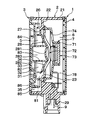
- FIG. 2 is a cross-sectional view taken along the line II-II in FIG. It is an enlarged view of the sounding body of FIG.
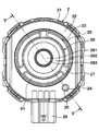
- FIG. 2 is a front view of the sound generator of FIG. 1 with a cover removed.
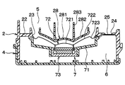
- FIG. 5 is a sectional view taken along line VV in FIG. 4.
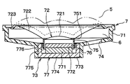
- FIG. 5 is a sectional view taken along line VV in FIG. 4. It is the enlarged view to which the VII part of FIG. 6 was expanded.
- It is an enlarged view of the sounding body of FIG. It is an enlarged view of the sounding body in the modification of 1st Embodiment.
- the sound generator of this embodiment is installed outside the passenger compartment of an automobile, for example, and is used to generate an alarm sound. As shown in FIG. 2, the sound generator includes a housing 1 in which two spaces are formed.
- the housing 1 is composed of a resin base 2, a cover 3, and a case 4.
- the base 2 includes a substantially cylindrical base tube portion 21, and a disc-shaped cover 3 that covers the opening portion is fitted into one end side opening portion of the base tube portion 21.
- a disc-shaped case 4 is hermetically bonded to the other end side opening by bonding.
- the space in the base cylinder part 21 is divided into two in the axial direction by the partition wall 22 provided in the base cylinder part 21, and the base cylinder part 21, the partition wall 22, the cover 3,
- the first space 5 is formed by the above
- the second space 6 is formed by the base cylinder portion 21, the partition wall 22, and the case 4.
- the partition wall 22 is formed with a circular through hole 23 that allows the first space 5 and the second space 6 to communicate with each other.
- the sounding body 7 that generates sound based on the electrical signal is disposed in the second space 6 so as to close the through hole 23.
- the through hole 23 is closed by a diaphragm 72 of the sounding body 7, and the second space 6 is separated from the first space 5 by the diaphragm 72.
- the partition wall 22 is formed with a vent hole 24 at a location away from the through hole 23.
- the vent hole 24 is for suppressing the occurrence of a pressure difference between the first space 5 and the second space 6 due to a temperature change.
- a ventilation film 25 is stretched on the ventilation hole 24.
- the gas permeable membrane 25 allows air to pass therethrough and blocks water, and is made of, for example, Gore-Tex (registered trademark).
- a cylindrical shielding tube portion 26 that surrounds the through hole 23 and protrudes from the partition wall 22 toward the cover 3 side is connected to the opening end of the partition wall 22.
- a beam-shaped connecting portion 27 is connected to a portion of the shielding cylinder portion 26 that is closer to the partition wall 22 than the opening end face on the cover 3 side.
- the connecting portion 27 extends from the shielding cylinder portion 26 toward the inside in the radial direction of the through hole 23, and the shielding cylinder portion 26 is connected to the shielding plate 28 via the connecting portion 27.
- the shielding plate 28 is used to prevent water flow during high-pressure car washing and snow attached to the surface of the cover 3 from reaching the sounding body 7, and to prevent damage to the sounding body 7 due to water adhesion. 1 is disposed between a sound emitting hole 84 and a diaphragm 72, which will be described later.
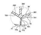
- the shielding plate 28 comes into contact with the diaphragm 72 when the diaphragm 72 is displaced during the airtight inspection, and restricts the deformation of the diaphragm 72. As shown in FIGS. 2 and 5, the shielding plate 28 is disposed in the first space 5 so as to be opposed to the diaphragm 72 and separated from the diaphragm 72, and has a shape corresponding to the diaphragm 72. Yes.
- the inner peripheral portion 281 of the shielding plate 28 has a dome shape that protrudes toward the opposite side of the diaphragm 72.
- the outer peripheral portion 282 is inclined to the side opposite to the diaphragm 72.
- the outer peripheral portion 282 has a hollow frustoconical shape that extends from the outer edge of the inner peripheral portion 281 toward the first space 5 side, and the cross section along the radial direction is directed toward the inner side in the radial direction. Curved to be convex.
- the inner peripheral part 281 and the outer peripheral part 282 are respectively facing the inner peripheral part 721 and the outer peripheral part 722 of the diaphragm 72 mentioned later.
- the shielding plate 28 contacts the diaphragm 72 at the outer edge of the inner peripheral portion 281 and the outer peripheral portion 282.
- the outer peripheral portion 282 has a shape corresponding to the outer peripheral portion 722 when the diaphragm 72 is deformed, whereby the damage to the diaphragm 72 is suppressed.
- the inner peripheral portion 281 is located closer to the case 4 than the partition wall 22 in the axial direction of the base cylinder portion 21, and the outer peripheral portion 282 is disposed so as to pass through the through hole 23.
- the end of the outer peripheral portion 282 opposite to the inner peripheral portion 281 has a cylindrical shape that protrudes toward the cover 3, and the outer peripheral portion 282 has a cylindrical shape as shown in FIG. The end portion is connected to the connecting portion 27.
- a plurality of connecting portions 27 are formed, and the sound generated by the sounding body 7 by the shielding tube portion 26, the plurality of connecting portions 27, and the shielding plate 28 is generated.
- a plurality of sound passages 81 to be passed are formed.
- the shielding plate 28 is formed with a cylindrical portion 283 that protrudes from the outer edge of the inner peripheral portion 281 toward the cover 3 side.
- a resonance chamber 82 is formed by the outer peripheral portion 282, the cylindrical portion 283, and the cover 3, and a resonance chamber 83 is formed by the inner peripheral portion 281, the cylindrical portion 283, and the cover 3.
- the sound pressure of the sound generated by the sounding body 7 is amplified by the resonance chamber 82 and the resonance chamber 83.
- a substantially square cylindrical connector 29 for electrically connecting the sounding body 7 to an external harness is formed outside the base cylindrical portion 21.
- a through hole that penetrates the base tube portion 21 and connects the inside of the connector 29 and the second space 6 is formed in the portion of the base tube portion 21 where the connector 29 is formed.
- the terminal 9 is disposed so as to pass through the through hole.
- the terminal 9 is fixed to the base cylinder portion 21 with an adhesive inside the base cylinder portion 21, and a through hole formed for arranging the terminal 9 is blocked by the adhesive and the terminal 9. ing.
- the terminal 9 is connected to a lead pin 78 described later in the second space 6.
- the cover 3 has a disk shape corresponding to the base tube portion 21.
- a protruding portion 31 that protrudes toward the inside of the housing 1 is formed in a portion of the cover 3 that faces the connecting portion 27 and the sound passage 81.
- a circular through hole 32 for releasing the sound generated by the sounding body 7 to the outside is formed in a portion of the cover 3 inside the protruding portion 31.
- a beam-shaped connecting portion 33 is connected to the opening end of the through hole 32.
- the connecting portion 33 extends radially inward of the through hole 32 and is connected to the shielding plate 34.
- the shielding plate 34 has a disc shape and is disposed so as to cover the cylindrical portion 283 of the shielding plate 28.
- a plurality of connecting portions 33 are formed, and a plurality of sound emitting holes 84 are formed by dividing the through holes 32 by the plurality of connecting portions 33.
- the sound emitting hole 84 opens the first space 5 to the atmosphere and emits the sound generated by the sound generator 7 to the outside.
- a cylindrical cylindrical portion 35 that protrudes toward the partition wall 22 is formed in a portion of the cover 3 that is located radially outward from the protruding portion 31.
- the cylindrical portion 35 is disposed in a portion of the first space 5 corresponding to the partition wall 22, and the tip of the cylindrical portion 35 is surrounded by the base cylindrical portion 21, the partition wall 22, and the shielding cylindrical portion 26. Placed in the part.
- a resonance chamber for amplifying the sound pressure of the sound generated by the sounding body 7 is formed.
- a resonance chamber 85 is formed by the base cylinder part 21, the partition wall 22, the outer peripheral part of the cover 3, and the cylinder part 35, and the outer periphery of the partition wall 22, the shielding cylinder part 26, and the cover 3.
- the resonance chamber 86 is formed by the portion, the protruding portion 31, and the cylindrical portion 35. A part of the protruding portion 31 protrudes outward in the radial direction and is connected to the cylindrical portion 35.
- the resonance chambers 82, 83, 85, 86 for amplifying the sound pressure of the sound generated by the sounding body 7 are formed.
- a large sound pressure can be obtained in a wide frequency band.
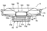
- the sounding body 7 includes a substantially stepped cylindrical frame 71, a diaphragm 72, and a drive unit 73 that vibrates the diaphragm 72.
- the frame 71 is open at both ends in the axial direction, and the wider opening of the two openings of the frame 71 is closed by the diaphragm 72.
- the frame 71 is hermetically joined to the partition wall 22 by adhesion at the end of the side where the opening is closed by the diaphragm 72.
- the frame 71 is formed with a through hole 74 that allows the inside and the outside of the frame 71 to communicate with each other, and a part of the second space 6 is configured by the space inside the frame 71. That is, the second space 6 is separated from the first space 5 by the partition wall 22 and the diaphragm 72.
- the inner peripheral portion 721 of the diaphragm 72 has a dome shape that is convex toward the first space 5 side. Further, the outer peripheral portion 722 of the diaphragm 72 is inclined toward the first space 5 side. Specifically, the outer peripheral portion 722 has a hollow frustoconical shape extending from the outer edge of the inner peripheral portion 721 toward the first space 5 side, and the cross section along the radial direction is directed toward the inner side in the radial direction. Curved to be convex.
- the inner peripheral portion 721 and the outer peripheral portion 722 are opposed to the inner peripheral portion 281 and the outer peripheral portion 282 of the shielding plate 28, respectively.
- the outer edges of the inner peripheral portion 721 and the inner peripheral portion 281 have the same shape. Specifically, the outer edge of the inner peripheral portion 721 is circular, and the outer edge of the inner peripheral portion 281 is circular with the same diameter as the outer edge of the inner peripheral portion 721.
- the inner peripheral portion 721 is displaced toward the first space 5, and the diaphragm 72 is deformed so as to swell toward the first space 5, and contacts the shielding plate 28. To do. Specifically, as shown in FIGS. 6 and 7, the outer peripheral portion 722 contacts the outer peripheral portion 282.
- the outer edges of the inner peripheral portion 721 and the inner peripheral portion 281 have the same shape.
- the diaphragm 72 and the shielding board 28 are arrange
- the inner peripheral portion 281 is more than the inner peripheral portion 721 so that a gap is formed between the inner peripheral portion 721 and the inner peripheral portion 281.
- the curvature is also high.
- the sound generator 7 sound is generated by the vibration of the diaphragm 72.
- the distance between the surface of the diaphragm 72 that contacts the shielding plate 28 and the surface of the shielding plate 28 that contacts the diaphragm 72 is such that the diaphragm 72 is not brought into contact with the shielding plate 28 by the sounding operation.
- the displacement amount is larger than 72.
- the distance between the surface of the diaphragm 72 that contacts the shielding plate 28 and the surface of the shielding plate 28 that contacts the diaphragm 72 is 1 mm or more and 6 mm or less. In the present embodiment, the distance between the outer peripheral portion 282 and the outer peripheral portion 722 is 2 mm.
- the distance between the surface of the diaphragm 72 that contacts the shielding plate 28 and the surface of the shielding plate 28 that contacts the diaphragm 72 is such that when the diaphragm 72 is displaced during the airtight inspection, It is preferable to set so that the state fitted in the space 776 is maintained. This is because the bobbin 75 needs to return to the original position in the space 776 due to the displacement of the diaphragm 72 after the airtight inspection. For example, the state in which the bobbin 75 is fitted in the space 776 is maintained by adjusting the axial dimension of the bobbin 75 and the thickness of a top plate 772 described later.
- the bobbin 75 when the bobbin 75 returns to the original position by the restoring force of the diaphragm 72, the bobbin 75 may be out of the space 776 due to the displacement of the diaphragm 72 in the airtight inspection, as shown in FIG. .
- the inner peripheral portion 281 is located closer to the case 4 than the partition wall 22 in the axial direction of the base cylinder portion 21, and the outer peripheral portion 282 is disposed so as to pass through the through hole 23.
- the inner peripheral portion 721 is positioned at the original position of the inner peripheral portion 721 in the axial direction of the frame 71 rather than the end portion of the diaphragm 72 fixed to the frame 71. Get closer. More specifically, when an end portion connected to the diaphragm 72 in the bobbin 75 described later is an end portion 751, the end portion is more in the axial direction of the bobbin 75 than the portion fixed to the frame 71 in the diaphragm 72. 751 is close to the original position of the end 751. 3 represents a portion of the diaphragm 72 that is fixed to the frame 71.
- the state in which the diaphragm 72 is inverted is a state indicated by a two-dot chain line in FIG. 3, that is, a state in which the end portion 751 of the bobbin 75 has moved beyond the portion indicated by the one-dot chain line.
- the diaphragm 72 is reversed in this way, the diaphragm 72 does not return to the original position depending on its restoring force.
- the shape of the outer peripheral portion 722 viewed from the axial direction is a ring shape, and the spring portion 723 whose cross section along the radial direction is an S shape. Is connected.
- the diaphragm 72 is bonded to the frame 71 at the end of the spring portion 723.
- the inner peripheral part 721, the outer peripheral part 722, and the spring part 723 are formed of one thin film.
- the drive unit 73 is disposed so as to block the narrower one of the two openings of the frame 71. As shown in FIG. 3, the drive unit 73 includes a bobbin 75, a voice coil 76, and a magnetic circuit unit 77.
- the bobbin 75 has a cylindrical shape, is connected to the outer edge of the inner peripheral portion 721 of the diaphragm 72, and is erected from the diaphragm 72 toward the second space 6.
- a voice coil 76 is wound around the outside of the bobbin 75.
- the bobbin 75 corresponds to a standing part and a core part.
- the magnetic circuit unit 77 is for applying a magnetic field to the voice coil 76, and includes a disc-shaped magnet 771 having one surface and the other surface, a top plate 772 connected to one surface of the magnet 771, and the magnet 771. And a yoke 773 connected to the other surface.
- the yoke 773 includes a disk-shaped bottom portion 774 connected to the magnet 771, and a cylindrical portion 775 protruding in the axial direction of the magnet 771, the top plate 772, and the bottom portion 774 from the outer peripheral portion of the bottom portion 774 toward the diaphragm 72. Yes.
- the top plate 772 and the yoke 773 are each made of a magnetic material such as iron, and correspond to a first magnetic part and a second magnetic part.
- the magnet 771 and the top plate 772 are arranged inside the cylindrical portion 775, and a cylindrical space 776 is formed between the magnet 771 and the top plate 772 and the cylindrical portion 775.
- the bobbin 75 is disposed so that the axial direction thereof coincides with the space 776 and is fitted into the space 776.
- the magnetic circuit part 77 is arranged such that the magnet 771, the top plate 772, and the cylindrical part 775 are located inside the frame 71, and the bottom part 774 closes the opening of the frame 71.
- a bobbin 75 is fitted in the space 776, and a magnetic field generated between the side surface of the top plate 772 and the side surface of the cylindrical portion 775 is applied to the voice coil 76 wound around the bobbin 75.
- the voice coil 76 When a current is passed through the voice coil 76 in a state where a magnetic field is applied, the bobbin 75 is displaced in the axial direction while being fitted in the space 776. Thereby, the diaphragm 72 vibrates and a sound is generated.
- the displacement amount of the diaphragm 72 when the diaphragm is vibrated by the driving unit is defined by a range in which the state where the bobbin 75 is fitted in the space 776 is maintained. Specifically, in the axial direction of the bobbin 75, the end of the bobbin 75 opposite to the diaphragm 72 is maintained at a position farther from the diaphragm 72 than the surface of the top plate 772 on the diaphragm 72 side. As shown, the diaphragm 72 vibrates.
- the sounding body 7 includes a lead pin 78 electrically connected to the voice coil 76, and the voice coil 76 is electrically connected to the external harness by press-fitting the lead pin 78 into the terminal 9.
- Such a sound generator is disposed outside the passenger compartment, and more specifically, is disposed in the front bumper of the vehicle such that the cover 3 is positioned on the front side of the vehicle relative to the base 2. Then, the energization of the voice coil 76 causes the diaphragm 72 to vibrate without coming into contact with the shielding plate 28, thereby generating sound.
- the sound emitted by the sounding body 7 passes through the gap formed between the shielding plate 28 and the diaphragm 72 and the sound path 81, and is amplified by the resonance chambers 82, 83, 85, 86 and released. It is emitted to the outside through the sound hole 84 or the like.
- a pressure difference is generated between the first space 5 and the second space 6.
- the first space 5 is depressurized while the vent hole 24 is closed, or the second space 6 is pressurized by air being sent from the vent hole 24 to the second space 6.
- the pressure in the second space 6 is higher than the pressure in the first space 5.
- the deformed diaphragm 72 comes into contact with the shielding plate 28, thereby restricting the deformation of the diaphragm 72. That is, the shielding plate 28 disposed inside the housing 1 suppresses the inversion and deformation of the diaphragm 72 instead of the jig that holds the diaphragm 72. Therefore, it is possible to perform an airtight inspection without using a jig for holding the diaphragm 72.
- the diaphragm 72 when the diaphragm 72 is deformed as described above, the outer edge of the inner peripheral portion 721 contacts the outer edge of the inner peripheral portion 281. Since the strength of the outer edge of the inner peripheral portion 721 is improved by the connection of the bobbin 75, the diaphragm 72 comes into contact with the shielding plate 28 at the outer edge of the inner peripheral portion 721, thereby suppressing the damage of the diaphragm 72. it can.
- the diaphragm 72 when the diaphragm 72 is deformed as described above, the diaphragm 72 contacts the shielding plate 28 at the outer peripheral portion 722 and the outer edge of the inner peripheral portion 721, and the inner peripheral portion 721 and the inner peripheral portion 281. A gap is formed between them. Therefore, damage to the diaphragm 72 in the inner peripheral portion 721 having low strength can be suppressed.
- the inner peripheral portion 281 is located closer to the case 4 than the partition wall 22 in the axial direction of the base cylinder portion 21, and the outer peripheral portion 282 includes the through hole 23. It is arranged to pass. Therefore, when the inversion of the diaphragm 72 is suppressed and the pressure difference between the first space 5 and the second space 6 decreases, the diaphragm 72 can return to its original shape or position by its own restoring force.
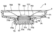
- the state where the bobbin 75 is fitted in the space 776 can be maintained during the airtight inspection. May be maintained in other ways.
- a state where the bobbin 75 is fitted in the space 776 may be maintained by laminating a plate 777 made of a nonmagnetic material such as aluminum on the top plate 772.
- a gap is formed between the outer peripheral portion 722 and the outer peripheral portion 282 when the diaphragm 72 contacts the shielding plate 28. It may be.
- the inner peripheral part 281, the outer peripheral part 282, the inner peripheral part 721, and the outer peripheral part 722 may have a shape different from that of the first embodiment.
- the inner peripheral portions 281 and 721 may be cylindrical.
- the inner peripheral portion 281 may have a shape that protrudes toward the second space 6.
- the cross section along the radial direction of the outer peripheral part 282 and the outer peripheral part 722 may be made into linear form.
Landscapes
- Engineering & Computer Science (AREA)
- Physics & Mathematics (AREA)
- Acoustics & Sound (AREA)
- Signal Processing (AREA)
- Multimedia (AREA)
- Audible-Bandwidth Dynamoelectric Transducers Other Than Pickups (AREA)
- Details Of Audible-Bandwidth Transducers (AREA)
- Diaphragms For Electromechanical Transducers (AREA)
Priority Applications (4)
| Application Number | Priority Date | Filing Date | Title |
|---|---|---|---|
| KR1020197021564A KR102160370B1 (ko) | 2017-01-26 | 2017-09-12 | 발음기 |
| DE112017006930.0T DE112017006930T5 (de) | 2017-01-26 | 2017-09-12 | Tongenerator |
| CN201780084398.3A CN110226332B (zh) | 2017-01-26 | 2017-09-12 | 发声器 |
| US16/448,008 US11051110B2 (en) | 2017-01-26 | 2019-06-21 | Sound generator |
Applications Claiming Priority (2)
| Application Number | Priority Date | Filing Date | Title |
|---|---|---|---|
| JP2017-012356 | 2017-01-26 | ||
| JP2017012356A JP6635061B2 (ja) | 2017-01-26 | 2017-01-26 | 発音器 |
Related Child Applications (1)
| Application Number | Title | Priority Date | Filing Date |
|---|---|---|---|
| US16/448,008 Continuation US11051110B2 (en) | 2017-01-26 | 2019-06-21 | Sound generator |
Publications (1)
| Publication Number | Publication Date |
|---|---|
| WO2018138955A1 true WO2018138955A1 (ja) | 2018-08-02 |
Family
ID=62978571
Family Applications (1)
| Application Number | Title | Priority Date | Filing Date |
|---|---|---|---|
| PCT/JP2017/032754 Ceased WO2018138955A1 (ja) | 2017-01-26 | 2017-09-12 | 発音器 |
Country Status (6)
| Country | Link |
|---|---|
| US (1) | US11051110B2 (enExample) |
| JP (1) | JP6635061B2 (enExample) |
| KR (1) | KR102160370B1 (enExample) |
| CN (1) | CN110226332B (enExample) |
| DE (1) | DE112017006930T5 (enExample) |
| WO (1) | WO2018138955A1 (enExample) |
Cited By (2)
| Publication number | Priority date | Publication date | Assignee | Title |
|---|---|---|---|---|
| CN113545103A (zh) * | 2019-03-13 | 2021-10-22 | 株式会社电装电子 | 发声器及其制造方法 |
| EP3761661B1 (en) * | 2019-07-01 | 2023-05-10 | Hosiden Corporation | Speaker housing and system |
Families Citing this family (11)
| Publication number | Priority date | Publication date | Assignee | Title |
|---|---|---|---|---|
| US10390143B1 (en) * | 2018-02-15 | 2019-08-20 | Bose Corporation | Electro-acoustic transducer for open audio device |
| DK180111B1 (en) * | 2018-10-04 | 2020-05-06 | Upper Level Aps | A magnet system for an electromechanical transducer |
| WO2020184022A1 (ja) | 2019-03-13 | 2020-09-17 | アンデン株式会社 | 発音器およびその製造方法 |
| WO2021134214A1 (zh) * | 2019-12-30 | 2021-07-08 | 瑞声声学科技(深圳)有限公司 | 发声器件 |
| CN212086487U (zh) * | 2020-05-25 | 2020-12-04 | 瑞声声学科技(深圳)有限公司 | 压电式mems麦克风 |
| JP7425938B2 (ja) * | 2021-03-12 | 2024-02-01 | 株式会社デンソーエレクトロニクス | 電気装置 |
| GB202103451D0 (en) | 2021-03-12 | 2021-04-28 | Pss Belgium Nv | Loudspeaker assembly for use outdoors |
| JP7494815B2 (ja) | 2021-07-20 | 2024-06-04 | 株式会社デンソーエレクトロニクス | 電気装置 |
| JP2023018351A (ja) | 2021-07-27 | 2023-02-08 | 株式会社デンソーエレクトロニクス | 電気装置、および電気装置の製造方法 |
| CN118715785A (zh) * | 2022-03-07 | 2024-09-27 | 株式会社电装电子 | 发声器 |
| WO2024122453A1 (ja) * | 2022-12-06 | 2024-06-13 | 株式会社小糸製作所 | 発音装置および車両用灯具 |
Citations (4)
| Publication number | Priority date | Publication date | Assignee | Title |
|---|---|---|---|---|
| JPS5716499A (en) * | 1980-07-04 | 1982-01-27 | Citizen Watch Co Ltd | Sound generator |
| JP2004179698A (ja) * | 2002-11-22 | 2004-06-24 | Citizen Electronics Co Ltd | 発音体の構造 |
| WO2008004272A1 (en) * | 2006-07-03 | 2008-01-10 | Pioneer Corporation | Speaker device and speaker unit |
| JP2016025558A (ja) * | 2014-07-23 | 2016-02-08 | アンデン株式会社 | 車両用発音器 |
Family Cites Families (12)
| Publication number | Priority date | Publication date | Assignee | Title |
|---|---|---|---|---|
| USRE26030E (en) * | 1956-02-28 | 1966-05-24 | Dynamic transducer | |
| US3230319A (en) * | 1963-05-24 | 1966-01-18 | Plastic Mold & Engineering Co | Dynamic ear phone |
| US4790020A (en) * | 1987-10-26 | 1988-12-06 | Lin Kuang Yao | Horn type loudspeakers |
| EP1365624B1 (en) * | 2001-02-26 | 2008-07-09 | Uetax Corporation | Speaker |
| JP4444728B2 (ja) * | 2004-05-11 | 2010-03-31 | スター精密株式会社 | 電気音響変換器 |
| US20120266590A1 (en) * | 2011-04-25 | 2012-10-25 | Resonance Technology International Inc. | Broad pressure and frequency range accumulator |
| JP2013011315A (ja) * | 2011-06-30 | 2013-01-17 | Tokai Rubber Ind Ltd | 流体封入式防振装置 |
| US10022268B2 (en) * | 2013-12-17 | 2018-07-17 | Medical Instrument Development Laboratories, Inc. | Diaphragm-position-controlled, multi-mode ocular fluid management system and method |
| JP6419031B2 (ja) | 2015-06-30 | 2018-11-07 | パラマウントベッド株式会社 | ベッド用サイドレール |
| CN205356669U (zh) * | 2015-11-30 | 2016-06-29 | 歌尔声学股份有限公司 | 一种扬声器单体 |
| JP2018050141A (ja) * | 2016-09-21 | 2018-03-29 | カシオ計算機株式会社 | 音響装置 |
| CN112154269B (zh) * | 2018-03-30 | 2023-03-10 | 德卡产品有限公司 | 液体泵送盒和相关联的压力分配歧管以及相关方法 |
-
2017
- 2017-01-26 JP JP2017012356A patent/JP6635061B2/ja active Active
- 2017-09-12 DE DE112017006930.0T patent/DE112017006930T5/de active Pending
- 2017-09-12 CN CN201780084398.3A patent/CN110226332B/zh active Active
- 2017-09-12 KR KR1020197021564A patent/KR102160370B1/ko active Active
- 2017-09-12 WO PCT/JP2017/032754 patent/WO2018138955A1/ja not_active Ceased
-
2019
- 2019-06-21 US US16/448,008 patent/US11051110B2/en active Active
Patent Citations (4)
| Publication number | Priority date | Publication date | Assignee | Title |
|---|---|---|---|---|
| JPS5716499A (en) * | 1980-07-04 | 1982-01-27 | Citizen Watch Co Ltd | Sound generator |
| JP2004179698A (ja) * | 2002-11-22 | 2004-06-24 | Citizen Electronics Co Ltd | 発音体の構造 |
| WO2008004272A1 (en) * | 2006-07-03 | 2008-01-10 | Pioneer Corporation | Speaker device and speaker unit |
| JP2016025558A (ja) * | 2014-07-23 | 2016-02-08 | アンデン株式会社 | 車両用発音器 |
Cited By (3)
| Publication number | Priority date | Publication date | Assignee | Title |
|---|---|---|---|---|
| CN113545103A (zh) * | 2019-03-13 | 2021-10-22 | 株式会社电装电子 | 发声器及其制造方法 |
| CN113545103B (zh) * | 2019-03-13 | 2024-12-24 | 株式会社电装电子 | 发声器及其制造方法 |
| EP3761661B1 (en) * | 2019-07-01 | 2023-05-10 | Hosiden Corporation | Speaker housing and system |
Also Published As
| Publication number | Publication date |
|---|---|
| CN110226332A (zh) | 2019-09-10 |
| JP2018121249A (ja) | 2018-08-02 |
| CN110226332B (zh) | 2020-11-13 |
| US11051110B2 (en) | 2021-06-29 |
| KR20190099049A (ko) | 2019-08-23 |
| JP6635061B2 (ja) | 2020-01-22 |
| KR102160370B1 (ko) | 2020-09-28 |
| DE112017006930T5 (de) | 2019-10-10 |
| US20190313192A1 (en) | 2019-10-10 |
Similar Documents
| Publication | Publication Date | Title |
|---|---|---|
| JP6635061B2 (ja) | 発音器 | |
| JP5839480B2 (ja) | スピーカ | |
| US11910139B2 (en) | Acoustic device and electronic apparatus | |
| CN113545103B (zh) | 发声器及其制造方法 | |
| JP6424963B2 (ja) | 音声出力装置 | |
| KR101559304B1 (ko) | 방수 구조를 가지는 마이크로스피커 | |
| CN103313172A (zh) | 微机械声变换器装置和相应的制造方法 | |
| WO2010050056A1 (ja) | スピーカ用連結部材及びスピーカ | |
| WO2021187080A1 (ja) | 発音器、発音器の取付構造および発音器を取り付けた車両 | |
| CN116033310A (zh) | 具有封闭壳体和膜的传声器装置 | |
| JPWO2020183865A1 (ja) | 発音器 | |
| EP3119110A1 (en) | Loudspeaker | |
| JPWO2008059595A1 (ja) | スピーカ | |
| EP1835782A2 (en) | Speaker | |
| JP4564864B2 (ja) | ダイナミックマイクロホン | |
| JP4850245B2 (ja) | 電気機械音響変換器の実装構造 | |
| JP7494815B2 (ja) | 電気装置 | |
| WO2023203654A1 (ja) | マイクロフォン | |
| WO2017037755A1 (ja) | 電気音響変換器、電気音響変換器を有する組立体およびその組立体を有する電気音響変換器装置 | |
| US20240406615A1 (en) | Sound generator | |
| JP4768822B2 (ja) | スピーカ | |
| JP2024132303A (ja) | 発音器 | |
| JP3868851B2 (ja) | 電気音響変換器 | |
| JP2008167313A (ja) | スピーカ |
Legal Events
| Date | Code | Title | Description |
|---|---|---|---|
| 121 | Ep: the epo has been informed by wipo that ep was designated in this application |
Ref document number: 17894638 Country of ref document: EP Kind code of ref document: A1 |
|
| ENP | Entry into the national phase |
Ref document number: 20197021564 Country of ref document: KR Kind code of ref document: A |
|
| 122 | Ep: pct application non-entry in european phase |
Ref document number: 17894638 Country of ref document: EP Kind code of ref document: A1 |