WO2018138955A1 - Sound generator - Google Patents
Sound generator Download PDFInfo
- Publication number
- WO2018138955A1 WO2018138955A1 PCT/JP2017/032754 JP2017032754W WO2018138955A1 WO 2018138955 A1 WO2018138955 A1 WO 2018138955A1 JP 2017032754 W JP2017032754 W JP 2017032754W WO 2018138955 A1 WO2018138955 A1 WO 2018138955A1
- Authority
- WO
- WIPO (PCT)
- Prior art keywords
- diaphragm
- space
- inner peripheral
- shielding plate
- sound generator
- Prior art date
Links
Images


Classifications
-
- H—ELECTRICITY
- H04—ELECTRIC COMMUNICATION TECHNIQUE
- H04R—LOUDSPEAKERS, MICROPHONES, GRAMOPHONE PICK-UPS OR LIKE ACOUSTIC ELECTROMECHANICAL TRANSDUCERS; DEAF-AID SETS; PUBLIC ADDRESS SYSTEMS
- H04R1/00—Details of transducers, loudspeakers or microphones
- H04R1/02—Casings; Cabinets ; Supports therefor; Mountings therein
- H04R1/023—Screens for loudspeakers
-
- H—ELECTRICITY
- H04—ELECTRIC COMMUNICATION TECHNIQUE
- H04R—LOUDSPEAKERS, MICROPHONES, GRAMOPHONE PICK-UPS OR LIKE ACOUSTIC ELECTROMECHANICAL TRANSDUCERS; DEAF-AID SETS; PUBLIC ADDRESS SYSTEMS
- H04R7/00—Diaphragms for electromechanical transducers; Cones
- H04R7/02—Diaphragms for electromechanical transducers; Cones characterised by the construction
- H04R7/12—Non-planar diaphragms or cones
-
- H—ELECTRICITY
- H04—ELECTRIC COMMUNICATION TECHNIQUE
- H04R—LOUDSPEAKERS, MICROPHONES, GRAMOPHONE PICK-UPS OR LIKE ACOUSTIC ELECTROMECHANICAL TRANSDUCERS; DEAF-AID SETS; PUBLIC ADDRESS SYSTEMS
- H04R1/00—Details of transducers, loudspeakers or microphones
-
- H—ELECTRICITY
- H04—ELECTRIC COMMUNICATION TECHNIQUE
- H04R—LOUDSPEAKERS, MICROPHONES, GRAMOPHONE PICK-UPS OR LIKE ACOUSTIC ELECTROMECHANICAL TRANSDUCERS; DEAF-AID SETS; PUBLIC ADDRESS SYSTEMS
- H04R1/00—Details of transducers, loudspeakers or microphones
- H04R1/02—Casings; Cabinets ; Supports therefor; Mountings therein
-
- H—ELECTRICITY
- H04—ELECTRIC COMMUNICATION TECHNIQUE
- H04R—LOUDSPEAKERS, MICROPHONES, GRAMOPHONE PICK-UPS OR LIKE ACOUSTIC ELECTROMECHANICAL TRANSDUCERS; DEAF-AID SETS; PUBLIC ADDRESS SYSTEMS
- H04R9/00—Transducers of moving-coil, moving-strip, or moving-wire type
- H04R9/02—Details
- H04R9/025—Magnetic circuit
-
- H—ELECTRICITY
- H04—ELECTRIC COMMUNICATION TECHNIQUE
- H04R—LOUDSPEAKERS, MICROPHONES, GRAMOPHONE PICK-UPS OR LIKE ACOUSTIC ELECTROMECHANICAL TRANSDUCERS; DEAF-AID SETS; PUBLIC ADDRESS SYSTEMS
- H04R9/00—Transducers of moving-coil, moving-strip, or moving-wire type
- H04R9/02—Details
- H04R9/04—Construction, mounting, or centering of coil
- H04R9/046—Construction
-
- H—ELECTRICITY
- H04—ELECTRIC COMMUNICATION TECHNIQUE
- H04R—LOUDSPEAKERS, MICROPHONES, GRAMOPHONE PICK-UPS OR LIKE ACOUSTIC ELECTROMECHANICAL TRANSDUCERS; DEAF-AID SETS; PUBLIC ADDRESS SYSTEMS
- H04R9/00—Transducers of moving-coil, moving-strip, or moving-wire type
- H04R9/06—Loudspeakers
-
- B—PERFORMING OPERATIONS; TRANSPORTING
- B60—VEHICLES IN GENERAL
- B60Q—ARRANGEMENT OF SIGNALLING OR LIGHTING DEVICES, THE MOUNTING OR SUPPORTING THEREOF OR CIRCUITS THEREFOR, FOR VEHICLES IN GENERAL
- B60Q5/00—Arrangement or adaptation of acoustic signal devices
-
- H—ELECTRICITY
- H04—ELECTRIC COMMUNICATION TECHNIQUE
- H04R—LOUDSPEAKERS, MICROPHONES, GRAMOPHONE PICK-UPS OR LIKE ACOUSTIC ELECTROMECHANICAL TRANSDUCERS; DEAF-AID SETS; PUBLIC ADDRESS SYSTEMS
- H04R2400/00—Loudspeakers
- H04R2400/11—Aspects regarding the frame of loudspeaker transducers
-
- H—ELECTRICITY
- H04—ELECTRIC COMMUNICATION TECHNIQUE
- H04R—LOUDSPEAKERS, MICROPHONES, GRAMOPHONE PICK-UPS OR LIKE ACOUSTIC ELECTROMECHANICAL TRANSDUCERS; DEAF-AID SETS; PUBLIC ADDRESS SYSTEMS
- H04R2499/00—Aspects covered by H04R or H04S not otherwise provided for in their subgroups
- H04R2499/10—General applications
- H04R2499/13—Acoustic transducers and sound field adaptation in vehicles
-
- H—ELECTRICITY
- H04—ELECTRIC COMMUNICATION TECHNIQUE
- H04R—LOUDSPEAKERS, MICROPHONES, GRAMOPHONE PICK-UPS OR LIKE ACOUSTIC ELECTROMECHANICAL TRANSDUCERS; DEAF-AID SETS; PUBLIC ADDRESS SYSTEMS
- H04R7/00—Diaphragms for electromechanical transducers; Cones
- H04R7/16—Mounting or tensioning of diaphragms or cones
- H04R7/18—Mounting or tensioning of diaphragms or cones at the periphery
Definitions
- This disclosure relates to sound generators.
- Patent Document 1 Conventionally, as a vehicle sound generator used for a vehicle alarm device, a vehicle approach notification device, or the like, there is one described in Patent Document 1, for example.
- a shielding plate is installed in front of the diaphragm inside the base casing for the purpose of achieving both acoustic performance and water and snow intrusion prevention function.
- the sound generator is a sealed product, and airtight inspection is performed to guarantee the waterproof performance and sealing performance of the sound generator.
- airtight inspection it is necessary to hold down the diaphragm with a jig or the like in order to suppress the inversion of the diaphragm due to air pressure and stabilize the inspection result.
- This disclosure is intended to provide a sound generator capable of performing an airtight inspection without using a jig for holding a diaphragm.
- a sound generator that generates sound by vibrating a diaphragm includes a first space opened to the atmosphere by a sound emitting hole and a second space separated from the first space by the diaphragm.
- a housing formed and a shielding plate disposed in the first space in a state of being separated from the diaphragm so as to face the diaphragm.
- the deformation of the diaphragm is restricted by the contact between the diaphragm and the shielding plate, and the shielding plate serves as a substitute for the jig for pressing the diaphragm. Therefore, it is possible to perform an airtight inspection without using a jig for holding the diaphragm.
- the sound generator may further include a drive unit that vibrates the diaphragm.
- the distance between the diaphragm and the contact surface of the shielding plate that contacts the diaphragm is set larger than the displacement of the diaphragm when the diaphragm vibrates by the drive unit.
- the drive unit includes a cylindrical core portion standing up toward the second space of the diaphragm, a voice coil wound around the core portion, and a cylindrical space whose axial direction coincides with the core portion. And a magnetic circuit part that displaces the core part while being fitted in the space by applying a magnetic field to the voice coil.
- the displacement amount of the diaphragm is defined by a range in which the state where the core portion is fitted in the space is maintained.
- the amount of displacement of the diaphragm is defined by, for example, a range in which the state where the core portion is fitted in the space is maintained, and by making the distance between the diaphragm and the shielding plate larger than this displacement amount, And the shielding plate can be suppressed.
- the distance between the diaphragm and the contact surface of the shielding plate that contacts the diaphragm may be 1 mm or more and 6 mm or less.
- the distance between the shielding plate and the diaphragm is 1 mm or more and 6 mm or less, the contact between the diaphragm and the shielding plate due to the sound generation operation can be suppressed.
- the deformation of the diaphragm is limited by the outer edge of the inner peripheral portion of the diaphragm coming into contact with the outer edge of the inner peripheral portion of the shielding plate, and when the deformation of the diaphragm is restricted by the shielding plate, the diaphragm is shielded from the inner peripheral portion of the diaphragm. A gap is formed between the inner periphery of the plate.
- the inner peripheral part of the diaphragm is low in strength, but the inner peripheral part of the diaphragm and the inner peripheral part of the shielding plate are in contact with each other at the outer edge, and a gap is formed between them, so that the diaphragm can be deformed or damaged. Can be suppressed.
- the diaphragm may include a standing portion that is erected from the outer edge of the inner peripheral portion toward the second space. When the deformation of the diaphragm is restricted by the shielding plate, the diaphragm comes into contact with the shielding plate at the portion where the standing portion is formed.
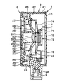
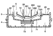
- FIG. 2 is a cross-sectional view taken along the line II-II in FIG. It is an enlarged view of the sounding body of FIG.
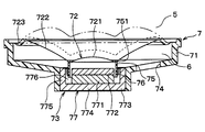
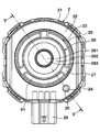
- FIG. 2 is a front view of the sound generator of FIG. 1 with a cover removed.
- FIG. 5 is a sectional view taken along line VV in FIG. 4.
- FIG. 5 is a sectional view taken along line VV in FIG. 4. It is the enlarged view to which the VII part of FIG. 6 was expanded.
- It is an enlarged view of the sounding body of FIG. It is an enlarged view of the sounding body in the modification of 1st Embodiment.
- the sound generator of this embodiment is installed outside the passenger compartment of an automobile, for example, and is used to generate an alarm sound. As shown in FIG. 2, the sound generator includes a housing 1 in which two spaces are formed.
- the housing 1 is composed of a resin base 2, a cover 3, and a case 4.
- the base 2 includes a substantially cylindrical base tube portion 21, and a disc-shaped cover 3 that covers the opening portion is fitted into one end side opening portion of the base tube portion 21.
- a disc-shaped case 4 is hermetically bonded to the other end side opening by bonding.
- the space in the base cylinder part 21 is divided into two in the axial direction by the partition wall 22 provided in the base cylinder part 21, and the base cylinder part 21, the partition wall 22, the cover 3,
- the first space 5 is formed by the above
- the second space 6 is formed by the base cylinder portion 21, the partition wall 22, and the case 4.
- the partition wall 22 is formed with a circular through hole 23 that allows the first space 5 and the second space 6 to communicate with each other.
- the sounding body 7 that generates sound based on the electrical signal is disposed in the second space 6 so as to close the through hole 23.
- the through hole 23 is closed by a diaphragm 72 of the sounding body 7, and the second space 6 is separated from the first space 5 by the diaphragm 72.
- the partition wall 22 is formed with a vent hole 24 at a location away from the through hole 23.
- the vent hole 24 is for suppressing the occurrence of a pressure difference between the first space 5 and the second space 6 due to a temperature change.
- a ventilation film 25 is stretched on the ventilation hole 24.
- the gas permeable membrane 25 allows air to pass therethrough and blocks water, and is made of, for example, Gore-Tex (registered trademark).
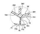
- a cylindrical shielding tube portion 26 that surrounds the through hole 23 and protrudes from the partition wall 22 toward the cover 3 side is connected to the opening end of the partition wall 22.
- a beam-shaped connecting portion 27 is connected to a portion of the shielding cylinder portion 26 that is closer to the partition wall 22 than the opening end face on the cover 3 side.
- the connecting portion 27 extends from the shielding cylinder portion 26 toward the inside in the radial direction of the through hole 23, and the shielding cylinder portion 26 is connected to the shielding plate 28 via the connecting portion 27.
- the shielding plate 28 is used to prevent water flow during high-pressure car washing and snow attached to the surface of the cover 3 from reaching the sounding body 7, and to prevent damage to the sounding body 7 due to water adhesion. 1 is disposed between a sound emitting hole 84 and a diaphragm 72, which will be described later.
- the shielding plate 28 comes into contact with the diaphragm 72 when the diaphragm 72 is displaced during the airtight inspection, and restricts the deformation of the diaphragm 72. As shown in FIGS. 2 and 5, the shielding plate 28 is disposed in the first space 5 so as to be opposed to the diaphragm 72 and separated from the diaphragm 72, and has a shape corresponding to the diaphragm 72. Yes.
- the inner peripheral portion 281 of the shielding plate 28 has a dome shape that protrudes toward the opposite side of the diaphragm 72.
- the outer peripheral portion 282 is inclined to the side opposite to the diaphragm 72.
- the outer peripheral portion 282 has a hollow frustoconical shape that extends from the outer edge of the inner peripheral portion 281 toward the first space 5 side, and the cross section along the radial direction is directed toward the inner side in the radial direction. Curved to be convex.
- the inner peripheral part 281 and the outer peripheral part 282 are respectively facing the inner peripheral part 721 and the outer peripheral part 722 of the diaphragm 72 mentioned later.
- the shielding plate 28 contacts the diaphragm 72 at the outer edge of the inner peripheral portion 281 and the outer peripheral portion 282.
- the outer peripheral portion 282 has a shape corresponding to the outer peripheral portion 722 when the diaphragm 72 is deformed, whereby the damage to the diaphragm 72 is suppressed.
- the inner peripheral portion 281 is located closer to the case 4 than the partition wall 22 in the axial direction of the base cylinder portion 21, and the outer peripheral portion 282 is disposed so as to pass through the through hole 23.
- the end of the outer peripheral portion 282 opposite to the inner peripheral portion 281 has a cylindrical shape that protrudes toward the cover 3, and the outer peripheral portion 282 has a cylindrical shape as shown in FIG. The end portion is connected to the connecting portion 27.
- a plurality of connecting portions 27 are formed, and the sound generated by the sounding body 7 by the shielding tube portion 26, the plurality of connecting portions 27, and the shielding plate 28 is generated.
- a plurality of sound passages 81 to be passed are formed.
- the shielding plate 28 is formed with a cylindrical portion 283 that protrudes from the outer edge of the inner peripheral portion 281 toward the cover 3 side.
- a resonance chamber 82 is formed by the outer peripheral portion 282, the cylindrical portion 283, and the cover 3, and a resonance chamber 83 is formed by the inner peripheral portion 281, the cylindrical portion 283, and the cover 3.
- the sound pressure of the sound generated by the sounding body 7 is amplified by the resonance chamber 82 and the resonance chamber 83.
- a substantially square cylindrical connector 29 for electrically connecting the sounding body 7 to an external harness is formed outside the base cylindrical portion 21.
- a through hole that penetrates the base tube portion 21 and connects the inside of the connector 29 and the second space 6 is formed in the portion of the base tube portion 21 where the connector 29 is formed.
- the terminal 9 is disposed so as to pass through the through hole.
- the terminal 9 is fixed to the base cylinder portion 21 with an adhesive inside the base cylinder portion 21, and a through hole formed for arranging the terminal 9 is blocked by the adhesive and the terminal 9. ing.
- the terminal 9 is connected to a lead pin 78 described later in the second space 6.
- the cover 3 has a disk shape corresponding to the base tube portion 21.
- a protruding portion 31 that protrudes toward the inside of the housing 1 is formed in a portion of the cover 3 that faces the connecting portion 27 and the sound passage 81.
- a circular through hole 32 for releasing the sound generated by the sounding body 7 to the outside is formed in a portion of the cover 3 inside the protruding portion 31.
- a beam-shaped connecting portion 33 is connected to the opening end of the through hole 32.
- the connecting portion 33 extends radially inward of the through hole 32 and is connected to the shielding plate 34.
- the shielding plate 34 has a disc shape and is disposed so as to cover the cylindrical portion 283 of the shielding plate 28.
- a plurality of connecting portions 33 are formed, and a plurality of sound emitting holes 84 are formed by dividing the through holes 32 by the plurality of connecting portions 33.
- the sound emitting hole 84 opens the first space 5 to the atmosphere and emits the sound generated by the sound generator 7 to the outside.
- a cylindrical cylindrical portion 35 that protrudes toward the partition wall 22 is formed in a portion of the cover 3 that is located radially outward from the protruding portion 31.
- the cylindrical portion 35 is disposed in a portion of the first space 5 corresponding to the partition wall 22, and the tip of the cylindrical portion 35 is surrounded by the base cylindrical portion 21, the partition wall 22, and the shielding cylindrical portion 26. Placed in the part.
- a resonance chamber for amplifying the sound pressure of the sound generated by the sounding body 7 is formed.
- a resonance chamber 85 is formed by the base cylinder part 21, the partition wall 22, the outer peripheral part of the cover 3, and the cylinder part 35, and the outer periphery of the partition wall 22, the shielding cylinder part 26, and the cover 3.
- the resonance chamber 86 is formed by the portion, the protruding portion 31, and the cylindrical portion 35. A part of the protruding portion 31 protrudes outward in the radial direction and is connected to the cylindrical portion 35.
- the resonance chambers 82, 83, 85, 86 for amplifying the sound pressure of the sound generated by the sounding body 7 are formed.
- a large sound pressure can be obtained in a wide frequency band.
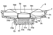
- the sounding body 7 includes a substantially stepped cylindrical frame 71, a diaphragm 72, and a drive unit 73 that vibrates the diaphragm 72.
- the frame 71 is open at both ends in the axial direction, and the wider opening of the two openings of the frame 71 is closed by the diaphragm 72.
- the frame 71 is hermetically joined to the partition wall 22 by adhesion at the end of the side where the opening is closed by the diaphragm 72.
- the frame 71 is formed with a through hole 74 that allows the inside and the outside of the frame 71 to communicate with each other, and a part of the second space 6 is configured by the space inside the frame 71. That is, the second space 6 is separated from the first space 5 by the partition wall 22 and the diaphragm 72.
- the inner peripheral portion 721 of the diaphragm 72 has a dome shape that is convex toward the first space 5 side. Further, the outer peripheral portion 722 of the diaphragm 72 is inclined toward the first space 5 side. Specifically, the outer peripheral portion 722 has a hollow frustoconical shape extending from the outer edge of the inner peripheral portion 721 toward the first space 5 side, and the cross section along the radial direction is directed toward the inner side in the radial direction. Curved to be convex.
- the inner peripheral portion 721 and the outer peripheral portion 722 are opposed to the inner peripheral portion 281 and the outer peripheral portion 282 of the shielding plate 28, respectively.
- the outer edges of the inner peripheral portion 721 and the inner peripheral portion 281 have the same shape. Specifically, the outer edge of the inner peripheral portion 721 is circular, and the outer edge of the inner peripheral portion 281 is circular with the same diameter as the outer edge of the inner peripheral portion 721.
- the inner peripheral portion 721 is displaced toward the first space 5, and the diaphragm 72 is deformed so as to swell toward the first space 5, and contacts the shielding plate 28. To do. Specifically, as shown in FIGS. 6 and 7, the outer peripheral portion 722 contacts the outer peripheral portion 282.
- the outer edges of the inner peripheral portion 721 and the inner peripheral portion 281 have the same shape.
- the diaphragm 72 and the shielding board 28 are arrange
- the inner peripheral portion 281 is more than the inner peripheral portion 721 so that a gap is formed between the inner peripheral portion 721 and the inner peripheral portion 281.
- the curvature is also high.
- the sound generator 7 sound is generated by the vibration of the diaphragm 72.
- the distance between the surface of the diaphragm 72 that contacts the shielding plate 28 and the surface of the shielding plate 28 that contacts the diaphragm 72 is such that the diaphragm 72 is not brought into contact with the shielding plate 28 by the sounding operation.
- the displacement amount is larger than 72.
- the distance between the surface of the diaphragm 72 that contacts the shielding plate 28 and the surface of the shielding plate 28 that contacts the diaphragm 72 is 1 mm or more and 6 mm or less. In the present embodiment, the distance between the outer peripheral portion 282 and the outer peripheral portion 722 is 2 mm.
- the distance between the surface of the diaphragm 72 that contacts the shielding plate 28 and the surface of the shielding plate 28 that contacts the diaphragm 72 is such that when the diaphragm 72 is displaced during the airtight inspection, It is preferable to set so that the state fitted in the space 776 is maintained. This is because the bobbin 75 needs to return to the original position in the space 776 due to the displacement of the diaphragm 72 after the airtight inspection. For example, the state in which the bobbin 75 is fitted in the space 776 is maintained by adjusting the axial dimension of the bobbin 75 and the thickness of a top plate 772 described later.
- the bobbin 75 when the bobbin 75 returns to the original position by the restoring force of the diaphragm 72, the bobbin 75 may be out of the space 776 due to the displacement of the diaphragm 72 in the airtight inspection, as shown in FIG. .
- the inner peripheral portion 281 is located closer to the case 4 than the partition wall 22 in the axial direction of the base cylinder portion 21, and the outer peripheral portion 282 is disposed so as to pass through the through hole 23.
- the inner peripheral portion 721 is positioned at the original position of the inner peripheral portion 721 in the axial direction of the frame 71 rather than the end portion of the diaphragm 72 fixed to the frame 71. Get closer. More specifically, when an end portion connected to the diaphragm 72 in the bobbin 75 described later is an end portion 751, the end portion is more in the axial direction of the bobbin 75 than the portion fixed to the frame 71 in the diaphragm 72. 751 is close to the original position of the end 751. 3 represents a portion of the diaphragm 72 that is fixed to the frame 71.
- the state in which the diaphragm 72 is inverted is a state indicated by a two-dot chain line in FIG. 3, that is, a state in which the end portion 751 of the bobbin 75 has moved beyond the portion indicated by the one-dot chain line.
- the diaphragm 72 is reversed in this way, the diaphragm 72 does not return to the original position depending on its restoring force.
- the shape of the outer peripheral portion 722 viewed from the axial direction is a ring shape, and the spring portion 723 whose cross section along the radial direction is an S shape. Is connected.
- the diaphragm 72 is bonded to the frame 71 at the end of the spring portion 723.
- the inner peripheral part 721, the outer peripheral part 722, and the spring part 723 are formed of one thin film.
- the drive unit 73 is disposed so as to block the narrower one of the two openings of the frame 71. As shown in FIG. 3, the drive unit 73 includes a bobbin 75, a voice coil 76, and a magnetic circuit unit 77.
- the bobbin 75 has a cylindrical shape, is connected to the outer edge of the inner peripheral portion 721 of the diaphragm 72, and is erected from the diaphragm 72 toward the second space 6.
- a voice coil 76 is wound around the outside of the bobbin 75.
- the bobbin 75 corresponds to a standing part and a core part.
- the magnetic circuit unit 77 is for applying a magnetic field to the voice coil 76, and includes a disc-shaped magnet 771 having one surface and the other surface, a top plate 772 connected to one surface of the magnet 771, and the magnet 771. And a yoke 773 connected to the other surface.
- the yoke 773 includes a disk-shaped bottom portion 774 connected to the magnet 771, and a cylindrical portion 775 protruding in the axial direction of the magnet 771, the top plate 772, and the bottom portion 774 from the outer peripheral portion of the bottom portion 774 toward the diaphragm 72. Yes.
- the top plate 772 and the yoke 773 are each made of a magnetic material such as iron, and correspond to a first magnetic part and a second magnetic part.
- the magnet 771 and the top plate 772 are arranged inside the cylindrical portion 775, and a cylindrical space 776 is formed between the magnet 771 and the top plate 772 and the cylindrical portion 775.
- the bobbin 75 is disposed so that the axial direction thereof coincides with the space 776 and is fitted into the space 776.
- the magnetic circuit part 77 is arranged such that the magnet 771, the top plate 772, and the cylindrical part 775 are located inside the frame 71, and the bottom part 774 closes the opening of the frame 71.
- a bobbin 75 is fitted in the space 776, and a magnetic field generated between the side surface of the top plate 772 and the side surface of the cylindrical portion 775 is applied to the voice coil 76 wound around the bobbin 75.
- the voice coil 76 When a current is passed through the voice coil 76 in a state where a magnetic field is applied, the bobbin 75 is displaced in the axial direction while being fitted in the space 776. Thereby, the diaphragm 72 vibrates and a sound is generated.
- the displacement amount of the diaphragm 72 when the diaphragm is vibrated by the driving unit is defined by a range in which the state where the bobbin 75 is fitted in the space 776 is maintained. Specifically, in the axial direction of the bobbin 75, the end of the bobbin 75 opposite to the diaphragm 72 is maintained at a position farther from the diaphragm 72 than the surface of the top plate 772 on the diaphragm 72 side. As shown, the diaphragm 72 vibrates.
- the sounding body 7 includes a lead pin 78 electrically connected to the voice coil 76, and the voice coil 76 is electrically connected to the external harness by press-fitting the lead pin 78 into the terminal 9.
- Such a sound generator is disposed outside the passenger compartment, and more specifically, is disposed in the front bumper of the vehicle such that the cover 3 is positioned on the front side of the vehicle relative to the base 2. Then, the energization of the voice coil 76 causes the diaphragm 72 to vibrate without coming into contact with the shielding plate 28, thereby generating sound.
- the sound emitted by the sounding body 7 passes through the gap formed between the shielding plate 28 and the diaphragm 72 and the sound path 81, and is amplified by the resonance chambers 82, 83, 85, 86 and released. It is emitted to the outside through the sound hole 84 or the like.
- a pressure difference is generated between the first space 5 and the second space 6.
- the first space 5 is depressurized while the vent hole 24 is closed, or the second space 6 is pressurized by air being sent from the vent hole 24 to the second space 6.
- the pressure in the second space 6 is higher than the pressure in the first space 5.
- the deformed diaphragm 72 comes into contact with the shielding plate 28, thereby restricting the deformation of the diaphragm 72. That is, the shielding plate 28 disposed inside the housing 1 suppresses the inversion and deformation of the diaphragm 72 instead of the jig that holds the diaphragm 72. Therefore, it is possible to perform an airtight inspection without using a jig for holding the diaphragm 72.
- the diaphragm 72 when the diaphragm 72 is deformed as described above, the outer edge of the inner peripheral portion 721 contacts the outer edge of the inner peripheral portion 281. Since the strength of the outer edge of the inner peripheral portion 721 is improved by the connection of the bobbin 75, the diaphragm 72 comes into contact with the shielding plate 28 at the outer edge of the inner peripheral portion 721, thereby suppressing the damage of the diaphragm 72. it can.
- the diaphragm 72 when the diaphragm 72 is deformed as described above, the diaphragm 72 contacts the shielding plate 28 at the outer peripheral portion 722 and the outer edge of the inner peripheral portion 721, and the inner peripheral portion 721 and the inner peripheral portion 281. A gap is formed between them. Therefore, damage to the diaphragm 72 in the inner peripheral portion 721 having low strength can be suppressed.
- the inner peripheral portion 281 is located closer to the case 4 than the partition wall 22 in the axial direction of the base cylinder portion 21, and the outer peripheral portion 282 includes the through hole 23. It is arranged to pass. Therefore, when the inversion of the diaphragm 72 is suppressed and the pressure difference between the first space 5 and the second space 6 decreases, the diaphragm 72 can return to its original shape or position by its own restoring force.
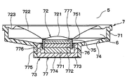
- the state where the bobbin 75 is fitted in the space 776 can be maintained during the airtight inspection. May be maintained in other ways.
- a state where the bobbin 75 is fitted in the space 776 may be maintained by laminating a plate 777 made of a nonmagnetic material such as aluminum on the top plate 772.
- a gap is formed between the outer peripheral portion 722 and the outer peripheral portion 282 when the diaphragm 72 contacts the shielding plate 28. It may be.
- the inner peripheral part 281, the outer peripheral part 282, the inner peripheral part 721, and the outer peripheral part 722 may have a shape different from that of the first embodiment.
- the inner peripheral portions 281 and 721 may be cylindrical.
- the inner peripheral portion 281 may have a shape that protrudes toward the second space 6.
- the cross section along the radial direction of the outer peripheral part 282 and the outer peripheral part 722 may be made into linear form.
Abstract
This sound generator for generating sound by vibrating a diaphragm (72) is provided with: a housing (1) having formed therein a first space (5) which is open to the atmosphere through a sound release hole (84), and also having formed therein a second space (6) separated from the first space by the diaphragm; and a closure plate (28) disposed in the first space so as to face the diaphragm while being separated from the diaphragm. When the diaphragm is displaced toward the first space by the difference in pressure between the first space and the second space, the diaphragm comes into contact with the closure plate and is restricted to deform.
Description
本出願は、2017年1月26日に出願された日本特許出願2017-12356号に基づくもので、ここにその記載内容を援用する。
This application is based on Japanese Patent Application No. 2017-12356 filed on Jan. 26, 2017, the contents of which are incorporated herein by reference.
本開示は、発音器に関する。
This disclosure relates to sound generators.
従来、車両用警報器や車両用接近通報装置等に用いられる車両用発音器として、例えば特許文献1に記載されたものがある。この特許文献1に記載された車両用発音器では、音響性能と水や雪の侵入防止機能を両立させる目的で、ベース筐体の内部においてダイヤフラムの手前に遮蔽板が設置されている。
Conventionally, as a vehicle sound generator used for a vehicle alarm device, a vehicle approach notification device, or the like, there is one described in Patent Document 1, for example. In the vehicle sound generator described in Patent Document 1, a shielding plate is installed in front of the diaphragm inside the base casing for the purpose of achieving both acoustic performance and water and snow intrusion prevention function.
発音器は密閉製品であり、発音器の防水性能および密閉性能の保証のために気密検査が行われる。この気密検査では、空気圧によるダイヤフラムの反転などを抑制し、検査結果を安定させるために、治具などでダイヤフラムを押さえる必要がある。
The sound generator is a sealed product, and airtight inspection is performed to guarantee the waterproof performance and sealing performance of the sound generator. In this airtight inspection, it is necessary to hold down the diaphragm with a jig or the like in order to suppress the inversion of the diaphragm due to air pressure and stabilize the inspection result.
しかしながら、ベース筐体の内部においてダイヤフラムの手前に遮蔽板が設置された構成では、治具を用いてダイヤフラムを押さえるためには、遮蔽板を取り外す必要があり、部品数の増加や金型費の上昇につながる。
However, in a configuration in which a shielding plate is installed in front of the diaphragm inside the base housing, it is necessary to remove the shielding plate in order to hold the diaphragm using a jig, which increases the number of parts and the cost of the mold. Leading to a rise.
本開示は、ダイヤフラムを押さえる治具を使用せずに気密検査を行うことが可能な発音器を提供することを目的とする。
This disclosure is intended to provide a sound generator capable of performing an airtight inspection without using a jig for holding a diaphragm.
本開示の一態様において、ダイヤフラムを振動させて音を発生させる発音器は、放音孔によって大気に開放された第1空間、および、ダイヤフラムによって第1空間と隔てられた第2空間が内部に形成された筐体と、ダイヤフラムに対向するようにダイヤフラムから離された状態で第1空間に配置された遮蔽板と、を備える。第1空間と第2空間との圧力差によってダイヤフラムが第1空間に向かって変位したとき、ダイヤフラムが遮蔽板に接触することによって、ダイヤフラムの変形が制限される。
In one embodiment of the present disclosure, a sound generator that generates sound by vibrating a diaphragm includes a first space opened to the atmosphere by a sound emitting hole and a second space separated from the first space by the diaphragm. A housing formed and a shielding plate disposed in the first space in a state of being separated from the diaphragm so as to face the diaphragm. When the diaphragm is displaced toward the first space due to the pressure difference between the first space and the second space, deformation of the diaphragm is limited by the diaphragm coming into contact with the shielding plate.
これによれば、ダイヤフラムと遮蔽板との接触によってダイヤフラムの変形が制限され、遮蔽板がダイヤフラムを押さえる治具の代わりとなる。したがって、ダイヤフラムを押さえる治具を使用せずに気密検査を行うことが可能となる。
According to this, the deformation of the diaphragm is restricted by the contact between the diaphragm and the shielding plate, and the shielding plate serves as a substitute for the jig for pressing the diaphragm. Therefore, it is possible to perform an airtight inspection without using a jig for holding the diaphragm.
また、発音器は、ダイヤフラムを振動させる駆動部をさらに備えてもよい。ダイヤフラムと、遮蔽板のうちダイヤフラムに接触する接触面との間の距離は、駆動部によってダイヤフラムが振動するときのダイヤフラムの変位量よりも大きくされている。
Further, the sound generator may further include a drive unit that vibrates the diaphragm. The distance between the diaphragm and the contact surface of the shielding plate that contacts the diaphragm is set larger than the displacement of the diaphragm when the diaphragm vibrates by the drive unit.
このような構成によれば、発音動作によるダイヤフラムと遮蔽板との接触を抑制することができる。
According to such a configuration, the contact between the diaphragm and the shielding plate due to the sound generation operation can be suppressed.
また、駆動部は、ダイヤフラムのうち第2空間に向かって立設された筒状の芯部と、芯部に巻かれたボイスコイルと、芯部と軸方向が一致する筒状の空間が内部に形成されており、ボイスコイルに磁界を印加することで、芯部を空間にはめ込まれた状態で変位させる磁気回路部と、を備えてもよい。ダイヤフラムの変位量は、芯部が空間にはめ込まれた状態が維持される範囲によって規定される。
Further, the drive unit includes a cylindrical core portion standing up toward the second space of the diaphragm, a voice coil wound around the core portion, and a cylindrical space whose axial direction coincides with the core portion. And a magnetic circuit part that displaces the core part while being fitted in the space by applying a magnetic field to the voice coil. The displacement amount of the diaphragm is defined by a range in which the state where the core portion is fitted in the space is maintained.
ダイヤフラムの変位量は、例えばこのように芯部が空間にはめ込まれた状態が維持される範囲によって規定され、この変位量よりもダイヤフラムと遮蔽板との距離を大きくすることによって、発音動作によるダイヤフラムと遮蔽板との接触を抑制することができる。
The amount of displacement of the diaphragm is defined by, for example, a range in which the state where the core portion is fitted in the space is maintained, and by making the distance between the diaphragm and the shielding plate larger than this displacement amount, And the shielding plate can be suppressed.
また、ダイヤフラムと、遮蔽板のうちダイヤフラムに接触する接触面との間の距離は、1mm以上6mm以下としてもよい。
Further, the distance between the diaphragm and the contact surface of the shielding plate that contacts the diaphragm may be 1 mm or more and 6 mm or less.
このように遮蔽板とダイヤフラムとの距離を1mm以上6mm以下とすることによっても、発音動作によるダイヤフラムと遮蔽板との接触を抑制することができる。
Thus, even when the distance between the shielding plate and the diaphragm is 1 mm or more and 6 mm or less, the contact between the diaphragm and the shielding plate due to the sound generation operation can be suppressed.
また、ダイヤフラムの変形は、ダイヤフラムの内周部の外縁が遮蔽板の内周部の外縁に接触することによって制限され、ダイヤフラムの変形が遮蔽板によって制限されたとき、ダイヤフラムの内周部と遮蔽板の内周部との間に隙間が形成される。
Further, the deformation of the diaphragm is limited by the outer edge of the inner peripheral portion of the diaphragm coming into contact with the outer edge of the inner peripheral portion of the shielding plate, and when the deformation of the diaphragm is restricted by the shielding plate, the diaphragm is shielded from the inner peripheral portion of the diaphragm. A gap is formed between the inner periphery of the plate.
ダイヤフラムの内周部は強度が低いが、ダイヤフラムの内周部と遮蔽板の内周部が外縁で接触し、これらの間に隙間が形成されるようにすることで、ダイヤフラムの変形や破損を抑制することができる。
The inner peripheral part of the diaphragm is low in strength, but the inner peripheral part of the diaphragm and the inner peripheral part of the shielding plate are in contact with each other at the outer edge, and a gap is formed between them, so that the diaphragm can be deformed or damaged. Can be suppressed.
また、ダイヤフラムは、内周部の外縁から第2空間に向かって立設された立設部を備えてもよい。ダイヤフラムの変形が遮蔽板によって制限されたとき、ダイヤフラムは、立設部が形成された部分において遮蔽板に接触する。
Further, the diaphragm may include a standing portion that is erected from the outer edge of the inner peripheral portion toward the second space. When the deformation of the diaphragm is restricted by the shielding plate, the diaphragm comes into contact with the shielding plate at the portion where the standing portion is formed.
このように、ダイヤフラムが、立設部が形成されて強度が向上した部分において遮蔽板に接触することにより、ダイヤフラムの変形や破損を抑制することができる。
Thus, when the diaphragm is in contact with the shielding plate at the portion where the standing portion is formed and the strength is improved, deformation and breakage of the diaphragm can be suppressed.
実施形態について図に基づいて説明する。なお、以下の各実施形態相互において、互いに同一もしくは均等である部分には、同一符号を付して説明を行う。
Embodiments will be described with reference to the drawings. In the following embodiments, parts that are the same or equivalent to each other will be described with the same reference numerals.
(第1実施形態)
第1実施形態について図1~8を用いて説明する。本実施形態の発音器は、例えば自動車の車室外に設置され、警報音を発生させるために使用される。図2に示すように、発音器は、内部に2つの空間が形成された筐体1を備えている。 (First embodiment)
A first embodiment will be described with reference to FIGS. The sound generator of this embodiment is installed outside the passenger compartment of an automobile, for example, and is used to generate an alarm sound. As shown in FIG. 2, the sound generator includes ahousing 1 in which two spaces are formed.
第1実施形態について図1~8を用いて説明する。本実施形態の発音器は、例えば自動車の車室外に設置され、警報音を発生させるために使用される。図2に示すように、発音器は、内部に2つの空間が形成された筐体1を備えている。 (First embodiment)
A first embodiment will be described with reference to FIGS. The sound generator of this embodiment is installed outside the passenger compartment of an automobile, for example, and is used to generate an alarm sound. As shown in FIG. 2, the sound generator includes a
具体的には、図1、図2に示すように、筐体1は、それぞれ樹脂製のベース2と、カバー3と、ケース4とで構成されている。ベース2は、略円筒状のベース筒部21を備え、このベース筒部21の一端側開口部に、この開口部を覆う円板状のカバー3が嵌合されており、ベース筒部21の他端側開口部に、円板状のケース4が接着にて気密的に接合されている。
Specifically, as shown in FIGS. 1 and 2, the housing 1 is composed of a resin base 2, a cover 3, and a case 4. The base 2 includes a substantially cylindrical base tube portion 21, and a disc-shaped cover 3 that covers the opening portion is fitted into one end side opening portion of the base tube portion 21. A disc-shaped case 4 is hermetically bonded to the other end side opening by bonding.
そして、図2に示すように、ベース筒部21内の空間は、ベース筒部21内に設けられた隔壁22により軸方向に2分割されており、ベース筒部21と隔壁22とカバー3とによって第1空間5が形成され、ベース筒部21と隔壁22とケース4とによって第2空間6が形成されている。
As shown in FIG. 2, the space in the base cylinder part 21 is divided into two in the axial direction by the partition wall 22 provided in the base cylinder part 21, and the base cylinder part 21, the partition wall 22, the cover 3, The first space 5 is formed by the above, and the second space 6 is formed by the base cylinder portion 21, the partition wall 22, and the case 4.
図2、図4に示すように、隔壁22には、第1空間5と第2空間6とを連通させる円形の貫通孔23が形成されている。そして、図2に示すように、電気信号に基づいて音を発生させる発音体7が、貫通孔23を塞ぐようにして第2空間6に配置されている。後述するように、貫通孔23は、発音体7のダイヤフラム72によって塞がれており、第2空間6は、ダイヤフラム72によって第1空間5と隔てられている。
2 and 4, the partition wall 22 is formed with a circular through hole 23 that allows the first space 5 and the second space 6 to communicate with each other. As shown in FIG. 2, the sounding body 7 that generates sound based on the electrical signal is disposed in the second space 6 so as to close the through hole 23. As will be described later, the through hole 23 is closed by a diaphragm 72 of the sounding body 7, and the second space 6 is separated from the first space 5 by the diaphragm 72.
また、図4、図5に示すように、隔壁22には、貫通孔23と離れた場所に通気孔24が形成されている。通気孔24は、温度変化によって第1空間5と第2空間6との間に圧力差が発生することを抑制するためのものである。通気孔24には、通気膜25が張られている。通気膜25は、空気を通し、水を遮断するものであり、例えばゴアテックス(登録商標)で構成される。
Further, as shown in FIGS. 4 and 5, the partition wall 22 is formed with a vent hole 24 at a location away from the through hole 23. The vent hole 24 is for suppressing the occurrence of a pressure difference between the first space 5 and the second space 6 due to a temperature change. A ventilation film 25 is stretched on the ventilation hole 24. The gas permeable membrane 25 allows air to pass therethrough and blocks water, and is made of, for example, Gore-Tex (registered trademark).
図2、図4に示すように、隔壁22の開口端には、貫通孔23を囲み隔壁22からカバー3側に向かって突出する円筒状の遮蔽筒部26が接続されている。遮蔽筒部26のうちカバー3側の開口部端面よりも隔壁22に近い部分には、梁状の連結部27が接続されている。連結部27は、遮蔽筒部26から貫通孔23の半径方向内側に向かって延設されており、遮蔽筒部26は、連結部27を介して遮蔽板28に接続されている。
As shown in FIGS. 2 and 4, a cylindrical shielding tube portion 26 that surrounds the through hole 23 and protrudes from the partition wall 22 toward the cover 3 side is connected to the opening end of the partition wall 22. A beam-shaped connecting portion 27 is connected to a portion of the shielding cylinder portion 26 that is closer to the partition wall 22 than the opening end face on the cover 3 side. The connecting portion 27 extends from the shielding cylinder portion 26 toward the inside in the radial direction of the through hole 23, and the shielding cylinder portion 26 is connected to the shielding plate 28 via the connecting portion 27.
遮蔽板28は、高圧洗車時の水流やカバー3の表面に付着した雪が発音体7に到達することを抑制し、水の付着による発音体7の破損を防止するためのものであり、筐体1の内部において、後述する放音孔84とダイヤフラム72との間に配置されている。
The shielding plate 28 is used to prevent water flow during high-pressure car washing and snow attached to the surface of the cover 3 from reaching the sounding body 7, and to prevent damage to the sounding body 7 due to water adhesion. 1 is disposed between a sound emitting hole 84 and a diaphragm 72, which will be described later.
また、遮蔽板28は、気密検査の際にダイヤフラム72が変位したとき、ダイヤフラム72に接触し、ダイヤフラム72の変形を制限するものである。図2、図5に示すように、遮蔽板28は、ダイヤフラム72に対向するように、ダイヤフラム72と離された状態で第1空間5に配置されており、ダイヤフラム72に対応した形状とされている。
Further, the shielding plate 28 comes into contact with the diaphragm 72 when the diaphragm 72 is displaced during the airtight inspection, and restricts the deformation of the diaphragm 72. As shown in FIGS. 2 and 5, the shielding plate 28 is disposed in the first space 5 so as to be opposed to the diaphragm 72 and separated from the diaphragm 72, and has a shape corresponding to the diaphragm 72. Yes.
具体的には、遮蔽板28の内周部281は、ダイヤフラム72とは反対側に向かって凸となるドーム状とされている。また、外周部282は、ダイヤフラム72とは反対側に傾斜している。具体的には、外周部282は、内周部281の外縁から第1空間5側に向かって広がる中空の円錐台形状とされており、半径方向に沿った断面が半径方向の内側に向かって凸となるように湾曲している。そして、内周部281、外周部282が、それぞれ、後述するダイヤフラム72の内周部721、外周部722に対向している。
Specifically, the inner peripheral portion 281 of the shielding plate 28 has a dome shape that protrudes toward the opposite side of the diaphragm 72. Further, the outer peripheral portion 282 is inclined to the side opposite to the diaphragm 72. Specifically, the outer peripheral portion 282 has a hollow frustoconical shape that extends from the outer edge of the inner peripheral portion 281 toward the first space 5 side, and the cross section along the radial direction is directed toward the inner side in the radial direction. Curved to be convex. And the inner peripheral part 281 and the outer peripheral part 282 are respectively facing the inner peripheral part 721 and the outer peripheral part 722 of the diaphragm 72 mentioned later.
本実施形態では、遮蔽板28は、内周部281の外縁、および、外周部282において、ダイヤフラム72に接触する。外周部282は、ダイヤフラム72が変形したときの外周部722に対応した形状とされており、これにより、ダイヤフラム72の破損が抑制される。
In this embodiment, the shielding plate 28 contacts the diaphragm 72 at the outer edge of the inner peripheral portion 281 and the outer peripheral portion 282. The outer peripheral portion 282 has a shape corresponding to the outer peripheral portion 722 when the diaphragm 72 is deformed, whereby the damage to the diaphragm 72 is suppressed.
内周部281は、ベース筒部21の軸方向において隔壁22よりもケース4に近い位置にあり、外周部282は、貫通孔23を通るように配置されている。外周部282のうち内周部281とは反対側の端部は、カバー3側に向かって突出する円筒状とされており、図2に示すように、外周部282は、円筒状とされた端部において連結部27に接続されている。
The inner peripheral portion 281 is located closer to the case 4 than the partition wall 22 in the axial direction of the base cylinder portion 21, and the outer peripheral portion 282 is disposed so as to pass through the through hole 23. The end of the outer peripheral portion 282 opposite to the inner peripheral portion 281 has a cylindrical shape that protrudes toward the cover 3, and the outer peripheral portion 282 has a cylindrical shape as shown in FIG. The end portion is connected to the connecting portion 27.
図4に示すように、本実施形態では、連結部27は複数形成されており、遮蔽筒部26と、複数の連結部27と、遮蔽板28とによって、発音体7が発生させた音を通過させる音通路81が複数形成されている。
As shown in FIG. 4, in this embodiment, a plurality of connecting portions 27 are formed, and the sound generated by the sounding body 7 by the shielding tube portion 26, the plurality of connecting portions 27, and the shielding plate 28 is generated. A plurality of sound passages 81 to be passed are formed.
また、遮蔽板28には、内周部281の外縁からカバー3側に向かって突出する円筒部283が形成されている。図2に示すように、外周部282、円筒部283、およびカバー3によって共鳴室82が形成され、内周部281、円筒部283、およびカバー3によって共鳴室83が形成されている。発音体7が発生させた音の音圧は、共鳴室82および共鳴室83によって増幅される。
Further, the shielding plate 28 is formed with a cylindrical portion 283 that protrudes from the outer edge of the inner peripheral portion 281 toward the cover 3 side. As shown in FIG. 2, a resonance chamber 82 is formed by the outer peripheral portion 282, the cylindrical portion 283, and the cover 3, and a resonance chamber 83 is formed by the inner peripheral portion 281, the cylindrical portion 283, and the cover 3. The sound pressure of the sound generated by the sounding body 7 is amplified by the resonance chamber 82 and the resonance chamber 83.
図1、図2、図4に示すように、ベース筒部21の外側には、発音体7を図示しない外部ハーネスに電気的に接続するための略四角筒状のコネクタ29が形成されている。図2に示すように、ベース筒部21のうちコネクタ29が形成された部分には、ベース筒部21を貫通してコネクタ29の内部と第2空間6とを接続する貫通孔が形成されており、この貫通孔を通るようにターミナル9が配置されている。
As shown in FIGS. 1, 2, and 4, a substantially square cylindrical connector 29 for electrically connecting the sounding body 7 to an external harness (not shown) is formed outside the base cylindrical portion 21. . As shown in FIG. 2, in the portion of the base tube portion 21 where the connector 29 is formed, a through hole that penetrates the base tube portion 21 and connects the inside of the connector 29 and the second space 6 is formed. The terminal 9 is disposed so as to pass through the through hole.
ターミナル9は、ベース筒部21の内部において、接着剤によってベース筒部21に固定されており、ターミナル9を配置するために形成された貫通孔は、この接着剤とターミナル9とによって塞がれている。ターミナル9は、第2空間6において後述するリードピン78に接続されている。
The terminal 9 is fixed to the base cylinder portion 21 with an adhesive inside the base cylinder portion 21, and a through hole formed for arranging the terminal 9 is blocked by the adhesive and the terminal 9. ing. The terminal 9 is connected to a lead pin 78 described later in the second space 6.
図1、図2に示すように、カバー3は、ベース筒部21に対応して円板状とされている。カバー3のうち連結部27および音通路81に対向する部分には、筐体1の内部に向かって突出した突出部31が形成されている。カバー3のうち突出部31よりも内側の部分には、発音体7が発生させた音を外部に放出するための円形状の貫通孔32が形成されている。貫通孔32の開口端部には、梁状の連結部33が接続されている。
As shown in FIGS. 1 and 2, the cover 3 has a disk shape corresponding to the base tube portion 21. A protruding portion 31 that protrudes toward the inside of the housing 1 is formed in a portion of the cover 3 that faces the connecting portion 27 and the sound passage 81. A circular through hole 32 for releasing the sound generated by the sounding body 7 to the outside is formed in a portion of the cover 3 inside the protruding portion 31. A beam-shaped connecting portion 33 is connected to the opening end of the through hole 32.
連結部33は、貫通孔32の半径方向内側に向かって延設され、遮蔽板34に接続されている。遮蔽板34は、円板状とされており、遮蔽板28の円筒部283を覆うように配置されている。
The connecting portion 33 extends radially inward of the through hole 32 and is connected to the shielding plate 34. The shielding plate 34 has a disc shape and is disposed so as to cover the cylindrical portion 283 of the shielding plate 28.
図1に示すように、本実施形態では、連結部33が複数形成されており、複数の連結部33によって貫通孔32が分けられることにより、複数の放音孔84が形成されている。放音孔84は、第1空間5を大気に開放し、発音体7が発生させた音を外部に放出する。
As shown in FIG. 1, in this embodiment, a plurality of connecting portions 33 are formed, and a plurality of sound emitting holes 84 are formed by dividing the through holes 32 by the plurality of connecting portions 33. The sound emitting hole 84 opens the first space 5 to the atmosphere and emits the sound generated by the sound generator 7 to the outside.
図2に示すように、カバー3のうち、突出部31よりも半径方向外側に位置する部分には、隔壁22に向かって突出する円筒状の筒部35が形成されている。筒部35は、第1空間5のうち、隔壁22に対応する部分に配置されており、筒部35の先端は、ベース筒部21と、隔壁22と、遮蔽筒部26とで囲まれた部分に配置されている。
As shown in FIG. 2, a cylindrical cylindrical portion 35 that protrudes toward the partition wall 22 is formed in a portion of the cover 3 that is located radially outward from the protruding portion 31. The cylindrical portion 35 is disposed in a portion of the first space 5 corresponding to the partition wall 22, and the tip of the cylindrical portion 35 is surrounded by the base cylindrical portion 21, the partition wall 22, and the shielding cylindrical portion 26. Placed in the part.
これにより、発音体7が発生させた音の音圧を増幅させる共鳴室が形成されている。具体的には、ベース筒部21と、隔壁22と、カバー3の外周部と、筒部35とによって共鳴室85が形成されており、隔壁22と、遮蔽筒部26と、カバー3の外周部と、突出部31と、筒部35とによって共鳴室86が形成されている。なお、突出部31の一部は、半径方向外側に向かって突出し、筒部35に連結されている。
Thereby, a resonance chamber for amplifying the sound pressure of the sound generated by the sounding body 7 is formed. Specifically, a resonance chamber 85 is formed by the base cylinder part 21, the partition wall 22, the outer peripheral part of the cover 3, and the cylinder part 35, and the outer periphery of the partition wall 22, the shielding cylinder part 26, and the cover 3. The resonance chamber 86 is formed by the portion, the protruding portion 31, and the cylindrical portion 35. A part of the protruding portion 31 protrudes outward in the radial direction and is connected to the cylindrical portion 35.
上記のように、第1空間5には、発音体7が発生させた音の音圧を増幅する共鳴室82、83、85、86が形成されている。このように複数の共鳴室を形成することにより、広い周波数帯域において大きな音圧を得ることができる。
As described above, in the first space 5, the resonance chambers 82, 83, 85, 86 for amplifying the sound pressure of the sound generated by the sounding body 7 are formed. By forming a plurality of resonance chambers in this way, a large sound pressure can be obtained in a wide frequency band.
図2、図3に示すように、発音体7は、略段付円筒状のフレーム71と、ダイヤフラム72と、ダイヤフラム72を振動させる駆動部73とを備えている。フレーム71は軸方向の両端部において開口しており、フレーム71の2つの開口部のうち開口幅が広い方は、ダイヤフラム72によって塞がれている。
2 and 3, the sounding body 7 includes a substantially stepped cylindrical frame 71, a diaphragm 72, and a drive unit 73 that vibrates the diaphragm 72. The frame 71 is open at both ends in the axial direction, and the wider opening of the two openings of the frame 71 is closed by the diaphragm 72.
フレーム71は、ダイヤフラム72によって開口部が塞がれた側の端部において、隔壁22に接着にて気密的に接合されている。そして、フレーム71には、フレーム71の内部と外部とを連通させる貫通孔74が形成されており、フレーム71の内部の空間によって第2空間6の一部が構成されている。すなわち、第2空間6は、隔壁22およびダイヤフラム72によって第1空間5と隔てられている。
The frame 71 is hermetically joined to the partition wall 22 by adhesion at the end of the side where the opening is closed by the diaphragm 72. The frame 71 is formed with a through hole 74 that allows the inside and the outside of the frame 71 to communicate with each other, and a part of the second space 6 is configured by the space inside the frame 71. That is, the second space 6 is separated from the first space 5 by the partition wall 22 and the diaphragm 72.
図3、図5に示すように、ダイヤフラム72の内周部721は、第1空間5側に向かって凸となるドーム状とされている。また、ダイヤフラム72の外周部722は、第1空間5側に傾斜している。具体的には、外周部722は、内周部721の外縁から第1空間5側に向かって広がる中空の円錐台形状とされており、半径方向に沿った断面が半径方向の内側に向かって凸となるように湾曲している。
3 and 5, the inner peripheral portion 721 of the diaphragm 72 has a dome shape that is convex toward the first space 5 side. Further, the outer peripheral portion 722 of the diaphragm 72 is inclined toward the first space 5 side. Specifically, the outer peripheral portion 722 has a hollow frustoconical shape extending from the outer edge of the inner peripheral portion 721 toward the first space 5 side, and the cross section along the radial direction is directed toward the inner side in the radial direction. Curved to be convex.
内周部721、外周部722は、それぞれ、遮蔽板28の内周部281、外周部282に対向している。また、内周部721と内周部281の外縁は同じ形状とされている。具体的には、内周部721の外縁は円形状とされており、内周部281の外縁は、内周部721の外縁と直径が等しい円形状とされている。
The inner peripheral portion 721 and the outer peripheral portion 722 are opposed to the inner peripheral portion 281 and the outer peripheral portion 282 of the shielding plate 28, respectively. The outer edges of the inner peripheral portion 721 and the inner peripheral portion 281 have the same shape. Specifically, the outer edge of the inner peripheral portion 721 is circular, and the outer edge of the inner peripheral portion 281 is circular with the same diameter as the outer edge of the inner peripheral portion 721.
後述するように、発音器の気密検査の際には、内周部721が第1空間5に向かって変位し、ダイヤフラム72は第1空間5側に膨らむように変形し、遮蔽板28に接触する。具体的には、図6、図7に示すように、外周部722が外周部282に接触する。
As will be described later, during the sound tightness test of the sound generator, the inner peripheral portion 721 is displaced toward the first space 5, and the diaphragm 72 is deformed so as to swell toward the first space 5, and contacts the shielding plate 28. To do. Specifically, as shown in FIGS. 6 and 7, the outer peripheral portion 722 contacts the outer peripheral portion 282.
また、前述したように、本実施形態では、内周部721と内周部281の外縁は同じ形状とされている。そして、ダイヤフラム72および遮蔽板28は、上記のようにダイヤフラム72が変形したとき、内周部721の外縁が内周部281の外縁に接触するように配置されている。
Further, as described above, in this embodiment, the outer edges of the inner peripheral portion 721 and the inner peripheral portion 281 have the same shape. And the diaphragm 72 and the shielding board 28 are arrange | positioned so that the outer edge of the inner peripheral part 721 may contact the outer edge of the inner peripheral part 281 when the diaphragm 72 deform | transforms as mentioned above.
また、本実施形態では、上記のようにダイヤフラム72が変形したとき、内周部721と内周部281との間に隙間が形成されるように、内周部281は、内周部721よりも曲率が高くされている。
Further, in the present embodiment, when the diaphragm 72 is deformed as described above, the inner peripheral portion 281 is more than the inner peripheral portion 721 so that a gap is formed between the inner peripheral portion 721 and the inner peripheral portion 281. The curvature is also high.
後述するように、発音体7では、ダイヤフラム72の振動によって音が発生する。音圧が十分に大きい音を発生させるためには、ダイヤフラム72と遮蔽板28との距離をある程度大きくすることが必要となる。また、ダイヤフラム72のうち遮蔽板28に接触する面と、遮蔽板28のうちダイヤフラム72に接触する面との距離は、発音動作によってダイヤフラム72が遮蔽板28に接触しないように、発音動作によるダイヤフラム72の変位量よりも大きくされている。
As will be described later, in the sound generator 7, sound is generated by the vibration of the diaphragm 72. In order to generate a sound having a sufficiently high sound pressure, it is necessary to increase the distance between the diaphragm 72 and the shielding plate 28 to some extent. Further, the distance between the surface of the diaphragm 72 that contacts the shielding plate 28 and the surface of the shielding plate 28 that contacts the diaphragm 72 is such that the diaphragm 72 is not brought into contact with the shielding plate 28 by the sounding operation. The displacement amount is larger than 72.
例えば、ダイヤフラム72のうち遮蔽板28に接触する面と、遮蔽板28のうちダイヤフラム72に接触する面との間の距離が1mm以上6mm以下であることが好ましい。本実施形態では、外周部282と外周部722との距離が2mmとされている。
For example, it is preferable that the distance between the surface of the diaphragm 72 that contacts the shielding plate 28 and the surface of the shielding plate 28 that contacts the diaphragm 72 is 1 mm or more and 6 mm or less. In the present embodiment, the distance between the outer peripheral portion 282 and the outer peripheral portion 722 is 2 mm.
また、ダイヤフラム72のうち遮蔽板28に接触する面と、遮蔽板28のうちダイヤフラム72に接触する面との間の距離は、気密検査の際にダイヤフラム72が変位したとき、後述するボビン75が空間776にはめ込まれた状態が維持されるように設定されていることが好ましい。これは、気密検査の後、ダイヤフラム72の変位により、ボビン75が空間776内の元の位置に戻る必要があるからである。例えば、ボビン75の軸方向の寸法や、後述するトッププレート772の厚さを調整することにより、ボビン75が空間776にはめ込まれた状態が維持される。ただし、ダイヤフラム72の復元力によってボビン75が元の位置に戻る場合には、図8に示すように、気密検査でのダイヤフラム72の変位によりボビン75が空間776から外れた状態となってもよい。
Further, the distance between the surface of the diaphragm 72 that contacts the shielding plate 28 and the surface of the shielding plate 28 that contacts the diaphragm 72 is such that when the diaphragm 72 is displaced during the airtight inspection, It is preferable to set so that the state fitted in the space 776 is maintained. This is because the bobbin 75 needs to return to the original position in the space 776 due to the displacement of the diaphragm 72 after the airtight inspection. For example, the state in which the bobbin 75 is fitted in the space 776 is maintained by adjusting the axial dimension of the bobbin 75 and the thickness of a top plate 772 described later. However, when the bobbin 75 returns to the original position by the restoring force of the diaphragm 72, the bobbin 75 may be out of the space 776 due to the displacement of the diaphragm 72 in the airtight inspection, as shown in FIG. .
また、本実施形態では、内周部281は、ベース筒部21の軸方向において隔壁22よりもケース4に近い位置にあり、外周部282は、貫通孔23を通るように配置されている。これにより、遮蔽板28とダイヤフラム72との接触によりダイヤフラム72の変形が制限されたとき、図3の破線で示すように、ダイヤフラム72は反転せずに変位する。
Further, in the present embodiment, the inner peripheral portion 281 is located closer to the case 4 than the partition wall 22 in the axial direction of the base cylinder portion 21, and the outer peripheral portion 282 is disposed so as to pass through the through hole 23. Thus, when the deformation of the diaphragm 72 is restricted by the contact between the shielding plate 28 and the diaphragm 72, the diaphragm 72 is displaced without being reversed, as indicated by the broken line in FIG.
すなわち、ダイヤフラム72が遮蔽板28に接触したとき、フレーム71の軸方向において、ダイヤフラム72のうちフレーム71に固定された端部よりも、内周部721が、内周部721の元の位置に近くなる。より具体的には、後述するボビン75のうちダイヤフラム72に接続された端部を端部751とすると、ボビン75の軸方向において、ダイヤフラム72のうちフレーム71に固定された部分よりも、端部751が、端部751の元の位置に近くなる。なお、図3の一点鎖線は、ダイヤフラム72のうちフレーム71に固定された部分を示している。ダイヤフラム72が反転した状態とは、図3の二点鎖線で示す状態、すなわち、ボビン75の端部751が、一点鎖線で示す部分を越えて移動した状態である。このようにダイヤフラム72が反転すると、ダイヤフラム72は、自身の復元力によっては元の位置に戻らない。
That is, when the diaphragm 72 comes into contact with the shielding plate 28, the inner peripheral portion 721 is positioned at the original position of the inner peripheral portion 721 in the axial direction of the frame 71 rather than the end portion of the diaphragm 72 fixed to the frame 71. Get closer. More specifically, when an end portion connected to the diaphragm 72 in the bobbin 75 described later is an end portion 751, the end portion is more in the axial direction of the bobbin 75 than the portion fixed to the frame 71 in the diaphragm 72. 751 is close to the original position of the end 751. 3 represents a portion of the diaphragm 72 that is fixed to the frame 71. The state in which the diaphragm 72 is inverted is a state indicated by a two-dot chain line in FIG. 3, that is, a state in which the end portion 751 of the bobbin 75 has moved beyond the portion indicated by the one-dot chain line. When the diaphragm 72 is reversed in this way, the diaphragm 72 does not return to the original position depending on its restoring force.
外周部722のうち内周部721とは反対側の端部には、外周部722の軸方向から見た形状がリング状とされ、半径方向に沿った断面がS字状とされたばね部723が接続されている。ダイヤフラム72は、ばね部723の端部においてフレーム71に接着されている。本実施形態では、内周部721、外周部722、ばね部723は、一枚の薄膜で形成されている。
At the end of the outer peripheral portion 722 opposite to the inner peripheral portion 721, the shape of the outer peripheral portion 722 viewed from the axial direction is a ring shape, and the spring portion 723 whose cross section along the radial direction is an S shape. Is connected. The diaphragm 72 is bonded to the frame 71 at the end of the spring portion 723. In this embodiment, the inner peripheral part 721, the outer peripheral part 722, and the spring part 723 are formed of one thin film.
駆動部73は、フレーム71の2つの開口部のうち開口幅が狭い方を塞ぐように配置されている。図3に示すように、駆動部73は、ボビン75と、ボイスコイル76と、磁気回路部77とを備えている。
The drive unit 73 is disposed so as to block the narrower one of the two openings of the frame 71. As shown in FIG. 3, the drive unit 73 includes a bobbin 75, a voice coil 76, and a magnetic circuit unit 77.
ボビン75は、円筒状とされており、ダイヤフラム72の内周部721の外縁に接続され、ダイヤフラム72から第2空間6に向かって立設されている。ボビン75の外側には、ボイスコイル76が巻かれている。ボビン75は、立設部および芯部に相当する。
The bobbin 75 has a cylindrical shape, is connected to the outer edge of the inner peripheral portion 721 of the diaphragm 72, and is erected from the diaphragm 72 toward the second space 6. A voice coil 76 is wound around the outside of the bobbin 75. The bobbin 75 corresponds to a standing part and a core part.
磁気回路部77は、ボイスコイル76に磁界を印加するためのものであり、一面および他面を有する円板形状の磁石771と、磁石771の一面に接続されたトッププレート772と、磁石771の他面に接続されたヨーク773とを備えている。
The magnetic circuit unit 77 is for applying a magnetic field to the voice coil 76, and includes a disc-shaped magnet 771 having one surface and the other surface, a top plate 772 connected to one surface of the magnet 771, and the magnet 771. And a yoke 773 connected to the other surface.
ヨーク773は、磁石771に接続された円板形状の底部774と、底部774の外周部からダイヤフラム72に向かって磁石771、トッププレート772、底部774の軸方向に突出した円筒部775を備えている。トッププレート772、ヨーク773は、それぞれ、鉄などの磁性体で構成されており、第1磁性部、第2磁性部に相当する。
The yoke 773 includes a disk-shaped bottom portion 774 connected to the magnet 771, and a cylindrical portion 775 protruding in the axial direction of the magnet 771, the top plate 772, and the bottom portion 774 from the outer peripheral portion of the bottom portion 774 toward the diaphragm 72. Yes. The top plate 772 and the yoke 773 are each made of a magnetic material such as iron, and correspond to a first magnetic part and a second magnetic part.
磁石771、トッププレート772は円筒部775の内部に配置されており、磁石771およびトッププレート772と、円筒部775との間には、円筒状の空間776が形成されている。ボビン75は、空間776と軸方向が一致するように配置され、空間776にはめ込まれている。
The magnet 771 and the top plate 772 are arranged inside the cylindrical portion 775, and a cylindrical space 776 is formed between the magnet 771 and the top plate 772 and the cylindrical portion 775. The bobbin 75 is disposed so that the axial direction thereof coincides with the space 776 and is fitted into the space 776.
磁気回路部77は、磁石771と、トッププレート772と、円筒部775とがフレーム71の内部に位置し、底部774がフレーム71の開口部を塞ぐように配置されている。そして、空間776にボビン75がはめ込まれており、ボビン75に巻かれたボイスコイル76には、トッププレート772の側面と、円筒部775の側面との間に発生する磁界が印加される。磁界が印加された状態のボイスコイル76に電流を流すと、ボビン75は空間776にはめ込まれた状態で軸方向に変位する。これにより、ダイヤフラム72が振動して、音が発生する。
The magnetic circuit part 77 is arranged such that the magnet 771, the top plate 772, and the cylindrical part 775 are located inside the frame 71, and the bottom part 774 closes the opening of the frame 71. A bobbin 75 is fitted in the space 776, and a magnetic field generated between the side surface of the top plate 772 and the side surface of the cylindrical portion 775 is applied to the voice coil 76 wound around the bobbin 75. When a current is passed through the voice coil 76 in a state where a magnetic field is applied, the bobbin 75 is displaced in the axial direction while being fitted in the space 776. Thereby, the diaphragm 72 vibrates and a sound is generated.
前記駆動部によって前記ダイヤフラムが振動するときのダイヤフラム72の変位量は、ボビン75が空間776にはめ込まれた状態が維持される範囲によって規定される。具体的には、ボビン75の軸方向において、ボビン75のうちダイヤフラム72とは反対側の端部が、トッププレート772のうちダイヤフラム72側の面よりも、ダイヤフラム72から遠い位置にある状態が維持されるように、ダイヤフラム72が振動する。
The displacement amount of the diaphragm 72 when the diaphragm is vibrated by the driving unit is defined by a range in which the state where the bobbin 75 is fitted in the space 776 is maintained. Specifically, in the axial direction of the bobbin 75, the end of the bobbin 75 opposite to the diaphragm 72 is maintained at a position farther from the diaphragm 72 than the surface of the top plate 772 on the diaphragm 72 side. As shown, the diaphragm 72 vibrates.
発音体7はボイスコイル76に電気的に接続されたリードピン78を備えており、リードピン78をターミナル9に圧入することにより、ボイスコイル76が外部ハーネスに電気的に接続されている。
The sounding body 7 includes a lead pin 78 electrically connected to the voice coil 76, and the voice coil 76 is electrically connected to the external harness by press-fitting the lead pin 78 into the terminal 9.
このような発音器は、車室外に配置され、より詳細には、ベース2よりもカバー3が車両前方側に位置するようにして、車両のフロントバンパー内に配置される。そして、ボイスコイル76への通電により、ダイヤフラム72は遮蔽板28に接触することなく振動し、音が発生する。発音体7が発した音は、遮蔽板28とダイヤフラム72との間に形成された隙間と、音通路81とを通り、共鳴室82、83、85、86によって音圧を増幅されて、放音孔84等から外部に放出される。
Such a sound generator is disposed outside the passenger compartment, and more specifically, is disposed in the front bumper of the vehicle such that the cover 3 is positioned on the front side of the vehicle relative to the base 2. Then, the energization of the voice coil 76 causes the diaphragm 72 to vibrate without coming into contact with the shielding plate 28, thereby generating sound. The sound emitted by the sounding body 7 passes through the gap formed between the shielding plate 28 and the diaphragm 72 and the sound path 81, and is amplified by the resonance chambers 82, 83, 85, 86 and released. It is emitted to the outside through the sound hole 84 or the like.
発音器の気密検査の際には、第1空間5と第2空間6との間に圧力差が発生させられる。具体的には、通気孔24が塞がれた状態で第1空間5が減圧され、あるいは、通気孔24から第2空間6に空気が送り込まれることにより第2空間6が加圧されて、第2空間6の圧力が第1空間5の圧力よりも高くなる。これにより、ダイヤフラム72の内周部721が第1空間5に向かって変位し、ダイヤフラム72は第1空間5側に膨らむように変形する。
During the airtight inspection of the sound generator, a pressure difference is generated between the first space 5 and the second space 6. Specifically, the first space 5 is depressurized while the vent hole 24 is closed, or the second space 6 is pressurized by air being sent from the vent hole 24 to the second space 6. The pressure in the second space 6 is higher than the pressure in the first space 5. Thereby, the inner peripheral part 721 of the diaphragm 72 is displaced toward the first space 5, and the diaphragm 72 is deformed so as to swell toward the first space 5.
このとき、変形したダイヤフラム72は遮蔽板28に接触し、これによりダイヤフラム72の変形が制限される。すなわち、筐体1の内部に配置された遮蔽板28が、ダイヤフラム72を押さえる治具の代わりにダイヤフラム72の反転や変形を抑制する。したがって、ダイヤフラム72を押さえる治具を使用せずに気密検査を行うことが可能となる。
At this time, the deformed diaphragm 72 comes into contact with the shielding plate 28, thereby restricting the deformation of the diaphragm 72. That is, the shielding plate 28 disposed inside the housing 1 suppresses the inversion and deformation of the diaphragm 72 instead of the jig that holds the diaphragm 72. Therefore, it is possible to perform an airtight inspection without using a jig for holding the diaphragm 72.
また、本実施形態では、上記のようにダイヤフラム72が変形したとき、内周部721の外縁が内周部281の外縁に接触する。内周部721の外縁は、ボビン75が接続されて強度が向上しているため、ダイヤフラム72が内周部721の外縁において遮蔽板28に接触することにより、ダイヤフラム72の破損を抑制することができる。
In this embodiment, when the diaphragm 72 is deformed as described above, the outer edge of the inner peripheral portion 721 contacts the outer edge of the inner peripheral portion 281. Since the strength of the outer edge of the inner peripheral portion 721 is improved by the connection of the bobbin 75, the diaphragm 72 comes into contact with the shielding plate 28 at the outer edge of the inner peripheral portion 721, thereby suppressing the damage of the diaphragm 72. it can.
また、本実施形態では、上記のようにダイヤフラム72が変形したとき、ダイヤフラム72は外周部722と内周部721の外縁とにおいて遮蔽板28に接触し、内周部721と内周部281との間には隙間が形成される。したがって、強度の低い内周部721におけるダイヤフラム72の破損を抑制することができる。
In the present embodiment, when the diaphragm 72 is deformed as described above, the diaphragm 72 contacts the shielding plate 28 at the outer peripheral portion 722 and the outer edge of the inner peripheral portion 721, and the inner peripheral portion 721 and the inner peripheral portion 281. A gap is formed between them. Therefore, damage to the diaphragm 72 in the inner peripheral portion 721 having low strength can be suppressed.
また、図3の二点鎖線で示すように、気密検査の際の内周部721の変位によってダイヤフラム72が反転すると、第1空間5と第2空間6との圧力差が減少したときに、ダイヤフラム72が自身の復元力によって元の形状または位置に戻ることが困難になる。
Further, as shown by a two-dot chain line in FIG. 3, when the diaphragm 72 is reversed due to the displacement of the inner peripheral portion 721 at the time of the airtight inspection, when the pressure difference between the first space 5 and the second space 6 decreases, It becomes difficult for the diaphragm 72 to return to its original shape or position by its own restoring force.
これに対して、本実施形態では、上記のように、内周部281が、ベース筒部21の軸方向において隔壁22よりもケース4に近い位置にあり、外周部282が、貫通孔23を通るように配置されている。そのため、ダイヤフラム72の反転が抑制され、第1空間5と第2空間6との圧力差が減少したときに、ダイヤフラム72が自身の復元力によって元の形状または位置に戻ることが可能になる。
On the other hand, in the present embodiment, as described above, the inner peripheral portion 281 is located closer to the case 4 than the partition wall 22 in the axial direction of the base cylinder portion 21, and the outer peripheral portion 282 includes the through hole 23. It is arranged to pass. Therefore, when the inversion of the diaphragm 72 is suppressed and the pressure difference between the first space 5 and the second space 6 decreases, the diaphragm 72 can return to its original shape or position by its own restoring force.
なお、前述したように、本実施形態では、ボビン75の寸法等を調整することにより、気密検査の際にボビン75が空間776にはめ込まれた状態を維持することができるが、このような状態を他の方法で維持してもよい。例えば、図9に示すように、トッププレート772の上にアルミニウム等の非磁性体で構成されるプレート777を積層することにより、ボビン75が空間776にはめ込まれた状態を維持してもよい。
As described above, in this embodiment, by adjusting the dimensions of the bobbin 75 and the like, the state where the bobbin 75 is fitted in the space 776 can be maintained during the airtight inspection. May be maintained in other ways. For example, as shown in FIG. 9, a state where the bobbin 75 is fitted in the space 776 may be maintained by laminating a plate 777 made of a nonmagnetic material such as aluminum on the top plate 772.
(他の実施形態)
本開示は上記した実施形態に限定されるものではなく、特許請求の範囲に記載した範囲内において適宜変更が可能である。 (Other embodiments)
The present disclosure is not limited to the above-described embodiment, and can be appropriately changed within the scope described in the claims.
本開示は上記した実施形態に限定されるものではなく、特許請求の範囲に記載した範囲内において適宜変更が可能である。 (Other embodiments)
The present disclosure is not limited to the above-described embodiment, and can be appropriately changed within the scope described in the claims.
例えば、内周部721と外周部722とを別の部材で構成してもよい。また、例えば外周部282のうち外周部722との接触面に凹部を設けることにより、ダイヤフラム72が遮蔽板28に接触したとき、外周部722と外周部282との間に隙間が形成されるようにしてもよい。
For example, you may comprise the inner peripheral part 721 and the outer peripheral part 722 by another member. In addition, for example, by providing a recess in the contact surface of the outer peripheral portion 282 with the outer peripheral portion 722, a gap is formed between the outer peripheral portion 722 and the outer peripheral portion 282 when the diaphragm 72 contacts the shielding plate 28. It may be.
また、内周部281、外周部282、内周部721、外周部722が上記第1実施形態とは異なる形状とされていてもよい。例えば、内周部281、721を円筒状としてもよい。また、内周部281が第2空間6に向かって凸となる形状とされていてもよい。また、外周部282、外周部722の半径方向に沿った断面が直線状とされていてもよい。
Moreover, the innerperipheral part 281, the outer peripheral part 282, the inner peripheral part 721, and the outer peripheral part 722 may have a shape different from that of the first embodiment. For example, the inner peripheral portions 281 and 721 may be cylindrical. In addition, the inner peripheral portion 281 may have a shape that protrudes toward the second space 6. Moreover, the cross section along the radial direction of the outer peripheral part 282 and the outer peripheral part 722 may be made into linear form.
Moreover, the inner
Claims (16)
- ダイヤフラム(72)を振動させて音を発生させる発音器であって、
放音孔(84)によって大気に開放された第1空間(5)、および、前記ダイヤフラムによって前記第1空間と隔てられた第2空間(6)が内部に形成された筐体(1)と、
前記ダイヤフラムに対向するように前記ダイヤフラムから離された状態で前記第1空間に配置された遮蔽板(28)と、を備え、
前記第1空間と前記第2空間との圧力差によって前記ダイヤフラムが前記第1空間に向かって変位したとき、前記ダイヤフラムが前記遮蔽板に接触することによって、前記ダイヤフラムの変形が制限される発音器。 A sound generator that generates a sound by vibrating the diaphragm (72),
A housing (1) in which a first space (5) opened to the atmosphere by a sound emitting hole (84) and a second space (6) separated from the first space by the diaphragm are formed; ,
A shielding plate (28) disposed in the first space in a state of being separated from the diaphragm so as to face the diaphragm,
A sound generator in which deformation of the diaphragm is restricted by the diaphragm coming into contact with the shielding plate when the diaphragm is displaced toward the first space due to a pressure difference between the first space and the second space. . - 前記遮蔽板は、前記ダイヤフラムに対応した形状とされている請求項1に記載の発音器。 The sound generator according to claim 1, wherein the shielding plate has a shape corresponding to the diaphragm.
- 前記ダイヤフラムは、前記第1空間に向かって凸形状とされた内周部(721)と、該内周部の外縁から前記第1空間に向かって傾斜した外周部(722)とを備え、
前記遮蔽板は、前記ダイヤフラムとは反対側に凸形状とされた内周部(281)と、該内周部の外縁から前記ダイヤフラムとは反対側に傾斜した外周部(282)とを備える請求項2に記載の発音器。 The diaphragm includes an inner peripheral portion (721) that is convex toward the first space, and an outer peripheral portion (722) that is inclined from the outer edge of the inner peripheral portion toward the first space,
The said shielding board is provided with the inner peripheral part (281) made convex shape on the opposite side to the said diaphragm, and the outer peripheral part (282) inclined from the outer edge of this inner peripheral part to the opposite side to the said diaphragm. The sound generator according to Item 2. - 前記ダイヤフラムは、前記第2空間に向かって凸形状とされた内周部(721)と、該内周部の外縁から前記第1空間に向かって傾斜した外周部(722)とを備え、
前記遮蔽板は、前記ダイヤフラムとは反対側に凸形状とされた内周部(281)と、該内周部の外縁から前記ダイヤフラムとは反対側に傾斜した外周部(282)とを備える請求項2に記載の発音器。 The diaphragm includes an inner peripheral portion (721) that is convex toward the second space, and an outer peripheral portion (722) that is inclined from the outer edge of the inner peripheral portion toward the first space,
The said shielding board is provided with the inner peripheral part (281) made convex shape on the opposite side to the said diaphragm, and the outer peripheral part (282) inclined from the outer edge of this inner peripheral part to the opposite side to the said diaphragm. The sound generator according to Item 2. - 前記ダイヤフラムの変形は、前記ダイヤフラムの外周部が前記遮蔽板の外周部に接触することによって制限される請求項3または4に記載の発音器。 The sound generator according to claim 3 or 4, wherein the deformation of the diaphragm is limited by the outer periphery of the diaphragm coming into contact with the outer periphery of the shielding plate.
- 前記ダイヤフラムの変形は、前記ダイヤフラムの内周部の外縁が前記遮蔽板の内周部の外縁に接触することによって制限され、
前記ダイヤフラムの変形が前記遮蔽板によって制限されたとき、前記ダイヤフラムの内周部と前記遮蔽板の内周部との間に隙間が形成される請求項3ないし5のいずれか1つに記載の発音器。 The deformation of the diaphragm is limited by the outer edge of the inner peripheral portion of the diaphragm contacting the outer edge of the inner peripheral portion of the shielding plate,
6. The gap according to claim 3, wherein when deformation of the diaphragm is limited by the shielding plate, a gap is formed between an inner peripheral portion of the diaphragm and an inner peripheral portion of the shielding plate. Sound generator. - 前記ダイヤフラムは、内周部の外縁から前記第2空間に向かって立設された立設部(75)を備え、
前記ダイヤフラムの変形が前記遮蔽板によって制限されたとき、前記ダイヤフラムは、前記立設部が形成された部分において前記遮蔽板に接触する請求項3ないし6のいずれか1つに記載の発音器。 The diaphragm includes a standing part (75) standing from the outer edge of the inner peripheral part toward the second space,
The sound generator according to any one of claims 3 to 6, wherein when the deformation of the diaphragm is restricted by the shielding plate, the diaphragm contacts the shielding plate at a portion where the standing portion is formed. - 前記遮蔽板の内周部の外縁は、前記ダイヤフラムの内周部の外縁と同じ形状とされている請求項3ないし7のいずれか1つに記載の発音器。 The sound generator according to any one of claims 3 to 7, wherein an outer edge of the inner peripheral portion of the shielding plate has the same shape as an outer edge of the inner peripheral portion of the diaphragm.
- 前記ダイヤフラムの内周部の外縁は、円形状とされており、
前記遮蔽板の内周部の外縁は、前記ダイヤフラムの内周部の外縁と直径が等しい円形状とされている請求項8に記載の発音器。 The outer edge of the inner periphery of the diaphragm is circular,
The sound generator according to claim 8, wherein an outer edge of the inner peripheral portion of the shielding plate has a circular shape having the same diameter as the outer edge of the inner peripheral portion of the diaphragm. - 前記ダイヤフラムと、前記遮蔽板のうち前記ダイヤフラムに接触する接触面との間の距離は、1mm以上6mm以下とされている請求項1ないし9のいずれか1つに記載の発音器。 The sound generator according to any one of claims 1 to 9, wherein a distance between the diaphragm and a contact surface of the shielding plate that contacts the diaphragm is 1 mm or more and 6 mm or less.
- 前記ダイヤフラムを振動させる駆動部(73)を備え、
前記ダイヤフラムと、前記遮蔽板のうち前記ダイヤフラムに接触する接触面との間の距離は、前記駆動部によって前記ダイヤフラムが振動するときの前記ダイヤフラムの変位量よりも大きくされている請求項1ないし10のいずれか1つに記載の発音器。 A drive unit (73) for vibrating the diaphragm;
The distance between the diaphragm and a contact surface of the shielding plate that contacts the diaphragm is made larger than a displacement amount of the diaphragm when the diaphragm vibrates by the driving unit. The sound generator according to any one of the above. - 前記駆動部は、
前記ダイヤフラムのうち前記第2空間に向かって立設された筒状の芯部(75)と、
前記芯部に巻かれたボイスコイル(76)と、
前記芯部と軸方向が一致する筒状の空間(776)が内部に形成されており、前記ボイスコイルに磁界を印加することで、前記芯部を前記筒状の空間にはめ込まれた状態で変位させる磁気回路部(77)と、を備え、
前記駆動部によって前記ダイヤフラムが振動するときの前記ダイヤフラムの変位量は、前記芯部が前記筒状の空間にはめ込まれた状態が維持される範囲によって規定される請求項11に記載の発音器。 The drive unit is
A cylindrical core (75) erected toward the second space of the diaphragm;
A voice coil (76) wound around the core;
A cylindrical space (776) whose axial direction coincides with the core portion is formed inside, and by applying a magnetic field to the voice coil, the core portion is fitted in the cylindrical space. A magnetic circuit part (77) to be displaced,
The sound generator according to claim 11, wherein a displacement amount of the diaphragm when the diaphragm is vibrated by the driving unit is defined by a range in which the state where the core portion is fitted in the cylindrical space is maintained. - 前記磁気回路部は、
一面および他面を有する磁石(771)と、
前記磁石の前記一面に接続された第1磁性部(772)と、
前記磁石の前記他面に接続された底部(774)、および、前記底部の外周部から前記軸方向に突出した筒部(775)を有する第2磁性部(773)と、を備え、
前記筒状の空間は、前記磁石および前記第1磁性部と、前記筒部との間に形成されている請求項12に記載の発音器。 The magnetic circuit unit is
A magnet (771) having one side and the other side;
A first magnetic part (772) connected to the one surface of the magnet;
A bottom part (774) connected to the other surface of the magnet, and a second magnetic part (773) having a cylindrical part (775) protruding in the axial direction from the outer peripheral part of the bottom part,
The sound generator according to claim 12, wherein the cylindrical space is formed between the magnet, the first magnetic part, and the cylindrical part. - 前記ダイヤフラムを固定するフレーム(71)を備え、
前記遮蔽板と前記ダイヤフラムとの接触により前記ダイヤフラムの変形が制限されたとき、前記芯部のうち前記ダイヤフラムに接続された端部(751)は、前記芯部の軸方向において、前記ダイヤフラムのうち前記フレームに固定された部分よりも該端部の元の位置に近い請求項12または13に記載の発音器。 A frame (71) for fixing the diaphragm;
When deformation of the diaphragm is restricted by contact between the shielding plate and the diaphragm, an end portion (751) connected to the diaphragm of the core portion is in the axial direction of the core portion. The sound generator according to claim 12 or 13, wherein the sound generator is closer to the original position of the end portion than the portion fixed to the frame. - 前記ダイヤフラムと前記遮蔽板との接触により前記ダイヤフラムの変形が制限された状態において、前記第1空間と前記第2空間との間の圧力差が減少したとき、前記ダイヤフラムは、自身の復元力によって元の形状または位置に戻る請求項1ないし14のいずれか1つに記載の発音器。 In a state where deformation of the diaphragm is restricted by contact between the diaphragm and the shielding plate, when the pressure difference between the first space and the second space decreases, the diaphragm is caused by its own restoring force. The sound generator according to any one of claims 1 to 14, which returns to its original shape or position.
- 前記ダイヤフラムと前記遮蔽板との接触により前記ダイヤフラムの変形が制限されたとき、前記芯部は、前記筒状の空間から外れた状態となり、
前記ダイヤフラムと前記遮蔽板との接触により前記ダイヤフラムの変形が制限された状態において、前記第1空間と前記第2空間との間の圧力差が減少したとき、前記ダイヤフラムは、自身の復元力によって元の形状または位置に戻り、前記芯部は、前記ダイヤフラムが元の形状または位置に戻ることにより、前記筒状の空間にはめ込まれた状態に戻る請求項12または13に記載の発音器。
When deformation of the diaphragm is restricted by contact between the diaphragm and the shielding plate, the core part is in a state of being out of the cylindrical space,
In a state where deformation of the diaphragm is restricted by contact between the diaphragm and the shielding plate, when the pressure difference between the first space and the second space decreases, the diaphragm is caused by its own restoring force. The sound generator according to claim 12 or 13, wherein the sounding portion returns to its original shape or position, and the core portion returns to a state in which the diaphragm is fitted into the cylindrical space when the diaphragm returns to its original shape or position.
Priority Applications (4)
| Application Number | Priority Date | Filing Date | Title |
|---|---|---|---|
| DE112017006930.0T DE112017006930T5 (en) | 2017-01-26 | 2017-09-12 | tone |
| KR1020197021564A KR102160370B1 (en) | 2017-01-26 | 2017-09-12 | Pronunciation |
| CN201780084398.3A CN110226332B (en) | 2017-01-26 | 2017-09-12 | Sound generator |
| US16/448,008 US11051110B2 (en) | 2017-01-26 | 2019-06-21 | Sound generator |
Applications Claiming Priority (2)
| Application Number | Priority Date | Filing Date | Title |
|---|---|---|---|
| JP2017-012356 | 2017-01-26 | ||
| JP2017012356A JP6635061B2 (en) | 2017-01-26 | 2017-01-26 | Sounder |
Related Child Applications (1)
| Application Number | Title | Priority Date | Filing Date |
|---|---|---|---|
| US16/448,008 Continuation US11051110B2 (en) | 2017-01-26 | 2019-06-21 | Sound generator |
Publications (1)
| Publication Number | Publication Date |
|---|---|
| WO2018138955A1 true WO2018138955A1 (en) | 2018-08-02 |
Family
ID=62978571
Family Applications (1)
| Application Number | Title | Priority Date | Filing Date |
|---|---|---|---|
| PCT/JP2017/032754 WO2018138955A1 (en) | 2017-01-26 | 2017-09-12 | Sound generator |
Country Status (6)
| Country | Link |
|---|---|
| US (1) | US11051110B2 (en) |
| JP (1) | JP6635061B2 (en) |
| KR (1) | KR102160370B1 (en) |
| CN (1) | CN110226332B (en) |
| DE (1) | DE112017006930T5 (en) |
| WO (1) | WO2018138955A1 (en) |
Cited By (2)
| Publication number | Priority date | Publication date | Assignee | Title |
|---|---|---|---|---|
| CN113545103A (en) * | 2019-03-13 | 2021-10-22 | 株式会社电装电子 | Acoustic generator and manufacturing method thereof |
| EP3761661B1 (en) * | 2019-07-01 | 2023-05-10 | Hosiden Corporation | Speaker housing and system |
Families Citing this family (9)
| Publication number | Priority date | Publication date | Assignee | Title |
|---|---|---|---|---|
| US10390143B1 (en) * | 2018-02-15 | 2019-08-20 | Bose Corporation | Electro-acoustic transducer for open audio device |
| DK180111B1 (en) * | 2018-10-04 | 2020-05-06 | Upper Level Aps | A magnet system for an electromechanical transducer |
| DE112020001180T5 (en) | 2019-03-13 | 2022-03-17 | Denso Electronics Corporation | Sound generator and method for its manufacture |
| WO2021134214A1 (en) * | 2019-12-30 | 2021-07-08 | 瑞声声学科技(深圳)有限公司 | Sound generating device |
| CN212086487U (en) * | 2020-05-25 | 2020-12-04 | 瑞声声学科技(深圳)有限公司 | Piezoelectric MEMS microphone |
| JP7425938B2 (en) * | 2021-03-12 | 2024-02-01 | 株式会社デンソーエレクトロニクス | electrical equipment |
| JP2023015638A (en) | 2021-07-20 | 2023-02-01 | 株式会社デンソーエレクトロニクス | Electric apparatus |
| JP2023018351A (en) | 2021-07-27 | 2023-02-08 | 株式会社デンソーエレクトロニクス | Electrical apparatus and manufacturing method therefor |
| WO2023171469A1 (en) * | 2022-03-07 | 2023-09-14 | 株式会社デンソーエレクトロニクス | Sound generator |
Citations (4)
| Publication number | Priority date | Publication date | Assignee | Title |
|---|---|---|---|---|
| JPS5716499A (en) * | 1980-07-04 | 1982-01-27 | Citizen Watch Co Ltd | Sound generator |
| JP2004179698A (en) * | 2002-11-22 | 2004-06-24 | Citizen Electronics Co Ltd | Structure of sounding diaphragm |
| WO2008004272A1 (en) * | 2006-07-03 | 2008-01-10 | Pioneer Corporation | Speaker device and speaker unit |
| JP2016025558A (en) * | 2014-07-23 | 2016-02-08 | アンデン株式会社 | Sound production device for vehicle |
Family Cites Families (12)
| Publication number | Priority date | Publication date | Assignee | Title |
|---|---|---|---|---|
| USRE26030E (en) * | 1956-02-28 | 1966-05-24 | Dynamic transducer | |
| US3230319A (en) * | 1963-05-24 | 1966-01-18 | Plastic Mold & Engineering Co | Dynamic ear phone |
| US4790020A (en) * | 1987-10-26 | 1988-12-06 | Lin Kuang Yao | Horn type loudspeakers |
| US7006651B2 (en) * | 2001-02-26 | 2006-02-28 | Uetax Corporation | Speaker |
| JP4444728B2 (en) * | 2004-05-11 | 2010-03-31 | スター精密株式会社 | Electroacoustic transducer |
| US20120266590A1 (en) * | 2011-04-25 | 2012-10-25 | Resonance Technology International Inc. | Broad pressure and frequency range accumulator |
| JP2013011315A (en) * | 2011-06-30 | 2013-01-17 | Tokai Rubber Ind Ltd | Fluid sealed vibration control device |
| US10022268B2 (en) * | 2013-12-17 | 2018-07-17 | Medical Instrument Development Laboratories, Inc. | Diaphragm-position-controlled, multi-mode ocular fluid management system and method |
| JP6419031B2 (en) | 2015-06-30 | 2018-11-07 | パラマウントベッド株式会社 | Bed side rail |
| CN205356669U (en) * | 2015-11-30 | 2016-06-29 | 歌尔声学股份有限公司 | Single loudspeaker |
| JP2018050141A (en) * | 2016-09-21 | 2018-03-29 | カシオ計算機株式会社 | Acoustic device |
| BR112020019993A2 (en) * | 2018-03-30 | 2021-01-26 | Deka Products Limited Partnership | liquid pumping cassettes and associated pressure distribution manifold and related methods |
-
2017
- 2017-01-26 JP JP2017012356A patent/JP6635061B2/en active Active
- 2017-09-12 DE DE112017006930.0T patent/DE112017006930T5/en active Pending
- 2017-09-12 KR KR1020197021564A patent/KR102160370B1/en active IP Right Grant
- 2017-09-12 CN CN201780084398.3A patent/CN110226332B/en active Active
- 2017-09-12 WO PCT/JP2017/032754 patent/WO2018138955A1/en active Application Filing
-
2019
- 2019-06-21 US US16/448,008 patent/US11051110B2/en active Active
Patent Citations (4)
| Publication number | Priority date | Publication date | Assignee | Title |
|---|---|---|---|---|
| JPS5716499A (en) * | 1980-07-04 | 1982-01-27 | Citizen Watch Co Ltd | Sound generator |
| JP2004179698A (en) * | 2002-11-22 | 2004-06-24 | Citizen Electronics Co Ltd | Structure of sounding diaphragm |
| WO2008004272A1 (en) * | 2006-07-03 | 2008-01-10 | Pioneer Corporation | Speaker device and speaker unit |
| JP2016025558A (en) * | 2014-07-23 | 2016-02-08 | アンデン株式会社 | Sound production device for vehicle |
Cited By (2)
| Publication number | Priority date | Publication date | Assignee | Title |
|---|---|---|---|---|
| CN113545103A (en) * | 2019-03-13 | 2021-10-22 | 株式会社电装电子 | Acoustic generator and manufacturing method thereof |
| EP3761661B1 (en) * | 2019-07-01 | 2023-05-10 | Hosiden Corporation | Speaker housing and system |
Also Published As
| Publication number | Publication date |
|---|---|
| KR102160370B1 (en) | 2020-09-28 |
| JP2018121249A (en) | 2018-08-02 |
| US20190313192A1 (en) | 2019-10-10 |
| US11051110B2 (en) | 2021-06-29 |
| CN110226332A (en) | 2019-09-10 |
| JP6635061B2 (en) | 2020-01-22 |
| CN110226332B (en) | 2020-11-13 |
| KR20190099049A (en) | 2019-08-23 |
| DE112017006930T5 (en) | 2019-10-10 |
Similar Documents
| Publication | Publication Date | Title |
|---|---|---|
| WO2018138955A1 (en) | Sound generator | |
| JP5839480B2 (en) | Speaker | |
| EP2603017B1 (en) | Speaker | |
| US11910139B2 (en) | Acoustic device and electronic apparatus | |
| JP6424963B2 (en) | Voice output device | |
| KR20150100316A (en) | Microspeaker with waterproof structure | |
| JP4851534B2 (en) | Speaker | |
| WO2010050056A1 (en) | Speaker connecting member, and speaker | |
| CN113545103A (en) | Acoustic generator and manufacturing method thereof | |
| EP3119110A1 (en) | Loudspeaker | |
| WO2021187080A1 (en) | Sound emitting device, mounting structure for sound emitting device, and vehicle with sound emitting device mounted thereto | |
| WO2020183865A1 (en) | Sound generator | |
| JP4564864B2 (en) | Dynamic microphone | |
| EP1835782A2 (en) | Speaker | |
| US6373959B1 (en) | Electroacoustic transducer | |
| JP4768822B2 (en) | Speaker | |
| WO2023203654A1 (en) | Microphone | |
| WO2023171469A1 (en) | Sound generator | |
| JP4850245B2 (en) | Mounting structure of electromechanical acoustic transducer | |
| WO2023002883A1 (en) | Electric device | |
| JP2007251285A (en) | Speaker | |
| JP3868851B2 (en) | Electroacoustic transducer | |
| JP2021024322A (en) | Mounting structure of sound emitter and vehicle mounted with sound emitter | |
| JP2014131139A (en) | Sealed speaker unit | |
| JP2008167313A (en) | Speaker |
Legal Events
| Date | Code | Title | Description |
|---|---|---|---|
| 121 | Ep: the epo has been informed by wipo that ep was designated in this application |
Ref document number: 17894638 Country of ref document: EP Kind code of ref document: A1 |
|
| ENP | Entry into the national phase |
Ref document number: 20197021564 Country of ref document: KR Kind code of ref document: A |
|
| 122 | Ep: pct application non-entry in european phase |
Ref document number: 17894638 Country of ref document: EP Kind code of ref document: A1 |