WO2018042483A1 - X線撮影装置用保持機構およびx線撮影装置 - Google Patents
X線撮影装置用保持機構およびx線撮影装置 Download PDFInfo
- Publication number
- WO2018042483A1 WO2018042483A1 PCT/JP2016/075142 JP2016075142W WO2018042483A1 WO 2018042483 A1 WO2018042483 A1 WO 2018042483A1 JP 2016075142 W JP2016075142 W JP 2016075142W WO 2018042483 A1 WO2018042483 A1 WO 2018042483A1
- Authority
- WO
- WIPO (PCT)
- Prior art keywords
- force
- moving body
- moving
- directions
- movement
- Prior art date
Links
Images


Classifications
-
- A—HUMAN NECESSITIES
- A61—MEDICAL OR VETERINARY SCIENCE; HYGIENE
- A61B—DIAGNOSIS; SURGERY; IDENTIFICATION
- A61B6/00—Apparatus for radiation diagnosis, e.g. combined with radiation therapy equipment
- A61B6/44—Constructional features of apparatus for radiation diagnosis
- A61B6/4476—Constructional features of apparatus for radiation diagnosis related to motor-assisted motion of the source unit
- A61B6/4482—Constructional features of apparatus for radiation diagnosis related to motor-assisted motion of the source unit involving power assist circuits
-
- A—HUMAN NECESSITIES
- A61—MEDICAL OR VETERINARY SCIENCE; HYGIENE
- A61B—DIAGNOSIS; SURGERY; IDENTIFICATION
- A61B6/00—Apparatus for radiation diagnosis, e.g. combined with radiation therapy equipment
-
- A—HUMAN NECESSITIES
- A61—MEDICAL OR VETERINARY SCIENCE; HYGIENE
- A61B—DIAGNOSIS; SURGERY; IDENTIFICATION
- A61B6/00—Apparatus for radiation diagnosis, e.g. combined with radiation therapy equipment
- A61B6/44—Constructional features of apparatus for radiation diagnosis
- A61B6/4429—Constructional features of apparatus for radiation diagnosis related to the mounting of source units and detector units
- A61B6/4464—Constructional features of apparatus for radiation diagnosis related to the mounting of source units and detector units the source unit or the detector unit being mounted to ceiling
-
- A—HUMAN NECESSITIES
- A61—MEDICAL OR VETERINARY SCIENCE; HYGIENE
- A61B—DIAGNOSIS; SURGERY; IDENTIFICATION
- A61B6/00—Apparatus for radiation diagnosis, e.g. combined with radiation therapy equipment
- A61B6/10—Application or adaptation of safety means
- A61B6/102—Protection against mechanical damage, e.g. anti-collision devices
- A61B6/105—Braking or locking devices
Definitions
- the present invention relates to an X-ray imaging apparatus holding mechanism and an X-ray imaging apparatus, and more particularly to an X-ray imaging apparatus holding mechanism and an X-ray imaging that include a moving mechanism that movably holds an X-ray tube or an X-ray detector. Relates to the device.
- an X-ray imaging apparatus including a moving mechanism that holds an X-ray tube or an X-ray detector movably is known.
- Such an X-ray imaging apparatus is disclosed in, for example, International Publication No. 2012/043033.
- the X-ray imaging apparatus disclosed in International Publication No. 2012/043033 is an X-ray tube apparatus, a head unit (moving body) including an operation handle, and a moving mechanism that holds the head unit movably.
- the moving mechanism holds the head portion movably in five axial directions: three orthogonal directions in the horizontal and vertical directions, a rotational direction around the vertical axis, and a rotational direction around the horizontal axis. Yes.
- the lock mechanism portion can individually lock and unlock the movement of the head portion in each of the five axial directions.
- the operation handle is provided with a plurality of lock release switches corresponding to the respective axial directions, and when the operator operates one of the axial lock release switches, the corresponding axial lock is released by the control device. .
- the operator moves the head part in the unlocked state, aligns the X-ray tube apparatus, and performs imaging in the locked state.
- the present invention has been made to solve the above-described problems, and one object of the present invention is to improve the operability when moving a moving body for X-ray imaging.
- An object is to provide an X-ray imaging apparatus holding mechanism and an X-ray imaging apparatus.
- an X-ray imaging apparatus holding mechanism includes a moving mechanism that holds a moving body having an X-ray tube or an X-ray detector so as to be movable in a plurality of directions.
- a switching unit that switches between a state in which the movement of the moving body is permitted and a state in which the movement is prohibited
- a force direction detection unit that detects the direction of the force applied to the movement mechanism
- a permission direction determining means for determining a direction in which movement is permitted by the switching means among a plurality of directions based on the direction.
- moving is a broad concept including not only the case of moving the moving body in translation but also the case of rotating the moving body.
- the “force applied to the moving mechanism” is not only a force directly applied to the moving mechanism, but also a force indirectly applied to the moving mechanism holding the moving body by applying a force to the moving body. Including.
- Permitted direction determination means for determining a direction in which movement is permitted by the switching means among a plurality of directions is provided.
- the plurality of directions include horizontal and vertical translation directions orthogonal to each other, and the moving mechanism holds the movable body so as to be movable in the vertical direction. And a gripping part supported by the support so as to move integrally with the moving body, and the force direction detecting means detects a vertical force applied to the gripping part. If comprised in this way, the site
- the moving mechanism includes a traveling mechanism that supports the support column so as to be translated in the horizontal direction, and the force direction detecting means detects forces in the horizontal and vertical translational directions applied to the grip portion. . If comprised in this way, the site
- the force direction detection means includes a force detection unit that is disposed between the gripping unit and the support column and can detect a force in three orthogonal axes. Including. If comprised in this way, the force to each translational direction of a horizontal direction and a perpendicular direction can be detected by a common force detection part, and a movement can be permitted. Therefore, the apparatus configuration can be simplified as compared with a configuration in which individual force detection units are provided in the orthogonal three-axis directions.
- the plurality of directions include rotation directions around a horizontal axis and a vertical axis orthogonal to each other, and the moving mechanism moves the moving body around the horizontal axis.
- a rotation holding portion that is rotatably held and a gripping portion that is supported by the rotation holding portion so as to rotate and move integrally with the moving body, and the force direction detection means is arranged around a horizontal axis applied to the holding portion. The force in the direction of rotation is detected.
- the operator can move the moving body around the horizontal axis while holding the grip portion, and can move the moving body around the horizontal axis in the rotational direction and perform alignment as it is. Therefore, the operability can be further improved.
- the operator wants to move the moving body. Since the moving body can be rotated and moved simply by applying a force in the direction, an intuitive operation is possible regardless of the direction of the moving body. In this respect, the operability is improved.
- the moving mechanism includes a support column that supports the rotation holding unit so as to be rotatable about the vertical axis, and the force direction detection unit is configured to rotate the horizontal axis and the vertical axis applied to the gripping unit. Detect direction force.
- the operator can rotate the moving body as it is by allowing the moving body to rotate in the moving direction simply by holding the grip and applying force. It becomes possible. As a result, operability can be further improved.
- the force direction detection unit is preferably arranged between the gripping unit and the rotation holding unit and can detect moments around a plurality of orthogonal axes. Includes force detector. If comprised in this way, the force to the rotation direction around each axis
- the plurality of directions include horizontal and vertical translational directions orthogonal to each other and rotational directions around the horizontal axis and the vertical axis orthogonal to each other.
- the force direction detection means includes a force detection unit capable of detecting a force in the translational direction of three orthogonal axes and a moment around each axis. If comprised in this way, also in the structure which can move a mobile body in multiple directions, the force to each moving direction can be detected by a common force detection part, and a movement can be permitted. Therefore, even in a configuration capable of movement in multiple directions, it is not necessary to provide a force detection unit individually for each movement direction, so that the device configuration can be extremely simplified.
- the X-ray imaging apparatus holding mechanism further includes an operator detection unit that detects the operator, and the permission direction determination unit is when the operator is not detected by the operator detection unit In this case, the movement is prohibited by the switching means, and the direction in which the movement is permitted by the switching means when the operator is detected is determined.
- the moving mechanism includes a grip portion provided so as to move integrally with the moving body, and the operator detection means detects that the grip portion is gripped by the operator. If comprised in this way, when an operator moves a moving body, an operator can be detected easily and reliably using the holding
- the operator detection unit preferably includes a communication unit capable of wireless communication with a communication unit held by the operator, and detects the operator via the communication unit. If comprised in this way, when an operator approaches in order to move a mobile body in the state which carried the communication means, an operator can be detected easily. In addition, when the authentication information is included in the communication between the communication means and the communication unit, the operator can be personally authenticated and the operation by an unauthorized third party can be suppressed. .
- the moving body is based on the force intensity detecting means for detecting the magnitude of the force applied to the moving mechanism and the detected magnitude of the force.
- Assisting means for applying an assisting force toward the moving direction to the moving body. If comprised in this way, it will become possible not only to permit movement of a mobile body but to perform power assist for movement by detecting the force which an operator applied to a movement mechanism. As a result, operability can be greatly improved.
- the plurality of directions include horizontal and vertical translational directions orthogonal to each other, and the moving mechanism moves integrally with the support and the support that holds the moving body in a vertically movable manner.
- the force intensity detecting means detects a vertical force applied to the gripping part.
- the moving mechanism preferably includes a traveling mechanism that supports the support column so as to translate in the horizontal direction, and the force intensity detecting unit Detects the forces in the horizontal and vertical translational directions applied to the gripping part.
- the plurality of directions include rotation directions around a horizontal axis and a vertical axis orthogonal to each other, and the moving mechanism rotates the moving body around the horizontal axis.
- a rotation holding portion that is held movably, and a gripping portion that is supported by the rotation holding portion so as to move integrally with the moving body, and the force intensity detection means rotates around a horizontal axis applied to the holding portion. Detect direction force.
- the moving mechanism includes a support column that supports the rotation holding unit so as to be rotatable about the vertical axis, and the force intensity detecting unit rotates each of the rotation about the horizontal axis and the vertical axis applied to the gripping unit. Detect direction force. If comprised in this way, it will become possible to perform the power assist at the time of the movement to arbitrary rotation directions only by an operator holding a holding part and applying force. Therefore, since power assist by the assist means can be started by a common operation that only applies force in the moving direction, operability can be further improved.
- the force direction detection means and the force intensity detection means are integrally configured by a force detection unit that detects the direction of the force and the magnitude of the force. Yes. If comprised in this way, since a force direction detection means and a force intensity detection means can be comprised by a common force detection part, the structure which detects the direction of a force and the magnitude
- the assist means is preferably configured to apply an assist force having a magnitude corresponding to the detected force magnitude to the moving body. If comprised in this way, it will become possible to move a mobile body easily (lightly) by enlarging assist force, so that the force which an operator applies becomes large. Therefore, even a heavy moving body can be quickly moved, so that usability in X-ray imaging can be further improved.
- the moving mechanism includes an engaging unit that releasably engages the moving mechanism to stop the moving body at a predetermined position
- the switching unit includes: When the moving mechanism is engaged with the engaging means, the state is switched to a state in which the movement of the moving body is prohibited.
- the permission direction determining means determines the direction in which the movement is permitted by the switching means, and the moving mechanism and the engaging means Release the engagement. If comprised in this way, it will become possible to position a moving body easily and rapidly, for example by providing an engaging means by making the position of the moving body at the time of performing standard X-ray imaging into a predetermined position. Even when the engagement means is provided, the operability can be improved because the engagement of the engagement means can be released only by the operator applying a force to the moving mechanism.
- a force intensity detecting means for detecting the magnitude of the force applied to the moving mechanism, and an assist force in the moving direction of the moving body is applied to the moving body based on the detected magnitude of the force.
- Assisting means for reducing the assisting force applied to the moving body as the moving body approaches the predetermined position when the moving body moves toward the predetermined position. If comprised in this way, it will become possible to perform the power assist for the movement of a moving body by detecting the force which the operator applied to the moving mechanism. Even when power assist is performed, the moving body is less likely to move (assist force is reduced) and the moving speed can be lowered as the position approaches a predetermined position. Can be relaxed.
- the free mode setting means for allowing the moving body to move in all directions in a plurality of directions by the switching means based on an operator's setting operation.
- a moving body can be changed to the free mode which can move freely. For example, after roughly positioning the moving object in the free mode, it is possible to adjust the position only in a specific moving direction by permitting movement based on the direction of the detected force. It is possible to further improve the usability).
- the free mode setting means is set in all directions in a plurality of directions by the switching means on the basis of an elapse of time after allowing the operator to cancel the setting or to move in all directions in a plurality of directions. Switch to a state that prohibits movement. With this configuration, it is possible to easily use the movement permission in the free mode and the movement permission based on the detected force direction.
- the permission direction determination unit acquires imaging technique information selected from a plurality of options including standing imaging, supine imaging, and general imaging. And automatic determination control for determining the direction in which movement is permitted based on the direction of the detected force, and manual determination for determining the direction in which movement is permitted based on the operation input of the operator according to the imaging technique information. Switch between control. If comprised in this way, according to the kind of imaging technique, for example, it will perform automatic determination control about the predetermined imaging technique which needs to move a mobile body to arbitrary directions, and will determine manually about another imaging technique Control switching such as control can be performed. As a result, it is possible to appropriately use the control for determining the direction in which the movement of the moving body is permitted according to the purpose of the operator, so that usability can be further improved.
- the permission direction determination unit obtains the reference position of the moving body based on the imaging technique information, and in automatic determination control, a movement direction in which the current position of the moving body is different from the reference position in a plurality of directions.
- the movement of the moving body is permitted based on the direction of the detected force, and the movement of the moving body is prohibited in the movement direction in which the current position of the moving body matches the reference position. If comprised in this way, also when performing automatic determination control, it becomes possible to move a mobile body easily to the reference position set according to an imaging technique.
- the permission direction determining unit acquires imaging region information indicating a region to be imaged in X-ray imaging, and detects the detection according to the imaging region information.
- the automatic determination control for determining the direction in which the movement is permitted based on the direction of the applied force and the manual determination control for determining the direction in which the movement is permitted based on the operation input of the operator are switched. If comprised in this way, according to the imaging
- the permission direction determining unit acquires the reference position of the moving body based on the imaging part information, and in the automatic determination control, the moving position in the plurality of directions is different from the reference position in the moving direction.
- the movement of the moving body is permitted based on the direction of the detected force, and the movement of the moving body is prohibited in the movement direction in which the current position of the moving body matches the reference position. If comprised in this way, also when performing automatic determination control, it becomes possible to move a mobile body easily to the reference position set according to the imaging
- the switching unit always maintains a state in which movement of the moving body in each of a plurality of directions is prohibited, and the direction determined by the permitted direction determination unit. Are individually switched to a state in which the movement of the moving body is permitted. If comprised in this way, even when permitting the movement of the moving body in the direction of the force applied by the operator, the movement of the moving body in a direction not intended by the operator can be suppressed.
- the switching unit is provided corresponding to each of the plurality of directions, includes a plurality of lock mechanisms that lock the movement of the moving body, and includes a lock mechanism that corresponds to the direction determined by the permission direction determination unit. It is configured to release the lock. According to this configuration, it is possible to easily allow only movement in the direction determined by the permission direction determination unit, and prohibit movement in other directions.
- An X-ray imaging apparatus includes a moving body having an X-ray tube, an X-ray detector, a moving mechanism that holds the moving body in a plurality of directions, and a plurality of directions.
- a lock mechanism that removably locks the movement of the moving body, a force detection unit that detects the direction of the force applied to the movement mechanism, and a lock in the direction of the force detected by the force detection unit among a plurality of directions is released.
- the “force applied to the moving mechanism” means not only a force directly applied to the moving mechanism but also a force indirectly applied to the moving mechanism holding the moving body by applying a force to the moving body. Including.
- the force detection unit that detects the direction of the force applied to the moving mechanism, and the force detected by the force detection unit among a plurality of directions.
- a controller that controls the lock mechanism to release the lock in the direction.
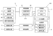
- FIG. 1 is a schematic diagram showing an overall configuration of an X-ray imaging apparatus according to first to fifth embodiments. It is a block diagram of an X-ray imaging apparatus. It is the top view which showed the traveling mechanism typically. It is the side view which showed typically a support
- FIG. 1 shows an example of a ceiling-suspended X-ray imaging apparatus 100 installed in the imaging room 101.
- the X-ray imaging apparatus 100 mainly includes an X-ray tube 1, an X-ray detector 2, and a holding mechanism 3.
- the moving body 4 having the X-ray tube 1 is held by the holding mechanism 3 disposed on the ceiling of the imaging room 101 so as to be suspended from the ceiling.
- the moving body 4 is held by the holding mechanism 3 so as to be movable in the photographing room 101.
- the holding mechanism 3 is an example of the “holding mechanism for an X-ray imaging apparatus” in the claims.
- the X-ray imaging apparatus 100 is a medical X-ray imaging apparatus, and is configured to perform X-ray imaging of a patient K that is an imaging target.
- the X-ray imaging apparatus 100 includes an imaging table 5 for imaging in a posture (standing position) with the patient K lying down, and an imaging stand for performing imaging in a posture (standing position) with the patient K upright. 6 is provided.
- the X-ray detector 2 is movably held on the imaging table 5 and the imaging stand 6, respectively.
- the X-ray detector 2 is constituted by, for example, a flat panel detector (FPD).
- the holding mechanism 3 includes at least a photographing position in the supine position using the photographing table 5 (see the solid line in FIG. 1) and a photographing position in the standing position using the photographing stand 6 (see the two-dot chain line in FIG. 1). It is possible to move the moving body 4 between.
- the moving body 4 In the upright imaging, the moving body 4 is arranged at a position facing the X-ray detector 2 of the imaging table 5 in the vertical direction, and between the X-ray tube 1 and the X-ray detector 2 facing the vertical direction.
- the patient K lying on the imaging table 5 is imaged.
- the moving body 4 In the standing position imaging, the moving body 4 is disposed at a position facing the X-ray detector 2 of the imaging stand 6 in the horizontal direction, and between the X-ray tube 1 and the X-ray detector 2 facing in the horizontal direction.
- the patient K standing up in front of the imaging stand 6 is imaged.
- the X-ray imaging apparatus 100 arranges the portable X-ray detector 2 at an arbitrary position in the imaging room 101 and moves the moving body 4 to a position facing the X-ray detector 2. It is possible to perform general photographing (photographing without specifying a posture) capable of photographing the patient K in the posture from an arbitrary direction.
- the X-ray imaging apparatus 100 includes a control unit 7, a storage unit 8, and an input device 9.
- the control unit 7 mainly includes a CPU (Central Processing Unit) and a memory.
- the control unit 7 performs X-ray imaging control by the X-ray tube 1 and the X-ray detector 2 and control related to the movement of the moving body 4.
- the storage unit 8 stores various data used for X-ray imaging.
- the input device 9 has a function of accepting an input operation related to X-ray imaging.
- the input operation includes setting of imaging conditions for X-ray imaging, an instruction to start X-ray irradiation, and the like.
- the moving body 4 includes an X-ray tube 1 and a collimator 11.
- the X-ray tube 1 generates X-rays when a high voltage is applied from a power source (not shown).
- the collimator 11 has a plurality of shielding plates (collimator leaves) whose positions can be adjusted, and has a function of adjusting an X-ray irradiation field by shielding a part of the X-rays from the X-ray tube 1.
- the moving body 4 is provided with a grip portion 35.
- the moving body 4 is provided with an operation unit 41 including a touch panel or a mechanical switch.
- the holding mechanism 3 includes a moving mechanism 31 that holds the moving body 4 movably in a plurality of directions, and a switching unit 36 that switches between a state in which the movement of the moving body 4 is permitted and a state in which the movement is prohibited in each of the plurality of directions. 2).
- the plurality of directions in which the moving body 4 can be moved by the moving mechanism 31 can include horizontal and vertical translation directions orthogonal to each other. As shown in FIG. 1, when the vertical (vertical) direction is the Z direction, and the two directions orthogonal to each other in the horizontal direction are the X direction and the Y direction (see FIG. 3), the translation directions are X, Y and One or more of the Z directions.
- the plurality of directions in which the moving body 4 can be moved by the moving mechanism 31 can include rotation directions around the horizontal axis and the vertical axis that are orthogonal to each other.
- Each rotation direction is one or more of a rotation direction around a vertical (vertical) axis and a rotation direction around two axes orthogonal to each other in the horizontal direction.
- the plurality of directions include three translational directions (X, Y, and Z directions), a rotational direction around the Z axis ( ⁇ direction, see FIG. 4), and a rotational direction around the R axis in the horizontal direction ( An example including a total of five directions including the ⁇ direction (see FIG. 4) is shown.
- the moving mechanism 31 includes a traveling mechanism 32, a support 33, and a rotation holding unit 34.
- the traveling mechanism 32 is provided on the ceiling of the photographing room 101.
- the traveling mechanism 32 supports the column 33 (moving body 4) so as to be able to translate in the X direction and the Y direction.
- the traveling mechanism 32 includes a pair of fixed rails 32a fixed to the ceiling surface and a pair of movable rails 32b.
- the pair of fixed rails 32a extends linearly in the X direction.
- a pair of movable rails 32b is attached to the pair of fixed rails 32a so as to be movable in the X direction.
- the pair of movable rails 32b extends linearly in the Y direction.
- a base portion 33a of a support column 33 is attached to the pair of movable rails 32b so as to be movable in the Y direction.
- the support column 33 holds the movable body 4 so that it can be translated in the vertical direction.
- the support column 33 is provided so as to be suspended from a base portion 33a (see FIG. 1) attached to the traveling mechanism 32, and can extend and contract in the Z direction.
- the moving mechanism 31 holds the moving body 4 so as to be movable in three translational directions (X, Y, and Z directions).
- a rotation holding part 34 is provided at the tip (lower end) of the support 33.
- the support column 33 supports the rotation holding unit 34 so as to be rotatable and movable in the ⁇ direction around the vertical axis (Z axis).
- the Z axis coincides with the central axis of the column 33.
- the rotation holding portion 34 has a shape in which one end side is connected to the column 33 and the other end side rises upward at a position offset in the radial direction (R-axis direction) of the column 33.
- the rotation holding part 34 supports the moving body 4 by the other end side holding part 34a rising upward.
- the rotation holding portion 34 holds the movable body 4 so as to be rotatable in the ⁇ direction around the horizontal axis (R axis).
- the R axis is the radial direction (horizontal direction) of the support column 33.
- the moving mechanism 31 includes a grip portion 35.
- the grip portion 35 is provided on the moving body 4 and is supported by the rotation holding portion 34 so as to rotate integrally with the moving body 4.
- the grip portion 35 is supported by the support column 33 so as to move integrally with the moving body 4. That is, the grip portion 35 is held by the support column 33 via the rotation holding portion 34 and moves in a plurality of directions (X, Y, Z, ⁇ , ⁇ ) together with the moving body 4.
- the operator can move the moving body 4 in a plurality of directions (X, Y, Z, ⁇ , ⁇ ) by holding the grip portion 35 and applying force.
- the holding mechanism 3 is moved by the switching means 36 among a plurality of directions based on the force detection unit 38 that detects the direction of the force applied to the moving mechanism 31 and the detected direction of the force. And a control unit 7 that determines a direction to be permitted.
- the force detector 38 is an example of the “force direction detector” in the claims.
- the control unit 7 is an example of “permitted direction determining means” and “free mode setting means” in the claims.
- the switching means 36 includes a plurality of lock mechanisms that are provided corresponding to each of a plurality of directions and lock the movement of the moving body 4.
- an electromagnetic lock (electromagnetic brake) 36a is provided as a lock mechanism.
- the electromagnetic lock 36a is an example of the “lock mechanism” in the claims.
- the lock mechanism may be a hydraulic or mechanical brake.
- Each electromagnetic lock 36a is configured to releasably lock the movement of the moving body 4 in each of a plurality of directions.
- the electromagnetic lock 36a is individually provided in a plurality of directions including the X, Y, Z, ⁇ , and ⁇ directions. Each electromagnetic lock 36a can individually switch between locking / unlocking in the X, Y, Z, ⁇ , and ⁇ directions. Accordingly, the switching unit 36 switches between a state in which the movement of the moving body 4 in each of a plurality of directions is permitted (unlocked state) and a state in which the movement of the moving body 4 in each direction is prohibited (locked state). It is configured to be possible.
- the switching means 36 is always maintained in a state in which movement of the moving body 4 in each of a plurality of directions is prohibited. And the switching means 36 is comprised so that it may switch to the state which permits the movement of the mobile body 4 separately about the direction determined by the control part 7. FIG.
- the moving mechanism 31 includes an encoder 37 in each axial direction.
- Each encoder 37 detects the position of the moving body 4 in each axial direction. Based on the output signals of the encoders 37, the current position of the X-ray tube 1 of the moving body 4 (positions in the X, Y, and Z directions and rotation angles in the ⁇ and ⁇ directions) can be obtained. .
- each electromagnetic lock 36a is controlled by the control unit 7 via the drive circuit 31a.
- the output signal of each encoder 37 is sent to the control unit 7 via the drive circuit 31a, and is used for operation control as position information.
- the force detector 38 detects the direction of the force applied to the moving mechanism 31. More specifically, the force detection unit 38 is configured to detect forces in the horizontal and vertical translational directions (X, Y, and Z directions) applied to the grip unit 35. The force detection unit 38 is configured to detect the force applied to the gripping unit 35 in each rotational direction ( ⁇ , ⁇ direction) about the horizontal axis (R axis) and the vertical axis (Z axis). Yes.
- the force detection unit 38 is disposed between the gripping unit 35 and the rotation holding unit 34.
- the force detection unit 38 is configured by a force meter, for example.
- the component force meter can detect each direction component of the force applied to the detection surface and measure the direction of the force and the magnitude of the force.
- the force detection unit 38 functions as a force direction detection unit that detects the direction of the force applied to the moving mechanism 31.
- the force detection unit 38 is disposed between the gripping unit 35 and the rotation holding unit 34 at a connection location between the moving body 4 and the other end side holding unit 34 a.
- the force detection unit 38 is disposed at a connection point between the moving body 4 and the holding mechanism 3 (the moving mechanism 31).
- the force detection unit 38 is provided so that the center of the detection surface is positioned on the R axis.
- the detection center of the force detection unit 38 and the rotation center of the gripping unit 35 are coaxial on the R axis.
- the force detection unit 38 is mechanically coupled to the grip unit 35 and can detect the force in each direction applied to the grip unit 35. Further, the force detection unit 38 can detect the force in the translational direction of the three orthogonal axes and the moment around each axis.
- the force detection unit 38 detects, for example, six components of three-axis forces (Sx, Sy, Sz) and moments around the Sx, Sy, and Sz axes. It is configured as follows.
- the Sz axis of the force detection unit 38 coincides with the R axis and passes through the rotation center of the gripping unit 35.
- the detection surface (Sx-Sy plane) of the force detection unit 38 and the front surface of the gripping unit 35 are substantially parallel.
- the force that grips the gripping part 35 and pushes it in each direction of the Sx, Sy, and Sz axes is detected by the force detection part 38 as a force in the Sx, Sy, and Sz axis directions.
- a force that grips the gripping part 35 and rotates it in the ⁇ direction (around the R axis) is detected by the force detection part 38 as a moment around the Sz axis.
- the force that grips the grip 35 and rotates it in the ⁇ direction (around the Z axis) is detected by the force detector 38 as a moment around the Sx axis.
- the detection result of the force detection unit 38 (the magnitude of the force in the translational direction of the three orthogonal axes and the magnitude of the moment around each axis) is acquired by the control unit 7.
- the control unit 7 acquires the direction ( ⁇ direction, ⁇ direction) of the moving body 4 (gripping unit 35) based on the output signal of each encoder 37. Based on the direction of the moving body 4 (gripping unit 35) and the direction of the force detected by the force detection unit 38 (Sx, Sy, Sz axis directions and rotation directions around each axis), the control unit 7 The force and moment applied to the moving direction (X, Y, Z, ⁇ , ⁇ ) are acquired. And the control part 7 determines the direction which permits a movement by the switching means 36 (electromagnetic lock 36a) among several directions (X, Y, Z, (eta), (theta)) based on the direction of the detected force.
- the switching means 36 electromagagnetic lock 36a
- the control unit 7 controls the electromagnetic lock 36a so as to release the lock in the direction of the force detected by the force detection unit 38 among the plurality of directions. Thereby, the control unit 7 functions as a permission direction determining unit that determines a direction in which the movement of the moving body 4 is permitted. Thus, the control unit 7 is configured to perform automatic determination control that determines a direction in which movement is permitted based on the direction of the force detected by the force detection unit 38.
- the switching between the locked state and the unlocked state can be performed in addition to the method of automatically switching when the operator applies a force to the grip portion 35.
- the operation unit 41 provided in the grip unit 35 is for individually switching between a locked state and an unlocked state in each of a plurality of directions (X, Y, Z, ⁇ , ⁇ ).
- Each operation switch 41a is provided.
- the control unit 7 can perform manual determination control for determining a direction in which movement of the moving body 4 is permitted based on an input operation of each operation switch. Even in the case of manual determination control, the control unit 7 can individually switch the lock state and the unlock state of the electromagnetic lock 36a in each direction.
- the control unit 7 functions as a free mode setting unit that allows the moving body 4 to move in all directions in a plurality of directions by the electromagnetic lock 36a based on an operator's setting operation.
- the operation unit 41 is provided with a free mode switch 42.
- the control unit 7 receives an input operation of the free mode switch 42, the control unit 7 starts free mode control for switching all the electromagnetic locks 36a to the unlocked state.
- the operator can grip the grip portion 35 and freely move the moving body 4 in a plurality of directions (X, Y, Z, ⁇ , ⁇ ).
- the control unit 7 causes the electromagnetic lock 36a to perform a multi-directional operation based on the time setting after the operator cancels the setting cancellation operation or the multi-directional movement in all directions. Switch to a state that prohibits movement in all directions.
- a multi-directional operation for example, when the free mode switch 42 is input once and the mode is shifted to the free mode, the free mode switch 42 is input again, or a dedicated release switch (not shown) is input. Is included.
- the elapsed time can be, for example, several seconds after the start of the free mode, for example 5 seconds.
- step S1 the control unit 7 acquires the detection result of the force detection unit 38.
- the force is detected by the force detector 38.
- the control unit 7 acquires the direction (X, Y, Z, ⁇ , ⁇ ) of the force applied by the operator from the detection result of the force detection unit 38 and the detection result of the encoder 37.
- step S2 the control unit 7 determines a direction in which movement is permitted by the switching means 36 (electromagnetic lock 36a) based on the direction of the force detected in step S1. Specifically, the control unit 7 moves the direction of the detected force when a force in one or a plurality of directions (X, Y, Z, ⁇ , ⁇ ) is detected. It is determined as the permitted direction (moving direction).
- step S3 the control unit 7 switches to a state in which the movement of the moving body 4 in the determined movement direction is permitted. That is, the control unit 7 switches the electromagnetic lock 36a corresponding to the determined moving direction from the locked state to the unlocked state. Thereby, the operator can move the moving body 4 in the detected moving direction. On the other hand, the control part 7 leaves the electromagnetic lock 36a corresponding to directions other than the determined moving direction among multiple directions (X, Y, Z, (eta), (theta)) in a locked state.
- step S4 the control unit 7 determines whether or not to end the movement permission. For example, the control unit 7 maintains a state in which the movement is permitted while the force is detected by the force detection unit 38. If there is no moving direction to end the movement permission, the control unit 7 repeats steps S1 to S3. If a force by the operator is no longer detected after switching to a state in which movement is permitted for a certain movement direction, the movement direction is excluded from the direction in which movement is permitted in step S2. In this case, in step S4, the control unit 7 determines to end the movement permission, and proceeds to step S5.
- step S5 the control unit 7 switches the movement direction for ending the movement permission to a state in which movement is prohibited. That is, the control unit 7 switches the electromagnetic lock 36a from the unlocked state to the locked state. Then, the control part 7 returns a process to step S1.
- a plurality of directions (X, Y, Z, ⁇ , ⁇ ) is provided with a control unit 7 for determining a direction in which movement is permitted by the switching means 36.
- the control unit 7 can enter a state of permitting movement in the direction in which the force is applied.
- the operator is automatically permitted to move in the moving direction only by applying a force in the direction (moving direction) in which the moving body 4 is desired to move without requiring a switch operation or the like.
- the moving body 4 can be moved by switching to the above. Thereby, the operativity at the time of moving the mobile body 4 for X-ray imaging can be improved. And when aligning the mobile body 4, since an operator does not need to move a eyes
- the force detection unit 38 that detects the force in the vertical direction (Z direction) applied to the grip unit 35 is provided.
- the operator can permit the movement in the vertical direction by the operation of moving the moving body 4 in the vertical direction while holding the grip portion 35, and moves the moving body 4 in the vertical direction as it is to perform alignment. Therefore, the operability can be further improved.
- the force detection unit 38 that detects the forces in the horizontal and vertical translational directions (X, Y, Z) applied to the grip unit 35 is provided.
- the operator moves in the X, Y, and Z directions, the operator can permit movement in the moving direction only by holding the grip portion 35 and applying force, and the moving body 4 can be translated as it is. Therefore, the operability can be further improved.
- the force detection unit 38 that is disposed between the gripping unit 35 and the support column 33 and that can detect forces in the three orthogonal axes is provided.
- an apparatus structure can be simplified.
- the force detection unit 38 that detects the force in the rotation direction ( ⁇ ) around the horizontal axis (R axis) applied to the gripping unit 35 is provided.
- the operator can move the movable body 4 in the rotational direction around the horizontal axis by moving the gripping part 35 around the horizontal axis, and can adjust the position as it is. Can be further improved.
- the operator moves the movable body 4. Since the moving body 4 can be rotated and moved simply by applying a force in the desired direction, an intuitive operation is possible regardless of the direction of the moving body 4. In this respect, the operability is improved.
- a detection unit 38 is provided. Thereby, in any rotation direction, the operator can rotate and move the movable body 4 as it is simply by holding the grip 35 and applying force. As a result, operability can be further improved.
- the force detection unit 38 that is disposed between the gripping unit 35 and the rotation holding unit 34 and can detect moments around a plurality of orthogonal axes is provided.
- an apparatus structure can be simplified.
- the force detection unit 38 capable of detecting the force in the translational direction of the three orthogonal axes and the moment around each axis is provided.
- the common force detection unit 38 can detect the force in each moving direction and allow the movement. Therefore, even in a configuration capable of movement in multiple directions, it is not necessary to provide a force detection unit individually for each movement direction, so that the device configuration can be extremely simplified.
- the control unit 7 can be set to a free mode in which the movement of the moving body 4 in all directions in a plurality of directions is permitted by the electromagnetic lock 36a based on the setting operation by the operator. Is provided. Thereby, after obtaining the operator's setting operation, the moving body 4 can be shifted to a free mode in which the user can freely move. For example, after roughly aligning the moving body 4 in the free mode, it is possible to perform only position adjustment in a specific moving direction by automatic determination control, and usability can be further improved.
- the control unit 7 switches the switching unit 36 based on the setting cancellation operation by the operator or the passage of time after allowing the movement in all directions in a plurality of directions. To switch to a state in which movement in all directions in a plurality of directions is prohibited. Accordingly, it is possible to easily distinguish between the movement permission in the free mode and the movement permission based on the detected force direction.
- the switching unit 36 is always in a state (locked state) in which the movement of the moving body 4 is prohibited in each of a plurality of directions (X, Y, Z, ⁇ , ⁇ ). It maintains so that it may switch to the state (lock release state) which permits the movement of the mobile body 4 about the direction determined by the control part 7 separately. Thereby, even when the movement of the moving body 4 in the direction of the force applied by the operator is permitted, the movement of the moving body 4 in the direction not intended by the operator can be suppressed.
- the switching unit 36 is provided with a plurality of electromagnetic locks 36 a provided corresponding to each of a plurality of directions and locking the movement of the moving body 4, and is determined by the control unit 7.
- the lock of the electromagnetic lock 36a corresponding to the direction is released. Thereby, it is possible to easily maintain only the movement in the direction determined by the control unit 7 and prohibit the movement in the other direction.
- the holding mechanism 3 includes force intensity detecting means for detecting the magnitude of the force applied to the moving mechanism 31.
- the holding mechanism 3 includes assist means that applies an assist force toward the moving direction of the moving body 4 to the moving body 4 based on the magnitude of the detected force.
- the holding mechanism 3 includes a plurality of motors (111 to 115), and the assist means is configured by the control unit 7 and the motor.
- the force detector 38 (see FIG. 4) of the holding mechanism 3 also functions as a force intensity detector. That is, the force direction detection means and the force intensity detection means are integrally configured by a force detection unit 38 that detects the direction of the force and the magnitude of the force.
- the configuration of the force detection unit 38 is the same as that in the first embodiment.
- the travel mechanism 32 includes an X-axis motor 111 and an X-axis transmission mechanism 121.
- the X-axis transmission mechanism 121 includes a pair of rollers (pulleys) 121a disposed near both ends of the fixed rail 32a and a timing belt 121b spanned between the pair of rollers 121a. Including a belt-pulley mechanism.
- a pair of movable rails 32b are fixed to the timing belt 121b, and the X-axis motor 111 rotationally drives the roller 121a, thereby applying assist force in the X direction to the pair of movable rails 32b (moving body 4). To do.
- the traveling mechanism 32 includes a Y-axis motor 112 and a Y-axis transmission mechanism 122 as shown in FIG.
- the Y-axis transmission mechanism 122 is a belt-pulley mechanism including a pair of rollers 122a and a timing belt 122b, as shown in FIG. 10, as with the X-axis transmission mechanism 121, for example.
- the base portion 33a of the support 33 is fixed to the timing belt 122b, and the Y-axis motor 112 rotationally drives the roller 122a to apply assist force in the Y direction to the support 33 (moving body 4).
- the column 33 (see FIG. 1) includes a Z-axis motor 113 and a Z-axis transmission mechanism 123.
- the Z-axis transmission mechanism 123 is, for example, a winding mechanism including a wire 123a (see FIG. 1) connected to the rotation holding unit 34 at the lower end of the support column 33.
- the Z-axis motor 113 winds and drives the wire 123a, thereby applying an assist force in the Z direction to the rotation holding unit 34 (moving body 4).
- the support column 33 (see FIG. 4) includes an ⁇ -axis motor 114 that rotationally drives the rotation holding unit 34 around the Z-axis.
- the ⁇ -axis motor 114 does not need to be directly connected to the rotation holding unit 34, and a ⁇ -axis transmission mechanism 124 (see FIG. 9) such as a speed reducer may be provided.
- the ⁇ -axis motor 114 applies assist force in the ⁇ direction to the rotation holding unit 34 (moving body 4).
- the rotation holding unit 34 includes a ⁇ -axis motor 115 that rotates the movable body 4 around the R axis in the other end side holding unit 34a.
- the ⁇ -axis motor 115 does not need to be directly connected to the moving body 4, and a ⁇ -axis transmission mechanism 125 (see FIG. 9) such as a speed reducer may be provided.
- the ⁇ -axis motor 115 applies assist force to the moving body 4 in the ⁇ direction.
- each motor (X-axis motor 111, Y-axis motor 112, Z-axis motor 113, ⁇ -axis motor 114, ⁇ -axis motor 115) has an encoder 37 and switching means 36 (each electromagnetic Lock 36a) is connected.
- each motor (X-axis motor 111, Y-axis motor 112, Z-axis motor 113, ⁇ -axis motor 114, ⁇ -axis motor 115) and each electromagnetic lock 36a is controlled by the control unit 7 via the drive circuit 31a. Is done.
- the output signal of each encoder 37 is sent to the control unit 7 via the drive circuit 31a, and is used for operation control as position information.
- the control unit 7 is configured to apply an assist force in the moving direction of the moving body 4 to the moving body 4 based on the magnitude of the force detected by the force detecting unit 38.
- the control unit 7 moves by control that individually drives motors (X-axis motor 111, Y-axis motor 112, Z-axis motor 113, ⁇ -axis motor 114, and ⁇ -axis motor 115) corresponding to the direction in which the assist force is applied.
- An assist force toward the moving direction of the body 4 is generated.
- control unit 7 is configured to apply to the moving body 4 an assist force having a magnitude corresponding to the magnitude of the detected force.
- FIG. 11 shows the magnitude (horizontal axis) of the force (detection force) detected by the force detection unit 38 when the operator applies a force to the gripping unit 35, and the assist force (vertical axis) generated. An example of the relationship is shown.
- the control unit 7 controls each motor so that a larger assist force is generated as the detected force increases.
- the control unit 7 generates an assist force proportional to the detected force in part or all of the assist control.
- the assist force may be simply proportional to the detection force, or an upper limit value Fm of the assist force is set so that the assist force does not exceed the upper limit value Fm. It may be.
- control unit 7 may start assist control for applying an assist force when a force equal to or greater than the first threshold Th1 is detected. Thereby, it can suppress that the mobile body 4 moves largely contrary to an operator's intention.
- control part 7 may stop the assist control which provides assist force, when the detected force falls below 2nd threshold value Th2 after the start of assist control. At this time, it is preferable to make the second threshold Th2 smaller than the first threshold Th1. In this case, the operator can receive assist until immediately before stopping the moving body 4 having a large weight, so that the positioning of the moving body 4 is facilitated.
- step S11 the control unit 7 acquires the detection result (force direction and magnitude) of the force detection unit 38.
- step S ⁇ b> 12 the control unit 7 acquires the direction and magnitude of the force applied by the operator from the detection result of the force detection unit 38 and the detection result of the encoder 37.
- the following processing after step S13 is performed individually for each of a plurality of directions (X, Y, Z, ⁇ , ⁇ ). Here, for convenience, processing for any one direction will be described.
- step S13 the control unit 7 determines whether to start assist based on the magnitude of the force acquired in step S12. That is, the control unit 7 determines whether or not the magnitude of the force in the movement direction to be determined is equal to or greater than the first threshold Th1.
- the controller 7 switches the electromagnetic lock 36a corresponding to the moving direction to the unlocked state in step S14, and starts assist driving in step S15.
- the control unit 7 drives a motor (any one of the X-axis motor 111, the Y-axis motor 112, the Z-axis motor 113, the ⁇ -axis motor 114, and the ⁇ -axis motor 115) corresponding to the direction in which the assist force is applied, and the moving direction. Generate assist power to At this time, as shown in FIG. 11, the control unit 7 generates assist force so as to be proportional to the magnitude of the force in the moving direction. After the assist starts, the process returns to step S11.
- step S13 when the magnitude of the force in the movement direction to be determined is less than the first threshold Th1 in step S13, the control unit 7 advances the process to step S16.
- step S16 the control unit 7 determines whether to stop the assist or to maintain the current state based on the magnitude of the force in the moving direction to be determined. That is, the control unit 7 determines whether or not the magnitude of the force is equal to or less than the second threshold Th2. When the magnitude of the force applied to the operator does not become equal to or less than the second threshold Th2 (when it exceeds the second threshold Th2), the control unit 7 continues the current state. That is, if the assist is being performed (a state in which movement is permitted), the assist is continued. If the assist is being stopped (a state in which movement is prohibited), the assist stop state is continued.
- control unit 7 stops assist driving of the corresponding motor in step S17, and switches the corresponding electromagnetic lock 36a to the locked state in step S18.
- the control unit 7 determines a direction in which movement is permitted by the switching unit 36 among a plurality of directions. The operability when moving the moving body 4 for X-ray imaging can be improved.
- the force detection unit 38 that detects the magnitude of the force applied to the moving mechanism 31 and the moving direction of the moving body 4 based on the detected magnitude of the force.
- a control unit 7 that applies an assisting force toward the moving body 4 to the moving body 4.
- the force detection unit 38 that detects the force in the vertical direction (Z direction) applied to the grip unit 35 is provided. As a result, it is possible to perform power assist only by the operator performing the operation of moving the moving body 4 in the vertical direction while holding the grip portion 35, so that the operability can be further improved.
- the force detection unit 38 that detects the forces in the horizontal and vertical translational directions (X, Y, and Z directions) applied to the grip unit 35 is provided.
- the power assist in each direction can be started by a common operation in which the operator holds the grip portion 35 and applies force in the moving direction, so that the operability can be further improved.
- the force detection unit 38 that detects the force in the rotation direction ( ⁇ direction) around the horizontal axis applied to the grip unit 35 is provided.
- the operator can perform power assist only by performing the operation of rotating the grip portion 35 around the horizontal axis, and thus the operability can be further improved.
- the force detection unit 38 that detects the force applied to the gripping unit 35 in the rotation directions ( ⁇ and ⁇ directions) around the horizontal axis and the vertical axis is provided.
- the power assist can be started by a common operation that only applies force in the rotational movement direction, so that the operability can be further improved.
- the force direction detection means and the force intensity detection means are integrally configured by the force detection unit 38 that detects the direction of the force and the magnitude of the force.
- control unit 7 is configured to apply the assist force having a magnitude corresponding to the magnitude of the detected force to the moving body 4.
- the X-ray imaging apparatus 100 (holding mechanism 3) further includes an operator detection unit 210 that detects an operator.
- the operator detection unit 210 is configured by, for example, a contact sensor 211 that detects that the grip portion 35 is gripped by the operator.
- a contact sensor 211 various methods such as a capacitive sensor and a piezoelectric sensor using a piezoelectric film can be adopted.
- the contact sensor 211 is provided, for example, over a predetermined range of the grip portion 35 and detects contact of an operator's finger with the grip portion 35.
- FIG. 13 shows an example in which the contact sensor 211 is provided over substantially the entire gripping portion 35 (hatched portion in FIG. 13).
- the operator detection unit 210 is, for example, a communication unit 212 capable of wireless communication with the communication unit CM held by the operator.
- the communication unit 212 is provided in the grip unit 35 and the operation unit 41, for example, and performs bidirectional communication with the communication unit CM by short-range wireless communication.
- the communication means CM is a communication device carried by the operator, an authentication terminal capable of communication, and other devices.
- the control unit 7 can detect the operator via the communication unit 212. In two-way communication, personal authentication may be performed including operator authentication information. In FIG. 13, both the contact sensor 211 and the communication unit 212 are illustrated for convenience, but only one of the contact sensor 211 and the communication unit 212 may be provided.
- the control unit 7 prohibits the movement of the moving body 4 by the switching unit 36 (electromagnetic lock 36a) when the operator is not detected by the operator detection unit 210.
- the control unit 7 determines a direction in which the movement is permitted by the switching unit 36 (electromagnetic lock 36a). That is, when a force in the movement direction is detected by the force detection unit 38 with the operator being detected, the control unit 7 switches the electromagnetic lock 36a corresponding to the movement direction to the unlocked state.
- the control unit 7 determines a direction in which movement is permitted by the switching unit 36 among a plurality of directions. The operability when moving the moving body for X-ray imaging can be improved.
- the operator detecting unit 210 that detects the operator is provided, and the control unit 7 switches the switching unit 36 when the operator is not detected by the operator detecting unit 210.
- the switching unit 36 determines the direction in which the movement is permitted. Thereby, even if it is the structure which permits the movement of the mobile body 4 automatically based on the applied force, it prevents that an operator intends a movement (the mobile body 4 moves). be able to.
- the operator detection means 210 (contact sensor 211) for detecting that the grip portion 35 is gripped by the operator is provided. Thereby, the operator can be detected easily and reliably by using the gripping portion 35 by the operator when moving the moving body 4.
- the communication unit 212 capable of wireless communication with the communication unit CM held by the operator is provided, and the control unit 7 detects the operator via the communication unit 212.
- the control unit 7 detects the operator via the communication unit 212.
- the moving mechanism 31 includes engaging means 310 that releasably engages with the moving mechanism 31 to stop the moving body 4 at a predetermined position.
- the engaging means 310 includes a stopper mechanism 311 provided on the moving side and an engaging portion 321 provided on the fixed side.
- the engaging means 310 can be provided in each of the moving mechanism portions in a plurality of directions (X, Y, Z, ⁇ , ⁇ ).
- FIG. 14 shows a configuration example of the engaging means 310 for the Y-direction movement of the base portion 33a with respect to the movable rail 32b.
- the movable rail 32b becomes the fixed side and the base portion 33a becomes the moving side.
- an engaging portion 321 is formed at a predetermined position P1.
- the engagement part 321 is an engagement hole, for example.
- the base portion 33 a is provided with a stopper mechanism 311 that can engage with the engaging portion 321.
- the stopper mechanism 311 is, for example, a solenoid pin that can advance and retract toward the engagement hole.
- the pin 312 In the stopper mechanism 311, the pin 312 is biased toward the engagement hole, and when the base portion 33 a moves in the Y direction and reaches the predetermined position P ⁇ b> 1, the pin 312 enters the inside of the engagement portion 321. The base part 33a is stopped. As a result, the movement of the moving body 4 in the Y direction is stopped at the predetermined position P1.
- the controller 7 can release the engagement between the stopper mechanism 311 and the engaging portion 321 by driving the solenoid 313 of the stopper mechanism 311 and pulling the pin 312.
- the predetermined position P1 is set to a position that becomes a reference position of the X-ray tube 1 when X-ray imaging is performed.
- the X-ray tube 1 is arranged on the center line of the X-ray detector 2 provided in the imaging table 5 in the X direction and the Y direction. It is a position.
- the Z direction is a position where the distance (SID) between the focal point of the X-ray tube 1 and the detection surface of the X-ray detector 2 is a predetermined reference distance.
- the R axis is an angular position where the Y axis coincides with the Y direction, and for the ⁇ direction, the X-ray optical axis (the direction of the collimator 11) coincides with the Z direction downward. Therefore, when the movable body 4 is moved to a predetermined position (reference position), the fixed rail 32a (X direction), the movable rail 32b (Y direction), the support 33 (Z direction, ⁇ direction), and the other end side holding portion 34a ( The movable body 4 is positioned at a predetermined position by each engaging means (not shown) provided in the ⁇ direction.
- the switching unit 36 switches to a state in which the movement of the moving body 4 is prohibited when the moving mechanism 31 is engaged with the engaging unit 310. That is, for each moving direction, when the movement of the moving body 4 is stopped by the engaging means 310, the corresponding electromagnetic lock 36a is switched to the locked state by the control unit 7.
- control unit 7 determines the direction in which the movement is permitted by the electromagnetic lock 36a and releases the engagement between the moving mechanism 31 and the engaging means 310.
- the control unit 7 when the moving body 4 moves toward the predetermined position P1, the control unit 7 decreases the assist force applied to the moving body 4 as the moving body 4 approaches the predetermined position P1.
- the control unit 7 when the moving direction is a direction approaching the predetermined position P1, the control unit 7 assists as the distance between the current position and the predetermined position P1 decreases. Reduce power.
- the control unit 7 may control the assist force so that the assist force is proportional to the distance between the current position and the predetermined position P1, or the assist force is inversely proportional to the distance. You may control as follows.
- the engagement means 310 that engages with the moving mechanism 31 in a releasable manner and stops the moving body 4 at the predetermined position P1 is provided.
- the control unit 7 is configured to determine a direction in which movement is permitted by the switching unit 36 and to release the engagement between the moving mechanism 31 and the engagement unit 310.
- the movable body 4 can be positioned easily and quickly by the engaging means 310. Even when the engaging means 310 is provided, the operator can release the engagement of the engaging means 310 only by applying a force to the moving mechanism 31, so that the positioning of the moving body 4 is facilitated. Can be improved.
- the control unit 7 assists the moving body 4 as the moving body 4 approaches the predetermined position P1. Configure to reduce the force. Thereby, even when performing power assist, the moving body 4 is less likely to move (assist force is reduced) and the moving speed can be reduced as the position approaches the predetermined position P1, so that the moving speed can be lowered with the engagement means 310 at the predetermined position P1. The impact when engaging the body 4 can be reduced.
- control part 7 is comprised so that control regarding the movement of the mobile body 4 may be switched. Specifically, the control unit 7 performs automatic determination control for determining a direction in which movement is permitted based on the direction of the detected force, and manual determination for determining a direction in which movement is permitted based on an operation input by the operator. Switch between control.
- the storage unit 8 stores a plurality of imaging technique and imaging site preset information (8a, 8b) in advance.
- the imaging technique includes, for example, supine shooting, standing shooting, and general shooting.
- the photographing technique may include a technique other than the standing position photographing, the standing position photographing, and the general photographing.
- the imaging region is a region to be imaged in X-ray imaging, and includes various anatomical regions such as the chest, upper arm, fingers, clavicle, and cervical spine.
- the imaging technique and imaging region can be selected by the operator operating the input device 9.
- imaging conditions are set in advance for each imaging technique and imaging region.
- the storage unit 8 stores preset information 8c of a reference position when performing X-ray imaging for each imaging technique and each imaging region.
- the control unit 7 obtains the selected imaging technique information 401 and imaging part information 402 (information on the selected imaging technique and imaging part) via the input device 9.
- the control unit 7 is configured to switch between automatic determination control and manual determination control in accordance with the imaging technique information 401.
- the control unit 7 is configured to switch between automatic determination control and manual determination control in accordance with the imaging part information 402 (selected imaging part).
- the control unit 7 performs automatic determination control when the acquired imaging technique information 401 is a predetermined imaging technique. Thereby, the operator can release the switching means 36 (electromagnetic lock 36a) and move the moving body 4 simply by gripping the grip portion 35 and applying a force in the direction in which the moving body 4 is desired to move. Can do.
- the control unit 7 performs manual determination control without performing automatic determination control. In this case, the control unit 7 releases the switching unit 36 (electromagnetic lock 36a) corresponding to the moving direction designated by the operator in accordance with the input operation of the operation unit 41.
- the control unit 7 acquires the reference position P2 of the moving body 4 in a predetermined photographing technique.
- the reference position P2 is acquired based on preset information 8c regarding the reference position in the storage unit 8.
- the control part 7 moves based on the direction of the detected force about the moving direction in which the present position P3 of the moving body 4 differs from the reference position P2 in a plurality of directions in automatic determination control.
- the movement of the body is permitted, and the movement of the moving body 4 is prohibited in the moving direction in which the current position P3 of the moving body 4 coincides with the reference position P2.
- the reference position P2 is a position away from the photographing stand 6 by a predetermined distance in the front direction (X direction).
- the control unit 7 performs automatic determination control when the imaging region information 402 is a predetermined imaging region, and performs manual determination control when the imaging region information 402 is other than the predetermined imaging region. For example, when the predetermined imaging region is a finger, the control unit 7 performs automatic determination control when the acquired imaging region information 402 is a finger.
- the control unit 7 acquires the reference position P2 of the moving body 4 in a predetermined imaging region. Then, in the automatic determination control, the control unit 7 permits the movement of the moving body 4 based on the detected force direction for a moving direction in which the current position P3 of the moving body 4 is different from the reference position P2 among a plurality of directions. The moving body 4 is prohibited from moving in the moving direction in which the current position P3 of the moving body 4 coincides with the reference position P2.
- the reference position P ⁇ b> 2 is a position away from the photographing stand 6 by a predetermined distance L in the front direction (X direction).
- the reference position is not set because there are individual differences in height.
- the control unit 7 prohibits movement in the Y direction and allows movement in the X direction. That is, the control unit 7 keeps the electromagnetic lock 36a in the Y direction in the locked state even when a force in the Y direction is detected.
- the electromagnetic lock 36a corresponding to the X direction is switched to the unlocked state, the movement is permitted, and the assist control is started.
- a force detection unit 38 and a control unit 7 that determines a direction in which movement is permitted by the switching unit 36 are provided, so that a moving body for X-ray imaging is provided.
- the operability when moving 4 can be improved.
- the control unit 7 is configured to switch between automatic determination control and manual determination control in accordance with the imaging technique information 401.
- the type of imaging technique for example, for a predetermined imaging technique that needs to move the moving body 4 in an arbitrary direction, automatic determination control is performed, and other imaging techniques that do not need to be moved in an arbitrary direction.
- control switching such as manual determination control is possible.
- the control for determining the direction in which the moving body 4 is permitted to be moved can be appropriately used according to the purpose of the operator, so that the usability can be further improved.
- the moving body is based on the direction of the detected force for the moving direction in which the current position P3 of the moving body 4 is different from the reference position P2 among the plurality of directions. 4 is permitted, and the control unit 7 is configured to prohibit the movement of the moving body 4 in the moving direction in which the current position P3 of the moving body 4 coincides with the reference position P2. Thereby, even when automatic determination control is performed, the moving body 4 can be easily moved to the reference position P2 set according to the imaging technique.
- the control unit 7 is configured to switch between automatic determination control and manual determination control according to the imaging region information 402.
- the imaging region for example, automatic determination control is performed for a predetermined imaging region that needs to move the moving body 4 in an arbitrary direction, and manual determination control is performed for an imaging region that does not need to be moved in an arbitrary direction
- Control switching such as performing can be performed.
- the control for determining the direction in which the moving body 4 is permitted to be moved can be appropriately used according to the purpose of the operator, so that the usability can be further improved.
- the moving body is based on the direction of the detected force for the moving direction in which the current position P3 of the moving body 4 is different from the reference position P2 among the plurality of directions. 4 is permitted, and the control unit 7 is configured to prohibit the movement of the moving body 4 in the moving direction in which the current position P3 of the moving body 4 coincides with the reference position P2. Thereby, even when automatic determination control is performed, the moving body 4 can be easily moved to the reference position P2 set according to the imaging region.
- the configurations shown in the first to fifth embodiments may be combined with each other. Therefore, one or more of the third to fifth embodiments may be combined with the first embodiment or the second embodiment. All the configurations of the first to fifth embodiments may be combined.
- the present invention is not limited to this.
- structures other than a ceiling suspension type may be sufficient.
- the present invention may be applied to a floor-traveling X-ray imaging apparatus 500 (floor-traveling holding mechanism 503).
- the moving body 4 is supported by the holding mechanism 503 disposed on the floor surface of the imaging room 101.
- the moving mechanism 431 of the holding mechanism 503 is movable in the Z direction with respect to the traveling mechanism 432 that travels in the X direction on the rail 450 on the floor surface, the column 433 that extends upward from the traveling mechanism 432, and the column 433.
- the arm 435 is configured to be extendable and contractible in the X direction, and supports the moving body 4 via a rotation holding portion 434 at the tip portion.
- the rotation holding unit 434 supports the moving body 4 so as to be rotatable in the ⁇ direction around the R axis.
- the moving body 4 is provided with an X-ray tube 1 and a collimator 11.
- the present invention is applied to the X-ray imaging apparatus 500 (holding mechanism 503) having such a configuration, and a force detection unit 38 and a control unit that determines the unlocking direction by the switching unit 36 based on the detected direction of the force. 7 may be provided.
- the present invention may be applied to a cart-type X-ray imaging apparatus (holding mechanism) having wheels.
- the present invention is not limited to this.
- the X-ray detector 2 is provided in the moving body 4, and the moving mechanism for moving the X-ray detector is configured to determine the unlocking direction based on the direction of the detected force. May be.
- the moving mechanism 31 movably holds the moving body 4 in a plurality of directions in five axis directions (X, Y, Z, ⁇ , ⁇ ) is shown.
- the present invention is not limited to this.
- the moving mechanism only needs to hold the moving body in a plurality of directions so as to be movable, and may be in a plurality of directions other than the five directions.
- the moving mechanism 31 is configured by the gantry mechanism having three orthogonal axes (X, Y, Z) and the rotating mechanism around the orthogonal axes has been described. Is not limited to this.
- the moving mechanism for moving the moving body may have any structure.
- the moving mechanism may be configured by multi-joint arms, and the moving body may be moved by rotation at each joint and expansion / contraction of the arm between the joints.
- the force detector 38 is provided with a component force meter capable of detecting six components of three orthogonal axes (X, Y, Z) and moments around each axis.
- a force detector other than the force meter may be provided.
- the force detection unit may use a pressure measurement method such as atmospheric pressure or fluid pressure, a method using elasticity such as a spring, a magnetostrictive load cell, a strain gauge, or the like.
- a plurality of force detection units may be provided.
- a force detector may be provided for each movable axial direction.
- each of the transmission mechanisms 121 to 125 shown in FIG. 5 may be provided with a force detection unit that detects a force in the moving direction.
Abstract
このX線撮影装置用保持機構(3)は、X線管(1)またはX線検出器(2)を有する移動体(4)の移動を許可する状態と移動を禁止する状態とを切り替える切替手段(36)と、移動機構(31)に加えられた力の方向を検出する力方向検出手段(38)と、検出された力の方向に基づいて、複数方向のうち切替手段により移動を許可する方向を決定する許可方向決定手段(7)とを備える。
Description
この発明は、X線撮影装置用保持機構およびX線撮影装置に関し、特に、X線管またはX線検出部を移動可能に保持する移動機構を備えたX線撮影装置用保持機構およびX線撮影装置に関する。
従来、X線管またはX線検出部を移動可能に保持する移動機構を備えたX線撮影装置が知られている。このようなX線撮影装置は、たとえば、国際公開第2012/043033号に開示されている。
上記国際公開第2012/043033号に開示されているX線撮影装置は、X線管装置と、操作ハンドルとを備えたヘッド部(移動体)と、ヘッド部を移動可能に保持する移動機構と、移動機構によるヘッド部の移動を固定するロック機構部と、ロック機構部を制御する制御装置とを備えている。移動機構は、水平方向および垂直方向の直交3軸方向と、垂直方向の軸回りの回転方向と、水平方向の軸回りの回転方向との、5軸方向にヘッド部を移動可能に保持している。ロック機構部は、5軸方向の各々におけるヘッド部の移動を個別にロックおよびロック解除することができる。操作ハンドルに、各軸方向に対応する複数のロック解除スイッチが設けられており、操作者がいずれかの軸方向のロック解除スイッチを操作すると、対応する軸方向のロックが制御装置により解除される。
撮影対象者(患者)のX線撮影を行う際、操作者は、ロックを解除した状態でヘッド部を移動させてX線管装置の位置合わせを行い、ロック状態で撮影を行う。
上記国際公開第2012/043033号のX線撮影装置では、移動体(ヘッド部)を移動させる際にロック解除スイッチを操作する必要があり、操作が煩雑である。特に、移動体の位置合わせを行う際に、操作者が撮影位置からロック解除スイッチに視線を移動させる必要があるため、ユーザビリティ(ユーザの使いやすさや使い勝手)が良好でない。また、たとえば移動体を水平軸回りに回転させた場合、回転の前後でロック解除スイッチの位置も水平軸回りに回転移動してしまうため、直感的な操作が行えない。そのため、移動体を移動させる際の操作性を改善することが望まれている。
この発明は、上記のような課題を解決するためになされたものであり、この発明の1つの目的は、X線撮影のために移動体を移動させる際の操作性を改善することが可能なX線撮影装置用保持機構およびX線撮影装置を提供することである。
上記目的を達成するために、この発明の第1の局面におけるX線撮影装置用保持機構は、X線管またはX線検出器を有する移動体を複数方向に移動可能に保持する移動機構と、複数方向の各々における、移動体の移動を許可する状態と移動を禁止する状態とを切り替える切替手段と、移動機構に加えられた力の方向を検出する力方向検出手段と、検出された力の方向に基づいて、複数方向のうち切替手段により移動を許可する方向を決定する許可方向決定手段とを備える。なお、本明細書において「移動」とは、移動体を並進移動させる場合のみならず、移動体を回転移動させる場合も含む広い概念である。また、「移動機構に加えられた力」とは、移動機構に直接加えられる力のみならず、移動体に力を加えることによって、移動体を保持する移動機構に対して間接的に加えられる力も含む。
この発明の第1の局面によるX線撮影装置用保持機構では、上記のように、移動機構に加えられた力の方向を検出する力方向検出手段と、検出された力の方向に基づいて、複数方向のうち切替手段により移動を許可する方向を決定する許可方向決定手段とを設ける。これにより、移動機構(または移動体)に対して力が加えられた場合に、許可方向決定手段により、力が加えられた方向への移動を許可する状態にすることが可能となる。その結果、操作者は、スイッチ操作などを要することなく、移動体を移動させたい方向(移動方向)に向けて力を加えるだけで、自動的に、移動方向への移動が許可された状態に切り替えて移動体を移動させることができるようになる。これにより、X線撮影のために移動体を移動させる際の操作性を改善することができる。そして、移動体の位置合わせを行う際に、操作者が撮影位置から視線を移動させる必要がなくなるため、ユーザビリティ(ユーザの使いやすさや使い勝手)を向上させることができる。
上記第1の局面によるX線撮影装置用保持機構において、好ましくは、複数方向は、互いに直交する水平および垂直の各並進方向を含み、移動機構は、移動体を垂直方向へ並進移動可能に保持する支柱と、移動体と一体的に移動するように支柱に支持された把持部とを含み、力方向検出手段は、把持部に加えられた垂直方向の力を検出する。このように構成すれば、操作者が移動を許可するために力を加える部位と、移動体を移動させるために操作者が把持する部位とを、一致させることができる。その結果、操作者が把持部を持って移動体を垂直方向に動かす動作によって、移動体の垂直方向への移動を許可してそのまま位置合わせすることが可能となるため、操作性をさらに改善することができる。
この場合、好ましくは、移動機構は、支柱を水平方向に並進移動可能に支持する走行機構を含み、力方向検出手段は、把持部に加えられた水平および垂直の各並進方向の力を検出する。このように構成すれば、垂直方向のみならず、水平方向への並進移動の場合でも、力を加える部位と、操作者が把持する部位とを一致させることができる。その結果、操作性をより一層改善することができる。
上記移動機構が支柱、走行機構および把持部を備える構成において、好ましくは、力方向検出手段は、把持部と支柱との間に配置され、直交3軸方向の力を検出可能な力検出部を含む。このように構成すれば、共通の力検出部によって、水平方向および垂直方向の各並進方向への力を検出して、移動を許可することができる。そのため、直交3軸方向に個別の力検出部を設ける構成と比較して、装置構成を簡素化することができる。
上記第1の局面によるX線撮影装置用保持機構において、好ましくは、複数方向は、互いに直交する水平軸回りおよび垂直軸回りの各回転方向を含み、移動機構は、移動体を水平軸回りに回転移動可能に保持する回転保持部と、移動体と一体的に回転移動するように回転保持部に支持された把持部とを含み、力方向検出手段は、把持部に加えられた水平軸回りの回転方向の力を検出する。このように構成すれば、操作者が把持部を持って移動体を水平軸回りに動かす動作によって、移動体の水平軸回りの回転方向への移動を許可してそのまま位置合わせすることが可能となるため、操作性をさらに改善することができる。また、水平軸回りの回転の前後でスイッチなどの位置(操作位置)が変化して操作性が変わり、操作位置を再確認する必要が生じる場合と異なり、操作者は、移動体を移動させたい方向に力を加えるだけで移動体を回転移動させることができるので、移動体の向きに関わらず直感的な操作が可能となる。この点でも、操作性が改善される。
この場合、好ましくは、移動機構は、回転保持部を垂直軸回りに回転移動可能に支持する支柱を含み、力方向検出手段は、把持部に加えられた水平軸回りおよび垂直軸回りの各回転方向の力を検出する。このように構成すれば、いずれの回転方向においても、操作者が把持部を持って力を加えるだけで、移動体の移動方向への回転移動を許可してそのまま移動体を回転移動させることが可能となる。その結果、操作性をより一層改善することができる。
上記移動機構が支柱、回転保持部および把持部を備える構成において、好ましくは、力方向検出手段は、把持部と回転保持部との間に配置され、直交する複数軸回りのモーメントを検出可能な力検出部を含む。このように構成すれば、共通の力検出部によって、それぞれの軸回りの回転方向への力を検出して、回転移動を許可することができる。そのため、各回転軸に個別に力検出部を設ける構成と比較して、装置構成を簡素化することができる。
上記第1の局面によるX線撮影装置用保持機構において、好ましくは、複数方向は、互いに直交する水平および垂直の各並進方向と、互いに直交する水平軸回りおよび垂直軸回りの各回転方向とを含み、力方向検出手段は、直交3軸の並進方向の力と、各軸回りのモーメントとを検出可能な力検出部を含む。このように構成すれば、多方向に移動体を移動可能な構成においても、共通の力検出部によって、それぞれの移動方向への力を検出して、移動を許可することができる。そのため、多方向への移動が可能な構成においても、移動方向毎に個別に力検出部を設ける必要がないので、装置構成を極めて簡素にすることができる。
上記第1の局面によるX線撮影装置用保持機構において、好ましくは、操作者を検知する操作者検知手段をさらに備え、許可方向決定手段は、操作者検知手段により操作者が検知されていない場合には切替手段により移動を禁止させ、操作者が検知されている場合に、切替手段により移動を許可させる方向を決定する。このように構成すれば、移動機構に加えられた力に基づいて自動的に移動体の移動を許可する構成であっても、操作者が意図せずに移動が許可される(移動体が移動する)ことを防ぐことができる。その結果、X線撮影におけるユーザビリティを向上させつつ、移動体の意図しない移動を防いで意図した位置でのX線撮影が可能となる。
この場合、好ましくは、移動機構は、移動体と一体的に移動するように設けられた把持部を含み、操作者検知手段は、操作者により把持部が把持されたことを検知する。このように構成すれば、移動体を移動させる際に操作者が把持部を把持することを利用して、容易かつ確実に、操作者を検知することができる。
上記操作者検知手段を備える構成において、好ましくは、操作者検知手段は、操作者が保持する通信手段と無線通信可能な通信部を含み、通信部を介して操作者を検知する。このように構成すれば、操作者が通信手段を携行した状態で移動体を移動させるために接近した場合に、操作者を容易に検知することができる。また、通信手段と通信部との通信の際に認証情報を含める場合には、操作者の個人認証が可能となり、権限のない第三者により操作が行われることも抑止することが可能となる。
上記第1の局面によるX線撮影装置用保持機構において、好ましくは、移動機構に加えられた力の大きさを検出する力強度検出手段と、検出された力の大きさに基づいて、移動体の移動方向に向かうアシスト力を移動体に付与するアシスト手段とをさらに備える。このように構成すれば、操作者が移動機構に加えた力を検出することにより、移動体の移動が許可されるのみならず、移動のためのパワーアシストを行うことが可能となる。この結果、操作性を大幅に向上させることができる。
この場合、好ましくは、複数方向は、互いに直交する水平および垂直の各並進方向を含み、移動機構は、移動体を垂直方向へ並進移動可能に保持する支柱と、移動体と一体的に移動するように支柱に支持された把持部とを含み、力強度検出手段は、把持部に加えられた垂直方向の力を検出する。このように構成すれば、操作者が把持部を持って移動体を垂直方向に動かす動作を行うだけで、アシスト手段により垂直方向へのパワーアシストを行うことが可能となるため、操作性をさらに改善することができる。
上記力強度検出手段は、把持部に加えられた垂直方向の力を検出する構成において、好ましくは、移動機構は、支柱を水平方向に並進移動可能に支持する走行機構を含み、力強度検出手段は、把持部に加えられた水平および垂直の各並進方向の力を検出する。このように構成すれば、操作者が把持部を持って力を加えるだけで、任意の並進方向への移動に際してのパワーアシストをアシスト手段により行うことが可能となるので、操作性をより一層改善することができる。
上記力強度検出手段とアシスト手段とを備える構成において、好ましくは、複数方向は、互いに直交する水平軸回りおよび垂直軸回りの各回転方向を含み、移動機構は、移動体を水平軸回りに回転移動可能に保持する回転保持部と、移動体と一体的に移動するように回転保持部に支持された把持部とを含み、力強度検出手段は、把持部に加えられた水平軸回りの回転方向の力を検出する。このように構成すれば、操作者が把持部を持って移動体を水平軸回りに回転させる動作を行うだけで、水平軸回りの回転方向へのパワーアシストを行うことが可能となるため、操作性をさらに改善することができる。
この場合、好ましくは、移動機構は、回転保持部を垂直軸回りに回転移動可能に支持する支柱を含み、力強度検出手段は、把持部に加えられた水平軸回りおよび垂直軸回りの各回転方向の力を検出する。このように構成すれば、操作者が把持部を持って力を加えるだけで、任意の回転方向への移動に際してのパワーアシストを行うことが可能となる。そのため、移動方向に力を加えるだけの共通の動作でアシスト手段によるパワーアシストを開始することができるので、操作性をより一層改善することができる。
上記力強度検出手段とアシスト手段とを備える構成において、好ましくは、力方向検出手段と力強度検出手段とは、力の方向および力の大きさを検出する力検出部により一体的に構成されている。このように構成すれば、力方向検出手段と力強度検出手段とを、共通の力検出部により構成することができるので、力の方向と力の大きさとを別々の検出部により検出する構成と比較して、装置構成を簡素化することができる。
上記力強度検出手段とアシスト手段とを備える構成において、好ましくは、アシスト手段は、検出された力の大きさに応じた大きさのアシスト力を移動体に付与するように構成されている。このように構成すれば、操作者が加える力を大きくするほどアシスト力を大きくして、移動体を容易に(軽く)移動させることが可能となる。そのため、重量のある移動体でも迅速に移動させることが可能となるので、X線撮影におけるユーザビリティをさらに向上させることができる。
上記第1の局面によるX線撮影装置用保持機構において、好ましくは、移動機構は、移動機構と解除可能に係合して移動体を所定位置に停止させる係合手段を含み、切替手段は、移動機構が係合手段と係合した場合に、移動体の移動を禁止する状態に切り替え、許可方向決定手段は、切替手段により移動を許可する方向を決定するとともに、移動機構と係合手段との係合を解除させる。このように構成すれば、たとえば標準的なX線撮影を行う際の移動体の位置を所定位置として係合手段を設けることにより、移動体の位置決めを容易かつ迅速に行うことが可能となる。また、係合手段を設ける場合でも、操作者が移動機構に力を加えるだけで、係合手段の係合を解除することができるので、操作性を向上させることができる。
この場合、好ましくは、移動機構に加えられた力の大きさを検出する力強度検出手段と、検出された力の大きさに基づいて、移動体の移動方向に向かうアシスト力を移動体に付与するアシスト手段とをさらに備え、アシスト手段は、移動体が所定位置に向けて移動する場合に、移動体が所定位置に近付くほど移動体に付与するアシスト力を小さくする。このように構成すれば、操作者が移動機構に加えた力を検出することにより、移動体の移動のためのパワーアシストを行うことが可能となる。そして、パワーアシストを行う場合でも、所定位置に近付くほど移動体を移動しにくく(アシスト力を小さく)して移動速度を下げることができるので、所定位置で係合手段と係合させる際の衝撃を緩和することができる。
上記第1の局面によるX線撮影装置用保持機構において、好ましくは、操作者の設定操作に基づいて、切替手段により複数方向の全方向への移動体の移動を許可させるフリーモード設定手段をさらに備える。このように構成すれば、操作者の設定操作を求めた上で、移動体を自由に移動可能なフリーモードに移行させることができる。たとえばフリーモードで移動体の大まかな位置合わせを行った後、検出された力の方向に基づく移動許可によって、特定の移動方向への位置調整だけを行うことが可能となり、ユーザビリティ(ユーザの使いやすさや使い勝手)をより一層向上させることができる。
この場合、好ましくは、フリーモード設定手段は、操作者の設定解除操作、または、複数方向の全方向への移動を許可してからの時間経過に基づいて、切替手段により複数方向の全方向への移動を禁止する状態に切り替える。このように構成すれば、フリーモードでの移動許可と、検出された力の方向に基づく移動許可との使い分けを容易にすることができる。
上記第1の局面によるX線撮影装置用保持機構において、好ましくは、許可方向決定手段は、立位撮影、臥位撮影および一般撮影のうち複数を含む選択肢から選択される撮影術式情報を取得し、撮影術式情報に応じて、検出された力の方向に基づいて移動を許可する方向を決定する自動決定制御と、操作者の操作入力に基づいて移動を許可する方向を決定する手動決定制御とを切り替える。このように構成すれば、撮影術式の種類に応じて、たとえば移動体を任意方向へ移動させる必要がある所定の撮影術式については自動決定制御を行い、他の撮影術式については手動決定制御を行うなどの制御切り替えが可能となる。その結果、移動体の移動を許可する方向を決定する制御を、操作者の目的に応じて適切に使い分けることが可能となるので、ユーザビリティをより一層向上させることができる。
この場合、好ましくは、許可方向決定手段は、撮影術式情報に基づいて移動体の基準位置を取得し、自動決定制御において、複数方向のうち移動体の現在位置が基準位置と異なる移動方向について、検出された力の方向に基づいて移動体の移動を許可し、移動体の現在位置が基準位置と一致する移動方向について、移動体の移動を禁止する。このように構成すれば、自動決定制御を行う場合にも、撮影術式に応じて設定される基準位置に移動体を容易に移動させることが可能となる。
上記第1の局面によるX線撮影装置用保持機構において、好ましくは、許可方向決定手段は、X線撮影の撮影対象となる部位を示す撮影部位情報を取得し、撮影部位情報に応じて、検出された力の方向に基づいて移動を許可する方向を決定する自動決定制御と、操作者の操作入力に基づいて移動を許可する方向を決定する手動決定制御とを切り替える。このように構成すれば、撮影部位に応じて、たとえば移動体を任意方向へ移動させる必要がある所定の撮影部位については自動決定制御を行い、任意方向へ移動させる必要がない撮影部位については手動決定制御を行うなどの制御切り替えが可能となる。その結果、移動体の移動を許可する方向を決定する制御を、操作者の目的に応じて適切に使い分けることが可能となるので、ユーザビリティ(ユーザの使いやすさや使い勝手)をより一層向上させることができる。
この場合、好ましくは、許可方向決定手段は、撮影部位情報に基づいて移動体の基準位置を取得し、自動決定制御において、複数方向のうち移動体の現在位置が基準位置と異なる移動方向について、検出された力の方向に基づいて移動体の移動を許可し、移動体の現在位置が基準位置と一致する移動方向について、移動体の移動を禁止する。このように構成すれば、自動決定制御を行う場合にも、撮影部位に応じて設定される基準位置に移動体を容易に移動させることが可能となる。
上記第1の局面によるX線撮影装置用保持機構において、好ましくは、切替手段は、常時、複数方向の各々における移動体の移動を禁止する状態に維持し、許可方向決定手段により決定された方向について、個別に移動体の移動を許可する状態に切り替えるように構成されている。このように構成すれば、操作者が加えた力の方向への移動体の移動を許可する場合でも、操作者が意図しない方向への移動体の移動を抑制することができる。
この場合、好ましくは、切替手段は、複数方向の各々に対応して設けられ、移動体の移動をロックする複数のロック機構を含み、許可方向決定手段により決定された方向に対応するロック機構のロックを解除するように構成されている。このように構成すれば、容易に、許可方向決定手段により決定された方向への移動だけを個別に許可し、他の方向への移動を禁止する状態に維持することができる。
この発明の第2の局面におけるX線撮影装置は、X線管を有する移動体と、X線検出器と、移動体を複数方向に移動可能に保持する移動機構と、複数方向の各々における、移動体の移動を解除可能にロックするロック機構と、移動機構に加えられた力の方向を検出する力検出部と、複数方向のうち、力検出部により検出された力の方向におけるロックを解除するようにロック機構を制御する制御部とを備える。なお、「移動機構に加えられた力」とは、移動機構に直接加えられる力のみならず、移動体に力を加えることによって、移動体を保持する移動機構に対して間接的に加えられる力も含む。
この発明の第2の局面によるX線撮影装置では、上記のように、移動機構に加えられた力の方向を検出する力検出部と、複数方向のうち、力検出部により検出された力の方向におけるロックを解除するようにロック機構を制御する制御部とを設ける。これにより、移動機構(または移動体)に対して力が加えられた場合に、制御部により、力が加えられた方向へのロックを解除して移動体の移動を許可する状態にすることが可能となる。その結果、操作者は、スイッチ操作などを要することなく、移動体を移動させたい方向(移動方向)に向けて力を加えるだけで、自動的に、移動方向のロックを解除して移動体を移動させることができるようになる。これにより、X線撮影のために移動体を移動させる際の操作性を改善することができる。そして、移動体の位置合わせを行う際に、操作者が撮影位置から視線を移動させる必要がなくなるため、ユーザビリティ(ユーザの使いやすさや使い勝手)を向上させることができる。
上記のように、本発明によれば、X線撮影のために移動体を移動させる際の操作性を改善することができる。
以下、本発明を具体化した実施形態を図面に基づいて説明する。
[第1実施形態]
(X線撮影装置の構成)
まず、図1~図7を参照して、本発明の第1実施形態によるX線撮影装置100の全体構成について説明する。
(X線撮影装置の構成)
まず、図1~図7を参照して、本発明の第1実施形態によるX線撮影装置100の全体構成について説明する。
図1では、撮影室101に設置された天井懸垂型のX線撮影装置100の例を示している。X線撮影装置100は、X線管1と、X線検出器2と、保持機構3とを主として備える。天井懸垂型のX線撮影装置100では、撮影室101の天井に配置された保持機構3によって、X線管1を有する移動体4が天井から吊り下げるように保持される。移動体4は、保持機構3によって撮影室101内で移動可能に保持されている。保持機構3は、請求の範囲の「X線撮影装置用保持機構」の一例である。
また、X線撮影装置100は、医用X線撮影装置であり、撮影対象である患者KをX線撮影するように構成されている。X線撮影装置100は、患者Kを横たわらせた姿勢(臥位)で撮影を行うための撮影テーブル5と、患者Kを起立させた姿勢(立位)で撮影を行うための撮影スタンド6とを備えている。
撮影テーブル5および撮影スタンド6には、それぞれX線検出器2が移動可能に保持されている。X線検出器2は、たとえばフラットパネルディテクタ(FPD)により構成されている。保持機構3は、少なくとも、撮影テーブル5を用いた臥位での撮影位置(図1の実線参照)と、撮影スタンド6を用いた立位での撮影位置(図1の二点鎖線参照)との間で、移動体4を移動させることが可能である。
臥位の撮影では、移動体4が、撮影テーブル5のX線検出器2と上下方向に対向する位置に配置され、上下方向に対向するX線管1とX線検出器2との間で、撮影テーブル5上に横臥された患者Kが撮影される。立位の撮影では、移動体4が、撮影スタンド6のX線検出器2と水平方向に対向する位置に配置され、水平方向に対向するX線管1とX線検出器2との間で、撮影スタンド6の前に起立した患者Kが撮影される。また、X線撮影装置100は、持ち運び可能なX線検出器2を撮影室101内の任意の位置に配置し、移動体4をX線検出器2と対向する位置に移動させることにより、任意の姿勢の患者Kを任意の方向から撮影可能な一般撮影(姿勢を特定しない撮影)を行うことが可能である。
また、X線撮影装置100は、制御部7、記憶部8および入力装置9を備えている。図2に示すように、制御部7は、CPU(Central Processing Unit)およびメモリを主として備えている。制御部7は、X線管1およびX線検出器2によるX線撮影の制御や、移動体4の移動に関する制御を行う。記憶部8には、X線撮影に用いられる各種のデータが記憶されている。入力装置9は、X線撮影に関わる入力操作を受け付ける機能を有する。入力操作は、X線撮影の撮影条件設定や、X線照射の開始指示などである。
〈移動体〉
図1に戻り、移動体4は、X線管1と、コリメータ11とを含んでいる。X線管1は、図示しない電源から高電圧が印加されることによりX線を発生させる。コリメータ11は、位置調整可能な複数の遮蔽板(コリメータリーフ)を有し、X線管1からのX線の一部を遮蔽することにより、X線の照射野を調整する機能を有する。また、移動体4には、把持部35が設けられている。また、移動体4には、タッチパネルまたは機械式スイッチを含んで構成される操作部41が設けられている。
図1に戻り、移動体4は、X線管1と、コリメータ11とを含んでいる。X線管1は、図示しない電源から高電圧が印加されることによりX線を発生させる。コリメータ11は、位置調整可能な複数の遮蔽板(コリメータリーフ)を有し、X線管1からのX線の一部を遮蔽することにより、X線の照射野を調整する機能を有する。また、移動体4には、把持部35が設けられている。また、移動体4には、タッチパネルまたは機械式スイッチを含んで構成される操作部41が設けられている。
〈保持機構〉
保持機構3は、移動体4を複数方向に移動可能に保持する移動機構31と、複数方向の各々における、移動体4の移動を許可する状態と移動を禁止する状態とを切り替える切替手段36(図2参照)とを備える。
保持機構3は、移動体4を複数方向に移動可能に保持する移動機構31と、複数方向の各々における、移動体4の移動を許可する状態と移動を禁止する状態とを切り替える切替手段36(図2参照)とを備える。
移動機構31により移動体4が移動できる複数方向は、互いに直交する水平および垂直の各並進方向を含むことができる。図1に示すように、鉛直(垂直)方向をZ方向とし、水平方向で互いに直交する2方向をX方向、Y方向(図3参照)とすると、各並進方向は、これらのX、YおよびZ方向のうち、1つまたは複数である。
また、移動機構31により移動体4が移動できる複数方向は、互いに直交する水平軸回りおよび垂直軸回りの各回転方向を含むことができる。各回転方向は、鉛直(垂直)軸回りの回転方向、および、水平方向で互いに直交する2つの軸回りの回転方向のうち、1つまたは複数である。第1実施形態では、複数方向は、3つの並進方向(X、YおよびZ方向)と、Z軸回りの回転方向(η方向、図4参照)と、水平方向のR軸回りの回転方向(θ方向、図4参照)との、合計5方向を含む例を示す。
移動機構31は、図1に示すように、走行機構32と、支柱33と、回転保持部34とを含む。走行機構32は、撮影室101の天井に設けられている。走行機構32は、支柱33(移動体4)をX方向およびY方向に並進移動可能に支持する。
具体的には、図3に示すように、走行機構32は、天井面に固定された一対の固定レール32aと、一対の可動レール32bとを含む。一対の固定レール32aは、X方向に直線状に延びる。一対の固定レール32aには、一対の可動レール32bがX方向に移動可能に取り付けられている。一対の可動レール32bは、Y方向に直線状に延びる。一対の可動レール32bには、支柱33のベース部33aがY方向に移動可能に取り付けられている。
図4に示すように、支柱33は、移動体4を垂直方向へ並進移動可能に保持する。支柱33は、走行機構32に取り付けられたベース部33a(図1参照)から吊り下がるように設けられ、Z方向に伸縮可能である。これらの構成により、移動機構31は、移動体4を3つの並進方向(X、YおよびZ方向)へ移動可能に保持する。
また、支柱33の先端(下端)には、回転保持部34が設けられている。支柱33は、回転保持部34を垂直軸(Z軸)回りのη方向に回転移動可能に支持する。Z軸は、支柱33の中心軸線に一致する。回転保持部34は、一端側が支柱33に接続されると共に、他端側が支柱33の半径方向(R軸方向)にオフセットした位置で上方に立ち上がる形状を有している。回転保持部34は、上方に立ち上がる他端側保持部34aで移動体4を支持している。
他端側保持部34aにおいて、回転保持部34は、移動体4を水平軸(R軸)回りのθ方向に回転移動可能に保持している。R軸は、支柱33の半径方向(水平方向)である。これらの構成により、移動機構31は、移動体4を2つの回転方向(ηおよびθ方向)へ移動可能に保持する。
なお、移動機構31は、把持部35を含んでいる。把持部35は、移動体4に設けられ、移動体4と一体的に回転移動するように回転保持部34に支持されている。また、把持部35は、移動体4と一体的に移動するように支柱33に支持されている。つまり、把持部35は、回転保持部34を介して支柱33に保持され、移動体4と一体となって複数方向(X、Y、Z、η、θ)に移動する。操作者は、把持部35を持って力を加えることにより、移動体4を複数方向(X、Y、Z、η、θ)に移動させることができる。
第1実施形態では、保持機構3は、移動機構31に加えられた力の方向を検出する力検出部38と、検出された力の方向に基づいて、複数方向のうち切替手段36により移動を許可する方向を決定する制御部7とを備える。力検出部38は、請求の範囲の「力方向検出手段」の一例である。制御部7は、請求の範囲の「許可方向決定手段」および「フリーモード設定手段」の一例である。これらの構成について、詳細に説明する。
〈切替手段〉
図5に示すように、切替手段36は、複数方向の各々に対応して設けられ、移動体4の移動をロックする複数のロック機構を含む。第1実施形態では、ロック機構として、電磁ロック(電磁ブレーキ)36aが設けられている。電磁ロック36aは、請求の範囲の「ロック機構」の一例である。ロック機構としては、油圧式や機械式のブレーキなどであってもよい。各電磁ロック36aは、複数方向の各々における、移動体4の移動を解除可能にロックするように構成されている。
図5に示すように、切替手段36は、複数方向の各々に対応して設けられ、移動体4の移動をロックする複数のロック機構を含む。第1実施形態では、ロック機構として、電磁ロック(電磁ブレーキ)36aが設けられている。電磁ロック36aは、請求の範囲の「ロック機構」の一例である。ロック機構としては、油圧式や機械式のブレーキなどであってもよい。各電磁ロック36aは、複数方向の各々における、移動体4の移動を解除可能にロックするように構成されている。
電磁ロック36aは、X、Y、Z、η、θ方向の複数方向に個別に設けられている。各電磁ロック36aは、X、Y、Z、η、θ方向の各々のロック/ロック解除を個別に切り替えることが可能である。これにより、切替手段36は、複数方向の各々への移動体4の移動を許可する状態(ロック解除状態)と、各方向への移動体4の移動を禁止する状態(ロック状態)とに切り替え可能に構成されている。
切替手段36は、常時、複数方向の各々における移動体4の移動を禁止する状態に維持している。そして、切替手段36は、制御部7により決定された方向について、個別に移動体4の移動を許可する状態に切り替えるように構成されている。
なお、移動機構31は各軸方向のエンコーダ37を含んでいる。各エンコーダ37は、各軸方向における移動体4の位置を検出する。各エンコーダ37の出力信号に基づいて、移動体4のX線管1の現在位置(X、Y、Z方向の各位置、および、η、θ方向の各回転角度)を求めることが可能である。
各電磁ロック36aの動作は、駆動回路31aを介して、制御部7によって制御される。また、各エンコーダ37の出力信号は、駆動回路31aを介して制御部7に送られ、位置情報として動作制御に用いられる。
〈力方向検出手段〉
力検出部38(図2参照)は、移動機構31に加えられた力の方向を検出する。より具体的には、力検出部38は、把持部35に加えられた水平および垂直の各並進方向(X、Y、Z方向)の力を検出するように構成されている。また、力検出部38は、把持部35に加えられた水平軸(R軸)回りおよび垂直軸(Z軸)回りの各回転方向(θ、η方向)の力を検出するように構成されている。
力検出部38(図2参照)は、移動機構31に加えられた力の方向を検出する。より具体的には、力検出部38は、把持部35に加えられた水平および垂直の各並進方向(X、Y、Z方向)の力を検出するように構成されている。また、力検出部38は、把持部35に加えられた水平軸(R軸)回りおよび垂直軸(Z軸)回りの各回転方向(θ、η方向)の力を検出するように構成されている。
具体的には、図4に示すように、力検出部38は、把持部35と回転保持部34との間に配置されている。力検出部38は、たとえば分力計により構成されている。分力計は、検出面に加えられた力の各検出方向成分を検出して、力の方向と、力の大きさとを計測することが可能である。これにより、力検出部38は、移動機構31に加えられた力の方向を検出する力方向検出手段として機能する。
図4の構成例では、力検出部38は、把持部35と回転保持部34との間で、移動体4と他端側保持部34aとの接続箇所に配置されている。言い換えると、力検出部38は、移動体4と保持機構3(移動機構31)との接続箇所に配置されている。また、力検出部38は、検出面の中心がR軸上に位置するように設けられている。力検出部38の検出中心と把持部35の回転中心とが、R軸上で同軸になっている。
力検出部38は、把持部35と機械的に連結されており、把持部35に加えられた各方向の力を検出することが可能である。また、力検出部38は、直交3軸の並進方向の力と、各軸回りのモーメントとを検出可能である。
具体的には、図6に示すように、力検出部38は、たとえば(Sx、Sy、Sz)の3軸の力と、Sx、Sy、Sz軸回りの各モーメントとの6成分を検出するように構成されている。図6では、力検出部38のSz軸がR軸と一致し、把持部35の回転中心を通る。また、力検出部38の検出面(Sx-Sy平面)と、把持部35の正面とが略平行になっている。これにより、把持部35を把持してSx、Sy、Sz軸の各方向に押す力が、力検出部38によりSx、Sy、Sz軸方向の力として検出される。把持部35を把持してθ方向(R軸回り)に回転させる力が、Sz軸回りのモーメントとして力検出部38により検出される。図6においてSx軸がZ軸に一致している場合、把持部35を把持してη方向(Z軸回り)に回転させる力は、Sx軸回りのモーメントとして力検出部38により検出される。
力検出部38の検出結果(直交3軸の並進方向の力の大きさ、各軸回りのモーメントの大きさ)は、制御部7によって取得される。
〈許可方向決定手段〉
制御部7は、各エンコーダ37の出力信号に基づいて、移動体4(把持部35)の向き(η方向、θ方向)を取得する。制御部7は、移動体4(把持部35)の向きと、力検出部38によって検出された力の向き(Sx、Sy、Sz軸方向および各軸回りの回転方向)とに基づいて、各移動方向(X、Y、Z、η、θ)に加えられた力およびモーメントを取得する。そして、制御部7は、検出された力の方向に基づいて、複数方向(X、Y、Z、η、θ)のうち切替手段36(電磁ロック36a)により移動を許可する方向を決定する。制御部7は、複数方向のうち、力検出部38により検出された力の方向におけるロックを解除するように電磁ロック36aを制御する。これにより、制御部7は、移動体4の移動を許可する方向を決定する許可方向決定手段として機能する。このように、制御部7は、力検出部38により検出された力の方向に基づいて移動を許可する方向を決定する自動決定制御を行うように構成されている。
制御部7は、各エンコーダ37の出力信号に基づいて、移動体4(把持部35)の向き(η方向、θ方向)を取得する。制御部7は、移動体4(把持部35)の向きと、力検出部38によって検出された力の向き(Sx、Sy、Sz軸方向および各軸回りの回転方向)とに基づいて、各移動方向(X、Y、Z、η、θ)に加えられた力およびモーメントを取得する。そして、制御部7は、検出された力の方向に基づいて、複数方向(X、Y、Z、η、θ)のうち切替手段36(電磁ロック36a)により移動を許可する方向を決定する。制御部7は、複数方向のうち、力検出部38により検出された力の方向におけるロックを解除するように電磁ロック36aを制御する。これにより、制御部7は、移動体4の移動を許可する方向を決定する許可方向決定手段として機能する。このように、制御部7は、力検出部38により検出された力の方向に基づいて移動を許可する方向を決定する自動決定制御を行うように構成されている。
なお、ロック状態とロック解除状態との切替は、操作者が把持部35に力を加えた場合に自動で切り替える方法以外にも行うことができる。図7に示すように、把持部35に設けられた操作部41には、複数方向(X、Y、Z、η、θ)の各々について、個別にロック状態とロック解除状態とを切り替えるための各操作スイッチ41aが設けられている。制御部7は、各操作スイッチの入力操作に基づいて、移動体4の移動を許可する方向を決定する手動決定制御を行うことが可能である。制御部7は、手動決定制御の場合にも、電磁ロック36aのロック状態およびロック解除状態を各方向で個別に切り替えることが可能である。
〈フリーモード設定手段〉
第1実施形態では、制御部7は、操作者の設定操作に基づいて、電磁ロック36aにより複数方向の全方向への移動体4の移動を許可させるフリーモード設定手段として機能する。
第1実施形態では、制御部7は、操作者の設定操作に基づいて、電磁ロック36aにより複数方向の全方向への移動体4の移動を許可させるフリーモード設定手段として機能する。
具体的には、図7に示すように、操作部41に、フリーモードスイッチ42を設ける。制御部7は、フリーモードスイッチ42の入力操作を受け付けると、全ての電磁ロック36aをロック解除状態に切り替えるフリーモードの制御を開始する。この場合、操作者は、把持部35を把持して移動体4を複数方向(X、Y、Z、η、θ)へ自由に移動させることが可能となる。
フリーモードの制御を開始した場合、制御部7は、操作者の設定解除操作、または、複数方向の全方向への移動を許可してからの時間経過に基づいて、電磁ロック36aにより複数方向の全方向への移動を禁止する状態に切り替える。操作者の設定解除操作としては、たとえば、フリーモードスイッチ42が一度入力されてフリーモードに移行した後、再度フリーモードスイッチ42が入力された場合や、専用の解除スイッチ(図示せず)が入力された場合が含まれる。時間経過は、たとえば、フリーモードが開始されてから数秒とすることができ、たとえば5秒である。
(自動決定制御)
図8を参照して、移動体4を移動させる際の自動決定制御の処理について説明する。制御処理は、制御部7により行われる。なお、自動決定制御では、移動機構31の各電磁ロック36aは、自動決定制御の結果、制御部7によりロック解除状態に切り替えられない限り、常時、ロック状態に維持されている。
図8を参照して、移動体4を移動させる際の自動決定制御の処理について説明する。制御処理は、制御部7により行われる。なお、自動決定制御では、移動機構31の各電磁ロック36aは、自動決定制御の結果、制御部7によりロック解除状態に切り替えられない限り、常時、ロック状態に維持されている。
ステップS1において、制御部7は、力検出部38の検出結果を取得する。操作者が把持部35を把持して移動体4を移動させるべく移動方向に向けて力を加えると、力検出部38により力が検出される。制御部7は、力検出部38の検出結果およびエンコーダ37の検出結果から、操作者により加えられた力の方向(X、Y、Z、η、θ)を取得する。
ステップS2において、制御部7は、ステップS1において検出された力の方向に基づいて、切替手段36(電磁ロック36a)により移動を許可する方向を決定する。具体的には、制御部7は、複数方向(X、Y、Z、η、θ)のうち1または複数の方向への力が検出された場合に、検出された力の方向を、移動を許可する方向(移動方向)として決定する。
ステップS3において、制御部7は、決定した移動方向への移動体4の移動を許可する状態に切り替える。すなわち、制御部7は、決定した移動方向に対応する電磁ロック36aを、ロック状態からロック解除状態に切り替える。これにより、操作者が、検出された移動方向に向けて移動体4を移動させることが可能となる。一方、制御部7は、複数方向(X、Y、Z、η、θ)のうち、決定した移動方向以外の他の方向に対応する電磁ロック36aは、ロック状態のままとする。
ステップS4において、制御部7は、移動許可を終了するか否かを判断する。たとえば、制御部7は、力検出部38により力が検出されている間は、移動を許可する状態を維持する。移動許可を終了する移動方向が存在しない場合、制御部7は、ステップS1~S3を繰り返す。ある移動方向について、一旦移動を許可する状態に切り替えた後、操作者による力が検出されなくなった場合、ステップS2において、その移動方向は移動を許可する方向から除外される。この場合、ステップS4において、制御部7は、移動許可を終了すると判断して、ステップS5に進む。
ステップS5において、制御部7は、移動許可を終了する移動方向について、移動を禁止する状態に切り替える。すなわち、制御部7は、電磁ロック36aをロック解除状態からロック状態に切り替える。その後、制御部7は、処理をステップS1に戻す。
以上の処理を繰り返すことにより、操作者により力が加えられた場合に、その方向への移動を許可する制御動作が実現される。
(第1実施形態の効果)
第1実施形態では、以下のような効果を得ることができる。
第1実施形態では、以下のような効果を得ることができる。
第1実施形態では、上記のように、移動機構31に加えられた力の方向を検出する力検出部38と、検出された力の方向に基づいて、複数方向(X、Y、Z、η、θ)のうち切替手段36により移動を許可する方向を決定する制御部7とを設ける。これにより、移動機構31(または移動体4)に対して力が加えられた場合に、制御部7により、力が加えられた方向への移動を許可する状態にすることが可能となる。その結果、操作者は、スイッチ操作などを要することなく、移動体4を移動させたい方向(移動方向)に向けて力を加えるだけで、自動的に、移動方向への移動が許可された状態に切り替えて移動体4を移動させることができるようになる。これにより、X線撮影のために移動体4を移動させる際の操作性を改善することができる。そして、移動体4の位置合わせを行う際に、操作者が撮影位置から視線を移動させる必要がなくなるため、ユーザビリティを向上させることができる。
また、第1実施形態では、上記のように、把持部35に加えられた垂直方向(Z方向)の力を検出する力検出部38を設ける。これにより、操作者が把持部35を持って移動体4を垂直方向に動かす動作によって、垂直方向への移動を許可することができるとともに、そのまま移動体4を垂直方向に移動させて位置合わせすることが可能となるため、操作性をさらに改善することができる。
また、第1実施形態では、上記のように、把持部35に加えられた水平および垂直の各並進方向(X、Y、Z)の力を検出する力検出部38を設ける。これにより、X、Y、Z方向の並進移動の際に操作者が把持部35を持って力を加えるだけで、移動方向への移動を許可することができるとともに、そのまま移動体4を並進移動させることが可能となるため、操作性をより一層改善することができる。
また、第1実施形態では、上記のように、把持部35と支柱33との間に配置され、直交3軸方向の力を検出可能な力検出部38を設ける。これにより、直交3軸方向のそれぞれに個別に力検出部を設ける構成と比較して、装置構成を簡素化することができる。
また、第1実施形態では、上記のように、把持部35に加えられた水平軸(R軸)回りの回転方向(θ)の力を検出する力検出部38を設ける。これにより、操作者が把持部35を持って水平軸回りに動かす動作によって、移動体4の水平軸回りの回転方向への移動を許可してそのまま位置合わせすることが可能となるため、操作性をさらに改善することができる。また、水平軸回りの回転の前後でスイッチなどの位置(操作位置)が変化して操作性が変わり、操作位置を再確認する必要が生じる場合と異なり、操作者は、移動体4を移動させたい方向に力を加えるだけで移動体4を回転移動させることができるので、移動体4の向きに関わらず直感的な操作が可能となる。この点でも、操作性が改善される。
また、第1実施形態では、上記のように、把持部35に加えられた水平軸(R軸)回りおよび垂直軸(Z軸)回りの各回転方向(θ、η)の力を検出する力検出部38を設ける。これにより、いずれの回転方向においても、操作者が把持部35を持って力を加えるだけで、移動体4の回転移動を許可してそのまま回転移動させることが可能となる。その結果、操作性をより一層改善することができる。
また、第1実施形態では、上記のように、把持部35と回転保持部34との間に配置され、直交する複数軸回りのモーメントを検出可能な力検出部38を設ける。これにより、各回転軸に個別に力検出部を設ける構成と比較して、装置構成を簡素化することができる。
また、第1実施形態では、上記のように、直交3軸の並進方向の力と、各軸回りのモーメントとを検出可能な力検出部38を設ける。これにより、多方向に移動体4を移動可能な構成においても、共通の力検出部38によって、それぞれの移動方向への力を検出して、移動を許可することができる。そのため、多方向への移動が可能な構成においても、移動方向毎に個別に力検出部を設ける必要がないので、装置構成を極めて簡素にすることができる。
また、第1実施形態では、上記のように、操作者の設定操作に基づいて、電磁ロック36aにより複数方向の全方向への移動体4の移動を許可させるフリーモードに設定可能な制御部7を設ける。これにより、操作者の設定操作を求めた上で、移動体4を自由に移動可能なフリーモードに移行させることができる。たとえばフリーモードで移動体4の大まかな位置合わせを行った後、自動決定制御によって、特定の移動方向への位置調整だけを行うことが可能となり、ユーザビリティをより一層向上させることができる。
また、第1実施形態では、上記のように、制御部7は、操作者の設定解除操作、または、複数方向の全方向への移動を許可してからの時間経過に基づいて、切替手段36により複数方向の全方向への移動を禁止する状態に切り替える。これにより、フリーモードでの移動許可と、検出された力の方向に基づく移動許可とを使い分けを容易にすることができる。
また、第1実施形態では、上記のように、切替手段36を、常時、複数方向(X、Y、Z、η、θ)の各々における移動体4の移動を禁止する状態(ロック状態)に維持し、制御部7により決定された方向について、個別に移動体4の移動を許可する状態(ロック解除状態)に切り替えるように構成する。これにより、操作者が加えた力の方向への移動体4の移動を許可する場合でも、操作者が意図しない方向への移動体4の移動を抑制することができる。
また、第1実施形態では、上記のように、切替手段36に、複数方向の各々に対応して設けられ、移動体4の移動をロックする複数の電磁ロック36aを設け、制御部7により決定された方向に対応する電磁ロック36aのロックを解除させる。これにより、容易に、制御部7により決定された方向への移動だけを個別に許可し、他の方向への移動を禁止する状態に維持することができる。
[第2実施形態]
次に、図9~図12を参照して、本発明の第2実施形態によるX線撮影装置について説明する。第2実施形態では、上記第1実施形態に加えて、移動機構に加えられた力に基づいて、自動的に移動体にアシスト力を付与する構成例について説明する。なお、第2実施形態において、上記第1実施形態と共通する構成には、同一の符号を使用するとともに説明を省略する。
次に、図9~図12を参照して、本発明の第2実施形態によるX線撮影装置について説明する。第2実施形態では、上記第1実施形態に加えて、移動機構に加えられた力に基づいて、自動的に移動体にアシスト力を付与する構成例について説明する。なお、第2実施形態において、上記第1実施形態と共通する構成には、同一の符号を使用するとともに説明を省略する。
(X線撮影装置の構成)
第2実施形態では、保持機構3は、移動機構31に加えられた力の大きさを検出する力強度検出手段を備えている。また、保持機構3は、検出された力の大きさに基づいて、移動体4の移動方向に向かうアシスト力を移動体4に付与するアシスト手段を備えている。第2実施形態では、図9に示すように、保持機構3が複数のモータ(111~115)を備えており、制御部7およびモータにより、アシスト手段が構成されている例を示す。
第2実施形態では、保持機構3は、移動機構31に加えられた力の大きさを検出する力強度検出手段を備えている。また、保持機構3は、検出された力の大きさに基づいて、移動体4の移動方向に向かうアシスト力を移動体4に付与するアシスト手段を備えている。第2実施形態では、図9に示すように、保持機構3が複数のモータ(111~115)を備えており、制御部7およびモータにより、アシスト手段が構成されている例を示す。
〈力強度検出手段〉
第2実施形態では、保持機構3の力検出部38(図4参照)が、力強度検出手段としても機能する。すなわち、力方向検出手段と力強度検出手段とは、力の方向および力の大きさを検出する力検出部38により一体的に構成されている。力検出部38の構成は、上記第1実施形態と同様である。
第2実施形態では、保持機構3の力検出部38(図4参照)が、力強度検出手段としても機能する。すなわち、力方向検出手段と力強度検出手段とは、力の方向および力の大きさを検出する力検出部38により一体的に構成されている。力検出部38の構成は、上記第1実施形態と同様である。
〈アシスト手段〉
走行機構32は、X軸モータ111と、X軸伝達機構121とを含む。X軸伝達機構121は、たとえば図10に示すように、固定レール32aの両端部近傍に配置された一対のローラ(プーリ)121aと、一対のローラ121a間に掛け渡されたタイミングベルト121bとを含むベルト-プーリ機構である。タイミングベルト121bには一対の可動レール32bが固定されており、X軸モータ111がローラ121aを回転駆動することにより、一対の可動レール32b(移動体4)に対してX方向にアシスト力を付与する。
走行機構32は、X軸モータ111と、X軸伝達機構121とを含む。X軸伝達機構121は、たとえば図10に示すように、固定レール32aの両端部近傍に配置された一対のローラ(プーリ)121aと、一対のローラ121a間に掛け渡されたタイミングベルト121bとを含むベルト-プーリ機構である。タイミングベルト121bには一対の可動レール32bが固定されており、X軸モータ111がローラ121aを回転駆動することにより、一対の可動レール32b(移動体4)に対してX方向にアシスト力を付与する。
走行機構32は、図9に示すように、Y軸モータ112と、Y軸伝達機構122とを含む。Y軸伝達機構122は、たとえばX軸伝達機構121と同様、図10に示すように、一対のローラ122aと、タイミングベルト122bとを含むベルト-プーリ機構である。タイミングベルト122bには支柱33のベース部33aが固定されており、Y軸モータ112がローラ122aを回転駆動することにより、支柱33(移動体4)に対してY方向にアシスト力を付与する。
図9に示すように、支柱33(図1参照)は、Z軸モータ113と、Z軸伝達機構123とを含む。Z軸伝達機構123は、たとえば、支柱33の下端部の回転保持部34に接続されたワイヤ123a(図1参照)を備えた巻き上げ機構である。Z軸モータ113がワイヤ123aを巻き上げ駆動することにより、回転保持部34(移動体4)に対してZ方向のアシスト力を付与する。
また、図9に示すように、支柱33(図4参照)は、回転保持部34をZ軸回りに回転駆動するη軸モータ114を含む。η軸モータ114は回転保持部34に直結されている必要はなく、減速機などのη軸伝達機構124(図9参照)が設けられていてもよい。η軸モータ114は、回転保持部34(移動体4)に対してη方向にアシスト力を付与する。
回転保持部34(図4参照)は、他端側保持部34aにおいて、移動体4をR軸回りに回転駆動するθ軸モータ115を含む。θ軸モータ115は移動体4に直結されている必要はなく、減速機などのθ軸伝達機構125(図9参照)が設けられていてもよい。θ軸モータ115は、移動体4に対してθ方向にアシスト力を付与する。
図9に示すように、各モータ(X軸モータ111、Y軸モータ112、Z軸モータ113、η軸モータ114、θ軸モータ115)の各々には、エンコーダ37と、切替手段36(各電磁ロック36a)とが接続されている。
各モータ(X軸モータ111、Y軸モータ112、Z軸モータ113、η軸モータ114、θ軸モータ115)、および各電磁ロック36aの動作は、駆動回路31aを介して、制御部7によって制御される。また、各エンコーダ37の出力信号は、駆動回路31aを介して制御部7に送られ、位置情報として動作制御に用いられる。
制御部7は、力検出部38により検出された力の大きさに基づいて、移動体4の移動方向に向かうアシスト力を移動体4に付与するように構成されている。制御部7は、アシスト力を付与する方向に対応するモータ(X軸モータ111、Y軸モータ112、Z軸モータ113、η軸モータ114、θ軸モータ115)を個別に駆動する制御により、移動体4の移動方向に向かうアシスト力を発生させる。
具体的には、制御部7は、検出された力の大きさに応じた大きさのアシスト力を移動体4に付与するように構成されている。たとえば、図11には、操作者が把持部35に力を加えることにより力検出部38により検出された力(検出力)の大きさ(横軸)と、発生するアシスト力(縦軸)との関係の一例を示している。
制御部7は、検出された力が大きくなるほど大きなアシスト力を発生するように、各モータを制御する。たとえば、制御部7は、アシスト制御の一部または全部において、検出された力に比例するアシスト力を発生させる。この場合、図11の2点鎖線で示したように、アシスト力を検出力に単純に比例させてもよいし、アシスト力の上限値Fmを設定し、アシスト力が上限値Fmを超えないようにしてもよい。
また、たとえば、制御部7は、第1閾値Th1以上の力が検出された場合に、アシスト力を付与するアシスト制御を開始してもよい。これにより、操作者の意図に反して移動体4が大きく移動してしまうことを抑制できる。また、制御部7は、アシスト制御の開始後、検出された力が第2閾値Th2を下回った場合に、アシスト力を付与するアシスト制御を停止してもよい。この際、第2閾値Th2を第1閾値Th1よりも小さくすることが好ましい。この場合、操作者は、重量の大きい移動体4を停止させる直前までアシストを受けることができるので、移動体4の位置合わせが容易になる。
(アシスト制御処理)
図12を参照して、移動体4を移動させる際のアシスト制御処理について説明する。アシスト制御処理は、制御部7により行われる。なお、ここでは、自動決定処理も同時に行う例について説明する。
図12を参照して、移動体4を移動させる際のアシスト制御処理について説明する。アシスト制御処理は、制御部7により行われる。なお、ここでは、自動決定処理も同時に行う例について説明する。
ステップS11において、制御部7は、力検出部38の検出結果(力の方向および大きさ)を取得する。ステップS12において、制御部7は、力検出部38の検出結果およびエンコーダ37の検出結果から、操作者により加えられた力の方向および大きさを取得する。以下のステップS13以降の処理は、複数方向(X、Y、Z、η、θ)の各々について個別に実施されるが、ここでは便宜的に、任意の1つの方向についての処理について説明する。
ステップS13において、制御部7は、ステップS12において取得された力の大きさに基づいて、アシストを開始するか否かを判断する。すなわち、制御部7は、判断対象となる移動方向への力の大きさが、第1閾値Th1以上か否かを判断する。
力の大きさが第1閾値以上である場合、制御部7は、ステップS14において、移動方向に対応する電磁ロック36aをロック解除状態に切り替え、ステップS15において、アシスト駆動を開始する。制御部7は、アシスト力を付与する方向に対応するモータ(X軸モータ111、Y軸モータ112、Z軸モータ113、η軸モータ114、θ軸モータ115のいずれか)を駆動し、移動方向へのアシスト力を発生させる。この際、制御部7は、図11に示したように、移動方向への力の大きさに比例するようにアシスト力を発生させる。アシスト開始後、ステップS11に処理が戻る。
一方、ステップS13において、判断対象となる移動方向への力の大きさが第1閾値Th1未満である場合、制御部7は、ステップS16に処理を進める。
ステップS16において、制御部7は、判断対象となる移動方向への力の大きさに基づいて、アシストを停止するか、または、現在の状態を維持するかを判断する。すなわち、制御部7は、力の大きさが第2閾値Th2以下であるか否かを判断する。制御部7は、操作者に加えられている力の大きさが第2閾値Th2以下にならない場合(第2閾値Th2を超える場合)、現在の状態を継続する。すなわち、アシスト中(移動を許可する状態)であれば、アシストが継続され、アシスト停止中(移動を禁止する状態)であれば、アシスト停止状態が継続される。
力の大きさが第2閾値Th2以下である場合、制御部7は、ステップS17において、対応するモータのアシスト駆動を停止し、ステップS18において、対応する電磁ロック36aをロック状態に切り替える。
以上の処理を繰り返すことにより、操作者により力が加えられた場合に、その方向への移動を許可する制御動作とともに、検出された力の大きさに応じた大きさのアシスト制御動作が実現される。
(第2実施形態の効果)
第2実施形態では、上記第1実施形態と同様に、力検出部38と、検出された力の方向に基づいて、複数方向のうち切替手段36により移動を許可する方向を決定する制御部7とを設けることにより、X線撮影のために移動体4を移動させる際の操作性を改善することができる。
第2実施形態では、上記第1実施形態と同様に、力検出部38と、検出された力の方向に基づいて、複数方向のうち切替手段36により移動を許可する方向を決定する制御部7とを設けることにより、X線撮影のために移動体4を移動させる際の操作性を改善することができる。
また、第2実施形態では、上記のように、移動機構31に加えられた力の大きさを検出する力検出部38と、検出された力の大きさに基づいて、移動体4の移動方向に向かうアシスト力を移動体4に付与する制御部7とを設ける。これにより、操作者が移動機構31に加えた力を検出することにより、移動体4の移動が許可されるのみならず、移動のためのパワーアシストを行うことが可能となる。この結果、操作性を大幅に向上させることができる。
また、第2実施形態では、上記のように、把持部35に加えられた垂直方向(Z方向)の力を検出する力検出部38を設ける。これにより、操作者が把持部35を持って移動体4を垂直方向に動かす動作を行うだけでパワーアシストを行うことが可能となるため、操作性をさらに改善することができる。
また、第2実施形態では、上記のように、把持部35に加えられた水平および垂直の各並進方向(X、Y、Z方向)の力を検出する力検出部38を設ける。これにより、操作者が把持部35を持って移動方向に力を加えるだけの共通の動作で各方向のパワーアシストを開始することができるので、操作性をより一層改善することができる。
また、第2実施形態では、上記のように、把持部35に加えられた水平軸回りの回転方向(θ方向)の力を検出する力検出部38を設ける。これにより、操作者が把持部35を水平軸回りに回転させる動作を行うだけでパワーアシストを行うことが可能となるため、操作性をさらに改善することができる。
また、第2実施形態では、上記のように、把持部35に加えられた水平軸回りおよび垂直軸回りの各回転方向(η、θ方向)の力を検出する力検出部38を設ける。これにより、回転移動方向に力を加えるだけの共通の動作でパワーアシストを開始することができるので、操作性をより一層改善することができる。
また、第2実施形態では、上記のように、力方向検出手段と力強度検出手段とを、力の方向および力の大きさを検出する力検出部38により一体的に構成する。これにより、力の方向と力の大きさとを別々の検出部により検出する構成と比較して、装置構成を簡素化することができる。
また、第2実施形態では、上記のように、制御部7を、検出された力の大きさに応じた大きさのアシスト力を移動体4に付与するように構成する。これにより、操作者が加える力を大きくするほどアシスト力を大きくして、移動体4を容易に(軽く)移動させることが可能となる。そのため、重量のある移動体4でも迅速に移動させることが可能となるので、X線撮影におけるユーザビリティをさらに向上させることができる。
[第3実施形態]
次に、図13を参照して、本発明の第3実施形態によるX線撮影装置について説明する。第3実施形態では、上記第2実施形態に加えて、操作者検知手段を設けて、操作者が検知されている場合に移動体4の移動を許可させる構成例について説明する。なお、第3実施形態において、上記第2実施形態と共通する構成には、同一の符号を使用するとともに説明を省略する。
次に、図13を参照して、本発明の第3実施形態によるX線撮影装置について説明する。第3実施形態では、上記第2実施形態に加えて、操作者検知手段を設けて、操作者が検知されている場合に移動体4の移動を許可させる構成例について説明する。なお、第3実施形態において、上記第2実施形態と共通する構成には、同一の符号を使用するとともに説明を省略する。
(X線撮影装置の構成)
第3実施形態では、図13に示すように、X線撮影装置100(保持機構3)は、操作者を検知する操作者検知手段210をさらに備えている。操作者検知手段210は、たとえば、操作者により把持部35が把持されたことを検知する接触センサ211により構成される。接触センサ211としては、静電容量式センサや、圧電体膜を用いた圧電式センサなど、各種の方法が採用できる。接触センサ211は、たとえば、把持部35の所定範囲に渡って設けられ、把持部35に対する操作者の手指の接触を検知する。図13は、把持部35の略全体(図13のハッチング部分)に渡って接触センサ211を設けた例を示している。
第3実施形態では、図13に示すように、X線撮影装置100(保持機構3)は、操作者を検知する操作者検知手段210をさらに備えている。操作者検知手段210は、たとえば、操作者により把持部35が把持されたことを検知する接触センサ211により構成される。接触センサ211としては、静電容量式センサや、圧電体膜を用いた圧電式センサなど、各種の方法が採用できる。接触センサ211は、たとえば、把持部35の所定範囲に渡って設けられ、把持部35に対する操作者の手指の接触を検知する。図13は、把持部35の略全体(図13のハッチング部分)に渡って接触センサ211を設けた例を示している。
また、操作者検知手段210は、たとえば、操作者が保持する通信手段CMと無線通信可能な通信部212である。通信部212は、たとえば、把持部35や操作部41に設けられ、近距離無線通信により通信手段CMと双方向通信を行う。通信手段CMは、操作者が携行する通信デバイスや通信可能な認証端末、その他のデバイスである。制御部7は、通信部212を介して操作者を検知することが可能である。双方向通信において操作者の認証情報を含めて、個人認証を行うようにしてもよい。なお、図13では、便宜的に接触センサ211および通信部212の両方を図示しているが、接触センサ211および通信部212の一方のみが設けられる構成であってよい。
制御部7は、操作者検知手段210により操作者が検知されていない場合には切替手段36(電磁ロック36a)により移動体4の移動を禁止させる。制御部7は、操作者検知手段210により操作者が検知されている場合に、切替手段36(電磁ロック36a)により移動を許可させる方向を決定する。すなわち、制御部7は、操作者が検知されている状態で、力検出部38によって移動方向の力が検出された場合に、その移動方向に対応する電磁ロック36aをロック解除状態に切り替える。
(第3実施形態の効果)
第3実施形態では、上記第1実施形態と同様に、力検出部38と、検出された力の方向に基づいて、複数方向のうち切替手段36により移動を許可する方向を決定する制御部7とを設けることにより、X線撮影のために移動体を移動させる際の操作性を改善することができる。
第3実施形態では、上記第1実施形態と同様に、力検出部38と、検出された力の方向に基づいて、複数方向のうち切替手段36により移動を許可する方向を決定する制御部7とを設けることにより、X線撮影のために移動体を移動させる際の操作性を改善することができる。
また、第3実施形態では、上記のように、操作者を検知する操作者検知手段210を設け、制御部7を、操作者検知手段210により操作者が検知されていない場合には切替手段36により移動を禁止させ、操作者が検知されている場合に、切替手段36により移動を許可させる方向を決定するように構成する。これにより、加えられた力に基づいて自動的に移動体4の移動を許可する構成であっても、操作者が意図せずに移動が許可される(移動体4が移動する)ことを防ぐことができる。
また、第3実施形態では、上記のように、操作者により把持部35が把持されたことを検知する操作者検知手段210(接触センサ211)を設ける。これにより、移動体4を移動させる際に操作者が把持部35を把持することを利用して、容易かつ確実に、操作者を検知することができる。
また、第3実施形態では、上記のように、操作者が保持する通信手段CMと無線通信可能な通信部212を設け、制御部7が通信部212を介して操作者を検知する。これにより、操作者が通信手段CMを携行した状態で移動体4を移動させるために接近した場合に、操作者を容易に検知することができる。また、通信手段CMと通信部212との通信の際に認証情報を含める場合には、操作者の個人認証が可能となり、権限のない第三者により操作が行われることも抑止することが可能となる。
[第4実施形態]
次に、図2および図14を参照して、本発明の第4実施形態によるX線撮影装置について説明する。第4実施形態では、上記第2実施形態に加えて、移動機構31に係合手段310を設けて、移動体4の移動を所定位置で停止させる構成例について説明する。なお、第4実施形態において、上記第2実施形態と共通する構成には、同一の符号を使用するとともに説明を省略する。
次に、図2および図14を参照して、本発明の第4実施形態によるX線撮影装置について説明する。第4実施形態では、上記第2実施形態に加えて、移動機構31に係合手段310を設けて、移動体4の移動を所定位置で停止させる構成例について説明する。なお、第4実施形態において、上記第2実施形態と共通する構成には、同一の符号を使用するとともに説明を省略する。
(X線撮影装置の構成)
第4実施形態では、図2に示すように、移動機構31は、移動機構31と解除可能に係合して移動体4を所定位置に停止させる係合手段310を含む。係合手段310は、図14に示すように、移動側に設けられるストッパ機構311と、固定側に設けられる係合部321とを含む。係合手段310は、複数方向(X、Y、Z、η、θ)の移動機構部分の各々に設けることができる。
第4実施形態では、図2に示すように、移動機構31は、移動機構31と解除可能に係合して移動体4を所定位置に停止させる係合手段310を含む。係合手段310は、図14に示すように、移動側に設けられるストッパ機構311と、固定側に設けられる係合部321とを含む。係合手段310は、複数方向(X、Y、Z、η、θ)の移動機構部分の各々に設けることができる。
たとえば、図14は、可動レール32bに対するベース部33aのY方向移動に対する係合手段310の構成例を示している。この場合、可動レール32bに対して支柱33のベース部33aが移動するため、可動レール32bが固定側、ベース部33aが移動側となる。可動レール32bには、所定位置P1に係合部321が形成されている。係合部321は、たとえば係合穴である。一方、ベース部33aには、係合部321と係合可能なストッパ機構311が設けられている。ストッパ機構311は、たとえば係合穴に向けて進退可能なソレノイドピンである。ストッパ機構311では、ピン312が係合穴に向けて付勢されており、ベース部33aがY方向に移動して所定位置P1に到達すると、ピン312が係合部321の内部に進入し、ベース部33aを停止させる。この結果、移動体4のY方向移動が所定位置P1で停止される。制御部7は、ストッパ機構311のソレノイド313を駆動してピン312を引き込むことにより、ストッパ機構311と係合部321との係合を解除することが可能である。
所定位置P1は、X線撮影を行う際のX線管1の基準位置となる位置に設定される。具体的には、たとえば臥位撮影(図1参照)の基準位置としては、X方向およびY方向において、撮影テーブル5に設けられたX線検出器2の中心線上にX線管1が配置される位置である。Z方向については、X線管1の焦点とX線検出器2の検出面との間の距離(SID)が所定の基準距離となる位置である。η方向についてはR軸がY方向に一致する角度位置であり、θ方向については、X線の光軸(コリメータ11の向き)がZ方向下方に一致する角度位置である。したがって、移動体4を所定位置(基準位置)に移動させると、固定レール32a(X方向)、可動レール32b(Y方向)、支柱33(Z方向、η方向)、他端側保持部34a(θ方向)に設けた各係合手段(図示せず)によって、移動体4が所定位置に位置決めされる。
第4実施形態では、切替手段36(電磁ロック36a)は、移動機構31が係合手段310と係合した場合に、移動体4の移動を禁止する状態に切り替える。すなわち、各々の移動方向について、係合手段310によって移動体4の移動が停止されると、制御部7により対応する電磁ロック36aがロック状態に切り替えられる。
そして、移動体4が所定位置P1から移動される場合には、制御部7は、電磁ロック36aにより移動を許可する方向を決定するとともに、移動機構31と係合手段310との係合を解除させる。
また、第4実施形態では、制御部7は、移動体4が所定位置P1に向けて移動する場合に、移動体4が所定位置P1に近付くほど移動体4に付与するアシスト力を小さくする。たとえば、図14に示すように、第4実施形態では、移動方向が所定位置P1に接近する方向である場合、現在位置と所定位置P1との間の距離の減少に伴って制御部7がアシスト力を減少させる。制御部7は、図14のように、現在位置と所定位置P1との間の距離に対してアシスト力が負の傾きで比例するように制御してもよいし、アシスト力が距離に反比例するように制御してもよい。
これにより、移動体4が所定位置P1に近付くにつれて、移動体4を移動させる際の抵抗が大きくなり、操作者によって移動される移動体4の速度が自然に減少する。
(第4実施形態の効果)
第4実施形態では、上記第1実施形態と同様に、力検出部38と、検出された力の方向に基づいて、切替手段36により移動を許可する方向を決定する制御部7とを設けることにより、X線撮影のために移動体を移動させる際の操作性を改善することができる。
第4実施形態では、上記第1実施形態と同様に、力検出部38と、検出された力の方向に基づいて、切替手段36により移動を許可する方向を決定する制御部7とを設けることにより、X線撮影のために移動体を移動させる際の操作性を改善することができる。
また、第4実施形態では、上記のように、移動機構31と解除可能に係合して移動体4を所定位置P1に停止させる係合手段310を設ける。そして、制御部7を、切替手段36により移動を許可する方向を決定するとともに、移動機構31と係合手段310との係合を解除させるように構成する。これにより、係合手段310によって移動体4の位置決めを容易かつ迅速に行うことが可能となる。そして、係合手段310を設ける場合でも、操作者が移動機構31に力を加えるだけで、係合手段310の係合を解除することができるので、移動体4の位置決めを容易化しつつ、操作性を向上させることができる。
また、第4実施形態では、上記のように、制御部7を、移動体4が所定位置P1に向けて移動する場合に、移動体4が所定位置P1に近付くほど移動体4に付与するアシスト力を小さくするように構成する。これにより、パワーアシストを行う場合でも、所定位置P1に近付くほど移動体4を移動しにくく(アシスト力を小さく)して移動速度を下げることができるので、所定位置P1で係合手段310と移動体4とを係合させる際の衝撃を緩和することができる。
[第5実施形態]
次に、図2および図15を参照して、本発明の第5実施形態によるX線撮影装置について説明する。第5実施形態では、上記第2実施形態に加えて、移動を許可する方向を決定する制御を自動で行うか手動で行うかを、撮影術式や撮影部位に応じて切り替えるようにした構成例について説明する。なお、第5実施形態において、上記第2実施形態と共通する構成には、同一の符号を使用するとともに説明を省略する。
次に、図2および図15を参照して、本発明の第5実施形態によるX線撮影装置について説明する。第5実施形態では、上記第2実施形態に加えて、移動を許可する方向を決定する制御を自動で行うか手動で行うかを、撮影術式や撮影部位に応じて切り替えるようにした構成例について説明する。なお、第5実施形態において、上記第2実施形態と共通する構成には、同一の符号を使用するとともに説明を省略する。
(X線撮影装置の構成)
第5実施形態では、制御部7は、移動体4の移動に関する制御を切り替えるように構成されている。具体的には、制御部7は、検出された力の方向に基づいて移動を許可する方向を決定する自動決定制御と、操作者の操作入力に基づいて移動を許可する方向を決定する手動決定制御とを、切り替える。
第5実施形態では、制御部7は、移動体4の移動に関する制御を切り替えるように構成されている。具体的には、制御部7は、検出された力の方向に基づいて移動を許可する方向を決定する自動決定制御と、操作者の操作入力に基づいて移動を許可する方向を決定する手動決定制御とを、切り替える。
図2に示すように、記憶部8には、撮影術式および撮影部位のプリセット情報(8a、8b)が、予め複数記憶されている。撮影術式は、たとえば、臥位撮影、立位撮影および一般撮影を含む。撮影術式は、臥位撮影、立位撮影および一般撮影以外の術式を含んでいてもよい。撮影部位は、X線撮影の撮影対象となる部位であり、胸部、上腕、手指、鎖骨、頸椎などの各種の解剖学的部位を含む。撮影術式および撮影部位は、操作者が入力装置9を操作することにより選択可能である。また、記憶部8には、撮影術式および撮影部位の各々について、撮影条件が予め設定されている。撮影術式、または撮影術式および撮影部位の両方が設定されることにより、撮影を行う際の移動体4(X線管1)の位置を概ね特定することができる。記憶部8には、撮影術式や撮影部位毎に、X線撮影を行う際の基準位置のプリセット情報8cを記憶している。
図15に示すように、制御部7は、入力装置9を介して選択された撮影術式情報401および撮影部位情報402(選択された撮影術式および撮影部位の情報)を取得する。制御部7は、撮影術式情報401に応じて、自動決定制御と手動決定制御とを切り替えるように構成されている。また、制御部7は、撮影部位情報402(選択された撮影部位)に応じて、自動決定制御と手動決定制御とを切り替えるように構成されている。
〈撮影術式に基づく制御〉
制御部7は、取得した撮影術式情報401が所定の撮影術式である場合に、自動決定制御を行う。これにより、操作者は、把持部35を把持して移動体4を移動させたい方向に向けて力を加えるだけで、切替手段36(電磁ロック36a)を解除して移動体4を移動させることができる。
制御部7は、取得した撮影術式情報401が所定の撮影術式である場合に、自動決定制御を行う。これにより、操作者は、把持部35を把持して移動体4を移動させたい方向に向けて力を加えるだけで、切替手段36(電磁ロック36a)を解除して移動体4を移動させることができる。
また、制御部7は、取得した撮影術式情報401が所定の撮影術式以外の場合には、自動決定制御を行わずに、手動決定制御を行う。この場合、制御部7は、操作部41の入力操作に応じて、操作者により指定された移動方向に対応する切替手段36(電磁ロック36a)を解除する。
第5実施形態では、好ましくは、制御部7は、所定の撮影術式における移動体4の基準位置P2を取得する。基準位置P2は、記憶部8の基準位置に関するプリセット情報8cに基づいて取得される。そして、図15に示すように、制御部7は、自動決定制御において、複数方向のうち移動体4の現在位置P3が基準位置P2と異なる移動方向について、検出された力の方向に基づいて移動体の移動を許可し、移動体4の現在位置P3が基準位置P2と一致する移動方向については、移動体4の移動を禁止する。たとえば、所定の撮影術式が立位撮影である場合、基準位置P2は、撮影スタンド6から正面方向(X方向)に所定距離離れた位置とする。
〈撮影部位に基づく制御〉
制御部7は、撮影部位情報402が所定の撮影部位である場合に自動決定制御を行い、撮影部位情報402が所定の撮影部位以外の場合には、手動決定制御を行う。たとえば、所定の撮影部位が手指である場合、制御部7は、取得した撮影部位情報402が手指である場合に自動決定制御を行う。
制御部7は、撮影部位情報402が所定の撮影部位である場合に自動決定制御を行い、撮影部位情報402が所定の撮影部位以外の場合には、手動決定制御を行う。たとえば、所定の撮影部位が手指である場合、制御部7は、取得した撮影部位情報402が手指である場合に自動決定制御を行う。
第5実施形態では、好ましくは、制御部7は、所定の撮影部位における移動体4の基準位置P2を取得する。そして、制御部7は、自動決定制御において、複数方向のうち移動体4の現在位置P3が基準位置P2と異なる移動方向について、検出された力の方向に基づいて移動体4の移動を許可し、移動体4の現在位置P3が基準位置P2と一致する移動方向については、移動体4の移動を禁止する。
たとえば、所定の撮影術式が立位撮影、所定の撮影部位が胸部であるとする。この場合、図15に示すように、基準位置P2は、撮影スタンド6から正面方向(X方向)に所定距離Lだけ離れた位置とする。Z方向については、身長に個人差があるため基準位置が設定されない。
たとえば図15の破線部に示す位置が移動体4の現在位置P3である場合、Y方向位置は基準位置P2(撮影スタンド6の正面、一点鎖線上)に一致するが、X方向位置が異なる。そこで、制御部7は、Y方向の移動を禁止し、X方向への移動を許可させる。つまり、制御部7は、Y方向への力が検出された場合でも、Y方向の電磁ロック36aをロック状態のままとする。一方、X方向への力が検出された場合、X方向に対応する電磁ロック36aをロック解除状態に切り替えて、移動を許可するとともに、アシスト制御を開始する。
(第5実施形態の効果)
第5実施形態では、上記第1実施形態と同様に、力検出部38と、切替手段36により移動を許可する方向を決定する制御部7とを設けることにより、X線撮影のために移動体4を移動させる際の操作性を改善することができる。
第5実施形態では、上記第1実施形態と同様に、力検出部38と、切替手段36により移動を許可する方向を決定する制御部7とを設けることにより、X線撮影のために移動体4を移動させる際の操作性を改善することができる。
また、第5実施形態では、上記のように、制御部7は、撮影術式情報401に応じて、自動決定制御と、手動決定制御とを切り替えるように構成する。これにより、撮影術式の種類に応じて、たとえば移動体4を任意方向へ移動させる必要がある所定の撮影術式については自動決定制御を行い、任意方向へ移動させる必要がない他の撮影術式については手動決定制御を行うなどの制御切り替えが可能となる。その結果、移動体4の移動を許可する方向を決定する制御を、操作者の目的に応じて適切に使い分けることが可能となるので、ユーザビリティをより一層向上させることができる。
また、第5実施形態では、上記のように、自動決定制御において、複数方向のうち移動体4の現在位置P3が基準位置P2と異なる移動方向について、検出された力の方向に基づいて移動体4の移動を許可し、移動体4の現在位置P3が基準位置P2と一致する移動方向について、移動体4の移動を禁止するように制御部7を構成する。これにより、自動決定制御を行う場合にも、撮影術式に応じて設定される基準位置P2に移動体4を容易に移動させることが可能となる。
また、第5実施形態では、上記のように、制御部7は、撮影部位情報402に応じて、自動決定制御と手動決定制御とを切り替えるように構成する。これにより、撮影部位に応じて、たとえば移動体4を任意方向へ移動させる必要がある所定の撮影部位については自動決定制御を行い、任意方向へ移動させる必要がない撮影部位については手動決定制御を行うなどの制御切り替えが可能となる。その結果、移動体4の移動を許可する方向を決定する制御を、操作者の目的に応じて適切に使い分けることが可能となるので、ユーザビリティをより一層向上させることができる。
また、第5実施形態では、上記のように、自動決定制御において、複数方向のうち移動体4の現在位置P3が基準位置P2と異なる移動方向について、検出された力の方向に基づいて移動体4の移動を許可し、移動体4の現在位置P3が基準位置P2と一致する移動方向について、移動体4の移動を禁止するように制御部7を構成する。これにより、自動決定制御を行う場合にも、撮影部位に応じて設定される基準位置P2に移動体4を容易に移動させることが可能となる。
[変形例]
今回開示された実施形態は、すべての点で例示であって制限的なものではないと考えられるべきである。本発明の範囲は、上記した実施形態の説明ではなく請求の範囲によって示され、さらに請求の範囲と均等の意味および範囲内でのすべての変更(変形例)が含まれる。
今回開示された実施形態は、すべての点で例示であって制限的なものではないと考えられるべきである。本発明の範囲は、上記した実施形態の説明ではなく請求の範囲によって示され、さらに請求の範囲と均等の意味および範囲内でのすべての変更(変形例)が含まれる。
たとえば、上記第1~第5実施形態で示した各構成は、相互に組み合わせてもよい。したがって、第3~第5実施形態のうちの1または複数を、第1実施形態または第2実施形態と組み合わせた構成としてよい。第1~第5実施形態の構成を全て組み合わせてもよい。
また、上記実施形態では、天井懸垂型のX線撮影装置100(天井懸垂型の保持機構)の例を示したが、本発明はこれに限られない。本発明では、天井懸垂型以外の構成であってもよい。たとえば図16の変形例に示すように、床上走行型のX線撮影装置500(床上走行型の保持機構503)に本発明を適用してもよい。
図16のX線撮影装置500(保持機構503)では、撮影室101の床面上に配置された保持機構503によって、移動体4が支持される。図16では、保持機構503の移動機構431は、床面上のレール450上をX方向に走行する走行機構432、走行機構432から上方に延びる支柱433、支柱433に対してZ方向に移動可能に取り付けられたアーム435を含む。アーム435は、X方向に伸縮可能に構成され、先端部に回転保持部434を介して移動体4を支持している。回転保持部434は、R軸回りのθ方向に移動体4を回転可能に支持している。移動体4には、X線管1とコリメータ11とが設けられる。このような構成のX線撮影装置500(保持機構503)に本発明を適用し、力検出部38と、検出された力の方向に基づいて切替手段36によるロック解除の方向を決定する制御部7とを設けてもよい。
この他、たとえば、車輪を備えたカート型のX線撮影装置(保持機構)に本発明を適用してもよい。
また、上記第1~第5実施形態では、移動体4にX線管1を設けた例を示したが、本発明はこれに限られない。本発明では、移動体4にX線検出器2を設けて、X線検出器を移動させるための移動機構について、検出された力の方向に基づいてロック解除の方向を決定するように構成してもよい。
また、上記第1~第5実施形態では、移動機構31が、5軸方向(X、Y、Z、η、θ)の複数方向に移動体4を移動可能に保持する構成の例を示したが、本発明はこれに限られない。本発明では、移動機構が複数方向に移動体を移動可能に保持していればよく、5方向以外の他の複数方向であってもよい。
また、上記第1~第5実施形態では、直交3軸(X、Y、Z)のガントリ機構と、直交する軸回りの回転機構とにより移動機構31を構成した例を示したが、本発明はこれに限られない。移動体を移動させるための移動機構は、どのような構造であってもよい。たとえば、移動機構を多関節アームによって構成し、それぞれの関節における回転と、関節間のアームの伸縮とによって移動体を移動させる構成であってもよい。
また、上記第1~第5実施形態では、力検出部38として、直交3軸(X、Y、Z)の力および各軸回りのモーメントの6成分を検出可能な分力計を設けた例を示したが、本発明はこれに限られない。本発明では、分力計以外の力検出部を設けてもよい。力検出部は、気圧や液圧などの圧力測定式や、ばねなどの弾性を利用する方式、磁歪ロードセルや歪みゲージなどを用いてもよい。
また、上記第1~第5実施形態では、1つの力検出部38により各方向の力を検出する構成の例を示したが、本発明はこれに限られない。本発明では、複数の力検出部を設けてもよい。たとえば、移動可能な軸方向毎に力検出部を設けてもよい。すなわち、図5に示した各伝達機構121~125の各々において、移動方向の力を検出する力検出部を設けるなどであってもよい。
1 X線管
2 X線検出器
3、503 保持機構(X線撮影装置用保持機構)
4 移動体
7 制御部(許可方向決定手段、アシスト手段、フリーモード設定手段)
31 移動機構
32 走行機構
33 支柱
34 回転保持部
35 把持部
36 切替手段
36a 電磁ロック(ロック機構)
38 力検出部(力方向検出手段、力強度検出手段)
42 フリーモードスイッチ(フリーモード設定手段)
100、500 X線撮影装置
210 操作者検知手段
212 通信部
310 係合手段
401 撮影術式情報
402 撮影部位情報
2 X線検出器
3、503 保持機構(X線撮影装置用保持機構)
4 移動体
7 制御部(許可方向決定手段、アシスト手段、フリーモード設定手段)
31 移動機構
32 走行機構
33 支柱
34 回転保持部
35 把持部
36 切替手段
36a 電磁ロック(ロック機構)
38 力検出部(力方向検出手段、力強度検出手段)
42 フリーモードスイッチ(フリーモード設定手段)
100、500 X線撮影装置
210 操作者検知手段
212 通信部
310 係合手段
401 撮影術式情報
402 撮影部位情報
Claims (29)
- X線管またはX線検出器を有する移動体を複数方向に移動可能に保持する移動機構と、
前記複数方向の各々における、前記移動体の移動を許可する状態と移動を禁止する状態とを切り替える切替手段と、
前記移動機構に加えられた力の方向を検出する力方向検出手段と、
検出された力の方向に基づいて、前記複数方向のうち前記切替手段により移動を許可する方向を決定する許可方向決定手段とを備える、X線撮影装置用保持機構。 - 前記複数方向は、互いに直交する水平および垂直の各並進方向を含み、
前記移動機構は、前記移動体を垂直方向へ並進移動可能に保持する支柱と、前記移動体と一体的に移動するように前記支柱に支持された把持部とを含み、
前記力方向検出手段は、前記把持部に加えられた垂直方向の力を検出する、請求項1に記載のX線撮影装置用保持機構。 - 前記移動機構は、前記支柱を水平方向に並進移動可能に支持する走行機構を含み、
前記力方向検出手段は、前記把持部に加えられた水平および垂直の各並進方向の力を検出する、請求項2に記載のX線撮影装置用保持機構。 - 前記力方向検出手段は、前記把持部と前記支柱との間に配置され、直交3軸方向の力を検出可能な力検出部を含む、請求項3に記載のX線撮影装置用保持機構。
- 前記複数方向は、互いに直交する水平軸回りおよび垂直軸回りの各回転方向を含み、
前記移動機構は、前記移動体を水平軸回りに回転移動可能に保持する回転保持部と、前記移動体と一体的に回転移動するように前記回転保持部に支持された把持部とを含み、
前記力方向検出手段は、前記把持部に加えられた水平軸回りの回転方向の力を検出する、請求項1に記載のX線撮影装置用保持機構。 - 前記移動機構は、前記回転保持部を垂直軸回りに回転移動可能に支持する支柱を含み、
前記力方向検出手段は、前記把持部に加えられた水平軸回りおよび垂直軸回りの各回転方向の力を検出する、請求項5に記載のX線撮影装置用保持機構。 - 前記力方向検出手段は、前記把持部と前記回転保持部との間に配置され、直交する複数軸回りのモーメントを検出可能な力検出部を含む、請求項6に記載のX線撮影装置用保持機構。
- 前記複数方向は、互いに直交する水平および垂直の各並進方向と、互いに直交する水平軸回りおよび垂直軸回りの各回転方向とを含み、
前記力方向検出手段は、直交3軸の前記並進方向の力と、各軸回りのモーメントとを検出可能な力検出部を含む、請求項1に記載のX線撮影装置用保持機構。 - 操作者を検知する操作者検知手段をさらに備え、
前記許可方向決定手段は、前記操作者検知手段により操作者が検知されていない場合には前記切替手段により移動を禁止させ、操作者が検知されている場合に、前記切替手段により移動を許可させる方向を決定する、請求項1に記載のX線撮影装置用保持機構。 - 前記移動機構は、前記移動体と一体的に移動するように設けられた把持部を含み、
前記操作者検知手段は、操作者により前記把持部が把持されたことを検知する、請求項9に記載のX線撮影装置用保持機構。 - 前記操作者検知手段は、操作者が保持する通信手段と無線通信可能な通信部を含み、前記通信部を介して操作者を検知する、請求項10に記載のX線撮影装置用保持機構。
- 前記移動機構に加えられた力の大きさを検出する力強度検出手段と、
検出された力の大きさに基づいて、前記移動体の移動方向に向かうアシスト力を前記移動体に付与するアシスト手段とをさらに備える、請求項1に記載のX線撮影装置用保持機構。 - 前記複数方向は、互いに直交する水平および垂直の各並進方向を含み、
前記移動機構は、前記移動体を垂直方向へ並進移動可能に保持する支柱と、前記移動体と一体的に移動するように前記支柱に支持された把持部とを含み、
前記力強度検出手段は、前記把持部に加えられた垂直方向の力を検出する、請求項12に記載のX線撮影装置用保持機構。 - 前記移動機構は、前記支柱を水平方向に並進移動可能に支持する走行機構を含み、
前記力強度検出手段は、前記把持部に加えられた水平および垂直の各並進方向の力を検出する、請求項13に記載のX線撮影装置用保持機構。 - 前記複数方向は、互いに直交する水平軸回りおよび垂直軸回りの各回転方向を含み、
前記移動機構は、前記移動体を水平軸回りに回転移動可能に保持する回転保持部と、前記移動体と一体的に移動するように前記回転保持部に支持された把持部とを含み、
前記力強度検出手段は、前記把持部に加えられた水平軸回りの回転方向の力を検出する、請求項12に記載のX線撮影装置用保持機構。 - 前記移動機構は、前記回転保持部を垂直軸回りに回転移動可能に支持する支柱を含み、
前記力強度検出手段は、前記把持部に加えられた水平軸回りおよび垂直軸回りの各回転方向の力を検出する、請求項15に記載のX線撮影装置用保持機構。 - 前記力方向検出手段と前記力強度検出手段とは、力の方向および力の大きさを検出する力検出部により一体的に構成されている、請求項12~16のいずれか1項に記載のX線撮影装置用保持機構。
- 前記アシスト手段は、検出された力の大きさに応じた大きさのアシスト力を前記移動体に付与するように構成されている、請求項12~17のいずれか1項に記載のX線撮影装置用保持機構。
- 前記移動機構は、前記移動機構と解除可能に係合して前記移動体を所定位置に停止させる係合手段を含み、
前記切替手段は、前記移動機構が前記係合手段と係合した場合に、前記移動体の移動を禁止する状態に切り替え、
前記許可方向決定手段は、前記切替手段により移動を許可する方向を決定するとともに、前記移動機構と前記係合手段との係合を解除させる、請求項1に記載のX線撮影装置用保持機構。 - 前記移動機構に加えられた力の大きさを検出する力強度検出手段と、
検出された力の大きさに基づいて、前記移動体の移動方向に向かうアシスト力を前記移動体に付与するアシスト手段とをさらに備え、
前記アシスト手段は、前記移動体が前記所定位置に向けて移動する場合に、前記移動体が前記所定位置に近付くほど前記移動体に付与するアシスト力を小さくする、請求項19に記載のX線撮影装置用保持機構。 - 操作者の設定操作に基づいて、前記切替手段により前記複数方向の全方向への前記移動体の移動を許可させるフリーモード設定手段をさらに備える、請求項1に記載のX線撮影装置用保持機構。
- 前記フリーモード設定手段は、操作者の設定解除操作、または、前記複数方向の全方向への移動を許可してからの時間経過に基づいて、前記切替手段により前記複数方向の全方向への移動を禁止する状態に切り替える、請求項21に記載のX線撮影装置用保持機構。
- 前記許可方向決定手段は、
立位撮影、臥位撮影および一般撮影のうち複数を含む選択肢から選択される撮影術式情報を取得し、
前記撮影術式情報に応じて、検出された力の方向に基づいて移動を許可する方向を決定する自動決定制御と、操作者の操作入力に基づいて移動を許可する方向を決定する手動決定制御とを切り替える、請求項1に記載のX線撮影装置用保持機構。 - 前記許可方向決定手段は、
前記撮影術式情報に基づいて前記移動体の基準位置を取得し、
前記自動決定制御において、前記複数方向のうち前記移動体の現在位置が前記基準位置と異なる移動方向について、検出された力の方向に基づいて前記移動体の移動を許可し、前記移動体の現在位置が前記基準位置と一致する移動方向について、前記移動体の移動を禁止する、請求項23に記載のX線撮影装置用保持機構。 - 前記許可方向決定手段は、
X線撮影の撮影対象となる部位を示す撮影部位情報を取得し、
前記撮影部位情報に応じて、検出された力の方向に基づいて移動を許可する方向を決定する自動決定制御と、操作者の操作入力に基づいて移動を許可する方向を決定する手動決定制御とを切り替える、請求項1に記載のX線撮影装置用保持機構。 - 前記許可方向決定手段は、
前記撮影部位情報に基づいて前記移動体の基準位置を取得し、
前記自動決定制御において、前記複数方向のうち前記移動体の現在位置が前記基準位置と異なる移動方向について、検出された力の方向に基づいて前記移動体の移動を許可し、前記移動体の現在位置が前記基準位置と一致する移動方向について、前記移動体の移動を禁止する、請求項25に記載のX線撮影装置用保持機構。 - 前記切替手段は、常時、前記複数方向の各々における前記移動体の移動を禁止する状態に維持し、前記許可方向決定手段により決定された方向について、個別に前記移動体の移動を許可する状態に切り替えるように構成されている、請求項1に記載のX線撮影装置用保持機構。
- 前記切替手段は、前記複数方向の各々に対応して設けられ、前記移動体の移動をロックする複数のロック機構を含み、前記許可方向決定手段により決定された方向に対応する前記ロック機構のロックを解除するように構成されている、請求項27に記載のX線撮影装置用保持機構。
- X線管を有する移動体と、
X線検出器と、
前記移動体を複数方向に移動可能に保持する移動機構と、
前記複数方向の各々における、前記移動体の移動を解除可能にロックするロック機構と、
前記移動機構に加えられた力の方向を検出する力検出部と、
前記複数方向のうち、前記力検出部により検出された力の方向におけるロックを解除するように前記ロック機構を制御する制御部とを備える、X線撮影装置。
Priority Applications (4)
| Application Number | Priority Date | Filing Date | Title |
|---|---|---|---|
| PCT/JP2016/075142 WO2018042483A1 (ja) | 2016-08-29 | 2016-08-29 | X線撮影装置用保持機構およびx線撮影装置 |
| US16/328,544 US10849582B2 (en) | 2016-08-29 | 2016-08-29 | Holding mechanism for X-ray imaging apparatus and X-ray imaging apparatus |
| CN201680090469.6A CN109890290B (zh) | 2016-08-29 | 2016-08-29 | X射线摄影装置用保持机构以及x射线摄影装置 |
| JP2018536371A JP6610795B2 (ja) | 2016-08-29 | 2016-08-29 | X線撮影装置用保持機構およびx線撮影装置 |
Applications Claiming Priority (1)
| Application Number | Priority Date | Filing Date | Title |
|---|---|---|---|
| PCT/JP2016/075142 WO2018042483A1 (ja) | 2016-08-29 | 2016-08-29 | X線撮影装置用保持機構およびx線撮影装置 |
Publications (1)
| Publication Number | Publication Date |
|---|---|
| WO2018042483A1 true WO2018042483A1 (ja) | 2018-03-08 |
Family
ID=61300297
Family Applications (1)
| Application Number | Title | Priority Date | Filing Date |
|---|---|---|---|
| PCT/JP2016/075142 WO2018042483A1 (ja) | 2016-08-29 | 2016-08-29 | X線撮影装置用保持機構およびx線撮影装置 |
Country Status (4)
| Country | Link |
|---|---|
| US (1) | US10849582B2 (ja) |
| JP (1) | JP6610795B2 (ja) |
| CN (1) | CN109890290B (ja) |
| WO (1) | WO2018042483A1 (ja) |
Cited By (5)
| Publication number | Priority date | Publication date | Assignee | Title |
|---|---|---|---|---|
| CN111374685A (zh) * | 2018-12-26 | 2020-07-07 | 株式会社岛津制作所 | X射线摄影装置 |
| JP2020110234A (ja) * | 2019-01-08 | 2020-07-27 | 株式会社島津製作所 | X線撮影装置 |
| JP2020110228A (ja) * | 2019-01-08 | 2020-07-27 | 株式会社島津製作所 | X線撮影装置 |
| JP2020130721A (ja) * | 2019-02-21 | 2020-08-31 | キヤノンメディカルシステムズ株式会社 | X線管保持装置、検出部保持装置及び駆動モード設定装置 |
| JP2021083957A (ja) * | 2019-11-29 | 2021-06-03 | 株式会社島津製作所 | X線撮影装置 |
Citations (8)
| Publication number | Priority date | Publication date | Assignee | Title |
|---|---|---|---|---|
| JPH03286742A (ja) * | 1990-04-03 | 1991-12-17 | Toshiba Corp | 保持装置 |
| JP2000116631A (ja) * | 1998-10-16 | 2000-04-25 | Toshiba Corp | X線診断装置 |
| JP2002159479A (ja) * | 2000-11-22 | 2002-06-04 | Hitachi Medical Corp | X線診断装置 |
| JP2003010161A (ja) * | 2001-01-04 | 2003-01-14 | Ge Medical Systems Global Technology Co Llc | 手動操作機構を動力により正確に減速及び停止する装置及び方法 |
| JP2011019769A (ja) * | 2009-07-16 | 2011-02-03 | Shimadzu Corp | X線撮影装置 |
| JP2011030699A (ja) * | 2009-07-31 | 2011-02-17 | Fujifilm Corp | 放射線撮影装置及び放射線発生手段用保護カバー |
| WO2011162149A1 (ja) * | 2010-06-21 | 2011-12-29 | 株式会社 日立メディコ | 天井走行式のx線撮像装置及びその制御方法 |
| JP2015150075A (ja) * | 2014-02-12 | 2015-08-24 | キヤノン株式会社 | 撮影管理システム、制御方法及びプログラム |
Family Cites Families (41)
| Publication number | Priority date | Publication date | Assignee | Title |
|---|---|---|---|---|
| DE2234398C2 (de) * | 1972-07-13 | 1984-01-26 | Philips Patentverwaltung Gmbh, 2000 Hamburg | Servomotorantrieb für Röntgenzielgerät |
| DE2361985A1 (de) * | 1973-12-13 | 1975-06-19 | Philips Patentverwaltung | Motorantrieb zur verschiebung eines geraeteteils an einem roentgenuntersuchungsgeraet |
| DE2401853C2 (de) * | 1974-01-16 | 1982-07-15 | Philips Patentverwaltung Gmbh, 2000 Hamburg | Motorantrieb zur Verschiebung eines Geräteteils an einem Röntgenuntersuchungsgerät |
| US4163929A (en) * | 1978-07-28 | 1979-08-07 | General Electric Company | Handle apparatus for a power-assist device |
| US4208586A (en) * | 1978-11-21 | 1980-06-17 | Raytheon Company | Power assist fluoroscopic table |
| DE3614295A1 (de) * | 1986-04-26 | 1987-10-29 | Philips Patentverwaltung | Roentgengeraet mit antrieb eines geraeteteils |
| EP0380076B1 (en) * | 1989-01-27 | 1993-09-22 | Kabushiki Kaisha Toshiba | X-ray radiographing apparatus |
| JPH07298681A (ja) | 1994-04-28 | 1995-11-10 | Shimadzu Corp | 回診用x線装置の走行用モーター回路 |
| DE4433036A1 (de) * | 1994-09-16 | 1996-03-21 | Philips Patentverwaltung | Röntgenuntersuchungsgerät |
| JP3446715B2 (ja) | 2000-03-22 | 2003-09-16 | 株式会社島津製作所 | 回診用x線撮影装置 |
| JP4352577B2 (ja) | 2000-04-28 | 2009-10-28 | 株式会社島津製作所 | 回診用x線撮影装置 |
| US6830375B2 (en) * | 2002-08-30 | 2004-12-14 | Ge Medical Systems Global Technology Company, Inc. | Anti-collision method and apparatus for use with C-arm x-ray machine |
| JP4495958B2 (ja) * | 2002-12-17 | 2010-07-07 | 株式会社東芝 | X線診断装置及びx線撮影方法 |
| DE10347738B4 (de) * | 2003-10-14 | 2012-01-26 | Siemens Ag | Motorisch verstellbares Röntgengerät und Verfahren zu dessen Verstellung |
| US7177393B2 (en) * | 2004-07-21 | 2007-02-13 | Kabushiki Kaisha Toshiba | X-ray imaging apparatus |
| JP4327076B2 (ja) * | 2004-12-06 | 2009-09-09 | ジーイー・メディカル・システムズ・グローバル・テクノロジー・カンパニー・エルエルシー | 撮影装置および被検体移動装置 |
| JP4307406B2 (ja) * | 2005-04-22 | 2009-08-05 | 株式会社モリタ製作所 | 医療用x線撮影装置及びこれに用いるx線検出器 |
| WO2008012864A1 (en) * | 2006-07-24 | 2008-01-31 | Kabushiki Kaisha Toshiba | Method of controlling x-ray diagnosis device |
| JP2008125981A (ja) * | 2006-11-24 | 2008-06-05 | Shimadzu Corp | 一般撮影システム |
| US8449183B2 (en) * | 2008-05-09 | 2013-05-28 | Kabushiki Kaisha Oobayashi Seisakusyo | X-ray tube holding device |
| JP2010221002A (ja) * | 2009-02-26 | 2010-10-07 | Fujifilm Corp | 放射線撮影装置 |
| CN102271588A (zh) * | 2009-03-26 | 2011-12-07 | 株式会社岛津制作所 | 射线摄影装置 |
| JP5280265B2 (ja) * | 2009-03-27 | 2013-09-04 | 富士フイルム株式会社 | 放射線撮影装置 |
| CN102421364B (zh) * | 2009-05-08 | 2014-10-22 | 皇家飞利浦电子股份有限公司 | 电机辅助的手动控制移动组件、包括这种组件的x射线系统、方法和使用 |
| CN103025245B (zh) | 2010-09-30 | 2015-04-01 | 株式会社日立医疗器械 | 顶棚悬垂式x线摄像装置 |
| US8755492B2 (en) * | 2010-10-06 | 2014-06-17 | Samsung Electronics Co., Ltd. | Radiographic apparatus and control method thereof |
| KR101760882B1 (ko) * | 2010-10-08 | 2017-07-24 | 삼성전자주식회사 | 엑스선 장치 및 그 제어 방법 |
| JP5943351B2 (ja) * | 2010-10-14 | 2016-07-05 | 株式会社日立製作所 | X線透視撮影装置及びx線透視撮影方法 |
| JP2012165904A (ja) * | 2011-02-15 | 2012-09-06 | Toshiba Corp | X線撮影装置 |
| JP5329618B2 (ja) * | 2011-08-17 | 2013-10-30 | 富士フイルム株式会社 | 放射線発生器の操作装置、及び放射線撮影システム |
| JP5955654B2 (ja) * | 2012-06-12 | 2016-07-20 | 東芝メディカルシステムズ株式会社 | 画像診断装置、x線コンピュータ断層撮影装置、医療用寝台装置、及び寝台制御方法 |
| JP2013255966A (ja) * | 2012-06-13 | 2013-12-26 | Olympus Corp | 自重補償付き直動機構、操作入力装置、及び手術支援システム |
| JP6000787B2 (ja) * | 2012-09-28 | 2016-10-05 | キヤノン株式会社 | 放射線画像撮影装置および放射線画像撮影装置の制御方法 |
| JP6238611B2 (ja) * | 2012-09-28 | 2017-11-29 | キヤノン株式会社 | 移動型放射線撮影装置、放射線撮影システム、及び制御方法 |
| JP2014079275A (ja) * | 2012-10-12 | 2014-05-08 | Canon Inc | 移動型x線発生装置、及び移動型x線撮影システム |
| CN104968277B (zh) * | 2013-01-31 | 2018-07-17 | 株式会社岛津制作所 | 放射线摄像装置 |
| CN105431090A (zh) * | 2013-08-14 | 2016-03-23 | 株式会社日立医疗器械 | 放射线断层像拍摄装置 |
| US10010301B2 (en) * | 2013-09-06 | 2018-07-03 | Shimadzu Corporation | Mobile X-ray imaging device |
| JP2015073752A (ja) * | 2013-10-09 | 2015-04-20 | キヤノン株式会社 | 移動型x線撮影装置、移動型x線撮影装置の制御方法およびプログラム |
| US9883843B2 (en) * | 2015-03-19 | 2018-02-06 | Medtronic Navigation, Inc. | Apparatus and method of counterbalancing axes and maintaining a user selected position of a X-Ray scanner gantry |
| EP3075317B1 (en) * | 2015-04-01 | 2017-09-20 | Agfa HealthCare N.V. | X-ray system and method for operating an x-ray system |
-
2016
- 2016-08-29 US US16/328,544 patent/US10849582B2/en active Active
- 2016-08-29 CN CN201680090469.6A patent/CN109890290B/zh active Active
- 2016-08-29 JP JP2018536371A patent/JP6610795B2/ja active Active
- 2016-08-29 WO PCT/JP2016/075142 patent/WO2018042483A1/ja active Application Filing
Patent Citations (8)
| Publication number | Priority date | Publication date | Assignee | Title |
|---|---|---|---|---|
| JPH03286742A (ja) * | 1990-04-03 | 1991-12-17 | Toshiba Corp | 保持装置 |
| JP2000116631A (ja) * | 1998-10-16 | 2000-04-25 | Toshiba Corp | X線診断装置 |
| JP2002159479A (ja) * | 2000-11-22 | 2002-06-04 | Hitachi Medical Corp | X線診断装置 |
| JP2003010161A (ja) * | 2001-01-04 | 2003-01-14 | Ge Medical Systems Global Technology Co Llc | 手動操作機構を動力により正確に減速及び停止する装置及び方法 |
| JP2011019769A (ja) * | 2009-07-16 | 2011-02-03 | Shimadzu Corp | X線撮影装置 |
| JP2011030699A (ja) * | 2009-07-31 | 2011-02-17 | Fujifilm Corp | 放射線撮影装置及び放射線発生手段用保護カバー |
| WO2011162149A1 (ja) * | 2010-06-21 | 2011-12-29 | 株式会社 日立メディコ | 天井走行式のx線撮像装置及びその制御方法 |
| JP2015150075A (ja) * | 2014-02-12 | 2015-08-24 | キヤノン株式会社 | 撮影管理システム、制御方法及びプログラム |
Cited By (11)
| Publication number | Priority date | Publication date | Assignee | Title |
|---|---|---|---|---|
| CN111374685A (zh) * | 2018-12-26 | 2020-07-07 | 株式会社岛津制作所 | X射线摄影装置 |
| JP2020103335A (ja) * | 2018-12-26 | 2020-07-09 | 株式会社島津製作所 | X線撮影装置 |
| JP7119987B2 (ja) | 2018-12-26 | 2022-08-17 | 株式会社島津製作所 | X線撮影装置 |
| JP2020110234A (ja) * | 2019-01-08 | 2020-07-27 | 株式会社島津製作所 | X線撮影装置 |
| JP2020110228A (ja) * | 2019-01-08 | 2020-07-27 | 株式会社島津製作所 | X線撮影装置 |
| JP7110992B2 (ja) | 2019-01-08 | 2022-08-02 | 株式会社島津製作所 | X線撮影装置 |
| JP7263779B2 (ja) | 2019-01-08 | 2023-04-25 | 株式会社島津製作所 | X線撮影装置 |
| JP2020130721A (ja) * | 2019-02-21 | 2020-08-31 | キヤノンメディカルシステムズ株式会社 | X線管保持装置、検出部保持装置及び駆動モード設定装置 |
| JP7432301B2 (ja) | 2019-02-21 | 2024-02-16 | キヤノンメディカルシステムズ株式会社 | X線管保持装置、検出部保持装置及び駆動モード設定装置 |
| JP2021083957A (ja) * | 2019-11-29 | 2021-06-03 | 株式会社島津製作所 | X線撮影装置 |
| JP7327125B2 (ja) | 2019-11-29 | 2023-08-16 | 株式会社島津製作所 | X線撮影装置 |
Also Published As
| Publication number | Publication date |
|---|---|
| CN109890290B (zh) | 2023-04-18 |
| US20190239835A1 (en) | 2019-08-08 |
| US10849582B2 (en) | 2020-12-01 |
| CN109890290A (zh) | 2019-06-14 |
| JPWO2018042483A1 (ja) | 2019-06-24 |
| JP6610795B2 (ja) | 2019-11-27 |
Similar Documents
| Publication | Publication Date | Title |
|---|---|---|
| JP6610795B2 (ja) | X線撮影装置用保持機構およびx線撮影装置 | |
| US20160361218A1 (en) | Person Support Apparatuses Including Person Repositioning Assemblies | |
| EP3342349B1 (en) | Robotic operating table and hybrid operating system | |
| US9345440B2 (en) | Apparatus and method for positioning a medical device | |
| JP2014073321A (ja) | 移動型x線撮影装置 | |
| JP4402753B2 (ja) | X線診断装置 | |
| CN111432729B (zh) | X射线ct拍摄装置 | |
| JP2007044353A (ja) | 診断用モニタ姿勢制御装置 | |
| JP2019213583A (ja) | 近接操作式x線透視撮影装置 | |
| JP7110992B2 (ja) | X線撮影装置 | |
| JP6296718B2 (ja) | 放射線撮影装置 | |
| JP4466442B2 (ja) | 天井走行懸垂x線管保持装置 | |
| JP7263779B2 (ja) | X線撮影装置 | |
| JP6687036B2 (ja) | X線撮影装置 | |
| JP2015112387A (ja) | 移動型x線診断装置 | |
| JP2008113702A (ja) | X線撮影装置 | |
| JP7119987B2 (ja) | X線撮影装置 | |
| KR101662692B1 (ko) | 엑스레이촬영시스템 및 그 이동 방법 | |
| JP2005021470A (ja) | X線管保持装置 | |
| CN211094538U (zh) | Ct引导下穿刺的定位调控装置 | |
| JP2011030687A (ja) | 放射線撮影システム、及び放射線撮影機器の制御装置 | |
| CN203662775U (zh) | 移动型x射线诊断装置 | |
| JP2019088909A (ja) | ロボット手術台およびハイブリッド手術室 | |
| JP2016101265A (ja) | X線撮影装置 | |
| JP2015080694A (ja) | 放射線装置 |
Legal Events
| Date | Code | Title | Description |
|---|---|---|---|
| 121 | Ep: the epo has been informed by wipo that ep was designated in this application |
Ref document number: 16915044 Country of ref document: EP Kind code of ref document: A1 |
|
| ENP | Entry into the national phase |
Ref document number: 2018536371 Country of ref document: JP Kind code of ref document: A |
|
| NENP | Non-entry into the national phase |
Ref country code: DE |
|
| 122 | Ep: pct application non-entry in european phase |
Ref document number: 16915044 Country of ref document: EP Kind code of ref document: A1 |