WO2017204050A1 - 点検システム、管制装置、管制方法、及び、記録媒体 - Google Patents
点検システム、管制装置、管制方法、及び、記録媒体 Download PDFInfo
- Publication number
- WO2017204050A1 WO2017204050A1 PCT/JP2017/018508 JP2017018508W WO2017204050A1 WO 2017204050 A1 WO2017204050 A1 WO 2017204050A1 JP 2017018508 W JP2017018508 W JP 2017018508W WO 2017204050 A1 WO2017204050 A1 WO 2017204050A1
- Authority
- WO
- WIPO (PCT)
- Prior art keywords
- inspection
- flying
- flying device
- unit
- hitting
- Prior art date
Links
- 238000007689 inspection Methods 0.000 title claims abstract description 279
- 238000000034 method Methods 0.000 title claims description 42
- 238000012545 processing Methods 0.000 claims description 35
- 238000012790 confirmation Methods 0.000 claims description 3
- 238000004891 communication Methods 0.000 description 23
- 238000001514 detection method Methods 0.000 description 12
- 238000010586 diagram Methods 0.000 description 10
- 238000012360 testing method Methods 0.000 description 8
- 230000006870 function Effects 0.000 description 4
- 238000009527 percussion Methods 0.000 description 4
- 238000013461 design Methods 0.000 description 2
- 230000005484 gravity Effects 0.000 description 2
- 238000009434 installation Methods 0.000 description 2
- 238000012544 monitoring process Methods 0.000 description 2
- RZVHIXYEVGDQDX-UHFFFAOYSA-N 9,10-anthraquinone Chemical compound C1=CC=C2C(=O)C3=CC=CC=C3C(=O)C2=C1 RZVHIXYEVGDQDX-UHFFFAOYSA-N 0.000 description 1
- 230000005856 abnormality Effects 0.000 description 1
- 238000006243 chemical reaction Methods 0.000 description 1
- 230000007547 defect Effects 0.000 description 1
- 239000004973 liquid crystal related substance Substances 0.000 description 1
- 230000002093 peripheral effect Effects 0.000 description 1
Images


Classifications
-
- G—PHYSICS
- G01—MEASURING; TESTING
- G01N—INVESTIGATING OR ANALYSING MATERIALS BY DETERMINING THEIR CHEMICAL OR PHYSICAL PROPERTIES
- G01N29/00—Investigating or analysing materials by the use of ultrasonic, sonic or infrasonic waves; Visualisation of the interior of objects by transmitting ultrasonic or sonic waves through the object
- G01N29/04—Analysing solids
- G01N29/045—Analysing solids by imparting shocks to the workpiece and detecting the vibrations or the acoustic waves caused by the shocks
-
- G—PHYSICS
- G01—MEASURING; TESTING
- G01N—INVESTIGATING OR ANALYSING MATERIALS BY DETERMINING THEIR CHEMICAL OR PHYSICAL PROPERTIES
- G01N29/00—Investigating or analysing materials by the use of ultrasonic, sonic or infrasonic waves; Visualisation of the interior of objects by transmitting ultrasonic or sonic waves through the object
- G01N29/04—Analysing solids
- G01N29/12—Analysing solids by measuring frequency or resonance of acoustic waves
-
- B—PERFORMING OPERATIONS; TRANSPORTING
- B64—AIRCRAFT; AVIATION; COSMONAUTICS
- B64C—AEROPLANES; HELICOPTERS
- B64C39/00—Aircraft not otherwise provided for
- B64C39/02—Aircraft not otherwise provided for characterised by special use
-
- B—PERFORMING OPERATIONS; TRANSPORTING
- B64—AIRCRAFT; AVIATION; COSMONAUTICS
- B64C—AEROPLANES; HELICOPTERS
- B64C39/00—Aircraft not otherwise provided for
- B64C39/02—Aircraft not otherwise provided for characterised by special use
- B64C39/024—Aircraft not otherwise provided for characterised by special use of the remote controlled vehicle type, i.e. RPV
-
- B—PERFORMING OPERATIONS; TRANSPORTING
- B64—AIRCRAFT; AVIATION; COSMONAUTICS
- B64D—EQUIPMENT FOR FITTING IN OR TO AIRCRAFT; FLIGHT SUITS; PARACHUTES; ARRANGEMENT OR MOUNTING OF POWER PLANTS OR PROPULSION TRANSMISSIONS IN AIRCRAFT
- B64D47/00—Equipment not otherwise provided for
-
- E—FIXED CONSTRUCTIONS
- E01—CONSTRUCTION OF ROADS, RAILWAYS, OR BRIDGES
- E01D—CONSTRUCTION OF BRIDGES, ELEVATED ROADWAYS OR VIADUCTS; ASSEMBLY OF BRIDGES
- E01D19/00—Structural or constructional details of bridges
- E01D19/10—Railings; Protectors against smoke or gases, e.g. of locomotives; Maintenance travellers; Fastening of pipes or cables to bridges
- E01D19/106—Movable inspection or maintenance platforms, e.g. travelling scaffolding or vehicles specially designed to provide access to the undersides of bridges
-
- E—FIXED CONSTRUCTIONS
- E01—CONSTRUCTION OF ROADS, RAILWAYS, OR BRIDGES
- E01D—CONSTRUCTION OF BRIDGES, ELEVATED ROADWAYS OR VIADUCTS; ASSEMBLY OF BRIDGES
- E01D22/00—Methods or apparatus for repairing or strengthening existing bridges ; Methods or apparatus for dismantling bridges
-
- E—FIXED CONSTRUCTIONS
- E21—EARTH OR ROCK DRILLING; MINING
- E21D—SHAFTS; TUNNELS; GALLERIES; LARGE UNDERGROUND CHAMBERS
- E21D11/00—Lining tunnels, galleries or other underground cavities, e.g. large underground chambers; Linings therefor; Making such linings in situ, e.g. by assembling
-
- G—PHYSICS
- G01—MEASURING; TESTING
- G01N—INVESTIGATING OR ANALYSING MATERIALS BY DETERMINING THEIR CHEMICAL OR PHYSICAL PROPERTIES
- G01N29/00—Investigating or analysing materials by the use of ultrasonic, sonic or infrasonic waves; Visualisation of the interior of objects by transmitting ultrasonic or sonic waves through the object
- G01N29/04—Analysing solids
-
- G—PHYSICS
- G05—CONTROLLING; REGULATING
- G05D—SYSTEMS FOR CONTROLLING OR REGULATING NON-ELECTRIC VARIABLES
- G05D1/00—Control of position, course, altitude or attitude of land, water, air or space vehicles, e.g. using automatic pilots
- G05D1/0011—Control of position, course, altitude or attitude of land, water, air or space vehicles, e.g. using automatic pilots associated with a remote control arrangement
- G05D1/0033—Control of position, course, altitude or attitude of land, water, air or space vehicles, e.g. using automatic pilots associated with a remote control arrangement by having the operator tracking the vehicle either by direct line of sight or via one or more cameras located remotely from the vehicle
-
- G—PHYSICS
- G05—CONTROLLING; REGULATING
- G05D—SYSTEMS FOR CONTROLLING OR REGULATING NON-ELECTRIC VARIABLES
- G05D1/00—Control of position, course, altitude or attitude of land, water, air or space vehicles, e.g. using automatic pilots
- G05D1/02—Control of position or course in two dimensions
- G05D1/021—Control of position or course in two dimensions specially adapted to land vehicles
- G05D1/0231—Control of position or course in two dimensions specially adapted to land vehicles using optical position detecting means
- G05D1/0234—Control of position or course in two dimensions specially adapted to land vehicles using optical position detecting means using optical markers or beacons
- G05D1/0236—Control of position or course in two dimensions specially adapted to land vehicles using optical position detecting means using optical markers or beacons in combination with a laser
-
- B—PERFORMING OPERATIONS; TRANSPORTING
- B64—AIRCRAFT; AVIATION; COSMONAUTICS
- B64U—UNMANNED AERIAL VEHICLES [UAV]; EQUIPMENT THEREFOR
- B64U2101/00—UAVs specially adapted for particular uses or applications
-
- B—PERFORMING OPERATIONS; TRANSPORTING
- B64—AIRCRAFT; AVIATION; COSMONAUTICS
- B64U—UNMANNED AERIAL VEHICLES [UAV]; EQUIPMENT THEREFOR
- B64U2101/00—UAVs specially adapted for particular uses or applications
- B64U2101/25—UAVs specially adapted for particular uses or applications for manufacturing or servicing
- B64U2101/26—UAVs specially adapted for particular uses or applications for manufacturing or servicing for manufacturing, inspections or repairs
-
- B—PERFORMING OPERATIONS; TRANSPORTING
- B64—AIRCRAFT; AVIATION; COSMONAUTICS
- B64U—UNMANNED AERIAL VEHICLES [UAV]; EQUIPMENT THEREFOR
- B64U2101/00—UAVs specially adapted for particular uses or applications
- B64U2101/30—UAVs specially adapted for particular uses or applications for imaging, photography or videography
-
- B—PERFORMING OPERATIONS; TRANSPORTING
- B64—AIRCRAFT; AVIATION; COSMONAUTICS
- B64U—UNMANNED AERIAL VEHICLES [UAV]; EQUIPMENT THEREFOR
- B64U2201/00—UAVs characterised by their flight controls
- B64U2201/20—Remote controls
-
- G—PHYSICS
- G05—CONTROLLING; REGULATING
- G05D—SYSTEMS FOR CONTROLLING OR REGULATING NON-ELECTRIC VARIABLES
- G05D1/00—Control of position, course, altitude or attitude of land, water, air or space vehicles, e.g. using automatic pilots
- G05D1/0011—Control of position, course, altitude or attitude of land, water, air or space vehicles, e.g. using automatic pilots associated with a remote control arrangement
-
- G—PHYSICS
- G05—CONTROLLING; REGULATING
- G05D—SYSTEMS FOR CONTROLLING OR REGULATING NON-ELECTRIC VARIABLES
- G05D1/00—Control of position, course, altitude or attitude of land, water, air or space vehicles, e.g. using automatic pilots
- G05D1/10—Simultaneous control of position or course in three dimensions
- G05D1/101—Simultaneous control of position or course in three dimensions specially adapted for aircraft
Definitions
- the present invention relates to an inspection system, a control device, a control method, and a recording medium.
- One method of inspecting the inspection object for damage, defects, etc. is a hammering test in which the hammering or the like is used to check the hammering sound.
- Several techniques have been proposed in connection with this hammering test.
- the outer wall floating detection system described in Patent Document 1 includes a detection device and a monitoring / control device for remotely operating the detection device.
- the detection device is mounted on a mobile flying object, and includes a percussion instrument, a mobile flight control receiver, a sound collection device, and a percussion sound transmitter.
- the monitoring / steering device is composed of a mobile flying object steering transmitter, a percussion sound receiver, and a speaker. The operator remotely controls the moving flying object and inspects the outer wall of the building with a percussion instrument.
- the structure hammering inspection apparatus described in Patent Document 2 moves the inspection head to be inspected by hitting the surface to be inspected while pressing it against the inspection surface of the structure using the head moving means.
- inspection apparatus test inspects a hammering by a series of operation
- a post is mounted on a traveling body that runs in the axial direction of the tunnel, and an arm is provided at the upper end of the post.
- a support plate is provided at the tip of the arm, two rows of inter-vehicle holding wheels are arranged on the support plate, and one hammer is attached.
- the two rows of spacing wheels follow the unevenness of the surface of the tunnel lining concrete so as to keep the spacing between the surface of the tunnel lining concrete and the hammering start position constant.
- the wall surface inspection robot system described in Patent Document 4 includes a robot main body and an arm mechanism provided in the robot main body.
- the robot body has a moving mechanism for moving to a desired position on the floor of a structure having a wall surface.
- the arm mechanism has an inspection mechanism and moves the inspection mechanism along the wall surface.
- the robot body is configured by mounting a direction changing mechanism on a movable carriage.
- JP 2012-145346 A Japanese Patent No. 3595492 JP 2004-205216 A JP 2004-301665 A
- the inspection head and the head moving means are mounted on the self-propelled vehicle and the self-propelled vehicle is caused to travel. For this reason, sound inspection using the structure sound-inspecting apparatus described in Patent Document 2 cannot be performed on inspection points located in an area where the self-propelled vehicle cannot enter.
- the tunnel lining concrete hammering inspection apparatus is mounted on a traveling body such as a 2t truck, and the traveling body is caused to travel so that the tunnel lining can be laid.
- a traveling body such as a 2t truck
- the traveling body is caused to travel so that the tunnel lining can be laid.
- Move concrete hammering test equipment A hitting inspection using the hitting inspection device for tunnel lining concrete described in Patent Document 3 cannot be performed on an inspection point located in an area where the traveling body cannot enter.
- the wall surface inspection robot system described in Patent Document 4 is moved by the movement of the mobile carriage that constitutes the robot body. A hitting inspection using the wall surface inspection robot system described in Patent Document 4 cannot be performed on an inspection point located in an area where a movable carriage cannot enter.
- the object of the present invention is to provide an inspection system, a control device, a control method, and a recording medium that can solve the above-described problems.
- the inspection system is equipped with a hammering inspection unit that performs an inspection by hitting the inspection target part from a predetermined relative position with respect to the inspection target part, and the sounding inspection unit.
- a flying device including a flying means, a ground-side device that detects a position of the flying device that is fixedly installed at a relative position with respect to the inspection target location, and the flying device detected by the ground-side device. Flight instruction means for controlling the flying device so that the forward direction of the flying device is directed from the ground side device toward the inspection target location based on the position.
- the control device is equipped with a hammering inspection unit that performs an inspection by hitting the inspection target part from a predetermined relative position with respect to the inspection target part, and the sounding inspection unit.
- the flying device comprising the flying means for flying is directed in the direction from the ground side device that detects the position of the flying device, with the relative position with respect to the inspection target location fixed, to the inspection target location.
- flight command means for controlling the flying device based on the position of the flying device detected by the ground side device.
- a control method includes a hammering inspection unit that performs an inspection by hitting the inspection target portion from a predetermined relative position with respect to the inspection target portion, and the sounding inspection unit.
- the flying device comprising the flying means for flying is directed in the direction from the ground side device that detects the position of the flying device, with the relative position with respect to the inspection target location fixed, to the inspection target location.
- the flying device is controlled based on the position of the flying device detected by the ground side device.
- the computer-readable recording medium is a computer-readable recording medium that performs inspection by hitting the inspection target portion from a predetermined relative position with respect to the inspection target portion.
- the above-mentioned inspection is performed from the ground-side device that detects the position of the flying device by fixing the forward direction of the flying device equipped with the flying means mounted with the hitting sound checking means and detecting the position of the flying device with the relative position with respect to the inspection target position fixed.
- a program for executing processing for controlling the flying device based on the position of the flying device detected by the ground side device is stored so as to be directed in a direction toward the target location.
- the present invention it is possible to perform a hammering inspection without the need for the inspection operator to move the inspection device to the inspection target location, and the hammering sound can also be applied to the inspection target location where the vehicle is difficult to enter. Inspection can be performed.
- SIGMA x-axis of coordinate system
- FIG. 1 is a schematic configuration diagram showing an apparatus configuration of an inspection system according to an embodiment of the present invention.
- the inspection system 1 includes a flying device 10, a ground-side device 20, and a control system 30.
- the control system 30 includes a control device 31 and a power supply device 32.
- the inspection object location 900 is shown.
- Control here means giving instructions regarding flight.
- the inspection system 1 performs a hammering inspection on the inspection target portion of a structure such as a tunnel or a bridge.
- the hitting sound inspection here is an inspection method in which sound is collected by hitting a portion to be inspected.
- the presence or absence of abnormality in the inspection object can be determined based on the collected sound frequency or the like.
- the location to be inspected is not limited to a single point, but is set within a certain range.
- the flying device 10 flies to the vicinity of the inspection target location 900 and performs a hammering inspection.
- the ground side device 20 is installed with its relative position with respect to the inspection target location 900 fixed. And the ground side apparatus 20 detects the position of the flying apparatus 10, and notifies the control apparatus 31 of it.
- the ground side device 20 for example, a total station can be used.
- the control device 31 transmits a flight command to the flying device 10 to control the flight of the flying device 10. Further, when the flight of the flying device 10 is controlled, the control device 31 sets coordinates based on the installation position of the ground side device 20. Specifically, the control device 31 sets coordinates where the installation position of the ground side device 20 is the origin and the direction from the ground side device 20 toward the inspection target location 900 is the x direction. The flying device 10 can reach the inspection target point 900 by following the x-axis of the coordinates.
- the control device 31 is configured using, for example, a computer.
- the power supply device 32 supplies power to each part of the inspection system 1.
- the control system 30 and the flying device 10 are wired with a power line and a signal line, and the power supply device 32 supplies power to the flying device 10 through the power line.
- the connection method between the control system 30 and the flying device 10 is not limited to wired connection.
- the flying device 10 may be provided with a power source such as a battery to supply power and connect to the control device 31 by wireless communication.
- ground side device 20 and the control system 30 may be connected by wire or may be connected by wireless communication.
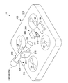
- FIG. 2 is a perspective view showing a schematic outer shape of the flying device 10.
- the flying device 10 includes a flying unit 100, a hammering inspection unit 200, and a laser range finder 300.
- the flying unit 100 includes a flying device main body 110, a fan 120, and a main body balancer 130.
- the sound hitting inspection unit 200 includes an inspection unit base 210, an arm 220, a striking unit 230, an inspection unit balancer 260, and a microphone 270.
- the inspection unit base 210 includes an inspection unit rotating shaft 211.
- the hitting unit 230 includes a distance measuring unit 240 and a force sensor 250.
- the laser range finder 300 includes a finder base 310 and a finder main body 320.
- the finder base 310 includes a finder rotation shaft 311.
- the flying unit 100 carries the striking unit 230 and flies.
- a wireless remote control type or autonomous flight type unmanned helicopter can be used as the flying unit 100.
- the fan 120 rotates to generate an air flow and operate the flying device 10. Further, the attitude of the flying device 10 is controlled by the balance of the rotational speeds of the four fans 120. By this attitude control, the flying device 10 flies in front of the one where the sound inspection unit 200 is arranged. Thereby, the hammering inspection unit 200 can be brought close to the inspection target portion 900 to perform the hammering inspection.
- the main body balancer 130 is a weight (weight) for maintaining the balance of the center of gravity of the flying device 10 with the sound hitting inspection unit 200.
- the hammering inspection unit 200 performs a hammering inspection by hitting the inspection target portion 900 from a predetermined relative position with respect to the inspection target portion 900.
- the predetermined relative position with respect to the inspection target location 900 is a position where the distance from the inspection target location 900 is a predetermined distance in front of the inspection target location 900.
- the relative position of the sound hitting inspection unit 200 with respect to the inspection target portion 900 is determined.
- the inspection unit base 210 supports the arm 220 so as to be rotatable around the axis of the inspection unit rotating shaft 211. Further, the inspection unit base 210 may support the arm 220 so as to be rotatable in the horizontal direction (the direction of the surface parallel to the upper surface of the flying device main body 110).
- the arm 220 moves the striking unit 230 by rotating around the rotation axis 211 for the inspection unit.
- the arm 220 rotates around the axis of the inspection-unit rotating shaft 211, so that the striking unit 230 is rotated. Hits the inspection target portion 900.
- the striking unit 230 moves as the arm 220 rotates as described above.
- the hitting unit 230 hits the inspection target location 900 by this movement, so that the hitting inspection unit 200 performs a hitting inspection on the inspection target location 900.
- the distance measuring unit 240 measures the distance from the hitting unit 230 to the object when there is an object in the traveling direction of the flying device 10. In particular, the distance measuring unit 240 measures the distance from the striking unit 230 to the inspection target location 900 in a state where the flying device 10 is located in front of the inspection target location 900.
- the distance measuring unit 240 measures the distance from the hitting unit 230 to the inspection target location 900 to determine whether or not the relative position of the hitting unit 230 with respect to the inspection target location 900 is an appropriate position for performing the hammering check. can do.
- a laser-type distance sensor can be used as the distance measuring unit 240, but the distance measuring unit 240 is not limited to this, and if the distance from the hitting unit 230 to an object can be measured, You may use the method of.
- an ultrasonic distance sensor may be used as the distance measuring unit 240.
- the force sensor 250 detects a force applied to the hitting unit 230. Before the hitting unit 230 hits the inspection target part 900 in the hit sound inspection, the hitting part 230 moves to a position where the inspection target part 900 is hit, and whether or not the force sensor 250 detects contact with an object. judge. Thereby, it is possible to determine whether or not the relative position of the hitting unit 230 with respect to the inspection target location 900 is an appropriate position for performing the hitting inspection.
- the inspection unit balancer 260 is a weight for maintaining the center-of-gravity balance of the hammering inspection unit 200 with the striking unit 230.
- the microphone 270 collects ambient sounds. In particular, the microphone 270 collects the hitting sound when the hitting unit 230 hits the inspection target location 900.
- the finder body 320 detects an object located in front of the flying device 10 (traveling direction), and further measures the distance from the finder body 320 to the object.
- the flying device 10 flies toward the inspection target location 900, the position of the inspection target location 900 can be detected, and the finder main body 320 can be used to confirm the presence or absence of an obstacle.
- the finder base 310 supports the finder main body 320 so as to be rotatable around the axis of the finder rotation shaft 311. Further, the finder base 310 may support the finder main body 320 so as to be rotatable in the horizontal direction (the direction of the surface parallel to the upper surface of the flying device main body 110). Alternatively, the finder base 310 may support the finder body 320 with the orientation of the finder body 320 fixed.
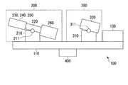
- FIG. 3 is a side view showing a schematic outer shape of the flying device 10. As shown in FIG. 3, the flying device 10 further includes a corner cube 400 in addition to the components described with reference to FIG. 2.
- the corner cube 400 reflects the light incident on the corner cube 400 itself in the incident direction.
- the corner cube 400 reflects the laser beam emitted from the ground side device 20 toward the flying device 10 to the ground side device 20.
- the ground side device 20 receives this laser beam and detects the relative position of the flying device 10 with respect to the ground side device 20.
- the corner cube 400 includes, for example, a right-angle prism or a reflection plate combined at a right angle.
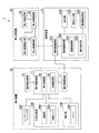
- FIG. 4 is a schematic block diagram showing the functional configuration of the inspection system 1.
- the flying device 10, the ground-side device 20, and the control device 31 are shown among the components of the inspection system 1 described with reference to FIG. 1.
- the flying unit 100, the fan 120, the sound check unit 200, the ranging unit 240, the force sensor 250, A laser range finder 300 is shown.
- the flying device 10 further includes a flight side communication unit 11, a flight side storage unit 16, and a flight side control unit 17.
- the flight side control unit 17 includes a flight processing unit 18 and an inspection processing unit 19.
- the ground side device 20 includes a ground side communication unit 21, a flying device detection unit 22, a ground side storage unit 28, and a ground side control unit 29.
- the control device 31 includes a control side communication unit 510, a display unit 520, an operation input unit 530, a control side storage unit 580, and a control side control unit 590.
- the control side control unit 590 includes a coordinate management unit 591 and a flight command unit 592.
- the flight side communication unit 11 communicates with other devices.
- the flight-side communication unit 11 receives a flight command from the control device 31.
- the flight side storage unit 16 stores various data.
- the flight side storage unit 16 is configured using a storage device provided in the flying device 10.
- the flight-side control unit 17 executes various processes by controlling each unit of the flying device 10.
- the flight-side control unit 17 is configured by, for example, a CPU (Central Processing Unit) provided in the flight device 10 reading and executing a program from the flight-side storage unit 16.
- a CPU Central Processing Unit
- the flight processing unit 18 controls the flight of the flying device 10 by controlling the rotation of the fan 120.
- the flight processing unit 18 controls the flight of the flight device 10 according to the flight command.
- the inspection processing unit 19 controls the hammering inspection unit 200 to perform a hammering inspection.
- the inspection processing unit 19 controls the hammering inspection unit 200 to rotate the arm 220 around the axis of the inspection unit rotating shaft 211 so that the hitting unit 230 strikes the inspection target portion 900.
- the inspection processing unit 19 corresponds to an example of a hitting unit position confirmation unit, and confirms the relative position of the hitting unit 230 with respect to the inspection target location 900 before the hitting unit 230 hits the inspection target location 900 for inspection. .
- the inspection processing unit 19 moves the hitting unit 230 to a position where the hitting target location 900 is hit, and determines whether or not the hitting unit 230 and the inspection target location 900 are in contact based on the sensing data of the force sensor 250. judge.
- the inspection processing unit 19 refers to the distance to the inspection target location 900 measured by the distance measuring unit 240 and determines whether or not the distance between the distance measuring unit 240 and the inspection target location 900 is a predetermined distance.
- the inspection processing unit 19 may perform only one of the above determination using the force sensor 250 and the above determination using the distance measuring unit 240, or both. Also good. However, the process which the inspection process part 19 confirms the relative position with respect to the inspection object location 900 of the hit
- the ground side communication unit 21 communicates with other devices.
- the ground side communication unit 21 transmits position information indicating the position of the flying device 10 detected by the flying device detection unit 22 to the control device 31.
- the flying device detection unit 22 detects the relative position of the flying device 10 with respect to the ground side device 20. Specifically, the flying device detection unit 22 emits a laser. When the laser reflected by the corner cube 400 of the flying device 10 is received, the flying device detection unit 22 is based on the direction in which the laser is emitted and the delay time or phase difference from when the laser is emitted until reception. Thus, the direction of the flying device 10 viewed from the ground side device 20 and the distance between the ground side device 20 and the flying device 10 are detected.
- the ground side storage unit 28 stores various data.
- the ground side storage unit 28 is configured using a storage device provided in the ground side device 20.
- the ground side control part 29 controls each part of the ground side apparatus 20, and performs various processes.
- the ground side control unit 29 controls the ground side communication unit 21 to communicate with the control device 31.
- the ground side control unit 29 controls the flying device detection unit 22 to detect the position of the flying device 10.
- the ground side control unit 29 is configured, for example, by a CPU included in the ground side device 20 reading out and executing a program from the ground side storage unit 28.
- the control side communication unit 510 communicates with other devices.
- the control-side communication unit 510 transmits a flight command to the flying device 10 according to the control of the control-side control unit 590.
- the control-side communication unit 510 transmits a flight command that instructs the forward direction of the flying device 10 to the flying device 10.
- the flight side communication unit 11 receives position information indicating the position of the flight device 10 detected by the ground side device 20 from the ground side device 20.
- the display unit 520 has a display screen such as a liquid crystal panel or an LED (Light Emitting Diode) panel, and displays various images. In particular, the display unit 520 displays the result of the hammering check. Further, the display unit 520 may display the position of the inspection target location 900 and the position of the flying device 10 according to the control of the control side control unit 590.
- a display screen such as a liquid crystal panel or an LED (Light Emitting Diode) panel
- the operation input unit 530 has input devices such as a keyboard and a mouse, for example, and receives user operations.
- the operation input unit 530 receives a user operation for designating two points on the surface of the inspection target location 900.
- coordinates are set in the inspection target location 900 in the design drawing, and the operation input unit 530 receives a user operation for inputting the coordinates of two points.
- the two points designated here are used for setting coordinates for managing the position of the flying device 10.
- the control-side storage unit 580 stores various data.
- the control-side storage unit 580 is configured using a storage device provided in the control device 31.
- the control side control unit 590 controls each unit of the control device 31 and executes various processes.
- the control side control unit 590 is configured by, for example, a CPU included in the control device 31 reading out and executing a program from the control side storage unit 580.
- the coordinate management unit 591 sets coordinates with the position of the ground side device 20 as the origin based on two points on the surface of the inspection target location 900 designated by the user operation at the operation input unit 530. Then, the coordinate management unit 591 manages the position of the flying device 10 using the set coordinates.
- the flight command unit 592 generates a flight command for the flying device 10 and transmits it to the flying device 10 via the control side communication unit 510.
- the flight command unit 592 controls the flight of the flying device 10.
- the flight command unit 592 directs the advancing direction of the flying device 10 from the ground-side device 20 toward the inspection target location 900 based on the position of the flying device 10 detected by the ground-side device 20.
- the flight command unit 592 receives designation of two points on the surface of the inspection target location 900 by a user operation. Then, the flight command unit 592 controls the flying device 10 so that the forward direction of the flying device 10 is directed in a direction orthogonal to the straight line including these two points and in a direction from the ground-side device 20 toward the inspection target location 900. .
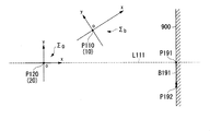
- FIG. 5 is an explanatory diagram showing an example of coordinates used in the inspection system 1.
- the example which looked at the ground side apparatus 20, the flying apparatus 10, and the inspection object location 900 from the top (the sky side) is shown.
- the flying device 10 is located at the point P110. Moreover, the ground side apparatus 20 is installed in the point P120. Points P191 and P192 indicate two points designated by the user operation.
- the coordinate management unit 591 calculates a vector connecting two points designated by the user operation. In the example of FIG. 5, the coordinate management unit 591 calculates a vector B191. Then, the coordinate management unit 591 obtains a straight line that is orthogonal to the calculated vector and that is included in the horizontal plane. In the example of FIG. 5, the coordinate management unit 591 obtains a line L111. Then, the coordinate management unit 591 sets a coordinate system ⁇ 0 with the position of the ground side device 20 as the origin based on the obtained straight line.
- the coordinate management unit 591 sets the x axis parallel to the obtained straight line with the position of the ground side device 20 as the origin. In addition, the coordinate management unit 591 sets the z axis vertically upward. Then, the coordinate management unit 591 sets a y-axis that is orthogonal to the x-axis and the z-axis. In the example of FIG. 5, an example in which the coordinate management unit 591 sets the coordinate axis of the right-handed coordinate system is shown, but the coordinate management unit 591 may set the coordinate axis of the left-handed coordinate system.
- the coordinate system ⁇ b is a coordinate system used by the flying device 10.
- the position of the flying device 10 is set as the origin.
- the x axis is set in the forward direction of the flying device 10.
- the flying device 10 flies while maintaining almost horizontal. Therefore, x-axis of the coordinate system sigma b is set along a horizontal plane.
- the z axis is set vertically upward. Then, the y axis orthogonal to the x axis and the z axis is set.
- the flying device 10 may use the coordinate axis of the left-handed coordinate system. Also moves the coordinate system sigma b with the movement of the flying device 10.
- the flying device 10 is an explanatory diagram showing an example of positions on the x-axis of the coordinate system sigma 0.
- the coordinate management unit 591 calculates a position shift of the flying device 10 with respect to the x axis of the coordinate system ⁇ 0 based on the position of the flying device 10 detected by the ground side device 20.
- the flight command unit 592 generates a flight command for moving the flying device 10 so as to be positioned on the x axis of the coordinate system ⁇ 0 based on the deviation calculated by the coordinate management unit 591, and the control side communication unit 510.
- the flying device 10 is flying according to the flight instruction is located on the x-axis of the coordinate system sigma 0.
- the forward direction of the flying device 10 as a x-axis direction of the coordinate system sigma b illustrates a direction shifted from the direction of inspection target portion 900.
- FIG. 7 is an explanatory diagram showing an example in which the flying device 10 is located on the x-axis of the coordinate system ⁇ 0 and the forward direction of the flying device 10 matches the x direction of the coordinate system ⁇ 0 .
- the flight command unit 592 instructs the flight device 10 to go straight by a flight instruction.
- the coordinate management unit 591 can detect the forward direction of the flying device 10.
- the coordinate management unit 591 can detect a coordinate system sigma b.
- Flight instruction unit 592 based on the deviation between the forward direction and the x direction of the coordinate system sigma 0 of the flying device 10 which coordinates management unit 591 detects, the flight instruction for suited the flying device 10 in a direction to reduce the deviation It is generated and transmitted to the flying device 10 via the control side communication unit 510.
- the flying device 10 flies in accordance with this flight command, the deviation between the forward direction of the flying device 10 and the x direction of the coordinate system ⁇ 0 is reduced, and eventually the forward direction of the flying device 10 is changed as in the example of FIG. matching in the x direction of the coordinate system sigma 0. If the flying device 10 travels straight from this state, it can reach the inspection target location 900. And the advancing direction of the flying device 10 is orthogonal to the surface of the inspection object location 900. As a result, the hammering inspection unit 200 can perform a hammering inspection with an appropriate positional relationship with respect to the inspection target location 900.
- control device 31 is a flowchart showing an example of a processing procedure for setting a coordinate system sigma 0.
- the coordinate management unit 591 acquires the coordinates of two points designated by the user operation (step S101).
- the coordinate management unit 591 calculates a direction orthogonal to the vector connecting the two points (step S102).
- the coordinate management unit 591 acquires the position coordinates of the ground side device 20 (step S103).
- the ground-side device 20 measures the position of the ground-side device 20 itself, and notifies the coordinate management unit 591 of the positioning result in latitude and longitude.
- the coordinate management unit 591 sets the coordinate system ⁇ 0 based on the direction obtained in step S102 and the positional relationship between the position obtained in step S103 and the inspection target location 900 (step S104).
- step S104 the process in FIG.
- FIG. 9 is an explanatory diagram showing an example of processing in which the control device 31 controls the position and orientation of the flying device 10.
- the ground-side device 20 detects the position of the flying device 10 (sequence S201). And the ground side apparatus 20 notifies the detected position to the control apparatus 31 (sequence S202).
- the control device 31 instructs the flying device 10 to fly straight (sequence S211). According to this instruction, the flying device 10 flies straight (sequence S212). That is, the flying device 10 flies in the forward direction.
- the ground side device 20 detects the position of the flying device 10 (sequence S213).
- the ground side apparatus 20 notifies the detected position to the control apparatus 31 (sequence S214).
- the control device 31 calculates the straight traveling direction (forward direction) of the flying device 10 based on the position obtained in sequence S202 and the position obtained in sequence S214 (sequence S221).
- control device 31 calculates a flight path for making the forward direction of the flying device 10 coincide with the x direction of the coordinate system ⁇ 0 (sequence S222).
- the control device 31 determines the flight direction instructed to the flight device 10 based on the determined flight path (sequence S223).
- control device 31 instructs flying device 10 of the determined flight direction (sequence S224).
- the flying device 10 flies according to the instruction (sequence S225).
- the ground side device 20 detects the position of the flying device 10 (sequence S231).
- the ground side apparatus 20 notifies the detected position to the control apparatus 31 (sequence S232).
- the control device 31 detects the forward direction of the flying device 10 and determines whether or not it matches the x direction of the coordinate system ⁇ 0 (sequence S233).
- sequence S233 YES
- sequence S233: NO the processing returns to the sequence S221.
- FIG. 10 is a flowchart showing an example of a processing procedure in which the flying device 10 performs a hammering test.
- the inspection processing unit 19 determines whether or not the flying device 10 is located in front of the inspection target location 900 (step S301).
- step S301 NO
- the flight processing unit 18 adjusts the position of the flying device 10 (step S302). After step S302, the process returns to step S301.
- step S301 when it determines with it being located in the front (step S301: YES), the inspection process part 19 determines whether the distance of the flying apparatus 10 and the inspection object location 900 is appropriate (step S311).
- step S311 NO
- the flight processing unit 18 adjusts the position of the flying device 10 (step S312). After step S312, the process returns to step S311.
- step S311 determines whether the orientation of the flying device 10 is appropriate (step S321).
- step S321 NO
- the flight processing unit 18 adjusts the orientation of the flying device 10 (step S322). After step S322, the process returns to step S321.
- step S321 when it is determined that the orientation is appropriate (step S321: YES), the inspection processing unit 19 performs a process of confirming the hitting position as described above (step S331).
- the inspection processing unit 19 determines whether or not the hitting unit 230 hits the inspection target location 900 (step S332). If it is determined that it is a hit (step S332: YES), the inspection processing unit 19 performs a hammering inspection (step S341). And the inspection process part 19 transmits a result to the control apparatus 31 via the flight side communication part 11 (step S342).
- step S342 the process of FIG.
- step S351 when it determines with the hit
- step S351 the process of FIG.
- the flying device 10 may use a plurality of coordinates according to the degree of freedom of the flying unit 100. This point will be described with reference to FIGS. 11 and 12.
- FIG. 11 is a perspective view showing an outline of the outline of a flying device provided with a sounding inspection unit with a higher degree of freedom.
- the flying device 600 shown in FIG. 11 is different in the structure of the sound hitting inspection unit 601 from that of the flying unit 100 (FIG. 2) of the flying device 10. Other than that is the same as that of the flying device 10.
- the hitting sound check unit 601 includes an arm 620, a hitting unit 630, and a joint unit 660 instead of the arm 220, the hitting unit 230, and the checking unit balancer 260.
- the distance measuring unit 240 and the force sensor 250 are built in the hitting unit 630.
- the joint part 660 connects the arm 620 and the striking part 630 with a variable angle. Thereby, in the sound inspection part 601, the degree of freedom of movement of the striking part 630 is higher than that of the striking part 230 of the flying part 100.
- FIG. 12 is an explanatory diagram showing an example of a coordinate system used by the flying device 600.
- the flying device 600 uses coordinate systems ⁇ b , ⁇ pb , and ⁇ pt .
- Coordinate system sigma b of FIG. 12 is the same as the coordinate system sigma b of FIGS. 5-7.
- the coordinate system sigma b of FIG. 12 the origin is set to the center of gravity (point P210) of the flying device 600.
- the x axis is set in the forward direction of the flying device 600.
- the z axis is set vertically upward, and the y axis is set orthogonal to the x axis and the z axis.
- the flying device 600 uses a right-handed coordinate system coordinate axis, but the flying device 600 may use the left-handed coordinate system coordinate axis.
- the origin is set at the connection portion (point P220) between the sound hitting inspection unit 601 and the flying device main body 110.
- the x-axis is set in the direction in which the longitudinal direction of the arm 620 is projected onto the horizontal plane.
- the z axis is set vertically upward, and the y axis is set orthogonal to the x axis and the z axis.
- Flying device 600 also coordinates sigma pb is, an example of a case of using coordinate axes of right-handed coordinate system, the flying device 600 may be used axes of left-handed.
- the origin is set at the tip (point P230) of the striking portion 630. This tip is a portion in contact with the inspection object location 900.
- the x-axis is set in the longitudinal direction of the arm 620
- the y-axis is set in the horizontal plane at right angles to the x-axis.
- the z axis is set in a direction orthogonal to the x axis and the y axis.
- flying device 600 may be used to coordinate axes of right-handed coordinate system, may be used axes of left-handed.
- the flight processing unit 18 and the inspection processing unit 19 use different coordinate systems depending on the object of operation. Further, the relationship between the coordinates can be detected by the operation of the servo motor or the sensor, and the flight processing unit 18 and the inspection processing unit 19 perform coordinate conversion as necessary.
- the hitting inspection units 200 and 601 perform the inspection by hitting the inspection target portion 900 from a predetermined relative position with respect to the inspection target portion 900.
- the flying unit 100 flies with the hitting sound checking units 200 and 601.
- the ground side device 20 is fixedly installed with respect to the inspection target location 900 and detects the positions of the flying devices 10 and 600.
- the flight command unit 592 directs the forward direction of the flying devices 10 and 600 toward the inspection target location 900 from the ground side device 20 based on the positions of the flying devices 10 and 600 detected by the ground side device 20.
- the flying devices 10 and 600 are controlled.
- the flight command unit 592 performs a process of directing the forward direction of the flying devices 10 and 600 toward the inspection target location 900, so that the work inspector does not need to operate the flying devices 10 and 600, and the hammering check is performed. It can be carried out.
- the flying devices 10 and 600 are used as devices for moving the hammering inspection units 200 and 601, the hammering inspection can be performed even in places where it is difficult for the vehicle to enter.
- the hitting units 230 and 630 hit the inspection target portion 900.
- the inspection process part 19 confirms the relative position with respect to the inspection object location 900 of the hit
- the inspection system 1 it is possible to reduce the possibility that the inspection target location 900 is hit from an inappropriate position and the accuracy of the hitting inspection is lowered.
- the force sensor 250 detects the force applied to the hitting units 230 and 630.
- the inspection processing unit 19 moves the hitting units 230 and 630 to a position where the hitting point 900 is hit, and determines whether or not the hitting units 230 and 630 and the checkable point 900 are in contact based on the sensing data of the force sensor 250. To do.
- the inspection system 1 it is possible to confirm whether or not the hammering inspection can be properly performed by a simple process of determining whether or not the pressure sensor 250 detects pressure.
- the distance measuring unit 240 measures the distance between the hitting units 230 and 630 and the inspection target location 900. Then, the inspection processing unit 19 determines whether or not the distance between the hitting units 230 and 630 and the inspection target location 900 is a predetermined distance.
- the inspection system 1 it is possible to confirm whether or not the hammering inspection can be appropriately performed by a simple process of determining whether or not the distance detected by the distance measuring unit 240 is a predetermined distance.
- the flight command unit 592 receives the designation of two points on the surface of the inspection target location 900, and checks the forward direction of the flying devices 10 and 600 from the direction perpendicular to the straight line including the two points and from the ground side device 20.
- the flying devices 10 and 600 are controlled so as to be directed toward the target location 900.
- the inspection operator only needs to perform a simple process of designating two points on the surface of the inspection target location 900, and does not need to operate the flying devices 10 and 600. In this respect, the burden on the inspection worker can be reduced.
- FIG. 13 is an explanatory diagram showing the minimum configuration of the inspection system according to the present invention.
- the inspection system 50 shown in the figure includes a flying device 51, a ground side device 54, and a flight command unit 55.
- the flying device 51 includes a sound hitting inspection unit 52 and a flying unit 53.
- the sound inspection unit 52 performs an inspection by hitting the inspection target portion from a predetermined relative position with respect to the inspection target portion.
- the flying unit 53 carries the sound check unit 52 and flies.
- the ground-side device 54 is installed with a fixed relative position with respect to the inspection target location, and detects the position of the flying device 51. Then, based on the position of the flying device 51 detected by the ground side device 54, the flight command unit 55 directs the flying device 51 so that the forward direction of the flying device 51 is directed from the ground side device 54 toward the inspection target location. Control.
- the flight command unit 55 performs the process of directing the forward direction of the flying device 51 to the inspection target location, it is possible to perform a hammering check without having to operate the flying device 51 by the work inspector.
- the flying device 51 is used as a device for moving the hammering inspection unit 52, the hammering inspection can be performed even in a place where it is difficult for the vehicle to enter.
- FIG. 14 is an explanatory view showing the minimum configuration of the control device according to the present invention.
- the control device 60 shown in the figure includes a flight command unit 61.
- the flight command unit 61 includes a hammering inspection unit that performs inspection by hitting the inspection target portion from a predetermined relative position with respect to the inspection target portion, and a flying unit that carries the hammering inspection unit and flies.
- a flying unit that carries the hammering inspection unit and flies.
- the flight command unit 61 performs the process of directing the forward direction of the flying device to the inspection target location, the hammering check can be performed without the need for the operation inspector to operate the flying device.
- the flying device is used as a device for moving the hammering inspection unit, the hammering inspection can be performed even in places where it is difficult for the vehicle to enter.
- a program for realizing all or part of the functions of the flight side control unit 17, the ground side control unit 29, and the control side control unit 590 is recorded on a computer-readable recording medium. Each unit may be processed by causing the computer system to read and execute the program recorded on the computer.
- the “computer system” includes hardware such as an OS (Operating System) and peripheral devices.
- Computer-readable recording medium means a flexible disk, a magneto-optical disk, a portable medium such as a ROM (Read Only Memory), a CD-ROM (Compact Disc Only Memory), or a hard disk built in a computer system.
- the program may be a program for realizing a part of the functions described above, and may be a program capable of realizing the functions described above in combination with a program already recorded in a computer system.
Landscapes
- Physics & Mathematics (AREA)
- Engineering & Computer Science (AREA)
- General Physics & Mathematics (AREA)
- Aviation & Aerospace Engineering (AREA)
- Life Sciences & Earth Sciences (AREA)
- General Health & Medical Sciences (AREA)
- Health & Medical Sciences (AREA)
- Analytical Chemistry (AREA)
- Chemical & Material Sciences (AREA)
- Immunology (AREA)
- Pathology (AREA)
- Biochemistry (AREA)
- Acoustics & Sound (AREA)
- Radar, Positioning & Navigation (AREA)
- Remote Sensing (AREA)
- Automation & Control Theory (AREA)
- Structural Engineering (AREA)
- Civil Engineering (AREA)
- Architecture (AREA)
- Optics & Photonics (AREA)
- Electromagnetism (AREA)
- Mining & Mineral Resources (AREA)
- General Life Sciences & Earth Sciences (AREA)
- Geochemistry & Mineralogy (AREA)
- Geology (AREA)
- Investigating Or Analyzing Materials By The Use Of Ultrasonic Waves (AREA)
- Control Of Position, Course, Altitude, Or Attitude Of Moving Bodies (AREA)
- Underground Structures, Protecting, Testing And Restoring Foundations (AREA)
- Bridges Or Land Bridges (AREA)
Abstract
Description
10、51、600 飛行装置
11 飛行側通信部
16 飛行側記憶部
17 飛行側制御部
18 飛行処理部
19 点検処理部
20、54 地上側装置
21 地上側通信部
22 飛行装置検出部
28 地上側記憶部
29 地上側制御部
30 管制システム
31、60 管制装置
32 電源装置
52、200、601 打音点検部
53、100 飛行部
55、61、592 飛行指令部
110 飛行装置本体
120 ファン
130 本体用バランサ
210 点検部用台座
211 点検部用回転軸
220、620 アーム
230、630 打撃部
240 測距部
250 力覚センサ
260 点検部用バランサ
270 マイク
300 レーザレンジファインダ
310 ファインダ用台座
311 ファインダ用回転軸
320 ファインダ本体
400 コーナーキューブ
510 管制側通信部
520 表示部
530 操作入力部
580 管制側記憶部
590 管制側制御部
591 座標管理部
660 ジョイント部
900 点検対象箇所
Claims (8)
- 点検対象箇所に対して所定の相対位置から前記点検対象箇所を叩いて点検を行う打音点検手段と、
前記打音点検手段を搭載して飛行する飛行手段と、
を備える飛行装置と、
前記点検対象箇所に対する相対位置を固定に設置されて前記飛行装置の位置を検出する地上側装置と、
前記地上側装置が検出した前記飛行装置の位置に基づいて、前記飛行装置の前進方向を、前記地上側装置から前記点検対象箇所へ向かう方向に向けるよう前記飛行装置を制御する飛行指令手段と、
を備える点検システム。 - 前記打音点検手段は、前記点検対象箇所を叩く打撃手段を備え、
前記飛行装置は、前記打撃手段が検査のために前記点検対象箇所を叩く前に、前記打撃手段の前記点検対象箇所に対する相対位置を確認する打撃手段位置確認手段を備える、
請求項1に記載の点検システム。 - 前記打撃手段に加わる力を検出する力覚センサを備え、
前記打撃手段位置確認手段は、前記打撃手段を前記点検対象箇所を叩く位置へ移動させ、前記力覚センサのセンシングデータに基づいて前記打撃手段と前記点検対象箇所との接触の有無を判定する、
請求項2に記載の点検システム。 - 前記打撃手段と前記点検対象箇所との距離を測定する測距手段を備え、
前記打撃手段位置確認手段は、前記打撃手段と前記点検対象箇所との距離が所定の距離か否かを判定する、
請求項2または請求項3に記載の点検システム。 - 前記飛行指令手段は、前記点検対象箇所の表面における2点の指定を受け、前記飛行装置の前進方向を、前記2点を含む直線と直交する方向、かつ、前記地上側装置から前記点検対象箇所へ向かう方向に向けるよう前記飛行装置を制御する、請求項1から4のいずれか一項に記載の点検システム。
- 点検対象箇所に対して所定の相対位置から前記点検対象箇所を叩いて点検を行う打音点検手段と、前記打音点検手段を搭載して飛行する飛行手段とを備える飛行装置の前進方向を、前記点検対象箇所に対する相対位置を固定に設置されて前記飛行装置の位置を検出する地上側装置から前記点検対象箇所へ向かう方向に向けるよう、前記地上側装置が検出する前記飛行装置の位置に基づいて前記飛行装置を制御する飛行指令手段を備える管制装置。
- 点検対象箇所に対して所定の相対位置から前記点検対象箇所を叩いて点検を行う打音点検手段と、前記打音点検手段を搭載して飛行する飛行手段とを備える飛行装置の前進方向を、前記点検対象箇所に対する相対位置を固定に設置されて前記飛行装置の位置を検出する地上側装置から前記点検対象箇所へ向かう方向に向けるよう、前記地上側装置が検出する前記飛行装置の位置に基づいて前記飛行装置を制御する管制方法。
- コンピュータに、
点検対象箇所に対して所定の相対位置から前記点検対象箇所を叩いて点検を行う打音点検手段と、前記打音点検手段を搭載して飛行する飛行手段とを備える飛行装置の前進方向を、前記点検対象箇所に対する相対位置を固定に設置されて前記飛行装置の位置を検出する地上側装置から前記点検対象箇所へ向かう方向に向けるよう、前記地上側装置が検出する前記飛行装置の位置に基づいて前記飛行装置を制御する処理を実行させるプログラムを格納する、コンピュータが読み取り可能な記録媒体。
Priority Applications (6)
| Application Number | Priority Date | Filing Date | Title |
|---|---|---|---|
| CN201780031275.3A CN109154584A (zh) | 2016-05-27 | 2017-05-17 | 检查系统、控制设备、控制方法和记录介质 |
| EP17802642.3A EP3467492B1 (en) | 2016-05-27 | 2017-05-17 | Inspection system, control device, control method, and recording medium |
| JP2018519212A JP6891884B2 (ja) | 2016-05-27 | 2017-05-17 | 点検システム、管制装置、管制方法、及び、プログラム |
| KR1020187034357A KR20190002600A (ko) | 2016-05-27 | 2017-05-17 | 점검 시스템, 관제 장치, 관제 방법 및 기록 매체 |
| US16/303,290 US11105775B2 (en) | 2016-05-27 | 2017-05-17 | Inspection system, control device, and control method |
| CA3022518A CA3022518C (en) | 2016-05-27 | 2017-05-17 | Inspection system, control device, control method and recording medium |
Applications Claiming Priority (2)
| Application Number | Priority Date | Filing Date | Title |
|---|---|---|---|
| JP2016106764 | 2016-05-27 | ||
| JP2016-106764 | 2016-05-27 |
Publications (1)
| Publication Number | Publication Date |
|---|---|
| WO2017204050A1 true WO2017204050A1 (ja) | 2017-11-30 |
Family
ID=60412249
Family Applications (1)
| Application Number | Title | Priority Date | Filing Date |
|---|---|---|---|
| PCT/JP2017/018508 WO2017204050A1 (ja) | 2016-05-27 | 2017-05-17 | 点検システム、管制装置、管制方法、及び、記録媒体 |
Country Status (8)
| Country | Link |
|---|---|
| US (1) | US11105775B2 (ja) |
| EP (1) | EP3467492B1 (ja) |
| JP (1) | JP6891884B2 (ja) |
| KR (1) | KR20190002600A (ja) |
| CN (1) | CN109154584A (ja) |
| CA (1) | CA3022518C (ja) |
| TW (1) | TWI682876B (ja) |
| WO (1) | WO2017204050A1 (ja) |
Cited By (5)
| Publication number | Priority date | Publication date | Assignee | Title |
|---|---|---|---|---|
| JP2019189186A (ja) * | 2018-04-27 | 2019-10-31 | 富士通株式会社 | 飛翔機及び飛翔機の制御方法 |
| WO2019211800A1 (en) * | 2018-05-03 | 2019-11-07 | Uvic Industry Partnerships Inc. | Uav-based acoustic technique for mapping defects in civil infrastructure |
| JP2019196973A (ja) * | 2018-05-09 | 2019-11-14 | 学校法人桐蔭学園 | 非接触音響解析システム及び非接触音響解析方法 |
| US20200355608A1 (en) * | 2019-05-09 | 2020-11-12 | Advantest Corporation | Optical testing apparatus |
| JPWO2020040105A1 (ja) * | 2018-08-22 | 2021-08-10 | 日本電気株式会社 | 選定装置、選定方法及び選定プログラム |
Families Citing this family (6)
| Publication number | Priority date | Publication date | Assignee | Title |
|---|---|---|---|---|
| WO2018179404A1 (ja) * | 2017-03-31 | 2018-10-04 | 日本電気株式会社 | 情報処理装置、情報処理方法、および情報処理プログラム |
| KR101997674B1 (ko) * | 2019-01-14 | 2019-07-09 | 라온구조안전기술(주) | 연직상향 타격 가능 구조를 가지는 드론 방식의 비파괴 콘크리트 강도 측정장치 및 측정방법 |
| KR102247466B1 (ko) * | 2019-09-09 | 2021-05-03 | 주식회사 노아 | 비파괴 타음 검사장치와 비파괴 타음 검사방법 |
| CN111846280B (zh) * | 2020-07-24 | 2022-11-01 | 中国航空工业集团公司西安飞行自动控制研究所 | 一种飞控系统stp参数调节方法 |
| CN112878180A (zh) * | 2021-04-09 | 2021-06-01 | 王国爱 | 一种基于无人机桥梁桩基成孔检测装置 |
| JP2023050515A (ja) * | 2021-09-30 | 2023-04-11 | 株式会社トプコン | 打音検査システム |
Citations (8)
| Publication number | Priority date | Publication date | Assignee | Title |
|---|---|---|---|---|
| JPS595492B2 (ja) | 1973-12-11 | 1984-02-04 | ゼロツクス コ−ポレ−シヨン | 紙葉給送装置 |
| JP2004205216A (ja) | 2002-12-20 | 2004-07-22 | Hazama Corp | トンネル覆工コンクリートの打音検査装置 |
| JP2004301665A (ja) | 2003-03-31 | 2004-10-28 | Toshiba Plant Systems & Services Corp | 壁面検査ロボットシステム及び壁面検査方法 |
| JP2005091298A (ja) * | 2003-09-19 | 2005-04-07 | Komatsu Engineering Corp | 画像処理を用いたグローバル座標取得装置 |
| JP2012145346A (ja) | 2011-01-07 | 2012-08-02 | Eda Tokushu Bosui Kogyo Kk | 外壁浮き検知システム、外壁浮き検知方法並びに外壁浮き検知用移動飛行体 |
| US20120262708A1 (en) * | 2009-11-25 | 2012-10-18 | Cyberhawk Innovations Limited | Unmanned aerial vehicle |
| JP2015169435A (ja) * | 2014-03-04 | 2015-09-28 | 中国電力株式会社 | コンクリート構造物の健全性検査装置、健全性検査用ハンマ及び健全性検査方法 |
| JP2016106764A (ja) | 2014-12-04 | 2016-06-20 | 富士フイルム株式会社 | 内視鏡の撮像光学系及び撮像ユニット並びに内視鏡 |
Family Cites Families (11)
| Publication number | Priority date | Publication date | Assignee | Title |
|---|---|---|---|---|
| US4799375A (en) * | 1983-10-26 | 1989-01-24 | Pcb Piezotronics, Inc. | Instrumented test hammer |
| FR2807603B1 (fr) * | 2000-04-05 | 2002-10-11 | Freyssinet Int Stup | Procede et systeme pour effectuer des releves de caracteristiques visibles sur des parois |
| JP3595492B2 (ja) | 2000-06-09 | 2004-12-02 | 三菱重工業株式会社 | 構造物打音検査装置およびトンネル用打音検査装置 |
| US7643893B2 (en) * | 2006-07-24 | 2010-01-05 | The Boeing Company | Closed-loop feedback control using motion capture systems |
| JP5109803B2 (ja) * | 2007-06-06 | 2012-12-26 | ソニー株式会社 | 画像処理装置、画像処理方法及び画像処理プログラム |
| BRPI0910573B1 (pt) * | 2008-04-17 | 2019-09-03 | The Travelers Indemnity Company | sistema para processamento de uma reivindicação de seguro de propriedade |
| EP2511781A1 (de) | 2011-04-14 | 2012-10-17 | Hexagon Technology Center GmbH | System und Verfahren zur Steuerung eines unbemannten Fluggeräts |
| US8738226B2 (en) | 2011-07-18 | 2014-05-27 | The Boeing Company | Holonomic motion vehicle for travel on non-level surfaces |
| FR2999715B1 (fr) | 2012-12-18 | 2015-01-16 | Airbus Operations Sas | Dispositif et procede de detection d'un impact sur une structure en materiau composite. |
| JP5882951B2 (ja) | 2013-06-14 | 2016-03-09 | 株式会社トプコン | 飛行体誘導システム及び飛行体誘導方法 |
| JP6648971B2 (ja) * | 2014-03-27 | 2020-02-19 | 株式会社フジタ | 構造物の点検装置 |
-
2017
- 2017-04-26 TW TW106113894A patent/TWI682876B/zh active
- 2017-05-17 CN CN201780031275.3A patent/CN109154584A/zh active Pending
- 2017-05-17 KR KR1020187034357A patent/KR20190002600A/ko not_active IP Right Cessation
- 2017-05-17 WO PCT/JP2017/018508 patent/WO2017204050A1/ja unknown
- 2017-05-17 EP EP17802642.3A patent/EP3467492B1/en active Active
- 2017-05-17 US US16/303,290 patent/US11105775B2/en active Active
- 2017-05-17 JP JP2018519212A patent/JP6891884B2/ja active Active
- 2017-05-17 CA CA3022518A patent/CA3022518C/en active Active
Patent Citations (8)
| Publication number | Priority date | Publication date | Assignee | Title |
|---|---|---|---|---|
| JPS595492B2 (ja) | 1973-12-11 | 1984-02-04 | ゼロツクス コ−ポレ−シヨン | 紙葉給送装置 |
| JP2004205216A (ja) | 2002-12-20 | 2004-07-22 | Hazama Corp | トンネル覆工コンクリートの打音検査装置 |
| JP2004301665A (ja) | 2003-03-31 | 2004-10-28 | Toshiba Plant Systems & Services Corp | 壁面検査ロボットシステム及び壁面検査方法 |
| JP2005091298A (ja) * | 2003-09-19 | 2005-04-07 | Komatsu Engineering Corp | 画像処理を用いたグローバル座標取得装置 |
| US20120262708A1 (en) * | 2009-11-25 | 2012-10-18 | Cyberhawk Innovations Limited | Unmanned aerial vehicle |
| JP2012145346A (ja) | 2011-01-07 | 2012-08-02 | Eda Tokushu Bosui Kogyo Kk | 外壁浮き検知システム、外壁浮き検知方法並びに外壁浮き検知用移動飛行体 |
| JP2015169435A (ja) * | 2014-03-04 | 2015-09-28 | 中国電力株式会社 | コンクリート構造物の健全性検査装置、健全性検査用ハンマ及び健全性検査方法 |
| JP2016106764A (ja) | 2014-12-04 | 2016-06-20 | 富士フイルム株式会社 | 内視鏡の撮像光学系及び撮像ユニット並びに内視鏡 |
Non-Patent Citations (3)
| Title |
|---|
| KOKI HOSOYAMA ET AL.: "UAV no Jiritsu Hiko no Kaihatsu", JAPAN SOCIETY OF PHOTOGRAMMETY AND REMOTE SENSING HEISEI 28 NENDO GAKUJUTSU KOENKAI HAPPYO RONBUNSHU, 26 May 2016 (2016-05-26), pages 51 - 52 * |
| See also references of EP3467492A4 |
| TOSHIHIRO NISHIZAWA: "Kyoryo·Tunnel Tenken'yo Daon Kensa Hiko Robot System no Kenkyu Kaihatsu", KENKYU KAIHATSU SHOKOMOKU (4) TO (B) IJI KANRI ROBOT·SAIGAI TAIO ROBOT NO KAIHATSU, 5 November 2014 (2014-11-05), pages 1 - 10 * |
Cited By (10)
| Publication number | Priority date | Publication date | Assignee | Title |
|---|---|---|---|---|
| JP2019189186A (ja) * | 2018-04-27 | 2019-10-31 | 富士通株式会社 | 飛翔機及び飛翔機の制御方法 |
| JP7020279B2 (ja) | 2018-04-27 | 2022-02-16 | 富士通株式会社 | 飛翔機及び飛翔機の制御方法 |
| WO2019211800A1 (en) * | 2018-05-03 | 2019-11-07 | Uvic Industry Partnerships Inc. | Uav-based acoustic technique for mapping defects in civil infrastructure |
| US11774407B2 (en) | 2018-05-03 | 2023-10-03 | Uvic Industry Partnerships Inc. | UAV-based acoustic technique for mapping defects in civil infrastructure |
| JP2019196973A (ja) * | 2018-05-09 | 2019-11-14 | 学校法人桐蔭学園 | 非接触音響解析システム及び非接触音響解析方法 |
| JP7117729B2 (ja) | 2018-05-09 | 2022-08-15 | 学校法人桐蔭学園 | 非接触音響解析システム及び非接触音響解析方法 |
| JPWO2020040105A1 (ja) * | 2018-08-22 | 2021-08-10 | 日本電気株式会社 | 選定装置、選定方法及び選定プログラム |
| JP7036220B2 (ja) | 2018-08-22 | 2022-03-15 | 日本電気株式会社 | 選定装置、選定方法及び選定プログラム |
| US20200355608A1 (en) * | 2019-05-09 | 2020-11-12 | Advantest Corporation | Optical testing apparatus |
| US11635374B2 (en) * | 2019-05-09 | 2023-04-25 | Advantest Corporation | Optical testing apparatus |
Also Published As
| Publication number | Publication date |
|---|---|
| CA3022518C (en) | 2021-07-20 |
| EP3467492B1 (en) | 2021-08-25 |
| CA3022518A1 (en) | 2017-11-30 |
| JP6891884B2 (ja) | 2021-06-18 |
| KR20190002600A (ko) | 2019-01-08 |
| JPWO2017204050A1 (ja) | 2019-04-04 |
| TWI682876B (zh) | 2020-01-21 |
| EP3467492A4 (en) | 2019-04-10 |
| CN109154584A (zh) | 2019-01-04 |
| TW201806825A (zh) | 2018-03-01 |
| EP3467492A1 (en) | 2019-04-10 |
| US11105775B2 (en) | 2021-08-31 |
| US20190212304A1 (en) | 2019-07-11 |
Similar Documents
| Publication | Publication Date | Title |
|---|---|---|
| JP6891884B2 (ja) | 点検システム、管制装置、管制方法、及び、プログラム | |
| JP5882951B2 (ja) | 飛行体誘導システム及び飛行体誘導方法 | |
| US20200378927A1 (en) | Inspection system, mobile robot device, and inspection method | |
| KR101606447B1 (ko) | 물체 표면의 3d 좌표들을 결정하기 위한 측정 시스템 | |
| ES2527268T3 (es) | Robot multifunción para desplazarse sobre una pared utilizando un sistema de posicionamiento global de interior | |
| JP2017144784A (ja) | 飛行計画作成方法及び飛行体誘導システム | |
| JP6051751B2 (ja) | 金属板の位置および姿勢検出方法および装置、ならびに金属板の検査方法 | |
| JP2018128278A (ja) | 打音検査装置及び打撃検査システム | |
| US11919176B2 (en) | Mobile construction robot | |
| WO2020171090A1 (ja) | 金属板用自走式検査装置及び検査方法、並びに金属板の製造方法 | |
| JP2014089173A (ja) | 金属板用自走式検査装置および検査方法 | |
| JP6691878B2 (ja) | 弾性波計測システム | |
| JP6946509B2 (ja) | 飛行計画作成方法及び飛行体誘導システム | |
| EP1930240B1 (en) | Method and system for navigating a nondestructive evaluation device | |
| KR101283932B1 (ko) | 짐벌 플랫폼의 지향 오차 측정 방법 및 그 장치 | |
| JP2023140509A (ja) | 測量システム | |
| JP2009014436A (ja) | 球形タンクの溶接検査システム | |
| JP2022074712A (ja) | トンネル内空情報取得方法 | |
| JP2011038799A (ja) | 位置検出装置、位置検出方法およびプログラム | |
| JP6973425B2 (ja) | 金属板用自走式検査装置及び検査方法 | |
| JP7024746B2 (ja) | 金属板用自走式検査装置および金属板用自走式検査方法、ならびに検査システム | |
| JPH06247393A (ja) | 飛行船の障害物自動回避装置付自動操船装置 | |
| JPH1194549A (ja) | 自動追尾式測量装置 | |
| JP7170463B2 (ja) | 測量用移動装置 | |
| JPH0474649B2 (ja) |
Legal Events
| Date | Code | Title | Description |
|---|---|---|---|
| ENP | Entry into the national phase |
Ref document number: 2018519212 Country of ref document: JP Kind code of ref document: A |
|
| ENP | Entry into the national phase |
Ref document number: 3022518 Country of ref document: CA |
|
| ENP | Entry into the national phase |
Ref document number: 20187034357 Country of ref document: KR Kind code of ref document: A |
|
| 121 | Ep: the epo has been informed by wipo that ep was designated in this application |
Ref document number: 17802642 Country of ref document: EP Kind code of ref document: A1 |
|
| NENP | Non-entry into the national phase |
Ref country code: DE |
|
| ENP | Entry into the national phase |
Ref document number: 2017802642 Country of ref document: EP Effective date: 20190102 |