WO2017168842A1 - 通信用電線 - Google Patents
通信用電線 Download PDFInfo
- Publication number
- WO2017168842A1 WO2017168842A1 PCT/JP2016/085960 JP2016085960W WO2017168842A1 WO 2017168842 A1 WO2017168842 A1 WO 2017168842A1 JP 2016085960 W JP2016085960 W JP 2016085960W WO 2017168842 A1 WO2017168842 A1 WO 2017168842A1
- Authority
- WO
- WIPO (PCT)
- Prior art keywords
- wire
- sheath
- communication
- conductor
- insulated
- Prior art date
- Legal status (The legal status is an assumption and is not a legal conclusion. Google has not performed a legal analysis and makes no representation as to the accuracy of the status listed.)
- Ceased
Links
Images
Classifications
-
- H—ELECTRICITY
- H01—ELECTRIC ELEMENTS
- H01B—CABLES; CONDUCTORS; INSULATORS; SELECTION OF MATERIALS FOR THEIR CONDUCTIVE, INSULATING OR DIELECTRIC PROPERTIES
- H01B7/00—Insulated conductors or cables characterised by their form
- H01B7/02—Disposition of insulation
- H01B7/0208—Cables with several layers of insulating material
- H01B7/0216—Two layers
-
- H—ELECTRICITY
- H01—ELECTRIC ELEMENTS
- H01B—CABLES; CONDUCTORS; INSULATORS; SELECTION OF MATERIALS FOR THEIR CONDUCTIVE, INSULATING OR DIELECTRIC PROPERTIES
- H01B11/00—Communication cables or conductors
- H01B11/02—Cables with twisted pairs or quads
-
- H—ELECTRICITY
- H01—ELECTRIC ELEMENTS
- H01B—CABLES; CONDUCTORS; INSULATORS; SELECTION OF MATERIALS FOR THEIR CONDUCTIVE, INSULATING OR DIELECTRIC PROPERTIES
- H01B11/00—Communication cables or conductors
- H01B11/02—Cables with twisted pairs or quads
- H01B11/06—Cables with twisted pairs or quads with means for reducing effects of electromagnetic or electrostatic disturbances, e.g. screens
- H01B11/08—Screens specially adapted for reducing cross-talk
-
- H—ELECTRICITY
- H01—ELECTRIC ELEMENTS
- H01B—CABLES; CONDUCTORS; INSULATORS; SELECTION OF MATERIALS FOR THEIR CONDUCTIVE, INSULATING OR DIELECTRIC PROPERTIES
- H01B11/00—Communication cables or conductors
- H01B11/02—Cables with twisted pairs or quads
- H01B11/06—Cables with twisted pairs or quads with means for reducing effects of electromagnetic or electrostatic disturbances, e.g. screens
- H01B11/10—Screens specially adapted for reducing interference from external sources
-
- H—ELECTRICITY
- H01—ELECTRIC ELEMENTS
- H01B—CABLES; CONDUCTORS; INSULATORS; SELECTION OF MATERIALS FOR THEIR CONDUCTIVE, INSULATING OR DIELECTRIC PROPERTIES
- H01B11/00—Communication cables or conductors
- H01B11/02—Cables with twisted pairs or quads
- H01B11/12—Arrangements for exhibiting specific transmission characteristics
-
- H—ELECTRICITY
- H01—ELECTRIC ELEMENTS
- H01B—CABLES; CONDUCTORS; INSULATORS; SELECTION OF MATERIALS FOR THEIR CONDUCTIVE, INSULATING OR DIELECTRIC PROPERTIES
- H01B13/00—Apparatus or processes specially adapted for manufacturing conductors or cables
- H01B13/02—Stranding-up
-
- H—ELECTRICITY
- H01—ELECTRIC ELEMENTS
- H01B—CABLES; CONDUCTORS; INSULATORS; SELECTION OF MATERIALS FOR THEIR CONDUCTIVE, INSULATING OR DIELECTRIC PROPERTIES
- H01B7/00—Insulated conductors or cables characterised by their form
- H01B7/0009—Details relating to the conductive cores
-
- H—ELECTRICITY
- H01—ELECTRIC ELEMENTS
- H01B—CABLES; CONDUCTORS; INSULATORS; SELECTION OF MATERIALS FOR THEIR CONDUCTIVE, INSULATING OR DIELECTRIC PROPERTIES
- H01B7/00—Insulated conductors or cables characterised by their form
- H01B7/02—Disposition of insulation
-
- H—ELECTRICITY
- H01—ELECTRIC ELEMENTS
- H01B—CABLES; CONDUCTORS; INSULATORS; SELECTION OF MATERIALS FOR THEIR CONDUCTIVE, INSULATING OR DIELECTRIC PROPERTIES
- H01B7/00—Insulated conductors or cables characterised by their form
- H01B7/02—Disposition of insulation
- H01B7/0291—Disposition of insulation comprising two or more layers of insulation having different electrical properties
-
- H—ELECTRICITY
- H01—ELECTRIC ELEMENTS
- H01B—CABLES; CONDUCTORS; INSULATORS; SELECTION OF MATERIALS FOR THEIR CONDUCTIVE, INSULATING OR DIELECTRIC PROPERTIES
- H01B7/00—Insulated conductors or cables characterised by their form
- H01B7/17—Protection against damage caused by external factors, e.g. sheaths or armouring
- H01B7/18—Protection against damage caused by wear, mechanical force or pressure; Sheaths; Armouring
-
- H—ELECTRICITY
- H01—ELECTRIC ELEMENTS
- H01B—CABLES; CONDUCTORS; INSULATORS; SELECTION OF MATERIALS FOR THEIR CONDUCTIVE, INSULATING OR DIELECTRIC PROPERTIES
- H01B11/00—Communication cables or conductors
- H01B11/002—Pair constructions
Definitions
- the present invention relates to a communication wire, and more particularly to a communication wire that can be used for high-speed communication in an automobile or the like.
- the demand for high speed communication is increasing in the field of automobiles and the like.
- a wire used for high speed communication it is necessary to strictly control transmission characteristics such as characteristic impedance.
- characteristic impedance For example, in a wire used for Ethernet communication, it is necessary to manage the characteristic impedance to be 100 ⁇ 10 ⁇ .
- the characteristic impedance of the communication wire depends on the specific configuration of the communication wire, such as the diameter of the conductor and the type and thickness of the insulating coating.
- a twisted pair formed by twisting a pair of insulated wires including a conductor and an insulator covering the conductor, and a metal foil shield for a shield that covers the twisted wire.
- a communication shield wire is disclosed which comprises a grounding wire conducting to the metal foil shield and a sheath covering the whole of these, and is configured to have a characteristic impedance value of 100 ⁇ 10 ⁇ .
- the insulating core one having a conductor diameter of 0.55 mm is used, and the thickness of the insulator covering the conductor is 0.35 to 0.45 mm.
- An object of the present invention is to provide a communication wire having a reduced diameter while securing a characteristic impedance value of a necessary size.
- a pair of insulated wires consisting of a conductor having a tensile strength of 400 MPa or more and an insulation coating covering the outer periphery of the conductor is twisted It has a twisted pair wire and a sheath made of an insulating material covering the outer periphery of the twisted pair wire, and there is an air gap between the sheath and the insulated wire constituting the twisted pair wire.
- the conductor cross-sectional area of the insulated wire may be less than 0.22 mm 2 .
- the thickness of the insulation coating of the insulated wire is preferably 0.30 mm or less.
- the outer diameter of the insulated wire may be 1.05 mm or less.
- the breaking elongation of the conductor of the insulated wire may be 7% or more.
- the ratio of the area occupied by the air gap to the area of the region surrounded by the outer peripheral edge of the sheath is preferably 8% or more.
- the ratio of the area occupied by the air gap to the area of the region surrounded by the outer peripheral edge of the sheath is preferably 30% or less.
- the twist pitch in the twisted pair may be 45 times or less the outer diameter of the insulated wire.
- the adhesion of the sheath to the insulated wire may be 4N or more.
- the conductor of the insulated wire constituting the twisted pair has a high tensile strength of 400 MPa or more, the diameter of the conductor is reduced while securing the strength necessary for the wire. be able to. Then, the characteristic impedance of the communication wire can be increased by reducing the distance between the two conductors forming the twisted pair. As a result, even if the thickness of the insulation coating of the insulated wire is reduced to reduce the diameter of the communication wire, the characteristic impedance can be secured so as not to be smaller than the range of 100 ⁇ 10 ⁇ .
- an air gap is present between the sheath covering the outer periphery of the twisted wire and the insulated wire constituting the twisted wire, and a layer of air is present around the twisted wire, so that the sheath is in a solid state.
- the characteristic impedance of the communication wire can be increased compared to the case where it is formed. Therefore, even if the thickness of the insulating coating of the insulated wire is reduced, it is easy to maintain a sufficiently high value as the characteristic impedance of the communication wire. If the thickness of the insulation coating of the insulated wire can be reduced, the outer diameter of the entire communication wire can be reduced.
- the characteristic impedance is increased due to the effect that the distance between the two insulated wires constituting the twisted pair becomes close. Therefore, it becomes easy to reduce the diameter of the communication wire by thinning the insulation coating while maintaining the required characteristic impedance.
- the thinness of the conductor itself is also effective in reducing the diameter of the communication wire.
- the thickness of the insulation coating of an insulated wire is 0.30 mm or less, the diameter of the whole communication wire is likely to be reduced by the diameter of the insulated wire being sufficiently reduced.
- the breaking elongation of the conductor of the insulated wire is 7% or more, the impact resistance of the conductor becomes high, and is applied to the conductor at the time of processing the communication wire to the wire harness, at the time of assembling the wire harness, etc. Be more resistant to shocks.
- the characteristic impedance of the communication wire is increased. This is particularly excellent in the effect of reducing the outer diameter of the communication wire.
- the sheath In the cross section intersecting the axis of the communication wire, if the ratio of the area occupied by the void to the area of the region surrounded by the outer peripheral edge of the sheath is 30% or less, the sheath is too large. In the internal space of the above, the position of the twisted pair is not determined, and it is easy to prevent the occurrence of variations or changes with time in the characteristic impedance and various transmission characteristics of the communication wire.
- the adhesion of the sheath to the insulated wire is 4 N or more, it is possible to prevent the displacement of the position of the twisted wire relative to the sheath and the loosening of the twisted structure of the twisted wire, and by these effects, the communication wire It becomes easy to prevent the occurrence of variations or time-dependent changes in the characteristic impedance of the sensor and various transmission characteristics.
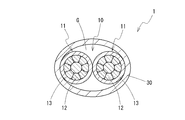
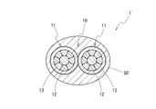
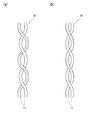
- FIG. 1 is a cross-sectional view showing a communication wire according to an embodiment of the present invention, in which a sheath is provided as a loose jacket. It is sectional drawing which shows the electric wire for communication in which the sheath was provided as a solid jacket. It is a figure explaining two types of twist structures about a twist line, (a) is showing the 1st twist structure (without twist), (b) has shown the 2nd twist structure (with twist). In the figure, a dotted line is a guide which shows the part which falls in the same position centering on the axis of an electric insulated wire along the axis of an electric insulated wire.
- FIG. 1 shows a cross-sectional view of a communication wire 1 according to an embodiment of the present invention.
- the communication wire 1 has a twisted pair wire 10 in which a pair of insulated wires 11 and 11 are twisted together.
- Each insulated wire 11 has a conductor 12 and an insulation coating 13 that covers the outer periphery of the conductor 12.
- the electric wire 1 for communication coats the outer periphery of the whole twisted pair wire 10, and has the sheath 30 which consists of insulating materials.
- the communication wire 1 has a characteristic impedance in the range of 100 ⁇ 10 ⁇ .
- the characteristic impedance of 100 ⁇ 10 ⁇ is a value required for the wire for Ethernet communication.
- the communication wire 1 can be suitably used for high speed communication in an automobile or the like by having such a characteristic impedance.
- the conductor 12 of the insulated wire 11 constituting the twisted pair wire 10 is made of a metal wire having a tensile strength of 400 MPa or more.
- a metal wire As a specific metal wire, a copper alloy wire containing Fe and Ti as described later, and a copper alloy wire containing Fe, P, and Sn can be exemplified.
- the tensile strength of the conductor 12 is more preferably 440 MPa or more, and further preferably 480 MPa or more.
- the conductor 12 Since the conductor 12 has a tensile strength of 400 MPa or more, and further 440 MPa or more, 480 MPa or more, the tensile strength required for the wire can be maintained even if the diameter is reduced.
- the diameter of the conductor 12 By reducing the diameter of the conductor 12, the distance between the two conductors 12 and 12 constituting the twisted pair wire 10 (the distance connecting the centers of the conductors 12 and 12) becomes close, and the characteristic impedance of the communication wire 1 become larger.
- the diameter of the conductor 12 can be reduced to such an extent that the cross-sectional area of the conductor is less than 0.22 mm 2 , and further 0.15 mm 2 or less and 0.13 mm 2 or less.
- the outer diameter of the conductor 12 can be 0.55 mm or less, further 0.50 mm or less, and 0 or 45 mm or less. If the diameter of the conductor 12 is excessively reduced, maintenance of strength becomes difficult and the characteristic impedance of the communication wire 1 becomes too large, so the conductor cross-sectional area is preferably set to 0.08 mm 2 or more.
- the communication wire 1 can be obtained even if the thickness of the insulating coating 13 covering the outer periphery of the conductor 12 is reduced to 0.30 mm or less, for example. In this case, it is easy to secure a characteristic impedance of 100 ⁇ 10 ⁇ . In the case of a conventional general copper wire, it is difficult to use the conductor cross-sectional area as less than 0.22 mm 2 due to the low tensile strength.
- the conductor 12 preferably has a breaking elongation of 7% or more.
- high tensile strength conductors have low toughness and often have low impact resistance when force is applied rapidly.
- the conductor 12 having a high tensile strength of 400 MPa or more has a breaking elongation of 7% or more, the process of assembling the wire harness from the communication wire 1 and the assembly of the wire harness
- the conductor 12 can exhibit high impact resistance even if an impact is applied to the conductor 12 in the process of 3.
- the breaking elongation of the conductor 12 is more preferably 10% or more.
- the conductor 12 may be a single wire, but is preferably a stranded wire in which a plurality of strands are twisted together from the viewpoint of enhancing the flexibility and the like. In this case, after the strands are twisted together, compression molding may be performed to form a compressed stranded wire. By compression molding, the outer diameter of the conductor 12 can be reduced. In addition, when the conductor 12 is formed of a stranded wire, as long as the conductor 12 as a whole has a tensile strength of 400 MPa or more, it may be all the same strand or may be two or more types of strands.
- a strand composed of a copper alloy containing Fe and Ti as described later, or a copper alloy containing Fe and P, Sn, and metals such as SUS and other metals other than copper alloys can be illustrated.
- the insulation coating 13 of the insulated wire 11 may be made of any insulating polymer material. From the viewpoint of securing a predetermined high value as the characteristic impedance, the insulating coating 13 preferably has a relative dielectric constant of 4.0 or less.
- a polymer material polyolefins such as polyethylene and polypropylene, polyvinyl chloride, polystyrene, polytetrafluoroethylene, polyphenylene sulfide and the like can be mentioned.
- the insulated wire 11 may optionally contain an additive such as a flame retardant, in addition to the polymer material.
- the thickness of the insulating coating 13 necessary for securing a predetermined characteristic impedance by the effect of reducing the diameter of the conductor 12 and raising the characteristic impedance by the approach between the conductors 12 and 12 Can be made smaller.
- the thickness of the insulating coating 13 is preferably 0.30 mm or less, more preferably 0.25 mm or less, and 0.20 mm or less. If the thickness of the insulating coating 13 is too thin, it becomes difficult to secure a characteristic impedance of a necessary size, so the thickness of the insulating coating 13 is preferably larger than 0.15 mm.
- the entire diameter of the insulated wire 11 is reduced.
- the outer diameter of the insulated wire 11 can be 1.05 mm or less, further 0.95 mm or less, and 0.85 mm or less.
- the diameter of the insulated wire 11 can be reduced.
- the uniformity of the thickness (insulation thickness) of the insulating coating 13 be high over the entire circumference of the conductor 12. That is, it is preferable that the uneven thickness be small. Then, the eccentricity of the conductor 12 is reduced, and when the twisted pair wire 10 is configured, the symmetry of the position of the conductor 12 in the twisted wire pair 10 is increased. As a result, the transmission characteristics of the communication wire 1, particularly, the mode conversion characteristics can be enhanced.
- the eccentricity ratio of each insulated wire 11 may be 65% or more, more preferably 75% or more.
- the eccentricity factor is calculated as [minimum insulation thickness] / [maximum insulation thickness] ⁇ 100%.
- the twisted wire 10 can be formed by twisting two insulated wires 11, and the twisting pitch can be set according to the outer diameter of the insulated wire 11 and the like. it can. However, by setting the twist pitch to 60 times or less, preferably 45 times or less, and more preferably 30 times or less of the outer diameter of the insulated wire 11, looseness of the twist structure can be effectively suppressed. Looseness of the twist structure can lead to variations in characteristic impedance of the communication wire 1 and various transmission characteristics and to changes with time. In particular, as described later, when the sheath 30 is of a loose jacket type, the presence of the air gap G between the sheath 30 and the twisted pair wire 10 makes the twin twisting more than that of the solid jacket type.
- the twist pitch is preferably at least 8 times the outer diameter of the insulated wire 11, more preferably Is preferably 12 times or more and 15 times or more.
- the following two structures can be illustrated as a twisting structure of the two insulated wires 11 in the twisted pair wire 10.
- the first twisting structure as shown in FIG. 3A, no twisting structure centered on the twisting axis is added to each insulated wire 11, and an insulated wire centered on the axis of the insulated wire 11 itself
- the relative top, bottom, left, and right directions of the 11 parts do not change along the twisting axis. That is, in the whole area of the twisting structure, the portions corresponding to the same position around the axis of the insulated wire 11 always point in the same direction, for example, upward.
- the second twisting structure as shown in FIG. 3B, a twisting structure is added to each insulated wire 11 with the twisting axis as the center, and the axis of the insulated wire 11 itself is the center
- the relative vertical and horizontal directions of each part of the insulated wire 11 change along the twisting axis. That is, in the twisting structure, the direction in which the portions that correspond to the same position centering on the axis of the insulated wire 11 are changed in the vertical and horizontal directions.
- the difference between the lengths of the two insulated wires 11 constituting the twisted pair wire 10 (difference in wire length) be smaller.
- the symmetry of the two insulated wires 11 can be raised, and the transmission characteristics, in particular, the mode conversion characteristics can be improved.
- the wire length difference per 1 m of twisted wire pair is suppressed to 5 mm or less, more preferably 3 mm or less, the influence of the wire length difference can be easily suppressed.
- the sheath 30 is provided for the purpose of protection of the twisted pair wire 10, holding of the twist structure, and the like.
- the sheath 30 is provided as a loose jacket and accommodates the twisted pair 10 in a hollow cylindrically shaped space.
- the sheath 30 is in contact with the insulated wire 11 constituting the twisted pair wire 10 only in a partial region along the circumferential direction of the inner peripheral surface, and in the other region, the sheath 30 and the insulated wire 11 are There is an air gap G between them, and a layer of air is formed. Details of the configuration of the sheath 30 will be described later.
- the sheath by the cutting operation for forming the cross section is embedded in a resin such as an acrylic resin so that the resin does not penetrate into the inner space of the sheath 30 so that deformation of the twisted pair 30 or the twisted wire 10 does not disturb accurate evaluation. It is preferable to perform the cutting operation after fixing in the state. In the cut surface, the area in which the acrylic resin is present is the area originally having the void G.
- a shield made of a conductive material surrounding the twisted pair wire 20 is not provided inside the sheath 30, and The sheath 30 directly surrounds the outer periphery.
- the shield plays a role of shielding noise from the outside and the noise from the outside with respect to the twisted wire pair 10, but the communication wire 1 according to the present embodiment has a condition in which the influence of the noise is not serious. It is assumed to be used in the case and no shield is provided.
- the sheath 30 directly coats the outer periphery of the twisted pair 20 through the air gap G without a member.
- the conductor 12 of the insulated wire 11 constituting the twisted pair wire 10 has a tensile strength of 400 MPa or more. Even if the diameter of the conductor 12 is reduced, it is easy to maintain sufficient strength as a wire for automobile. By reducing the diameter of the conductor 12, the distance between the two conductors 12, 12 constituting the twisted pair wire 10 becomes close. As the distance between the two conductors 12 and 12 decreases, the characteristic impedance of the communication wire 1 increases.
- the layer of the insulation coating 13 of the insulated wire 11 constituting the twisted pair wire 10 becomes thinner, the characteristic impedance becomes smaller, but in the communication wire 1, due to the effect of the approach accompanying the reduction of the diameter of the conductors 12,12, Even if the thickness of the insulating coating 13 is reduced to, for example, 0.30 mm or less, it is possible to secure a characteristic impedance of 100 ⁇ 10 ⁇ in the communication wire 1.
- the wire diameter (finished diameter) of the communication wire 1 as a whole can be reduced.
- the wire diameter of the communication wire 1 can be set to 2.9 mm or less, and further to 2.5 mm or less.
- the communication wire 1 is preferably reduced in diameter while maintaining a predetermined characteristic impedance value, so that the communication wire 1 is suitably used for high-speed communication in a limited space such as an automobile. be able to.
- the reduction in diameter of the conductor 12 and the reduction in thickness of the insulating coating 13 of the insulated wire 11 are effective not only for reducing the diameter of the communication wire 1 but also for reducing the weight of the communication wire 1.
- the weight of the communication wire 1 for example, when the communication wire 1 is used for communication in a car, the weight of the whole vehicle can be reduced, which leads to reduction in fuel consumption of the vehicle.
- the electric wire 1 for communication will have high breaking strength.
- the breaking strength can be 100 N or more, and further 140 N or more.
- the terminal can exhibit high gripping force with respect to the terminal or the like. That is, it becomes easy to prevent breakage of the communication wire 1 at a portion where a terminal or the like is attached to the terminal.
- transmission characteristics other than the characteristic impedance that is, transmission loss (IL), reflection loss (RL), transmission mode It is desirable that transmission characteristics such as conversion (LCTL) and reflection mode conversion (LCL) also satisfy predetermined levels.
- the sheath 30 of the loose jacket type configuration makes the insulation coating 13 of the insulated wire 11 less than 0.25 mm, and even 0.15 mm or less,
- the level of IL ⁇ 0.68 dB / m (66 MHz), RL ⁇ 20.0 dB (20 MHz), LCTL ⁇ 46.0 dB (50 MHz), and LCL ⁇ 46.0 dB (50 MHz) can be satisfied.
- the sheath 30 is provided as a loose jacket, and a gap G is present between the sheath 30 and the insulated wire 11 constituting the twisted pair wire 10.
- the communication wire 1 'of a form which provides sheath 30' as a solid jacket can also be considered.
- the sheath 30 ' is in contact with the insulated wire 11 constituting the twisted pair wire 10 or is formed in a solid state to a position immediately thereabout, and between the sheath 30' and the insulated wire 11
- the voids are substantially absent except for the voids that are inevitably formed.
- the case where the sheath 30 is a loose jacket is more preferable than the case where the sheath 30 is a solid jacket.
- the characteristic impedance of the communication wire 1 is higher when the twisted pair wire 10 is surrounded by a material having a low dielectric constant (see equation (1) below), and a layer of air is present around the twisted wire pair 10
- the configuration of the loose jacket can make the characteristic impedance higher than in the case of the solid jacket in which the dielectric immediately exists on the outside of the twisted pair wire 10.
- the characteristic impedance of 100 ⁇ 10 ⁇ can be secured.
- the diameter of the insulated wire 11 can be reduced, and the outer diameter of the entire communication wire 1 can also be reduced.
- the thickness of the insulating coating 13 of the insulated wire 11 is The characteristic impedance of 100 ⁇ 10 ⁇ can be secured in the communication wire 1 even if it is less than 0.25 mm, and even 0.20 mm or less. In this case, the outer diameter of the entire communication wire 1 can be 2.5 mm or less.
- the weight reduction of the communication wire 1 as a whole It can contribute to low fuel consumption when used in automobiles.
- the sheath 30 of a loose jacket type since the sheath 30 has a hollow cylindrical shape, the communication wire 1 as a whole is easily influenced by an unintended bending or bending, but the tensile strength as the conductor 12 The point can be compensated by using a pressure of 400 MPa or more.
- the effective dielectric constant (see the following formula (1)) is smaller, and the characteristic impedance of the communication wire 1 is larger.
- the ratio of the area occupied by the void G to the area of the entire area surrounded by the outer peripheral edge of the sheath 30, ie, the cross section including the thickness of the sheath 30 If the area ratio is 8% or more, a sufficient air layer will be present around the twisted wire pair 10, and a characteristic impedance of 100 ⁇ 10 ⁇ can be easily secured.
- the outer peripheral area ratio of the air gap G is more preferably 15% or more.
- the outer peripheral area ratio of the gap G is preferably 30% or less, more preferably 23% or less.
- the ratio of the area occupied by the gap G (inner peripheral area ratio) can also be used.
- the inner peripheral area ratio of the air gap G may be 26% or more, more preferably 39% or more.
- the inner circumferential area rate may be suppressed to 56% or less, more preferably 50% or less.
- the thickness of the sheath 30 also affects the effective dielectric constant and the characteristic impedance of the communication wire 1, and therefore, as an index for securing a sufficient characteristic impedance, an air gap with the outer peripheral area ratio as an index rather than the inner peripheral area ratio It is preferable to set G. However, particularly when the sheath 30 is thick, the thickness of the sheath 30 has less influence on the characteristic impedance of the communication wire 1, so the inner circumferential area ratio is also a good index.
- the ratio of the gap G in the cross section may not be constant at each portion within one pitch of the twisted pair wire 10.
- the ratio of the gap G may be evaluated using the volume in the length region of one pitch of the twisted pair wire 10 as an index.
- the ratio of the volume occupied by the air gap G (outer peripheral volume ratio) to the volume of the region surrounded by the outer peripheral surface of the sheath 30 is 7% or more Preferably, it is 14% or more. Further, the outer peripheral volume ratio may be 29% or less, more preferably 22% or less. Alternatively, the ratio of the volume occupied by the air gap G (inner peripheral volume ratio) of the volume of the region surrounded by the inner peripheral surface of the sheath 30 in the length region of one pitch of the twisted wire 10 is 25% or more More preferably, it is 38% or more. Further, the inner peripheral volume ratio may be 55% or less, more preferably 49% or less.
- the effective dielectric constant represented by the following equation 1 is smaller.
- the effective dielectric constant depends not only on the size of the air gap G but also on parameters such as the material and thickness of the sheath 30, but the effective dielectric constant is preferably 7.0 or less, more preferably 6.0 or less, By selecting the size of the air gap G and other parameters, the characteristic impedance of the communication wire 1 can be easily increased to an area of 100 ⁇ 10 ⁇ .
- the effective dielectric constant is preferably 1.5 or more, more preferably 2.0 or more from the viewpoint of the productivity of the communication wire 1 and the reliability of the wire and from the viewpoint of securing a certain thickness of the insulation coating. You should The size of the air gap G can be controlled by the conditions (die / point shape, extrusion temperature, etc.) when forming the sheath 30 by extrusion.
- ⁇ eff is an effective dielectric constant
- d is a conductor diameter
- D is a wire outer diameter
- ⁇ 0 is a constant.
- the sheath 30 is in contact with the insulated wire 11 in a partial region of the inner circumferential surface. In these regions, as long as the sheath 30 is firmly in close contact with the insulated wire 11, the sheath 30 holds down the twisted wire 10, thereby causing displacement of the twisted wire 10 in the inner space of the sheath 30 or twisted wire. It is possible to suppress the phenomenon such as 10 looseness of the twist structure.
- the adhesion of the sheath 30 to the insulated wire 11 is 4 N or more, more preferably 7 N or more and 8 N or more, these phenomena are suppressed, and the distance between the two insulated wires 11 is a small value, for example By maintaining substantially 0 mm, it is possible to effectively suppress variations in characteristic impedance and various transmission characteristics and changes over time.
- the adhesion of the sheath 30 is too large, the processability of the communication wire 1 is deteriorated, so the adhesion may be suppressed to 70 N or less.
- the adhesion of the sheath 30 to the insulated wire 11 can be adjusted by changing the extrusion temperature of the resin material when forming the sheath 30 on the outer periphery of the twisted pair wire 10 by extruding the resin material.
- the adhesion can be evaluated as, for example, the strength until the twisted wire 10 is pulled off by pulling the twisted wire 10 in a state where the sheath 30 is removed 30 mm from one end in the communication wire 1 having a total length of 150 mm.
- the length (contact ratio) of the portion in contact with the insulated wire 11 is 0.5% or more in the cross section substantially perpendicular to the axis of the communication wire 1. If the content is preferably 2.5% or more, those phenomena can be effectively suppressed. On the other hand, if the contact ratio is set to 80% or less, more preferably 50% or less, the gap G can be easily secured.
- the contact ratio preferably satisfies the above condition as an average value of the length region of one pitch of the twisted wire pair 10, and satisfies the above condition over the entire length region of one pitch. And is more preferable.
- the thickness of the sheath 30 may be selected as appropriate.
- the influence of noise from the outside of the communication wire 1 for example, the viewpoint of reducing the influence from other wires when the communication wire 1 is used in the state of a wire harness etc. together with the other wires, and wear resistance
- the thickness of the sheath may be 0.20 mm or more, more preferably 0.30 mm or more.
- the thickness of the sheath 30 may be 1.0 mm or less, more preferably 0.7 mm or less.
- the loose jacket type sheath 30 from the viewpoint of reducing the diameter of the communication wire 1, but as shown in FIG. It is also conceivable to use a solid jacket type sheath 30 '.
- the solid type sheath 30 ' can firmly fix the twisted pair wire 10 by the sheath 30', and it is easy to prevent phenomena such as displacement of the twisted pair wire 10 with respect to the sheath 30 'and looseness of the twist structure. .
- the sheath 30 is a loose-jacket type or a solid-jacket type sheath 30 can be controlled by the conditions (die / point shape, extrusion temperature, etc.) when forming the sheath by extrusion. Further, in a situation where there is no problem in the protection of the twisted pair wire 10 or the holding of the twist structure, the sheath 30 can be omitted, and it is not necessarily provided in the communication wire.
- the sheath 30 as well as the insulation coating 13 of the insulated wire 11 may be made of any polymer material. That is, examples of the polymer material include polyolefins such as polyethylene and polypropylene, polyvinyl chloride, polystyrene, polytetrafluoroethylene, polyphenylene sulfide and the like. Among these, from the viewpoint of increasing the characteristic impedance of the communication wire 1, it is particularly preferable to use a polyolefin which is a nonpolar polymer material.
- the sheath 30 may optionally contain an additive such as a flame retardant, in addition to the polymer material. Although the sheath 30 may be composed of a plurality of layers, it is preferable that the sheath 30 be composed of only one layer from the viewpoint of reducing the diameter and cost of the communication wire 1 by simplifying the configuration.
- the copper alloy wire mentioned as a first example here has the following component composition. Fe: 0.05% by mass or more, 2.0% by mass or less Ti: 0.02% by mass or more, 1.0% by mass or less Mg: 0% by mass or more, 0.6% by mass or less (containing Mg Not included))
- the balance consists of Cu and unavoidable impurities.
- the copper alloy wire having the above composition has very high tensile strength.
- the content of Fe is 0.8% by mass or more, and the content of Ti is 0.2% by mass or more, particularly high tensile strength can be achieved.
- the tensile strength can be increased by increasing the degree of wire drawing and reducing the wire diameter, or by performing heat treatment after wire drawing, and the conductor 11 having a tensile strength of 400 MPa or more can be obtained. .
- the copper alloy wire mentioned as a 2nd example has the following component compositions. Fe: 0.1 mass% or more, 0.8 mass% or less P: 0.03 mass% or more, 0.3 mass% or less Sn: 0.1 mass% or more, 0.4 mass% or less Remainder Is composed of Cu and unavoidable impurities.
- the copper alloy wire having the above composition has very high tensile strength.
- the content of Fe is 0.4% by mass or more and the content of P is 0.1% by mass or more, particularly high tensile strength can be achieved.
- the tensile strength can be increased by increasing the degree of wire drawing and reducing the wire diameter, or by performing heat treatment after wire drawing, and the conductor 11 having a tensile strength of 400 MPa or more can be obtained. .
- the obtained conductor had a conductor cross-sectional area of 0.13 mm 2 and an outer diameter of 0.45 mm.
- the tensile strength and the breaking elongation of the copper alloy conductor thus obtained were evaluated according to JIS Z 2241. At this time, the distance between the marks was 250 mm, and the tensile speed was 50 mm / min. As a result of evaluation, the tensile strength was 490 MPa and the elongation at break was 8%.
- the characteristic impedance of the obtained communication wire was measured. The measurement was performed by the open / short method using an LCR meter.
- samples A1 to A3 using copper alloy conductors and having a conductor cross-sectional area smaller than 0.22 mm 2 are used as conductors and a pure copper wire is used.
- the behavior of the above-mentioned characteristic impedance is interpreted as a result that the diameter of the conductor can be reduced when using a copper alloy wire as the conductor than when using a pure copper wire, and the distance between the conductors is closer. Ru.
- the thickness of the insulation coating can be less than 0.30 mm while maintaining the characteristic impedance of 100 ⁇ 10 ⁇ , and 0.18 mm for the thinnest. It has become possible.
- by thinning the insulation coating it is possible to reduce the finished outer diameter of the communication wire together with the effect of reducing the diameter of the conductor itself.
- characteristic impedances of substantially the same value are obtained for the sample A3 using a copper alloy conductor as the conductor and the sample A6 using a pure copper wire.
- the finished outer diameters of the two are compared, the finished outer diameter of the communication wire is reduced by about 20% in the sample A3 using the copper alloy conductor because the thinning of the conductor can be achieved. There is.
- the characteristic impedance is out of the range of 100 ⁇ 10 ⁇ . That is, the characteristic impedance in the range of 100 ⁇ 10 ⁇ can be obtained by appropriately selecting the thickness of the insulation coating after reducing the diameter of the conductor using a copper alloy.
- a communication wire was produced in the same manner as the samples A1 to A4 in the above-mentioned test [1].
- the eccentricity of the insulated wire was set to 80%, and the twisted structure of the twisted pair was made the first twisted structure (without twist).
- two types of sheaths a loose jacket type as shown in FIG. 1 and a solid jacket type as shown in FIG. 2 were prepared.
- the sheath was made of polypropylene.
- the thickness of the sheath was determined by the die point shape used, and was 0.4 mm for the loose jacket type and 0.5 mm for the thinnest type.
- the size of the air gap between the loose jacket type sheath and the insulated wire was 23% in the outer peripheral area ratio, and the adhesion of the sheath to the insulated wire was 15N. Moreover, several samples which changed the thickness of the insulation coating of the insulated wire about each case were produced.
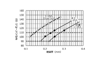
- FIG. 4 shows the insulation thickness and the characteristic impedance obtained by the above equation (1) which is known as the theoretical expression of the characteristic impedance of the communication wire having the twisted pair when no sheath is provided.
- the approximate curve based on Formula (1) is shown also to the measurement result in the case of having each sheath. Further, the broken line in the drawing indicates a range in which the characteristic impedance is 100 ⁇ 10 ⁇ .
- the characteristic impedance in the case where the insulation thickness is the same is lowered corresponding to the increase of the effective dielectric constant.
- the degree of the decrease is smaller in the case of the loose jacket type than in the case of the solid jacket type of the sheath, and a large characteristic impedance is obtained.
- the insulation thickness required to obtain the same characteristic impedance may be smaller.
- the characteristic impedance is 100 ⁇ in the case of the loose jacket type, in the case of the insulation thickness of 0.20 mm, and in the case of the solid jacket type, in the case of the insulation thickness of 0.25 mm.
- the insulation thickness and the outer diameter and mass of the communication wire are summarized in Table 2 below.
- the insulation thickness is reduced by 25%
- the outer diameter of the communication wire is 7.4%
- the mass is reduced by 27%, compared to the solid jacket type. ing. That is, by using the loose jacket type sheath, even if the insulation thickness of the insulated wire constituting the twisted pair is reduced, it is possible to obtain a sufficient characteristic impedance, and as a result, the entire communication wire It has been verified that the outer diameter can be reduced and the mass can be further reduced.
- the size of the void was measured for each of the samples prepared above. Under the present circumstances, after embedding the electric wire for communication of each sample in acrylic resin and fixing, it cut
- the characteristic impedance in the range of 100 ⁇ 10 ⁇ is stably obtained.
- the effective dielectric constant becomes too large due to the small size of the air gap, and the characteristic impedance does not reach 100 ⁇ 10 ⁇ .
- the characteristic impedance exceeds the range of 100 ⁇ 10 ⁇ to the high side.
- the adhesion of the sheath was measured for each of the samples prepared above.
- the adhesion of the sheath was evaluated in a sample with a total length of 150 mm in a state where the sheath was removed 30 mm from one end, the insulated wire was pulled, and the strength until the insulated wire fell off was evaluated.
- changes in characteristic impedance were measured under conditions simulating use over time. Specifically, the communication wire for each sample is bent 200 times at an angle of 90 ° along a mandrel with an outer diameter of 25 mm, and then the characteristic impedance of the bent portion is measured, and the amount of change from before bending is recorded. did.
- the change of the characteristic impedance by the influence of other wires was evaluated. Specifically, first, the characteristic impedance in the state of an independent single wire was measured for the communication wire of each sample. In addition, the characteristic impedance was measured even in a state in which the other electric wires were embraced. Here, in a state in which the other electric wires are embraced, the six other electric wires (PVC electric wire with an outer diameter of 2.6 mm) are arranged in contact with the outer periphery of the sample electric wire at approximately the center of the sample electric wire. What was fixed by winding a PVC tape was prepared. And based on the value of the characteristic impedance in the state of a single wire, the change amount of the characteristic impedance in the state which carried in the other electric wire was recorded.
- Table 6 shows the measurement results of the eccentricity and the mode conversion characteristics. As the value of each mode conversion, the absolute value indicates the minimum value in the range of 1 to 50 MHz.
- Table 7 summarizes the relationship between the twist pitch of the twisted pair and the amount of change in the characteristic impedance.
- the twist pitch of the twisted pair is indicated by a value based on the outer diameter (0.85 mm) of the insulated wire, that is, how many times the outer diameter of the insulated wire is.
- Table 8 shows the relationship between the type of twist structure and the fluctuation range of the characteristic impedance.
- the sheath for covering the outer periphery of the twisted pair wire may be provided not only as a loose jacket type but also as a full type according to the degree of request for reduction in diameter of the communication wire. Moreover, it can also be set as the structure which does not provide a sheath. That is, it has a twisted pair formed by twisting a pair of insulated wires consisting of a conductor having a tensile strength of 400 MPa or more and an insulating coating covering the outer periphery of the conductor, and has a characteristic impedance of 100 ⁇ 10 ⁇ .
- the communication wire can be in the range of In this case, the thickness of the insulation coating, the composition and elongation at break of the conductor, the outer diameter and eccentricity of the insulated wire, the twist structure and twist pitch of the twisted wire, the thickness and adhesion of the sheath, the outside of the insulated wire Preferred configurations applicable to each part of the communication wire, such as diameter and breaking strength, are the same as above.
- it has a twisted pair formed by twisting a pair of insulated wires consisting of a conductor with a tensile strength of 400 MPa or more and an insulating coating covering the outer periphery of the conductor, and has a characteristic impedance of 100 ⁇ 10 ⁇ .
Landscapes
- Physics & Mathematics (AREA)
- Electromagnetism (AREA)
- Engineering & Computer Science (AREA)
- Manufacturing & Machinery (AREA)
- Communication Cables (AREA)
- Insulated Conductors (AREA)
- Conductive Materials (AREA)
Priority Applications (16)
| Application Number | Priority Date | Filing Date | Title |
|---|---|---|---|
| US16/070,048 US10818412B2 (en) | 2016-03-31 | 2016-12-02 | Communication cable |
| CN201680083363.3A CN108780680B (zh) | 2016-03-31 | 2016-12-02 | 通信用电线 |
| CN202011117675.6A CN112599297B (zh) | 2016-03-31 | 2016-12-02 | 通信用电线 |
| DE112016006665.1T DE112016006665T5 (de) | 2016-03-31 | 2016-12-02 | Kommunikationskabel |
| JP2016572775A JP6108057B1 (ja) | 2016-03-31 | 2016-12-02 | 通信用電線 |
| JP2018508394A JP6485591B2 (ja) | 2016-03-31 | 2016-12-21 | 通信用電線 |
| PCT/JP2016/088127 WO2017168881A1 (ja) | 2016-03-31 | 2016-12-21 | 通信用電線 |
| CN201680082773.6A CN108701515A (zh) | 2016-03-31 | 2016-12-21 | 通信用电线 |
| DE112016006142.0T DE112016006142T5 (de) | 2016-03-31 | 2016-12-21 | Kommunikationskabel |
| US15/565,526 US10553329B2 (en) | 2016-03-31 | 2016-12-21 | Communication cable having single twisted pair of insulated wires |
| KR1020197019783A KR20190085169A (ko) | 2016-03-31 | 2016-12-21 | 통신용 전선 |
| KR1020187022375A KR102001795B1 (ko) | 2016-03-31 | 2016-12-21 | 통신용 전선 |
| JP2017017102A JP2017188431A (ja) | 2016-03-31 | 2017-02-01 | 通信用電線 |
| JP2019029130A JP6696601B2 (ja) | 2016-03-31 | 2019-02-21 | 通信用電線 |
| US16/716,146 US10825577B2 (en) | 2016-03-31 | 2019-12-16 | Communication cable having single twisted pair of insulated wires |
| US17/024,893 US20210005348A1 (en) | 2016-03-31 | 2020-09-18 | Communication cable |
Applications Claiming Priority (2)
| Application Number | Priority Date | Filing Date | Title |
|---|---|---|---|
| JP2016071314 | 2016-03-31 | ||
| JP2016-071314 | 2016-03-31 |
Related Child Applications (2)
| Application Number | Title | Priority Date | Filing Date |
|---|---|---|---|
| US16/070,048 A-371-Of-International US10818412B2 (en) | 2016-03-31 | 2016-12-02 | Communication cable |
| US17/024,893 Continuation US20210005348A1 (en) | 2016-03-31 | 2020-09-18 | Communication cable |
Publications (1)
| Publication Number | Publication Date |
|---|---|
| WO2017168842A1 true WO2017168842A1 (ja) | 2017-10-05 |
Family
ID=59351343
Family Applications (2)
| Application Number | Title | Priority Date | Filing Date |
|---|---|---|---|
| PCT/JP2016/085960 Ceased WO2017168842A1 (ja) | 2016-03-31 | 2016-12-02 | 通信用電線 |
| PCT/JP2016/088127 Ceased WO2017168881A1 (ja) | 2016-03-31 | 2016-12-21 | 通信用電線 |
Family Applications After (1)
| Application Number | Title | Priority Date | Filing Date |
|---|---|---|---|
| PCT/JP2016/088127 Ceased WO2017168881A1 (ja) | 2016-03-31 | 2016-12-21 | 通信用電線 |
Country Status (6)
| Country | Link |
|---|---|
| US (4) | US10818412B2 (enExample) |
| JP (8) | JP6485591B2 (enExample) |
| KR (2) | KR102001795B1 (enExample) |
| CN (3) | CN112599297B (enExample) |
| DE (2) | DE112016006665T5 (enExample) |
| WO (2) | WO2017168842A1 (enExample) |
Cited By (9)
| Publication number | Priority date | Publication date | Assignee | Title |
|---|---|---|---|---|
| RU182083U1 (ru) * | 2018-02-07 | 2018-08-03 | Открытое акционерное общество Всероссийский научно-исследовательский, проектно-конструкторский и технологический институт кабельной промышленности | Кабель герметизированный для передачи данных |
| RU182084U1 (ru) * | 2018-02-07 | 2018-08-03 | Открытое акционерное общество Всероссийский научно-исследовательский, проектно-конструкторский и технологический институт кабельной промышленности | Кабель герметизированный для передачи данных |
| JP2020109756A (ja) * | 2019-01-04 | 2020-07-16 | 住友電気工業株式会社 | 多芯ケーブル及びその製造方法 |
| JP2021015749A (ja) * | 2019-07-16 | 2021-02-12 | 矢崎総業株式会社 | 差動伝送ケーブル及びワイヤーハーネス |
| WO2021171960A1 (ja) * | 2020-02-26 | 2021-09-02 | 株式会社オートネットワーク技術研究所 | 通信用電線 |
| WO2022202174A1 (ja) * | 2021-03-24 | 2022-09-29 | 株式会社オートネットワーク技術研究所 | 通信用電線 |
| JP2022142635A (ja) * | 2021-03-16 | 2022-09-30 | 古河電気工業株式会社 | 通信用電線 |
| JP2023090352A (ja) * | 2021-12-17 | 2023-06-29 | 矢崎総業株式会社 | 通信ケーブル及びそれを用いたワイヤーハーネス |
| WO2024171366A1 (ja) * | 2023-02-16 | 2024-08-22 | 矢崎総業株式会社 | 通信ケーブル及びそれを用いたワイヤーハーネス |
Families Citing this family (22)
| Publication number | Priority date | Publication date | Assignee | Title |
|---|---|---|---|---|
| US20170140450A1 (en) | 2015-11-17 | 2017-05-18 | Fazahl Ashby | Visual cable builder |
| JP6593778B2 (ja) * | 2016-02-05 | 2019-10-23 | 住友電気工業株式会社 | 被覆電線、端子付き電線、銅合金線、及び銅合金撚線 |
| US10818412B2 (en) | 2016-03-31 | 2020-10-27 | Autonetworks Technologies, Ltd. | Communication cable |
| CN111373492B (zh) | 2017-11-08 | 2021-12-03 | 株式会社自动网络技术研究所 | 电线导体、包覆电线、线束 |
| KR102181049B1 (ko) * | 2019-02-19 | 2020-11-19 | 엘에스전선 주식회사 | 이더넷 케이블 |
| JP7439100B2 (ja) * | 2019-02-19 | 2024-02-27 | エルエス ケーブル アンド システム リミテッド. | イーサネットケーブル |
| JP6955530B2 (ja) * | 2019-05-20 | 2021-10-27 | 矢崎総業株式会社 | 耐屈曲通信ケーブル及びワイヤハーネス |
| JP6957568B2 (ja) * | 2019-08-09 | 2021-11-02 | 株式会社オートネットワーク技術研究所 | 端子付き電線 |
| JP6936836B2 (ja) | 2019-08-09 | 2021-09-22 | 株式会社オートネットワーク技術研究所 | 端子付き電線 |
| JP7622633B2 (ja) * | 2019-08-30 | 2025-01-28 | 住友電気工業株式会社 | 多芯ケーブル、ハーネス |
| US11636958B2 (en) | 2019-09-04 | 2023-04-25 | Yazaki Corporation | Communication cable and wire harness |
| JP6987824B2 (ja) * | 2019-10-25 | 2022-01-05 | 矢崎総業株式会社 | 通信ケーブル及びワイヤハーネス |
| JP2021150230A (ja) * | 2020-03-23 | 2021-09-27 | 株式会社東芝 | 圧着判定方法 |
| JP7214689B2 (ja) * | 2020-08-28 | 2023-01-30 | 矢崎総業株式会社 | 圧縮撚線導体、圧縮撚線導体の製造方法、絶縁電線及びワイヤーハーネス |
| JP7244467B2 (ja) | 2020-09-16 | 2023-03-22 | 矢崎総業株式会社 | 樹脂組成物、並びにそれを用いた通信ケーブル及びワイヤーハーネス |
| JP2022151330A (ja) * | 2021-03-26 | 2022-10-07 | 古河電気工業株式会社 | 通信用電線、端子付き電線及びワイヤハーネス |
| JP7631995B2 (ja) | 2021-03-31 | 2025-02-19 | 株式会社オートネットワーク技術研究所 | 電線導体および絶縁電線 |
| JP7615842B2 (ja) | 2021-03-31 | 2025-01-17 | 株式会社オートネットワーク技術研究所 | 電線導体および絶縁電線 |
| WO2023068827A1 (ko) * | 2021-10-20 | 2023-04-27 | 엘에스전선 주식회사 | 이더넷 케이블 |
| JP2023067141A (ja) * | 2021-10-29 | 2023-05-16 | 古河電気工業株式会社 | 通信用電線 |
| WO2023090417A1 (ja) * | 2021-11-19 | 2023-05-25 | 昭和電線ケーブルシステム株式会社 | 通信ケーブルおよびその製造方法 |
| CN117059312A (zh) * | 2023-07-26 | 2023-11-14 | 上海蓝昊电气股份有限公司 | 辅助线、扁形电缆及圆形电缆 |
Citations (5)
| Publication number | Priority date | Publication date | Assignee | Title |
|---|---|---|---|---|
| JP2001148206A (ja) * | 1999-11-19 | 2001-05-29 | Hitachi Cable Ltd | 超極細銅合金線材及びその製造方法 |
| JP2005032583A (ja) * | 2003-07-07 | 2005-02-03 | Yazaki Corp | 自動車向け通信用シールド電線 |
| JP2008130347A (ja) * | 2006-11-21 | 2008-06-05 | Auto Network Gijutsu Kenkyusho:Kk | シールド付ツイスト電線 |
| JP2015130326A (ja) * | 2013-12-10 | 2015-07-16 | デルファイ・テクノロジーズ・インコーポレーテッド | 遮蔽ケーブルアセンブリ |
| JP2015170431A (ja) * | 2014-03-06 | 2015-09-28 | 株式会社オートネットワーク技術研究所 | ツイストケーブル |
Family Cites Families (97)
| Publication number | Priority date | Publication date | Assignee | Title |
|---|---|---|---|---|
| US3522112A (en) | 1967-06-26 | 1970-07-28 | Olin Corp | Process for treating copper base alloy |
| US3489844A (en) | 1968-03-25 | 1970-01-13 | Dynatronic Cable Eng Corp | Multiple-pair digital data transmission cable |
| US3515796A (en) | 1969-04-07 | 1970-06-02 | Southwire Co | Insulated telephone cable |
| USRE27854E (en) | 1972-10-12 | 1973-12-25 | Insulated telephone cable | |
| US4506235A (en) | 1982-02-23 | 1985-03-19 | Ferdy Mayer | EMI Protected cable, with controlled symmetrical/asymmetrical mode attenuation |
| JPS6039139A (ja) | 1983-08-12 | 1985-02-28 | Mitsui Mining & Smelting Co Ltd | 耐軟化高伝導性銅合金 |
| JPS6164834A (ja) | 1984-09-04 | 1986-04-03 | Nippon Mining Co Ltd | 耐熱高力高導電性銅合金 |
| US4777325A (en) | 1987-06-09 | 1988-10-11 | Amp Incorporated | Low profile cables for twisted pairs |
| US4873393A (en) | 1988-03-21 | 1989-10-10 | American Telephone And Telegraph Company, At&T Bell Laboratories | Local area network cabling arrangement |
| JPH0710141B2 (ja) | 1989-09-21 | 1995-02-01 | 株式会社日立製作所 | ケーブルの端末処理方法およびその端末処理装置 |
| US5327513A (en) * | 1992-05-28 | 1994-07-05 | Raychem Corporation | Flat cable |
| US5283390A (en) | 1992-07-07 | 1994-02-01 | W. L. Gore & Associates, Inc. | Twisted pair data bus cable |
| JPH06164834A (ja) | 1992-11-14 | 1994-06-10 | Nisca Corp | 画像読み取り装置 |
| JPH0660739A (ja) * | 1992-08-12 | 1994-03-04 | Sumitomo Wiring Syst Ltd | 自動車用電線導体 |
| JPH0660740A (ja) | 1992-08-12 | 1994-03-04 | Hitachi Cable Ltd | 無遮蔽対型ケーブル |
| US6222129B1 (en) | 1993-03-17 | 2001-04-24 | Belden Wire & Cable Company | Twisted pair cable |
| US5606151A (en) | 1993-03-17 | 1997-02-25 | Belden Wire & Cable Company | Twisted parallel cable |
| US5399813A (en) | 1993-06-24 | 1995-03-21 | The Whitaker Corporation | Category 5 telecommunication cable |
| JP3373901B2 (ja) | 1993-08-06 | 2003-02-04 | 古河電気工業株式会社 | スピーカー用複合ケーブル |
| US5424491A (en) | 1993-10-08 | 1995-06-13 | Northern Telecom Limited | Telecommunications cable |
| JPH0850820A (ja) | 1994-08-09 | 1996-02-20 | Hitachi Cable Ltd | 高速ディジタル信号伝送用無遮蔽平衡対型ケーブル |
| US5600097A (en) | 1994-11-04 | 1997-02-04 | Lucent Technologies Inc. | Fire resistant cable for use in local area network |
| US5597981A (en) | 1994-11-09 | 1997-01-28 | Hitachi Cable, Ltd. | Unshielded twisted pair cable |
| US5619016A (en) | 1995-01-31 | 1997-04-08 | Alcatel Na Cable Systems, Inc. | Communication cable for use in a plenum |
| US5770820A (en) | 1995-03-15 | 1998-06-23 | Belden Wire & Cable Co | Plenum cable |
| JPH0992050A (ja) | 1995-09-28 | 1997-04-04 | Sumitomo Wiring Syst Ltd | 高周波用通信ケーブル |
| US5767441A (en) | 1996-01-04 | 1998-06-16 | General Cable Industries | Paired electrical cable having improved transmission properties and method for making same |
| US5821467A (en) | 1996-09-11 | 1998-10-13 | Belden Wire & Cable Company | Flat-type communication cable |
| US6194663B1 (en) | 1997-02-28 | 2001-02-27 | Lucent Technologies Inc. | Local area network cabling arrangement |
| JP3846757B2 (ja) * | 1997-08-06 | 2006-11-15 | 古河電気工業株式会社 | ケーブル |
| DE19815568C2 (de) | 1998-03-31 | 2000-06-08 | Bebig Isotopentechnik Und Umwe | Verfahren zur Herstellung von medizinischen radioaktiven Ruthenium-Strahlenquellen durch elektrolytische Abscheidung von radioaktivem Ruthenium auf einem Träger, mit diesem Verfahren hergestellte Strahlenquellen und Elektrolysezelle zur Erzeugung von radioaktiven Ruthenium-Schichten |
| US6211467B1 (en) | 1998-08-06 | 2001-04-03 | Prestolite Wire Corporation | Low loss data cable |
| US6096977A (en) | 1998-09-04 | 2000-08-01 | Lucent Technologies Inc. | High speed transmission patch cord cable |
| US6323427B1 (en) | 1999-05-28 | 2001-11-27 | Krone, Inc. | Low delay skew multi-pair cable and method of manufacture |
| US6153826A (en) | 1999-05-28 | 2000-11-28 | Prestolite Wire Corporation | Optimizing lan cable performance |
| KR100884122B1 (ko) | 1999-05-28 | 2009-02-17 | 에이디씨 디지털 커뮤니케이션즈 인코포레이티드 | 패치 케이블 |
| CZ301027B6 (cs) | 1999-06-18 | 2009-10-14 | Belden Wire & Cable Company | Datový kabel a zpusob jeho výroby |
| US6686537B1 (en) | 1999-07-22 | 2004-02-03 | Belden Wire & Cable Company | High performance data cable and a UL 910 plenum non-fluorinated jacket high performance data cable |
| JP2001283649A (ja) | 2000-03-30 | 2001-10-12 | Sumitomo Electric Ind Ltd | 複数心ケーブル及びケーブルバンドル |
| US6632300B2 (en) | 2000-06-26 | 2003-10-14 | Olin Corporation | Copper alloy having improved stress relaxation resistance |
| DE60233112D1 (de) * | 2001-02-28 | 2009-09-10 | Prysmian Spa | Nachrichtenkabel und anlage zur herstellung von solche kabel |
| JP2003036739A (ja) | 2001-07-19 | 2003-02-07 | Fujikura Ltd | 通信用ケーブル |
| BR0200850A (pt) * | 2002-03-18 | 2003-11-11 | Pirelli Telecomunicacoees Cabo | Cabo de condutores metálicos trançados de superior desempenho elétrico para uso em sistemas digitais |
| CA2497819A1 (en) | 2002-09-13 | 2004-03-25 | Ronald N. Caron | Age-hardening copper-base alloy and processing |
| US7015397B2 (en) | 2003-02-05 | 2006-03-21 | Belden Cdt Networking, Inc. | Multi-pair communication cable using different twist lay lengths and pair proximity control |
| US20040238086A1 (en) | 2003-05-27 | 2004-12-02 | Joseph Saleh | Processing copper-magnesium alloys and improved copper alloy wire |
| JP4140471B2 (ja) * | 2003-07-22 | 2008-08-27 | 住友電気工業株式会社 | 銅の精錬方法 |
| WO2005013292A1 (en) | 2003-07-28 | 2005-02-10 | Belden Cdt Networking, Inc. | Skew adjusted data cable |
| US7214884B2 (en) | 2003-10-31 | 2007-05-08 | Adc Incorporated | Cable with offset filler |
| MXPA04002843A (es) | 2004-03-26 | 2005-09-28 | Servicios Condumex Sa | Cable aereo reforzado multiple para telecomunicaciones de planta externa. |
| JP2006019080A (ja) | 2004-06-30 | 2006-01-19 | Hitachi Cable Ltd | 差動信号伝送ケーブル |
| US7256351B2 (en) | 2005-01-28 | 2007-08-14 | Superior Essex Communications, Lp | Jacket construction having increased flame resistance |
| US7737358B2 (en) | 2007-04-12 | 2010-06-15 | Commscope, Inc. Of North Carolina | Data transmission cable pairs and cables and methods for forming the same |
| KR100825408B1 (ko) | 2007-04-13 | 2008-04-29 | 엘에스전선 주식회사 | 고속 통신용 케이블 |
| US20080311328A1 (en) | 2007-06-13 | 2008-12-18 | Hitoshi Kimura | Non-halogen flame retardant resin composition and non-halogen flame retardant electric wire and cable |
| JP2009167450A (ja) * | 2008-01-11 | 2009-07-30 | Sumitomo Electric Ind Ltd | 銅合金及びその製造方法 |
| US7982132B2 (en) | 2008-03-19 | 2011-07-19 | Commscope, Inc. Of North Carolina | Reduced size in twisted pair cabling |
| JP2011054410A (ja) | 2009-09-01 | 2011-03-17 | Yoshinokawa Electric Wire & Cable Co Ltd | 高周波用極細ペアケーブル及びその製造方法 |
| JP5513075B2 (ja) | 2009-10-29 | 2014-06-04 | 三菱電線工業株式会社 | 自動車用電線及びその製造方法 |
| JP5740817B2 (ja) * | 2010-02-12 | 2015-07-01 | 日立金属株式会社 | 高電圧キャブタイヤケーブル |
| US8981216B2 (en) * | 2010-06-23 | 2015-03-17 | Tyco Electronics Corporation | Cable assembly for communicating signals over multiple conductors |
| US8440909B2 (en) | 2010-07-01 | 2013-05-14 | General Cable Technologies Corporation | Data cable with free stripping water blocking material |
| JP6002360B2 (ja) | 2010-07-21 | 2016-10-05 | 矢崎総業株式会社 | 端子付電線 |
| US8431825B2 (en) * | 2010-08-27 | 2013-04-30 | Belden Inc. | Flat type cable for high frequency applications |
| WO2012030367A1 (en) | 2010-08-31 | 2012-03-08 | 3M Innovative Properties Company | Shielded electrical cable in twinaxial configuration |
| US9136043B2 (en) | 2010-10-05 | 2015-09-15 | General Cable Technologies Corporation | Cable with barrier layer |
| JP5621538B2 (ja) | 2010-11-18 | 2014-11-12 | 日本精工株式会社 | レゾルバ用シールドケーブル及びレゾルバ |
| JP2012146431A (ja) | 2011-01-11 | 2012-08-02 | Auto Network Gijutsu Kenkyusho:Kk | 電線導体及び絶縁電線 |
| JP5155464B2 (ja) | 2011-04-11 | 2013-03-06 | 住友電気工業株式会社 | アルミニウム合金線、アルミニウム合金撚り線、被覆電線、及びワイヤーハーネス |
| JP2012248310A (ja) | 2011-05-25 | 2012-12-13 | Hitachi Cable Ltd | 耐湿性を有する、撚り線導体を用いた対撚線及び対撚線ケーブル |
| JP5817674B2 (ja) * | 2011-09-16 | 2015-11-18 | 日立金属株式会社 | ノンドレイン差動信号伝送用ケーブル及びそのグランド接続構造 |
| JP2013098127A (ja) | 2011-11-04 | 2013-05-20 | Hitachi Cable Ltd | ジェリー撚線導体使用対撚線及びこれを用いたケーブル |
| US9196400B2 (en) | 2011-12-21 | 2015-11-24 | Belden Inc. | Systems and methods for producing cable |
| JP5935343B2 (ja) | 2012-01-19 | 2016-06-15 | 住友電気工業株式会社 | ケーブル |
| DE102012204554A1 (de) | 2012-03-21 | 2013-09-26 | Leoni Kabel Holding Gmbh | Signalkabel und Verfahren zur hochfrequenten Signalübertragung |
| JP5751268B2 (ja) * | 2013-02-14 | 2015-07-22 | 住友電気工業株式会社 | 銅合金線、銅合金撚線、被覆電線、及び端子付き電線 |
| US20140273594A1 (en) | 2013-03-14 | 2014-09-18 | Delphi Technologies, Inc. | Shielded cable assembly |
| US20140262424A1 (en) | 2013-03-14 | 2014-09-18 | Delphi Technologies, Inc. | Shielded twisted pair cable |
| US11336058B2 (en) | 2013-03-14 | 2022-05-17 | Aptiv Technologies Limited | Shielded cable assembly |
| EP2808873A1 (de) | 2013-05-28 | 2014-12-03 | Nexans | Elektrisch leitfähiger Draht und Verfahren zu seiner Herstellung |
| JP2014235923A (ja) | 2013-06-04 | 2014-12-15 | 住友電気工業株式会社 | 同軸電線およびその製造方法 |
| JP2015012767A (ja) | 2013-07-02 | 2015-01-19 | 矢崎総業株式会社 | ワイヤハーネス |
| CN203386534U (zh) * | 2013-07-03 | 2014-01-08 | 宁波能士通信设备有限公司 | 一种超六类非屏蔽数据通信电缆 |
| JP2015086452A (ja) | 2013-11-01 | 2015-05-07 | 株式会社オートネットワーク技術研究所 | 銅合金線、銅合金撚線、被覆電線、ワイヤーハーネス及び銅合金線の製造方法 |
| WO2015093317A1 (ja) | 2013-12-19 | 2015-06-25 | 住友電気工業株式会社 | 銅合金線、銅合金撚線、電線、端子付き電線、及び銅合金線の製造方法 |
| CN203617010U (zh) * | 2013-12-30 | 2014-05-28 | 艾恩特精密工业股份有限公司 | 可挠式排线结构 |
| CN103762021B (zh) * | 2014-01-27 | 2017-04-05 | 威海市泓淋电子有限公司 | 成束阻燃纵向水密性深水电缆及其制造方法 |
| WO2015118025A1 (de) | 2014-02-06 | 2015-08-13 | Leoni Kabel Holding Gmbh | Datenkabel |
| JP6354275B2 (ja) * | 2014-04-14 | 2018-07-11 | 株式会社オートネットワーク技術研究所 | 銅合金素線、銅合金撚線および自動車用電線 |
| US9805844B2 (en) * | 2014-06-24 | 2017-10-31 | Commscope Technologies Llc | Twisted pair cable with shielding arrangement |
| CN106574352A (zh) * | 2014-08-19 | 2017-04-19 | 株式会社自动网络技术研究所 | 铝电线的制造方法 |
| US10032542B2 (en) | 2014-11-07 | 2018-07-24 | Cable Components Group, Llc | Compositions for compounding, extrusion and melt processing of foamable and cellular halogen-free polymers |
| CN104700932B (zh) | 2015-02-10 | 2017-08-04 | 河南天海电器有限公司 | 汽车用高强度0.13mm2电线 |
| JP2016157668A (ja) | 2015-02-20 | 2016-09-01 | 株式会社潤工社 | 2心平衡ケーブル |
| CN204792164U (zh) * | 2015-07-10 | 2015-11-18 | 北京福斯汽车电线有限公司 | 一种用于汽车车内控制系统的数据传输线 |
| US10170220B2 (en) | 2016-01-27 | 2019-01-01 | Hitachi Cable America, Inc. | Extended frequency range balanced twisted pair transmission line or communication cable |
| US10818412B2 (en) * | 2016-03-31 | 2020-10-27 | Autonetworks Technologies, Ltd. | Communication cable |
-
2016
- 2016-12-02 US US16/070,048 patent/US10818412B2/en active Active
- 2016-12-02 CN CN202011117675.6A patent/CN112599297B/zh active Active
- 2016-12-02 DE DE112016006665.1T patent/DE112016006665T5/de active Pending
- 2016-12-02 WO PCT/JP2016/085960 patent/WO2017168842A1/ja not_active Ceased
- 2016-12-02 CN CN201680083363.3A patent/CN108780680B/zh active Active
- 2016-12-21 CN CN201680082773.6A patent/CN108701515A/zh active Pending
- 2016-12-21 JP JP2018508394A patent/JP6485591B2/ja active Active
- 2016-12-21 US US15/565,526 patent/US10553329B2/en active Active
- 2016-12-21 KR KR1020187022375A patent/KR102001795B1/ko not_active Expired - Fee Related
- 2016-12-21 DE DE112016006142.0T patent/DE112016006142T5/de active Pending
- 2016-12-21 KR KR1020197019783A patent/KR20190085169A/ko not_active Ceased
- 2016-12-21 WO PCT/JP2016/088127 patent/WO2017168881A1/ja not_active Ceased
-
2017
- 2017-02-01 JP JP2017017102A patent/JP2017188431A/ja active Pending
- 2017-03-01 JP JP2017038416A patent/JP6164382B1/ja active Active
- 2017-06-21 JP JP2017121241A patent/JP6274346B2/ja active Active
-
2018
- 2018-01-11 JP JP2018002406A patent/JP6447756B2/ja active Active
- 2018-11-30 JP JP2018225980A patent/JP6791229B2/ja active Active
-
2019
- 2019-02-21 JP JP2019029130A patent/JP6696601B2/ja active Active
- 2019-12-16 US US16/716,146 patent/US10825577B2/en active Active
-
2020
- 2020-09-18 US US17/024,893 patent/US20210005348A1/en not_active Abandoned
- 2020-10-30 JP JP2020183286A patent/JP6943330B2/ja active Active
Patent Citations (5)
| Publication number | Priority date | Publication date | Assignee | Title |
|---|---|---|---|---|
| JP2001148206A (ja) * | 1999-11-19 | 2001-05-29 | Hitachi Cable Ltd | 超極細銅合金線材及びその製造方法 |
| JP2005032583A (ja) * | 2003-07-07 | 2005-02-03 | Yazaki Corp | 自動車向け通信用シールド電線 |
| JP2008130347A (ja) * | 2006-11-21 | 2008-06-05 | Auto Network Gijutsu Kenkyusho:Kk | シールド付ツイスト電線 |
| JP2015130326A (ja) * | 2013-12-10 | 2015-07-16 | デルファイ・テクノロジーズ・インコーポレーテッド | 遮蔽ケーブルアセンブリ |
| JP2015170431A (ja) * | 2014-03-06 | 2015-09-28 | 株式会社オートネットワーク技術研究所 | ツイストケーブル |
Cited By (14)
| Publication number | Priority date | Publication date | Assignee | Title |
|---|---|---|---|---|
| RU182084U1 (ru) * | 2018-02-07 | 2018-08-03 | Открытое акционерное общество Всероссийский научно-исследовательский, проектно-конструкторский и технологический институт кабельной промышленности | Кабель герметизированный для передачи данных |
| RU182083U1 (ru) * | 2018-02-07 | 2018-08-03 | Открытое акционерное общество Всероссийский научно-исследовательский, проектно-конструкторский и технологический институт кабельной промышленности | Кабель герметизированный для передачи данных |
| JP2020109756A (ja) * | 2019-01-04 | 2020-07-16 | 住友電気工業株式会社 | 多芯ケーブル及びその製造方法 |
| JP2021015749A (ja) * | 2019-07-16 | 2021-02-12 | 矢崎総業株式会社 | 差動伝送ケーブル及びワイヤーハーネス |
| JP7339042B2 (ja) | 2019-07-16 | 2023-09-05 | 矢崎総業株式会社 | 差動伝送ケーブル及びワイヤーハーネス |
| JP7396114B2 (ja) | 2020-02-26 | 2023-12-12 | 株式会社オートネットワーク技術研究所 | 通信用電線 |
| WO2021171960A1 (ja) * | 2020-02-26 | 2021-09-02 | 株式会社オートネットワーク技術研究所 | 通信用電線 |
| JP2021136105A (ja) * | 2020-02-26 | 2021-09-13 | 株式会社オートネットワーク技術研究所 | 通信用電線 |
| US20230098842A1 (en) * | 2020-02-26 | 2023-03-30 | Autonetworks Technologies, Ltd. | Communication cable |
| JP2022142635A (ja) * | 2021-03-16 | 2022-09-30 | 古河電気工業株式会社 | 通信用電線 |
| JP7630314B2 (ja) | 2021-03-16 | 2025-02-17 | 古河電気工業株式会社 | 通信用電線 |
| WO2022202174A1 (ja) * | 2021-03-24 | 2022-09-29 | 株式会社オートネットワーク技術研究所 | 通信用電線 |
| JP2023090352A (ja) * | 2021-12-17 | 2023-06-29 | 矢崎総業株式会社 | 通信ケーブル及びそれを用いたワイヤーハーネス |
| WO2024171366A1 (ja) * | 2023-02-16 | 2024-08-22 | 矢崎総業株式会社 | 通信ケーブル及びそれを用いたワイヤーハーネス |
Also Published As
Similar Documents
| Publication | Publication Date | Title |
|---|---|---|
| JP6943330B2 (ja) | 通信用電線 | |
| JP6725012B2 (ja) | 通信用電線 | |
| CN110062947B (zh) | 通信用电线 | |
| CN108780681A (zh) | 通信用屏蔽电线 | |
| JP6108057B1 (ja) | 通信用電線 |
Legal Events
| Date | Code | Title | Description |
|---|---|---|---|
| ENP | Entry into the national phase |
Ref document number: 2016572775 Country of ref document: JP Kind code of ref document: A |
|
| 121 | Ep: the epo has been informed by wipo that ep was designated in this application |
Ref document number: 16897058 Country of ref document: EP Kind code of ref document: A1 |
|
| 122 | Ep: pct application non-entry in european phase |
Ref document number: 16897058 Country of ref document: EP Kind code of ref document: A1 |