WO2017168842A1 - Electric wire for communication - Google Patents
Electric wire for communication Download PDFInfo
- Publication number
- WO2017168842A1 WO2017168842A1 PCT/JP2016/085960 JP2016085960W WO2017168842A1 WO 2017168842 A1 WO2017168842 A1 WO 2017168842A1 JP 2016085960 W JP2016085960 W JP 2016085960W WO 2017168842 A1 WO2017168842 A1 WO 2017168842A1
- Authority
- WO
- WIPO (PCT)
- Prior art keywords
- wire
- sheath
- communication
- conductor
- insulated
- Prior art date
Links
Images
Classifications
-
- H—ELECTRICITY
- H01—ELECTRIC ELEMENTS
- H01B—CABLES; CONDUCTORS; INSULATORS; SELECTION OF MATERIALS FOR THEIR CONDUCTIVE, INSULATING OR DIELECTRIC PROPERTIES
- H01B7/00—Insulated conductors or cables characterised by their form
- H01B7/02—Disposition of insulation
- H01B7/0208—Cables with several layers of insulating material
- H01B7/0216—Two layers
-
- H—ELECTRICITY
- H01—ELECTRIC ELEMENTS
- H01B—CABLES; CONDUCTORS; INSULATORS; SELECTION OF MATERIALS FOR THEIR CONDUCTIVE, INSULATING OR DIELECTRIC PROPERTIES
- H01B11/00—Communication cables or conductors
- H01B11/02—Cables with twisted pairs or quads
-
- H—ELECTRICITY
- H01—ELECTRIC ELEMENTS
- H01B—CABLES; CONDUCTORS; INSULATORS; SELECTION OF MATERIALS FOR THEIR CONDUCTIVE, INSULATING OR DIELECTRIC PROPERTIES
- H01B11/00—Communication cables or conductors
- H01B11/02—Cables with twisted pairs or quads
- H01B11/06—Cables with twisted pairs or quads with means for reducing effects of electromagnetic or electrostatic disturbances, e.g. screens
- H01B11/08—Screens specially adapted for reducing cross-talk
-
- H—ELECTRICITY
- H01—ELECTRIC ELEMENTS
- H01B—CABLES; CONDUCTORS; INSULATORS; SELECTION OF MATERIALS FOR THEIR CONDUCTIVE, INSULATING OR DIELECTRIC PROPERTIES
- H01B11/00—Communication cables or conductors
- H01B11/02—Cables with twisted pairs or quads
- H01B11/06—Cables with twisted pairs or quads with means for reducing effects of electromagnetic or electrostatic disturbances, e.g. screens
- H01B11/10—Screens specially adapted for reducing interference from external sources
-
- H—ELECTRICITY
- H01—ELECTRIC ELEMENTS
- H01B—CABLES; CONDUCTORS; INSULATORS; SELECTION OF MATERIALS FOR THEIR CONDUCTIVE, INSULATING OR DIELECTRIC PROPERTIES
- H01B11/00—Communication cables or conductors
- H01B11/02—Cables with twisted pairs or quads
- H01B11/12—Arrangements for exhibiting specific transmission characteristics
-
- H—ELECTRICITY
- H01—ELECTRIC ELEMENTS
- H01B—CABLES; CONDUCTORS; INSULATORS; SELECTION OF MATERIALS FOR THEIR CONDUCTIVE, INSULATING OR DIELECTRIC PROPERTIES
- H01B13/00—Apparatus or processes specially adapted for manufacturing conductors or cables
- H01B13/02—Stranding-up
-
- H—ELECTRICITY
- H01—ELECTRIC ELEMENTS
- H01B—CABLES; CONDUCTORS; INSULATORS; SELECTION OF MATERIALS FOR THEIR CONDUCTIVE, INSULATING OR DIELECTRIC PROPERTIES
- H01B7/00—Insulated conductors or cables characterised by their form
- H01B7/0009—Details relating to the conductive cores
-
- H—ELECTRICITY
- H01—ELECTRIC ELEMENTS
- H01B—CABLES; CONDUCTORS; INSULATORS; SELECTION OF MATERIALS FOR THEIR CONDUCTIVE, INSULATING OR DIELECTRIC PROPERTIES
- H01B7/00—Insulated conductors or cables characterised by their form
- H01B7/02—Disposition of insulation
-
- H—ELECTRICITY
- H01—ELECTRIC ELEMENTS
- H01B—CABLES; CONDUCTORS; INSULATORS; SELECTION OF MATERIALS FOR THEIR CONDUCTIVE, INSULATING OR DIELECTRIC PROPERTIES
- H01B7/00—Insulated conductors or cables characterised by their form
- H01B7/02—Disposition of insulation
- H01B7/0291—Disposition of insulation comprising two or more layers of insulation having different electrical properties
-
- H—ELECTRICITY
- H01—ELECTRIC ELEMENTS
- H01B—CABLES; CONDUCTORS; INSULATORS; SELECTION OF MATERIALS FOR THEIR CONDUCTIVE, INSULATING OR DIELECTRIC PROPERTIES
- H01B7/00—Insulated conductors or cables characterised by their form
- H01B7/17—Protection against damage caused by external factors, e.g. sheaths or armouring
- H01B7/18—Protection against damage caused by wear, mechanical force or pressure; Sheaths; Armouring
-
- H—ELECTRICITY
- H01—ELECTRIC ELEMENTS
- H01B—CABLES; CONDUCTORS; INSULATORS; SELECTION OF MATERIALS FOR THEIR CONDUCTIVE, INSULATING OR DIELECTRIC PROPERTIES
- H01B11/00—Communication cables or conductors
- H01B11/002—Pair constructions
Definitions
- the present invention relates to a communication wire, and more particularly to a communication wire that can be used for high-speed communication in an automobile or the like.
- the demand for high speed communication is increasing in the field of automobiles and the like.
- a wire used for high speed communication it is necessary to strictly control transmission characteristics such as characteristic impedance.
- characteristic impedance For example, in a wire used for Ethernet communication, it is necessary to manage the characteristic impedance to be 100 ⁇ 10 ⁇ .
- the characteristic impedance of the communication wire depends on the specific configuration of the communication wire, such as the diameter of the conductor and the type and thickness of the insulating coating.
- a twisted pair formed by twisting a pair of insulated wires including a conductor and an insulator covering the conductor, and a metal foil shield for a shield that covers the twisted wire.
- a communication shield wire is disclosed which comprises a grounding wire conducting to the metal foil shield and a sheath covering the whole of these, and is configured to have a characteristic impedance value of 100 ⁇ 10 ⁇ .
- the insulating core one having a conductor diameter of 0.55 mm is used, and the thickness of the insulator covering the conductor is 0.35 to 0.45 mm.
- An object of the present invention is to provide a communication wire having a reduced diameter while securing a characteristic impedance value of a necessary size.
- a pair of insulated wires consisting of a conductor having a tensile strength of 400 MPa or more and an insulation coating covering the outer periphery of the conductor is twisted It has a twisted pair wire and a sheath made of an insulating material covering the outer periphery of the twisted pair wire, and there is an air gap between the sheath and the insulated wire constituting the twisted pair wire.
- the conductor cross-sectional area of the insulated wire may be less than 0.22 mm 2 .
- the thickness of the insulation coating of the insulated wire is preferably 0.30 mm or less.
- the outer diameter of the insulated wire may be 1.05 mm or less.
- the breaking elongation of the conductor of the insulated wire may be 7% or more.
- the ratio of the area occupied by the air gap to the area of the region surrounded by the outer peripheral edge of the sheath is preferably 8% or more.
- the ratio of the area occupied by the air gap to the area of the region surrounded by the outer peripheral edge of the sheath is preferably 30% or less.
- the twist pitch in the twisted pair may be 45 times or less the outer diameter of the insulated wire.
- the adhesion of the sheath to the insulated wire may be 4N or more.
- the conductor of the insulated wire constituting the twisted pair has a high tensile strength of 400 MPa or more, the diameter of the conductor is reduced while securing the strength necessary for the wire. be able to. Then, the characteristic impedance of the communication wire can be increased by reducing the distance between the two conductors forming the twisted pair. As a result, even if the thickness of the insulation coating of the insulated wire is reduced to reduce the diameter of the communication wire, the characteristic impedance can be secured so as not to be smaller than the range of 100 ⁇ 10 ⁇ .
- an air gap is present between the sheath covering the outer periphery of the twisted wire and the insulated wire constituting the twisted wire, and a layer of air is present around the twisted wire, so that the sheath is in a solid state.
- the characteristic impedance of the communication wire can be increased compared to the case where it is formed. Therefore, even if the thickness of the insulating coating of the insulated wire is reduced, it is easy to maintain a sufficiently high value as the characteristic impedance of the communication wire. If the thickness of the insulation coating of the insulated wire can be reduced, the outer diameter of the entire communication wire can be reduced.
- the characteristic impedance is increased due to the effect that the distance between the two insulated wires constituting the twisted pair becomes close. Therefore, it becomes easy to reduce the diameter of the communication wire by thinning the insulation coating while maintaining the required characteristic impedance.
- the thinness of the conductor itself is also effective in reducing the diameter of the communication wire.
- the thickness of the insulation coating of an insulated wire is 0.30 mm or less, the diameter of the whole communication wire is likely to be reduced by the diameter of the insulated wire being sufficiently reduced.
- the breaking elongation of the conductor of the insulated wire is 7% or more, the impact resistance of the conductor becomes high, and is applied to the conductor at the time of processing the communication wire to the wire harness, at the time of assembling the wire harness, etc. Be more resistant to shocks.
- the characteristic impedance of the communication wire is increased. This is particularly excellent in the effect of reducing the outer diameter of the communication wire.
- the sheath In the cross section intersecting the axis of the communication wire, if the ratio of the area occupied by the void to the area of the region surrounded by the outer peripheral edge of the sheath is 30% or less, the sheath is too large. In the internal space of the above, the position of the twisted pair is not determined, and it is easy to prevent the occurrence of variations or changes with time in the characteristic impedance and various transmission characteristics of the communication wire.
- the adhesion of the sheath to the insulated wire is 4 N or more, it is possible to prevent the displacement of the position of the twisted wire relative to the sheath and the loosening of the twisted structure of the twisted wire, and by these effects, the communication wire It becomes easy to prevent the occurrence of variations or time-dependent changes in the characteristic impedance of the sensor and various transmission characteristics.
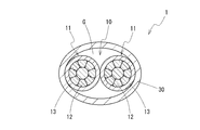
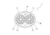
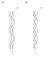
- FIG. 1 is a cross-sectional view showing a communication wire according to an embodiment of the present invention, in which a sheath is provided as a loose jacket. It is sectional drawing which shows the electric wire for communication in which the sheath was provided as a solid jacket. It is a figure explaining two types of twist structures about a twist line, (a) is showing the 1st twist structure (without twist), (b) has shown the 2nd twist structure (with twist). In the figure, a dotted line is a guide which shows the part which falls in the same position centering on the axis of an electric insulated wire along the axis of an electric insulated wire.
- FIG. 1 shows a cross-sectional view of a communication wire 1 according to an embodiment of the present invention.
- the communication wire 1 has a twisted pair wire 10 in which a pair of insulated wires 11 and 11 are twisted together.
- Each insulated wire 11 has a conductor 12 and an insulation coating 13 that covers the outer periphery of the conductor 12.
- the electric wire 1 for communication coats the outer periphery of the whole twisted pair wire 10, and has the sheath 30 which consists of insulating materials.
- the communication wire 1 has a characteristic impedance in the range of 100 ⁇ 10 ⁇ .
- the characteristic impedance of 100 ⁇ 10 ⁇ is a value required for the wire for Ethernet communication.
- the communication wire 1 can be suitably used for high speed communication in an automobile or the like by having such a characteristic impedance.
- the conductor 12 of the insulated wire 11 constituting the twisted pair wire 10 is made of a metal wire having a tensile strength of 400 MPa or more.
- a metal wire As a specific metal wire, a copper alloy wire containing Fe and Ti as described later, and a copper alloy wire containing Fe, P, and Sn can be exemplified.
- the tensile strength of the conductor 12 is more preferably 440 MPa or more, and further preferably 480 MPa or more.
- the conductor 12 Since the conductor 12 has a tensile strength of 400 MPa or more, and further 440 MPa or more, 480 MPa or more, the tensile strength required for the wire can be maintained even if the diameter is reduced.
- the diameter of the conductor 12 By reducing the diameter of the conductor 12, the distance between the two conductors 12 and 12 constituting the twisted pair wire 10 (the distance connecting the centers of the conductors 12 and 12) becomes close, and the characteristic impedance of the communication wire 1 become larger.
- the diameter of the conductor 12 can be reduced to such an extent that the cross-sectional area of the conductor is less than 0.22 mm 2 , and further 0.15 mm 2 or less and 0.13 mm 2 or less.
- the outer diameter of the conductor 12 can be 0.55 mm or less, further 0.50 mm or less, and 0 or 45 mm or less. If the diameter of the conductor 12 is excessively reduced, maintenance of strength becomes difficult and the characteristic impedance of the communication wire 1 becomes too large, so the conductor cross-sectional area is preferably set to 0.08 mm 2 or more.
- the communication wire 1 can be obtained even if the thickness of the insulating coating 13 covering the outer periphery of the conductor 12 is reduced to 0.30 mm or less, for example. In this case, it is easy to secure a characteristic impedance of 100 ⁇ 10 ⁇ . In the case of a conventional general copper wire, it is difficult to use the conductor cross-sectional area as less than 0.22 mm 2 due to the low tensile strength.
- the conductor 12 preferably has a breaking elongation of 7% or more.
- high tensile strength conductors have low toughness and often have low impact resistance when force is applied rapidly.
- the conductor 12 having a high tensile strength of 400 MPa or more has a breaking elongation of 7% or more, the process of assembling the wire harness from the communication wire 1 and the assembly of the wire harness
- the conductor 12 can exhibit high impact resistance even if an impact is applied to the conductor 12 in the process of 3.
- the breaking elongation of the conductor 12 is more preferably 10% or more.
- the conductor 12 may be a single wire, but is preferably a stranded wire in which a plurality of strands are twisted together from the viewpoint of enhancing the flexibility and the like. In this case, after the strands are twisted together, compression molding may be performed to form a compressed stranded wire. By compression molding, the outer diameter of the conductor 12 can be reduced. In addition, when the conductor 12 is formed of a stranded wire, as long as the conductor 12 as a whole has a tensile strength of 400 MPa or more, it may be all the same strand or may be two or more types of strands.
- a strand composed of a copper alloy containing Fe and Ti as described later, or a copper alloy containing Fe and P, Sn, and metals such as SUS and other metals other than copper alloys can be illustrated.
- the insulation coating 13 of the insulated wire 11 may be made of any insulating polymer material. From the viewpoint of securing a predetermined high value as the characteristic impedance, the insulating coating 13 preferably has a relative dielectric constant of 4.0 or less.
- a polymer material polyolefins such as polyethylene and polypropylene, polyvinyl chloride, polystyrene, polytetrafluoroethylene, polyphenylene sulfide and the like can be mentioned.
- the insulated wire 11 may optionally contain an additive such as a flame retardant, in addition to the polymer material.
- the thickness of the insulating coating 13 necessary for securing a predetermined characteristic impedance by the effect of reducing the diameter of the conductor 12 and raising the characteristic impedance by the approach between the conductors 12 and 12 Can be made smaller.
- the thickness of the insulating coating 13 is preferably 0.30 mm or less, more preferably 0.25 mm or less, and 0.20 mm or less. If the thickness of the insulating coating 13 is too thin, it becomes difficult to secure a characteristic impedance of a necessary size, so the thickness of the insulating coating 13 is preferably larger than 0.15 mm.
- the entire diameter of the insulated wire 11 is reduced.
- the outer diameter of the insulated wire 11 can be 1.05 mm or less, further 0.95 mm or less, and 0.85 mm or less.
- the diameter of the insulated wire 11 can be reduced.
- the uniformity of the thickness (insulation thickness) of the insulating coating 13 be high over the entire circumference of the conductor 12. That is, it is preferable that the uneven thickness be small. Then, the eccentricity of the conductor 12 is reduced, and when the twisted pair wire 10 is configured, the symmetry of the position of the conductor 12 in the twisted wire pair 10 is increased. As a result, the transmission characteristics of the communication wire 1, particularly, the mode conversion characteristics can be enhanced.
- the eccentricity ratio of each insulated wire 11 may be 65% or more, more preferably 75% or more.
- the eccentricity factor is calculated as [minimum insulation thickness] / [maximum insulation thickness] ⁇ 100%.
- the twisted wire 10 can be formed by twisting two insulated wires 11, and the twisting pitch can be set according to the outer diameter of the insulated wire 11 and the like. it can. However, by setting the twist pitch to 60 times or less, preferably 45 times or less, and more preferably 30 times or less of the outer diameter of the insulated wire 11, looseness of the twist structure can be effectively suppressed. Looseness of the twist structure can lead to variations in characteristic impedance of the communication wire 1 and various transmission characteristics and to changes with time. In particular, as described later, when the sheath 30 is of a loose jacket type, the presence of the air gap G between the sheath 30 and the twisted pair wire 10 makes the twin twisting more than that of the solid jacket type.
- the twist pitch is preferably at least 8 times the outer diameter of the insulated wire 11, more preferably Is preferably 12 times or more and 15 times or more.
- the following two structures can be illustrated as a twisting structure of the two insulated wires 11 in the twisted pair wire 10.
- the first twisting structure as shown in FIG. 3A, no twisting structure centered on the twisting axis is added to each insulated wire 11, and an insulated wire centered on the axis of the insulated wire 11 itself
- the relative top, bottom, left, and right directions of the 11 parts do not change along the twisting axis. That is, in the whole area of the twisting structure, the portions corresponding to the same position around the axis of the insulated wire 11 always point in the same direction, for example, upward.
- the second twisting structure as shown in FIG. 3B, a twisting structure is added to each insulated wire 11 with the twisting axis as the center, and the axis of the insulated wire 11 itself is the center
- the relative vertical and horizontal directions of each part of the insulated wire 11 change along the twisting axis. That is, in the twisting structure, the direction in which the portions that correspond to the same position centering on the axis of the insulated wire 11 are changed in the vertical and horizontal directions.
- the difference between the lengths of the two insulated wires 11 constituting the twisted pair wire 10 (difference in wire length) be smaller.
- the symmetry of the two insulated wires 11 can be raised, and the transmission characteristics, in particular, the mode conversion characteristics can be improved.
- the wire length difference per 1 m of twisted wire pair is suppressed to 5 mm or less, more preferably 3 mm or less, the influence of the wire length difference can be easily suppressed.
- the sheath 30 is provided for the purpose of protection of the twisted pair wire 10, holding of the twist structure, and the like.
- the sheath 30 is provided as a loose jacket and accommodates the twisted pair 10 in a hollow cylindrically shaped space.
- the sheath 30 is in contact with the insulated wire 11 constituting the twisted pair wire 10 only in a partial region along the circumferential direction of the inner peripheral surface, and in the other region, the sheath 30 and the insulated wire 11 are There is an air gap G between them, and a layer of air is formed. Details of the configuration of the sheath 30 will be described later.
- the sheath by the cutting operation for forming the cross section is embedded in a resin such as an acrylic resin so that the resin does not penetrate into the inner space of the sheath 30 so that deformation of the twisted pair 30 or the twisted wire 10 does not disturb accurate evaluation. It is preferable to perform the cutting operation after fixing in the state. In the cut surface, the area in which the acrylic resin is present is the area originally having the void G.
- a shield made of a conductive material surrounding the twisted pair wire 20 is not provided inside the sheath 30, and The sheath 30 directly surrounds the outer periphery.
- the shield plays a role of shielding noise from the outside and the noise from the outside with respect to the twisted wire pair 10, but the communication wire 1 according to the present embodiment has a condition in which the influence of the noise is not serious. It is assumed to be used in the case and no shield is provided.
- the sheath 30 directly coats the outer periphery of the twisted pair 20 through the air gap G without a member.
- the conductor 12 of the insulated wire 11 constituting the twisted pair wire 10 has a tensile strength of 400 MPa or more. Even if the diameter of the conductor 12 is reduced, it is easy to maintain sufficient strength as a wire for automobile. By reducing the diameter of the conductor 12, the distance between the two conductors 12, 12 constituting the twisted pair wire 10 becomes close. As the distance between the two conductors 12 and 12 decreases, the characteristic impedance of the communication wire 1 increases.
- the layer of the insulation coating 13 of the insulated wire 11 constituting the twisted pair wire 10 becomes thinner, the characteristic impedance becomes smaller, but in the communication wire 1, due to the effect of the approach accompanying the reduction of the diameter of the conductors 12,12, Even if the thickness of the insulating coating 13 is reduced to, for example, 0.30 mm or less, it is possible to secure a characteristic impedance of 100 ⁇ 10 ⁇ in the communication wire 1.
- the wire diameter (finished diameter) of the communication wire 1 as a whole can be reduced.
- the wire diameter of the communication wire 1 can be set to 2.9 mm or less, and further to 2.5 mm or less.
- the communication wire 1 is preferably reduced in diameter while maintaining a predetermined characteristic impedance value, so that the communication wire 1 is suitably used for high-speed communication in a limited space such as an automobile. be able to.
- the reduction in diameter of the conductor 12 and the reduction in thickness of the insulating coating 13 of the insulated wire 11 are effective not only for reducing the diameter of the communication wire 1 but also for reducing the weight of the communication wire 1.
- the weight of the communication wire 1 for example, when the communication wire 1 is used for communication in a car, the weight of the whole vehicle can be reduced, which leads to reduction in fuel consumption of the vehicle.
- the electric wire 1 for communication will have high breaking strength.
- the breaking strength can be 100 N or more, and further 140 N or more.
- the terminal can exhibit high gripping force with respect to the terminal or the like. That is, it becomes easy to prevent breakage of the communication wire 1 at a portion where a terminal or the like is attached to the terminal.
- transmission characteristics other than the characteristic impedance that is, transmission loss (IL), reflection loss (RL), transmission mode It is desirable that transmission characteristics such as conversion (LCTL) and reflection mode conversion (LCL) also satisfy predetermined levels.
- the sheath 30 of the loose jacket type configuration makes the insulation coating 13 of the insulated wire 11 less than 0.25 mm, and even 0.15 mm or less,
- the level of IL ⁇ 0.68 dB / m (66 MHz), RL ⁇ 20.0 dB (20 MHz), LCTL ⁇ 46.0 dB (50 MHz), and LCL ⁇ 46.0 dB (50 MHz) can be satisfied.
- the sheath 30 is provided as a loose jacket, and a gap G is present between the sheath 30 and the insulated wire 11 constituting the twisted pair wire 10.
- the communication wire 1 'of a form which provides sheath 30' as a solid jacket can also be considered.
- the sheath 30 ' is in contact with the insulated wire 11 constituting the twisted pair wire 10 or is formed in a solid state to a position immediately thereabout, and between the sheath 30' and the insulated wire 11
- the voids are substantially absent except for the voids that are inevitably formed.
- the case where the sheath 30 is a loose jacket is more preferable than the case where the sheath 30 is a solid jacket.
- the characteristic impedance of the communication wire 1 is higher when the twisted pair wire 10 is surrounded by a material having a low dielectric constant (see equation (1) below), and a layer of air is present around the twisted wire pair 10
- the configuration of the loose jacket can make the characteristic impedance higher than in the case of the solid jacket in which the dielectric immediately exists on the outside of the twisted pair wire 10.
- the characteristic impedance of 100 ⁇ 10 ⁇ can be secured.
- the diameter of the insulated wire 11 can be reduced, and the outer diameter of the entire communication wire 1 can also be reduced.
- the thickness of the insulating coating 13 of the insulated wire 11 is The characteristic impedance of 100 ⁇ 10 ⁇ can be secured in the communication wire 1 even if it is less than 0.25 mm, and even 0.20 mm or less. In this case, the outer diameter of the entire communication wire 1 can be 2.5 mm or less.
- the weight reduction of the communication wire 1 as a whole It can contribute to low fuel consumption when used in automobiles.
- the sheath 30 of a loose jacket type since the sheath 30 has a hollow cylindrical shape, the communication wire 1 as a whole is easily influenced by an unintended bending or bending, but the tensile strength as the conductor 12 The point can be compensated by using a pressure of 400 MPa or more.
- the effective dielectric constant (see the following formula (1)) is smaller, and the characteristic impedance of the communication wire 1 is larger.
- the ratio of the area occupied by the void G to the area of the entire area surrounded by the outer peripheral edge of the sheath 30, ie, the cross section including the thickness of the sheath 30 If the area ratio is 8% or more, a sufficient air layer will be present around the twisted wire pair 10, and a characteristic impedance of 100 ⁇ 10 ⁇ can be easily secured.
- the outer peripheral area ratio of the air gap G is more preferably 15% or more.
- the outer peripheral area ratio of the gap G is preferably 30% or less, more preferably 23% or less.
- the ratio of the area occupied by the gap G (inner peripheral area ratio) can also be used.
- the inner peripheral area ratio of the air gap G may be 26% or more, more preferably 39% or more.
- the inner circumferential area rate may be suppressed to 56% or less, more preferably 50% or less.
- the thickness of the sheath 30 also affects the effective dielectric constant and the characteristic impedance of the communication wire 1, and therefore, as an index for securing a sufficient characteristic impedance, an air gap with the outer peripheral area ratio as an index rather than the inner peripheral area ratio It is preferable to set G. However, particularly when the sheath 30 is thick, the thickness of the sheath 30 has less influence on the characteristic impedance of the communication wire 1, so the inner circumferential area ratio is also a good index.
- the ratio of the gap G in the cross section may not be constant at each portion within one pitch of the twisted pair wire 10.
- the ratio of the gap G may be evaluated using the volume in the length region of one pitch of the twisted pair wire 10 as an index.
- the ratio of the volume occupied by the air gap G (outer peripheral volume ratio) to the volume of the region surrounded by the outer peripheral surface of the sheath 30 is 7% or more Preferably, it is 14% or more. Further, the outer peripheral volume ratio may be 29% or less, more preferably 22% or less. Alternatively, the ratio of the volume occupied by the air gap G (inner peripheral volume ratio) of the volume of the region surrounded by the inner peripheral surface of the sheath 30 in the length region of one pitch of the twisted wire 10 is 25% or more More preferably, it is 38% or more. Further, the inner peripheral volume ratio may be 55% or less, more preferably 49% or less.
- the effective dielectric constant represented by the following equation 1 is smaller.
- the effective dielectric constant depends not only on the size of the air gap G but also on parameters such as the material and thickness of the sheath 30, but the effective dielectric constant is preferably 7.0 or less, more preferably 6.0 or less, By selecting the size of the air gap G and other parameters, the characteristic impedance of the communication wire 1 can be easily increased to an area of 100 ⁇ 10 ⁇ .
- the effective dielectric constant is preferably 1.5 or more, more preferably 2.0 or more from the viewpoint of the productivity of the communication wire 1 and the reliability of the wire and from the viewpoint of securing a certain thickness of the insulation coating. You should The size of the air gap G can be controlled by the conditions (die / point shape, extrusion temperature, etc.) when forming the sheath 30 by extrusion.
- ⁇ eff is an effective dielectric constant
- d is a conductor diameter
- D is a wire outer diameter
- ⁇ 0 is a constant.
- the sheath 30 is in contact with the insulated wire 11 in a partial region of the inner circumferential surface. In these regions, as long as the sheath 30 is firmly in close contact with the insulated wire 11, the sheath 30 holds down the twisted wire 10, thereby causing displacement of the twisted wire 10 in the inner space of the sheath 30 or twisted wire. It is possible to suppress the phenomenon such as 10 looseness of the twist structure.
- the adhesion of the sheath 30 to the insulated wire 11 is 4 N or more, more preferably 7 N or more and 8 N or more, these phenomena are suppressed, and the distance between the two insulated wires 11 is a small value, for example By maintaining substantially 0 mm, it is possible to effectively suppress variations in characteristic impedance and various transmission characteristics and changes over time.
- the adhesion of the sheath 30 is too large, the processability of the communication wire 1 is deteriorated, so the adhesion may be suppressed to 70 N or less.
- the adhesion of the sheath 30 to the insulated wire 11 can be adjusted by changing the extrusion temperature of the resin material when forming the sheath 30 on the outer periphery of the twisted pair wire 10 by extruding the resin material.
- the adhesion can be evaluated as, for example, the strength until the twisted wire 10 is pulled off by pulling the twisted wire 10 in a state where the sheath 30 is removed 30 mm from one end in the communication wire 1 having a total length of 150 mm.
- the length (contact ratio) of the portion in contact with the insulated wire 11 is 0.5% or more in the cross section substantially perpendicular to the axis of the communication wire 1. If the content is preferably 2.5% or more, those phenomena can be effectively suppressed. On the other hand, if the contact ratio is set to 80% or less, more preferably 50% or less, the gap G can be easily secured.
- the contact ratio preferably satisfies the above condition as an average value of the length region of one pitch of the twisted wire pair 10, and satisfies the above condition over the entire length region of one pitch. And is more preferable.
- the thickness of the sheath 30 may be selected as appropriate.
- the influence of noise from the outside of the communication wire 1 for example, the viewpoint of reducing the influence from other wires when the communication wire 1 is used in the state of a wire harness etc. together with the other wires, and wear resistance
- the thickness of the sheath may be 0.20 mm or more, more preferably 0.30 mm or more.
- the thickness of the sheath 30 may be 1.0 mm or less, more preferably 0.7 mm or less.
- the loose jacket type sheath 30 from the viewpoint of reducing the diameter of the communication wire 1, but as shown in FIG. It is also conceivable to use a solid jacket type sheath 30 '.
- the solid type sheath 30 ' can firmly fix the twisted pair wire 10 by the sheath 30', and it is easy to prevent phenomena such as displacement of the twisted pair wire 10 with respect to the sheath 30 'and looseness of the twist structure. .
- the sheath 30 is a loose-jacket type or a solid-jacket type sheath 30 can be controlled by the conditions (die / point shape, extrusion temperature, etc.) when forming the sheath by extrusion. Further, in a situation where there is no problem in the protection of the twisted pair wire 10 or the holding of the twist structure, the sheath 30 can be omitted, and it is not necessarily provided in the communication wire.
- the sheath 30 as well as the insulation coating 13 of the insulated wire 11 may be made of any polymer material. That is, examples of the polymer material include polyolefins such as polyethylene and polypropylene, polyvinyl chloride, polystyrene, polytetrafluoroethylene, polyphenylene sulfide and the like. Among these, from the viewpoint of increasing the characteristic impedance of the communication wire 1, it is particularly preferable to use a polyolefin which is a nonpolar polymer material.
- the sheath 30 may optionally contain an additive such as a flame retardant, in addition to the polymer material. Although the sheath 30 may be composed of a plurality of layers, it is preferable that the sheath 30 be composed of only one layer from the viewpoint of reducing the diameter and cost of the communication wire 1 by simplifying the configuration.
- the copper alloy wire mentioned as a first example here has the following component composition. Fe: 0.05% by mass or more, 2.0% by mass or less Ti: 0.02% by mass or more, 1.0% by mass or less Mg: 0% by mass or more, 0.6% by mass or less (containing Mg Not included))
- the balance consists of Cu and unavoidable impurities.
- the copper alloy wire having the above composition has very high tensile strength.
- the content of Fe is 0.8% by mass or more, and the content of Ti is 0.2% by mass or more, particularly high tensile strength can be achieved.
- the tensile strength can be increased by increasing the degree of wire drawing and reducing the wire diameter, or by performing heat treatment after wire drawing, and the conductor 11 having a tensile strength of 400 MPa or more can be obtained. .
- the copper alloy wire mentioned as a 2nd example has the following component compositions. Fe: 0.1 mass% or more, 0.8 mass% or less P: 0.03 mass% or more, 0.3 mass% or less Sn: 0.1 mass% or more, 0.4 mass% or less Remainder Is composed of Cu and unavoidable impurities.
- the copper alloy wire having the above composition has very high tensile strength.
- the content of Fe is 0.4% by mass or more and the content of P is 0.1% by mass or more, particularly high tensile strength can be achieved.
- the tensile strength can be increased by increasing the degree of wire drawing and reducing the wire diameter, or by performing heat treatment after wire drawing, and the conductor 11 having a tensile strength of 400 MPa or more can be obtained. .
- the obtained conductor had a conductor cross-sectional area of 0.13 mm 2 and an outer diameter of 0.45 mm.
- the tensile strength and the breaking elongation of the copper alloy conductor thus obtained were evaluated according to JIS Z 2241. At this time, the distance between the marks was 250 mm, and the tensile speed was 50 mm / min. As a result of evaluation, the tensile strength was 490 MPa and the elongation at break was 8%.
- the characteristic impedance of the obtained communication wire was measured. The measurement was performed by the open / short method using an LCR meter.
- samples A1 to A3 using copper alloy conductors and having a conductor cross-sectional area smaller than 0.22 mm 2 are used as conductors and a pure copper wire is used.
- the behavior of the above-mentioned characteristic impedance is interpreted as a result that the diameter of the conductor can be reduced when using a copper alloy wire as the conductor than when using a pure copper wire, and the distance between the conductors is closer. Ru.
- the thickness of the insulation coating can be less than 0.30 mm while maintaining the characteristic impedance of 100 ⁇ 10 ⁇ , and 0.18 mm for the thinnest. It has become possible.
- by thinning the insulation coating it is possible to reduce the finished outer diameter of the communication wire together with the effect of reducing the diameter of the conductor itself.
- characteristic impedances of substantially the same value are obtained for the sample A3 using a copper alloy conductor as the conductor and the sample A6 using a pure copper wire.
- the finished outer diameters of the two are compared, the finished outer diameter of the communication wire is reduced by about 20% in the sample A3 using the copper alloy conductor because the thinning of the conductor can be achieved. There is.
- the characteristic impedance is out of the range of 100 ⁇ 10 ⁇ . That is, the characteristic impedance in the range of 100 ⁇ 10 ⁇ can be obtained by appropriately selecting the thickness of the insulation coating after reducing the diameter of the conductor using a copper alloy.
- a communication wire was produced in the same manner as the samples A1 to A4 in the above-mentioned test [1].
- the eccentricity of the insulated wire was set to 80%, and the twisted structure of the twisted pair was made the first twisted structure (without twist).
- two types of sheaths a loose jacket type as shown in FIG. 1 and a solid jacket type as shown in FIG. 2 were prepared.
- the sheath was made of polypropylene.
- the thickness of the sheath was determined by the die point shape used, and was 0.4 mm for the loose jacket type and 0.5 mm for the thinnest type.
- the size of the air gap between the loose jacket type sheath and the insulated wire was 23% in the outer peripheral area ratio, and the adhesion of the sheath to the insulated wire was 15N. Moreover, several samples which changed the thickness of the insulation coating of the insulated wire about each case were produced.
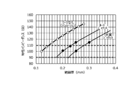
- FIG. 4 shows the insulation thickness and the characteristic impedance obtained by the above equation (1) which is known as the theoretical expression of the characteristic impedance of the communication wire having the twisted pair when no sheath is provided.
- the approximate curve based on Formula (1) is shown also to the measurement result in the case of having each sheath. Further, the broken line in the drawing indicates a range in which the characteristic impedance is 100 ⁇ 10 ⁇ .
- the characteristic impedance in the case where the insulation thickness is the same is lowered corresponding to the increase of the effective dielectric constant.
- the degree of the decrease is smaller in the case of the loose jacket type than in the case of the solid jacket type of the sheath, and a large characteristic impedance is obtained.
- the insulation thickness required to obtain the same characteristic impedance may be smaller.
- the characteristic impedance is 100 ⁇ in the case of the loose jacket type, in the case of the insulation thickness of 0.20 mm, and in the case of the solid jacket type, in the case of the insulation thickness of 0.25 mm.
- the insulation thickness and the outer diameter and mass of the communication wire are summarized in Table 2 below.
- the insulation thickness is reduced by 25%
- the outer diameter of the communication wire is 7.4%
- the mass is reduced by 27%, compared to the solid jacket type. ing. That is, by using the loose jacket type sheath, even if the insulation thickness of the insulated wire constituting the twisted pair is reduced, it is possible to obtain a sufficient characteristic impedance, and as a result, the entire communication wire It has been verified that the outer diameter can be reduced and the mass can be further reduced.
- the size of the void was measured for each of the samples prepared above. Under the present circumstances, after embedding the electric wire for communication of each sample in acrylic resin and fixing, it cut
- the characteristic impedance in the range of 100 ⁇ 10 ⁇ is stably obtained.
- the effective dielectric constant becomes too large due to the small size of the air gap, and the characteristic impedance does not reach 100 ⁇ 10 ⁇ .
- the characteristic impedance exceeds the range of 100 ⁇ 10 ⁇ to the high side.
- the adhesion of the sheath was measured for each of the samples prepared above.
- the adhesion of the sheath was evaluated in a sample with a total length of 150 mm in a state where the sheath was removed 30 mm from one end, the insulated wire was pulled, and the strength until the insulated wire fell off was evaluated.
- changes in characteristic impedance were measured under conditions simulating use over time. Specifically, the communication wire for each sample is bent 200 times at an angle of 90 ° along a mandrel with an outer diameter of 25 mm, and then the characteristic impedance of the bent portion is measured, and the amount of change from before bending is recorded. did.
- the change of the characteristic impedance by the influence of other wires was evaluated. Specifically, first, the characteristic impedance in the state of an independent single wire was measured for the communication wire of each sample. In addition, the characteristic impedance was measured even in a state in which the other electric wires were embraced. Here, in a state in which the other electric wires are embraced, the six other electric wires (PVC electric wire with an outer diameter of 2.6 mm) are arranged in contact with the outer periphery of the sample electric wire at approximately the center of the sample electric wire. What was fixed by winding a PVC tape was prepared. And based on the value of the characteristic impedance in the state of a single wire, the change amount of the characteristic impedance in the state which carried in the other electric wire was recorded.
- Table 6 shows the measurement results of the eccentricity and the mode conversion characteristics. As the value of each mode conversion, the absolute value indicates the minimum value in the range of 1 to 50 MHz.
- Table 7 summarizes the relationship between the twist pitch of the twisted pair and the amount of change in the characteristic impedance.
- the twist pitch of the twisted pair is indicated by a value based on the outer diameter (0.85 mm) of the insulated wire, that is, how many times the outer diameter of the insulated wire is.
- Table 8 shows the relationship between the type of twist structure and the fluctuation range of the characteristic impedance.
- the sheath for covering the outer periphery of the twisted pair wire may be provided not only as a loose jacket type but also as a full type according to the degree of request for reduction in diameter of the communication wire. Moreover, it can also be set as the structure which does not provide a sheath. That is, it has a twisted pair formed by twisting a pair of insulated wires consisting of a conductor having a tensile strength of 400 MPa or more and an insulating coating covering the outer periphery of the conductor, and has a characteristic impedance of 100 ⁇ 10 ⁇ .
- the communication wire can be in the range of In this case, the thickness of the insulation coating, the composition and elongation at break of the conductor, the outer diameter and eccentricity of the insulated wire, the twist structure and twist pitch of the twisted wire, the thickness and adhesion of the sheath, the outside of the insulated wire Preferred configurations applicable to each part of the communication wire, such as diameter and breaking strength, are the same as above.
- it has a twisted pair formed by twisting a pair of insulated wires consisting of a conductor with a tensile strength of 400 MPa or more and an insulating coating covering the outer periphery of the conductor, and has a characteristic impedance of 100 ⁇ 10 ⁇ .
Abstract
Provided is an electric wire for communication for which the diameter is reduced, while ensuring characteristic impedance value of the necessary size. An electric wire for communication 1 has: a twisted pair wire 10 made by twisting together a pair of insulated wires 11,11, comprising a conductor 12 that has a tensile strength of 400 MPa or greater, and an insulating coating 13 for coating the periphery of the conductor 12; and a sheath 30 made of an insulating material for coating the periphery of the twisted pair wire 10. There is a gap G existing between the sheath 30 and the insulated wire 11 constituting a part of the twisted pair wire 10. The electric wire for communication 1 has a characteristic impedance in the range of 100 ±10Ω.
Description
本発明は、通信用電線に関し、さらに詳しくは、自動車等において、高速通信に用いることができる通信用電線に関するものである。
The present invention relates to a communication wire, and more particularly to a communication wire that can be used for high-speed communication in an automobile or the like.
自動車等の分野において高速通信の需要が増している。高速通信に用いられる電線においては、特性インピーダンス等の伝送特性を厳しく管理する必要がある。例えば、イーサーネット通信に用いられる電線においては、特性インピーダンスが100±10Ωになるように管理する必要がある。
The demand for high speed communication is increasing in the field of automobiles and the like. In a wire used for high speed communication, it is necessary to strictly control transmission characteristics such as characteristic impedance. For example, in a wire used for Ethernet communication, it is necessary to manage the characteristic impedance to be 100 ± 10 Ω.
通信用電線の特性インピーダンスは、導体径、絶縁被覆の種類や厚さ等、通信用電線の具体的な構成に依存して定まる。例えば、特許文献1においては、導体と該導体を被覆する絶縁体とを備えた一対の絶縁線心を撚り合わせてなる対撚り線と、該対撚り線を被覆するシールド用の金属箔シールドと、該金属箔シールドに対して導通する接地用電線と、これら全体を被覆するシースとを備え、且つ特性インピーダンス値が100±10Ωとなるように構成した通信用シールド電線が開示されている。ここでは、絶縁線心として、導体径が0.55mmのものが用いられ、導体を被覆する絶縁体の厚さは、0.35~0.45mmとなっている。
The characteristic impedance of the communication wire depends on the specific configuration of the communication wire, such as the diameter of the conductor and the type and thickness of the insulating coating. For example, in Patent Document 1, a twisted pair formed by twisting a pair of insulated wires including a conductor and an insulator covering the conductor, and a metal foil shield for a shield that covers the twisted wire. A communication shield wire is disclosed which comprises a grounding wire conducting to the metal foil shield and a sheath covering the whole of these, and is configured to have a characteristic impedance value of 100 ± 10Ω. Here, as the insulating core, one having a conductor diameter of 0.55 mm is used, and the thickness of the insulator covering the conductor is 0.35 to 0.45 mm.
自動車等に用いる通信用電線においては、細径化に対する需要が大きい。この需要を満足するために、特性インピーダンス等の伝送特性を満たしながら、通信用電線の細径化を図ることが必要となる。対撚線を有する通信用電線を細径化する方法として、対撚線を構成する絶縁電線の絶縁被覆を薄くすることが考えられる。しかし、本発明者の試験によると、特許文献1に記載される通信用電線において、絶縁体の厚さを0.35mmよりも小さくすると、特性インピーダンスが90Ωよりも小さくなり、イーサーネット通信で求められる100±10Ωの範囲を外れてしまう。
In communication wires used for automobiles and the like, the demand for reduction in diameter is large. In order to satisfy this demand, it is necessary to reduce the diameter of the communication wire while satisfying transmission characteristics such as characteristic impedance. As a method of reducing the diameter of the communication wire having the twisted wire, it is conceivable to make the insulating coating of the insulated wire constituting the twisted wire thinner. However, according to the test of the inventor of the present invention, in the communication wire described in Patent Document 1, when the thickness of the insulator is smaller than 0.35 mm, the characteristic impedance becomes smaller than 90 Ω, which is determined by Ethernet communication. Be out of the range of 100 ± 10 Ω.
本発明の課題は、必要な大きさの特性インピーダンス値を確保しながら、細径化された通信用電線を提供することにある。
An object of the present invention is to provide a communication wire having a reduced diameter while securing a characteristic impedance value of a necessary size.
上記課題を解決するため、本発明にかかる通信用電線は、引張強さが400MPa以上である導体と、該導体の外周を被覆する絶縁被覆と、からなる1対の絶縁電線が撚り合わせられた対撚線と、前記対撚線の外周を被覆する絶縁材料よりなるシースと、を有し、前記シースと前記対撚線を構成する前記絶縁電線との間に、空隙が存在するものである。
In order to solve the above problems, in the communication wire according to the present invention, a pair of insulated wires consisting of a conductor having a tensile strength of 400 MPa or more and an insulation coating covering the outer periphery of the conductor is twisted It has a twisted pair wire and a sheath made of an insulating material covering the outer periphery of the twisted pair wire, and there is an air gap between the sheath and the insulated wire constituting the twisted pair wire. .
ここで、前記絶縁電線の導体断面積は、0.22mm2未満であるとよい。また、前記絶縁電線の絶縁被覆の厚さは、0.30mm以下であるとよい。前記絶縁電線の外径は、1.05mm以下であるとよい。前記絶縁電線の導体の破断伸びは、7%以上であるとよい。
Here, the conductor cross-sectional area of the insulated wire may be less than 0.22 mm 2 . The thickness of the insulation coating of the insulated wire is preferably 0.30 mm or less. The outer diameter of the insulated wire may be 1.05 mm or less. The breaking elongation of the conductor of the insulated wire may be 7% or more.
前記通信用電線の軸に交差する断面において、前記シースの外周縁に囲まれた領域の面積のうち、前記空隙が占める面積の割合は、8%以上であるとよい。前記通信用電線の軸に交差する断面において、前記シースの外周縁に囲まれた領域の面積のうち、前記空隙が占める面積の割合は、30%以下であるとよい。前記対撚線における撚りピッチは、前記絶縁電線の外径の45倍以下であるとよい。前記絶縁電線に対する前記シースの密着力は、4N以上であるとよい。
In the cross section intersecting the axis of the communication wire, the ratio of the area occupied by the air gap to the area of the region surrounded by the outer peripheral edge of the sheath is preferably 8% or more. In the cross section intersecting the axis of the communication wire, the ratio of the area occupied by the air gap to the area of the region surrounded by the outer peripheral edge of the sheath is preferably 30% or less. The twist pitch in the twisted pair may be 45 times or less the outer diameter of the insulated wire. The adhesion of the sheath to the insulated wire may be 4N or more.
上記発明にかかる通信用電線においては、対撚線を構成する絶縁電線の導体が400MPa以上の高い引張強さを有しているため、電線として必要な強度を確保しながら、導体径を小さくすることができる。すると、対撚線を構成する2本の導体の間の距離が小さくなることにより、通信用電線の特性インピーダンスを高くすることができる。その結果、通信用電線の細径化のために絶縁電線の絶縁被覆を薄くしても、特性インピーダンスを、100±10Ωの範囲よりも小さくならないように、確保することが可能となる。
In the communication wire according to the invention, since the conductor of the insulated wire constituting the twisted pair has a high tensile strength of 400 MPa or more, the diameter of the conductor is reduced while securing the strength necessary for the wire. be able to. Then, the characteristic impedance of the communication wire can be increased by reducing the distance between the two conductors forming the twisted pair. As a result, even if the thickness of the insulation coating of the insulated wire is reduced to reduce the diameter of the communication wire, the characteristic impedance can be secured so as not to be smaller than the range of 100 ± 10 Ω.
さらに、対撚線の外周を被覆するシースと対撚線を構成する絶縁電線との間に、空隙が存在し、対撚線の周囲に空気の層が存在することで、シースが充実状態で形成される場合と比較して、通信用電線の特性インピーダンスを高くすることができる。よって、絶縁電線の絶縁被覆の厚さを小さくしても、通信用電線の特性インピーダンスとして十分に高い値を維持しやすくなる。絶縁電線の絶縁被覆の厚さを小さくすることができれば、通信用電線全体の外径を小さくすることができる。
Furthermore, an air gap is present between the sheath covering the outer periphery of the twisted wire and the insulated wire constituting the twisted wire, and a layer of air is present around the twisted wire, so that the sheath is in a solid state. The characteristic impedance of the communication wire can be increased compared to the case where it is formed. Therefore, even if the thickness of the insulating coating of the insulated wire is reduced, it is easy to maintain a sufficiently high value as the characteristic impedance of the communication wire. If the thickness of the insulation coating of the insulated wire can be reduced, the outer diameter of the entire communication wire can be reduced.
ここで、絶縁電線の導体断面積が、0.22mm2未満である場合には、対撚線を構成する2本の絶縁電線の間の距離が近くなることの効果によって、特性インピーダンスが高くなるので、必要な特性インピーダンスを維持しながら、絶縁被覆を薄くすることによる通信用電線の細径化が行いやすくなる。また、導体の細さ自体も、通信用電線の細径化に効果を有する。
Here, when the conductor cross-sectional area of the insulated wire is less than 0.22 mm 2 , the characteristic impedance is increased due to the effect that the distance between the two insulated wires constituting the twisted pair becomes close. Therefore, it becomes easy to reduce the diameter of the communication wire by thinning the insulation coating while maintaining the required characteristic impedance. In addition, the thinness of the conductor itself is also effective in reducing the diameter of the communication wire.
また、絶縁電線の絶縁被覆の厚さが、0.30mm以下である場合には、絶縁電線が十分に細径化されることで、通信用電線全体が細径化されやすい。
Moreover, when the thickness of the insulation coating of an insulated wire is 0.30 mm or less, the diameter of the whole communication wire is likely to be reduced by the diameter of the insulated wire being sufficiently reduced.
絶縁電線の外径が、1.05mm以下である場合にも、通信用電線全体を細径化しやすい。
Even when the outer diameter of the insulated wire is 1.05 mm or less, it is easy to reduce the diameter of the entire communication wire.
絶縁電線の導体の破断伸びが、7%以上である場合には、導体の耐衝撃性が高くなり、通信用電線のワイヤーハーネスへの加工時や、ワイヤーハーネスの組み付け時等に導体に印加される衝撃に耐えやすくなる。
When the breaking elongation of the conductor of the insulated wire is 7% or more, the impact resistance of the conductor becomes high, and is applied to the conductor at the time of processing the communication wire to the wire harness, at the time of assembling the wire harness, etc. Be more resistant to shocks.
通信用電線の軸に交差する断面において、シースの外周縁に囲まれた領域の面積のうち、空隙が占める面積の割合が、8%以上である場合には、通信用電線の特性インピーダンスを高めることで、通信用電線の外径を小さくする効果に特に優れる。
In the cross section intersecting the axis of the communication wire, if the ratio of the area occupied by the air gap is 8% or more of the area of the region surrounded by the outer peripheral edge of the sheath, the characteristic impedance of the communication wire is increased. This is particularly excellent in the effect of reducing the outer diameter of the communication wire.
通信用電線の軸に交差する断面において、シースの外周縁に囲まれた領域の面積のうち、空隙が占める面積の割合が、30%以下である場合には、空隙が大きすぎることにより、シースの内部空間の中で対撚線の位置が定まらずに、通信用電線の特性インピーダンスや各種伝送特性にばらつきや経時変化が生じるのを防止しやすくなる。
In the cross section intersecting the axis of the communication wire, if the ratio of the area occupied by the void to the area of the region surrounded by the outer peripheral edge of the sheath is 30% or less, the sheath is too large. In the internal space of the above, the position of the twisted pair is not determined, and it is easy to prevent the occurrence of variations or changes with time in the characteristic impedance and various transmission characteristics of the communication wire.
対撚線における撚りピッチが、絶縁電線の外径の45倍以下である場合には、対撚線の撚り構造の緩みが起こりにくくなり、撚り構造の緩みによって、通信用電線の特性インピーダンスや各種伝送特性にばらつきや経時変化が生じるのを防止しやすくなる。
When the twist pitch in the twisted wire is 45 times or less of the outer diameter of the insulated wire, loosening of the twisted structure of the twisted wire is less likely to occur, and the looseness of the twisted structure It becomes easy to prevent the occurrence of variations or time-lapse changes in the transmission characteristics.
絶縁電線に対するシースの密着力が、4N以上である場合には、シースに対する対撚線の位置のずれや対撚線の撚り構造の緩みが起こるのが防止され、それらの影響によって、通信用電線の特性インピーダンスや各種伝送特性にばらつきや経時変化が生じるのを防止しやすくなる。
When the adhesion of the sheath to the insulated wire is 4 N or more, it is possible to prevent the displacement of the position of the twisted wire relative to the sheath and the loosening of the twisted structure of the twisted wire, and by these effects, the communication wire It becomes easy to prevent the occurrence of variations or time-dependent changes in the characteristic impedance of the sensor and various transmission characteristics.
以下、図面を用いて本発明の一実施形態にかかる通信用電線について詳細に説明する。
Hereinafter, the communication wire according to an embodiment of the present invention will be described in detail using the drawings.
[通信用電線の構成]
図1に、本発明の一実施形態にかかる通信用電線1の断面図を示す。 [Composition of communication wire]
FIG. 1 shows a cross-sectional view of acommunication wire 1 according to an embodiment of the present invention.
図1に、本発明の一実施形態にかかる通信用電線1の断面図を示す。 [Composition of communication wire]
FIG. 1 shows a cross-sectional view of a
通信用電線1は、1対の絶縁電線11,11を撚り合わせた対撚線10を有している。各絶縁電線11は、導体12と、導体12の外周を被覆する絶縁被覆13を有している。そして、通信用電線1は、対撚線10全体の外周を被覆して、絶縁材料よりなるシース30を有している。
The communication wire 1 has a twisted pair wire 10 in which a pair of insulated wires 11 and 11 are twisted together. Each insulated wire 11 has a conductor 12 and an insulation coating 13 that covers the outer periphery of the conductor 12. And the electric wire 1 for communication coats the outer periphery of the whole twisted pair wire 10, and has the sheath 30 which consists of insulating materials.
通信用電線1は、100±10Ωの範囲の特性インピーダンスを有している。100±10Ωとの特性インピーダンスは、イーサーネット通信用の電線に求められる値である。通信用電線1は、このような特性インピーダンスを有することで、自動車等において、高速通信用に好適に用いることができる。
The communication wire 1 has a characteristic impedance in the range of 100 ± 10 Ω. The characteristic impedance of 100 ± 10 Ω is a value required for the wire for Ethernet communication. The communication wire 1 can be suitably used for high speed communication in an automobile or the like by having such a characteristic impedance.
(1)絶縁電線の構成
対撚線10を構成する絶縁電線11の導体12は、400MPa以上の引張強さを有する金属線材よりなっている。具体的な金属線材として、後に説明するようなFeおよびTiを含有する銅合金線、また、FeおよびP、Snを含有する銅合金線を例示することができる。導体12の引張強さは、440MPa以上、さらには480MPa以上であれば、より好ましい。 (1) Configuration of Insulated Wire Theconductor 12 of the insulated wire 11 constituting the twisted pair wire 10 is made of a metal wire having a tensile strength of 400 MPa or more. As a specific metal wire, a copper alloy wire containing Fe and Ti as described later, and a copper alloy wire containing Fe, P, and Sn can be exemplified. The tensile strength of the conductor 12 is more preferably 440 MPa or more, and further preferably 480 MPa or more.
対撚線10を構成する絶縁電線11の導体12は、400MPa以上の引張強さを有する金属線材よりなっている。具体的な金属線材として、後に説明するようなFeおよびTiを含有する銅合金線、また、FeおよびP、Snを含有する銅合金線を例示することができる。導体12の引張強さは、440MPa以上、さらには480MPa以上であれば、より好ましい。 (1) Configuration of Insulated Wire The
導体12が、400MPa以上、さらには440MPa以上、480MPa以上の引張強さを有していることで、細径化しても、電線として求められる引張強さを維持することができる。導体12を細径化することで、対撚線10を構成する2本の導体12,12の間の距離(導体12,12の中心を結ぶ距離)が近くなり、通信用電線1の特性インピーダンスが大きくなる。例えば、導体断面積が、0.22mm2未満、さらには0.15mm2以下、0.13mm2以下となる程度まで、導体12を細径化することができる。導体12の外径としては、0.55mm以下、さらには0.50mm以下、0,45mm以下とすることができる。なお、導体12を過度に細径化すると、強度の維持が困難になるとともに、通信用電線1の特性インピーダンスが大きくなりすぎるので、導体断面積は、0.08mm2以上としておくことが好ましい。
Since the conductor 12 has a tensile strength of 400 MPa or more, and further 440 MPa or more, 480 MPa or more, the tensile strength required for the wire can be maintained even if the diameter is reduced. By reducing the diameter of the conductor 12, the distance between the two conductors 12 and 12 constituting the twisted pair wire 10 (the distance connecting the centers of the conductors 12 and 12) becomes close, and the characteristic impedance of the communication wire 1 Becomes larger. For example, the diameter of the conductor 12 can be reduced to such an extent that the cross-sectional area of the conductor is less than 0.22 mm 2 , and further 0.15 mm 2 or less and 0.13 mm 2 or less. The outer diameter of the conductor 12 can be 0.55 mm or less, further 0.50 mm or less, and 0 or 45 mm or less. If the diameter of the conductor 12 is excessively reduced, maintenance of strength becomes difficult and the characteristic impedance of the communication wire 1 becomes too large, so the conductor cross-sectional area is preferably set to 0.08 mm 2 or more.
導体12が0.22mm2未満の小さな導体断面積を有する場合に、導体12の外周を被覆する絶縁被覆13の厚さを、例えば0.30mm以下のように薄くしても、通信用電線1において、100±10Ωの特性インピーダンスを確保しやすくなる。なお、従来一般の銅電線の場合には、引張強さが低いことにより、導体断面積を0.22mm2未満として用いることは困難である。
In the case where the conductor 12 has a small conductor cross-sectional area of less than 0.22 mm 2 , the communication wire 1 can be obtained even if the thickness of the insulating coating 13 covering the outer periphery of the conductor 12 is reduced to 0.30 mm or less, for example. In this case, it is easy to secure a characteristic impedance of 100 ± 10 Ω. In the case of a conventional general copper wire, it is difficult to use the conductor cross-sectional area as less than 0.22 mm 2 due to the low tensile strength.
導体12は、7%以上の破断伸びを有していることが好ましい。一般的に、引張強さの高い導体は、靱性が低く、急激に力が加わった際の耐衝撃性が低いことが多い。しかし、上記のように、400MPa以上の高い引張強さを有する導体12において、7%以上の破断伸びを有していれば、通信用電線1からワイヤーハーネスを組み立てる工程、またそのワイヤーハーネスの組み付けの工程において、導体12に対して衝撃が加えられても、導体12が、高い耐衝撃性を発揮することができる。導体12の破断伸びは、10%以上であれば、さらに好ましい。
The conductor 12 preferably has a breaking elongation of 7% or more. Generally, high tensile strength conductors have low toughness and often have low impact resistance when force is applied rapidly. However, as described above, if the conductor 12 having a high tensile strength of 400 MPa or more has a breaking elongation of 7% or more, the process of assembling the wire harness from the communication wire 1 and the assembly of the wire harness The conductor 12 can exhibit high impact resistance even if an impact is applied to the conductor 12 in the process of 3. The breaking elongation of the conductor 12 is more preferably 10% or more.
導体12は、単線よりなってもよいが、屈曲性を高める等の観点から、複数の素線が撚り合わせられた撚線よりなることが好ましい。この場合に、素線を撚り合わせた後に、圧縮成形を行い、圧縮撚線としてもよい。圧縮成形により、導体12の外径を縮小することができる。また、導体12が撚線よりなる場合に、導体12全体として400MPa以上の引張強さを有していれば、全て同じ素線よりなっても、2種以上の素線よりなってもよい。2種以上の素線を用いる形態として、後に説明するようなFeおよびTiを含有する銅合金、またはFeおよびP、Snを含有する銅合金よりなる素線と、SUS等、銅合金以外の金属材料よりなる素線を用いる場合を例示することができる。
The conductor 12 may be a single wire, but is preferably a stranded wire in which a plurality of strands are twisted together from the viewpoint of enhancing the flexibility and the like. In this case, after the strands are twisted together, compression molding may be performed to form a compressed stranded wire. By compression molding, the outer diameter of the conductor 12 can be reduced. In addition, when the conductor 12 is formed of a stranded wire, as long as the conductor 12 as a whole has a tensile strength of 400 MPa or more, it may be all the same strand or may be two or more types of strands. As a form using 2 or more types of strands, a strand composed of a copper alloy containing Fe and Ti as described later, or a copper alloy containing Fe and P, Sn, and metals such as SUS and other metals other than copper alloys The case where the strand which consists of materials is used can be illustrated.
絶縁電線11の絶縁被覆13は、どのような絶縁性のポリマー材料よりなってもよい。特性インピーダンスとして所定の高い値を確保する観点から、絶縁被覆13は、4.0以下の比誘電率を有することが好ましい。そのようなポリマー材料として、ポリエチレン、ポリプロピレン等のポリオレフィン、ポリ塩化ビニル、ポリスチレン、ポリテトラフルオロエチレン、ポリフェニレンサルファイド等を挙げることができる。絶縁電線11は、ポリマー材料に加え、適宜、難燃剤等の添加剤を含有してもよい。
The insulation coating 13 of the insulated wire 11 may be made of any insulating polymer material. From the viewpoint of securing a predetermined high value as the characteristic impedance, the insulating coating 13 preferably has a relative dielectric constant of 4.0 or less. As such a polymer material, polyolefins such as polyethylene and polypropylene, polyvinyl chloride, polystyrene, polytetrafluoroethylene, polyphenylene sulfide and the like can be mentioned. The insulated wire 11 may optionally contain an additive such as a flame retardant, in addition to the polymer material.
通信用電線1において、導体12を細径化し、導体12,12間の接近によって特性インピーダンスを上昇させていることの効果により、所定の特性インピーダンスを確保するために必要な絶縁被覆13の厚さを小さくすることができる。例えば、絶縁被覆13の厚さを、0.30mm以下、さらには0.25mm以下、0.20mm以下とすることが好ましい。なお、絶縁被覆13を薄くしすぎると、必要な大きさの特性インピーダンスを確保することが難しくなるので、絶縁被覆13の厚さは、0.15mmより大きくしておくことが好ましい。
In the communication wire 1, the thickness of the insulating coating 13 necessary for securing a predetermined characteristic impedance by the effect of reducing the diameter of the conductor 12 and raising the characteristic impedance by the approach between the conductors 12 and 12 Can be made smaller. For example, the thickness of the insulating coating 13 is preferably 0.30 mm or less, more preferably 0.25 mm or less, and 0.20 mm or less. If the thickness of the insulating coating 13 is too thin, it becomes difficult to secure a characteristic impedance of a necessary size, so the thickness of the insulating coating 13 is preferably larger than 0.15 mm.
導体12の細径化および絶縁被覆13の薄層化により、絶縁電線11全体が細径化される。例えば、絶縁電線11の外径を、1.05mm以下、さらには0.95mm以下、そして0.85mm以下とすることができる。絶縁電線11を細径化することで、通信用電線1全体を細径化することができる。
By reducing the diameter of the conductor 12 and thinning the insulating coating 13, the entire diameter of the insulated wire 11 is reduced. For example, the outer diameter of the insulated wire 11 can be 1.05 mm or less, further 0.95 mm or less, and 0.85 mm or less. By reducing the diameter of the insulated wire 11, the entire diameter of the communication wire 1 can be reduced.
絶縁電線11において、導体12の全周にわたって、絶縁被覆13の厚さ(絶縁厚)の均一性が高い方が好ましい。つまり、偏肉が小さいことが好ましい。すると、導体12の偏芯が小さくなり、対撚線10を構成した際に、対撚線10に占める導体12の位置の対称性が高くなる。その結果、通信用電線1の伝送特性、特に、モード変換特性を高めることができる。例えば、各絶縁電線11の偏芯率を、65%以上、より好ましくは75%以上とするとよい。ここで、偏芯率は、[最小絶縁厚]/[最大絶縁厚]×100%として算出される。
In the insulated wire 11, it is preferable that the uniformity of the thickness (insulation thickness) of the insulating coating 13 be high over the entire circumference of the conductor 12. That is, it is preferable that the uneven thickness be small. Then, the eccentricity of the conductor 12 is reduced, and when the twisted pair wire 10 is configured, the symmetry of the position of the conductor 12 in the twisted wire pair 10 is increased. As a result, the transmission characteristics of the communication wire 1, particularly, the mode conversion characteristics can be enhanced. For example, the eccentricity ratio of each insulated wire 11 may be 65% or more, more preferably 75% or more. Here, the eccentricity factor is calculated as [minimum insulation thickness] / [maximum insulation thickness] × 100%.
(2)対撚線の撚り構造
対撚線10は、2本の絶縁電線11を撚り合わせることで形成することができ、撚りピッチは、絶縁電線11の外径等に応じて設定することができる。しかし、撚りピッチを、絶縁電線11の外径の60倍以下、好ましくは45倍以下、さらに好ましくは30倍以下としておくことで、撚り構造の緩みを効果的に抑制することができる。撚り構造の緩みは、通信用電線1の特性インピーダンスや各種伝送特性のばらつきや経時変化につながりうる。特に、後述するように、シース30をルーズジャケット型とする場合に、シース30と対撚線10との間に空隙Gが存在することにより、充実ジャケット型とする場合と比較して、対撚線10において撚り構造を緩ませるような力が働いた際に、シース30によってそれを抑制することが難しい場合があるが、上記のような撚りピッチを選択することで、ルーズジャケット型のシース30を用いる場合にも、撚り構造の緩みを効果的に抑制することができる。撚り構造の緩みを抑制することで、対撚線10を構成する2本の絶縁電線11の間の距離(線間距離)を、ピッチ内の各部位において、小さな値、例えば実質的に0mmに維持し、安定な伝送特性を得ることが可能となる。一方、対撚線10の撚りピッチを小さくしすぎると、対撚線10の生産性が低くなり、製造コストが上昇するため、撚りピッチは、絶縁電線11の外径の8倍以上、さらに好ましくは12倍以上、15倍以上としておくことが好ましい。 (2) Twisted structure of twisted wire pair The twistedwire 10 can be formed by twisting two insulated wires 11, and the twisting pitch can be set according to the outer diameter of the insulated wire 11 and the like. it can. However, by setting the twist pitch to 60 times or less, preferably 45 times or less, and more preferably 30 times or less of the outer diameter of the insulated wire 11, looseness of the twist structure can be effectively suppressed. Looseness of the twist structure can lead to variations in characteristic impedance of the communication wire 1 and various transmission characteristics and to changes with time. In particular, as described later, when the sheath 30 is of a loose jacket type, the presence of the air gap G between the sheath 30 and the twisted pair wire 10 makes the twin twisting more than that of the solid jacket type. When a force acts on the wire 10 so as to loosen the twist structure, it may be difficult to suppress it by the sheath 30. However, by selecting the twist pitch as described above, the loose jacket type sheath 30 is used. Also in the case of using, it is possible to effectively suppress the loosening of the twist structure. By suppressing the loosening of the twisted structure, the distance (inter-line distance) between the two insulated wires 11 constituting the twisted pair wire 10 is set to a small value, for example, substantially 0 mm at each portion in the pitch. It is possible to maintain and obtain stable transmission characteristics. On the other hand, if the twist pitch of the twisted pair wire 10 is too small, the productivity of the twisted pair wire 10 is lowered and the manufacturing cost is increased. Therefore, the twist pitch is preferably at least 8 times the outer diameter of the insulated wire 11, more preferably Is preferably 12 times or more and 15 times or more.
対撚線10は、2本の絶縁電線11を撚り合わせることで形成することができ、撚りピッチは、絶縁電線11の外径等に応じて設定することができる。しかし、撚りピッチを、絶縁電線11の外径の60倍以下、好ましくは45倍以下、さらに好ましくは30倍以下としておくことで、撚り構造の緩みを効果的に抑制することができる。撚り構造の緩みは、通信用電線1の特性インピーダンスや各種伝送特性のばらつきや経時変化につながりうる。特に、後述するように、シース30をルーズジャケット型とする場合に、シース30と対撚線10との間に空隙Gが存在することにより、充実ジャケット型とする場合と比較して、対撚線10において撚り構造を緩ませるような力が働いた際に、シース30によってそれを抑制することが難しい場合があるが、上記のような撚りピッチを選択することで、ルーズジャケット型のシース30を用いる場合にも、撚り構造の緩みを効果的に抑制することができる。撚り構造の緩みを抑制することで、対撚線10を構成する2本の絶縁電線11の間の距離(線間距離)を、ピッチ内の各部位において、小さな値、例えば実質的に0mmに維持し、安定な伝送特性を得ることが可能となる。一方、対撚線10の撚りピッチを小さくしすぎると、対撚線10の生産性が低くなり、製造コストが上昇するため、撚りピッチは、絶縁電線11の外径の8倍以上、さらに好ましくは12倍以上、15倍以上としておくことが好ましい。 (2) Twisted structure of twisted wire pair The twisted
対撚線10において、2本の絶縁電線11の撚り構造として、以下の2つの構造を例示することができる。第一の撚り構造においては、図3(a)に示すように、各絶縁電線11に、撚り合わせ軸を中心とした捻り構造が加えらず、絶縁電線11自体の軸を中心とした絶縁電線11の各部の相対的な上下左右の方向が、撚り合わせ軸に沿って変化しない。つまり、絶縁電線11の軸を中心として同じ位置に当たる部位が、撚り構造の全域において、常に、例えば上方等、同じ方向を向いている。図中で、絶縁電線11の軸を中心として同じ位置に当たる部位を、絶縁電線11の軸に沿って点線で示しているが、捻り構造が加えられていないことに対応して、この点線が、常に紙面手前の中心に見えている。なお、図3(a),(b)では、見やすいように、対撚線10の撚り構造を緩めた状態で表示している。
The following two structures can be illustrated as a twisting structure of the two insulated wires 11 in the twisted pair wire 10. In the first twisting structure, as shown in FIG. 3A, no twisting structure centered on the twisting axis is added to each insulated wire 11, and an insulated wire centered on the axis of the insulated wire 11 itself The relative top, bottom, left, and right directions of the 11 parts do not change along the twisting axis. That is, in the whole area of the twisting structure, the portions corresponding to the same position around the axis of the insulated wire 11 always point in the same direction, for example, upward. In the figure, the portions corresponding to the same position with the axis of the insulated wire 11 at the same position are shown by dotted lines along the axis of the insulated wire 11, but the dotted line corresponds to the absence of the twist structure. It is always visible at the center of the paper. In addition, in FIG. 3 (a), (b), it has displayed in the state which loosened the twist structure of the twisted pair wire 10 so that it may be legible.
一方、第二の撚り構造においては、図3(b)に示すように、各絶縁電線11に、撚り合わせ軸を中心として捻り構造が加えられており、絶縁電線11自体の軸を中心とした絶縁電線11の各部の相対的な上下左右の方向が、撚り合わせ軸に沿って、変化している。つまり、絶縁電線11の軸を中心として同じ位置に当たる部位が、撚り構造の中で、向く方向を上下左右に変化させている。図中で、絶縁電線11の軸を中心として同じ位置に当たる部位を、絶縁電線11の軸に沿って点線で示しているが、捻り構造が加えられていることに対応して、この点線が、撚り構造の1ピッチ内の一部の領域でしか紙面手前に見えておらず、撚り構造の1ピッチ内で紙面に対して前後にその位置を連続的に変化させている。
On the other hand, in the second twisting structure, as shown in FIG. 3B, a twisting structure is added to each insulated wire 11 with the twisting axis as the center, and the axis of the insulated wire 11 itself is the center The relative vertical and horizontal directions of each part of the insulated wire 11 change along the twisting axis. That is, in the twisting structure, the direction in which the portions that correspond to the same position centering on the axis of the insulated wire 11 are changed in the vertical and horizontal directions. In the drawing, the portions corresponding to the same position with the axis of the insulated wire 11 at the same position are shown by dotted lines along the axis of the insulated wire 11, but corresponding to the twist structure being added, this dotted line Only part of the area within one pitch of the twist structure appears in front of the paper, and the position is continuously changed back and forth with respect to the paper within one pitch of the twist structure.
上記2つの撚り構造のうち、第一の撚り構造を採用することが好ましい。第一の撚り構造の方が、撚り構造の1ピッチ内で、2本の絶縁電線11の線間距離の変化が小さいからである。特に、本実施形態にかかる通信用電線1においては、絶縁電線11を細径化していることに起因し、捻りの影響で、線間距離が変化しやすいが、第一の撚り構造を採用することで、その影響を小さく抑えることができる。線間距離が変化すると、通信用電線1の伝送特性が不安定化しやすくなる。
It is preferable to employ | adopt the 1st twist structure among the said 2 twist structures. This is because the change in the distance between the two insulated wires 11 is smaller in the first twist structure within one pitch of the twist structure. In particular, in the communication wire 1 according to the present embodiment, the distance between the wires is likely to change due to the influence of the twist due to the reduction of the diameter of the insulated wire 11, but the first twist structure is adopted. The effect can be kept small. When the distance between the lines changes, the transmission characteristics of the communication wire 1 are easily destabilized.
対撚線10を構成する2本の絶縁電線11の長さの差(線長差)は、小さい方が好ましい。対撚線10において、2本の絶縁電線11の対称性を上げることができ、伝送特性、特にモード変換特性を高めることができる。例えば、対撚線1mあたりの線長差を、5mm以下、さらに好ましくは3mm以下に抑えておけば、線長差の影響を小さく抑えやすい。
It is preferable that the difference between the lengths of the two insulated wires 11 constituting the twisted pair wire 10 (difference in wire length) be smaller. In the twisted pair wire 10, the symmetry of the two insulated wires 11 can be raised, and the transmission characteristics, in particular, the mode conversion characteristics can be improved. For example, if the wire length difference per 1 m of twisted wire pair is suppressed to 5 mm or less, more preferably 3 mm or less, the influence of the wire length difference can be easily suppressed.
(3)シースの概略
シース30は、対撚線10の保護や撚り構造の保持等を目的として設けられるものである。図1の実施形態においては、シース30は、ルーズジャケットとして設けられており、中空筒状に成形された空間の中に、対撚線10を収容している。シース30は、対撚線10を構成する絶縁電線11と、内周面の周方向に沿って一部の領域でのみ接触しており、それ以外の領域においては、シース30と絶縁電線11の間に、空隙Gが存在し、空気の層が形成されている。シース30の構成の詳細については、後述する。 (3) Outline of Sheath Thesheath 30 is provided for the purpose of protection of the twisted pair wire 10, holding of the twist structure, and the like. In the embodiment of FIG. 1, the sheath 30 is provided as a loose jacket and accommodates the twisted pair 10 in a hollow cylindrically shaped space. The sheath 30 is in contact with the insulated wire 11 constituting the twisted pair wire 10 only in a partial region along the circumferential direction of the inner peripheral surface, and in the other region, the sheath 30 and the insulated wire 11 are There is an air gap G between them, and a layer of air is formed. Details of the configuration of the sheath 30 will be described later.
シース30は、対撚線10の保護や撚り構造の保持等を目的として設けられるものである。図1の実施形態においては、シース30は、ルーズジャケットとして設けられており、中空筒状に成形された空間の中に、対撚線10を収容している。シース30は、対撚線10を構成する絶縁電線11と、内周面の周方向に沿って一部の領域でのみ接触しており、それ以外の領域においては、シース30と絶縁電線11の間に、空隙Gが存在し、空気の層が形成されている。シース30の構成の詳細については、後述する。 (3) Outline of Sheath The
なお、シース30と絶縁電線11の間における空隙Gの有無、および後述するような空隙Gの割合等、通信用電線1の断面の状態を評価するに際し、断面を形成するための切断操作によってシース30や対撚線10が変形して正確な評価を妨げることがないように、通信用電線1全体をアクリル等の樹脂に包埋し、シース30の内部の空間にまでその樹脂を浸透させた状態で固定してから、切断操作を行うことが好ましい。切断面において、アクリル樹脂が存在している領域が、本来、空隙Gであった領域である。
In addition, when evaluating the state of the cross section of the communication wire 1 such as the presence or absence of the gap G between the sheath 30 and the insulated wire 11 and the ratio of the gap G as described later, the sheath by the cutting operation for forming the cross section The entire communication wire 1 is embedded in a resin such as an acrylic resin so that the resin does not penetrate into the inner space of the sheath 30 so that deformation of the twisted pair 30 or the twisted wire 10 does not disturb accurate evaluation. It is preferable to perform the cutting operation after fixing in the state. In the cut surface, the area in which the acrylic resin is present is the area originally having the void G.
本実施形態にかかる通信用電線1においては、特許文献1の場合とは異なり、シース30の内側に、対撚線20を包囲する導電性材料よりなるシールドは設けられず、対撚線10の外周を直接シース30が包囲している。シールドは、対撚線10に対して、外部からのノイズの侵入および外部へのノイズの放出を遮蔽する役割を果たすが、本実施形態にかかる通信用電線1は、ノイズの影響が深刻でない条件で使用することを想定しており、シールドを設けていない。本実施形態にかかる通信用電線1においては、構成の簡素化による細径化と低コスト化を効果的に達成する観点から、シース30と対撚線20の間に、シールド以外にも他の部材を有さず、シース30が、空隙Gを介して、対撚線20の外周を直接被覆するものであることが好ましい。
Unlike the case of Patent Document 1, in the communication electric wire 1 according to the present embodiment, a shield made of a conductive material surrounding the twisted pair wire 20 is not provided inside the sheath 30, and The sheath 30 directly surrounds the outer periphery. The shield plays a role of shielding noise from the outside and the noise from the outside with respect to the twisted wire pair 10, but the communication wire 1 according to the present embodiment has a condition in which the influence of the noise is not serious. It is assumed to be used in the case and no shield is provided. In the communication wire 1 according to the present embodiment, from the viewpoint of effectively achieving reduction in diameter and cost reduction due to the simplification of the configuration, there are other than the shield between the sheath 30 and the twisted wire pair 20. It is preferable that the sheath 30 directly coats the outer periphery of the twisted pair 20 through the air gap G without a member.
(4)通信用電線全体の特性
以上のように、本通信用電線1においては、対撚線10を構成する絶縁電線11の導体12が、400MPa以上の引張強さを有していることにより、導体12を細径化しても、自動車用電線として十分な強度を維持しやすくなっている。導体12を細径化することで、対撚線10を構成する2本の導体12,12の間の距離が近くなる。2本の導体12,12の間の距離が近くなると、通信用電線1の特性インピーダンスが高くなる。対撚線10を構成する絶縁電線11の絶縁被覆13の層が薄くなると、特性インピーダンスが小さくなるが、本通信用電線1においては、導体12,12の細径化に伴う接近の効果により、絶縁被覆13の厚さを、例えば0.30mm以下のように小さくしても、通信用電線1において、100±10Ωという特性インピーダンスを確保することが可能となっている。 (4) Characteristics of Entire Communication Wire As described above, in thepresent communication wire 1, the conductor 12 of the insulated wire 11 constituting the twisted pair wire 10 has a tensile strength of 400 MPa or more. Even if the diameter of the conductor 12 is reduced, it is easy to maintain sufficient strength as a wire for automobile. By reducing the diameter of the conductor 12, the distance between the two conductors 12, 12 constituting the twisted pair wire 10 becomes close. As the distance between the two conductors 12 and 12 decreases, the characteristic impedance of the communication wire 1 increases. If the layer of the insulation coating 13 of the insulated wire 11 constituting the twisted pair wire 10 becomes thinner, the characteristic impedance becomes smaller, but in the communication wire 1, due to the effect of the approach accompanying the reduction of the diameter of the conductors 12,12, Even if the thickness of the insulating coating 13 is reduced to, for example, 0.30 mm or less, it is possible to secure a characteristic impedance of 100 ± 10 Ω in the communication wire 1.
以上のように、本通信用電線1においては、対撚線10を構成する絶縁電線11の導体12が、400MPa以上の引張強さを有していることにより、導体12を細径化しても、自動車用電線として十分な強度を維持しやすくなっている。導体12を細径化することで、対撚線10を構成する2本の導体12,12の間の距離が近くなる。2本の導体12,12の間の距離が近くなると、通信用電線1の特性インピーダンスが高くなる。対撚線10を構成する絶縁電線11の絶縁被覆13の層が薄くなると、特性インピーダンスが小さくなるが、本通信用電線1においては、導体12,12の細径化に伴う接近の効果により、絶縁被覆13の厚さを、例えば0.30mm以下のように小さくしても、通信用電線1において、100±10Ωという特性インピーダンスを確保することが可能となっている。 (4) Characteristics of Entire Communication Wire As described above, in the
絶縁電線11の絶縁被覆13を薄くすることで、通信用電線1全体としての線径(仕上がり径)を細くすることができる。例えば、通信用電線1の線径を、2.9mm以下、さらには2.5mm以下とすることができる。通信用電線1が、所定の特性インピーダンス値を保ちながら、細径化されることで、通信用電線1を、自動車内等、空間が限られた場所での高速通信の用途に、好適に用いることができる。
By thinning the insulation coating 13 of the insulated wire 11, the wire diameter (finished diameter) of the communication wire 1 as a whole can be reduced. For example, the wire diameter of the communication wire 1 can be set to 2.9 mm or less, and further to 2.5 mm or less. The communication wire 1 is preferably reduced in diameter while maintaining a predetermined characteristic impedance value, so that the communication wire 1 is suitably used for high-speed communication in a limited space such as an automobile. be able to.
絶縁電線11を構成する導体12の細径化および絶縁被覆13の薄肉化は、通信用電線1の細径化のみならず、通信用電線1の軽量化にも効果を有する。通信用電線1を軽量化することで、例えば通信用電線1を自動車内の通信に用いた際に、車両全体を軽量化することができ、車両の低燃費化につながる。
The reduction in diameter of the conductor 12 and the reduction in thickness of the insulating coating 13 of the insulated wire 11 are effective not only for reducing the diameter of the communication wire 1 but also for reducing the weight of the communication wire 1. By reducing the weight of the communication wire 1, for example, when the communication wire 1 is used for communication in a car, the weight of the whole vehicle can be reduced, which leads to reduction in fuel consumption of the vehicle.
また、絶縁電線11を構成する導体12が、400MPa以上の引張強さを有していることで、通信用電線1が、高い破断強度を有するものとなる。例えば、破断強度を、100N以上、さらには140N以上とすることができる。通信用電線1が、高い破断強度を有することで、端末において、端子等に対して高い把持力を示すことができる。つまり、端末に端子等を取り付けた部位における通信用電線1の破断を防止しやすくなる。
Moreover, when the conductor 12 which comprises the insulated wire 11 has tensile strength of 400 Mpa or more, the electric wire 1 for communication will have high breaking strength. For example, the breaking strength can be 100 N or more, and further 140 N or more. By the communication wire 1 having high breaking strength, the terminal can exhibit high gripping force with respect to the terminal or the like. That is, it becomes easy to prevent breakage of the communication wire 1 at a portion where a terminal or the like is attached to the terminal.
さらに、通信用電線においては、100±10Ωのような十分な大きさの特性インピーダンスを有することに加え、特性インピーダンス以外の伝送特性、つまり、透過損失(IL)、反射損失(RL)、透過モード変換(LCTL)、反射モード変換(LCL)のような伝送特性も、所定の水準を満たすことが望ましい。本実施形態にかかる通信用電線1においては、特に、シース30がルーズジャケット型の構成を有することにより、絶縁電線11の絶縁被覆13を、0.25mm未満、さらには0.15mm以下としても、IL≦0.68dB/m(66MHz)、RL≧20.0dB(20MHz)、LCTL≧46.0dB(50MHz)、LCL≧46.0dB(50MHz)の水準を満たすことができる。
Furthermore, in the communication wire, in addition to having a sufficiently large characteristic impedance such as 100 ± 10 Ω, transmission characteristics other than the characteristic impedance, that is, transmission loss (IL), reflection loss (RL), transmission mode It is desirable that transmission characteristics such as conversion (LCTL) and reflection mode conversion (LCL) also satisfy predetermined levels. In the communication wire 1 according to the present embodiment, in particular, the sheath 30 of the loose jacket type configuration makes the insulation coating 13 of the insulated wire 11 less than 0.25 mm, and even 0.15 mm or less, The level of IL ≦ 0.68 dB / m (66 MHz), RL ≧ 20.0 dB (20 MHz), LCTL ≧ 46.0 dB (50 MHz), and LCL ≧ 46.0 dB (50 MHz) can be satisfied.
[シースの詳細構成]
上記のように、本実施形態においては、シース30は、ルーズジャケットとして設けられており、シース30と対撚線10を構成する絶縁電線11との間に、空隙Gが存在している。一方、図2に示すように、シース30’を充実ジャケットとして設ける形態の通信用電線1’も考えうる。この場合には、シース30’が、対撚線10を構成する絶縁電線11に接触するか、そのすぐ近傍の位置まで充実状に形成されており、シース30’と絶縁電線11の間に、製造上、不可避的に形成される空隙を除いて、空隙が実質的に存在していない。 [Detailed configuration of sheath]
As described above, in the present embodiment, thesheath 30 is provided as a loose jacket, and a gap G is present between the sheath 30 and the insulated wire 11 constituting the twisted pair wire 10. On the other hand, as shown in FIG. 2, the communication wire 1 'of a form which provides sheath 30' as a solid jacket can also be considered. In this case, the sheath 30 'is in contact with the insulated wire 11 constituting the twisted pair wire 10 or is formed in a solid state to a position immediately thereabout, and between the sheath 30' and the insulated wire 11 In terms of manufacture, the voids are substantially absent except for the voids that are inevitably formed.
上記のように、本実施形態においては、シース30は、ルーズジャケットとして設けられており、シース30と対撚線10を構成する絶縁電線11との間に、空隙Gが存在している。一方、図2に示すように、シース30’を充実ジャケットとして設ける形態の通信用電線1’も考えうる。この場合には、シース30’が、対撚線10を構成する絶縁電線11に接触するか、そのすぐ近傍の位置まで充実状に形成されており、シース30’と絶縁電線11の間に、製造上、不可避的に形成される空隙を除いて、空隙が実質的に存在していない。 [Detailed configuration of sheath]
As described above, in the present embodiment, the
特性インピーダンスを所定の高い水準に保ちながら通信用電線1を細径化する観点から、シース30が充実ジャケットである場合よりも、ルーズジャケットである場合の方が好適である。通信用電線1の特性インピーダンスは、対撚線10が誘電率の低い材料に包囲されている方が高くなり(後の式(1)参照)、対撚線10の周囲に空気の層が存在するルーズジャケットの構成の方が、対撚線10の外側にすぐ誘電体が存在する充実ジャケットの場合よりも、特性インピーダンスを高くすることができる。よって、ルーズジャケットの場合の方が、各絶縁電線11の絶縁被覆13を薄くしても、100±10Ωの特性インピーダンスを確保できることになる。絶縁被覆13を薄くすることで、絶縁電線11を細径化し、通信用電線1全体の外径も小さくすることができる。
From the viewpoint of reducing the diameter of the communication wire 1 while maintaining the characteristic impedance at a predetermined high level, the case where the sheath 30 is a loose jacket is more preferable than the case where the sheath 30 is a solid jacket. The characteristic impedance of the communication wire 1 is higher when the twisted pair wire 10 is surrounded by a material having a low dielectric constant (see equation (1) below), and a layer of air is present around the twisted wire pair 10 The configuration of the loose jacket can make the characteristic impedance higher than in the case of the solid jacket in which the dielectric immediately exists on the outside of the twisted pair wire 10. Therefore, in the case of the loose jacket, even if the insulation coating 13 of each insulated wire 11 is made thin, the characteristic impedance of 100 ± 10 Ω can be secured. By thinning the insulating coating 13, the diameter of the insulated wire 11 can be reduced, and the outer diameter of the entire communication wire 1 can also be reduced.
具体的には、上記のように絶縁電線11の導体12として引張強さ400MPaのものを用い、シース30としてルーズジャケット型のものを用いることで、絶縁電線11の絶縁被覆13の厚さを、0.25mm未満、さらには0.20mm以下としても、通信用電線1において、100±10Ωの特性インピーダンスを確保することができる。この場合に、通信用電線1全体の外径を2.5mm以下とすることができる。
Specifically, as described above, by using a conductor having a tensile strength of 400 MPa as the conductor 12 of the insulated wire 11 and using a loose jacket type as the sheath 30, the thickness of the insulating coating 13 of the insulated wire 11 is The characteristic impedance of 100 ± 10 Ω can be secured in the communication wire 1 even if it is less than 0.25 mm, and even 0.20 mm or less. In this case, the outer diameter of the entire communication wire 1 can be 2.5 mm or less.
また、ルーズジャケットを用いる方が、シース30として用いる材料の量が少ないことにより、充実ジャケットを用いる場合によりも、通信用電線1の単位長さ当たりの質量を小さくすることができる。このようにシース30を軽量化することにより、上記のような、導体12の細径化および絶縁被覆13の薄肉化の効果と相俟って、通信用電線1全体としての軽量化、そして、自動車に用いた際の低燃費化に資することができる。
Further, when the loose jacket is used, since the amount of the material used as the sheath 30 is small, the mass per unit length of the communication wire 1 can be reduced even when the solid jacket is used. By reducing the weight of the sheath 30 in this manner, combined with the effects of the diameter reduction of the conductor 12 and the thickness reduction of the insulating coating 13 as described above, the weight reduction of the communication wire 1 as a whole, It can contribute to low fuel consumption when used in automobiles.
なお、ルーズジャケット型のシース30を用いる場合に、シース30が中空筒形状であることにより、通信用電線1全体として、意図しない撓みや曲げの影響を受けやすくなるが、導体12として引張強さ400MPa以上のものを用いることで、その点を補うことができる。
In addition, when the sheath 30 of a loose jacket type is used, since the sheath 30 has a hollow cylindrical shape, the communication wire 1 as a whole is easily influenced by an unintended bending or bending, but the tensile strength as the conductor 12 The point can be compensated by using a pressure of 400 MPa or more.
シース30と絶縁電線11の間の空隙Gが大きいほど、実効誘電率(下記式(1)参照)が小さくなり、通信用電線1の特性インピーダンスが大きくなる。通信用電線1の軸に略垂直に交差する断面において、シース30の外周縁に囲まれた全領域の面積、つまりシース30の厚さまで含む断面積のうち、空隙Gが占める面積の割合(外周面積率)が8%以上となるようにすると、十分な空気の層が対撚線10の周囲に存在することになり、100±10Ωの特性インピーダンスを確保しやすい。空隙Gの外周面積率は、15%以上であると、さらに好ましい。一方、空隙Gが占める面積の割合を大きくしすぎても、シース30の内部空間における対撚線10の位置ずれや、対撚線10の撚り構造の緩みが生じやすくなる。それらの現象は、通信用電線1の特性インピーダンスや各種伝送特性のばらつき、経時変化につながる。それらを抑制する観点から、空隙Gの外周面積率は30%以下、さらに好ましくは、23%以下に抑えておくことが好ましい。
As the gap G between the sheath 30 and the insulated wire 11 is larger, the effective dielectric constant (see the following formula (1)) is smaller, and the characteristic impedance of the communication wire 1 is larger. In the cross section substantially perpendicular to the axis of the communication wire 1, the ratio of the area occupied by the void G to the area of the entire area surrounded by the outer peripheral edge of the sheath 30, ie, the cross section including the thickness of the sheath 30 If the area ratio is 8% or more, a sufficient air layer will be present around the twisted wire pair 10, and a characteristic impedance of 100 ± 10 Ω can be easily secured. The outer peripheral area ratio of the air gap G is more preferably 15% or more. On the other hand, even if the ratio of the area occupied by the air gap G is too large, positional deviation of the twisted pair wire 10 in the inner space of the sheath 30 and loosening of the twisted structure of the twisted wire pair 10 easily occur. These phenomena lead to variations in the characteristic impedance of the communication wire 1 and various transmission characteristics, and to changes over time. From the viewpoint of suppressing them, the outer peripheral area ratio of the gap G is preferably 30% or less, more preferably 23% or less.
空隙Gの割合を示す指標としては、上記外周面積率の代わりに、通信用電線1の軸に略垂直に交差する断面において、シース30の内周縁に囲まれた領域の面積、つまりシース30の厚さを含まない断面積のうち、空隙Gが占める面積の割合(内周面積率)を用いることもできる。上で外周面積率について記載したのと同様の理由により、空隙Gの内周面積率は、26%以上、さらに好ましくは39%以上であるとよい。一方、内周面積率は、56%以下、さらに好ましくは50%以下に抑えておくとよい。シース30の厚さも、通信用電線1の実効誘電率および特性インピーダンスに影響を与えるので、十分な特性インピーダンスを確保するための指標として、内周面積率よりも、外周面積率を指標として、空隙Gを設定することが好ましい。ただし、特にシース30が厚い場合には、シース30の厚さが通信用電線1の特性インピーダンスに与える影響が小さくなるため、内周面積率も良い指標となる。
As an index indicating the ratio of the gap G, the area of the region surrounded by the inner peripheral edge of the sheath 30 in the cross section substantially perpendicular to the axis of the communication wire 1 instead of the outer peripheral area ratio Among the cross-sectional areas not including the thickness, the ratio of the area occupied by the gap G (inner peripheral area ratio) can also be used. For the same reason as described above for the outer peripheral area ratio, the inner peripheral area ratio of the air gap G may be 26% or more, more preferably 39% or more. On the other hand, the inner circumferential area rate may be suppressed to 56% or less, more preferably 50% or less. The thickness of the sheath 30 also affects the effective dielectric constant and the characteristic impedance of the communication wire 1, and therefore, as an index for securing a sufficient characteristic impedance, an air gap with the outer peripheral area ratio as an index rather than the inner peripheral area ratio It is preferable to set G. However, particularly when the sheath 30 is thick, the thickness of the sheath 30 has less influence on the characteristic impedance of the communication wire 1, so the inner circumferential area ratio is also a good index.
断面における空隙Gの割合は、対撚線10の1ピッチ内の各部位において、一定でない場合もある。このような場合に、空隙Gの外周面積率および内周面積率が、対撚線10の1ピッチ分の長さ領域の平均値として、上記のような条件を満たすことが好ましく、1ピッチ分の長さ領域の全域にわたり、上記のような条件を満たすと、より好ましい。あるいは、このような場合に、空隙Gの割合を、対撚線10の1ピッチ分の長さ領域における体積を指標として評価するとよい。つまり、対撚線10の1ピッチ分の長さ領域において、シース30の外周面に囲まれた領域の体積のうち、空隙Gが占める体積の割合(外周体積率)を、7%以上、さらに好ましくは14%以上とするとよい。また、外周体積率を、29%以下、さらに好ましくは22%以下とするとよい。あるいは、対撚線10の1ピッチ分の長さ領域において、シース30の内周面に囲まれた領域の体積のうち、空隙Gが占める体積の割合(内周体積率)を、25%以上、さらに好ましくは38%以上とするとよい。また、内周体積率を、55%以下、さらに好ましくは49%以下とするとよい。
The ratio of the gap G in the cross section may not be constant at each portion within one pitch of the twisted pair wire 10. In such a case, it is preferable that the outer peripheral area ratio and the inner peripheral area ratio of the air gap G satisfy the above conditions as an average value of the length region of one pitch of the twisted wire pair 10, one pitch It is more preferable if the above conditions are satisfied over the entire length region. Alternatively, in such a case, the ratio of the gap G may be evaluated using the volume in the length region of one pitch of the twisted pair wire 10 as an index. That is, in the length region of one pitch of the twisted wire pair 10, the ratio of the volume occupied by the air gap G (outer peripheral volume ratio) to the volume of the region surrounded by the outer peripheral surface of the sheath 30 is 7% or more Preferably, it is 14% or more. Further, the outer peripheral volume ratio may be 29% or less, more preferably 22% or less. Alternatively, the ratio of the volume occupied by the air gap G (inner peripheral volume ratio) of the volume of the region surrounded by the inner peripheral surface of the sheath 30 in the length region of one pitch of the twisted wire 10 is 25% or more More preferably, it is 38% or more. Further, the inner peripheral volume ratio may be 55% or less, more preferably 49% or less.
また、上記のように、シース30と絶縁電線11の間の空隙Gが大きいほど、下記の式1で表される実効誘電率が小さくなる。実効誘電率は、空隙Gの大きさに加え、シース30の材質および厚さ等のパラメータにも依存するが、実効誘電率が7.0以下、さらに好ましくは6.0以下となるように、空隙Gの大きさおよび他のパラメータを選択することで、通信用電線1の特性インピーダンスを、100±10Ωの領域にまで高めやすくなる。一方、通信用電線1の製造性や電線信頼性の観点、また一定以上の絶縁被覆厚さを確保する観点から、実効誘電率が、1.5以上、さらに好ましくは2.0以上となるようにするとよい。空隙Gの大きさは、シース30を押し出し成形によって作製する際の条件(ダイス・ポイント形状、押出温度等)によって制御することができる。
Further, as described above, as the gap G between the sheath 30 and the insulated wire 11 is larger, the effective dielectric constant represented by the following equation 1 is smaller. The effective dielectric constant depends not only on the size of the air gap G but also on parameters such as the material and thickness of the sheath 30, but the effective dielectric constant is preferably 7.0 or less, more preferably 6.0 or less, By selecting the size of the air gap G and other parameters, the characteristic impedance of the communication wire 1 can be easily increased to an area of 100 ± 10 Ω. On the other hand, the effective dielectric constant is preferably 1.5 or more, more preferably 2.0 or more from the viewpoint of the productivity of the communication wire 1 and the reliability of the wire and from the viewpoint of securing a certain thickness of the insulation coating. You should The size of the air gap G can be controlled by the conditions (die / point shape, extrusion temperature, etc.) when forming the sheath 30 by extrusion.

図1のように、シース30は、内周面の一部の領域において、絶縁電線11と接触している。これらの領域において、シース30が絶縁電線11に強固に密着していれば、シース30によって対撚線10を押さえ込むことで、シース30の内部空間における対撚線10の位置ずれや、対撚線10の撚り構造の緩みのような現象を抑制することができる。シース30の絶縁電線11に対する密着力を4N以上、さらに好ましくは、7N以上、そして8N以上とすれば、それらの現象を抑制し、2本の絶縁電線11の線間距離を、小さな値、例えば実質的に0mmに維持することで、特性インピーダンスや各種伝送特性のばらつき、経時変化を効果的に抑制することができる。一方、シース30の密着力が大きすぎても、通信用電線1の加工性が悪くなるので、密着力は、70N以下に抑えておくとよい。シース30の絶縁電線11に対する密着性は、樹脂材料の押し出しによりシース30を対撚線10の外周に形成する際に、樹脂材料の押出温度を変えることで調整できる。密着力は、例えば、全長150mmの通信用電線1において、シース30を片端から30mm除去した状態で、対撚線10を引っ張り、対撚線10が抜け落ちるまでの強度として評価できる。
As shown in FIG. 1, the sheath 30 is in contact with the insulated wire 11 in a partial region of the inner circumferential surface. In these regions, as long as the sheath 30 is firmly in close contact with the insulated wire 11, the sheath 30 holds down the twisted wire 10, thereby causing displacement of the twisted wire 10 in the inner space of the sheath 30 or twisted wire. It is possible to suppress the phenomenon such as 10 looseness of the twist structure. If the adhesion of the sheath 30 to the insulated wire 11 is 4 N or more, more preferably 7 N or more and 8 N or more, these phenomena are suppressed, and the distance between the two insulated wires 11 is a small value, for example By maintaining substantially 0 mm, it is possible to effectively suppress variations in characteristic impedance and various transmission characteristics and changes over time. On the other hand, if the adhesion of the sheath 30 is too large, the processability of the communication wire 1 is deteriorated, so the adhesion may be suppressed to 70 N or less. The adhesion of the sheath 30 to the insulated wire 11 can be adjusted by changing the extrusion temperature of the resin material when forming the sheath 30 on the outer periphery of the twisted pair wire 10 by extruding the resin material. The adhesion can be evaluated as, for example, the strength until the twisted wire 10 is pulled off by pulling the twisted wire 10 in a state where the sheath 30 is removed 30 mm from one end in the communication wire 1 having a total length of 150 mm.
また、シース30の内周面に絶縁電線11が接触している領域の面積が大きいほど、シース30の内部空間における対撚線10の位置ずれや、対撚線10の撚り構造の緩みのような現象を抑制しやすくなる。通信用電線1の軸に略垂直に交差する断面において、シース30の内周縁の全長のうち、絶縁電線11と接触している部位の長さ(接触率)を、0.5%以上、さらに好ましくは2.5%以上としておけば、それらの現象を効果的に抑制することができる。一方、接触率を80%以下、さらに好ましくは50%以下としておけば、空隙Gを確保しやすい。接触率は、対撚線10の1ピッチ分の長さ領域の平均値として、上記のような条件を満たすことが好ましく、1ピッチ分の長さ領域の全域にわたり、上記のような条件を満たすと、より好ましい。
In addition, as the area of the region in which the insulated wire 11 is in contact with the inner peripheral surface of the sheath 30 is larger, the positional deviation of the twisted wire 10 in the inner space of the sheath 30 or the looseness of the twisted structure of the twisted wire 10 It becomes easy to control the phenomenon. Of the total length of the inner peripheral edge of the sheath 30, the length (contact ratio) of the portion in contact with the insulated wire 11 is 0.5% or more in the cross section substantially perpendicular to the axis of the communication wire 1. If the content is preferably 2.5% or more, those phenomena can be effectively suppressed. On the other hand, if the contact ratio is set to 80% or less, more preferably 50% or less, the gap G can be easily secured. The contact ratio preferably satisfies the above condition as an average value of the length region of one pitch of the twisted wire pair 10, and satisfies the above condition over the entire length region of one pitch. And is more preferable.
シース30の厚さは、適宜選択すればよい。例えば、通信用電線1の外部からのノイズの影響、例えば通信用電線1を他の電線とともにワイヤーハーネス等の状態で用いた際の他の電線からの影響を低減する観点、また、耐摩耗性、耐衝撃性等、シース30の機械的特性を確保する観点からは、シースの厚さを、0.20mm以上、さらに好ましくは0.30mm以上とすればよい。一方、実効誘電率を小さく抑えること、通信用電線1全体を細径化することを考慮すると、シース30の厚さを、1.0mm以下、さらに好ましくは0.7mm以下とすればよい。
The thickness of the sheath 30 may be selected as appropriate. For example, the influence of noise from the outside of the communication wire 1, for example, the viewpoint of reducing the influence from other wires when the communication wire 1 is used in the state of a wire harness etc. together with the other wires, and wear resistance From the viewpoint of securing mechanical properties of the sheath 30, such as impact resistance, the thickness of the sheath may be 0.20 mm or more, more preferably 0.30 mm or more. On the other hand, in consideration of reducing the effective dielectric constant and reducing the diameter of the entire communication wire 1, the thickness of the sheath 30 may be 1.0 mm or less, more preferably 0.7 mm or less.
以上のように、通信用電線1の細径化の観点からは、ルーズジャケット型のシース30を用いることが好ましいが、細径化の要請がそれほど大きくない場合等には、図2のように充実ジャケット型のシース30’を用いることも考えられる。充実型のシース30’の方が、対撚線10をシース30’によって強固に固定することができ、対撚線10のシース30’に対する位置ずれや撚り構造の緩み等の現象を防止しやすい。その結果、それらの現象によって、通信用電線1の特性インピーダンスや各種伝送特性に経時変化やばらつきが生じるのを防止しやすい。ルーズジャケット型のシース30と充実ジャケット型のシース30’のいずれとするかは、シースを押し出し成形によって作製する際の条件(ダイス・ポイント形状、押出温度等)によって制御することができる。また、対撚線10の保護や撚り構造の保持において問題が生じない状況においては、シース30を省略することができ、通信用電線に必ず設けなければならない訳ではない。
As described above, it is preferable to use the loose jacket type sheath 30 from the viewpoint of reducing the diameter of the communication wire 1, but as shown in FIG. It is also conceivable to use a solid jacket type sheath 30 '. The solid type sheath 30 'can firmly fix the twisted pair wire 10 by the sheath 30', and it is easy to prevent phenomena such as displacement of the twisted pair wire 10 with respect to the sheath 30 'and looseness of the twist structure. . As a result, it is easy to prevent the time-dependent change or variation in the characteristic impedance and the various transmission characteristics of the communication wire 1 due to these phenomena. Whether the sheath 30 is a loose-jacket type or a solid-jacket type sheath 30 can be controlled by the conditions (die / point shape, extrusion temperature, etc.) when forming the sheath by extrusion. Further, in a situation where there is no problem in the protection of the twisted pair wire 10 or the holding of the twist structure, the sheath 30 can be omitted, and it is not necessarily provided in the communication wire.
シース30は、絶縁電線11の絶縁被覆13と同様、どのようなポリマー材料よりなってもよい。つまり、ポリマー材料として、ポリエチレン、ポリプロピレン等のポリオレフィン、ポリ塩化ビニル、ポリスチレン、ポリテトラフルオロエチレン、ポリフェニレンサルファイド等を挙げることができる。これらのうち、通信用電線1の特性インピーダンスを大きくする観点から、非極性のポリマー材料であるポリオレフィンを用いることが特に好ましい。シース30は、ポリマー材料に加え、適宜、難燃剤等の添加剤を含有してもよい。また、シース30は、複数の層よりなってもよいが、構成の簡素化による通信用電線1の細径化と低コスト化の観点から、シース30は、1層のみよりなることが好ましい。
The sheath 30 as well as the insulation coating 13 of the insulated wire 11 may be made of any polymer material. That is, examples of the polymer material include polyolefins such as polyethylene and polypropylene, polyvinyl chloride, polystyrene, polytetrafluoroethylene, polyphenylene sulfide and the like. Among these, from the viewpoint of increasing the characteristic impedance of the communication wire 1, it is particularly preferable to use a polyolefin which is a nonpolar polymer material. The sheath 30 may optionally contain an additive such as a flame retardant, in addition to the polymer material. Although the sheath 30 may be composed of a plurality of layers, it is preferable that the sheath 30 be composed of only one layer from the viewpoint of reducing the diameter and cost of the communication wire 1 by simplifying the configuration.
[導体の材料]
ここで、上記実施形態にかかる通信用電線1において、絶縁電線11の導体12の具体例となる銅合金線について説明する。 [Material of conductor]
Here, in thecommunication wire 1 according to the embodiment, a copper alloy wire as a specific example of the conductor 12 of the insulated wire 11 will be described.
ここで、上記実施形態にかかる通信用電線1において、絶縁電線11の導体12の具体例となる銅合金線について説明する。 [Material of conductor]
Here, in the
ここで第一の例として挙げる銅合金線は、以下のような成分組成を有している。
・Fe:0.05質量%以上、2.0質量%以下
・Ti:0.02質量%以上、1.0質量%以下
・Mg:0質量%以上、0.6質量%以下(Mgが含有されない形態も含む)
・残部がCuおよび不可避的不純物よりなる。 The copper alloy wire mentioned as a first example here has the following component composition.
Fe: 0.05% by mass or more, 2.0% by mass or less Ti: 0.02% by mass or more, 1.0% by mass or less Mg: 0% by mass or more, 0.6% by mass or less (containing Mg Not included))
The balance consists of Cu and unavoidable impurities.
上記組成を有する銅合金線は、非常に高い引張強さを有している。中でも、Feの含有量が0.8質量%以上である場合、またTiの含有量が0.2質量%以上である場合に、特に高い引張強さを達成することができる。特に、伸線加工度を高め、線径を細くすることや、伸線後に熱処理を行うことで、引張強さを高めることができ、400MPa以上の引張強さを有する導体11を得ることができる。
The copper alloy wire having the above composition has very high tensile strength. Among them, when the content of Fe is 0.8% by mass or more, and the content of Ti is 0.2% by mass or more, particularly high tensile strength can be achieved. In particular, the tensile strength can be increased by increasing the degree of wire drawing and reducing the wire diameter, or by performing heat treatment after wire drawing, and the conductor 11 having a tensile strength of 400 MPa or more can be obtained. .
また、第二の例として挙げる銅合金線は、以下のような成分組成を有している。
・Fe:0.1質量%以上、0.8質量%以下
・P:0.03質量%以上、0.3質量%以下
・Sn:0.1質量%以上、0.4質量%以下
・残部がCuおよび不可避的不純物よりなる。 Moreover, the copper alloy wire mentioned as a 2nd example has the following component compositions.
Fe: 0.1 mass% or more, 0.8 mass% or less P: 0.03 mass% or more, 0.3 mass% or less Sn: 0.1 mass% or more, 0.4 mass% or less Remainder Is composed of Cu and unavoidable impurities.
上記組成を有する銅合金線は、非常に高い引張強さを有している。中でも、Feの含有量が0.4質量%以上である場合、またPの含有量が0.1質量%以上である場合に、特に高い引張強さを達成することができる。特に、伸線加工度を高め、線径を細くすることや、伸線後に熱処理を行うことで、引張強さを高めることができ、400MPa以上の引張強さを有する導体11を得ることができる。
The copper alloy wire having the above composition has very high tensile strength. Among them, when the content of Fe is 0.4% by mass or more and the content of P is 0.1% by mass or more, particularly high tensile strength can be achieved. In particular, the tensile strength can be increased by increasing the degree of wire drawing and reducing the wire diameter, or by performing heat treatment after wire drawing, and the conductor 11 having a tensile strength of 400 MPa or more can be obtained. .
以下に本発明の実施例を示す。なお、本発明はこれら実施例によって限定されるものではない。
Examples of the present invention are shown below. The present invention is not limited by these examples.
[1]導体の引張強さに関する検証
まず、導体の引張強さの選択による通信用電線の細径化の可能性について検証した。 [1] Verification of tensile strength of conductor First, the possibility of reducing the diameter of the communication wire by selecting the tensile strength of the conductor was verified.
まず、導体の引張強さの選択による通信用電線の細径化の可能性について検証した。 [1] Verification of tensile strength of conductor First, the possibility of reducing the diameter of the communication wire by selecting the tensile strength of the conductor was verified.
[試料の作製]
(1)導体の作製
まず、試料A1~A5について、絶縁電線を構成する導体を作製した。つまり、純度99.99%以上の電気銅と、FeおよびTiの各元素を含有する母合金を、高純度カーボン製坩堝に投入して、真空溶解させ、混合溶湯を作成した。ここで、混合溶湯において、Feが1.0質量%、Tiが0.4質量%含まれるようにした。得られた混合溶湯に対して、連続鋳造を行い、φ12.5mmの鋳造材を製造した。得られた鋳造材に対して、φ8mmまで、押出し加工、圧延を行い、その後、φ0.165mmまで伸線を行った。得られた素線を7本用い、撚りピッチ14mmにて、撚線加工を行うとともに、圧縮成形を行った。その後、熱処理を行った。熱処理条件は、熱処理温度500℃、保持時間8時間とした。得られた導体は、導体断面積が0.13mm2、外径が0.45mmとなった。 [Preparation of sample]
(1) Production of Conductor First, with respect to samples A1 to A5, a conductor constituting an insulated wire was produced. In other words, a mother alloy containing electric copper having a purity of 99.99% or more and each element of Fe and Ti was charged into a high purity carbon crucible and vacuum melted to prepare a mixed molten metal. Here, 1.0 mass% of Fe and 0.4 mass% of Ti were contained in the mixed molten metal. Continuous casting was performed on the obtained mixed molten metal to produce a φ12.5 mm cast material. The obtained cast material was extruded and rolled to a diameter of 8 mm, and then drawn to a diameter of 0.165 mm. Using 7 pieces of the obtained strand, while performing a twisting process by 14 mm of twist pitches, compression molding was performed. Thereafter, heat treatment was performed. The heat treatment conditions were a heat treatment temperature of 500 ° C. and a holding time of 8 hours. The obtained conductor had a conductor cross-sectional area of 0.13 mm 2 and an outer diameter of 0.45 mm.
このようにして得られた銅合金導体に対して、JIS Z 2241に従って、引張強さおよび破断伸びを評価した。この際、評点間距離を250mmとし、引張速度を50mm/minとした。評価の結果、引張強さは490MPaであり、破断伸びは8%であった。
The tensile strength and the breaking elongation of the copper alloy conductor thus obtained were evaluated according to JIS Z 2241. At this time, the distance between the marks was 250 mm, and the tensile speed was 50 mm / min. As a result of evaluation, the tensile strength was 490 MPa and the elongation at break was 8%.
試料A6~A8については、導体として、従来一般の純銅製の撚線を用いた。上記と同様に評価した引張強さおよび破断伸び、そして導体断面積、外径は、表1に示している。なお、ここで採用している導体断面積および外径は、電線として用いることができる純銅線において、強度上の制約によって規定される実質的な下限とみなされるものである。
For the samples A6 to A8, conventionally used pure copper stranded wires were used as the conductors. The tensile strength and elongation at break, the conductor cross-sectional area and the outer diameter, which were evaluated in the same manner as described above, are shown in Table 1. In addition, the conductor cross-sectional area and outer diameter employ | adopted here are regarded as a substantially lower limit prescribed | regulated by restrictions on strength in the pure copper wire which can be used as an electric wire.
(2)絶縁電線の作製
上記で作製した銅合金導体および純銅線の外周に、ポリエチレンの押出しにより、絶縁被覆を形成し、絶縁電線を作製した。各試料における絶縁被覆の厚さは、表1に示したとおりとした。絶縁電線の偏芯率は80%であった。 (2) Production of Insulated Electric Wire An insulation coating was formed on the outer periphery of the copper alloy conductor and the pure copper wire produced above by extruding polyethylene to produce an insulated electric wire. The thickness of the insulation coating in each sample was as shown in Table 1. The eccentricity of the insulated wire was 80%.
上記で作製した銅合金導体および純銅線の外周に、ポリエチレンの押出しにより、絶縁被覆を形成し、絶縁電線を作製した。各試料における絶縁被覆の厚さは、表1に示したとおりとした。絶縁電線の偏芯率は80%であった。 (2) Production of Insulated Electric Wire An insulation coating was formed on the outer periphery of the copper alloy conductor and the pure copper wire produced above by extruding polyethylene to produce an insulated electric wire. The thickness of the insulation coating in each sample was as shown in Table 1. The eccentricity of the insulated wire was 80%.
(3)通信用電線の作製
上記で作製した絶縁電線2本を、撚りピッチ25mmにて撚り合わせて、対撚線とした。対撚線の撚り構造は、第一の撚り構造(捻りなし)とした。そして、その対撚線の外周を囲むように、ポリエチレンの押出しにより、シースを形成した。シースはルーズジャケット型とし、シースの厚さは、0.4mmとした。シースと絶縁電線の間の空隙の大きさは、外周面積率で23%とし、絶縁電線に対するシースの密着力は、15Nであった。このようにして、試料A1~A8にかかる通信用電線を得た。 (3) Production of Communication Wire The two insulated wires produced above were twisted at a twisting pitch of 25 mm to form a twisted wire. The twisted structure of the twisted pair was a first twisted structure (without twist). Then, a sheath was formed by extruding polyethylene so as to surround the outer periphery of the twisted wire. The sheath was a loose jacket type, and the thickness of the sheath was 0.4 mm. The size of the air gap between the sheath and the insulated wire was 23% in the outer peripheral area ratio, and the adhesion of the sheath to the insulated wire was 15N. Thus, communication wires for the samples A1 to A8 were obtained.
上記で作製した絶縁電線2本を、撚りピッチ25mmにて撚り合わせて、対撚線とした。対撚線の撚り構造は、第一の撚り構造(捻りなし)とした。そして、その対撚線の外周を囲むように、ポリエチレンの押出しにより、シースを形成した。シースはルーズジャケット型とし、シースの厚さは、0.4mmとした。シースと絶縁電線の間の空隙の大きさは、外周面積率で23%とし、絶縁電線に対するシースの密着力は、15Nであった。このようにして、試料A1~A8にかかる通信用電線を得た。 (3) Production of Communication Wire The two insulated wires produced above were twisted at a twisting pitch of 25 mm to form a twisted wire. The twisted structure of the twisted pair was a first twisted structure (without twist). Then, a sheath was formed by extruding polyethylene so as to surround the outer periphery of the twisted wire. The sheath was a loose jacket type, and the thickness of the sheath was 0.4 mm. The size of the air gap between the sheath and the insulated wire was 23% in the outer peripheral area ratio, and the adhesion of the sheath to the insulated wire was 15N. Thus, communication wires for the samples A1 to A8 were obtained.
[評価]
(仕上がり外径)
通信用電線の細径化が達成できているかどうかを評価するため、得られた通信用電線の外径を計測した。 [Evaluation]
(Finish outer diameter)
In order to evaluate whether the diameter reduction of the communication wire could be achieved, the outer diameter of the obtained communication wire was measured.
(仕上がり外径)
通信用電線の細径化が達成できているかどうかを評価するため、得られた通信用電線の外径を計測した。 [Evaluation]
(Finish outer diameter)
In order to evaluate whether the diameter reduction of the communication wire could be achieved, the outer diameter of the obtained communication wire was measured.
(特性インピーダンス)
得られた通信用電線に対して、特性インピーダンスを計測した。計測は、LCRメータを用い、オープン/ショート法によって行った。 (Characteristic impedance)
The characteristic impedance of the obtained communication wire was measured. The measurement was performed by the open / short method using an LCR meter.
得られた通信用電線に対して、特性インピーダンスを計測した。計測は、LCRメータを用い、オープン/ショート法によって行った。 (Characteristic impedance)
The characteristic impedance of the obtained communication wire was measured. The measurement was performed by the open / short method using an LCR meter.
[結果]
試料A1~A8について、通信用電線の構成および評価結果を表1に示す。 [result]
The structures of the communication wires and the evaluation results of the samples A1 to A8 are shown in Table 1.
試料A1~A8について、通信用電線の構成および評価結果を表1に示す。 [result]
The structures of the communication wires and the evaluation results of the samples A1 to A8 are shown in Table 1.

表1に示した評価結果を見ると、銅合金導体を用い、導体断面積を0.22mm2よりも小さくしている試料A1~A3を、導体として純銅線を用い、導体断面積を0.22mm2としている試料A6~A8とそれぞれ比較すると、絶縁被膜の厚さが同じであるにもかかわらず、試料A1~A3の場合の方が特性インピーダンスの値が大きくなっている。試料A1~A3では、いずれも、イーサーネット通信で求められる100±10Ωの範囲に入っているのに対し、特に試料A7,A8では100±10Ωの範囲を外れて低くなっている。
Looking at the evaluation results shown in Table 1, samples A1 to A3 using copper alloy conductors and having a conductor cross-sectional area smaller than 0.22 mm 2 are used as conductors and a pure copper wire is used. Compared with the samples A6 to A8 of 22 mm 2 respectively, although the thickness of the insulating film is the same, the value of the characteristic impedance is larger in the case of the samples A1 to A3. The samples A1 to A3 all fall within the range of 100 ± 10 Ω determined by Ethernet communication, but the samples A7 and A8 in particular are out of the range of 100 ± 10 Ω and lower.
上記の特性インピーダンスの挙動は、導体として銅合金線を用いる場合に、純銅線を用いる場合よりも導体を細径化できており、導体間の距離が近づいていることの結果であると解釈される。その結果として、銅合金導体を用いる場合に、100±10Ωの特性インピーダンスを維持しながら、絶縁被覆の厚さを0.30mm未満とすることができ、最も薄い場合には、0.18mmにすることが可能となっている。このように、絶縁被覆を薄くすることで、導体を細径化すること自体の効果と合わせて、通信用電線の仕上がり外径を小さくすることができている。
The behavior of the above-mentioned characteristic impedance is interpreted as a result that the diameter of the conductor can be reduced when using a copper alloy wire as the conductor than when using a pure copper wire, and the distance between the conductors is closer. Ru. As a result, when using a copper alloy conductor, the thickness of the insulation coating can be less than 0.30 mm while maintaining the characteristic impedance of 100 ± 10 Ω, and 0.18 mm for the thinnest. It has become possible. As described above, by thinning the insulation coating, it is possible to reduce the finished outer diameter of the communication wire together with the effect of reducing the diameter of the conductor itself.
たとえば、導体として銅合金導体を用いている試料A3と、純銅線を用いている試料A6とで、ほぼ同じ値の特性インピーダンスが得られている。しかし、両者の仕上がり外径を比較すると、銅合金導体を用いている試料A3の方が、導体の細線化を達成できていることにより、通信用電線の仕上がり外径が約20%小さくなっている。
For example, characteristic impedances of substantially the same value are obtained for the sample A3 using a copper alloy conductor as the conductor and the sample A6 using a pure copper wire. However, when the finished outer diameters of the two are compared, the finished outer diameter of the communication wire is reduced by about 20% in the sample A3 using the copper alloy conductor because the thinning of the conductor can be achieved. There is.
ただし、導体として銅合金を用いる場合に、試料A5のように、絶縁被覆を薄くしすぎると、特性インピーダンスが100±10Ωの範囲を外れてしまう。つまり、銅合金を用いて導体を細径化したうえで、絶縁被覆の厚さを適切に選択することで、100±10Ωの範囲の特性インピーダンスを得ることができる。
However, in the case of using a copper alloy as the conductor, if the insulating coating is made too thin as in the case of sample A5, the characteristic impedance is out of the range of 100 ± 10 Ω. That is, the characteristic impedance in the range of 100 ± 10 Ω can be obtained by appropriately selecting the thickness of the insulation coating after reducing the diameter of the conductor using a copper alloy.
[2]シースの形態に関する検証
次に、シースの形態による通信用電線の細径化の可能性について検証した。 [2] Verification on the form of the sheath Next, the possibility of reducing the diameter of the communication wire by the form of the sheath was verified.
次に、シースの形態による通信用電線の細径化の可能性について検証した。 [2] Verification on the form of the sheath Next, the possibility of reducing the diameter of the communication wire by the form of the sheath was verified.
[試料の作製]
上記の[1]の試験における試料A1~A4と同様にして、通信用電線を作製した。絶縁電線の偏芯率は80%とし、対撚線の撚り構造は第一の撚り構造(捻りなし)とした。この際、シースが図1のようなルーズジャケット型のものと、図2のような充実ジャケット型のものの2通りを準備した。いずれの場合も、シースは、ポリプロピレンより形成した。シースの厚さは、使用するダイス・ポイント形状によって決定し、ルーズジャケット型の場合は0.4mm、充実型の場合は、最も薄いところで0.5mmとした。ルーズジャケット型のシースと絶縁電線の間の空隙の大きさは、外周面積率で23%とし、絶縁電線に対するシースの密着力は、15Nとした。また、それぞれの場合について、絶縁電線の絶縁被覆の厚さを変更した複数の試料を作製した。 [Preparation of sample]
A communication wire was produced in the same manner as the samples A1 to A4 in the above-mentioned test [1]. The eccentricity of the insulated wire was set to 80%, and the twisted structure of the twisted pair was made the first twisted structure (without twist). At this time, two types of sheaths, a loose jacket type as shown in FIG. 1 and a solid jacket type as shown in FIG. 2 were prepared. In each case, the sheath was made of polypropylene. The thickness of the sheath was determined by the die point shape used, and was 0.4 mm for the loose jacket type and 0.5 mm for the thinnest type. The size of the air gap between the loose jacket type sheath and the insulated wire was 23% in the outer peripheral area ratio, and the adhesion of the sheath to the insulated wire was 15N. Moreover, several samples which changed the thickness of the insulation coating of the insulated wire about each case were produced.
[評価]
上記で作製した各試料に対して、上記[1]の試験と同様に、特性インピーダンスを計測した。また、一部の試料に対して、通信用電線の外径(仕上がり外径)と単位長さ当たりの質量を計測した。 [Evaluation]
The characteristic impedance was measured with respect to each of the samples produced above in the same manner as the test of the above [1]. Moreover, the mass per unit length of the outer diameter (finish outer diameter) of the electric wire for communication was measured with respect to the one part sample.
加えて、一部の試料について、IL、RL、LCTL、LCLの各伝送特性の評価を、ネットワークアナライザを用いて行った。
In addition, with respect to some samples, evaluations of transmission characteristics of IL, RL, LCTL, and LCL were performed using a network analyzer.
[結果]
図4に、シースがルーズジャケット型である場合と充実ジャケット型である場合のそれぞれについて、絶縁電線の絶縁被覆の厚さ(絶縁厚)と計測された特性インピーダンスの関係を、プロット点として示す。図4には、併せて、シースが設けられない場合について、対撚線を有する通信用電線の特性インピーダンスの理論式として知られている上記式(1)によって得られる、絶縁厚と特性インピーダンスの関係のシミュレーション結果も示している(εeff=2.6)。各シースを有する場合の計測結果に対しても、式(1)に基づく近似曲線を示している。また、図中の破線は、特性インピーダンスが100±10Ωとなる範囲を示している。 [result]
The relationship between the thickness (insulation thickness) of the insulation coating of the insulated wire and the measured characteristic impedance is shown as a plot point in each of the case where the sheath is a loose jacket type and the solid jacket type in FIG. FIG. 4 also shows the insulation thickness and the characteristic impedance obtained by the above equation (1) which is known as the theoretical expression of the characteristic impedance of the communication wire having the twisted pair when no sheath is provided. The simulation results of the relationship are also shown (ε eff = 2.6). The approximate curve based on Formula (1) is shown also to the measurement result in the case of having each sheath. Further, the broken line in the drawing indicates a range in which the characteristic impedance is 100 ± 10 Ω.
図4の結果によると、シースを設けることで、実効誘電率が大きくなることと対応して、絶縁厚を同じとした場合の特性インピーダンスが低下している。しかし、シースを充実ジャケット型とした場合と比較して、ルーズジャケット型とした場合の方が、その低下の程度が小さく、大きな特性インピーダンスが得られている。換言すると、ルーズジャケット型とした場合の方が、同じ特性インピーダンスを得るために必要な絶縁厚が小さくて済む。
According to the result of FIG. 4, by providing the sheath, the characteristic impedance in the case where the insulation thickness is the same is lowered corresponding to the increase of the effective dielectric constant. However, the degree of the decrease is smaller in the case of the loose jacket type than in the case of the solid jacket type of the sheath, and a large characteristic impedance is obtained. In other words, in the case of the loose jacket type, the insulation thickness required to obtain the same characteristic impedance may be smaller.
図4によると、特性インピーダンスが100Ωとなっているのは、ルーズジャケット型の場合で、絶縁厚0.20mmの時、充実ジャケット型の場合で、絶縁厚0.25mmの時である。これらの場合について、絶縁厚と通信用電線の外径および質量を下の表2にまとめる。
According to FIG. 4, the characteristic impedance is 100Ω in the case of the loose jacket type, in the case of the insulation thickness of 0.20 mm, and in the case of the solid jacket type, in the case of the insulation thickness of 0.25 mm. For these cases, the insulation thickness and the outer diameter and mass of the communication wire are summarized in Table 2 below.

表2のように、充実ジャケット型の場合と比較して、ルーズジャケット型の場合には、絶縁厚が25%、通信用電線の外径が7.4%、質量が27%、それぞれ減少している。つまり、ルーズジャケット型のシースを使用することで、対撚線を構成する絶縁電線の絶縁厚を小さくしても、十分な大きさの特性インピーダンスを得ることができ、その結果、通信用電線全体として、外径を小さくし、さらに質量も小さくできることが検証された。
As shown in Table 2, in the case of the loose jacket type, the insulation thickness is reduced by 25%, the outer diameter of the communication wire is 7.4%, and the mass is reduced by 27%, compared to the solid jacket type. ing. That is, by using the loose jacket type sheath, even if the insulation thickness of the insulated wire constituting the twisted pair is reduced, it is possible to obtain a sufficient characteristic impedance, and as a result, the entire communication wire It has been verified that the outer diameter can be reduced and the mass can be further reduced.
また、上記の絶縁厚0.20mmのルーズジャケット型の通信用電線について、各伝送特性を評価したところ、IL≦0.68dB/m(66MHz)、RL≧20.0dB(20MHz)、LCTL≧46.0dB(50MHz)、LCL≧46.0dB(50MHz)の水準をいずれも満たすことが確認された。
The transmission characteristics of the above-mentioned loose-jacket communication wire with an insulation thickness of 0.20 mm were evaluated. IL ≦ 0.68 dB / m (66 MHz), RL ≧ 20.0 dB (20 MHz), LCTL ≧ 46 It was confirmed that both the levels of 0 dB (50 MHz) and LCL 4 46.0 dB (50 MHz) were satisfied.
[3]空隙の大きさに関する検証
次に、シースと絶縁電線の間の空隙の大きさと特性インピーダンスとの関係について検証した。 [3] Verification on the size of the air gap Next, the relationship between the size of the air gap between the sheath and the insulated wire and the characteristic impedance was verified.
次に、シースと絶縁電線の間の空隙の大きさと特性インピーダンスとの関係について検証した。 [3] Verification on the size of the air gap Next, the relationship between the size of the air gap between the sheath and the insulated wire and the characteristic impedance was verified.
[試料の作製]
上記の[1]の試験における試料A1~A4と同様にして、試料C1~C6の通信用電線を作製した。この際、シースはルーズジャケット型とし、ダイスとポイントの形状を調整することで、シースと絶縁電線の間の空隙の大きさを変化させた。絶縁電線の導体断面積は0.13mm2、絶縁被覆の厚さは0.20mm、シースの厚さは0.40mm、偏芯率は80%とした。また、絶縁電線に対するシースの密着力は15N、撚線の撚り構造は第一の撚り構造(捻りなし)とした。 [Preparation of sample]
Communication wires for samples C1 to C6 were produced in the same manner as samples A1 to A4 in the above-mentioned test [1]. At this time, the sheath was a loose jacket type, and the size of the air gap between the sheath and the insulated wire was changed by adjusting the shape of the die and the point. The conductor cross-sectional area of the insulated wire was 0.13 mm 2 , the thickness of the insulating coating was 0.20 mm, the thickness of the sheath was 0.40 mm, and the eccentricity was 80%. The adhesion of the sheath to the insulated wire was 15 N, and the twist structure of the stranded wire was a first twist structure (without twist).
[評価]
上記で作製した各試料に対して、空隙の大きさを計測した。この際、各試料の通信用電線をアクリル樹脂に包埋して固定したうえで、切断することで、断面を得た。そして、断面において、空隙の大きさを、断面積に対する割合として計測した。得られた空隙の大きさは、上記で定義した外周面積率および内周面積率として、表3中に示している。また、各試料に対し、上記[1]の試験と同様に、特性インピーダンスを計測した。表3中で、特性インピーダンスの値を範囲付きで示しているのは、計測中の値のばらつきによるものである。 [Evaluation]
The size of the void was measured for each of the samples prepared above. Under the present circumstances, after embedding the electric wire for communication of each sample in acrylic resin and fixing, it cut | disconnected and obtained the cross section. Then, in the cross section, the size of the void was measured as a ratio to the cross sectional area. The size of the obtained void is shown in Table 3 as the outer peripheral area ratio and the inner peripheral area ratio defined above. Moreover, the characteristic impedance was measured with respect to each sample similarly to the test of said [1]. In Table 3, the characteristic impedance values are shown with a range due to the variation of the values during measurement.
[結果]
空隙の大きさと特性インピーダンスの関係を表3にまとめる。 [result]
The relationship between the size of the air gap and the characteristic impedance is summarized in Table 3.
空隙の大きさと特性インピーダンスの関係を表3にまとめる。 [result]
The relationship between the size of the air gap and the characteristic impedance is summarized in Table 3.

表3に示すように、空隙の大きさを、外周面積率で、8%以上、30%以下としている試料C2~C5において、100±10Ωの範囲の特性インピーダンスが、安定に得られている。これに対し、外周面積率が8%未満となっている試料C1においては、空隙の小ささのために実効誘電率が大きくなりすぎ、特性インピーダンスが100±10Ωの範囲に届いていない。一方、外周面積率が30%を超えている試料C2においては、特性インピーダンスが、100±10Ωの範囲を高い側に超えてしまっている。これは、空隙が大きすぎるために、特性インピーダンスの中央値が大きくなっていることに加え、シース内での対撚線の位置ずれや撚り構造の緩みが生じやすくなり、特性インピーダンスのばらつきが大きくなっているものと解釈される。
As shown in Table 3, in the samples C2 to C5 in which the size of the void is 8% or more and 30% or less in the outer peripheral area ratio, the characteristic impedance in the range of 100 ± 10 Ω is stably obtained. On the other hand, in the sample C1 in which the outer peripheral area ratio is less than 8%, the effective dielectric constant becomes too large due to the small size of the air gap, and the characteristic impedance does not reach 100 ± 10 Ω. On the other hand, in the sample C2 in which the outer peripheral area ratio exceeds 30%, the characteristic impedance exceeds the range of 100 ± 10 Ω to the high side. This is because the air gap is too large, and in addition to the fact that the median value of the characteristic impedance is large, the misalignment of the twisted pair in the sheath and the loosening of the twist structure are likely to occur, and the dispersion of the characteristic impedance is large. It is interpreted as being
[4]シースの密着力に関する検証
次に、絶縁電線に対するシースの密着力と特性インピーダンスの経時変化との関係について検証した。 [4] Verification on Adhesion of Sheath Next, the relationship between the adhesion of the sheath to the insulated wire and the change with time of the characteristic impedance was verified.
次に、絶縁電線に対するシースの密着力と特性インピーダンスの経時変化との関係について検証した。 [4] Verification on Adhesion of Sheath Next, the relationship between the adhesion of the sheath to the insulated wire and the change with time of the characteristic impedance was verified.
[試料の作製]
上記の[1]の試験における試料A1~A4と同様にして、試料D1~D4の通信用電線を作製した。シースはルーズジャケット型とし、絶縁電線に対するシースの密着力を、表4のように変化させた。この際、密着力は、樹脂材料の押出温度を調整することで変化させた。ここで、シースと絶縁電線の間の空隙の大きさは、外周面積率で23%とした。絶縁電線において、導体断面積は0.13mm2、絶縁被覆の厚さは0.20mm、シースの厚さは0.40mmとした。また、絶縁電線の偏芯率は80%とした。対撚線の撚り構造は第一の撚り構造(捻りなし)とし、撚りピッチは、絶縁電線の外径の8倍とした。 [Preparation of sample]
Communication wires for samples D1 to D4 were produced in the same manner as samples A1 to A4 in the above-mentioned test [1]. The sheath was a loose jacket type, and the adhesion of the sheath to the insulated wire was changed as shown in Table 4. At this time, the adhesion was changed by adjusting the extrusion temperature of the resin material. Here, the size of the air gap between the sheath and the insulated wire was 23% in terms of the outer peripheral area ratio. In the insulated wire, the cross sectional area of the conductor was 0.13 mm 2 , the thickness of the insulating coating was 0.20 mm, and the thickness of the sheath was 0.40 mm. The eccentricity of the insulated wire was 80%. The twisted structure of the twisted wire pair was a first twisted structure (without twist), and the twist pitch was eight times the outer diameter of the insulated wire.
[評価]
上記で作製した各試料に対して、シースの密着力を計測した。シースの密着力は、全長150mmの試料において、シースを片端から30mm除去した状態で、絶縁電線を引っ張り、絶縁電線が抜け落ちるまでの強度として評価した。また、経時使用を模擬した条件で、特性インピーダンスの変化の測定を行った。具体的には、各試料の通信用電線を、外径φ25mmのマンドレルに沿って、角度90°で200回屈曲させた後、屈曲箇所の特性インピーダンスを測定し、屈曲前からの変化量を記録した。 [Evaluation]
The adhesion of the sheath was measured for each of the samples prepared above. The adhesion of the sheath was evaluated in a sample with a total length of 150 mm in a state where the sheath was removed 30 mm from one end, the insulated wire was pulled, and the strength until the insulated wire fell off was evaluated. In addition, changes in characteristic impedance were measured under conditions simulating use over time. Specifically, the communication wire for each sample is bent 200 times at an angle of 90 ° along a mandrel with an outer diameter of 25 mm, and then the characteristic impedance of the bent portion is measured, and the amount of change from before bending is recorded. did.
[結果]
シースの密着力と特性インピーダンス変化量の関係を表4にまとめる。 [result]
The relationship between the adhesion of the sheath and the amount of change in the characteristic impedance is summarized in Table 4.
シースの密着力と特性インピーダンス変化量の関係を表4にまとめる。 [result]
The relationship between the adhesion of the sheath and the amount of change in the characteristic impedance is summarized in Table 4.

表4に示した結果によると、シースの密着力が4N以上となっている試料D1~D4においては、特性インピーダンスの変化量が、3Ω以内に抑えられており、マンドレルを用いた屈曲で模擬される経時使用による変化を受けにくいという結果になっている。一方、シースの密着力が4Nに満たない試料D4においては、特性インピーダンスの変化量が、7Ωにも達している。
According to the results shown in Table 4, in the samples D1 to D4 in which the adhesion of the sheath is 4 N or more, the amount of change in the characteristic impedance is suppressed to 3 Ω or less, and is simulated by bending using a mandrel. As a result, it is less likely to be affected by changes over time. On the other hand, in the sample D4 in which the adhesion of the sheath is less than 4N, the amount of change in the characteristic impedance reaches 7 Ω.
[5]シースの厚さに関する検証
次に、シースの厚さと、伝送特性に対する外部からの影響との関係についての検証を行った。 [5] Verification of Sheath Thickness Next, the relationship between the sheath thickness and the external influence on the transmission characteristics was verified.
次に、シースの厚さと、伝送特性に対する外部からの影響との関係についての検証を行った。 [5] Verification of Sheath Thickness Next, the relationship between the sheath thickness and the external influence on the transmission characteristics was verified.
[試料の作製]
上記の[1]の試験における試料A1~A4と同様にして、試料E1~E6の通信用電線を作製した。シースはルーズジャケット型とし、試料E2~E6については、シースの厚さを、表5のように変化させた。試料E1については、シースを設けなかった。シースと絶縁電線の間の空隙の大きさは、外周面積率で23%とした。シースの密着力は、15Nとした。絶縁電線において、導体断面積は0.13mm2、絶縁被覆の厚さは0.20mmとした。また、絶縁電線の偏芯率は80%とした。対撚線の撚り構造は第一の撚り構造(捻りなし)とし、撚りピッチは、絶縁電線の外径の24倍とした。 [Preparation of sample]
Communication wires for samples E1 to E6 were produced in the same manner as samples A1 to A4 in the above-mentioned test [1]. The sheath was a loose jacket type, and the thickness of the sheath was changed as shown in Table 5 for the samples E2 to E6. The sample E1 was not provided with a sheath. The size of the air gap between the sheath and the insulated wire was 23% in area ratio of outer periphery. The adhesion of the sheath was 15N. In the insulated wire, the conductor cross-sectional area was 0.13 mm 2 , and the thickness of the insulating coating was 0.20 mm. The eccentricity of the insulated wire was 80%. The twisted structure of the twisted wire pair was a first twisted structure (without twist), and the twist pitch was 24 times the outer diameter of the insulated wire.
[評価]
上記で作製した各試料の通信用電線について、他電線の影響による特性インピーダンスの変化を評価した。具体的には、まず、各試料の通信用電線について、独立した単線の状態での特性インピーダンスを測定した。また、他電線を抱き込んだ状態でも、特性インピーダンスを測定した。ここで、他電線を抱き込んだ状態としては、試料電線を中心として略中心対象に、6本の他電線(外径2.6mmのPVC電線)を試料電線の外周に接触させて配置し、PVCテープを巻いて固定したものを準備した。そして、単線の状態での特性インピーダンスの値を基準として、他電線を抱き込んだ状態における特性インピーダンスの変化量を記録した。 [Evaluation]
About the communication wire for each sample produced above, the change of the characteristic impedance by the influence of other wires was evaluated. Specifically, first, the characteristic impedance in the state of an independent single wire was measured for the communication wire of each sample. In addition, the characteristic impedance was measured even in a state in which the other electric wires were embraced. Here, in a state in which the other electric wires are embraced, the six other electric wires (PVC electric wire with an outer diameter of 2.6 mm) are arranged in contact with the outer periphery of the sample electric wire at approximately the center of the sample electric wire. What was fixed by winding a PVC tape was prepared. And based on the value of the characteristic impedance in the state of a single wire, the change amount of the characteristic impedance in the state which carried in the other electric wire was recorded.
[結果]
シースの厚さと特性インピーダンス変化量の関係を表5にまとめる。 [result]
The relationship between the thickness of the sheath and the characteristic impedance variation is summarized in Table 5.
シースの厚さと特性インピーダンス変化量の関係を表5にまとめる。 [result]
The relationship between the thickness of the sheath and the characteristic impedance variation is summarized in Table 5.

表5の結果によると、シースの厚さが0.20mm以上となっている試料E3~E6において、他電線の影響による特性インピーダンスの変化量が、4Ω以下に抑えられている。これに対し、シースを有さない、あるいはシースの厚さが0.20mm未満である試料E1、E2においては、特性インピーダンスの変化量が8Ω以上に大きくなっている。この種の通信用電線を、ワイヤーハーネス等、他電線と近接した状態で、自動車において用いる場合に、他電線の影響による特性インピーダンスの変化量が、5Ω以下に抑えられていることが好ましい。
According to the results in Table 5, in the samples E3 to E6 in which the thickness of the sheath is 0.20 mm or more, the amount of change in the characteristic impedance due to the influence of the other electric wires is suppressed to 4 Ω or less. On the other hand, in the samples E1 and E2 having no sheath or having a sheath thickness of less than 0.20 mm, the amount of change in the characteristic impedance is as large as 8 Ω or more. When this type of communication wire is used in a car in a state of being in proximity to another wire such as a wire harness, it is preferable that the amount of change in the characteristic impedance due to the influence of the other wire be suppressed to 5 Ω or less.
[6]絶縁電線の偏芯率に関する検証
次に、絶縁電線の偏芯率と伝送特性との関係についての検証を行った。 [6] Verification of Eccentricity of Insulated Wire Next, the relationship between the eccentricity of the insulated wire and the transmission characteristics was verified.
次に、絶縁電線の偏芯率と伝送特性との関係についての検証を行った。 [6] Verification of Eccentricity of Insulated Wire Next, the relationship between the eccentricity of the insulated wire and the transmission characteristics was verified.
[試料の作製]
上記の[1]の試験における試料A1~A4と同様にして、試料F1~F6の通信用電線を作製した。この際、絶縁被覆形成時の条件を調整することで、絶縁電線の偏芯率を、表6のように変化させた。絶縁電線において、導体断面積は0.13mm2、絶縁被覆の厚さ(平均値)は、0.20mmとした。シースはルーズジャケット型とし、シースの厚さは、0.40mm、シースと絶縁電線の間の空隙の大きさは、外周面積率で23%、シースの密着力は、15Nとした。対撚線の撚り構造は第一の撚り構造(捻りなし)とし、撚りピッチは、絶縁電線の外径の24倍とした。 [Preparation of sample]
Communication wires for samples F1 to F6 were produced in the same manner as samples A1 to A4 in the above-mentioned test [1]. Under the present circumstances, the eccentricity factor of the insulated wire was changed like Table 6 by adjusting the conditions at the time of insulation coating formation. In the insulated wire, the cross-sectional area of the conductor was 0.13 mm 2 , and the thickness (average value) of the insulating coating was 0.20 mm. The sheath was a loose jacket type, the thickness of the sheath was 0.40 mm, the size of the space between the sheath and the insulated wire was 23% in area ratio of outer periphery, and the adhesion of the sheath was 15N. The twisted structure of the twisted wire pair was a first twisted structure (without twist), and the twist pitch was 24 times the outer diameter of the insulated wire.
[評価]
上記で作製した各試料の通信用電線について、透過モード変換特性(LCTL)および反射モード変換特性(LCL)を、上記[2]の試験と同様に計測した。測定は、1~50MHzの周波数で行った。 [Evaluation]
The transmission mode conversion characteristics (LCTL) and the reflection mode conversion characteristics (LCL) of the communication wires of each sample prepared above were measured in the same manner as the test of the above [2]. The measurements were performed at a frequency of 1 to 50 MHz.
[結果]
表6に、偏芯率と、各モード変換特性の測定結果を示す。各モード変換の値としては、絶対値で、1~50MHzの範囲で最小となった値を示している。 [result]
Table 6 shows the measurement results of the eccentricity and the mode conversion characteristics. As the value of each mode conversion, the absolute value indicates the minimum value in the range of 1 to 50 MHz.
表6に、偏芯率と、各モード変換特性の測定結果を示す。各モード変換の値としては、絶対値で、1~50MHzの範囲で最小となった値を示している。 [result]
Table 6 shows the measurement results of the eccentricity and the mode conversion characteristics. As the value of each mode conversion, the absolute value indicates the minimum value in the range of 1 to 50 MHz.

表6によると、偏芯率が65%以上の試料F2~F6において、透過モード変換、反射モード変換とも、46dB以上の水準を満たしている。これに対し、偏芯率が60%の試料F1においては、透過モード変換、反射モード変換とも、それらの水準を満たしていない。
According to Table 6, in the samples F2 to F6 having an eccentricity of 65% or more, the transmission mode conversion and the reflection mode conversion both satisfy the level of 46 dB or more. On the other hand, in the sample F1 having an eccentricity of 60%, the transmission mode conversion and the reflection mode conversion do not satisfy these levels.
[7]対撚線の撚りピッチに関する検証
次に、対撚線の撚りピッチと特性インピーダンスの経時変化の関係について検証した。 [7] Verification of twist pitch of twisted pair wire Next, the relationship between the twist pitch of twisted pair wire and the time-dependent change of the characteristic impedance was verified.
次に、対撚線の撚りピッチと特性インピーダンスの経時変化の関係について検証した。 [7] Verification of twist pitch of twisted pair wire Next, the relationship between the twist pitch of twisted pair wire and the time-dependent change of the characteristic impedance was verified.
[試料の作製]
上記の[4]の試験における試料D1~D4と同様にして、試料G1~G4の通信用電線を作製した。この際、対撚線の撚りピッチを、表7のように変化させた。シースの絶縁電線に対する密着力は、70Nとした。 [Preparation of sample]
Communication wires for samples G1 to G4 were produced in the same manner as samples D1 to D4 in the above-mentioned test [4]. At this time, the twist pitch of the twisted pair was changed as shown in Table 7. The adhesion of the sheath to the insulated wire was 70N.
[評価]
上記で作製した各試料に対して、上記の[4]の試験と同様にして、マンドレルを用いた屈曲による特性インピーダンスの変化量を評価した。 [Evaluation]
For each of the samples produced above, the amount of change in the characteristic impedance due to bending using a mandrel was evaluated in the same manner as in the test of [4] above.
上記で作製した各試料に対して、上記の[4]の試験と同様にして、マンドレルを用いた屈曲による特性インピーダンスの変化量を評価した。 [Evaluation]
For each of the samples produced above, the amount of change in the characteristic impedance due to bending using a mandrel was evaluated in the same manner as in the test of [4] above.
[結果]
対撚線の撚りピッチと特性インピーダンス変化量の関係を表7にまとめる。表7において、対撚線の撚りピッチは、絶縁電線の外径(0.85mm)を基準とした値、つまり、絶縁電線の外径の何倍となっているかで示している。 [result]
Table 7 summarizes the relationship between the twist pitch of the twisted pair and the amount of change in the characteristic impedance. In Table 7, the twist pitch of the twisted pair is indicated by a value based on the outer diameter (0.85 mm) of the insulated wire, that is, how many times the outer diameter of the insulated wire is.

表7の結果によると、撚りピッチを絶縁電線の外径の45倍以下としている試料G1~G3においては、特性インピーダンスの変化量が、4Ω以下に抑えられている。これに対し、撚りピッチが45倍を超えている試料G4では、特性インピーダンスの変化量が8Ωに達している。
According to the results in Table 7, in the samples G1 to G3 in which the twist pitch is 45 times or less of the outer diameter of the insulated wire, the amount of change in the characteristic impedance is suppressed to 4 Ω or less. On the other hand, in the sample G4 in which the twist pitch exceeds 45 times, the amount of change in the characteristic impedance reaches 8 Ω.
[8]対撚線の撚り構造に関する検証
次に、対撚線の撚り構造の種類と特性インピーダンスのばらつきの関係について検証した。 [8] Verification on Twisted Structure of Twisted Wire Next, the relationship between the type of twisted structure of twisted wire and the variation in characteristic impedance was verified.
次に、対撚線の撚り構造の種類と特性インピーダンスのばらつきの関係について検証した。 [8] Verification on Twisted Structure of Twisted Wire Next, the relationship between the type of twisted structure of twisted wire and the variation in characteristic impedance was verified.
[試料の作製]
上記の[4]の試験における試料D1~D4と同様にして、試料H1およびH2の通信用電線を作製した。この際、対撚線の撚り構造として、試料H1については、上記で説明した第一の撚り構造(捻りなし)を採用し、試料H2については、第二の撚り構造(捻りあり)を採用した。対撚線の撚りピッチは、いずれも、絶縁電線の外径の20倍とした。シースの絶縁電線に対する密着力は、30Nとした。 [Preparation of sample]
Communication wires for samples H1 and H2 were produced in the same manner as samples D1 to D4 in the above-mentioned test [4]. At this time, the first twist structure (without twist) described above was adopted for the sample H1 as the twist structure of the twisted pair, and the second twist structure (with twist) was adopted for the sample H2. . The twisting pitches of the twisted pair wires were all 20 times the outer diameter of the insulated wire. The adhesion of the sheath to the insulated wire was 30N.
[評価]
上記で作製した各試料に対して、特性インピーダンスの測定を行った。測定は3回行い、3回の測定における特性インピーダンスの変動幅を記録した。 [Evaluation]
The characteristic impedance was measured for each of the samples produced above. The measurement was performed three times, and the fluctuation range of the characteristic impedance in three measurements was recorded.
[結果]
表8に、撚り構造の種類と特性インピーダンスの変動幅の関係を示す。 [result]
Table 8 shows the relationship between the type of twist structure and the fluctuation range of the characteristic impedance.
表8に、撚り構造の種類と特性インピーダンスの変動幅の関係を示す。 [result]
Table 8 shows the relationship between the type of twist structure and the fluctuation range of the characteristic impedance.

表8の結果より、各絶縁電線に捻りを加えていない試料H1において、特性インピーダンスの変動幅が小さく抑えられていることが分かる。これは、捻りによって生じうる線間距離の変動の影響が回避されているためであると解釈される。
From the results of Table 8, it can be seen that in the sample H1 in which no twist is applied to each insulated wire, the fluctuation range of the characteristic impedance is suppressed to a small value. It is interpreted that this is because the influence of the change in the distance between the lines which may occur due to the twisting is avoided.
以上、本発明の実施の形態について詳細に説明したが、本発明は上記実施の形態に何ら限定されるものではなく、本発明の要旨を逸脱しない範囲で種々の改変が可能である。
As mentioned above, although embodiment of this invention was described in detail, this invention is not limited at all to the said embodiment, A various change is possible in the range which does not deviate from the summary of this invention.
また、上記でも述べたとおり、対撚線の外周を被覆するシースは、通信用電線の細径化の要請の程度に応じて、ルーズジャケット型に限らず、充実型として設けてもよい。また、シースを設けない構成とすることもできる。つまり、引張強さが400MPa以上である導体と、該導体の外周を被覆する絶縁被覆と、からなる1対の絶縁電線が撚り合わせられた対撚線を有し、特性インピーダンスが、100±10Ωの範囲にある通信用電線とすることができる。この場合に、絶縁被覆の厚さ、導体の成分組成および破断伸び、絶縁電線の外径および偏芯率、対撚線の撚り構造および撚りピッチ、シースの厚さおよび密着力、絶縁電線の外径および破断強度等、通信用電線の各部に関して適用しうる好ましい構成は、上記と同様である。また、引張強さが400MPa以上である導体と、該導体の外周を被覆する絶縁被覆と、からなる1対の絶縁電線が撚り合わせられた対撚線を有し、特性インピーダンスが、100±10Ωの範囲に入る通信用電線とし、かつ、その構成に対して、上記のような通信用電線の各部に関して適用しうる好ましい構成を適宜組み合わせることで、必要な大きさの特性インピーダンス値の確保と細径化を両立しながら、各構成によって付与されうる特性を備えた通信用電線を得ることができる。
Further, as described above, the sheath for covering the outer periphery of the twisted pair wire may be provided not only as a loose jacket type but also as a full type according to the degree of request for reduction in diameter of the communication wire. Moreover, it can also be set as the structure which does not provide a sheath. That is, it has a twisted pair formed by twisting a pair of insulated wires consisting of a conductor having a tensile strength of 400 MPa or more and an insulating coating covering the outer periphery of the conductor, and has a characteristic impedance of 100 ± 10 Ω. The communication wire can be in the range of In this case, the thickness of the insulation coating, the composition and elongation at break of the conductor, the outer diameter and eccentricity of the insulated wire, the twist structure and twist pitch of the twisted wire, the thickness and adhesion of the sheath, the outside of the insulated wire Preferred configurations applicable to each part of the communication wire, such as diameter and breaking strength, are the same as above. In addition, it has a twisted pair formed by twisting a pair of insulated wires consisting of a conductor with a tensile strength of 400 MPa or more and an insulating coating covering the outer periphery of the conductor, and has a characteristic impedance of 100 ± 10 Ω. By securing the characteristic impedance value of the required size and by narrowing the configuration appropriately to the configuration applicable to the respective portions of the communication wire as described above. A communication wire having characteristics that can be imparted by each configuration can be obtained while making the diameter compatible.
1 通信用電線
10 対撚線
11 絶縁電線
12 導体
13 絶縁被覆
30 シース
1Communication Wire 10 Twisted Wire 11 Insulated Wire 12 Conductor 13 Insulating Coating 30 Sheath
10 対撚線
11 絶縁電線
12 導体
13 絶縁被覆
30 シース
1
Claims (9)
- 引張強さが400MPa以上である導体と、該導体の外周を被覆する絶縁被覆と、からなる1対の絶縁電線が撚り合わせられた対撚線と、
前記対撚線の外周を被覆する絶縁材料よりなるシースと、を有し、
前記シースと前記対撚線を構成する前記絶縁電線との間に、空隙が存在し、
特性インピーダンスが、100±10Ωの範囲にあることを特徴とする通信用電線。 A pair of twisted wires formed by twisting a pair of insulated wires comprising a conductor having a tensile strength of 400 MPa or more and an insulating coating covering the outer periphery of the conductor;
And a sheath made of an insulating material covering the outer periphery of the twisted pair wire;
There is an air gap between the sheath and the insulated wire constituting the twisted pair,
A communication wire characterized in that a characteristic impedance is in a range of 100 ± 10 Ω. - 前記絶縁電線の導体断面積は、0.22mm2未満であることを特徴とする請求項
1に記載の通信用電線。 The communication wire according to claim 1, wherein a conductor cross-sectional area of the insulated wire is less than 0.22 mm 2 . - 前記絶縁電線の絶縁被覆の厚さは、0.30mm以下であることを特徴とする請求項1または2に記載の通信用電線。 The thickness of the insulation coating of the said insulated wire is 0.30 mm or less, The electric wire for communication of Claim 1 or 2 characterized by the above-mentioned.
- 前記絶縁電線の外径は、1.05mm以下であることを特徴とする請求項1から3のいずれか1項に記載の通信用電線。 The communication wire according to any one of claims 1 to 3, wherein an outer diameter of the insulated wire is 1.05 mm or less.
- 前記絶縁電線の導体の破断伸びは、7%以上であることを特徴とする請求項1から4のいずれか1項に記載の通信用電線。 The breaking elongation of the conductor of the said insulated wire is 7% or more, The electric wire for communication of any one of Claim 1 to 4 characterized by the above-mentioned.
- 前記通信用電線の軸に交差する断面において、前記シースの外周縁に囲まれた領域の面積のうち、前記空隙が占める面積の割合は、8%以上であることを特徴とする請求項1から5のいずれか1項に記載の通信用電線。 The ratio of the area occupied by the air gap to the area of the region surrounded by the outer peripheral edge of the sheath in the cross section intersecting the axis of the communication wire is 8% or more. The communication wire according to any one of 5.
- 前記通信用電線の軸に交差する断面において、前記シースの外周縁に囲まれた領域の面積のうち、前記空隙が占める面積の割合は、30%以下であることを特徴とする請求項1から6のいずれか1項に記載の通信用電線。 The ratio of the area occupied by the void in the area of the region surrounded by the outer peripheral edge of the sheath in the cross section intersecting the axis of the communication wire is 30% or less. The communication wire according to any one of 6.
- 前記対撚線における撚りピッチは、前記絶縁電線の外径の45倍以下であることを特徴とする請求項1から7のいずれか1項に記載の通信用電線。 The communication electric wire according to any one of claims 1 to 7, wherein a twist pitch in the twisted pair is 45 times or less of an outer diameter of the insulated electric wire.
- 前記絶縁電線に対する前記シースの密着力は、4N以上であることを特徴とする請求項1から8のいずれか1項に記載の通信用電線。 The communication wire according to any one of claims 1 to 8, wherein the adhesion of the sheath to the insulated wire is 4N or more.
Priority Applications (16)
| Application Number | Priority Date | Filing Date | Title |
|---|---|---|---|
| CN201680083363.3A CN108780680B (en) | 2016-03-31 | 2016-12-02 | Electric wire for communication |
| JP2016572775A JP6108057B1 (en) | 2016-03-31 | 2016-12-02 | Communication wire |
| CN202011117675.6A CN112599297B (en) | 2016-03-31 | 2016-12-02 | Wire for communication |
| DE112016006665.1T DE112016006665T5 (en) | 2016-03-31 | 2016-12-02 | communication cable |
| US16/070,048 US10818412B2 (en) | 2016-03-31 | 2016-12-02 | Communication cable |
| CN201680082773.6A CN108701515A (en) | 2016-03-31 | 2016-12-21 | Communication electric wire |
| JP2018508394A JP6485591B2 (en) | 2016-03-31 | 2016-12-21 | Communication wire |
| DE112016006142.0T DE112016006142T5 (en) | 2016-03-31 | 2016-12-21 | COMMUNICATION CABLE |
| US15/565,526 US10553329B2 (en) | 2016-03-31 | 2016-12-21 | Communication cable having single twisted pair of insulated wires |
| KR1020187022375A KR102001795B1 (en) | 2016-03-31 | 2016-12-21 | Communication wire |
| PCT/JP2016/088127 WO2017168881A1 (en) | 2016-03-31 | 2016-12-21 | Electric wire for communication |
| KR1020197019783A KR20190085169A (en) | 2016-03-31 | 2016-12-21 | Electric wire for communication |
| JP2017017102A JP2017188431A (en) | 2016-03-31 | 2017-02-01 | Communication wire |
| JP2019029130A JP6696601B2 (en) | 2016-03-31 | 2019-02-21 | Communication wire |
| US16/716,146 US10825577B2 (en) | 2016-03-31 | 2019-12-16 | Communication cable having single twisted pair of insulated wires |
| US17/024,893 US20210005348A1 (en) | 2016-03-31 | 2020-09-18 | Communication cable |
Applications Claiming Priority (2)
| Application Number | Priority Date | Filing Date | Title |
|---|---|---|---|
| JP2016-071314 | 2016-03-31 | ||
| JP2016071314 | 2016-03-31 |
Related Child Applications (2)
| Application Number | Title | Priority Date | Filing Date |
|---|---|---|---|
| US16/070,048 A-371-Of-International US10818412B2 (en) | 2016-03-31 | 2016-12-02 | Communication cable |
| US17/024,893 Continuation US20210005348A1 (en) | 2016-03-31 | 2020-09-18 | Communication cable |
Publications (1)
| Publication Number | Publication Date |
|---|---|
| WO2017168842A1 true WO2017168842A1 (en) | 2017-10-05 |
Family
ID=59351343
Family Applications (2)
| Application Number | Title | Priority Date | Filing Date |
|---|---|---|---|
| PCT/JP2016/085960 WO2017168842A1 (en) | 2016-03-31 | 2016-12-02 | Electric wire for communication |
| PCT/JP2016/088127 WO2017168881A1 (en) | 2016-03-31 | 2016-12-21 | Electric wire for communication |
Family Applications After (1)
| Application Number | Title | Priority Date | Filing Date |
|---|---|---|---|
| PCT/JP2016/088127 WO2017168881A1 (en) | 2016-03-31 | 2016-12-21 | Electric wire for communication |
Country Status (6)
| Country | Link |
|---|---|
| US (4) | US10818412B2 (en) |
| JP (8) | JP6485591B2 (en) |
| KR (2) | KR102001795B1 (en) |
| CN (3) | CN108780680B (en) |
| DE (2) | DE112016006665T5 (en) |
| WO (2) | WO2017168842A1 (en) |
Cited By (7)
| Publication number | Priority date | Publication date | Assignee | Title |
|---|---|---|---|---|
| RU182084U1 (en) * | 2018-02-07 | 2018-08-03 | Открытое акционерное общество Всероссийский научно-исследовательский, проектно-конструкторский и технологический институт кабельной промышленности | SEALED CABLE FOR DATA TRANSMISSION |
| RU182083U1 (en) * | 2018-02-07 | 2018-08-03 | Открытое акционерное общество Всероссийский научно-исследовательский, проектно-конструкторский и технологический институт кабельной промышленности | SEALED CABLE FOR DATA TRANSMISSION |
| JP2020109756A (en) * | 2019-01-04 | 2020-07-16 | 住友電気工業株式会社 | Multi-core cable and method for producing the same |
| JP2021015749A (en) * | 2019-07-16 | 2021-02-12 | 矢崎総業株式会社 | Differential transmission cable and wire harness |
| WO2021171960A1 (en) * | 2020-02-26 | 2021-09-02 | 株式会社オートネットワーク技術研究所 | Electric wire for communication |
| WO2022202174A1 (en) * | 2021-03-24 | 2022-09-29 | 株式会社オートネットワーク技術研究所 | Electric wire for communication |
| JP2023090352A (en) * | 2021-12-17 | 2023-06-29 | 矢崎総業株式会社 | Communication cable and wire harness using the same |
Families Citing this family (19)
| Publication number | Priority date | Publication date | Assignee | Title |
|---|---|---|---|---|
| US20170140450A1 (en) | 2015-11-17 | 2017-05-18 | Fazahl Ashby | Visual cable builder |
| JP6593778B2 (en) * | 2016-02-05 | 2019-10-23 | 住友電気工業株式会社 | Covered wire, wire with terminal, copper alloy wire, and copper alloy twisted wire |
| CN108780680B (en) | 2016-03-31 | 2020-11-13 | 株式会社自动网络技术研究所 | Electric wire for communication |
| JP7088208B2 (en) * | 2017-11-08 | 2022-06-21 | 株式会社オートネットワーク技術研究所 | Wire conductors, covered wires, wire harnesses |
| WO2020171358A1 (en) * | 2019-02-19 | 2020-08-27 | 엘에스전선 주식회사 | Ethernet cable |
| KR102181049B1 (en) * | 2019-02-19 | 2020-11-19 | 엘에스전선 주식회사 | Ethernet cable |
| JP6955530B2 (en) * | 2019-05-20 | 2021-10-27 | 矢崎総業株式会社 | Bending resistant communication cable and wire harness |
| JP6957568B2 (en) * | 2019-08-09 | 2021-11-02 | 株式会社オートネットワーク技術研究所 | Wire with terminal |
| JP6936836B2 (en) | 2019-08-09 | 2021-09-22 | 株式会社オートネットワーク技術研究所 | Wire with terminal |
| US11798708B2 (en) | 2019-08-30 | 2023-10-24 | Sumitomo Electric Industries, Ltd. | Multicore cable and harness |
| US11636958B2 (en) | 2019-09-04 | 2023-04-25 | Yazaki Corporation | Communication cable and wire harness |
| JP6987824B2 (en) * | 2019-10-25 | 2022-01-05 | 矢崎総業株式会社 | Communication cable and wire harness |
| JP2021150230A (en) * | 2020-03-23 | 2021-09-27 | 株式会社東芝 | Crimping determination method |
| JP7214689B2 (en) * | 2020-08-28 | 2023-01-30 | 矢崎総業株式会社 | Compressed stranded conductor, method for producing compressed stranded conductor, insulated wire and wire harness |
| JP7244467B2 (en) | 2020-09-16 | 2023-03-22 | 矢崎総業株式会社 | Resin composition, and communication cable and wire harness using the same |
| JP2022157047A (en) | 2021-03-31 | 2022-10-14 | 株式会社オートネットワーク技術研究所 | Wire conductor and insulation wire |
| JP2022157046A (en) | 2021-03-31 | 2022-10-14 | 株式会社オートネットワーク技術研究所 | Wire conductor and insulation wire |
| WO2023068827A1 (en) * | 2021-10-20 | 2023-04-27 | 엘에스전선 주식회사 | Ethernet cable |
| WO2023090417A1 (en) * | 2021-11-19 | 2023-05-25 | 昭和電線ケーブルシステム株式会社 | Communication cable and method for manufacturing same |
Citations (5)
| Publication number | Priority date | Publication date | Assignee | Title |
|---|---|---|---|---|
| JP2001148206A (en) * | 1999-11-19 | 2001-05-29 | Hitachi Cable Ltd | Material for ultra thin copper alloy wire and its method of manufacturing |
| JP2005032583A (en) * | 2003-07-07 | 2005-02-03 | Yazaki Corp | Shield cable for communication for automobile |
| JP2008130347A (en) * | 2006-11-21 | 2008-06-05 | Auto Network Gijutsu Kenkyusho:Kk | Twisted electric wire with shield |
| JP2015130326A (en) * | 2013-12-10 | 2015-07-16 | デルファイ・テクノロジーズ・インコーポレーテッド | Shielded cable assembly |
| JP2015170431A (en) * | 2014-03-06 | 2015-09-28 | 株式会社オートネットワーク技術研究所 | Twist Cable |
Family Cites Families (97)
| Publication number | Priority date | Publication date | Assignee | Title |
|---|---|---|---|---|
| US3522112A (en) | 1967-06-26 | 1970-07-28 | Olin Corp | Process for treating copper base alloy |
| US3489844A (en) | 1968-03-25 | 1970-01-13 | Dynatronic Cable Eng Corp | Multiple-pair digital data transmission cable |
| US3515796A (en) | 1969-04-07 | 1970-06-02 | Southwire Co | Insulated telephone cable |
| USRE27854E (en) | 1972-10-12 | 1973-12-25 | Insulated telephone cable | |
| US4506235A (en) | 1982-02-23 | 1985-03-19 | Ferdy Mayer | EMI Protected cable, with controlled symmetrical/asymmetrical mode attenuation |
| JPS6039139A (en) | 1983-08-12 | 1985-02-28 | Mitsui Mining & Smelting Co Ltd | Softening resistant copper alloy with high conductivity |
| JPS6164834A (en) | 1984-09-04 | 1986-04-03 | Nippon Mining Co Ltd | Copper alloy having high strength, heat resistance and electric conductivity |
| US4777325A (en) | 1987-06-09 | 1988-10-11 | Amp Incorporated | Low profile cables for twisted pairs |
| US4873393A (en) | 1988-03-21 | 1989-10-10 | American Telephone And Telegraph Company, At&T Bell Laboratories | Local area network cabling arrangement |
| JPH0710141B2 (en) | 1989-09-21 | 1995-02-01 | 株式会社日立製作所 | Cable terminal processing method and terminal processing apparatus thereof |
| US5327513A (en) * | 1992-05-28 | 1994-07-05 | Raychem Corporation | Flat cable |
| US5283390A (en) | 1992-07-07 | 1994-02-01 | W. L. Gore & Associates, Inc. | Twisted pair data bus cable |
| JPH06164834A (en) | 1992-11-14 | 1994-06-10 | Nisca Corp | Picture reader |
| JPH0660740A (en) | 1992-08-12 | 1994-03-04 | Hitachi Cable Ltd | Non-shielded pair type cable |
| JPH0660739A (en) * | 1992-08-12 | 1994-03-04 | Sumitomo Wiring Syst Ltd | Electrical wire conductor for automobile |
| US6222129B1 (en) | 1993-03-17 | 2001-04-24 | Belden Wire & Cable Company | Twisted pair cable |
| US5606151A (en) | 1993-03-17 | 1997-02-25 | Belden Wire & Cable Company | Twisted parallel cable |
| US5399813A (en) | 1993-06-24 | 1995-03-21 | The Whitaker Corporation | Category 5 telecommunication cable |
| JP3373901B2 (en) | 1993-08-06 | 2003-02-04 | 古河電気工業株式会社 | Composite cable for speaker |
| US5424491A (en) | 1993-10-08 | 1995-06-13 | Northern Telecom Limited | Telecommunications cable |
| JPH0850820A (en) | 1994-08-09 | 1996-02-20 | Hitachi Cable Ltd | Shieldless balanced couple-type cable for high speed digital signal transmission |
| US5600097A (en) | 1994-11-04 | 1997-02-04 | Lucent Technologies Inc. | Fire resistant cable for use in local area network |
| US5597981A (en) | 1994-11-09 | 1997-01-28 | Hitachi Cable, Ltd. | Unshielded twisted pair cable |
| US5619016A (en) | 1995-01-31 | 1997-04-08 | Alcatel Na Cable Systems, Inc. | Communication cable for use in a plenum |
| US5770820A (en) | 1995-03-15 | 1998-06-23 | Belden Wire & Cable Co | Plenum cable |
| JPH0992050A (en) | 1995-09-28 | 1997-04-04 | Sumitomo Wiring Syst Ltd | High-frequency communication cable |
| US5767441A (en) | 1996-01-04 | 1998-06-16 | General Cable Industries | Paired electrical cable having improved transmission properties and method for making same |
| US5821467A (en) | 1996-09-11 | 1998-10-13 | Belden Wire & Cable Company | Flat-type communication cable |
| US6194663B1 (en) | 1997-02-28 | 2001-02-27 | Lucent Technologies Inc. | Local area network cabling arrangement |
| JP3846757B2 (en) * | 1997-08-06 | 2006-11-15 | 古河電気工業株式会社 | cable |
| DE19815568C2 (en) | 1998-03-31 | 2000-06-08 | Bebig Isotopentechnik Und Umwe | Process for the production of medical radioactive ruthenium radiation sources by electrolytic deposition of radioactive ruthenium on a carrier, radiation sources produced with this process and electrolysis cell for producing radioactive ruthenium layers |
| US6211467B1 (en) | 1998-08-06 | 2001-04-03 | Prestolite Wire Corporation | Low loss data cable |
| US6096977A (en) | 1998-09-04 | 2000-08-01 | Lucent Technologies Inc. | High speed transmission patch cord cable |
| WO2000074078A1 (en) | 1999-05-28 | 2000-12-07 | Krone Digital Communications, Inc. | Low delay skew multi-pair cable and method of manufacture |
| MXPA01012334A (en) | 1999-05-28 | 2003-07-21 | Krone Digital Communications I | Tuned patch cable. |
| US6153826A (en) | 1999-05-28 | 2000-11-28 | Prestolite Wire Corporation | Optimizing lan cable performance |
| BR0011677B1 (en) | 1999-06-18 | 2009-05-05 | twisted shielded twisted pair data cable, and process of preparing a twisted twisted pair data cable. | |
| US6686537B1 (en) | 1999-07-22 | 2004-02-03 | Belden Wire & Cable Company | High performance data cable and a UL 910 plenum non-fluorinated jacket high performance data cable |
| JP2001283649A (en) | 2000-03-30 | 2001-10-12 | Sumitomo Electric Ind Ltd | Plural-core cable and cable bundle |
| US6632300B2 (en) | 2000-06-26 | 2003-10-14 | Olin Corporation | Copper alloy having improved stress relaxation resistance |
| US7214882B2 (en) * | 2001-02-28 | 2007-05-08 | Prysmian Cavi E Sistemi Energia S.R.L. | Communications cable, method and plant for manufacturing the same |
| JP2003036739A (en) | 2001-07-19 | 2003-02-07 | Fujikura Ltd | Communication cable |
| BR0200850A (en) * | 2002-03-18 | 2003-11-11 | Pirelli Telecomunicacoees Cabo | Superior Electrical Performance Twisted Metal Conductor Cable For Use In Digital Systems |
| EP1537249B1 (en) | 2002-09-13 | 2014-12-24 | GBC Metals, LLC | Age-hardening copper-base alloy |
| US7015397B2 (en) | 2003-02-05 | 2006-03-21 | Belden Cdt Networking, Inc. | Multi-pair communication cable using different twist lay lengths and pair proximity control |
| US20040238086A1 (en) | 2003-05-27 | 2004-12-02 | Joseph Saleh | Processing copper-magnesium alloys and improved copper alloy wire |
| JP4140471B2 (en) * | 2003-07-22 | 2008-08-27 | 住友電気工業株式会社 | Copper refining method |
| GB2419225B (en) | 2003-07-28 | 2007-08-01 | Belden Cdt Networking Inc | Skew adjusted data cable |
| US7214884B2 (en) | 2003-10-31 | 2007-05-08 | Adc Incorporated | Cable with offset filler |
| MXPA04002843A (en) | 2004-03-26 | 2005-09-28 | Servicios Condumex Sa | Reinforced overhead multipurpose cable for outside telecommunications. |
| JP2006019080A (en) | 2004-06-30 | 2006-01-19 | Hitachi Cable Ltd | Differential signal transmission cable |
| US7256351B2 (en) | 2005-01-28 | 2007-08-14 | Superior Essex Communications, Lp | Jacket construction having increased flame resistance |
| US7737358B2 (en) | 2007-04-12 | 2010-06-15 | Commscope, Inc. Of North Carolina | Data transmission cable pairs and cables and methods for forming the same |
| KR100825408B1 (en) | 2007-04-13 | 2008-04-29 | 엘에스전선 주식회사 | Communication cable of high capacity |
| US20080311328A1 (en) | 2007-06-13 | 2008-12-18 | Hitoshi Kimura | Non-halogen flame retardant resin composition and non-halogen flame retardant electric wire and cable |
| JP2009167450A (en) * | 2008-01-11 | 2009-07-30 | Sumitomo Electric Ind Ltd | Copper alloy and producing method therefor |
| US7982132B2 (en) | 2008-03-19 | 2011-07-19 | Commscope, Inc. Of North Carolina | Reduced size in twisted pair cabling |
| JP2011054410A (en) | 2009-09-01 | 2011-03-17 | Yoshinokawa Electric Wire & Cable Co Ltd | High-frequency extrafine pair cable and method for manufacturing the same |
| JP5513075B2 (en) | 2009-10-29 | 2014-06-04 | 三菱電線工業株式会社 | Electric wire for automobile and manufacturing method thereof |
| JP5740817B2 (en) * | 2010-02-12 | 2015-07-01 | 日立金属株式会社 | High voltage cabtyre cable |
| US8981216B2 (en) | 2010-06-23 | 2015-03-17 | Tyco Electronics Corporation | Cable assembly for communicating signals over multiple conductors |
| US8440909B2 (en) | 2010-07-01 | 2013-05-14 | General Cable Technologies Corporation | Data cable with free stripping water blocking material |
| JP6002360B2 (en) * | 2010-07-21 | 2016-10-05 | 矢崎総業株式会社 | Electric wire with terminal |
| US8431825B2 (en) * | 2010-08-27 | 2013-04-30 | Belden Inc. | Flat type cable for high frequency applications |
| CN102870170B (en) | 2010-08-31 | 2016-10-12 | 3M创新有限公司 | The shielded cable of twin shaft configuration |
| US9136043B2 (en) | 2010-10-05 | 2015-09-15 | General Cable Technologies Corporation | Cable with barrier layer |
| JP5621538B2 (en) | 2010-11-18 | 2014-11-12 | 日本精工株式会社 | Resolver shielded cable and resolver |
| JP2012146431A (en) | 2011-01-11 | 2012-08-02 | Auto Network Gijutsu Kenkyusho:Kk | Electric wire conductor and insulated electric wire |
| JP5155464B2 (en) | 2011-04-11 | 2013-03-06 | 住友電気工業株式会社 | Aluminum alloy wire, aluminum alloy stranded wire, covered electric wire, and wire harness |
| JP2012248310A (en) * | 2011-05-25 | 2012-12-13 | Hitachi Cable Ltd | Twisted pair wire using a stranded conductor with humidity resistance and twisted pair cable |
| JP5817674B2 (en) * | 2011-09-16 | 2015-11-18 | 日立金属株式会社 | Non-drain differential signal transmission cable and its ground connection structure |
| JP2013098127A (en) | 2011-11-04 | 2013-05-20 | Hitachi Cable Ltd | Jelly twisted wire conductor use twisted pair wire and cable using the same |
| US9196400B2 (en) | 2011-12-21 | 2015-11-24 | Belden Inc. | Systems and methods for producing cable |
| JP5935343B2 (en) | 2012-01-19 | 2016-06-15 | 住友電気工業株式会社 | cable |
| DE102012204554A1 (en) | 2012-03-21 | 2013-09-26 | Leoni Kabel Holding Gmbh | Signal cable and method for high-frequency signal transmission |
| JP5751268B2 (en) * | 2013-02-14 | 2015-07-22 | 住友電気工業株式会社 | Copper alloy wire, copper alloy stranded wire, covered wire, and wire with terminal |
| US20140273594A1 (en) | 2013-03-14 | 2014-09-18 | Delphi Technologies, Inc. | Shielded cable assembly |
| US11336058B2 (en) | 2013-03-14 | 2022-05-17 | Aptiv Technologies Limited | Shielded cable assembly |
| US20140262424A1 (en) * | 2013-03-14 | 2014-09-18 | Delphi Technologies, Inc. | Shielded twisted pair cable |
| EP2808873A1 (en) | 2013-05-28 | 2014-12-03 | Nexans | Electrically conductive wire and method for its manufacture |
| JP2014235923A (en) | 2013-06-04 | 2014-12-15 | 住友電気工業株式会社 | Coaxial electric wire, and method for manufacturing the same |
| JP2015012767A (en) | 2013-07-02 | 2015-01-19 | 矢崎総業株式会社 | Wiring harness |
| CN203386534U (en) * | 2013-07-03 | 2014-01-08 | 宁波能士通信设备有限公司 | Super-six unshielded data communication cable |
| JP2015086452A (en) | 2013-11-01 | 2015-05-07 | 株式会社オートネットワーク技術研究所 | Copper alloy wire, copper alloy twisted wire, coated cable, wire harness and manufacturing method of copper alloy wire |
| CN105745340A (en) | 2013-12-19 | 2016-07-06 | 住友电气工业株式会社 | Copper alloy wire, twisted copper alloy wire, electric wire, electric wire having terminal attached thereto, and method for producing copper alloy wire |
| CN203617010U (en) * | 2013-12-30 | 2014-05-28 | 艾恩特精密工业股份有限公司 | Flexible printed circuit structure |
| CN103762021B (en) * | 2014-01-27 | 2017-04-05 | 威海市泓淋电子有限公司 | The fire-retardant direction waterproof deep-sea cable of bunchy and its manufacture method |
| CA2919430A1 (en) | 2014-02-06 | 2015-08-13 | Leoni Kabel Holding Gmbh | Data cable |
| JP6354275B2 (en) * | 2014-04-14 | 2018-07-11 | 株式会社オートネットワーク技術研究所 | Copper alloy wire, copper alloy stranded wire and automotive electric wire |
| WO2015200486A1 (en) * | 2014-06-24 | 2015-12-30 | Tyco Electronics Corporation | Twisted pair cable with shielding arrangement |
| JP6292308B2 (en) * | 2014-08-19 | 2018-03-14 | 株式会社オートネットワーク技術研究所 | Method for manufacturing aluminum wire |
| WO2016073862A2 (en) | 2014-11-07 | 2016-05-12 | Cable Components Group, Llc | Compositions for compounding, extrusion and melt processing of foamable and cellular halogen-free polymers |
| CN104700932B (en) | 2015-02-10 | 2017-08-04 | 河南天海电器有限公司 | Automobile high-strength 0.13mm2Electric wire |
| JP2016157668A (en) | 2015-02-20 | 2016-09-01 | 株式会社潤工社 | Two core balanced cable |
| CN204792164U (en) * | 2015-07-10 | 2015-11-18 | 北京福斯汽车电线有限公司 | A data transmission line for control system in car car |
| WO2017132327A1 (en) | 2016-01-27 | 2017-08-03 | Hitachi Cable America, Inc. | Extended frequency range balanced twisted pair transmission line or communication cable |
| CN108780680B (en) * | 2016-03-31 | 2020-11-13 | 株式会社自动网络技术研究所 | Electric wire for communication |
-
2016
- 2016-12-02 CN CN201680083363.3A patent/CN108780680B/en active Active
- 2016-12-02 DE DE112016006665.1T patent/DE112016006665T5/en active Pending
- 2016-12-02 US US16/070,048 patent/US10818412B2/en active Active
- 2016-12-02 WO PCT/JP2016/085960 patent/WO2017168842A1/en active Application Filing
- 2016-12-02 CN CN202011117675.6A patent/CN112599297B/en active Active
- 2016-12-21 KR KR1020187022375A patent/KR102001795B1/en active Application Filing
- 2016-12-21 US US15/565,526 patent/US10553329B2/en active Active
- 2016-12-21 JP JP2018508394A patent/JP6485591B2/en active Active
- 2016-12-21 WO PCT/JP2016/088127 patent/WO2017168881A1/en active Application Filing
- 2016-12-21 KR KR1020197019783A patent/KR20190085169A/en not_active Application Discontinuation
- 2016-12-21 DE DE112016006142.0T patent/DE112016006142T5/en active Pending
- 2016-12-21 CN CN201680082773.6A patent/CN108701515A/en active Pending
-
2017
- 2017-02-01 JP JP2017017102A patent/JP2017188431A/en active Pending
- 2017-03-01 JP JP2017038416A patent/JP6164382B1/en active Active
- 2017-06-21 JP JP2017121241A patent/JP6274346B2/en active Active
-
2018
- 2018-01-11 JP JP2018002406A patent/JP6447756B2/en active Active
- 2018-11-30 JP JP2018225980A patent/JP6791229B2/en active Active
-
2019
- 2019-02-21 JP JP2019029130A patent/JP6696601B2/en active Active
- 2019-12-16 US US16/716,146 patent/US10825577B2/en active Active
-
2020
- 2020-09-18 US US17/024,893 patent/US20210005348A1/en not_active Abandoned
- 2020-10-30 JP JP2020183286A patent/JP6943330B2/en active Active
Patent Citations (5)
| Publication number | Priority date | Publication date | Assignee | Title |
|---|---|---|---|---|
| JP2001148206A (en) * | 1999-11-19 | 2001-05-29 | Hitachi Cable Ltd | Material for ultra thin copper alloy wire and its method of manufacturing |
| JP2005032583A (en) * | 2003-07-07 | 2005-02-03 | Yazaki Corp | Shield cable for communication for automobile |
| JP2008130347A (en) * | 2006-11-21 | 2008-06-05 | Auto Network Gijutsu Kenkyusho:Kk | Twisted electric wire with shield |
| JP2015130326A (en) * | 2013-12-10 | 2015-07-16 | デルファイ・テクノロジーズ・インコーポレーテッド | Shielded cable assembly |
| JP2015170431A (en) * | 2014-03-06 | 2015-09-28 | 株式会社オートネットワーク技術研究所 | Twist Cable |
Cited By (11)
| Publication number | Priority date | Publication date | Assignee | Title |
|---|---|---|---|---|
| RU182084U1 (en) * | 2018-02-07 | 2018-08-03 | Открытое акционерное общество Всероссийский научно-исследовательский, проектно-конструкторский и технологический институт кабельной промышленности | SEALED CABLE FOR DATA TRANSMISSION |
| RU182083U1 (en) * | 2018-02-07 | 2018-08-03 | Открытое акционерное общество Всероссийский научно-исследовательский, проектно-конструкторский и технологический институт кабельной промышленности | SEALED CABLE FOR DATA TRANSMISSION |
| JP2020109756A (en) * | 2019-01-04 | 2020-07-16 | 住友電気工業株式会社 | Multi-core cable and method for producing the same |
| JP2021015749A (en) * | 2019-07-16 | 2021-02-12 | 矢崎総業株式会社 | Differential transmission cable and wire harness |
| JP7339042B2 (en) | 2019-07-16 | 2023-09-05 | 矢崎総業株式会社 | Differential transmission cable and wire harness |
| WO2021171960A1 (en) * | 2020-02-26 | 2021-09-02 | 株式会社オートネットワーク技術研究所 | Electric wire for communication |
| JP2021136105A (en) * | 2020-02-26 | 2021-09-13 | 株式会社オートネットワーク技術研究所 | Communication electric wire |
| US20230098842A1 (en) * | 2020-02-26 | 2023-03-30 | Autonetworks Technologies, Ltd. | Communication cable |
| JP7396114B2 (en) | 2020-02-26 | 2023-12-12 | 株式会社オートネットワーク技術研究所 | Communication wire |
| WO2022202174A1 (en) * | 2021-03-24 | 2022-09-29 | 株式会社オートネットワーク技術研究所 | Electric wire for communication |
| JP2023090352A (en) * | 2021-12-17 | 2023-06-29 | 矢崎総業株式会社 | Communication cable and wire harness using the same |
Also Published As
Similar Documents
| Publication | Publication Date | Title |
|---|---|---|
| WO2017168842A1 (en) | Electric wire for communication | |
| WO2018117204A1 (en) | Electric cable for communication | |
| US10446293B2 (en) | Shielded communication cable | |
| JP6725012B2 (en) | Communication wire | |
| JP6108057B1 (en) | Communication wire | |
| JP7405789B2 (en) | Electric wires and wire harnesses | |
| CN114550982A (en) | Compressed stranded conductor, insulated wire, and wire harness |
Legal Events
| Date | Code | Title | Description |
|---|---|---|---|
| ENP | Entry into the national phase |
Ref document number: 2016572775 Country of ref document: JP Kind code of ref document: A |
|
| 121 | Ep: the epo has been informed by wipo that ep was designated in this application |
Ref document number: 16897058 Country of ref document: EP Kind code of ref document: A1 |
|
| 122 | Ep: pct application non-entry in european phase |
Ref document number: 16897058 Country of ref document: EP Kind code of ref document: A1 |