WO2017159304A1 - レバー式コネクタ - Google Patents
レバー式コネクタ Download PDFInfo
- Publication number
- WO2017159304A1 WO2017159304A1 PCT/JP2017/007291 JP2017007291W WO2017159304A1 WO 2017159304 A1 WO2017159304 A1 WO 2017159304A1 JP 2017007291 W JP2017007291 W JP 2017007291W WO 2017159304 A1 WO2017159304 A1 WO 2017159304A1
- Authority
- WO
- WIPO (PCT)
- Prior art keywords
- housing
- lever
- fitting
- cam
- cam groove
- Prior art date
- Legal status (The legal status is an assumption and is not a legal conclusion. Google has not performed a legal analysis and makes no representation as to the accuracy of the status listed.)
- Ceased
Links
Images



Classifications
-
- H—ELECTRICITY
- H01—ELECTRIC ELEMENTS
- H01R—ELECTRICALLY-CONDUCTIVE CONNECTIONS; STRUCTURAL ASSOCIATIONS OF A PLURALITY OF MUTUALLY-INSULATED ELECTRICAL CONNECTING ELEMENTS; COUPLING DEVICES; CURRENT COLLECTORS
- H01R13/00—Details of coupling devices of the kinds covered by groups H01R12/70 or H01R24/00 - H01R33/00
- H01R13/62—Means for facilitating engagement or disengagement of coupling parts or for holding them in engagement
- H01R13/629—Additional means for facilitating engagement or disengagement of coupling parts, e.g. aligning or guiding means, levers, gas pressure electrical locking indicators, manufacturing tolerances
- H01R13/62933—Comprising exclusively pivoting lever
- H01R13/62938—Pivoting lever comprising own camming means
-
- H—ELECTRICITY
- H01—ELECTRIC ELEMENTS
- H01R—ELECTRICALLY-CONDUCTIVE CONNECTIONS; STRUCTURAL ASSOCIATIONS OF A PLURALITY OF MUTUALLY-INSULATED ELECTRICAL CONNECTING ELEMENTS; COUPLING DEVICES; CURRENT COLLECTORS
- H01R13/00—Details of coupling devices of the kinds covered by groups H01R12/70 or H01R24/00 - H01R33/00
- H01R13/62—Means for facilitating engagement or disengagement of coupling parts or for holding them in engagement
- H01R13/629—Additional means for facilitating engagement or disengagement of coupling parts, e.g. aligning or guiding means, levers, gas pressure electrical locking indicators, manufacturing tolerances
-
- H—ELECTRICITY
- H01—ELECTRIC ELEMENTS
- H01R—ELECTRICALLY-CONDUCTIVE CONNECTIONS; STRUCTURAL ASSOCIATIONS OF A PLURALITY OF MUTUALLY-INSULATED ELECTRICAL CONNECTING ELEMENTS; COUPLING DEVICES; CURRENT COLLECTORS
- H01R13/00—Details of coupling devices of the kinds covered by groups H01R12/70 or H01R24/00 - H01R33/00
- H01R13/62—Means for facilitating engagement or disengagement of coupling parts or for holding them in engagement
- H01R13/629—Additional means for facilitating engagement or disengagement of coupling parts, e.g. aligning or guiding means, levers, gas pressure electrical locking indicators, manufacturing tolerances
- H01R13/62933—Comprising exclusively pivoting lever
- H01R13/62955—Pivoting lever comprising supplementary/additional locking means
Definitions
- a horizontally long slit-like recess 20 is provided in the front left and right central portions of the lower portion of the housing body 11 so as to open to the front surface.
- the projecting piece 97 of the mating housing 90 is inserted into the recess 20 and the fitting operation of both the housings 10 and 90 proceeds.
- both the housings 10 and 90 are inclined from the normal position or are vertically inverted, the projecting piece 97 of the mating housing 90 interferes with the front surface of the housing main body 11, and both the housings 10 and 90. The fitting operation is stopped. As a result, it is possible to prevent both the housings 10 and 90 from being twisted or misfitted.
- the shaft center of the bearing portion 33 (which is also the shaft center of the support shaft 27) is below the center of the cam portion 32 in the vertical direction when the lever 30 is in the final locking position.
- the cam portion 32 is disposed rearward of the center in the left-right direction, and is disposed at the same rear end as the rear end of the operation portion 31 or rearward of the rear end of the operation portion 31 in the front-rear direction.
- a recess 34 is provided around the opening edge of the bearing portion 33 on the outer surface of the cam portion 32 to allow the retaining piece 28 of the support shaft 27 to escape during the turning process of the lever 30.
- the concave portion 34 is divided in the circumferential direction by a pair of stopper portions 35 opposed in the radial direction.
- the rotation stroke of the lever 30 is defined in a range in which the retaining piece 28 displaces the recess 34 between the stopper portions 35.
- the lever may be composed of a single plate-like cam plate as a whole.
- the high resistance part may be provided in the lower part of the housing body and the low resistance part may be provided in the upper part of the housing body. Further, the high resistance portion and the low resistance portion may be provided separately on the left and right sides of the housing body.
- the resistance difference between the high resistance portion and the low resistance portion is not limited to the difference in the number of terminal fittings in the first embodiment, but may generate sliding resistance such as a guide structure or a seal structure. It may be caused by these factors.
Landscapes
- Details Of Connecting Devices For Male And Female Coupling (AREA)
Abstract
Description
前記ハウジングにおける前記嵌合方向と直交する方向の一側が他側よりも前記相手ハウジングとの嵌合抵抗が大きい領域となり、前記カム溝と係合した前記カムフォロアの軸心が前記ハウジングの前記一側に位置ずれしている。
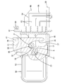
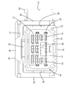
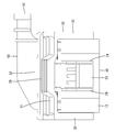
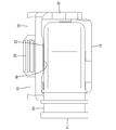
以下、本発明の実施例1を図1~図8に基づいて説明する。本実施例1に係るレバー式コネクタは、ハウジング10と、レバー30と、電線カバー50とを備えている。ハウジング10は、相手ハウジング90に嵌合可能とされている。なお、以下の説明において、前後方向については、両ハウジング10、90が嵌合開始時に互いに向き合う面側を前側とし、上下方向については、図4を除く各図を基準とする。また、左右方向は、図3及び図7を基準とする。
両ハウジング10、90の嵌合動作を開始するに先立ち、レバー30がハウジング10に対して仮係止位置に留め置かれる。仮係止位置では、操作部31の張出片40が電線カバー50のフラット面52に当接するとともに(図5を参照)、抜止片28がストッパ部35に当接することにより(図6を参照)、レバー30が仮係止位置から本係止位置に向かう方向とは反対側に回動されるのが規制される。また、仮係止位置では、図1に示すように、カム溝36の始端部37が導入溝25と連通して前方を向いて配置される。
以下、他の実施例を簡単に説明する。
(1)レバーは、全体として一枚板状のカム板で構成されるものであってもよい。
(2)上記実施例1とは逆に、高抵抗部がハウジング本体の下部に設けられ、低抵抗部がハウジング本体の上部に設けられるものであってもよい。また、高抵抗部と低抵抗部とがハウジング本体の左右両側に分かれて設けられるものであってもよい。
(3)高抵抗部と低抵抗部との抵抗差は、上記実施例1における端子金具の個数の差を起因とする場合に限らず、ガイド構造やシール構造などの摺動抵抗を発生させる他の要因で生じるものであってもよい。
19…電線
21…高抵抗部
22…低抵抗部
23…ハウジングロック部
30…レバー
31…操作部
32…カム部
33…軸受部
36…カム溝
40…張出片
41…レバーロック部
50…電線カバー
90…相手ハウジング
98…カムフォロア
Claims (4)
- 支軸が突設されたハウジングと、
前記支軸を受けて前記ハウジングに支持される軸受部と、嵌合操作時の力点となる操作部と、相手ハウジングの突起状のカムフォロアと係合し、前記軸受部を支点とする回動によって前記ハウジングと前記相手ハウジングとの嵌合を進めるカム溝とを有するレバーと、を備え、
前記カム溝と係合した前記カムフォロアの軸心が、前記ハウジングと前記相手ハウジングとの嵌合方向と直交する方向に関して、前記軸受部の軸心に対して前記操作部側に位置ずれしていることを特徴とするレバー式コネクタ。 - 前記ハウジングにおける前記嵌合方向と直交する方向の一側が他側よりも前記相手ハウジングとの嵌合抵抗が大きい領域となり、前記カム溝と係合した前記カムフォロアの軸心が前記ハウジングの前記一側に位置ずれしている請求項1記載のレバー式コネクタ。
- 前記レバーが前記操作部に撓み可能なレバーロック部を有し、前記ハウジングがハウジングロック部を有し、前記ハウジングと前記相手ハウジングとの嵌合完了時に前記レバーロック部が前記ハウジングロック部に弾性的に係止され、前記操作部が、前記レバーロック部を外側から覆う張出片を有している請求項1又は2記載のレバー式コネクタ。
- 前記ハウジングから引き出された電線を覆う電線カバーを備え、前記ハウジングと前記相手ハウジングとの嵌合開始時に前記張出片が前記電線カバーに当接していることを特徴とする請求項3記載のレバー式コネクタ。
Priority Applications (3)
| Application Number | Priority Date | Filing Date | Title |
|---|---|---|---|
| CN201780016930.8A CN108780969B (zh) | 2016-03-18 | 2017-02-27 | 杆式连接器 |
| KR1020187026711A KR102078758B1 (ko) | 2016-03-18 | 2017-02-27 | 레버식 커넥터 |
| US16/083,537 US10483692B2 (en) | 2016-03-18 | 2017-02-27 | Levery-type connector |
Applications Claiming Priority (2)
| Application Number | Priority Date | Filing Date | Title |
|---|---|---|---|
| JP2016054907A JP6610952B2 (ja) | 2016-03-18 | 2016-03-18 | レバー式コネクタ |
| JP2016-054907 | 2016-03-18 |
Publications (1)
| Publication Number | Publication Date |
|---|---|
| WO2017159304A1 true WO2017159304A1 (ja) | 2017-09-21 |
Family
ID=59850208
Family Applications (1)
| Application Number | Title | Priority Date | Filing Date |
|---|---|---|---|
| PCT/JP2017/007291 Ceased WO2017159304A1 (ja) | 2016-03-18 | 2017-02-27 | レバー式コネクタ |
Country Status (5)
| Country | Link |
|---|---|
| US (1) | US10483692B2 (ja) |
| JP (1) | JP6610952B2 (ja) |
| KR (1) | KR102078758B1 (ja) |
| CN (1) | CN108780969B (ja) |
| WO (1) | WO2017159304A1 (ja) |
Cited By (1)
| Publication number | Priority date | Publication date | Assignee | Title |
|---|---|---|---|---|
| DE102018217924B4 (de) | 2017-10-20 | 2022-05-12 | Lear Corporation | Elektrischer Anschluss mit Hilfshebel |
Families Citing this family (6)
| Publication number | Priority date | Publication date | Assignee | Title |
|---|---|---|---|---|
| JP6879231B2 (ja) * | 2018-03-06 | 2021-06-02 | 住友電装株式会社 | コネクタ |
| JP7092712B2 (ja) * | 2019-07-11 | 2022-06-28 | 矢崎総業株式会社 | レバー式コネクタ |
| JP7065057B2 (ja) | 2019-07-12 | 2022-05-11 | 矢崎総業株式会社 | レバー式コネクタ |
| DE102019129823A1 (de) * | 2019-11-05 | 2021-05-06 | Festool Gmbh | Verbindungsanordnung für eine handgeführte Werkzeugmaschine und handgeführte Werkzeugmaschine |
| JP7252518B2 (ja) * | 2020-01-13 | 2023-04-05 | 住友電装株式会社 | コネクタ |
| CN116154553A (zh) * | 2023-03-10 | 2023-05-23 | 中航光电科技股份有限公司 | 一种连接器的滑道型偏置锁紧装置 |
Citations (2)
| Publication number | Priority date | Publication date | Assignee | Title |
|---|---|---|---|---|
| JP2009070754A (ja) * | 2007-09-18 | 2009-04-02 | Hitachi Cable Ltd | レバー式コネクタ |
| JP2013246914A (ja) * | 2012-05-24 | 2013-12-09 | Sumitomo Wiring Syst Ltd | レバー式コネクタ |
Family Cites Families (25)
| Publication number | Priority date | Publication date | Assignee | Title |
|---|---|---|---|---|
| JPS573280A (en) | 1980-06-04 | 1982-01-08 | Fujitsu Ltd | Recording and deciding system for discrimination track |
| JP2598603Y2 (ja) * | 1992-08-19 | 1999-08-16 | 矢崎総業株式会社 | 低挿抜力コネクタ |
| JP3777083B2 (ja) * | 2000-07-11 | 2006-05-24 | 株式会社オートネットワーク技術研究所 | コネクタ及びコネクタ構造 |
| JP3573280B2 (ja) | 2001-06-26 | 2004-10-06 | 住友電装株式会社 | レバー式コネクタ |
| DE10223928A1 (de) * | 2001-05-29 | 2003-01-23 | Sumitomo Wiring Systems | Hebeltyp-Verbinder und Verfahren zum Zusammenbauen |
| JP2003036927A (ja) * | 2001-07-25 | 2003-02-07 | Yazaki Corp | レバー式コネクタ |
| JP3864772B2 (ja) * | 2001-12-07 | 2007-01-10 | 住友電装株式会社 | レバー式コネクタ |
| JP4191763B2 (ja) * | 2003-04-02 | 2008-12-03 | モレックス インコーポレーテッド | レバー型電気コネクタ組立体 |
| JP4556134B2 (ja) * | 2005-08-03 | 2010-10-06 | 住友電装株式会社 | コネクタ |
| JP4593480B2 (ja) * | 2006-01-11 | 2010-12-08 | 矢崎総業株式会社 | コネクタ構造 |
| JP4966625B2 (ja) * | 2006-10-27 | 2012-07-04 | 矢崎総業株式会社 | コネクタ |
| JP4901618B2 (ja) * | 2007-07-17 | 2012-03-21 | 矢崎総業株式会社 | レバー式コネクタ |
| JP2010003526A (ja) * | 2008-06-19 | 2010-01-07 | Jst Mfg Co Ltd | 仮嵌合構造を有する一対のコネクタハウジング |
| JP5211929B2 (ja) * | 2008-08-19 | 2013-06-12 | 住友電装株式会社 | レバー式コネクタ |
| JP5347936B2 (ja) * | 2009-12-10 | 2013-11-20 | 住友電装株式会社 | レバー式コネクタ |
| JP5293628B2 (ja) * | 2010-02-01 | 2013-09-18 | 日立電線株式会社 | コネクタ |
| JP2012074208A (ja) * | 2010-09-28 | 2012-04-12 | Hitachi Cable Ltd | コネクタ |
| JP4905586B1 (ja) * | 2010-12-21 | 2012-03-28 | 日立電線株式会社 | コネクタ |
| JP5624874B2 (ja) * | 2010-12-24 | 2014-11-12 | タイコエレクトロニクスジャパン合同会社 | レバー式コネクタ、ワイヤカバー |
| JP5673457B2 (ja) * | 2011-01-19 | 2015-02-18 | 日立金属株式会社 | コネクタ |
| JP5831061B2 (ja) * | 2011-01-19 | 2015-12-09 | 日立金属株式会社 | コネクタ |
| JP5784529B2 (ja) * | 2012-03-05 | 2015-09-24 | タイコエレクトロニクスジャパン合同会社 | レバー式コネクタ |
| US8784127B2 (en) * | 2012-06-11 | 2014-07-22 | Delphi Technologies, Inc. | Electrical connection system including mating assist lever that contains locking means and connector position assurance member that interacts therewith |
| JP2014165028A (ja) * | 2013-02-26 | 2014-09-08 | Sumitomo Wiring Syst Ltd | コネクタ |
| JP6252068B2 (ja) * | 2013-09-24 | 2017-12-27 | 矢崎総業株式会社 | レバー嵌合式コネクタ |
-
2016
- 2016-03-18 JP JP2016054907A patent/JP6610952B2/ja not_active Expired - Fee Related
-
2017
- 2017-02-27 CN CN201780016930.8A patent/CN108780969B/zh active Active
- 2017-02-27 KR KR1020187026711A patent/KR102078758B1/ko active Active
- 2017-02-27 US US16/083,537 patent/US10483692B2/en active Active
- 2017-02-27 WO PCT/JP2017/007291 patent/WO2017159304A1/ja not_active Ceased
Patent Citations (2)
| Publication number | Priority date | Publication date | Assignee | Title |
|---|---|---|---|---|
| JP2009070754A (ja) * | 2007-09-18 | 2009-04-02 | Hitachi Cable Ltd | レバー式コネクタ |
| JP2013246914A (ja) * | 2012-05-24 | 2013-12-09 | Sumitomo Wiring Syst Ltd | レバー式コネクタ |
Cited By (1)
| Publication number | Priority date | Publication date | Assignee | Title |
|---|---|---|---|---|
| DE102018217924B4 (de) | 2017-10-20 | 2022-05-12 | Lear Corporation | Elektrischer Anschluss mit Hilfshebel |
Also Published As
| Publication number | Publication date |
|---|---|
| US20190074633A1 (en) | 2019-03-07 |
| CN108780969A (zh) | 2018-11-09 |
| CN108780969B (zh) | 2020-08-07 |
| KR102078758B1 (ko) | 2020-02-19 |
| JP2017168391A (ja) | 2017-09-21 |
| KR20180110136A (ko) | 2018-10-08 |
| JP6610952B2 (ja) | 2019-11-27 |
| US10483692B2 (en) | 2019-11-19 |
Similar Documents
| Publication | Publication Date | Title |
|---|---|---|
| JP6610952B2 (ja) | レバー式コネクタ | |
| JP6193060B2 (ja) | レバー式電気コネクタ | |
| JP6424190B2 (ja) | レバー式コネクタ | |
| JP6880454B2 (ja) | レバー式コネクタ | |
| JP2010049840A (ja) | レバー式コネクタ | |
| JP2018018583A (ja) | コネクタ | |
| JP2015220048A (ja) | コネクタ | |
| CN104733908A (zh) | 杆式电气连接器 | |
| CN104145382B (zh) | 杆式连接器 | |
| JP2018067379A (ja) | コネクタ | |
| JP4497038B2 (ja) | レバー式コネクタ | |
| WO2021145172A1 (ja) | コネクタ | |
| JP2018018584A (ja) | コネクタ | |
| JP6243277B2 (ja) | シールドコネクタ | |
| JP4613747B2 (ja) | コネクタ | |
| JP6673017B2 (ja) | コネクタ | |
| JP6902209B2 (ja) | レバー式コネクタ | |
| JP2016006726A (ja) | レバー式コネクタ | |
| JP2018018695A (ja) | コネクタ | |
| US10103490B2 (en) | Lever-type connector | |
| JP2017054584A (ja) | レバー式コネクタ | |
| US20250038455A1 (en) | Lever-type connector | |
| WO2016072234A1 (ja) | レバー式コネクタ | |
| JP6580464B2 (ja) | コネクタ | |
| JP6668950B2 (ja) | コネクタ |
Legal Events
| Date | Code | Title | Description |
|---|---|---|---|
| ENP | Entry into the national phase |
Ref document number: 20187026711 Country of ref document: KR Kind code of ref document: A |
|
| WWE | Wipo information: entry into national phase |
Ref document number: 1020187026711 Country of ref document: KR |
|
| NENP | Non-entry into the national phase |
Ref country code: DE |
|
| 121 | Ep: the epo has been informed by wipo that ep was designated in this application |
Ref document number: 17766308 Country of ref document: EP Kind code of ref document: A1 |
|
| 122 | Ep: pct application non-entry in european phase |
Ref document number: 17766308 Country of ref document: EP Kind code of ref document: A1 |