WO2017154403A1 - 含フッ素エーテル化合物、磁気記録媒体用潤滑剤および磁気記録媒体 - Google Patents
含フッ素エーテル化合物、磁気記録媒体用潤滑剤および磁気記録媒体 Download PDFInfo
- Publication number
- WO2017154403A1 WO2017154403A1 PCT/JP2017/003165 JP2017003165W WO2017154403A1 WO 2017154403 A1 WO2017154403 A1 WO 2017154403A1 JP 2017003165 W JP2017003165 W JP 2017003165W WO 2017154403 A1 WO2017154403 A1 WO 2017154403A1
- Authority
- WO
- WIPO (PCT)
- Prior art keywords
- formula
- group
- fluorine
- layer
- compound
- Prior art date
Links
- 0 CC(C)(N*)NC(C)(C)NON*(*)NOC Chemical compound CC(C)(N*)NC(C)(C)NON*(*)NOC 0.000 description 4
- LQNHRNOPWKZUSN-UHFFFAOYSA-N NCC1CCC1 Chemical compound NCC1CCC1 LQNHRNOPWKZUSN-UHFFFAOYSA-N 0.000 description 2
Images

Classifications
-
- C—CHEMISTRY; METALLURGY
- C07—ORGANIC CHEMISTRY
- C07C—ACYCLIC OR CARBOCYCLIC COMPOUNDS
- C07C43/00—Ethers; Compounds having groups, groups or groups
- C07C43/02—Ethers
- C07C43/20—Ethers having an ether-oxygen atom bound to a carbon atom of a six-membered aromatic ring
- C07C43/23—Ethers having an ether-oxygen atom bound to a carbon atom of a six-membered aromatic ring containing hydroxy or O-metal groups
-
- C—CHEMISTRY; METALLURGY
- C07—ORGANIC CHEMISTRY
- C07C—ACYCLIC OR CARBOCYCLIC COMPOUNDS
- C07C43/00—Ethers; Compounds having groups, groups or groups
- C07C43/02—Ethers
- C07C43/03—Ethers having all ether-oxygen atoms bound to acyclic carbon atoms
- C07C43/14—Unsaturated ethers
- C07C43/178—Unsaturated ethers containing hydroxy or O-metal groups
- C07C43/1786—Unsaturated ethers containing hydroxy or O-metal groups containing halogen
-
- C—CHEMISTRY; METALLURGY
- C07—ORGANIC CHEMISTRY
- C07D—HETEROCYCLIC COMPOUNDS
- C07D277/00—Heterocyclic compounds containing 1,3-thiazole or hydrogenated 1,3-thiazole rings
- C07D277/02—Heterocyclic compounds containing 1,3-thiazole or hydrogenated 1,3-thiazole rings not condensed with other rings
- C07D277/20—Heterocyclic compounds containing 1,3-thiazole or hydrogenated 1,3-thiazole rings not condensed with other rings having two or three double bonds between ring members or between ring members and non-ring members
- C07D277/22—Heterocyclic compounds containing 1,3-thiazole or hydrogenated 1,3-thiazole rings not condensed with other rings having two or three double bonds between ring members or between ring members and non-ring members with only hydrogen atoms, hydrocarbon or substituted hydrocarbon radicals, directly attached to ring carbon atoms
- C07D277/24—Radicals substituted by oxygen atoms
-
- C—CHEMISTRY; METALLURGY
- C07—ORGANIC CHEMISTRY
- C07D—HETEROCYCLIC COMPOUNDS
- C07D303/00—Compounds containing three-membered rings having one oxygen atom as the only ring hetero atom
- C07D303/02—Compounds containing oxirane rings
- C07D303/12—Compounds containing oxirane rings with hydrocarbon radicals, substituted by singly or doubly bound oxygen atoms
- C07D303/18—Compounds containing oxirane rings with hydrocarbon radicals, substituted by singly or doubly bound oxygen atoms by etherified hydroxyl radicals
- C07D303/20—Ethers with hydroxy compounds containing no oxirane rings
- C07D303/24—Ethers with hydroxy compounds containing no oxirane rings with polyhydroxy compounds
- C07D303/26—Ethers with hydroxy compounds containing no oxirane rings with polyhydroxy compounds having one or more free hydroxyl radicals
-
- C—CHEMISTRY; METALLURGY
- C07—ORGANIC CHEMISTRY
- C07D—HETEROCYCLIC COMPOUNDS
- C07D333/00—Heterocyclic compounds containing five-membered rings having one sulfur atom as the only ring hetero atom
- C07D333/02—Heterocyclic compounds containing five-membered rings having one sulfur atom as the only ring hetero atom not condensed with other rings
- C07D333/04—Heterocyclic compounds containing five-membered rings having one sulfur atom as the only ring hetero atom not condensed with other rings not substituted on the ring sulphur atom
- C07D333/06—Heterocyclic compounds containing five-membered rings having one sulfur atom as the only ring hetero atom not condensed with other rings not substituted on the ring sulphur atom with only hydrogen atoms, hydrocarbon or substituted hydrocarbon radicals, directly attached to the ring carbon atoms
- C07D333/14—Radicals substituted by singly bound hetero atoms other than halogen
- C07D333/16—Radicals substituted by singly bound hetero atoms other than halogen by oxygen atoms
-
- C—CHEMISTRY; METALLURGY
- C07—ORGANIC CHEMISTRY
- C07D—HETEROCYCLIC COMPOUNDS
- C07D409/00—Heterocyclic compounds containing two or more hetero rings, at least one ring having sulfur atoms as the only ring hetero atoms
- C07D409/02—Heterocyclic compounds containing two or more hetero rings, at least one ring having sulfur atoms as the only ring hetero atoms containing two hetero rings
- C07D409/12—Heterocyclic compounds containing two or more hetero rings, at least one ring having sulfur atoms as the only ring hetero atoms containing two hetero rings linked by a chain containing hetero atoms as chain links
-
- C—CHEMISTRY; METALLURGY
- C10—PETROLEUM, GAS OR COKE INDUSTRIES; TECHNICAL GASES CONTAINING CARBON MONOXIDE; FUELS; LUBRICANTS; PEAT
- C10M—LUBRICATING COMPOSITIONS; USE OF CHEMICAL SUBSTANCES EITHER ALONE OR AS LUBRICATING INGREDIENTS IN A LUBRICATING COMPOSITION
- C10M105/00—Lubricating compositions characterised by the base-material being a non-macromolecular organic compound
- C10M105/50—Lubricating compositions characterised by the base-material being a non-macromolecular organic compound containing halogen
- C10M105/54—Lubricating compositions characterised by the base-material being a non-macromolecular organic compound containing halogen containing carbon, hydrogen, halogen and oxygen
-
- C—CHEMISTRY; METALLURGY
- C10—PETROLEUM, GAS OR COKE INDUSTRIES; TECHNICAL GASES CONTAINING CARBON MONOXIDE; FUELS; LUBRICANTS; PEAT
- C10M—LUBRICATING COMPOSITIONS; USE OF CHEMICAL SUBSTANCES EITHER ALONE OR AS LUBRICATING INGREDIENTS IN A LUBRICATING COMPOSITION
- C10M107/00—Lubricating compositions characterised by the base-material being a macromolecular compound
- C10M107/38—Lubricating compositions characterised by the base-material being a macromolecular compound containing halogen
-
- G—PHYSICS
- G11—INFORMATION STORAGE
- G11B—INFORMATION STORAGE BASED ON RELATIVE MOVEMENT BETWEEN RECORD CARRIER AND TRANSDUCER
- G11B5/00—Recording by magnetisation or demagnetisation of a record carrier; Reproducing by magnetic means; Record carriers therefor
- G11B5/62—Record carriers characterised by the selection of the material
- G11B5/72—Protective coatings, e.g. anti-static or antifriction
- G11B5/725—Protective coatings, e.g. anti-static or antifriction containing a lubricant, e.g. organic compounds
- G11B5/7253—Fluorocarbon lubricant
- G11B5/7257—Perfluoropolyether lubricant
-
- G—PHYSICS
- G11—INFORMATION STORAGE
- G11B—INFORMATION STORAGE BASED ON RELATIVE MOVEMENT BETWEEN RECORD CARRIER AND TRANSDUCER
- G11B5/00—Recording by magnetisation or demagnetisation of a record carrier; Reproducing by magnetic means; Record carriers therefor
- G11B5/62—Record carriers characterised by the selection of the material
- G11B5/73—Base layers, i.e. all non-magnetic layers lying under a lowermost magnetic recording layer, e.g. including any non-magnetic layer in between a first magnetic recording layer and either an underlying substrate or a soft magnetic underlayer
- G11B5/733—Base layers, i.e. all non-magnetic layers lying under a lowermost magnetic recording layer, e.g. including any non-magnetic layer in between a first magnetic recording layer and either an underlying substrate or a soft magnetic underlayer characterised by the addition of non-magnetic particles
-
- C—CHEMISTRY; METALLURGY
- C10—PETROLEUM, GAS OR COKE INDUSTRIES; TECHNICAL GASES CONTAINING CARBON MONOXIDE; FUELS; LUBRICANTS; PEAT
- C10M—LUBRICATING COMPOSITIONS; USE OF CHEMICAL SUBSTANCES EITHER ALONE OR AS LUBRICATING INGREDIENTS IN A LUBRICATING COMPOSITION
- C10M2211/00—Organic non-macromolecular compounds containing halogen as ingredients in lubricant compositions
- C10M2211/04—Organic non-macromolecular compounds containing halogen as ingredients in lubricant compositions containing carbon, hydrogen, halogen, and oxygen
- C10M2211/042—Alcohols; Ethers; Aldehydes; Ketones
- C10M2211/0425—Alcohols; Ethers; Aldehydes; Ketones used as base material
-
- C—CHEMISTRY; METALLURGY
- C10—PETROLEUM, GAS OR COKE INDUSTRIES; TECHNICAL GASES CONTAINING CARBON MONOXIDE; FUELS; LUBRICANTS; PEAT
- C10M—LUBRICATING COMPOSITIONS; USE OF CHEMICAL SUBSTANCES EITHER ALONE OR AS LUBRICATING INGREDIENTS IN A LUBRICATING COMPOSITION
- C10M2213/00—Organic macromolecular compounds containing halogen as ingredients in lubricant compositions
- C10M2213/04—Organic macromolecular compounds containing halogen as ingredients in lubricant compositions obtained from monomers containing carbon, hydrogen, halogen and oxygen
- C10M2213/043—Organic macromolecular compounds containing halogen as ingredients in lubricant compositions obtained from monomers containing carbon, hydrogen, halogen and oxygen used as base material
-
- C—CHEMISTRY; METALLURGY
- C10—PETROLEUM, GAS OR COKE INDUSTRIES; TECHNICAL GASES CONTAINING CARBON MONOXIDE; FUELS; LUBRICANTS; PEAT
- C10N—INDEXING SCHEME ASSOCIATED WITH SUBCLASS C10M RELATING TO LUBRICATING COMPOSITIONS
- C10N2030/00—Specified physical or chemical properties which is improved by the additive characterising the lubricating composition, e.g. multifunctional additives
- C10N2030/06—Oiliness; Film-strength; Anti-wear; Resistance to extreme pressure
-
- C—CHEMISTRY; METALLURGY
- C10—PETROLEUM, GAS OR COKE INDUSTRIES; TECHNICAL GASES CONTAINING CARBON MONOXIDE; FUELS; LUBRICANTS; PEAT
- C10N—INDEXING SCHEME ASSOCIATED WITH SUBCLASS C10M RELATING TO LUBRICATING COMPOSITIONS
- C10N2040/00—Specified use or application for which the lubricating composition is intended
- C10N2040/14—Electric or magnetic purposes
- C10N2040/18—Electric or magnetic purposes in connection with recordings on magnetic tape or disc
-
- C—CHEMISTRY; METALLURGY
- C10—PETROLEUM, GAS OR COKE INDUSTRIES; TECHNICAL GASES CONTAINING CARBON MONOXIDE; FUELS; LUBRICANTS; PEAT
- C10N—INDEXING SCHEME ASSOCIATED WITH SUBCLASS C10M RELATING TO LUBRICATING COMPOSITIONS
- C10N2050/00—Form in which the lubricant is applied to the material being lubricated
- C10N2050/023—Multi-layer lubricant coatings
- C10N2050/025—Multi-layer lubricant coatings in the form of films or sheets
Definitions
- the present invention relates to a fluorine-containing ether compound suitable for use as a lubricant for magnetic recording media.
- a magnetic recording medium suitable for a high recording density In order to improve the recording density of a magnetic recording / reproducing apparatus, development of a magnetic recording medium suitable for a high recording density is underway.
- a magnetic recording medium in which a recording layer is formed on a substrate and a protective layer such as carbon is formed on the recording layer.
- the protective layer protects information recorded on the recording layer and improves the slidability of the magnetic head.
- the durability of the magnetic recording medium cannot be sufficiently obtained only by providing the protective layer on the recording layer. For this reason, generally, a lubricant is applied to the surface of the protective layer to form a lubricant layer.
- Patent Document 1 discloses a compound in which substituents having a plurality of hydroxyl groups at both terminal portions and having a shortest distance between the hydroxyl groups of 3 atoms or more are arranged.
- Patent Document 2 discloses a fluoropolyether compound having an aromatic group at one end and a hydroxyl group at the other end.
- Patent Document 3 discloses a compound having a perfluoropolyether main chain, an aromatic group and a hydroxyl group at the end of the molecule, and the aromatic group and the hydroxyl group bonded to different carbon atoms. It is disclosed.
- the magnetic recording / reproducing apparatus it is required to further reduce the flying height of the magnetic head. For this reason, it is required to further reduce the thickness of the lubricating layer in the magnetic recording medium.
- the thickness of the lubricating layer is reduced, the coverage of the lubricating layer is lowered, and the chemical substance resistance and wear resistance of the magnetic recording medium tend to be lowered.
- the present invention has been made in view of the above circumstances, and is suitable for use as a material for a lubricant for magnetic recording media capable of forming a lubricating layer capable of obtaining excellent chemical substance resistance and wear resistance even when the thickness is small. It is an object to provide a fluorine ether compound. Another object of the present invention is to provide a lubricant for magnetic recording media containing the fluorine-containing ether compound of the present invention. Another object of the present invention is to provide a magnetic recording medium having excellent reliability and durability having a lubricating layer containing the fluorine-containing ether compound of the present invention.
- an end group containing an organic group having at least one double bond or triple bond is disposed at one end of the perfluoropolyether chain via a divalent linking group bonded by etheric oxygen,
- the other end of the polyether chain contains two or three polar groups, each polar group is bonded to a different carbon atom, and the carbon groups to which the polar group is bonded are not bonded to each other.
- the inventors have found that a fluorine-containing ether compound having a terminal group bonded via a linking group containing a carbon atom may be used, and have conceived the present invention. That is, the present invention relates to the following matters.
- R 1 is a terminal group containing an organic group having at least one double bond or triple bond
- R 2 is a divalent linking group bonded to R 1 by etheric oxygen
- R 3 is a perfluoropolyether chain
- R 4 contains two or three polar groups, each polar group is bonded to a different carbon atom, and the carbon atoms to which the polar group is bonded are polar This is a terminal group bonded through a linking group containing a carbon atom to which the group is not bonded.
- R 1 in the formula (1) is any one of a terminal group including an aromatic ring, a terminal group including a heterocyclic ring, a terminal group including an alkenyl group, or a terminal group including an alkynyl group.
- the fluorine-containing ether compound according to any one of [1] to [5].
- a lubricant for magnetic recording media comprising the fluorine-containing ether compound according to any one of [1] to [9].
- a magnetic recording medium in which at least a magnetic layer, a protective layer, and a lubrication layer are sequentially provided on a substrate, wherein the lubrication layer includes the lubrication layer according to any one of [1] to [9].
- a magnetic recording medium comprising a fluorine ether compound.
- the fluorine-containing ether compound of the present invention is a compound represented by the above formula (1) and is suitable as a material for a lubricant for magnetic recording media. Since the lubricant for magnetic recording media of the present invention contains the fluorine-containing ether compound of the present invention, it can form a lubricating layer that provides excellent chemical resistance and wear resistance even when the thickness is small. Since the magnetic recording medium of the present invention is provided with a lubricating layer having excellent chemical substance resistance and wear resistance, it has excellent reliability and durability.
- FIG. 1 is a schematic cross-sectional view showing an embodiment of a magnetic recording medium of the present invention.
- the fluorine-containing ether compound of this embodiment is represented by the following formula (1).
- R 1 is a terminal group containing an organic group having at least one double bond or triple bond
- R 2 is a divalent linking group bonded to R 1 by etheric oxygen
- R 3 is a perfluoropolyether chain
- R 4 contains two or three polar groups, each polar group is bonded to a different carbon atom, and the carbon atoms to which the polar group is bonded are polar This is a terminal group bonded through a linking group containing a carbon atom to which the group is not bonded.
- the lubricant layer was formed on the protective layer of the magnetic recording medium using the lubricant for the magnetic recording medium containing the fluorine-containing ether compound of the present embodiment (hereinafter sometimes abbreviated as “lubricant”). The reason why excellent chemical substance resistance and wear resistance can be obtained even when the thickness is small will be described.
- the fluorine-containing ether compound of the present embodiment has R 2 at one end of a perfluoropolyether chain represented by R 3 (hereinafter sometimes abbreviated as “PFPE chain”).
- PFPE chain A terminal group containing an organic group having at least one double bond or triple bond represented by R 1 is arranged through a divalent linking group bonded to R 1 by etheric oxygen represented by .
- the PFPE chain covers the surface of the protective layer and reduces the frictional force between the magnetic head and the protective layer in the lubricating layer containing the fluorine-containing ether compound of this embodiment.
- the terminal group containing an organic group having at least one double bond or triple bond represented by R 1 is an intermolecular interaction of an organic group having at least one double bond or triple bond, and / or Due to the interaction between the organic group and the protective layer, the wear resistance in the lubricating layer containing the fluorine-containing ether compound of this embodiment is improved. Therefore, the lubricating layer containing the fluorine-containing ether compound of the present embodiment is superior to, for example, a lubricating layer containing a fluorine-containing ether compound in which a hydroxyl group is arranged instead of the terminal group represented by R 1 . Abrasion resistance is obtained.
- the terminal group represented by R 4 includes two or three polar groups. Two or three polar groups contained in the terminal group represented by R 4 are bonded to the fluorine-containing ether compound and the protective layer in the lubricating layer containing the fluorine-containing ether compound of the present embodiment, and are resistant to chemical substances. In addition, it improves wear resistance and suppresses pickup.
- two or three polar groups contained in the end group represented by R 4 are bonded to different carbon atoms, and the carbon atoms bonded to the polar groups are polar. They are bonded through a linking group containing an unbonded carbon atom.
- the fluorine-containing ether compound having an end group represented by R 4 for example, two polar groups contained in the end group are bonded to different carbon atoms, and the carbon atoms to which the polar groups are bonded are bonded to each other. Compared with the fluorine ether compound, it is hard to aggregate.
- the fluorinated ether compound present without adhering (adsorbing) to the protective layer aggregates and adheres to the magnetic head as foreign matter (smear). Can be prevented and pickup is suppressed. Further, since the fluorinated ether compounds are less likely to aggregate, the fluorinated ether compound in the lubricating layer is likely to be disposed in a state of extending and extending in the surface direction on the protective layer.
- the lubricant containing the above-mentioned fluorine-containing ether compound can cover the surface of the protective layer with a high coverage even if the thickness is reduced, and can form a lubricating layer having excellent chemical substance resistance.
- R 4 contains two or three polar groups, each polar group is bonded to a different carbon atom, and the polar group is bonded. Carbon atoms that are bonded to each other through a linking group containing a carbon atom to which no polar group is bonded.
- the terminal group represented by R 4 contributes to the adhesion between the protective layer to which the lubricant containing the fluorine-containing ether compound of this embodiment is applied and the lubricant layer formed by applying the lubricant.
- R 4 in the formula (1) can be appropriately selected according to the performance required for the lubricant containing the fluorine-containing ether compound.
- the fluorinated ether compound of the present embodiment represented by the formula (1) is an asymmetric compound in which different terminal groups (R 1 , R 4 ) are bonded to both ends of the PFPE chain (R 3 ).
- R 1 , R 4 the same end groups are bonded to both ends due to the synergistic effect of different end groups (R 1 , R 4 ) bonded to the molecular ends. Excellent chemical resistance and wear resistance are obtained compared to the compounds.
- Examples of the polar group for R 4 include a hydroxyl group, an amino group, a carboxyl group, and a thiol group.
- the ether bond (—O—) is not included in the polar group in R 4 .
- the polar group in the terminal group containing two or three polar groups of R 4 is preferably a hydroxyl group because a lubricating layer containing a fluorinated ether compound having good adhesion to the protective layer is obtained.
- R 4 in the formula (1) is preferably any terminal group of the following formulas (2-1) to (2-4). Such R 4 contributes to high adhesion and coverage between the protective layer to which the lubricant containing the fluorine-containing ether compound of the present embodiment is applied and the lubricant layer formed by applying the lubricant.
- p1 is 1 to 2.
- p2 is 1 to 5
- the distance between the hydroxyl groups in the terminal group represented by the formula (2-1) is appropriate, the adhesiveness with the protective layer is excellent, and the coverage is High lubricating layer can be formed.
- p2 is preferably 1 to 2, and most preferably 1.
- s when s is 2 to 5, the distance between the hydroxyl group on the R 3 side and the terminal hydroxyl group is appropriate, and the lubricating layer has excellent adhesion with the protective layer and high coverage. Can be formed. s is preferably 2 to 3, and most preferably 2.
- t when t is 1 to 5, the distance between the hydroxyl group on the R 3 side and the terminal hydroxyl group is appropriate, and the lubricating layer has excellent adhesion with the protective layer and high coverage. Can be formed.
- t is preferably 1 to 2, and most preferably 1.
- R 3 is a perfluoropolyether chain (PFPE chain).
- PFPE chain perfluoropolyether chain
- the PFPE chain covers the surface of the protective layer and provides lubricity to the lubricating layer to protect the magnetic head. Reduce friction with the layer.
- R 3 is not particularly limited, and can be appropriately selected according to the performance required for the lubricant containing the fluorine-containing ether compound.
- R 3 is preferably a PFPE chain represented by the following formula (3) because the synthesis of the fluorine-containing ether compound is easy.
- the arrangement order of the repeating units (CF 2 —CF 2 —O) and (CF 2 —O) is not particularly limited.
- the number m of (CF 2 —CF 2 —O) and the number n of (CF 2 —O) may be the same or different.
- Formula (3) includes one of a random copolymer, a block copolymer, and an alternating copolymer composed of monomer units (CF 2 —CF 2 —O) and (CF 2 —O). Also good.
- R 3 in Formula (1) is Formula (3)
- m is 1 to 30, preferably 1 to 20, and more preferably 1 to 15.
- n is 0 to 30, preferably 0 to 20, and more preferably 0 to 15.
- n is 0, m is preferably 1-17.
- R 3 may be the following formula (4) or the following formula (5).
- u when u is 1 to 30, the number average molecular weight of the fluorinated ether compound of the present embodiment tends to be in a preferred range.
- u is preferably from 3 to 20, and more preferably from 4 to 10.
- v is 1 to 30, the number average molecular weight of the fluorinated ether compound of this embodiment tends to be in a preferred range.
- v is preferably from 3 to 20, and more preferably from 4 to 10.
- R 3 in the formula (1) is any one of the formulas (3) to (5), it is preferable because the synthesis of the fluorine-containing ether compound is easy. Further, when R 3 in the formula (1) is any one of the formulas (3) to (5), the number of oxygen atoms relative to the number of carbon atoms in the perfluoropolyether chain (the number of ether bonds (—O—)) ) Is appropriate. For this reason, it becomes a fluorine-containing ether compound which has moderate hardness. Therefore, the fluorine-containing ether compound applied on the protective layer is less likely to aggregate on the protective layer, and a thinner lubricating layer can be formed with a sufficient coverage. Further, if R 3 in the formula (1) is an expression (3), since the raw material is easily available, and more preferred.
- R 1 in the formula (1) is a terminal group including an organic group having at least one double bond or triple bond.
- R 1 is preferably any one of a terminal group containing an aromatic ring, a terminal group containing a heterocyclic ring, a terminal group containing an alkenyl group, or a terminal group containing an alkynyl group.
- Specific examples of the terminal group containing an organic group having at least one double bond or triple bond used as R 1 include a phenyl group, a methoxyphenyl group, a naphthyl group, a benzyl group, a methoxybenzyl group, and a naphthylmethyl.
- the terminal group containing an organic group having at least one double bond or triple bond may have a substituent such as an alkyl group, an alkoxy group, a hydroxyl group, a thiol group, a carboxyl group, a carbonyl group, or an amino group.
- R 1 is in particular a phenyl group, p-methoxyphenyl group, naphthyl group, p-methoxybenzyl group, thienylethyl group, methylpyrazolylmethyl group, methylthiazolylethyl group, furfuryl group, butenyl group, allyl group, propargyl group , A benzyl group or a naphthylmethyl group is preferable.
- R 1 is a preferred example of these, a fluorine-containing ether compound capable of forming a lubricating layer having superior wear resistance is obtained.
- R 2 in the formula (1) is a divalent linking group bonded to R 1 by etheric oxygen.
- the divalent linking group represented by R 2 is not particularly limited as long as it is bonded to R 1 by etheric oxygen, depending on the performance required for the lubricant containing the fluorine-containing ether compound. It can be selected appropriately.
- the divalent linking group represented by R 2 is 1 in order to improve the adhesion between the protective layer to which the lubricant containing the fluorine-containing ether compound is applied and the lubricating layer formed by applying the lubricant. It is preferable to have two or more polar groups. Examples of the polar group contained in the linking group include a hydroxyl group, a carboxyl group, an amino group, and an aminocarboxyl group, and a hydroxyl group is preferable. When the divalent linking group represented by R 2 contains at least one hydroxyl group, particularly when the protective layer to which the lubricant is applied is formed of carbon or carbon containing nitrogen, Adhesion with the lubricating layer containing the fluorine-containing ether compound is further improved.
- the number of polar groups that the linking group has is not particularly limited, and may be one or plural. It may be.
- the number of polar groups possessed by the linking group is preferably 4 or less in order to prevent the number average molecular weight of the fluorinated ether compound from becoming too large.
- the divalent linking group represented by R 2 preferably has 1 to 20 carbon atoms. It can prevent that the number average molecular weight of a fluorine-containing ether compound becomes large too much that a carbon atom number is 20 or less. More preferably, the linking group has 3 to 12 carbon atoms.
- R 2 in the formula (1) specifically, it is preferably represented by the following formula (6).
- the divalent linking group represented by R 2 contains one or more hydroxyl groups, whereby the adhesion between the protective layer and the lubricating layer becomes better.
- w is 4 or less, it can prevent that the number average molecular weight of a fluorine-containing ether compound becomes large too much, and is preferable. More preferably, w is 1 to 2.
- R 2 in the formula (1) may be —O— because the synthesis of the fluorine-containing ether compound is easy.
- the fluorine-containing ether compound of this embodiment is preferably any compound represented by the following formulas (A) to (AC). Note that the number of repetitions such as m and n in the formulas (A) to (AC) is a value indicating an average value, and thus is not necessarily an integer.
- the compound represented by the formula (1) is any one of the compounds represented by the above formulas (A) to (AC), the raw material is easily available and excellent chemical resistance and wear resistance even when the thickness is small. Is preferable because a lubricating layer can be formed.
- the number average molecular weight of the fluorinated ether compound of the present embodiment is preferably in the range of 500 to 10,000.
- the lubricant containing the fluorine-containing ether compound of the present embodiment is difficult to evaporate, and the lubricant can be prevented from evaporating and transferring to the magnetic head.
- the number average molecular weight of the fluorinated ether compound is more preferably 1000 or more. Further, when the number average molecular weight is 10,000 or less, the viscosity of the fluorine-containing ether compound becomes appropriate, and a thin lubricating layer can be easily formed by applying a lubricant containing this.
- the number average molecular weight of the fluorinated ether compound is preferably 3000 or less because the viscosity becomes easy to handle when applied to a lubricant.
- the number average molecular weight is a value measured by 1 H-NMR and 19 F-NMR by AVANCE III400 manufactured by Bruker BioSpin.
- NMR nuclear magnetic resonance
- the sample was diluted in a hexafluorobenzene / d-acetone (4/1 v / v) solvent and used for the measurement.
- the standard of 19 F-NMR chemical shift was set to 164.7 ppm for the hexafluorobenzene peak, and the standard of 1 H-NMR chemical shift was set to 2.2 ppm for the acetone peak.
- the manufacturing method of the fluorine-containing ether compound of this embodiment is not specifically limited, It can manufacture using a conventionally well-known manufacturing method.
- the fluorine-containing ether compound of this embodiment can be manufactured using the manufacturing method shown below, for example.
- the hydroxyl group of the hydroxymethyl group arranged at one terminal of the fluorine-based compound is substituted with the terminal group composed of R 1 —R 2 — in the formula (1) (first reaction).
- the hydroxyl group of the hydroxymethyl group located at the other end is substituted with the end group consisting of —R 4 in the formula (1) (second reaction).
- the first reaction and the second reaction can be performed using a conventionally known method, and can be appropriately determined according to the types of R 1 , R 2 , and R 4 in formula (1).
- either of the first reaction and the second reaction may be performed first.
- the compound represented by Formula (1) is obtained.
- the fluorine-containing ether compound whose R ⁇ 2 > is represented by Formula (6)
- an epoxy compound can be synthesized using an alcohol having a structure corresponding to the terminal group represented by R 1 of the fluorine-containing ether compound to be produced, and epichlorohydrin or epibromohydrin.
- an epoxy compound represented by the formula (12) described later it can be obtained by reacting thiophene ethanol and epichlorohydrin in the presence of a base.
- the fluorine-containing ether compound of the present embodiment is a compound represented by the above formula (1). Therefore, when the lubricant layer is formed on the protective layer using the lubricant containing the lubricant, the surface of the protective layer is covered with the PFPE chain represented by R 3 in the formula (1), and the magnetic head and the protective layer. And the frictional force is reduced. Further, in the lubricating layer formed using the lubricant containing the fluorine-containing ether compound of the present embodiment, due to the intermolecular interaction in the terminal group represented by R 1 and / or the interaction between the terminal group and the protective layer, Excellent wear resistance is obtained.
- the PFPE chain is brought into close contact with the protective layer by the bond between the two or three polar groups of R 4 connected to the PFPE chain and the protective layer. Therefore, according to the fluorine-containing ether compound of the present embodiment, the lubricating layer and the protective layer are firmly bonded, and a lubricating layer having excellent chemical substance resistance and wear resistance can be obtained.
- the lubricant for magnetic recording media of this embodiment contains a fluorine-containing ether compound represented by the formula (1).
- the lubricant of the present embodiment requires a known material used as a lubricant material as long as it does not impair the characteristics due to the inclusion of the fluorine-containing ether compound represented by the formula (1). It can be mixed and used accordingly. Specific examples of known materials include FOMBLIN (registered trademark) ZDIAC, FOMBLIN ZDEAL, FOMBLIN AM-2001 (manufactured by Solvey Solexis), Moresco A20H (manufactured by Moresco), and the like.
- the known material used in combination with the lubricant of this embodiment preferably has a number average molecular weight of 1000 to 10,000.
- the lubricant of this embodiment contains other materials of the fluorine-containing ether compound represented by formula (1), the inclusion of the fluorine-containing ether compound represented by formula (1) in the lubricant of this embodiment
- the amount is preferably 50% by mass or more, and more preferably 70% by mass or more.
- the lubricant of this embodiment contains the fluorine-containing ether compound represented by the formula (1), the surface of the protective layer can be coated with a high coverage even when the thickness is reduced, and the adhesiveness to the protective layer is improved. An excellent lubricating layer can be formed. Therefore, according to the lubricant of the present embodiment, a lubricating layer having excellent chemical substance resistance and wear resistance can be obtained even if the thickness is small. Moreover, since the lubricant of this embodiment contains the fluorine-containing ether compound represented by the formula (1), the fluorine-containing ether compound in the lubricant layer that is present without adhering (adsorbing) to the protective layer is present. , Hard to agglomerate.
- the lubricants of this embodiment since it contains a fluorine-containing ether compound represented by the formula (1), in the organic group having at least one double or triple bond in the terminal group represented by R 1 Due to the intermolecular interaction and / or the interaction between the organic group and the protective layer, a lubricating layer having excellent wear resistance can be obtained.
- FIG. 1 is a schematic sectional view showing an embodiment of the magnetic recording medium of the present invention.
- the magnetic recording medium 10 of this embodiment includes an adhesion layer 12, a soft magnetic layer 13, a first underlayer 14, a second underlayer 15, a magnetic layer 16, a protective layer 17 on a substrate 11.
- the lubricating layer 18 is sequentially provided.
- substrate for example, a nonmagnetic substrate in which a film made of NiP or NiP alloy is formed on a base made of a metal such as Al or an Al alloy or an alloy material can be used.
- the substrate 11 may be a nonmagnetic substrate made of a nonmetallic material such as glass, ceramics, silicon, silicon carbide, carbon, or resin, or NiP or NiP alloy on a base made of these nonmetallic materials.
- a nonmagnetic substrate on which the above film is formed may be used.
- the adhesion layer 12 prevents the corrosion of the substrate 11 when the substrate 11 and the soft magnetic layer 13 provided on the adhesion layer 12 are in contact with each other.
- the material of the adhesion layer 12 can be appropriately selected from, for example, Cr, Cr alloy, Ti, Ti alloy and the like.
- the adhesion layer 12 can be formed by, for example, a sputtering method.
- the soft magnetic layer 13 preferably has a structure in which a first soft magnetic film, an intermediate layer made of a Ru film, and a second soft magnetic film are sequentially laminated. That is, the soft magnetic layer 13 has a structure in which the soft magnetic films above and below the intermediate layer are anti-ferro-coupled (AFC) coupled by sandwiching an intermediate layer made of a Ru film between the two soft magnetic films. It is preferable to have.
- AFC anti-ferro-coupled
- the soft magnetic layer 13 has resistance to an external magnetic field and resistance to a WATE (Wide Area Tack Erasure) phenomenon that is a problem peculiar to perpendicular magnetic recording. Can be increased.
- the first soft magnetic film and the second soft magnetic film are preferably films made of a CoFe alloy.
- a high saturation magnetic flux density Bs 1.4 (T) or more
- Zr, Ta, and Nb it is preferable to add any one of Zr, Ta, and Nb to the CoFe alloy used for the first soft magnetic film and the second soft magnetic film. This promotes the amorphization of the first soft magnetic film and the second soft magnetic film, thereby improving the orientation of the first underlayer (seed layer) and reducing the flying height of the magnetic head. It becomes possible to reduce.
- the soft magnetic layer 13 can be formed by, for example, a sputtering method.
- the first underlayer 14 is a layer for controlling the orientation and crystal size of the second underlayer 15 and the magnetic layer 16 provided thereon.
- the first underlayer 14 is provided to increase the vertical component of the magnetic flux generated from the magnetic head with respect to the substrate surface and to more firmly fix the magnetization direction of the magnetic layer 16 in the direction perpendicular to the substrate 11. Yes.
- the first underlayer 14 is preferably a layer made of a NiW alloy.
- other elements such as B, Mn, Ru, Pt, Mo, and Ta may be added to the NiW alloy as necessary.
- the first underlayer 14 can be formed by, for example, a sputtering method.
- the second underlayer 15 is a layer that is controlled so that the orientation of the magnetic layer 16 is good.
- the second underlayer 15 is preferably a layer made of Ru or a Ru alloy.
- the second underlayer 15 may be a single layer or a plurality of layers. When the second underlayer 15 is composed of a plurality of layers, all the layers may be composed of the same material, or at least one layer may be composed of different materials.
- the second underlayer 15 can be formed by, for example, a sputtering method.
- the magnetic layer 16 is made of a magnetic film whose easy axis is oriented perpendicularly or horizontally to the substrate surface.
- the magnetic layer 16 is a layer containing Co and Pt, and may be a layer containing an oxide, Cr, B, Cu, Ta, Zr or the like in order to further improve the SNR characteristics.
- the magnetic layer 16 may be composed of one layer, or may be composed of a plurality of magnetic layers made of materials having different compositions.
- the first magnetic layer is made of a material containing Co, Cr, and Pt and further containing an oxide.
- a granular structure is preferable.
- an oxide such as Cr, Si, Ta, Al, Ti, Mg, and Co is preferably used. Among them, in particular, it can be suitably used TiO 2, Cr 2 O 3, SiO 2 or the like.
- the first magnetic layer is preferably made of a composite oxide to which two or more types of oxides are added. Among these, Cr 2 O 3 —SiO 2 , Cr 2 O 3 —TiO 2 , SiO 2 —TiO 2 and the like can be preferably used.
- the first magnetic layer contains at least one element selected from B, Ta, Mo, Cu, Nd, W, Nb, Sm, Tb, Ru, and Re in addition to Co, Cr, Pt, and oxide. Can be included. By including one or more of the above elements, it is possible to promote miniaturization of magnetic particles or improve crystallinity and orientation, and to obtain recording / reproducing characteristics and thermal fluctuation characteristics suitable for higher density recording. .
- the same material as the first magnetic layer can be used for the second magnetic layer.
- the second magnetic layer preferably has a granular structure.
- the third magnetic layer preferably has a non-granular structure made of a material containing Co, Cr, Pt and no oxide.
- the third magnetic layer contains one or more elements selected from B, Ta, Mo, Cu, Nd, W, Nb, Sm, Tb, Ru, Re, and Mn in addition to Co, Cr, and Pt. be able to.
- the third magnetic layer contains the above elements in addition to Co, Cr, and Pt, it is possible to promote miniaturization of magnetic particles or improve crystallinity and orientation, and recording and reproduction suitable for higher density recording Characteristics and thermal fluctuation characteristics are obtained.
- the magnetic layer 16 When the magnetic layer 16 is formed of a plurality of magnetic layers, it is preferable to provide a nonmagnetic layer between adjacent magnetic layers.
- the magnetic layer 16 When the magnetic layer 16 is composed of three layers of the first magnetic layer, the second magnetic layer, and the third magnetic layer, between the first magnetic layer and the second magnetic layer, and between the second magnetic layer and the third magnetic layer, It is preferable to provide a nonmagnetic layer between them.
- Nonmagnetic layers provided between adjacent magnetic layers of the magnetic layer 16 are, for example, Ru, Ru alloy, CoCr alloy, CoCrX1 alloy (X1 is Pt, Ta, Zr, Re, Ru, Cu, Nb, Ni, Mn, Ge, Si, O, N, W, Mo, Ti, V, Zr, or B represents one or more elements.) Etc. can be preferably used.
- the nonmagnetic layer provided between the adjacent magnetic layers of the magnetic layer 16 it is preferable to use an alloy material containing an oxide, a metal nitride, or a metal carbide.
- the oxide for example, it can be used SiO 2, Al 2 O 3, Ta 2 O 5, Cr 2 O 3, MgO, Y 2 O 3, TiO 2 or the like.
- the metal nitride for example, AlN, Si 3 N 4 , TaN, CrN or the like can be used.
- TaC, BC, SiC, or the like can be used as the metal carbide.
- the nonmagnetic layer can be formed by, for example, a sputtering method.
- the magnetic layer 16 is preferably a magnetic layer for perpendicular magnetic recording in which the easy magnetization axis is perpendicular to the substrate surface.
- the magnetic layer 16 may be formed by any conventionally known method such as vapor deposition, ion beam sputtering, or magnetron sputtering, but is usually formed by sputtering.
- the protective layer 17 is a layer for protecting the magnetic layer 16.
- the protective layer 17 may be composed of one layer or may be composed of a plurality of layers. Examples of the material of the protective layer 17 include carbon, carbon containing nitrogen, and silicon carbide.
- a sputtering method using a target material containing carbon a sputtering method using a target material containing carbon, a CVD (chemical vapor deposition) method using a hydrocarbon raw material such as ethylene or toluene, an IBD (ion beam evaporation) method, or the like is used. Can do.
- the lubricating layer 18 prevents the magnetic recording medium 10 from being contaminated. Further, the lubricating layer 18 reduces the frictional force of the magnetic head of the magnetic recording / reproducing apparatus that slides on the magnetic recording medium 10 and improves the durability of the magnetic recording medium 10. As shown in FIG. 1, the lubricating layer 18 is formed on and in contact with the protective layer 17. The lubricating layer 18 is formed by applying the magnetic recording medium lubricant of the above-described embodiment on the protective layer 17. Therefore, the lubricating layer 18 contains the above-described fluorine-containing ether compound (of the present invention).
- the lubricating layer 18 is a fluorine-containing ether (of the present invention) included in the protective layer 17. Bonds with compounds with high binding strength. As a result, even when the lubricating layer 18 is thin, it is easy to obtain the magnetic recording medium 10 having the surface of the protective layer 17 coated with a high coverage, and contamination of the surface of the magnetic recording medium 10 can be effectively prevented. .
- the average film thickness of the lubricating layer 18 is preferably 0.5 nm (5 ⁇ ) to 3 nm (30 ⁇ ), more preferably 0.5 nm (5 ⁇ ) to 2 nm (20 ⁇ ).
- the average film thickness of the lubricating layer 18 is 0.5 nm or more, the lubricating layer 18 is formed with a uniform film thickness without forming an island shape or a mesh shape. For this reason, the surface of the protective layer 17 can be covered with the lubricating layer 18 at a high coverage. Further, by setting the average film thickness of the lubricating layer 18 to 3 nm or less, the flying height of the magnetic head can be made sufficiently small, and the recording density of the magnetic recording medium 10 can be increased.
- the environmental substance adsorbed on the surface of the magnetic recording medium 10 passes through the gaps in the lubricating layer 18 and is below the lubricating layer 18. invade.
- the environmental material that has entered the lower layer of the lubricating layer 18 is adsorbed and combined with the protective layer 17 to generate a pollutant.
- this contaminant adheres (transfers) to the magnetic head as a smear, which may damage the magnetic head or deteriorate the magnetic recording / reproducing characteristics of the magnetic recording / reproducing apparatus. .
- Examples of environmental substances that generate pollutants include siloxane compounds (cyclic siloxane, linear siloxane), ionic compounds, relatively high molecular weight hydrocarbons such as octacosan, and plasticizers such as dioctyl phthalate.
- Examples of metal ions contained in the ionic impurities include sodium ions and potassium ions.
- Examples of inorganic ions contained in the ionic impurities include chlorine ions, bromine ions, nitrate ions, sulfate ions, ammonium ions, and the like.
- Examples of organic ions contained in the ionic impurities include oxalate ions and formate ions.
- Formation method of lubricating layer In order to form the lubricating layer 18, for example, a method of preparing a magnetic recording medium in the process of forming each layer up to the protective layer 17 on the substrate 11 and applying a lubricating layer forming solution on the protective layer 17 is used. Can be mentioned.
- the lubricating layer forming solution can be obtained by diluting the magnetic recording medium lubricant of the above-described embodiment with a solvent as necessary to obtain a viscosity and concentration suitable for the coating method.
- a solvent as necessary to obtain a viscosity and concentration suitable for the coating method.
- the solvent used in the lubricating layer forming solution include fluorine-based solvents such as Vertrel (registered trademark) XF (trade name, manufactured by Mitsui DuPont Fluorochemical Co., Ltd.).
- the method for applying the lubricating layer forming solution is not particularly limited, and examples thereof include a spin coating method and a dip method.
- the dip method for example, the following method can be used. First, the substrate 11 on which the layers up to the protective layer 17 are formed is immersed in the lubricating layer forming solution placed in the immersion tank of the dip coater. Next, the substrate 11 is pulled up from the immersion tank at a predetermined speed. Thus, the lubricating layer forming solution is applied to the surface of the substrate 11 on the protective layer 17.
- the dip method the lubricating layer forming solution can be uniformly applied to the surface of the protective layer 17, and the lubricating layer 18 can be formed on the protective layer 17 with a uniform film thickness.
- the magnetic recording medium 10 of the present embodiment is obtained by sequentially providing at least a magnetic layer 16, a protective layer 17, and a lubricating layer 18 on a substrate 11.
- the lubricating layer 18 containing the above-mentioned fluorine-containing ether compound is formed on and in contact with the protective layer 17. Even if the lubricating layer 18 is thin, the lubricating layer 18 covers the surface of the protective layer 17 with a high coverage. Therefore, in the magnetic recording medium 10 of the present embodiment, environmental substances that generate contaminants such as ionic impurities are prevented from entering through the gaps in the lubricating layer 18. Therefore, the magnetic recording medium 10 of the present embodiment has few contaminants present on the surface.
- the lubricating layer 18 in the magnetic recording medium 10 of the present embodiment is less likely to cause foreign matter (smear) and can suppress pickup. Further, the lubricating layer 18 in the magnetic recording medium 10 of the present embodiment has excellent chemical substance resistance and wear resistance. For this reason, the magnetic recording medium 10 of the present embodiment has excellent reliability and durability.
- the obtained reaction product was cooled to 25 ° C., neutralized with 0.5 mol / L hydrochloric acid, extracted with Miter DuPont Fluorochemicals Bertrell XF (hereinafter Bertrell XF), the organic layer was washed with water, and anhydrous Dehydrated with sodium sulfate. The desiccant was filtered off, the filtrate was concentrated, and the residue was purified by silica gel column chromatography to obtain 7.25 g of a compound represented by the following formula (8).
- Example 2 The same operation as in Example 1 was carried out except that 1.80 g of the compound represented by the following formula (10) was used instead of the compound represented by the formula (7) to obtain 4.85 g of the compound (B). .
- Example 3 The same operation as in Example 1 was carried out except that 2.00 g of the compound represented by the following formula (11) was used instead of the compound represented by the formula (7) to obtain 4.80 g of the compound (C). .
- the compound represented by the following formula (11) was synthesized from naphthol and epichlorohydrin.
- Example 4 The same operation as in Example 1 was carried out except that 1.85 g of the compound represented by the following formula (12) was used instead of the compound represented by the formula (7) to obtain 4.95 g of the compound (D). .
- the compound shown by following formula (12) was synthesize
- Example 5 The same operation as in Example 1 was carried out except that 1.69 g of the compound represented by the following formula (13) was used instead of the compound represented by the formula (7) to obtain 4.55 g of the compound (E). .
- the compound represented by the following (13) was synthesized from N-methylpyrazole methanol and epichlorohydrin.
- Example 6 The same operation as in Example 1 was carried out except that 2.00 g of the compound represented by the following formula (14) was used instead of the compound represented by the formula (7) to obtain 4.40 g of the compound (F). .
- the compound shown by following (14) was synthesize
- Example 7 The same operation as in Example 1 was carried out except that 1.55 g of the compound represented by the following formula (15) was used instead of the compound represented by the formula (7) to obtain 4.77 g of the compound (G). .
- the compound shown by following (15) was synthesize
- Example 8 The same operation as in Example 1 was carried out except that 1.15 g of the compound represented by the following formula (16) was used instead of the compound represented by the formula (7) to obtain 4.69 g of the compound (H). .
- Example 9 The compound represented by the above formula (I) was produced by the method shown below. In a 300 mL eggplant flask under a nitrogen gas atmosphere, HOCH 2 CF 2 O (CF 2 CF 2 O) q (CF 2 O) r CF 2 CH 2 OH (wherein q is 4.5 and r is 4.5 20.0 (number average molecular weight 997, molecular weight distribution 1.1) 20.0, 3.42 g of the compound represented by the following formula (17), 8.29 g of potassium carbonate, 60 mL of acetone, Was stirred and reacted under reflux for 24 hours. The obtained reaction product was cooled to 25 ° C., and acetone was distilled off.
- Bartrel XF was added to the residue, washed with water, and dehydrated with anhydrous sodium sulfate. After the desiccant was filtered off, the filtrate was concentrated, and the residue was purified by silica gel column chromatography to obtain 7.52 g of a compound represented by the following formula (18).
- Vertrel XF 8 mL
- water (0.75 mL) 0.8 mL
- trifluoroacetic acid 7.5 mL
- Bartrel XF, water, and trifluoroacetic acid were distilled off at 35 ° C. or lower, 30 mL of 5% sodium bicarbonate water was added to the resulting residue, extracted with Vertrel XF, and the organic layer was washed with water and concentrated.
- 5 mL of methanol and 14 mL of 1 mol / L sodium hydroxide aqueous solution were added and stirred at room temperature for 1 hour.
- Example 10 The same operation as in Example 9 was carried out except that 4.42 g of the compound represented by the following formula (22) was used instead of the compound represented by the formula (17) to obtain 3.40 g of the compound (J). .
- Example 11 The same operation as in Example 9 was carried out except that 2.42 g of the compound represented by the following formula (23) was used instead of the compound represented by the formula (17) to obtain 3.02 g of the compound (K). .
- Example 13 The same operation as in Example 12 was performed except that 5.00 g of the compound represented by the following formula (25), which was a synthetic intermediate of Example 2, was used instead of the compound represented by the formula (8). 2.34 g of compound (M) was obtained.
- Example 14 The same operation as in Example 12 was performed except that 5.02 g of the compound represented by the following formula (26), which was a synthetic intermediate of Example 4, was used instead of the compound represented by the formula (8). 2.26 g of compound (N) was obtained.
- Example 15 The same operation as in Example 12 was performed except that 4.77 g of the compound represented by the following formula (27), which was a synthetic intermediate of Example 8, was used instead of the compound represented by the formula (8). 2.33 g of compound (O) was obtained.
- Example 16 In a 100 mL eggplant flask under a nitrogen gas atmosphere, 3.19 g of the compound represented by the formula (24) obtained above, 28 mL of t-BuOH, 2,2,3,3-tetrafluorobutane-1,4-diol 4.00 g was charged and stirred until uniform. To this homogeneous solution, 0.112 g of t-BuOK was added and stirred at 70 ° C. for 6 hours for reaction. The obtained reaction product was cooled to 25 ° C., neutralized with 0.1 mol / L hydrochloric acid, extracted with Vertrel XF, the organic layer was washed with water, and dehydrated with anhydrous sodium sulfate. The desiccant was filtered off, the filtrate was concentrated, and the residue was purified by silica gel column chromatography to obtain 2.32 g of compound (P).
- Example 17 The same procedure as in Example 16 was performed, except that 3.26 g of the compound represented by the following formula (28), which was a synthetic intermediate of Example 13, was used instead of the compound represented by the formula (24). 2.38 g of compound (Q) was obtained.
- Example 18 The same procedure as in Example 16 was performed, except that 3.26 g of the compound represented by the following formula (29), which was a synthetic intermediate of Example 14, was used instead of the compound represented by the formula (24). 2.21 g of compound (R) was obtained.
- Example 19 The same operation as in Example 16 was performed except that 3.12 g of the compound represented by the following formula (30), which was a synthetic intermediate of Example 15, was used instead of the compound represented by the formula (24). 2.28 g of compound (S) was obtained.
- Example 20 A 500 mL eggplant flask was charged with 3-butenyl acetate (12.0 g) and 100 mL of dichloromethane and stirred at room temperature to obtain a uniform solution. To this solution, 31.0 g of m-chloroperbenzoic acid was added under ice cooling, followed by stirring at the same temperature for 1 hour and further stirring at room temperature for 10 hours. Thereafter, 20 mL of a saturated aqueous sodium hydrogen carbonate solution and 20 mL of a saturated aqueous sodium sulfite solution were added under ice cooling, and the mixture was stirred at the same temperature for 30 minutes.
- Example 21 The same operation as in Example 20 was carried out except that 7.25 g of the compound represented by the formula (25) was used instead of the compound represented by the formula (8) to obtain 5.02 g of the compound (U). .
- Example 22 The same procedure as in Example 20 was conducted, except that 7.35 g of the compound represented by the following formula (32), which was an intermediate of Example 10, was used instead of the compound represented by the formula (8). 4.89 g of (V) was obtained.
- Example 23 The same operation as in Example 20 was carried out except that 7.27 g of the compound represented by formula (26) was used instead of the compound represented by formula (8) to obtain 4.55 g of compound (W). .
- Example 24 The same procedure as in Example 20 was performed, except that 7.35 g of the compound represented by the following formula (33), which was an intermediate of Example 6, was used instead of the compound represented by the formula (8). 4.24 g of (X) was obtained.
- Example 25 The same operation as in Example 20 was carried out except that 6.92 g of the compound represented by formula (27) was used instead of the compound represented by formula (8) to obtain 4.66 g of compound (Y). .
- Example 26 In a 200 mL eggplant flask under a nitrogen gas atmosphere, a compound represented by HOCH 2 CF 2 O (CF 2 CF 2 O) x CF 2 CH 2 OH (x in the formula is 8) (number average molecular weight 1106, Molecular weight distribution 1.1) 22.1 g, compound (7) 1.50 g, and t-BuOH 10 mL were charged and stirred at room temperature until uniform. To this homogeneous solution, 0.900 g of t-BuOK was added and stirred at 70 ° C. for 8 hours for reaction.
- reaction product was cooled to 25 ° C., neutralized with 0.5 mol / L hydrochloric acid, extracted with Vertrel XF, the organic layer was washed with water, and dehydrated with anhydrous sodium sulfate. The desiccant was filtered off, the filtrate was concentrated, and the residue was purified by silica gel column chromatography to obtain 6.29 g of compound (34).
- Example 27 The same operation as in Example 1 was carried out except that 1.12 g of the compound represented by the following formula (35) was used instead of the compound represented by the formula (7) to obtain 4.05 g of the compound (AB). It was.
- Example 28 The same operation as in Example 1 was carried out except that 1.88 g of the compound represented by the following formula (36) was used instead of the compound represented by the formula (7) to obtain 3.85 g of the compound (AC). It was.
- the compound represented by the following formula (36) was synthesized by oxidizing glyceryl diallyl ether only on one side.
- Tables 1 to 4 show the structures of R 1 to R 4 when the compounds of Examples 1 to 28 and Comparative Examples 1 to 3 thus obtained were applied to the formula (1). Further, the number average molecular weights of the compounds of Examples 1 to 26 and Comparative Examples 1 to 3 were determined by the above-described 1 H-NMR and 19 F-NMR measurements. The results are shown in Tables 1 to 4.
- a lubricating layer forming solution was prepared by using the compounds obtained in Examples 1 to 28 and Comparative Examples 1 to 3 by the method described below. Then, using the obtained lubricating layer forming solution, a lubricating layer of a magnetic recording medium was formed by the following method, and magnetic recording media of Examples 1 to 28 and Comparative Examples 1 to 3 were obtained.
- “Lubricating layer forming solution” The compounds obtained in Examples 1 to 28 and Comparative Examples 1 to 3 were each dissolved in Vertrel (registered trademark) XF (trade name, manufactured by Mitsui DuPont Fluoro Chemical Co., Ltd.), which is a fluorine-based solvent, and applied onto the protective layer The solution was diluted with a bartrel so that the film thickness would be 9 to 11 mm, to obtain a lubricating layer forming solution having a compound concentration of 0.0005 mass% to 0.001 mass%.
- Vertrel registered trademark
- XF trade name, manufactured by Mitsui DuPont Fluoro Chemical Co., Ltd.
- Magnetic recording media A magnetic recording medium was prepared in which an adhesion layer, a soft magnetic layer, a first underlayer, a second underlayer, a magnetic layer, and a protective layer were sequentially provided on a substrate having a diameter of 65 mm.
- the protective layer was made of carbon.
- the lubricating layer forming solutions of Examples 1 to 28 and Comparative Examples 1 to 3 were each applied by a dipping method on the protective layer of the magnetic recording medium on which the layers up to the protective layer were formed. The dipping method was performed under conditions of an immersion speed of 10 mm / sec, an immersion time of 30 sec, and a pulling speed of 1.2 mm / sec.
- the magnetic recording medium coated with the lubricating layer forming solution is placed in a constant temperature bath at 120 ° C. and heated for 10 minutes to remove the solvent in the lubricating layer forming solution, thereby forming a lubricating layer on the protective layer.
- a magnetic recording medium was obtained.
- the film thicknesses of the lubricating layers of the magnetic recording media of Examples 1 to 28 and Comparative Examples 1 to 3 thus obtained were measured using FT-IR (trade name: Nicolet iS50, manufactured by Thermo Fisher Scientific). It was measured. The results are shown in Table 5.
- This evaluation method is an evaluation method for examining contamination of a magnetic recording medium by an environmental substance that generates a pollutant in a high temperature environment.
- Si ions were used as environmental substances, and the amount of adsorbed Si was measured as the quantity of contaminants that contaminate the magnetic recording medium produced by the environmental substances.
- the magnetic recording medium to be evaluated was held for 240 hours in the presence of a siloxane-based Si rubber in a high-temperature environment at a temperature of 85 ° C. and a humidity of 0%.
- the amount of Si adsorption existing on the surface of the magnetic recording medium was analyzed and measured using secondary ion mass spectrometry (SIMS), and the degree of contamination by Si ions was evaluated as the amount of Si adsorption.
- SIMS secondary ion mass spectrometry
- the Si adsorption amount was evaluated using numerical values when the result of Comparative Example 2 was set to 1.00. The results are shown in Table 5.
- Table 5 shows that the magnetic recording media of Examples 1 to 28 have a smaller amount of Si adsorption and a high temperature environment compared with the magnetic recording media of Comparative Examples 1 to 3, although the lubricating layer is thin. It became clear that it was not easily polluted by environmental substances. Further, in Example 2, the carbon atom bonded to the hydroxyl group in R 4 in the compound represented by the formula (1) forming the lubricating layer contains a carbon atom to which a hydroxyl group is not bonded. This is the case when they are bonded via a group. On the other hand, the comparative example 2 is a case where the carbon atoms to which the hydroxyl group in R 4 in the compound represented by the formula (1) forming the lubricating layer is bonded are bonded.
- abrasion resistance test was performed on the magnetic recording media of Examples 1 to 28 and Comparative Examples 1 to 3.
- Abrasion resistance test Using a pin-on-disk type friction and wear tester, a 2 mm diameter alumina ball as a contact is slid on the lubricating layer of the magnetic recording medium at a load of 40 gf and a sliding speed of 0.25 m / sec. The surface friction coefficient was measured. And the sliding time until the friction coefficient of the surface of a lubrication layer increased rapidly was measured. The sliding time until the coefficient of friction suddenly increased was measured four times for the lubricating layer of each magnetic recording medium, and the average value (time) was used as an index of the wear resistance of the lubricant coating.
- Table 5 shows the results of the magnetic recording media using the compounds of Examples 1 to 28 and the compounds of Comparative Examples 1 to 3.
- the evaluation of the friction coefficient increasing time was as follows. ⁇ : 650 sec or more ⁇ : 550 sec or more, less than 650 sec ⁇ : 450 sec or more, less than 550 sec x: less than 450 sec
- the time until the friction coefficient increases rapidly can be used as an index of the wear resistance of the lubricating layer for the following reason.
- the lubrication layer of the magnetic recording medium is worn out by using the magnetic recording medium, and when the lubrication layer disappears due to wear, the contactor and the protective layer are in direct contact with each other, and the friction coefficient increases rapidly. is there. It is considered that the time until the friction coefficient suddenly increases has a correlation with the friction test.
- the lubricant for magnetic recording media containing the fluorine-containing ether compound of the present invention it is possible to form a lubricating layer capable of realizing excellent chemical substance resistance and wear resistance even when the thickness is small.
- SYMBOLS 10 Magnetic recording medium, 11 ... Substrate, 12 ... Adhesion layer, 13 ... Soft magnetic layer, 14 ... 1st base layer, 15 ... 2nd base layer, 16 ... -Magnetic layer, 17 ... protective layer, 18 ... lubricating layer.
Abstract
下記式(1)で表される含フッ素エーテル化合物とする。 R1-R2-CH2-R3-CH2-R4 (1)
(式(1)中、R1は二重結合または三重結合を少なくとも一つ有する有機基を含む末端基であり、R2はエーテル性酸素によってR1と結合する2価の連結基であり、R3はパーフルオロポリエーテル鎖であり、R4は2つまたは3つの極性基を含み、各極性基がそれぞれ異なる炭素原子に結合し、前記極性基の結合している炭素原子同士が、極性基の結合していない炭素原子を含む連結基を介して結合している末端基である。)
Description
本発明は、磁気記録媒体の潤滑剤用途に好適な含フッ素エーテル化合物に関する。
本出願は、2016年3月10日に日本に出願された特願2016-047359に基づき優先権を主張し、その内容をここに援用する。
本出願は、2016年3月10日に日本に出願された特願2016-047359に基づき優先権を主張し、その内容をここに援用する。
磁気記録再生装置の記録密度を向上させるために、高記録密度に適した磁気記録媒体の開発が進められている。
従来、磁気記録媒体として、基板上に記録層を形成し、記録層上にカーボン等の保護層を形成したものがある。保護層は、記録層に記録された情報を保護するとともに、磁気ヘッドの摺動性を高める。しかし、記録層上に保護層を設けただけでは、磁気記録媒体の耐久性は十分に得られない。このため、一般に、保護層の表面に潤滑剤を塗布して潤滑層を形成している。
従来、磁気記録媒体として、基板上に記録層を形成し、記録層上にカーボン等の保護層を形成したものがある。保護層は、記録層に記録された情報を保護するとともに、磁気ヘッドの摺動性を高める。しかし、記録層上に保護層を設けただけでは、磁気記録媒体の耐久性は十分に得られない。このため、一般に、保護層の表面に潤滑剤を塗布して潤滑層を形成している。
磁気記録媒体の潤滑層を形成する際に用いられる潤滑剤としては、例えば、CF2を含む繰り返し構造を有するフッ素系のポリマーの末端に、水酸基等の極性基を有する化合物を含有するものが提案されている(例えば、特許文献1~3参照)。
例えば、特許文献1には、両方の末端部分に複数のヒドロキシル基を有し、該ヒドロキシル基間の最短距離が3原子以上離れている置換基が配置された化合物が開示されている。また、特許文献2には、片方の末端に芳香族を有し、他方の末端に水酸基を有するフルオロポリエーテル化合物が開示されている。また、特許文献3には、パーフルオロポリエーテル主鎖を有し、分子の末端に芳香族基とヒドロキシル基を有し、芳香族基とヒドロキシル基はそれぞれ異なる炭素原子と結合している化合物が開示されている。
例えば、特許文献1には、両方の末端部分に複数のヒドロキシル基を有し、該ヒドロキシル基間の最短距離が3原子以上離れている置換基が配置された化合物が開示されている。また、特許文献2には、片方の末端に芳香族を有し、他方の末端に水酸基を有するフルオロポリエーテル化合物が開示されている。また、特許文献3には、パーフルオロポリエーテル主鎖を有し、分子の末端に芳香族基とヒドロキシル基を有し、芳香族基とヒドロキシル基はそれぞれ異なる炭素原子と結合している化合物が開示されている。
磁気記録再生装置においては、より一層、磁気ヘッドの浮上量を小さくすることが要求されている。このため、磁気記録媒体における潤滑層の厚みを、より薄くすることが求められている。
しかし、一般的に潤滑層の厚みを薄くすると、潤滑層の被覆性が低下して、磁気記録媒体の化学物質耐性および耐摩耗性が低下する傾向がある。
しかし、一般的に潤滑層の厚みを薄くすると、潤滑層の被覆性が低下して、磁気記録媒体の化学物質耐性および耐摩耗性が低下する傾向がある。
本発明は、上記事情を鑑みてなされたものであり、厚みが薄くても優れた化学物質耐性および耐摩耗性が得られる潤滑層を形成できる磁気記録媒体用潤滑剤の材料として、好適な含フッ素エーテル化合物を提供することを課題とする。
また、本発明は、本発明の含フッ素エーテル化合物を含む磁気記録媒体用潤滑剤を提供することを課題とする。
また、本発明は、本発明の含フッ素エーテル化合物を含む潤滑層を有する優れた信頼性および耐久性を有する磁気記録媒体を提供することを課題とする。
また、本発明は、本発明の含フッ素エーテル化合物を含む磁気記録媒体用潤滑剤を提供することを課題とする。
また、本発明は、本発明の含フッ素エーテル化合物を含む潤滑層を有する優れた信頼性および耐久性を有する磁気記録媒体を提供することを課題とする。
本発明者は、上記課題を解決するために鋭意研究を重ねた。
その結果、パーフルオロポリエーテル鎖の一端に、二重結合または三重結合を少なくとも一つ有する有機基を含む末端基を、エーテル性酸素によって結合する2価の連結基を介して配置し、パーフルオロポリエーテル鎖の他端に、2つまたは3つの極性基を含み、各極性基がそれぞれ異なる炭素原子に結合し、前記極性基の結合している炭素原子同士が、極性基の結合していない炭素原子を含む連結基を介して結合している末端基を配置した含フッ素エーテル化合物とすればよいことを見出し、本発明を想到した。
すなわち、本発明は以下の事項に関する。
その結果、パーフルオロポリエーテル鎖の一端に、二重結合または三重結合を少なくとも一つ有する有機基を含む末端基を、エーテル性酸素によって結合する2価の連結基を介して配置し、パーフルオロポリエーテル鎖の他端に、2つまたは3つの極性基を含み、各極性基がそれぞれ異なる炭素原子に結合し、前記極性基の結合している炭素原子同士が、極性基の結合していない炭素原子を含む連結基を介して結合している末端基を配置した含フッ素エーテル化合物とすればよいことを見出し、本発明を想到した。
すなわち、本発明は以下の事項に関する。
[1] 下記式(1)で表されることを特徴とする含フッ素エーテル化合物。
R1-R2-CH2-R3-CH2-R4 (1)
(式(1)中、R1は二重結合または三重結合を少なくとも一つ有する有機基を含む末端基であり、R2はエーテル性酸素によってR1と結合する2価の連結基であり、R3はパーフルオロポリエーテル鎖であり、R4は2つまたは3つの極性基を含み、各極性基がそれぞれ異なる炭素原子に結合し、前記極性基の結合している炭素原子同士が、極性基の結合していない炭素原子を含む連結基を介して結合している末端基である。)
[2]前記式(1)におけるR4の極性基が水酸基である[1]に記載の含フッ素エーテル化合物。
R1-R2-CH2-R3-CH2-R4 (1)
(式(1)中、R1は二重結合または三重結合を少なくとも一つ有する有機基を含む末端基であり、R2はエーテル性酸素によってR1と結合する2価の連結基であり、R3はパーフルオロポリエーテル鎖であり、R4は2つまたは3つの極性基を含み、各極性基がそれぞれ異なる炭素原子に結合し、前記極性基の結合している炭素原子同士が、極性基の結合していない炭素原子を含む連結基を介して結合している末端基である。)
[2]前記式(1)におけるR4の極性基が水酸基である[1]に記載の含フッ素エーテル化合物。
[3] 前記式(1)におけるR4は下記式(2-1)~(2-4)のいずれかの末端基である[1]または[2]に記載の含フッ素エーテル化合物。


[4] 前記式(1)におけるR3が、下記式(3)で表されることを特徴とする[1]~[3]のいずれかに記載の含フッ素エーテル化合物。

[5] 前記式(1)におけるR3が、下記式(4)または下記式(5)で表されることを特徴とする[1]~[3]のいずれかに記載の含フッ素エーテル化合物。


[6] 前記式(1)におけるR1が、芳香族環を含む末端基、複素環を含む末端基、アルケニル基を含む末端基、またはアルキニル基を含む末端基のいずれかであることを特徴とする[1]~[5]のいずれかに記載の含フッ素エーテル化合物。
[7] 前記式(1)におけるR2が、-O-または下記式(6)で表されることを特徴とする[1]~[6]のいずれかに記載の含フッ素エーテル化合物。

[8] 前記式(1)におけるR4が、3つの極性基を含むことを特徴とする[1]~[7]のいずれかに記載の含フッ素エーテル化合物。
[9] 数平均分子量が500~10000の範囲内である[1]~[8]のいずれかに記載の含フッ素エーテル化合物。
[10] [1]~[9]のいずれかに記載の含フッ素エーテル化合物を含むことを特徴とする磁気記録媒体用潤滑剤。
[11] 基板上に、少なくとも磁性層と、保護層と、潤滑層とが順次設けられた磁気記録媒体であって、前記潤滑層が、[1]~[9]のいずれかに記載の含フッ素エーテル化合物を含むことを特徴とする磁気記録媒体。
[12] 前記潤滑層の平均膜厚が、0.5nm~3nmである[11]に記載の磁気記録媒体。
本発明の含フッ素エーテル化合物は、上記式(1)で表される化合物であり、磁気記録媒体用潤滑剤の材料として好適である。
本発明の磁気記録媒体用潤滑剤は、本発明の含フッ素エーテル化合物を含むため、厚みが薄くても優れた化学物質耐性および耐摩耗性が得られる潤滑層を形成できる。
本発明の磁気記録媒体は、優れた化学物質耐性および耐摩耗性を有する潤滑層が設けられているものであるため、優れた信頼性および耐久性を有する。
本発明の磁気記録媒体用潤滑剤は、本発明の含フッ素エーテル化合物を含むため、厚みが薄くても優れた化学物質耐性および耐摩耗性が得られる潤滑層を形成できる。
本発明の磁気記録媒体は、優れた化学物質耐性および耐摩耗性を有する潤滑層が設けられているものであるため、優れた信頼性および耐久性を有する。
以下、本発明の含フッ素エーテル化合物、磁気記録媒体用潤滑剤および磁気記録媒体について詳細に説明する。なお、本発明は、以下に示す実施形態のみに限定されるものではない。
[含フッ素エーテル化合物]
本実施形態の含フッ素エーテル化合物は、下記式(1)で表される。
R1-R2-CH2-R3-CH2-R4 (1)
(式(1)中、R1は二重結合または三重結合を少なくとも一つ有する有機基を含む末端基であり、R2はエーテル性酸素によってR1と結合する2価の連結基であり、R3はパーフルオロポリエーテル鎖であり、R4は2つまたは3つの極性基を含み、各極性基がそれぞれ異なる炭素原子に結合し、前記極性基の結合している炭素原子同士が、極性基の結合していない炭素原子を含む連結基を介して結合している末端基である。)
本実施形態の含フッ素エーテル化合物は、下記式(1)で表される。
R1-R2-CH2-R3-CH2-R4 (1)
(式(1)中、R1は二重結合または三重結合を少なくとも一つ有する有機基を含む末端基であり、R2はエーテル性酸素によってR1と結合する2価の連結基であり、R3はパーフルオロポリエーテル鎖であり、R4は2つまたは3つの極性基を含み、各極性基がそれぞれ異なる炭素原子に結合し、前記極性基の結合している炭素原子同士が、極性基の結合していない炭素原子を含む連結基を介して結合している末端基である。)
ここで、本実施形態の含フッ素エーテル化合物を含む磁気記録媒体用潤滑剤(以下「潤滑剤」と略記する場合がある。)を用いて、磁気記録媒体の保護層上に潤滑層を形成した場合に、厚みが薄くても、優れた化学物質耐性および耐摩耗性が得られる理由について説明する。
本実施形態の含フッ素エーテル化合物は、式(1)に示すように、R3で表されるパーフルオロポリエーテル鎖(以下「PFPE鎖」と略記する場合がある。)の一端に、R2で表されるエーテル性酸素によってR1と結合する2価の連結基を介して、R1で表される二重結合または三重結合を少なくとも一つ有する有機基を含む末端基が配置されている。PFPE鎖は、本実施形態の含フッ素エーテル化合物を含む潤滑層において、保護層の表面を被覆するとともに、磁気ヘッドと保護層との摩擦力を低減させる。また、R1で表される二重結合または三重結合を少なくとも一つ有する有機基を含む末端基は、二重結合または三重結合を少なくとも一つ有する有機基の分子間相互作用、および/または該有機基と保護層との相互作用により、本実施形態の含フッ素エーテル化合物を含む潤滑層における耐摩耗性を向上させる。したがって、本実施形態の含フッ素エーテル化合物を含む潤滑層は、例えば、R1で表される末端基に代えて、水酸基が配置された含フッ素エーテル化合物を含む潤滑層と比較して、優れた耐摩耗性が得られる。
また、式(1)のR3で表されるPFPE鎖のR2と反対側の端部(他端)には、R4で表される末端基が配置されている。R4で表される末端基は、2つまたは3つの極性基を含む。R4で表される末端基に含まれる2つまたは3つの極性基は、本実施形態の含フッ素エーテル化合物を含む潤滑層において、含フッ素エーテル化合物と保護層とを密着させて、化学物質耐性および耐摩耗性を向上させるとともに、ピックアップを抑制する。
また、上記の潤滑層では、R4で表される末端基に含まれる2つまたは3つの極性基が、それぞれ異なる炭素原子に結合し、前記極性基の結合している炭素原子同士が、極性基の結合していない炭素原子を含む連結基を介して結合している。R4で表される末端基を有する含フッ素エーテル化合物は、例えば、末端基に含まれる2つの極性基が、それぞれ異なる炭素原子に結合し、極性基の結合している炭素原子同士が結合しているフッ素エーテル化合物と比較して、凝集しにくい。よって、本実施形態の含フッ素エーテル化合物を含む潤滑層では、保護層に密着(吸着)せずに存在している含フッ素エーテル化合物が凝集して、異物(スメア)として磁気ヘッドに付着することを防止でき、ピックアップが抑制される。また、含フッ素エーテル化合物同士が凝集しにくいため、潤滑層中の含フッ素エーテル化合物が、保護層上で面方向に広がって延在した状態で配置されやすい。よって、上記の含フッ素エーテル化合物を含む潤滑剤では、厚みを薄くしても、高い被覆率で保護層の表面を被覆でき、優れた化学物質耐性を有する潤滑層を形成できると推定される。
式(1)で表される本実施形態の含フッ素エーテル化合物において、R4は、2つまたは3つの極性基を含み、各極性基がそれぞれ異なる炭素原子に結合し、前記極性基の結合している炭素原子同士が、極性基の結合していない炭素原子を含む連結基を介して結合している末端基である。R4で表される末端基は、本実施形態の含フッ素エーテル化合物を含む潤滑剤の塗布される保護層と、潤滑剤を塗布して形成した潤滑層との密着性に寄与する。式(1)におけるR4は、含フッ素エーテル化合物を含む潤滑剤に求められる性能などに応じて適宜選択できる。
また、式(1)で表される本実施形態の含フッ素エーテル化合物は、PFPE鎖(R3)の両末端にそれぞれ異なる末端基(R1、R4)が結合した非対称の化合物である。両末端にそれぞれ異なる末端基が結合している化合物では、分子末端にそれぞれ結合された異なる機能を有する末端基(R1、R4)の相乗効果によって、両末端に同じ末端基が結合している化合物と比較して、優れた化学物質耐性および耐摩耗性が得られる。
R4における極性基としては、例えば、水酸基、アミノ基、カルボキシル基およびチオール基などが挙げられる。なお、エーテル結合(-O-)は、R4における極性基には含まれない。
R4の2つまたは3つの極性基を含む末端基における極性基は、保護層との密着性が良好な含フッ素エーテル化合物を含む潤滑層が得られるため、水酸基であることが好ましい。
R4の2つまたは3つの極性基を含む末端基における極性基は、保護層との密着性が良好な含フッ素エーテル化合物を含む潤滑層が得られるため、水酸基であることが好ましい。
式(1)におけるR4は、下記式(2-1)~(2-4)のいずれかの末端基であることが好ましい。このようなR4は、本実施形態の含フッ素エーテル化合物を含む潤滑剤の塗布される保護層と、潤滑剤を塗布して形成した潤滑層との高い密着性および被覆率に寄与する。

式(2-1)において、p1は1~2である。
式(2-1)において、p2が1~5である場合、式(2-1)で表される末端基中の水酸基間の距離が適正となり、保護層との密着性に優れ、被覆率の高い潤滑層を形成できる。p2は1~2であることが好ましく、1であることが最も好ましい。
式(2-1)において、p2が1~5である場合、式(2-1)で表される末端基中の水酸基間の距離が適正となり、保護層との密着性に優れ、被覆率の高い潤滑層を形成できる。p2は1~2であることが好ましく、1であることが最も好ましい。

式(2-2)において、sが2~5である場合、R3側の水酸基と末端の水酸基との間の距離が適正となり、保護層との密着性に優れ、被覆率の高い潤滑層を形成できるものとなる。sは2~3であることが好ましく、2であることが最も好ましい。

式(2-3)において、tが1~5である場合、R3側の水酸基と末端の水酸基との間の距離が適正となり、保護層との密着性に優れ、被覆率の高い潤滑層を形成できるものとなる。tは1~2であることが好ましく、1であることが最も好ましい。

式(2-4)において、qが2~5である場合、R3側の水酸基と末端の水酸基との間の距離が適正となり、保護層との密着性に優れ、被覆率の高い潤滑層を形成できるものとなる。qは2~3であることが好ましい。
式(1)中、R3はパーフルオロポリエーテル鎖(PFPE鎖)である。PFPE鎖は、含フッ素エーテル化合物を含む潤滑剤を保護層上に塗布して潤滑層を形成した場合に、保護層の表面を被覆するとともに、潤滑層に潤滑性を付与して磁気ヘッドと保護層との摩擦力を低減させる。
R3は、特に限定されるものではなく、含フッ素エーテル化合物を含む潤滑剤に求められる性能などに応じて適宜選択できる。
式(1)においてR3は、含フッ素エーテル化合物の合成が容易であるため、下記式(3)で表されるPFPE鎖であることが好ましい。
R3は、特に限定されるものではなく、含フッ素エーテル化合物を含む潤滑剤に求められる性能などに応じて適宜選択できる。
式(1)においてR3は、含フッ素エーテル化合物の合成が容易であるため、下記式(3)で表されるPFPE鎖であることが好ましい。

式(3)において、繰り返し単位である(CF2-CF2-O)と(CF2-O)との配列順序には、特に制限はない。式(3)において(CF2-CF2-O)の数mと(CF2-O)の数nは同じであってもよいし、異なっていてもよい。式(3)は、モノマー単位(CF2-CF2-O)と(CF2-O)とからなるランダム共重合体、ブロック共重合体、交互共重合体のいずれかを含むものであってもよい。
式(1)におけるR3が式(3)である場合、mは1~30であり、1~20であることが好ましく、さらに1~15であることが好ましい。式(1)においてR3が式(3)である場合、nは0~30であり、0~20であることが好ましく、さらに0~15であることが好ましい。また、nが0の場合、mは1~17であることが好ましい。
式(1)においてR3は、下記式(4)または下記式(5)であってもよい。

式(4)において、uが1~30である場合、本実施形態の含フッ素エーテル化合物の数平均分子量が好ましい範囲になりやすい。uは3~20であることが好ましく、4~10であることがより好ましい。

式(5)において、vが1~30である場合、本実施形態の含フッ素エーテル化合物の数平均分子量が好ましい範囲になりやすい。vは3~20であることが好ましく、4~10であることがより好ましい。
式(1)におけるR3が、式(3)~式(5)のいずれかである場合、含フッ素エーテル化合物の合成が容易であり好ましい。また、式(1)におけるR3が、式(3)~式(5)のいずれかである場合、パーフルオロポリエーテル鎖中の炭素原子数に対する酸素原子数(エーテル結合(-O-)数)の割合が適正である。このため、適度な硬さを有する含フッ素エーテル化合物となる。よって、保護層上に塗布された含フッ素エーテル化合物が、保護層上で凝集しにくく、より一層厚みの薄い潤滑層を十分な被覆率で形成できる。また、式(1)におけるR3が式(3)である場合、原料入手が容易であるため、より好ましい。
式(1)におけるR1は、二重結合または三重結合を少なくとも一つ有する有機基を含む末端基である。R1は、芳香族環を含む末端基、複素環を含む末端基、アルケニル基を含む末端基、またはアルキニル基を含む末端基のいずれかであることが好ましい。
R1として用いる二重結合または三重結合を少なくとも一つ有する有機基を含む末端基としては、具体的には、例えば、フェニル基、メトキシフェニル基、ナフチル基、ベンジル基、メトキシベンジル基、ナフチルメチル基、メトキシナフチル基、ピロリル基、ピラゾリル基、メチルピラゾリルメチル基、イミダゾリル基、フリル基、フルフリル基、オキサゾリル基、イソオキサゾリル基、チエニル基、チエニルエチル基、チアゾリル基、メチルチアゾリルエチル基、イソチアゾリル基、ピリジル基、ピリミジニル基、ピリダジニル基、ピラジニル基、インドリニル基、ベンゾフラニル基、ベンゾチエニル基、ベンゾイミダゾリル基、ベンゾオキサゾリル基、ベンゾチアゾリル基、ベンゾピラゾリル基、ベンゾイソオキサゾリル基、ベンゾイソチアゾリル基、キノリル基、イソキノリル基、キナゾリニル基、キノキサリニル基、フタラジニル基又はシンノリニル基、ビニル基、アリル基、ブテニル基、プロピニル基、プロパルギル基、ブチニル基、メチルブチニル基、ペンチニル基、メチルペンチニル基、ヘキシニル基、シアノエチル基などが挙げられる。これらの二重結合または三重結合を少なくとも一つ有する有機基を含む末端基は、アルキル基、アルコキシ基、水酸基、チオール基、カルボキシル基、カルボニル基、アミノ基などの置換基を有しても良い。
R1は特に、フェニル基、p-メトキシフェニル基、ナフチル基、p-メトキシベンジル基、チエニルエチル基、メチルピラゾリルメチル基、メチルチアゾリルエチル基、フルフリル基、ブテニル基、アリル基、プロパルギル基、ベンジル基、ナフチルメチル基のいずれかであることが好ましい。R1が、これらの好ましい例であると、より優れた耐摩耗性を有する潤滑層を形成できる含フッ素エーテル化合物となる。
式(1)におけるR2は、エーテル性酸素によってR1と結合する2価の連結基である。R2で表される2価の連結基は、エーテル性酸素によってR1と結合するものであれば特に限定されるものではなく、含フッ素エーテル化合物を含む潤滑剤に求められる性能などに応じて適宜選択できる。
R2で表される2価の連結基は、含フッ素エーテル化合物を含む潤滑剤の塗布される保護層と、潤滑剤を塗布して形成した潤滑層との密着性を向上させるために、1つ以上の極性基を有することが好ましい。連結基に含まれる極性基としては、例えば、水酸基、カルボキシル基、アミノ基、アミノカルボキシル基などが挙げられ、水酸基であることが好ましい。R2で表される2価の連結基が少なくとも1つの水酸基を含むものであると、特に、潤滑剤の塗布される保護層が、炭素または窒素を含む炭素で形成されている場合に、保護層と含フッ素エーテル化合物を含む潤滑層との密着性がより一層向上する。
R2で表される2価の連結基が1つ以上の極性基を有する場合、連結基の有する極性基の数は、特に限定されるものではなく、1つであってもよいし、複数であってもよい。連結基の有する極性基の数は、含フッ素エーテル化合物の数平均分子量が大きくなりすぎることを防止するために、4つ以下であることが好ましい。
式(1)において、R2で表される2価の連結基は、炭素原子数が1~20のものあることが好ましい。炭素原子数が20以下であると、含フッ素エーテル化合物の数平均分子量が大きくなりすぎることを防止できる。連結基の炭素原子数は、3~12であることがより好ましい。
式(1)におけるR2は、具体的には、下記式(6)で表されるものであることが好ましい。
式(1)におけるR2は、具体的には、下記式(6)で表されるものであることが好ましい。

式(6)において、wが1以上であると、R2で表される2価の連結基が1つ以上の水酸基を含むことにより、保護層と潤滑層との密着性がより良好となり、好ましい。また、wが4以下である場合、含フッ素エーテル化合物の数平均分子量が大きくなりすぎることを防止でき、好ましい。wは1~2であることがより好ましい。
式(1)におけるR2は、含フッ素エーテル化合物の合成が容易であるため、-O-であってもよい。
本実施形態の含フッ素エーテル化合物は、具体的には下記式(A)~(AC)で表されるいずれかの化合物であることが好ましい。なお、式(A)~(AC)中のm、nなどの繰り返し数は、平均値を示す値であるため、必ずしも整数とはならない。


(式(AC)中、mは1~30を表し、nは0~30を表す。)
式(1)で表わされる化合物が上記式(A)~(AC)で表されるいずれかの化合物であると、原料が入手しやすく、厚みが薄くても優れた化学物質耐性および耐摩耗性が得られる潤滑層を形成できるため好ましい。
本実施形態の含フッ素エーテル化合物は、数平均分子量が500~10000の範囲内であることが好ましい。数平均分子量が500以上であると、本実施形態の含フッ素エーテル化合物を含む潤滑剤が蒸散しにくいものとなり、潤滑剤が蒸散して磁気ヘッドに移着することを防止できる。含フッ素エーテル化合物の数平均分子量は、1000以上であることがより好ましい。また、数平均分子量が10000以下であると、含フッ素エーテル化合物の粘度が適正なものとなり、これを含む潤滑剤を塗布することによって、容易に厚みの薄い潤滑層を形成できる。含フッ素エーテル化合物の数平均分子量は、潤滑剤に適用した場合に扱いやすい粘度となるため、3000以下であることが好ましい。
数平均分子量は、ブルカー・バイオスピン社製AVANCEIII400による1H-NMRおよび19F-NMRによって測定された値である。NMR(核磁気共鳴)の測定において、試料をヘキサフルオロベンゼン/d-アセトン(4/1v/v)溶媒へ希釈し、測定に使用した。19F-NMRケミカルシフトの基準は、ヘキサフルオロベンゼンのピークを-164.7ppmとし、1H-NMRケミカルシフトの基準は、アセトンのピークを2.2ppmとした。
「製造方法」
本実施形態の含フッ素エーテル化合物の製造方法は、特に限定されるものではなく、従来公知の製造方法を用いて製造できる。本実施形態の含フッ素エーテル化合物は、例えば、以下に示す製造方法を用いて製造できる。
まず、式(1)におけるR3に対応するパーフルオロポリエーテル鎖の両末端に、それぞれヒドロキシメチル基(-CH2OH)が配置されたフッ素系化合物を用意する。
本実施形態の含フッ素エーテル化合物の製造方法は、特に限定されるものではなく、従来公知の製造方法を用いて製造できる。本実施形態の含フッ素エーテル化合物は、例えば、以下に示す製造方法を用いて製造できる。
まず、式(1)におけるR3に対応するパーフルオロポリエーテル鎖の両末端に、それぞれヒドロキシメチル基(-CH2OH)が配置されたフッ素系化合物を用意する。
次いで、フッ素系化合物の一方の末端に配置されたヒドロキシメチル基の水酸基を、式(1)におけるR1-R2-からなる末端基に置換する(第1反応)。その後、他方の末端に配置されたヒドロキシメチル基の水酸基を、式(1)における-R4からなる末端基に置換する(第2反応)。
第1反応および第2反応は、従来公知の方法を用いて行うことができ、式(1)におけるR1、R2、R4の種類などに応じて適宜決定できる。また、第1反応と第2反応のうち、どちらの反応を先に行ってもよい。
以上の方法により、式(1)で表される化合物が得られる。
第1反応および第2反応は、従来公知の方法を用いて行うことができ、式(1)におけるR1、R2、R4の種類などに応じて適宜決定できる。また、第1反応と第2反応のうち、どちらの反応を先に行ってもよい。
以上の方法により、式(1)で表される化合物が得られる。
本実施形態において、R2が式(6)で表される含フッ素エーテル化合物を製造する場合、エポキシ化合物を用いて製造することが好ましい。このエポキシ化合物は、製造する含フッ素エーテル化合物のR1で表される末端基に対応する構造を有するアルコールと、エピクロロヒドリンまたはエピブロモヒドリンとを用いて合成できる。
具体的には、例えば、後述する式(12)で表されるエポキシ化合物の場合、チオフェンエタノールとエピクロロヒドリンを塩基の存在下反応させ、得ることが出来る。
具体的には、例えば、後述する式(12)で表されるエポキシ化合物の場合、チオフェンエタノールとエピクロロヒドリンを塩基の存在下反応させ、得ることが出来る。
本実施形態の含フッ素エーテル化合物は、上記式(1)で表される化合物である。したがって、これを含む潤滑剤を用いて保護層上に潤滑層を形成すると、式(1)においてR3で表されるPFPE鎖によって、保護層の表面が被覆されるとともに、磁気ヘッドと保護層との摩擦力が低減される。また、本実施形態の含フッ素エーテル化合物を含む潤滑剤を用いて形成した潤滑層では、R1で表される末端基における分子間相互作用および/または該末端基と保護層の相互作用により、優れた耐摩耗性が得られる。
また、本実施形態の含フッ素エーテル化合物では、PFPE鎖が、PFPE鎖に連結されたR4の有する2つまたは3つの極性基と保護層との結合によって、保護層上に密着される。したがって、本実施形態の含フッ素エーテル化合物によれば、潤滑層と保護層とが強固に結合され、優れた化学物質耐性および耐摩耗性を有する潤滑層が得られる。
[磁気記録媒体用潤滑剤]
本実施形態の磁気記録媒体用潤滑剤は、式(1)で表される含フッ素エーテル化合物を含む。
本実施形態の潤滑剤は、式(1)で表される含フッ素エーテル化合物を含むことによる特性を損なわない範囲内であれば、潤滑剤の材料として使用されている公知の材料を、必要に応じて混合して用いることができる。
公知の材料の具体例としては、例えば、FOMBLIN(登録商標) ZDIAC、FOMBLIN ZDEAL、FOMBLIN AM-2001(以上Solvey Solexis社製)、Moresco A20H(Moresco社製)などが挙げられる。本実施形態の潤滑剤と混合して用いる公知の材料は、数平均分子量が1000~10000であることが好ましい。
本実施形態の潤滑剤が、式(1)で表される含フッ素エーテル化合物の他の材料を含む場合、本実施形態の潤滑剤中の式(1)で表される含フッ素エーテル化合物の含有量が50質量%以上であることが好ましく、70質量%以上であることがより好ましい。
本実施形態の潤滑剤は、式(1)で表される含フッ素エーテル化合物を含むため、厚みを薄くしても、高い被覆率で保護層の表面を被覆でき、保護層との密着性に優れる潤滑層を形成できる。よって、本実施形態の潤滑剤によれば、厚みが薄くても、優れた化学物質耐性および耐摩耗性を有する潤滑層が得られる。
また、本実施形態の潤滑剤は、式(1)で表される含フッ素エーテル化合物を含むため、保護層に密着(吸着)せずに存在している潤滑剤層中の含フッ素エーテル化合物が、凝集しにくい。よって、含フッ素エーテル化合物が凝集して、異物(スメア)として磁気ヘッドに付着することを防止でき、ピックアップが抑制される。
また、本実施形態の潤滑剤は、式(1)で表される含フッ素エーテル化合物を含むため、R1で表される末端基中の二重結合または三重結合を少なくとも一つ有する有機基における分子間相互作用および/または該有機基と保護層との相互作用により、優れた耐摩耗性を有する潤滑層が得られる。
また、本実施形態の潤滑剤は、式(1)で表される含フッ素エーテル化合物を含むため、保護層に密着(吸着)せずに存在している潤滑剤層中の含フッ素エーテル化合物が、凝集しにくい。よって、含フッ素エーテル化合物が凝集して、異物(スメア)として磁気ヘッドに付着することを防止でき、ピックアップが抑制される。
また、本実施形態の潤滑剤は、式(1)で表される含フッ素エーテル化合物を含むため、R1で表される末端基中の二重結合または三重結合を少なくとも一つ有する有機基における分子間相互作用および/または該有機基と保護層との相互作用により、優れた耐摩耗性を有する潤滑層が得られる。
[磁気記録媒体]
図1は、本発明の磁気記録媒体の一実施形態を示した概略断面図である。
本実施形態の磁気記録媒体10は、基板11上に、付着層12と、軟磁性層13と、第1下地層14と、第2下地層15と、磁性層16と、保護層17と、潤滑層18とが順次設けられた構造をなしている。
図1は、本発明の磁気記録媒体の一実施形態を示した概略断面図である。
本実施形態の磁気記録媒体10は、基板11上に、付着層12と、軟磁性層13と、第1下地層14と、第2下地層15と、磁性層16と、保護層17と、潤滑層18とが順次設けられた構造をなしている。
「基板」
基板11としては、例えば、AlもしくはAl合金などの金属または合金材料からなる基体上に、NiPまたはNiP合金からなる膜が形成された非磁性基板等を用いることができる。
また、基板11としては、ガラス、セラミックス、シリコン、シリコンカーバイド、カーボン、樹脂などの非金属材料からなる非磁性基板を用いてもよいし、これらの非金属材料からなる基体上にNiPまたはNiP合金の膜を形成した非磁性基板を用いてもよい。
基板11としては、例えば、AlもしくはAl合金などの金属または合金材料からなる基体上に、NiPまたはNiP合金からなる膜が形成された非磁性基板等を用いることができる。
また、基板11としては、ガラス、セラミックス、シリコン、シリコンカーバイド、カーボン、樹脂などの非金属材料からなる非磁性基板を用いてもよいし、これらの非金属材料からなる基体上にNiPまたはNiP合金の膜を形成した非磁性基板を用いてもよい。
「付着層」
付着層12は、基板11と、付着層12上に設けられる軟磁性層13とを接して配置した場合に、基板11の腐食の進行を防止する。
付着層12の材料は、例えば、Cr、Cr合金、Ti、Ti合金等から適宜選択できる。付着層12は、例えば、スパッタリング法により形成できる。
付着層12は、基板11と、付着層12上に設けられる軟磁性層13とを接して配置した場合に、基板11の腐食の進行を防止する。
付着層12の材料は、例えば、Cr、Cr合金、Ti、Ti合金等から適宜選択できる。付着層12は、例えば、スパッタリング法により形成できる。
「軟磁性層」
軟磁性層13は、第1軟磁性膜と、Ru膜からなる中間層と、第2軟磁性膜とが順に積層された構造を有していることが好ましい。すなわち、軟磁性層13は、2層の軟磁性膜の間にRu膜からなる中間層を挟み込むことによって、中間層の上下の軟磁性膜がアンチ・フェロ・カップリング(AFC)結合した構造を有していることが好ましい。軟磁性層13がAFC結合した構造を有していると、外部からの磁界に対しての耐性、並びに、垂直磁気記録特有の問題であるWATE(Wide Area Tack Erasure)現象に対しての耐性を高めることができる。
軟磁性層13は、第1軟磁性膜と、Ru膜からなる中間層と、第2軟磁性膜とが順に積層された構造を有していることが好ましい。すなわち、軟磁性層13は、2層の軟磁性膜の間にRu膜からなる中間層を挟み込むことによって、中間層の上下の軟磁性膜がアンチ・フェロ・カップリング(AFC)結合した構造を有していることが好ましい。軟磁性層13がAFC結合した構造を有していると、外部からの磁界に対しての耐性、並びに、垂直磁気記録特有の問題であるWATE(Wide Area Tack Erasure)現象に対しての耐性を高めることができる。
第1軟磁性膜および第2軟磁性膜は、CoFe合金からなる膜であることが好ましい。第1軟磁性膜および第2軟磁性膜がCoFe合金からなる膜である場合、高い飽和磁束密度Bs(1.4(T)以上)を実現できる。
また、第1軟磁性膜および第2軟磁性膜に使用されるCoFe合金には、Zr、Ta、Nbの何れかを添加することが好ましい。これにより、第1軟磁性膜および第2軟磁性膜の非晶質化が促進され、第1下地層(シード層)の配向性を向上させることが可能になるとともに、磁気ヘッドの浮上量を低減することが可能となる。
軟磁性層13は、例えば、スパッタリング法により形成できる。
また、第1軟磁性膜および第2軟磁性膜に使用されるCoFe合金には、Zr、Ta、Nbの何れかを添加することが好ましい。これにより、第1軟磁性膜および第2軟磁性膜の非晶質化が促進され、第1下地層(シード層)の配向性を向上させることが可能になるとともに、磁気ヘッドの浮上量を低減することが可能となる。
軟磁性層13は、例えば、スパッタリング法により形成できる。
「第1下地層」
第1下地層14は、その上に設けられる第2下地層15および磁性層16の配向や結晶サイズを制御するための層である。第1下地層14は、磁気ヘッドから発生する磁束の基板面に対する垂直方向成分を大きくするとともに、磁性層16の磁化の方向をより強固に基板11と垂直な方向に固定するために設けられている。
第1下地層14は、NiW合金からなる層であることが好ましい。第1下地層14がNiW合金からなる層である場合、必要に応じてNiW合金にB、Mn、Ru、Pt、Mo、Taなどの他の元素を添加してもよい。
第1下地層14は、例えば、スパッタリング法により形成できる。
第1下地層14は、その上に設けられる第2下地層15および磁性層16の配向や結晶サイズを制御するための層である。第1下地層14は、磁気ヘッドから発生する磁束の基板面に対する垂直方向成分を大きくするとともに、磁性層16の磁化の方向をより強固に基板11と垂直な方向に固定するために設けられている。
第1下地層14は、NiW合金からなる層であることが好ましい。第1下地層14がNiW合金からなる層である場合、必要に応じてNiW合金にB、Mn、Ru、Pt、Mo、Taなどの他の元素を添加してもよい。
第1下地層14は、例えば、スパッタリング法により形成できる。
「第2下地層」
第2下地層15は、磁性層16の配向が良好になるように制御する層である。第2下地層15は、RuまたはRu合金からなる層であることが好ましい。
第2下地層15は、1層からなる層であってもよいし、複数層から構成されていてもよい。第2下地層15が複数層からなる場合、全ての層が同じ材料から構成されていてもよいし、少なくとも一層が異なる材料から構成されていてもよい。
第2下地層15は、例えば、スパッタリング法により形成できる。
第2下地層15は、磁性層16の配向が良好になるように制御する層である。第2下地層15は、RuまたはRu合金からなる層であることが好ましい。
第2下地層15は、1層からなる層であってもよいし、複数層から構成されていてもよい。第2下地層15が複数層からなる場合、全ての層が同じ材料から構成されていてもよいし、少なくとも一層が異なる材料から構成されていてもよい。
第2下地層15は、例えば、スパッタリング法により形成できる。
「磁性層」
磁性層16は、磁化容易軸が基板面に対して垂直または水平方向を向いた磁性膜からなる。磁性層16は、CoとPtを含む層であり、さらにSNR特性を改善するために、酸化物や、Cr、B、Cu、Ta、Zr等を含む層であってもよい。
磁性層16に含有される酸化物としては、SiO2、SiO、Cr2O3、CoO、Ta2O3、TiO2等が挙げられる。
磁性層16は、磁化容易軸が基板面に対して垂直または水平方向を向いた磁性膜からなる。磁性層16は、CoとPtを含む層であり、さらにSNR特性を改善するために、酸化物や、Cr、B、Cu、Ta、Zr等を含む層であってもよい。
磁性層16に含有される酸化物としては、SiO2、SiO、Cr2O3、CoO、Ta2O3、TiO2等が挙げられる。
磁性層16は、1層から構成されていてもよいし、組成の異なる材料からなる複数の磁性層から構成されていてもよい。
例えば、磁性層16が、第1磁性層と第2磁性層と第3磁性層の3層からなる場合、第1磁性層は、Co、Cr、Ptを含み、さらに酸化物を含んだ材料からなるグラニュラー構造であることが好ましい。第1磁性層に含有される酸化物としては、例えば、Cr、Si、Ta、Al、Ti、Mg、Co等の酸化物を用いることが好ましい。その中でも、特に、TiO2、Cr2O3、SiO2等を好適に用いることができる。また、第1磁性層は、酸化物を2種類以上添加した複合酸化物からなることが好ましい。その中でも、特に、Cr2O3-SiO2、Cr2O3-TiO2、SiO2-TiO2等を好適に用いることができる。
例えば、磁性層16が、第1磁性層と第2磁性層と第3磁性層の3層からなる場合、第1磁性層は、Co、Cr、Ptを含み、さらに酸化物を含んだ材料からなるグラニュラー構造であることが好ましい。第1磁性層に含有される酸化物としては、例えば、Cr、Si、Ta、Al、Ti、Mg、Co等の酸化物を用いることが好ましい。その中でも、特に、TiO2、Cr2O3、SiO2等を好適に用いることができる。また、第1磁性層は、酸化物を2種類以上添加した複合酸化物からなることが好ましい。その中でも、特に、Cr2O3-SiO2、Cr2O3-TiO2、SiO2-TiO2等を好適に用いることができる。
第1磁性層は、Co、Cr、Pt、酸化物の他に、B、Ta、Mo、Cu、Nd、W、Nb、Sm、Tb、Ru、Reの中から選ばれる1種類以上の元素を含むことができる。上記元素を1種類以上含むことにより、磁性粒子の微細化を促進、または結晶性や配向性を向上させることができ、より高密度記録に適した記録再生特性、熱揺らぎ特性を得ることができる。
第2磁性層には、第1磁性層と同様の材料を用いることができる。第2磁性層は、グラニュラー構造であることが好ましい。
第3磁性層は、Co、Cr、Ptを含み、酸化物を含まない材料からなる非グラニュラー構造であることが好ましい。第3磁性層は、Co、Cr、Ptの他に、B、Ta、Mo、Cu、Nd、W、Nb、Sm、Tb、Ru、Re、Mnの中から選ばれる1種類以上の元素を含むことができる。第3磁性層がCo、Cr、Ptの他に上記元素を含むことにより、磁性粒子の微細化を促進、または結晶性や配向性を向上させることができ、より高密度記録に適した記録再生特性および熱揺らぎ特性が得られる。
第3磁性層は、Co、Cr、Ptを含み、酸化物を含まない材料からなる非グラニュラー構造であることが好ましい。第3磁性層は、Co、Cr、Ptの他に、B、Ta、Mo、Cu、Nd、W、Nb、Sm、Tb、Ru、Re、Mnの中から選ばれる1種類以上の元素を含むことができる。第3磁性層がCo、Cr、Ptの他に上記元素を含むことにより、磁性粒子の微細化を促進、または結晶性や配向性を向上させることができ、より高密度記録に適した記録再生特性および熱揺らぎ特性が得られる。
磁性層16が複数の磁性層で形成されている場合、隣接する磁性層の間には、非磁性層を設けることが好ましい。磁性層16が、第1磁性層と第2磁性層と第3磁性層の3層からなる場合、第1磁性層と第2磁性層との間と、第2磁性層と第3磁性層との間に、非磁性層を設けることが好ましい。
隣接する磁性層間に非磁性層を適度な厚みで設けることで、個々の膜の磁化反転が容易になり、磁性粒子全体の磁化反転の分散を小さくすることができ、S/N比をより向上させることができる。
隣接する磁性層間に非磁性層を適度な厚みで設けることで、個々の膜の磁化反転が容易になり、磁性粒子全体の磁化反転の分散を小さくすることができ、S/N比をより向上させることができる。
磁性層16の隣接する磁性層間に設けられる非磁性層は、例えば、Ru、Ru合金、CoCr合金、CoCrX1合金(X1は、Pt、Ta、Zr、Re,Ru、Cu、Nb、Ni、Mn、Ge、Si、O、N、W、Mo、Ti、V、Zr、Bの中から選ばれる1種または2種以上の元素を表す。)等を好適に用いることができる。
磁性層16の隣接する磁性層間に設けられる非磁性層には、酸化物、金属窒化物、または金属炭化物を含んだ合金材料を使用することが好ましい。具体的には、酸化物として、例えば、SiO2、Al2O3、Ta2O5、Cr2O3、MgO、Y2O3、TiO2等を用いることができる。金属窒化物として、例えば、AlN、Si3N4、TaN、CrN等を用いることができる。金属炭化物として、例えば、TaC、BC、SiC等を用いることができる。
非磁性層は、例えば、スパッタリング法により形成できる。
非磁性層は、例えば、スパッタリング法により形成できる。
磁性層16は、より高い記録密度を実現するために、磁化容易軸が基板面に対して垂直方向を向いた垂直磁気記録の磁性層であることが好ましいが、面内磁気記録であってもよい。
磁性層16は、蒸着法、イオンビームスパッタ法、マグネトロンスパッタ法等、従来の公知のいかなる方法によって形成してもよいが、通常、スパッタリング法により形成される。
磁性層16は、蒸着法、イオンビームスパッタ法、マグネトロンスパッタ法等、従来の公知のいかなる方法によって形成してもよいが、通常、スパッタリング法により形成される。
「保護層」
保護層17は、磁性層16を保護するための層である。保護層17は、一層から構成されていてもよいし、複数層から構成されていてもよい。保護層17の材料としては、炭素、窒素を含む炭素、炭化ケイ素などが挙げられる。
保護層17の成膜方法としては、炭素を含むターゲット材を用いるスパッタ法や、エチレンやトルエン等の炭化水素原料を用いるCVD(化学蒸着法)法、IBD(イオンビーム蒸着)法等を用いることができる。
保護層17は、磁性層16を保護するための層である。保護層17は、一層から構成されていてもよいし、複数層から構成されていてもよい。保護層17の材料としては、炭素、窒素を含む炭素、炭化ケイ素などが挙げられる。
保護層17の成膜方法としては、炭素を含むターゲット材を用いるスパッタ法や、エチレンやトルエン等の炭化水素原料を用いるCVD(化学蒸着法)法、IBD(イオンビーム蒸着)法等を用いることができる。
「潤滑層」
潤滑層18は、磁気記録媒体10の汚染を防止する。また、潤滑層18は、磁気記録媒体10上を摺動する磁気記録再生装置の磁気ヘッドの摩擦力を低減させて、磁気記録媒体10の耐久性を向上させる。
潤滑層18は、図1に示すように、保護層17上に接して形成されている。潤滑層18は、保護層17上に上述した実施形態の磁気記録媒体用潤滑剤を塗布することにより形成されたものである。したがって、潤滑層18は、上述の(本発明の)含フッ素エーテル化合物を含む。
潤滑層18は、磁気記録媒体10の汚染を防止する。また、潤滑層18は、磁気記録媒体10上を摺動する磁気記録再生装置の磁気ヘッドの摩擦力を低減させて、磁気記録媒体10の耐久性を向上させる。
潤滑層18は、図1に示すように、保護層17上に接して形成されている。潤滑層18は、保護層17上に上述した実施形態の磁気記録媒体用潤滑剤を塗布することにより形成されたものである。したがって、潤滑層18は、上述の(本発明の)含フッ素エーテル化合物を含む。
潤滑層18は、潤滑層18の下に配置されている保護層17が、炭素、窒素を含む炭素、炭化ケイ素で形成されている場合、保護層17に含まれる(本発明の)含フッ素エーテル化合物と高い結合力で結合される。その結果、潤滑層18の厚みが薄くても、高い被覆率で保護層17の表面が被覆された磁気記録媒体10が得られやすくなり、磁気記録媒体10の表面の汚染を効果的に防止できる。
潤滑層18の平均膜厚は、0.5nm(5Å)~3nm(30Å)であることが好ましく、0.5nm(5Å)~2nm(20Å)であることがより好ましい。
潤滑層18の平均膜厚が0.5nm以上であると、潤滑層18がアイランド状または網目状とならずに均一の膜厚で形成される。このため、潤滑層18によって、保護層17の表面を高い被覆率で被覆できる。また、潤滑層18の平均膜厚を3nm以下にすることで、磁気ヘッドの浮上量を十分小さくして、磁気記録媒体10の記録密度を高くできる。
潤滑層18の平均膜厚が0.5nm以上であると、潤滑層18がアイランド状または網目状とならずに均一の膜厚で形成される。このため、潤滑層18によって、保護層17の表面を高い被覆率で被覆できる。また、潤滑層18の平均膜厚を3nm以下にすることで、磁気ヘッドの浮上量を十分小さくして、磁気記録媒体10の記録密度を高くできる。
保護層17の表面が潤滑層18によって十分に高い被覆率で被覆されていない場合、磁気記録媒体10の表面に吸着した環境物質が、潤滑層18の隙間を通り抜けて、潤滑層18の下に侵入する。潤滑層18の下層に侵入した環境物質は、保護層17と吸着、結合し汚染物質を生成する。そして、磁気記録再生の際に、この汚染物質(凝集成分)がスメアとして磁気ヘッドに付着(転写)して、磁気ヘッドを破損したり、磁気記録再生装置の磁気記録再生特性を低下させたりする。
汚染物質を生成させる環境物質としては、例えば、シロキサン化合物(環状シロキサン、直鎖シロキサン)、イオン性化合物、オクタコサン等の比較的分子量の高い炭化水素、フタル酸ジオクチル等の可塑剤等が挙げられる。イオン性不純物に含まれる金属イオンとしては、例えば、ナトリウムイオン、カリウムイオン等を挙げることができる。イオン性不純物に含まれる無機イオンとしては、例えば、塩素イオン、臭素イオン、硝酸イオン、硫酸イオン、アンモニウムイオン等を挙げることができる。イオン性不純物に含まれる有機物イオンとしては、例えば、シュウ酸イオン、蟻酸イオン等を挙げることができる。
「潤滑層の形成方法」
潤滑層18を形成するには、例えば、基板11上に保護層17までの各層が形成された製造途中の磁気記録媒体を用意し、保護層17上に潤滑層形成用溶液を塗布する方法が挙げられる。
潤滑層18を形成するには、例えば、基板11上に保護層17までの各層が形成された製造途中の磁気記録媒体を用意し、保護層17上に潤滑層形成用溶液を塗布する方法が挙げられる。
潤滑層形成用溶液は、上述の実施形態の磁気記録媒体用潤滑剤を必要に応じて溶媒で希釈し、塗布方法に適した粘度および濃度とすることにより得られる。
潤滑層形成用溶液に用いられる溶媒としては、例えば、バートレル(登録商標)XF(商品名、三井デュポンフロロケミカル社製)等のフッ素系溶媒等が挙げられる。
潤滑層形成用溶液に用いられる溶媒としては、例えば、バートレル(登録商標)XF(商品名、三井デュポンフロロケミカル社製)等のフッ素系溶媒等が挙げられる。
潤滑層形成用溶液の塗布方法は、特に限定されないが、例えば、スピンコート法やディップ法等が挙げられる。
ディップ法を用いる場合、例えば、以下に示す方法を用いることができる。まず、ディップコート装置の浸漬槽に入れられた潤滑層形成用溶液中に、保護層17までの各層が形成された基板11を浸漬する。次いで、浸漬槽から基板11を所定の速度で引き上げる。このことにより、潤滑層形成用溶液を基板11の保護層17上の表面に塗布する。
ディップ法を用いることで、潤滑層形成用溶液を保護層17の表面に均一に塗布することができ、保護層17上に均一な膜厚で潤滑層18を形成できる。
ディップ法を用いる場合、例えば、以下に示す方法を用いることができる。まず、ディップコート装置の浸漬槽に入れられた潤滑層形成用溶液中に、保護層17までの各層が形成された基板11を浸漬する。次いで、浸漬槽から基板11を所定の速度で引き上げる。このことにより、潤滑層形成用溶液を基板11の保護層17上の表面に塗布する。
ディップ法を用いることで、潤滑層形成用溶液を保護層17の表面に均一に塗布することができ、保護層17上に均一な膜厚で潤滑層18を形成できる。
本実施形態の磁気記録媒体10は、基板11上に、少なくとも磁性層16と、保護層17と、潤滑層18とが順次設けられたものである。本実施形態の磁気記録媒体10では、保護層17上に接して上述の含フッ素エーテル化合物を含む潤滑層18が形成されている。この潤滑層18は、厚みが薄くても、高い被覆率で保護層17の表面を被覆している。よって、本実施形態の磁気記録媒体10では、イオン性不純物などの汚染物質を生成させる環境物質が、潤滑層18の隙間から侵入することが防止されている。したがって、本実施形態の磁気記録媒体10は、表面上に存在する汚染物質が少ないものである。また、本実施形態の磁気記録媒体10における潤滑層18は、異物(スメア)を生じさせにくく、ピックアップを抑制できる。また、本実施形態の磁気記録媒体10における潤滑層18は、優れた化学物質耐性および耐摩耗性を有する。このため、本実施形態の磁気記録媒体10は、優れた信頼性および耐久性を有する。
以下、実施例および比較例により本発明をさらに具体的に説明する。なお、本発明は、以下の実施例のみに限定されない。
「潤滑剤の製造」
(実施例1)
以下に示す方法により、上記式(A)で示される化合物を製造した。
(実施例1)
以下に示す方法により、上記式(A)で示される化合物を製造した。
窒素ガス雰囲気下、100mLナスフラスコにHOCH2CF2O(CF2CF2O)q(CF2O)rCF2CH2OH(式中のqは6であり、rは6である。)で表される化合物(数平均分子量1270、分子量分布1.1)25.4gと、下記式(7)で示されるグリシジルフェニルエーテル1.50gと、t-BuOH10mLとを仕込み、室温で均一になるまで撹拌した。この均一の液にさらにt-BuOKを0.900g加え、70℃で8時間撹拌して反応させた。
得られた反応生成物を25℃に冷却し、0.5mol/Lの塩酸で中和後、三井デュポンフロロケミカル社製バートレルXF(以下、バートレルXF)で抽出し、有機層を水洗し、無水硫酸ナトリウムによって脱水した。乾燥剤を濾別後、濾液を濃縮し、残渣をシリカゲルカラムクロマトグラフィーにて精製して、下記式(8)で示される化合物7.25gを得た。
得られた反応生成物を25℃に冷却し、0.5mol/Lの塩酸で中和後、三井デュポンフロロケミカル社製バートレルXF(以下、バートレルXF)で抽出し、有機層を水洗し、無水硫酸ナトリウムによって脱水した。乾燥剤を濾別後、濾液を濃縮し、残渣をシリカゲルカラムクロマトグラフィーにて精製して、下記式(8)で示される化合物7.25gを得た。

窒素ガス雰囲気下で200mLナスフラスコに、上記で得られた式(8)で示される化合物7.10gと、下記式(9)で示される化合物1.05gと、t-BuOH50mLを仕込み、室温で均一になるまで撹拌した。この均一の液にt-BuOKを0.187g加え、70℃で16時間撹拌して反応させた。
得られた反応生成物を25℃に冷却し、0.1mol/Lの塩酸で中和後、バートレルXFで抽出し、有機層を水洗し、無水硫酸ナトリウムによって脱水した。乾燥剤を濾別後、濾液を濃縮した。
なお、下記式(9)で示される化合物は、エチレングリコールtert-ブチルエーテルとエピブロモヒドリンから合成した。
得られた反応生成物を25℃に冷却し、0.1mol/Lの塩酸で中和後、バートレルXFで抽出し、有機層を水洗し、無水硫酸ナトリウムによって脱水した。乾燥剤を濾別後、濾液を濃縮した。
なお、下記式(9)で示される化合物は、エチレングリコールtert-ブチルエーテルとエピブロモヒドリンから合成した。

得られた残渣に室温で、水0.75mL、トリフルオロ酢酸7.5mLを加え、室温で6時間撹拌した。水、トリフルオロ酢酸を35℃以下で留去し、得られた残渣に5%重曹水を30mL加え、バートレルXFで抽出し、有機層を水洗し、濃縮した。得られた残渣にメタノール5mLと1mol/Lの水酸化ナトリウム水溶液20mLとを加え、室温で1時間撹拌した。メタノールを留去し、バートレルXFで抽出し、有機層を水洗し、無水硫酸ナトリウムによる脱水を行った。乾燥剤を濾別後、濾液を濃縮し、残渣をシリカゲルカラムクロマトグラフィーにて精製して、化合物(A)を4.75g得た。
得られた化合物(A)の1H-NMR測定を行い、以下の結果により構造を同定した。
化合物(A);1H-NMR(C6F6/CD3COCD3=4/1(V/V));
δ[ppm]3.40~3.55(3H)、3.55~3.90(11H)、3.95~4.15(4H)、6.80~7.30(5H)
化合物(A);1H-NMR(C6F6/CD3COCD3=4/1(V/V));
δ[ppm]3.40~3.55(3H)、3.55~3.90(11H)、3.95~4.15(4H)、6.80~7.30(5H)
(実施例2)
式(7)で示される化合物の代わりに下記式(10)で示される化合物を1.80g用いたこと以外は、実施例1と同様な操作を行い、化合物(B)を4.85g得た。
式(7)で示される化合物の代わりに下記式(10)で示される化合物を1.80g用いたこと以外は、実施例1と同様な操作を行い、化合物(B)を4.85g得た。
得られた化合物(B)の1H-NMR測定を行い、以下の結果により構造を同定した。
化合物(B);1H-NMR(C6F6/CD3COCD3=4/1(V/V));
δ[ppm]3.45~3.60(3H)、3.60~4.00(14H)3.95~4.15(4H)、6.75~6.85(2H)、7.10~7.20(2H)
化合物(B);1H-NMR(C6F6/CD3COCD3=4/1(V/V));
δ[ppm]3.45~3.60(3H)、3.60~4.00(14H)3.95~4.15(4H)、6.75~6.85(2H)、7.10~7.20(2H)

(実施例3)
式(7)で示される化合物の代わりに下記式(11)で示される化合物を2.00g用いたこと以外は、実施例1と同様な操作を行い、化合物(C)を4.80g得た。
なお、下記式(11)で示される化合物は、ナフトールとエピクロロヒドリンから合成した。
式(7)で示される化合物の代わりに下記式(11)で示される化合物を2.00g用いたこと以外は、実施例1と同様な操作を行い、化合物(C)を4.80g得た。
なお、下記式(11)で示される化合物は、ナフトールとエピクロロヒドリンから合成した。
得られた化合物(C)の1H-NMR測定を行い、以下の結果により構造を同定した。
化合物(C);1H-NMR(C6F6/CD3COCD3=4/1(V/V));
δ[ppm]3.40~3.55(3H)、3.60~3.90(11H)、4.00~4.15(4H)、7.00~7.70(7H)
化合物(C);1H-NMR(C6F6/CD3COCD3=4/1(V/V));
δ[ppm]3.40~3.55(3H)、3.60~3.90(11H)、4.00~4.15(4H)、7.00~7.70(7H)

(実施例4)
式(7)で示される化合物の代わりに下記式(12)で示される化合物を1.85g用いたこと以外は、実施例1と同様な操作を行い、化合物(D)を4.95g得た。
なお、下記式(12)で示される化合物は、チオフェンエタノールとエピクロロヒドリンから合成した。
式(7)で示される化合物の代わりに下記式(12)で示される化合物を1.85g用いたこと以外は、実施例1と同様な操作を行い、化合物(D)を4.95g得た。
なお、下記式(12)で示される化合物は、チオフェンエタノールとエピクロロヒドリンから合成した。
得られた化合物(D)の1H-NMR測定を行い、以下の結果により構造を同定した。
化合物(D);1H-NMR(C6F6/CD3COCD3=4/1(V/V)):
δ[ppm]=3.15(2H)、3.40~3.55(8H)、3.60~3.95(8H)、4.00~4.15(4H)、6.80(2H)、7.03(1H)
化合物(D);1H-NMR(C6F6/CD3COCD3=4/1(V/V)):
δ[ppm]=3.15(2H)、3.40~3.55(8H)、3.60~3.95(8H)、4.00~4.15(4H)、6.80(2H)、7.03(1H)

(実施例5)
式(7)で示される化合物の代わりに下記式(13)で示される化合物を1.69g用いたこと以外は、実施例1と同様な操作を行い、化合物(E)を4.55g得た。
なお、下記(13)で示される化合物は、N-メチルピラゾールメタノールとエピクロロヒドリンから合成した。
式(7)で示される化合物の代わりに下記式(13)で示される化合物を1.69g用いたこと以外は、実施例1と同様な操作を行い、化合物(E)を4.55g得た。
なお、下記(13)で示される化合物は、N-メチルピラゾールメタノールとエピクロロヒドリンから合成した。
得られた化合物(E)の1H-NMR測定を行い、以下の結果により構造を同定した。
化合物(E);1H-NMR(C6F6/CD3COCD3=4/1(V/V)):
δ[ppm]=3.40~3.55(3H)、3.60~3.90(16H)、4.05~4.20(4H)、6.00(1H)、7.25(1H)
化合物(E);1H-NMR(C6F6/CD3COCD3=4/1(V/V)):
δ[ppm]=3.40~3.55(3H)、3.60~3.90(16H)、4.05~4.20(4H)、6.00(1H)、7.25(1H)

(実施例6)
式(7)で示される化合物の代わりに下記式(14)で示される化合物を2.00g用いたこと以外は、実施例1と同様な操作を行い、化合物(F)を4.40g得た。
なお、下記(14)で示される化合物は、メチルチアゾールエタノールとエピクロロヒドリンから合成した。
式(7)で示される化合物の代わりに下記式(14)で示される化合物を2.00g用いたこと以外は、実施例1と同様な操作を行い、化合物(F)を4.40g得た。
なお、下記(14)で示される化合物は、メチルチアゾールエタノールとエピクロロヒドリンから合成した。
得られた化合物(F)の1H-NMR測定を行い、以下の結果により構造を同定した。
化合物(F);1H-NMR(C6F6/CD3COCD3=4/1(V/V)):
δ[ppm]=2.35(3H)、3.00(2H)、3.40~3.55(3H)、3.60~3.90(13H)、4.05~4.20(4H)、8.40(1H)
化合物(F);1H-NMR(C6F6/CD3COCD3=4/1(V/V)):
δ[ppm]=2.35(3H)、3.00(2H)、3.40~3.55(3H)、3.60~3.90(13H)、4.05~4.20(4H)、8.40(1H)

(実施例7)
式(7)で示される化合物の代わりに下記式(15)で示される化合物を1.55g用いたこと以外は、実施例1と同様な操作を行い、化合物(G)を4.77g得た。
なお、下記(15)で示される化合物は、フランメタノールとエピクロロヒドリンから合成した。
式(7)で示される化合物の代わりに下記式(15)で示される化合物を1.55g用いたこと以外は、実施例1と同様な操作を行い、化合物(G)を4.77g得た。
なお、下記(15)で示される化合物は、フランメタノールとエピクロロヒドリンから合成した。
得られた化合物(G)の1H-NMR測定を行い、以下の結果により構造を同定した。
化合物(G);1H-NMR(C6F6/CD3COCD3=4/1(V/V)):
δ[ppm]=3.40~3.55(3H)、3.60~3.95(11H)、4.00~4.15(4H)、4.45(2H)、6.35(1H)、7.35(2H)
化合物(G);1H-NMR(C6F6/CD3COCD3=4/1(V/V)):
δ[ppm]=3.40~3.55(3H)、3.60~3.95(11H)、4.00~4.15(4H)、4.45(2H)、6.35(1H)、7.35(2H)

(実施例8)
式(7)で示される化合物の代わりに下記式(16)で示される化合物を1.15g用いたこと以外は、実施例1と同様な操作を行い、化合物(H)を4.69g得た。
式(7)で示される化合物の代わりに下記式(16)で示される化合物を1.15g用いたこと以外は、実施例1と同様な操作を行い、化合物(H)を4.69g得た。
得られた化合物(H)の1H-NMR測定を行い、以下の結果により構造を同定した。
化合物(H);1H-NMR(C6F6/CD3COCD3=4/1(V/V)):
δ[ppm]=3.40~3.55(3H)、3.60~3.95(11H)、4.00~4.15(6H)、5.15(2H)、5.30(1H)、5.90~6.00(1H)
化合物(H);1H-NMR(C6F6/CD3COCD3=4/1(V/V)):
δ[ppm]=3.40~3.55(3H)、3.60~3.95(11H)、4.00~4.15(6H)、5.15(2H)、5.30(1H)、5.90~6.00(1H)

(実施例9)
以下に示す方法により、上記式(I)で示される化合物を製造した。
窒素ガス雰囲気下、300mLナスフラスコにHOCH2CF2O(CF2CF2O)q(CF2O)rCF2CH2OH(式中のqは4.5であり、rは4.5である。)で表される化合物(数平均分子量997、分子量分布1.1)20.0と、下記式(17)で示される化合物3.42gと、炭酸カリウム8.29gと、アセトン60mLとを仕込み、還流下で24時間撹拌して反応させた。
得られた反応生成物を25℃に冷却し、アセトンを留去した。残渣にバートレルXFを加え、水洗、無水硫酸ナトリウムによる脱水を行った。乾燥剤を濾別後、濾液を濃縮し、残渣をシリカゲルカラムクロマトグラフィーにて精製して、下記式(18)で示される化合物7.52gを得た。
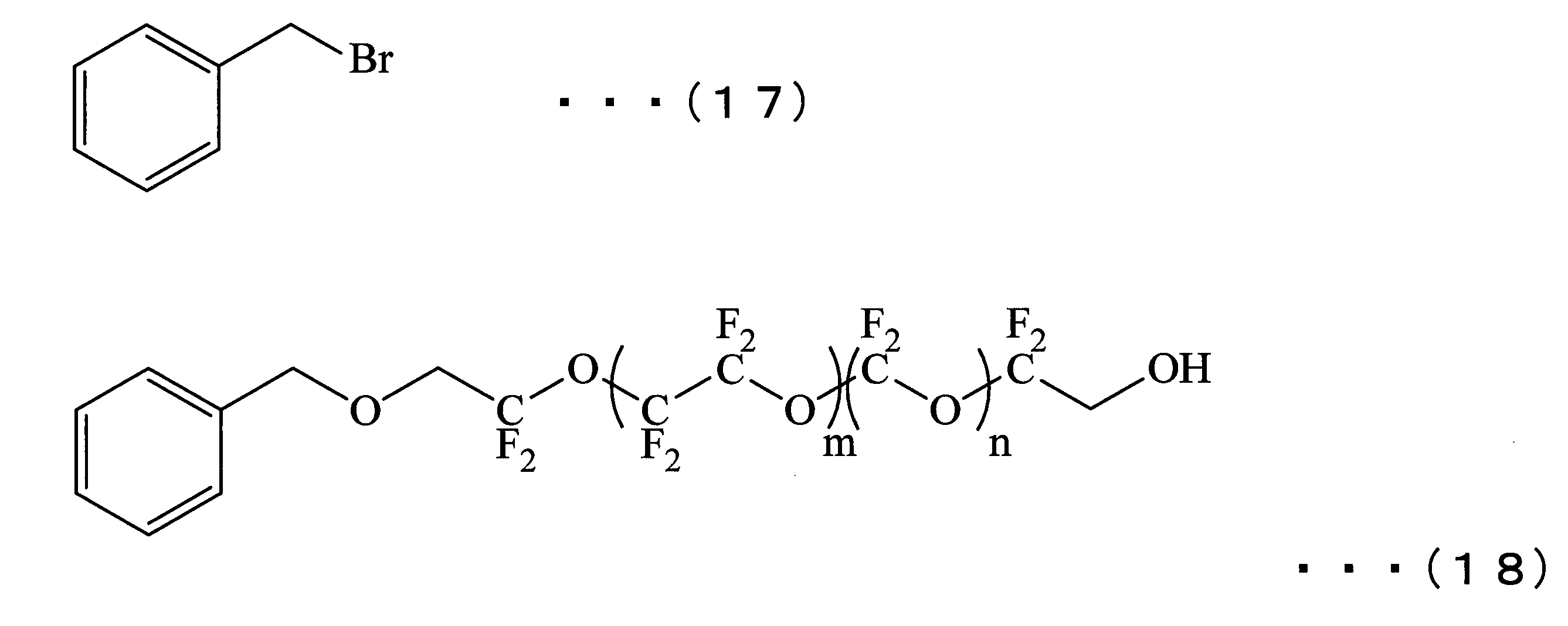
窒素ガス雰囲気下、500mLナスフラスコに、エチレングリコール12mLと、ジクロロメタン150mLと、トリチルクロライド20.0gとを仕込み、均一になるまで撹拌した。さらに上記ナスフラスコに、氷冷下で、トリエチルアミン20mL/ジクロロメタン50mL溶液を30分かけて加えた。さらに上記ナスフラスコに、室温で4-ジメチルアミノピリジン0.900gを加え、40℃で10時間反応させた。得られた反応生成物を25℃に冷却し、水洗し、無水硫酸ナトリウムによる脱水を行った。乾燥剤を濾別後、濾液を濃縮し、残渣をシリカゲルカラムクロマトグラフィーにて精製して、下記式(19)で示される化合物を19.0g得た。

窒素ガス雰囲気下、500mLナスフラスコに、化合物(19)を15.0g(49.3mmol)と、テトラヒドロフランを150mLと、アリルグリシジルエーテル7.00mLとを仕込み、均一になるまで撹拌した。この均一の液にt-BuOKを6.00g加え、70℃で4時間撹拌して反応させた。得られた反応生成物を25℃に冷却し、テトラヒドロフランを留去した。残渣にトルエンを加え、水洗し、無水硫酸ナトリウムによる脱水を行った。乾燥剤を濾別後、濾液を濃縮し、残渣をシリカゲルカラムクロマトグラフィーにて精製して、下記式(20)で示される化合物を12.0g得た。

300mLナスフラスコに、氷冷下で、式(20)で示される化合物5.00gと、ジクロロメタン50mLと、メタクロロ過安息香酸5.00gとを仕込み、同温で1時間、室温で12時間撹拌した。この反応液に氷冷下で、飽和亜硫酸ナトリウム水溶液10mLを加え、30分撹拌した後、室温で30分撹拌した。分液漏斗へ移液し、有機層を水洗し、無水硫酸ナトリウムによる脱水を行った。乾燥剤を濾別後、濾液を濃縮し、残渣をシリカゲルカラムクロマトグラフィーにて精製して、化合物(21)を4.50g得た。
得られた化合物(21)の1H-NMR測定を行い、以下の結果により構造を同定した。
化合物(21)1H-NMR(CDCl3);
δ[ppm]2.62(1H)、2.81(1H)、3.18(1H)、3.28(2H)、3.48(1H)、3.50~3.75(6H)、3.85(1H)、4.03(1H)、7.18~7.38(9H)、7.45(6H)
化合物(21)1H-NMR(CDCl3);
δ[ppm]2.62(1H)、2.81(1H)、3.18(1H)、3.28(2H)、3.48(1H)、3.50~3.75(6H)、3.85(1H)、4.03(1H)、7.18~7.38(9H)、7.45(6H)

窒素ガス雰囲気下、100mLナスフラスコに、上記で得られた式(18)で示される化合物5.98gと、式(21)で示される化合物1.52gと、t-BuOH30mLとを仕込み、室温で均一になるまで撹拌した。この均一の液にt-BuOKを0.200g(1.78mmol)加え、70℃で12時間撹拌して反応させた。得られた反応生成物を25℃に冷却し、0.1mol/Lの塩酸で中和した。その後、バートsdkちざいレルXFで抽出し、有機層を水洗して、無水硫酸ナトリウムによる脱水を行った。乾燥剤を濾別後、濾液を濃縮した。
得られた残渣に室温で、バートレルXF8mLと、水0.75mLと、トリフルオロ酢酸7.5mLとを加え、室温で1時間撹拌した。バートレルXF、水、トリフルオロ酢酸を35℃以下で留去し、得られた残渣に5%重曹水を30mL加え、バートレルXFで抽出し、有機層の水洗を行い、濃縮した。得られた残渣にメタノール5mLと、1mol/Lの水酸化ナトリウム水溶液14mLとを加え、室温で1時間撹拌した。メタノールを留去し、バートレルXFで抽出し、有機層を1mol/Lの塩酸と水で洗浄し、無水硫酸ナトリウムによる脱水を行った。乾燥剤を濾別後、濾液を濃縮し、残渣をシリカゲルカラムクロマトグラフィーにて精製し、化合物(I)を3.30g得た。
得られた化合物(I)の1H-NMR測定を行い、以下の結果により構造を同定した。
化合物(I);1H-NMR(C6F6/CD3COCD3=4/1(V/V));
δ[ppm]δ[ppm]3.45~3.90(14H)、3.95~4.15(4H)、4.90(2H)、7.45~7.75(5H)
化合物(I);1H-NMR(C6F6/CD3COCD3=4/1(V/V));
δ[ppm]δ[ppm]3.45~3.90(14H)、3.95~4.15(4H)、4.90(2H)、7.45~7.75(5H)
(実施例10)
式(17)で示される化合物の代わりに下記式(22)で示される化合物を4.42g用いたこと以外は、実施例9と同様な操作を行い、化合物(J)を3.40g得た。
式(17)で示される化合物の代わりに下記式(22)で示される化合物を4.42g用いたこと以外は、実施例9と同様な操作を行い、化合物(J)を3.40g得た。
得られた化合物(J)の1H-NMR測定を行い、以下の結果により構造を同定した。
化合物(J);1H-NMR(C6F6/CD3COCD3=4/1(V/V));
δ[ppm]3.45~3.90(14H)、3.95~4.15(4H)、4.95(2H)、7.45~7.75(7H)
化合物(J);1H-NMR(C6F6/CD3COCD3=4/1(V/V));
δ[ppm]3.45~3.90(14H)、3.95~4.15(4H)、4.95(2H)、7.45~7.75(7H)

(実施例11)
式(17)で示される化合物の代わりに下記式(23)で示される化合物を2.42g用いたこと以外は、実施例9と同様な操作を行い、化合物(K)を3.02g得た。
式(17)で示される化合物の代わりに下記式(23)で示される化合物を2.42g用いたこと以外は、実施例9と同様な操作を行い、化合物(K)を3.02g得た。
得られた化合物(K)の1H-NMR測定を行い、以下の結果により構造を同定した。
化合物(K);1H-NMR(C6F6/CD3COCD3=4/1(V/V));
δ[ppm]3.45~3.90(14H)、3.95~4.15(6H)、5.10~5.30(2H)、5.90~6.00(1H)
化合物(K);1H-NMR(C6F6/CD3COCD3=4/1(V/V));
δ[ppm]3.45~3.90(14H)、3.95~4.15(6H)、5.10~5.30(2H)、5.90~6.00(1H)
(実施例12)
窒素ガス雰囲気下、200mLナスフラスコに、上記で得られた式(8)で示される化合物4.90gと、t-BuOH45mLと、エピブロモヒドリン2.30gとを仕込み、均一になるまで撹拌した。この均一の液にt-BuOKを0.500g加え、70℃で6時間撹拌して反応させた。得られた反応生成物を25℃に冷却し、0.1mol/Lの塩酸で中和後、バートレルXFで抽出し、有機層を水洗し、無水硫酸ナトリウムによる脱水を行った。乾燥剤を濾別後、濾液を濃縮し、残渣をシリカゲルカラムクロマトグラフィーにて精製し、下記式(24)で示される化合物を5.00g得た。
窒素ガス雰囲気下、200mLナスフラスコに、上記で得られた式(8)で示される化合物4.90gと、t-BuOH45mLと、エピブロモヒドリン2.30gとを仕込み、均一になるまで撹拌した。この均一の液にt-BuOKを0.500g加え、70℃で6時間撹拌して反応させた。得られた反応生成物を25℃に冷却し、0.1mol/Lの塩酸で中和後、バートレルXFで抽出し、有機層を水洗し、無水硫酸ナトリウムによる脱水を行った。乾燥剤を濾別後、濾液を濃縮し、残渣をシリカゲルカラムクロマトグラフィーにて精製し、下記式(24)で示される化合物を5.00g得た。

窒素ガス雰囲気下、100mLナスフラスコに、式(24)で示される化合物3.19gと、t-BuOH28mLと、プロピレングリコール3.50gとを仕込み、均一になるまで撹拌した。この均一の液にt-BuOKを0.700g加え、70℃で6時間撹拌して反応させた。得られた反応生成物を25℃に冷却し、0.1mol/Lの塩酸で中和した後、バートレルXFで抽出し、有機層を水洗し、無水硫酸ナトリウムによる脱水を行った。乾燥剤を濾別後、濾液を濃縮し、残渣をシリカゲルカラムクロマトグラフィーにて精製し、化合物(L)を2.14g得た。
得られた化合物(L)の1H-NMR測定を行い、以下の結果により構造を同定した。
化合物(L);1H-NMR(C6F6/CD3COCD3=4/1(V/V));
δ[ppm]1.79(2H)、3.40~3.55(3H)、3.55~3.90(11H)、3.95~4.15(4H)、6.80~7.30(5H)
化合物(L);1H-NMR(C6F6/CD3COCD3=4/1(V/V));
δ[ppm]1.79(2H)、3.40~3.55(3H)、3.55~3.90(11H)、3.95~4.15(4H)、6.80~7.30(5H)
(実施例13)
式(8)で示される化合物の代わりに、実施例2の合成中間体である下記式(25)で示される化合物を5.00g用いたこと以外は、実施例12と同様な操作を行い、化合物(M)を2.34g得た。
式(8)で示される化合物の代わりに、実施例2の合成中間体である下記式(25)で示される化合物を5.00g用いたこと以外は、実施例12と同様な操作を行い、化合物(M)を2.34g得た。
得られた化合物(M)の1H-NMR測定を行い、以下の結果により構造を同定した。
化合物(M);1H-NMR(C6F6/CD3COCD3=4/1(V/V));
δ[ppm]1.79(2H)、3.45~3.60(3H)、3.60~4.00(14H)、3.95~4.15(4H)、6.75~6.85(2H)、7.10~7.20(2H)
化合物(M);1H-NMR(C6F6/CD3COCD3=4/1(V/V));
δ[ppm]1.79(2H)、3.45~3.60(3H)、3.60~4.00(14H)、3.95~4.15(4H)、6.75~6.85(2H)、7.10~7.20(2H)

(実施例14)
式(8)で示される化合物の代わりに、実施例4の合成中間体である下記式(26)で示される化合物を5.02g用いたこと以外は、実施例12と同様な操作を行い、化合物(N)を2.26g得た。
式(8)で示される化合物の代わりに、実施例4の合成中間体である下記式(26)で示される化合物を5.02g用いたこと以外は、実施例12と同様な操作を行い、化合物(N)を2.26g得た。
得られた化合物(N)の1H-NMR測定を行い、以下の結果により構造を同定した。
化合物(N);1H-NMR(C6F6/CD3COCD3=4/1(V/V));
δ[ppm]=1.79(2H)、3.15(2H)、3.40~3.55(8H)、3.60~3.95(8H)、4.00~4.15(4H)、6.80(2H)、7.05(1H)
化合物(N);1H-NMR(C6F6/CD3COCD3=4/1(V/V));
δ[ppm]=1.79(2H)、3.15(2H)、3.40~3.55(8H)、3.60~3.95(8H)、4.00~4.15(4H)、6.80(2H)、7.05(1H)

(実施例15)
式(8)で示される化合物の代わりに、実施例8の合成中間体である下記式(27)で示される化合物を4.77g用いたこと以外は、実施例12と同様な操作を行い、化合物(O)を2.33g得た。
式(8)で示される化合物の代わりに、実施例8の合成中間体である下記式(27)で示される化合物を4.77g用いたこと以外は、実施例12と同様な操作を行い、化合物(O)を2.33g得た。
得られた化合物(O)の1H-NMR測定を行い、以下の結果により構造を同定した。
化合物(O);1H-NMR(C6F6/CD3COCD3=4/1(V/V));
δ[ppm]1.79(2H)、3.45~3.90(14H)、3.95~4.15(6H)、5.10~5.30(2H)、5.90~6.00(1H)
化合物(O);1H-NMR(C6F6/CD3COCD3=4/1(V/V));
δ[ppm]1.79(2H)、3.45~3.90(14H)、3.95~4.15(6H)、5.10~5.30(2H)、5.90~6.00(1H)

(実施例16)
窒素ガス雰囲気下、100mLナスフラスコに、上記で得られた式(24)で示される化合物3.19gと、t-BuOH28mLと、2,2,3,3-テトラフルオロブタン-1,4-ジオール4.00gとを仕込み、均一になるまで撹拌した。この均一の液にt-BuOK0.112g加え、70℃で6時間撹拌して反応させた。得られた反応生成物を25℃に冷却し、0.1mol/Lの塩酸で中和した後、バートレルXFで抽出し、有機層を水洗し、無水硫酸ナトリウムによる脱水を行った。乾燥剤を濾別後、濾液を濃縮し、残渣をシリカゲルカラムクロマトグラフィーにて精製し、化合物(P)を2.32g得た。
窒素ガス雰囲気下、100mLナスフラスコに、上記で得られた式(24)で示される化合物3.19gと、t-BuOH28mLと、2,2,3,3-テトラフルオロブタン-1,4-ジオール4.00gとを仕込み、均一になるまで撹拌した。この均一の液にt-BuOK0.112g加え、70℃で6時間撹拌して反応させた。得られた反応生成物を25℃に冷却し、0.1mol/Lの塩酸で中和した後、バートレルXFで抽出し、有機層を水洗し、無水硫酸ナトリウムによる脱水を行った。乾燥剤を濾別後、濾液を濃縮し、残渣をシリカゲルカラムクロマトグラフィーにて精製し、化合物(P)を2.32g得た。
得られた化合物(P)の1H-NMR測定を行い、以下の結果により構造を同定した。
化合物(P);1H-NMR(C6F6/CD3COCD3=4/1(V/V));
δ[ppm]3.40~3.55(3H)、3.55~3.95(11H)、4.00~4.20(4H)、6.80~7.30(5H)
化合物(P);1H-NMR(C6F6/CD3COCD3=4/1(V/V));
δ[ppm]3.40~3.55(3H)、3.55~3.95(11H)、4.00~4.20(4H)、6.80~7.30(5H)
(実施例17)
式(24)で示される化合物の代わりに、実施例13の合成中間体である下記式(28)で示される化合物を3.26g用いたこと以外は、実施例16と同様な操作を行い、化合物(Q)を2.38g得た。
式(24)で示される化合物の代わりに、実施例13の合成中間体である下記式(28)で示される化合物を3.26g用いたこと以外は、実施例16と同様な操作を行い、化合物(Q)を2.38g得た。
得られた化合物(Q)の1H-NMR測定を行い、以下の結果により構造を同定した。
化合物(Q);1H-NMR(C6F6/CD3COCD3=4/1(V/V));
δ[ppm]3.45~3.60(3H)、3.60~4.00(14H)、4.00~4.20(4H)、6.75~6.85(2H)、7.10~7.20(2H)
化合物(Q);1H-NMR(C6F6/CD3COCD3=4/1(V/V));
δ[ppm]3.45~3.60(3H)、3.60~4.00(14H)、4.00~4.20(4H)、6.75~6.85(2H)、7.10~7.20(2H)

(実施例18)
式(24)で示される化合物の代わりに、実施例14の合成中間体である下記式(29)で示される化合物を3.26g用いたこと以外は、実施例16と同様な操作を行い、化合物(R)を2.21g得た。
式(24)で示される化合物の代わりに、実施例14の合成中間体である下記式(29)で示される化合物を3.26g用いたこと以外は、実施例16と同様な操作を行い、化合物(R)を2.21g得た。
得られた化合物(R)の1H-NMR測定を行い、以下の結果により構造を同定した。
化合物(R);1H-NMR(C6F6/CD3COCD3=4/1(V/V));
δ[ppm]=3.15(2H)、3.40~3.55(8H)、3.60~3.95(8H)、4.00~4.15(4H)、6.80(2H)、7.05(1H)
化合物(R);1H-NMR(C6F6/CD3COCD3=4/1(V/V));
δ[ppm]=3.15(2H)、3.40~3.55(8H)、3.60~3.95(8H)、4.00~4.15(4H)、6.80(2H)、7.05(1H)

(実施例19)
式(24)で示される化合物の代わりに、実施例15の合成中間体である下記式(30)で示される化合物を3.12g用いたこと以外は、実施例16と同様な操作を行い、化合物(S)を2.28g得た。
式(24)で示される化合物の代わりに、実施例15の合成中間体である下記式(30)で示される化合物を3.12g用いたこと以外は、実施例16と同様な操作を行い、化合物(S)を2.28g得た。
得られた化合物(S)の1H-NMR測定を行い、以下の結果により構造を同定した。
化合物(S);1H-NMR(C6F6/CD3COCD3=4/1(V/V)):
δ[ppm]=3.40~3.55(3H)、3.60~3.95(11H)、4.00~4.15(6H)、5.15(2H)、5.30(1H)、5.90~6.00(1H)
化合物(S);1H-NMR(C6F6/CD3COCD3=4/1(V/V)):
δ[ppm]=3.40~3.55(3H)、3.60~3.95(11H)、4.00~4.15(6H)、5.15(2H)、5.30(1H)、5.90~6.00(1H)

(実施例20)
500mLナスフラスコに、3-ブテニルアセテート(12.0g)と、ジクロロメタン100mLとを仕込み、室温で撹拌し、均一な溶液とした。この溶液に、氷冷下で、m-クロロ過安息香酸31.0gを加え、同温で1時間撹拌し、さらに室温で10時間撹拌した。その後、氷冷下で飽和炭酸水素ナトリウム水溶液20mLおよび、飽和亜硫酸ナトリウム水溶液20mLを加え、30分間同温で撹拌した。反応液から水層を分離し、有機層を水洗し、無水硫酸ナトリウムによる脱水を行った。乾燥剤を濾別後、濾液を濃縮し、残渣をシリカゲルカラムクロマトグラフィーにて精製し、化合物(31)を6.40g得た。
500mLナスフラスコに、3-ブテニルアセテート(12.0g)と、ジクロロメタン100mLとを仕込み、室温で撹拌し、均一な溶液とした。この溶液に、氷冷下で、m-クロロ過安息香酸31.0gを加え、同温で1時間撹拌し、さらに室温で10時間撹拌した。その後、氷冷下で飽和炭酸水素ナトリウム水溶液20mLおよび、飽和亜硫酸ナトリウム水溶液20mLを加え、30分間同温で撹拌した。反応液から水層を分離し、有機層を水洗し、無水硫酸ナトリウムによる脱水を行った。乾燥剤を濾別後、濾液を濃縮し、残渣をシリカゲルカラムクロマトグラフィーにて精製し、化合物(31)を6.40g得た。
得られた化合物(31)の1H-NMR測定を行い、以下の結果により構造を同定した。
化合物(31)1H-NMR(C6F6/CD3COCD3=4/1(V/V));
δ[ppm]1.73(1H)、1.88(1H)、2.01(3H)、2.41(1H)、2.67(1H)、2.88(1H)、4.12(2H)
化合物(31)1H-NMR(C6F6/CD3COCD3=4/1(V/V));
δ[ppm]1.73(1H)、1.88(1H)、2.01(3H)、2.41(1H)、2.67(1H)、2.88(1H)、4.12(2H)

窒素ガス雰囲気下、200mLナスフラスコに、式(8)で示される化合物7.10gと、式(31)で示される化合物0.781gと、t-BuOH50mLとを仕込み、室温で均一になるまで撹拌した。この均一の液にt-BuOKを0.225g加え、70℃で30時間撹拌して反応させた。得られた反応生成物を25℃に冷却し、0.1mol/Lの塩酸で中和した後、バートレルXFで抽出し、有機層を水洗し、無水硫酸ナトリウムによる脱水を行った。乾燥剤を濾別後、濾液を濃縮した。
得られた残渣に室温で、メタノール30mLと、1mol/Lの水酸化ナトリウム水溶液30mLとを加え、室温で1時間撹拌した。メタノールを留去し、バートレルXFで抽出し、有機層を水洗し、無水硫酸ナトリウムによる脱水を行った。乾燥剤を濾別後、濾液を濃縮し、残渣をシリカゲルカラムクロマトグラフィーにて精製し、化合物(T)を4.62g得た。
得られた残渣に室温で、メタノール30mLと、1mol/Lの水酸化ナトリウム水溶液30mLとを加え、室温で1時間撹拌した。メタノールを留去し、バートレルXFで抽出し、有機層を水洗し、無水硫酸ナトリウムによる脱水を行った。乾燥剤を濾別後、濾液を濃縮し、残渣をシリカゲルカラムクロマトグラフィーにて精製し、化合物(T)を4.62g得た。
得られた化合物(T)の1H-NMR測定を行い、以下の結果により構造を同定した。
化合物(T);1H-NMR(C6F6/CD3COCD3=4/1(V/V));
δ[ppm]1.54~1.76(2H)、3.55~3.80(5H)、3.82~4.20(9H)、6.80~7.30(5H)
化合物(T);1H-NMR(C6F6/CD3COCD3=4/1(V/V));
δ[ppm]1.54~1.76(2H)、3.55~3.80(5H)、3.82~4.20(9H)、6.80~7.30(5H)
(実施例21)
式(8)で示される化合物の代わりに、式(25)で示される化合物を7.25g用いたこと以外は、実施例20と同様な操作を行い、化合物(U)を5.02g得た。
式(8)で示される化合物の代わりに、式(25)で示される化合物を7.25g用いたこと以外は、実施例20と同様な操作を行い、化合物(U)を5.02g得た。
得られた化合物(U)の1H-NMR測定を行い、以下の結果により構造を同定した。
化合物(U);1H-NMR(C6F6/CD3COCD3=4/1(V/V));
δ[ppm]1.54~1.76(2H)、3.55~3.80(8H)、3.82~4.20(9H)、6.55~6.60(2H)、6.70~6.75(2H)
化合物(U);1H-NMR(C6F6/CD3COCD3=4/1(V/V));
δ[ppm]1.54~1.76(2H)、3.55~3.80(8H)、3.82~4.20(9H)、6.55~6.60(2H)、6.70~6.75(2H)
(実施例22)
式(8)で示される化合物の代わりに、実施例10の中間体である下記式(32)で示される化合物を7.35g用いたこと以外は、実施例20と同様な操作を行い、化合物(V)を4.89g得た。
式(8)で示される化合物の代わりに、実施例10の中間体である下記式(32)で示される化合物を7.35g用いたこと以外は、実施例20と同様な操作を行い、化合物(V)を4.89g得た。
得られた化合物(V)の1H-NMR測定を行い、以下の結果により構造を同定した。
化合物(V);1H-NMR(C6F6/CD3COCD3=4/1(V/V));
δ[ppm]1.54~1.76(2H)、3.55~3.80(5H)、3.82~4.20(9H)、7.00~7.50(7H)
化合物(V);1H-NMR(C6F6/CD3COCD3=4/1(V/V));
δ[ppm]1.54~1.76(2H)、3.55~3.80(5H)、3.82~4.20(9H)、7.00~7.50(7H)

(実施例23)
式(8)で示される化合物の代わりに、式(26)で示される化合物を7.27g用いたこと以外は、実施例20と同様な操作を行い、化合物(W)を4.55g得た。
式(8)で示される化合物の代わりに、式(26)で示される化合物を7.27g用いたこと以外は、実施例20と同様な操作を行い、化合物(W)を4.55g得た。
得られた化合物(W)の1H-NMR測定を行い、以下の結果により構造を同定した。
化合物(W);1H-NMR(C6F6/CD3COCD3=4/1(V/V));
δ[ppm]1.54~1.76(2H)、3.55~3.80(5H)、3.80~4.20(9H)、6.80(2H)、7.05(1H)
化合物(W);1H-NMR(C6F6/CD3COCD3=4/1(V/V));
δ[ppm]1.54~1.76(2H)、3.55~3.80(5H)、3.80~4.20(9H)、6.80(2H)、7.05(1H)
(実施例24)
式(8)で示される化合物の代わりに、実施例6の中間体である下記式(33)で示される化合物を7.35g用いたこと以外は、実施例20と同様な操作を行い、化合物(X)を4.24g得た。
式(8)で示される化合物の代わりに、実施例6の中間体である下記式(33)で示される化合物を7.35g用いたこと以外は、実施例20と同様な操作を行い、化合物(X)を4.24g得た。
得られた化合物(X)の1H-NMR測定を行い、以下の結果により構造を同定した。
化合物(X);1H-NMR(C6F6/CD3COCD3=4/1(V/V));
δ[ppm]1.54~1.76(2H)、2.35(3H)、3.00(2H)、3.55~3.80(5H)、3.82~4.20(11H)、8.40(1H)
化合物(X);1H-NMR(C6F6/CD3COCD3=4/1(V/V));
δ[ppm]1.54~1.76(2H)、2.35(3H)、3.00(2H)、3.55~3.80(5H)、3.82~4.20(11H)、8.40(1H)

(実施例25)
式(8)で示される化合物の代わりに、式(27)で示される化合物を6.92g用いたこと以外は、実施例20と同様な操作を行い、化合物(Y)を4.66g得た。
式(8)で示される化合物の代わりに、式(27)で示される化合物を6.92g用いたこと以外は、実施例20と同様な操作を行い、化合物(Y)を4.66g得た。
得られた化合物(Y)の1H-NMR測定を行い、以下の結果により構造を同定した。
化合物(Y);1H-NMR(C6F6/CD3COCD3=4/1(V/V));
δ[ppm]1.54~1.76(2H)、3.55~3.80(5H)、3.82~4.20(11H)、5.20~5.30(2H)、5.80~5.90(1H)
化合物(Y);1H-NMR(C6F6/CD3COCD3=4/1(V/V));
δ[ppm]1.54~1.76(2H)、3.55~3.80(5H)、3.82~4.20(11H)、5.20~5.30(2H)、5.80~5.90(1H)
(実施例26)
窒素ガス雰囲気下、200mLナスフラスコに、HOCH2CF2O(CF2CF2O)xCF2CH2OH(式中のxは8である。)で表される化合物(数平均分子量1106、分子量分布1.1)22.1gと、化合物(7)1.50gと、t-BuOH10mLとを仕込み、室温で均一になるまで撹拌した。この均一の液にt-BuOKを0.900g加え、70℃で8時間撹拌して反応させた。得られた反応生成物を25℃に冷却し、0.5mol/Lの塩酸で中和した後、バートレルXFで抽出し、有機層を水洗し、無水硫酸ナトリウムによる脱水を行った。乾燥剤を濾別後、濾液を濃縮し、残渣をシリカゲルカラムクロマトグラフィーにて精製して、化合物(34)を6.29g得た。
窒素ガス雰囲気下、200mLナスフラスコに、HOCH2CF2O(CF2CF2O)xCF2CH2OH(式中のxは8である。)で表される化合物(数平均分子量1106、分子量分布1.1)22.1gと、化合物(7)1.50gと、t-BuOH10mLとを仕込み、室温で均一になるまで撹拌した。この均一の液にt-BuOKを0.900g加え、70℃で8時間撹拌して反応させた。得られた反応生成物を25℃に冷却し、0.5mol/Lの塩酸で中和した後、バートレルXFで抽出し、有機層を水洗し、無水硫酸ナトリウムによる脱水を行った。乾燥剤を濾別後、濾液を濃縮し、残渣をシリカゲルカラムクロマトグラフィーにて精製して、化合物(34)を6.29g得た。

窒素ガス雰囲気下、200mLナスフラスコに、上記で得られた式(34)で示される化合物6.28gと、式(9)で示される化合物1.05gと、t-BuOH50mLとを仕込み、室温で均一になるまで撹拌した。この均一の液に、t-BuOKを0.224g加え、70℃で16時間撹拌して反応させた。得られた反応生成物を25℃に冷却し、0.1mol/Lの塩酸で中和した後、バートレルXFで抽出し、有機層を水洗し、無水硫酸ナトリウムによる脱水を行った。乾燥剤を濾別後、濾液を濃縮した。
得られた残渣に室温で、水0.75mLと、トリフルオロ酢酸7.5mLとを加え、室温で6時間撹拌した。水、トリフルオロ酢酸を35℃以下で留去し、得られた残渣に5%重曹水を30mL加え、バートレルXFで抽出し、有機層を水洗し、濃縮した。得られた残渣にメタノール5mLと1mol/Lの水酸化ナトリウム水溶液20mLとを加え、室温で1時間撹拌した。メタノールを留去し、バートレルXFで抽出し、有機層を水洗し、無水硫酸ナトリウムによる脱水を行った。乾燥剤を濾別後、濾液を濃縮し、残渣をシリカゲルカラムクロマトグラフィーにて精製し、化合物(Z)を4.28g得た。
得られた化合物(Z)の1H-NMR測定を行い、以下の結果により構造を同定した。
化合物(Z);1H-NMR(C6F6/CD3COCD3=4/1(V/V));
δ[ppm]3.40~3.55(3H)、3.88~4.20(15H)、6.90~7.20(5H)
化合物(Z);1H-NMR(C6F6/CD3COCD3=4/1(V/V));
δ[ppm]3.40~3.55(3H)、3.88~4.20(15H)、6.90~7.20(5H)
(実施例27)
式(7)で示される化合物の代わりに、下記式(35)で示される化合物を1.12g用いたこと以外は、実施例1と同様な操作を行い、化合物(AB)を4.05g得た。
式(7)で示される化合物の代わりに、下記式(35)で示される化合物を1.12g用いたこと以外は、実施例1と同様な操作を行い、化合物(AB)を4.05g得た。
得られた化合物(AB)の1H-NMR測定を行い、以下の結果により構造を同定した。
化合物(AB);1H-NMR(CD3COCD3);
δ[ppm]2.50(1H)、3.45~3.65(8H)、3.65~3.90(6H)、4.00~4.20(6H)
化合物(AB);1H-NMR(CD3COCD3);
δ[ppm]2.50(1H)、3.45~3.65(8H)、3.65~3.90(6H)、4.00~4.20(6H)

(実施例28)
式(7)で示される化合物の代わりに、下記式(36)で示される化合物を1.88g用いたこと以外は、実施例1と同様な操作を行い、化合物(AC)を3.85g得た。なお、下記式(36)で示される化合物は、グリセリンジアリルエーテルを片側だけ酸化して合成した。
式(7)で示される化合物の代わりに、下記式(36)で示される化合物を1.88g用いたこと以外は、実施例1と同様な操作を行い、化合物(AC)を3.85g得た。なお、下記式(36)で示される化合物は、グリセリンジアリルエーテルを片側だけ酸化して合成した。
得られた化合物(AC)の1H-NMR測定を行い、以下の結果により構造を同定した。
化合物(AC);1H-NMR(CD3COCD3);
δ[ppm]3.35~3.95(19H)、3.95~4.15(6H)、5.05~5.15(1H)、5.20~5.30(1H)、5.80~6.00(1H)
化合物(AC);1H-NMR(CD3COCD3);
δ[ppm]3.35~3.95(19H)、3.95~4.15(6H)、5.05~5.15(1H)、5.20~5.30(1H)、5.80~6.00(1H)

「比較例1」
下記式(AA)で表される化合物を特許文献1に記載の方法で合成した。
下記式(AA)で表される化合物を特許文献1に記載の方法で合成した。

「比較例2」
下記式(BB)で表される化合物を特許文献2に記載の方法で合成した。
下記式(BB)で表される化合物を特許文献2に記載の方法で合成した。

「比較例3」
下記式(CC)で表される化合物を特許文献3に記載の方法で合成した。
下記式(CC)で表される化合物を特許文献3に記載の方法で合成した。

このようにして得られた実施例1~28および比較例1~3の化合物を、式(1)に当てはめたときのR1~R4の構造を表1~表4に示す。また、実施例1~26および比較例1~3の化合物の数平均分子量を、上述した1H-NMRおよび19F-NMRの測定により求めた。その結果を表1~表4に示す。


次に、以下に示す方法により、実施例1~28および比較例1~3で得られた化合物を用いて潤滑層形成用溶液を調製した。そして、得られた潤滑層形成用溶液を用いて、以下に示す方法により、磁気記録媒体の潤滑層を形成し、実施例1~28および比較例1~3の磁気記録媒体を得た。
「潤滑層形成用溶液」
実施例1~28および比較例1~3で得られた化合物を、それぞれフッ素系溶媒であるバートレル(登録商標)XF(商品名、三井デュポンフロロケミカル社製)に溶解し、保護層上に塗布した時の膜厚が9Å~11Åになるようにバートレルで希釈し、化合物の濃度が0.0005質量%~0.001質量%である潤滑層形成用溶液とした。
実施例1~28および比較例1~3で得られた化合物を、それぞれフッ素系溶媒であるバートレル(登録商標)XF(商品名、三井デュポンフロロケミカル社製)に溶解し、保護層上に塗布した時の膜厚が9Å~11Åになるようにバートレルで希釈し、化合物の濃度が0.0005質量%~0.001質量%である潤滑層形成用溶液とした。
「磁気記録媒体」
直径65mmの基板上に、付着層と軟磁性層と第1下地層と第2下地層と磁性層と保護層とを順次設けた磁気記録媒体を用意した。保護層は、炭素からなるものとした。
保護層までの各層の形成された磁気記録媒体の保護層上に、実施例1~28および比較例1~3の潤滑層形成用溶液を、それぞれディップ法により塗布した。なお、ディップ法は、浸漬速度10mm/sec、浸漬時間30sec、引き上げ速度1.2mm/secの条件で行った。
その後、潤滑層形成用溶液を塗布した磁気記録媒体を、120℃の恒温槽に入れ、10分間加熱して潤滑層形成用溶液中の溶媒を除去することにより、保護層上に潤滑層を形成し、磁気記録媒体を得た。
直径65mmの基板上に、付着層と軟磁性層と第1下地層と第2下地層と磁性層と保護層とを順次設けた磁気記録媒体を用意した。保護層は、炭素からなるものとした。
保護層までの各層の形成された磁気記録媒体の保護層上に、実施例1~28および比較例1~3の潤滑層形成用溶液を、それぞれディップ法により塗布した。なお、ディップ法は、浸漬速度10mm/sec、浸漬時間30sec、引き上げ速度1.2mm/secの条件で行った。
その後、潤滑層形成用溶液を塗布した磁気記録媒体を、120℃の恒温槽に入れ、10分間加熱して潤滑層形成用溶液中の溶媒を除去することにより、保護層上に潤滑層を形成し、磁気記録媒体を得た。
このようにして得られた実施例1~28および比較例1~3の磁気記録媒体の有する潤滑層の膜厚を、FT-IR(商品名:Nicolet iS50、Thermo Fisher Scientific社製)を用いて測定した。その結果を表5に示す。
次に、実施例1~28および比較例1~3の磁気記録媒体に対して、以下に示す化学物質耐性試験を行なった。
(化学物質耐性試験)
この評価手法は、高温環境下において汚染物質を生成させる環境物質による磁気記録媒体の汚染を調べる評価手法である。以下に示す耐環境性の評価手法では、環境物質としてSiイオンを用い、環境物質によって生成された磁気記録媒体を汚染する汚染物質の量としてSi吸着量を測定した。
(化学物質耐性試験)
この評価手法は、高温環境下において汚染物質を生成させる環境物質による磁気記録媒体の汚染を調べる評価手法である。以下に示す耐環境性の評価手法では、環境物質としてSiイオンを用い、環境物質によって生成された磁気記録媒体を汚染する汚染物質の量としてSi吸着量を測定した。
具体的には、評価対象である磁気記録媒体を、温度85℃、湿度0%の高温環境下で、シロキサン系Siゴムの存在下に240時間保持した。次に、磁気記録媒体の表面に存在するSi吸着量を、二次イオン質量分析法(SIMS)を用いて分析測定し、Siイオンによる汚染の程度をSi吸着量として評価した。Si吸着量の評価は、比較例2の結果を1.00としたときの数値を用いて評価した。その結果を表5に示す。

表5より、実施例1~28の磁気記録媒体では、比較例1~3の磁気記録媒体と比較して、潤滑層の膜厚が薄いにも関わらず、Si吸着量が少なく、高温環境下において環境物質によって汚染されにくいことが明らかになった。
また、実施例2は、潤滑層を形成している式(1)で表される化合物中のR4における水酸基の結合している炭素原子同士が、水酸基の結合していない炭素原子を含む連結基を介して結合している場合である。これに対し、比較例2は、潤滑層を形成している式(1)で表される化合物中のR4における水酸基の結合している炭素原子同士が結合している場合である。表5に示す実施例2と比較例2の結果から、R4における水酸基の結合している炭素原子同士が、水酸基の結合していない炭素原子を含む連結基を介して結合していることにより、化学物質耐性が向上することが分かる。
また、実施例2は、潤滑層を形成している式(1)で表される化合物中のR4における水酸基の結合している炭素原子同士が、水酸基の結合していない炭素原子を含む連結基を介して結合している場合である。これに対し、比較例2は、潤滑層を形成している式(1)で表される化合物中のR4における水酸基の結合している炭素原子同士が結合している場合である。表5に示す実施例2と比較例2の結果から、R4における水酸基の結合している炭素原子同士が、水酸基の結合していない炭素原子を含む連結基を介して結合していることにより、化学物質耐性が向上することが分かる。
また、実施例1~28および比較例1~3の磁気記録媒体に対して、以下に示す耐摩耗性試験を行なった。
(耐摩耗性試験)
ピンオンディスク型摩擦摩耗試験機を用い、接触子としての直径2mmのアルミナの球を、荷重40gf、摺動速度0.25m/secで、磁気記録媒体の潤滑層上で摺動させ、潤滑層の表面の摩擦係数を測定した。そして、潤滑層の表面の摩擦係数が急激に増大するまでの摺動時間を測定した。摩擦係数が急激に増大するまでの摺動時間は、各磁気記録媒体の潤滑層について4回ずつ測定し、その平均値(時間)を潤滑剤塗膜の耐摩耗性の指標とした。実施例1~28の化合物および比較例1~3の化合物を用いた磁気記録媒体の結果を表5に示す。摩擦係数増大時間の評価は、以下のとおりとした。
◎:650sec以上
○:550sec以上、650sec未満
△:450sec以上、550sec未満
×:450sec未満
なお、摩擦係数が急激に増大するまでの時間は、以下に示す理由により、潤滑層の耐摩耗性の指標として用いることができる。磁気記録媒体の潤滑層は、磁気記録媒体を使用することにより摩耗が進行し、摩耗により潤滑層が無くなると、接触子と保護層とが直接接触して、摩擦係数が急激に増大するためである。本摩擦係数が急激に増大するまでの時間は、フリクション試験とも相間があると考えられる。
表5に示すように、実施例1~28の磁気記録媒体は、比較例1~3の磁気記録媒体と比較して、潤滑層の膜厚が薄いにも関わらず、摩擦係数が急激に増大するまでの摺動時間が長く、耐摩耗性が良好であった。
これは、実施例1~28の磁気記録媒体では、潤滑層を形成している式(1)で表される化合物中のR1が、二重結合または三重結合を少なくとも一つ有する有機基を含む末端基であることよるものであると推定される。
これは、実施例1~28の磁気記録媒体では、潤滑層を形成している式(1)で表される化合物中のR1が、二重結合または三重結合を少なくとも一つ有する有機基を含む末端基であることよるものであると推定される。
本発明の含フッ素エーテル化合物を含む磁気記録媒体用潤滑剤を用いることにより、厚みが薄くても、優れた化学物質耐性および耐摩耗性を実現できる潤滑層を形成できる。
10・・・磁気記録媒体、11・・・基板、12・・・付着層、13・・・軟磁性層、14・・・第1下地層、15・・・第2下地層、16・・・磁性層、17・・・保護層、18・・・潤滑層。
Claims (12)
- 下記式(1)で表されることを特徴とする含フッ素エーテル化合物。
R1-R2-CH2-R3-CH2-R4 (1)
(式(1)中、R1は二重結合または三重結合を少なくとも一つ有する有機基を含む末端基であり、R2はエーテル性酸素によってR1と結合する2価の連結基であり、R3はパーフルオロポリエーテル鎖であり、R4は2つまたは3つの極性基を含み、各極性基がそれぞれ異なる炭素原子に結合し、前記極性基の結合している炭素原子同士が、極性基の結合していない炭素原子を含む連結基を介して結合している末端基である。) - 前記式(1)におけるR4の極性基が水酸基である請求項1に記載の含フッ素エーテル化合物。
- 前記式(1)におけるR4は下記式(2-1)~(2-4)のいずれかの末端基である請求項1または請求項2に記載の含フッ素エーテル化合物。


- 前記式(1)におけるR3が、下記式(3)で表されることを特徴とする請求項1~請求項3のいずれか一項に記載の含フッ素エーテル化合物。

- 前記式(1)におけるR3が、下記式(4)または下記式(5)で表されることを特徴とする請求項1~請求項3のいずれか一項に記載の含フッ素エーテル化合物。


- 前記式(1)におけるR1が、芳香族環を含む末端基、複素環を含む末端基、アルケニル基を含む末端基、アルキニル基を含む末端基のいずれかであることを特徴とする[1]~[5]のいずれかに記載の含フッ素エーテル化合物。
- 前記式(1)におけるR2が、-O-または下記式(6)で表されることを特徴とする請求項1~請求項6のいずれか一項に記載の含フッ素エーテル化合物。

- 前記式(1)におけるR4が、3つの極性基を含むことを特徴とする請求項1~請求項7のいずれか一項に記載の含フッ素エーテル化合物。
- 数平均分子量が500~10000の範囲内である請求項1~請求項8のいずれか一項に記載の含フッ素エーテル化合物。
- 請求項1~請求項9のいずれか一項に記載の含フッ素エーテル化合物を含むことを特徴とする磁気記録媒体用潤滑剤。
- 基板上に、少なくとも磁性層と、保護層と、潤滑層とが順次設けられた磁気記録媒体であって、前記潤滑層が、請求項1~請求項9のいずれか一項に記載の含フッ素エーテル化合物を含むことを特徴とする磁気記録媒体。
- 前記潤滑層の平均膜厚が、0.5nm~3nmである請求項11に記載の磁気記録媒体。
Priority Applications (3)
| Application Number | Priority Date | Filing Date | Title |
|---|---|---|---|
| CN201780012469.9A CN108698968B (zh) | 2016-03-10 | 2017-01-30 | 含氟醚化合物、磁记录介质用润滑剂及磁记录介质 |
| JP2018504048A JP6763014B2 (ja) | 2016-03-10 | 2017-01-30 | 含フッ素エーテル化合物、磁気記録媒体用潤滑剤および磁気記録媒体 |
| US16/082,349 US11279664B2 (en) | 2016-03-10 | 2017-01-30 | Fluorine-containing ether compound, lubricant for magnetic recording medium, and magnetic recording medium |
Applications Claiming Priority (2)
| Application Number | Priority Date | Filing Date | Title |
|---|---|---|---|
| JP2016-047359 | 2016-03-10 | ||
| JP2016047359 | 2016-03-10 |
Publications (1)
| Publication Number | Publication Date |
|---|---|
| WO2017154403A1 true WO2017154403A1 (ja) | 2017-09-14 |
Family
ID=59790376
Family Applications (1)
| Application Number | Title | Priority Date | Filing Date |
|---|---|---|---|
| PCT/JP2017/003165 WO2017154403A1 (ja) | 2016-03-10 | 2017-01-30 | 含フッ素エーテル化合物、磁気記録媒体用潤滑剤および磁気記録媒体 |
Country Status (4)
| Country | Link |
|---|---|
| US (1) | US11279664B2 (ja) |
| JP (2) | JP6763014B2 (ja) |
| CN (1) | CN108698968B (ja) |
| WO (1) | WO2017154403A1 (ja) |
Cited By (11)
| Publication number | Priority date | Publication date | Assignee | Title |
|---|---|---|---|---|
| WO2019087548A1 (ja) * | 2017-10-31 | 2019-05-09 | 昭和電工株式会社 | 含フッ素エーテル化合物、磁気記録媒体用潤滑剤および磁気記録媒体 |
| WO2020054420A1 (ja) * | 2018-09-12 | 2020-03-19 | 昭和電工株式会社 | 含フッ素エーテル化合物、磁気記録媒体用潤滑剤および磁気記録媒体 |
| WO2020054419A1 (ja) * | 2018-09-12 | 2020-03-19 | 昭和電工株式会社 | 含フッ素エーテル化合物、磁気記録媒体用潤滑剤および磁気記録媒体 |
| WO2020184653A1 (ja) * | 2019-03-12 | 2020-09-17 | 昭和電工株式会社 | 含フッ素エーテル化合物、磁気記録媒体用潤滑剤および磁気記録媒体 |
| WO2020250627A1 (ja) * | 2019-06-10 | 2020-12-17 | 株式会社Moresco | パーフルオロポリエーテル化合物、潤滑剤および磁気ディスク |
| WO2021054202A1 (ja) * | 2019-09-18 | 2021-03-25 | 昭和電工株式会社 | 含フッ素エーテル化合物、磁気記録媒体用潤滑剤および磁気記録媒体 |
| WO2021065380A1 (ja) * | 2019-10-01 | 2021-04-08 | 昭和電工株式会社 | 含フッ素エーテル化合物、磁気記録媒体用潤滑剤および磁気記録媒体 |
| WO2023033044A1 (ja) * | 2021-09-02 | 2023-03-09 | 株式会社レゾナック | 含フッ素エーテル化合物、磁気記録媒体用潤滑剤および磁気記録媒体 |
| US11820862B2 (en) | 2017-06-30 | 2023-11-21 | Resonac Corporation | Organic fluorine compound, lubricant, and processing method of magnetic recording medium |
| WO2023224095A1 (ja) * | 2022-05-20 | 2023-11-23 | 株式会社レゾナック | 含フッ素エーテル化合物、磁気記録媒体用潤滑剤および磁気記録媒体 |
| US11905365B2 (en) | 2019-12-26 | 2024-02-20 | Resonac Corporation | Fluorine-containing ether compound, lubricant for magnetic recording medium, and magnetic recording medium |
Families Citing this family (8)
| Publication number | Priority date | Publication date | Assignee | Title |
|---|---|---|---|---|
| US11261394B2 (en) * | 2017-09-13 | 2022-03-01 | Showa Denko K.K. | Fluorine-containing ether compound, lubricant for magnetic recording media, and magnetic recording medium |
| JP7165206B2 (ja) * | 2018-12-06 | 2022-11-02 | 株式会社Moresco | フルオロポリエーテル化合物、潤滑剤および磁気ディスク |
| WO2021020076A1 (ja) * | 2019-07-31 | 2021-02-04 | 昭和電工株式会社 | 含フッ素エーテル化合物、磁気記録媒体用潤滑剤および磁気記録媒体 |
| US11919875B2 (en) | 2019-09-30 | 2024-03-05 | Resonac Corporation | Fluorine-containing ether compound, lubricant for magnetic recording medium, and magnetic recording medium |
| JPWO2021131993A1 (ja) * | 2019-12-23 | 2021-07-01 | ||
| US20230115042A1 (en) * | 2020-02-07 | 2023-04-13 | Showa Denko K.K. | Fluorine-containing ether compound, lubricant for magnetic recording medium, and magnetic recording medium |
| CN115667196B (zh) * | 2020-06-11 | 2024-03-15 | 株式会社力森诺科 | 含氟醚化合物、磁记录介质用润滑剂及磁记录介质 |
| CN116096782A (zh) * | 2020-08-20 | 2023-05-09 | 株式会社力森诺科 | 含氟醚化合物、磁记录介质用润滑剂及磁记录介质 |
Citations (6)
| Publication number | Priority date | Publication date | Assignee | Title |
|---|---|---|---|---|
| JP2004346318A (ja) * | 2003-05-20 | 2004-12-09 | Solvay Solexis Spa | ペルフルオロポリエーテル添加剤 |
| WO2006011387A1 (ja) * | 2004-07-27 | 2006-02-02 | Asahi Glass Company, Limited | 含フッ素ポリエーテル化合物を潤滑剤とする磁気記録媒体用潤滑剤溶液 |
| WO2009123043A1 (ja) * | 2008-03-30 | 2009-10-08 | Hoya株式会社 | 磁気ディスク及びその製造方法 |
| JP2012009090A (ja) * | 2010-06-22 | 2012-01-12 | Wd Media (Singapore) Pte. Ltd | 磁気ディスクの製造方法 |
| JP2013163667A (ja) * | 2012-02-13 | 2013-08-22 | Moresco Corp | フルオロポリエーテル化合物、これを含有する潤滑剤ならびに磁気ディスク |
| WO2015087615A1 (ja) * | 2013-12-09 | 2015-06-18 | 株式会社Moresco | フルオロポリエーテル化合物、これを含有する潤滑剤ならびに磁気ディスク |
Family Cites Families (5)
| Publication number | Priority date | Publication date | Assignee | Title |
|---|---|---|---|---|
| JP5250937B2 (ja) * | 2006-02-28 | 2013-07-31 | 富士通株式会社 | 潤滑剤、磁気記録媒体およびヘッドスライダ |
| JP4632144B2 (ja) | 2007-09-14 | 2011-02-16 | 富士電機デバイステクノロジー株式会社 | 磁気記録媒体 |
| JP5613916B2 (ja) | 2008-12-18 | 2014-10-29 | 株式会社Moresco | パーフルオロポリエーテル化合物、その製造方法、該化合物を含有する潤滑剤、および磁気ディスク |
| JP6838874B2 (ja) * | 2016-07-05 | 2021-03-03 | 昭和電工株式会社 | 含フッ素エーテル化合物、磁気記録媒体用潤滑剤および磁気記録媒体 |
| JP6804893B2 (ja) * | 2016-08-10 | 2020-12-23 | 昭和電工株式会社 | 含フッ素エーテル化合物、磁気記録媒体用潤滑剤および磁気記録媒体 |
-
2017
- 2017-01-30 US US16/082,349 patent/US11279664B2/en active Active
- 2017-01-30 WO PCT/JP2017/003165 patent/WO2017154403A1/ja active Application Filing
- 2017-01-30 JP JP2018504048A patent/JP6763014B2/ja active Active
- 2017-01-30 CN CN201780012469.9A patent/CN108698968B/zh active Active
-
2020
- 2020-07-30 JP JP2020129365A patent/JP7016923B2/ja active Active
Patent Citations (6)
| Publication number | Priority date | Publication date | Assignee | Title |
|---|---|---|---|---|
| JP2004346318A (ja) * | 2003-05-20 | 2004-12-09 | Solvay Solexis Spa | ペルフルオロポリエーテル添加剤 |
| WO2006011387A1 (ja) * | 2004-07-27 | 2006-02-02 | Asahi Glass Company, Limited | 含フッ素ポリエーテル化合物を潤滑剤とする磁気記録媒体用潤滑剤溶液 |
| WO2009123043A1 (ja) * | 2008-03-30 | 2009-10-08 | Hoya株式会社 | 磁気ディスク及びその製造方法 |
| JP2012009090A (ja) * | 2010-06-22 | 2012-01-12 | Wd Media (Singapore) Pte. Ltd | 磁気ディスクの製造方法 |
| JP2013163667A (ja) * | 2012-02-13 | 2013-08-22 | Moresco Corp | フルオロポリエーテル化合物、これを含有する潤滑剤ならびに磁気ディスク |
| WO2015087615A1 (ja) * | 2013-12-09 | 2015-06-18 | 株式会社Moresco | フルオロポリエーテル化合物、これを含有する潤滑剤ならびに磁気ディスク |
Cited By (29)
| Publication number | Priority date | Publication date | Assignee | Title |
|---|---|---|---|---|
| US11820862B2 (en) | 2017-06-30 | 2023-11-21 | Resonac Corporation | Organic fluorine compound, lubricant, and processing method of magnetic recording medium |
| JPWO2019087548A1 (ja) * | 2017-10-31 | 2020-09-24 | 昭和電工株式会社 | 含フッ素エーテル化合物、磁気記録媒体用潤滑剤および磁気記録媒体 |
| US11180457B2 (en) | 2017-10-31 | 2021-11-23 | Showa Denko K. K. | Fluorine-containing ether compound, lubricant for magnetic recording medium, and magnetic recording medium |
| WO2019087548A1 (ja) * | 2017-10-31 | 2019-05-09 | 昭和電工株式会社 | 含フッ素エーテル化合物、磁気記録媒体用潤滑剤および磁気記録媒体 |
| JP7177782B2 (ja) | 2017-10-31 | 2022-11-24 | 昭和電工株式会社 | 含フッ素エーテル化合物、磁気記録媒体用潤滑剤および磁気記録媒体 |
| CN112672999B (zh) * | 2018-09-12 | 2024-01-12 | 株式会社力森诺科 | 含氟醚化合物、磁记录介质用润滑剂及磁记录介质 |
| WO2020054419A1 (ja) * | 2018-09-12 | 2020-03-19 | 昭和電工株式会社 | 含フッ素エーテル化合物、磁気記録媒体用潤滑剤および磁気記録媒体 |
| JPWO2020054419A1 (ja) * | 2018-09-12 | 2021-09-24 | 昭和電工株式会社 | 含フッ素エーテル化合物、磁気記録媒体用潤滑剤および磁気記録媒体 |
| WO2020054420A1 (ja) * | 2018-09-12 | 2020-03-19 | 昭和電工株式会社 | 含フッ素エーテル化合物、磁気記録媒体用潤滑剤および磁気記録媒体 |
| CN112672999A (zh) * | 2018-09-12 | 2021-04-16 | 昭和电工株式会社 | 含氟醚化合物、磁记录介质用润滑剂及磁记录介质 |
| JP7338631B2 (ja) | 2018-09-12 | 2023-09-05 | 株式会社レゾナック | 含フッ素エーテル化合物、磁気記録媒体用潤滑剤および磁気記録媒体 |
| CN112673048A (zh) * | 2018-09-12 | 2021-04-16 | 昭和电工株式会社 | 含氟醚化合物、磁记录介质用润滑剂及磁记录介质 |
| US11767483B2 (en) | 2018-09-12 | 2023-09-26 | Resonac Corporation | Fluorine-containing ether compound, lubricant for magnetic recording medium, and magnetic recording medium |
| US11661408B2 (en) | 2018-09-12 | 2023-05-30 | Showa Denko K.K. | Fluorine-containing ether compound, lubricant for magnetic recording medium, and magnetic recording medium |
| CN112673048B (zh) * | 2018-09-12 | 2023-06-13 | 株式会社力森诺科 | 含氟醚化合物、磁记录介质用润滑剂及磁记录介质 |
| US11820953B2 (en) | 2019-03-12 | 2023-11-21 | Resonac Corporation | Fluorine-containing ether compound, lubricant for magnetic recording medium and magnetic recording medium |
| WO2020184653A1 (ja) * | 2019-03-12 | 2020-09-17 | 昭和電工株式会社 | 含フッ素エーテル化合物、磁気記録媒体用潤滑剤および磁気記録媒体 |
| JP7435589B2 (ja) | 2019-03-12 | 2024-02-21 | 株式会社レゾナック | 含フッ素エーテル化合物、磁気記録媒体用潤滑剤および磁気記録媒体 |
| JP7177930B2 (ja) | 2019-06-10 | 2022-11-24 | 株式会社Moresco | パーフルオロポリエーテル化合物、潤滑剤および磁気ディスク |
| JPWO2020250627A1 (ja) * | 2019-06-10 | 2020-12-17 | ||
| US11873275B2 (en) | 2019-06-10 | 2024-01-16 | Moresco Corporation | Perfluoropolyether compound, lubricant, and magnetic disk |
| WO2020250627A1 (ja) * | 2019-06-10 | 2020-12-17 | 株式会社Moresco | パーフルオロポリエーテル化合物、潤滑剤および磁気ディスク |
| WO2021054202A1 (ja) * | 2019-09-18 | 2021-03-25 | 昭和電工株式会社 | 含フッ素エーテル化合物、磁気記録媒体用潤滑剤および磁気記録媒体 |
| US11879109B2 (en) | 2019-09-18 | 2024-01-23 | Resonac Corporation | Fluorine-containing ether compound, lubricant for magnetic recording medium, and magnetic recording medium |
| WO2021065380A1 (ja) * | 2019-10-01 | 2021-04-08 | 昭和電工株式会社 | 含フッ素エーテル化合物、磁気記録媒体用潤滑剤および磁気記録媒体 |
| US11845906B2 (en) | 2019-10-01 | 2023-12-19 | Resonac Corporation | Fluorine-containing ether compound, lubricant for magnetic recording medium and magnetic recording medium |
| US11905365B2 (en) | 2019-12-26 | 2024-02-20 | Resonac Corporation | Fluorine-containing ether compound, lubricant for magnetic recording medium, and magnetic recording medium |
| WO2023033044A1 (ja) * | 2021-09-02 | 2023-03-09 | 株式会社レゾナック | 含フッ素エーテル化合物、磁気記録媒体用潤滑剤および磁気記録媒体 |
| WO2023224095A1 (ja) * | 2022-05-20 | 2023-11-23 | 株式会社レゾナック | 含フッ素エーテル化合物、磁気記録媒体用潤滑剤および磁気記録媒体 |
Also Published As
| Publication number | Publication date |
|---|---|
| CN108698968B (zh) | 2021-10-26 |
| JP6763014B2 (ja) | 2020-09-30 |
| CN108698968A (zh) | 2018-10-23 |
| US11279664B2 (en) | 2022-03-22 |
| US20190084911A1 (en) | 2019-03-21 |
| JP7016923B2 (ja) | 2022-02-07 |
| JPWO2017154403A1 (ja) | 2019-01-10 |
| JP2020193204A (ja) | 2020-12-03 |
Similar Documents
| Publication | Publication Date | Title |
|---|---|---|
| JP7016923B2 (ja) | 含フッ素エーテル化合物、磁気記録媒体用潤滑剤および磁気記録媒体 | |
| JP7213813B2 (ja) | 含フッ素エーテル化合物、磁気記録媒体用潤滑剤および磁気記録媒体 | |
| JP7138646B2 (ja) | 含フッ素エーテル化合物、磁気記録媒体用潤滑剤および磁気記録媒体 | |
| JP6967015B2 (ja) | 含フッ素エーテル化合物、磁気記録媒体用潤滑剤および磁気記録媒体 | |
| JP7177782B2 (ja) | 含フッ素エーテル化合物、磁気記録媒体用潤滑剤および磁気記録媒体 | |
| WO2017145995A1 (ja) | 含フッ素エーテル化合物、磁気記録媒体用潤滑剤および磁気記録媒体 | |
| JP7096773B2 (ja) | 含フッ素エーテル化合物、磁気記録媒体用潤滑剤および磁気記録媒体 | |
| JP2018024614A (ja) | 含フッ素エーテル化合物、磁気記録媒体用潤滑剤および磁気記録媒体 | |
| JP7138644B2 (ja) | 含フッ素エーテル化合物、磁気記録媒体用潤滑剤および磁気記録媒体 | |
| WO2020184653A1 (ja) | 含フッ素エーテル化合物、磁気記録媒体用潤滑剤および磁気記録媒体 | |
| WO2021054202A1 (ja) | 含フッ素エーテル化合物、磁気記録媒体用潤滑剤および磁気記録媒体 | |
| JP2018002673A (ja) | 含フッ素エーテル化合物、磁気記録媒体用潤滑剤および磁気記録媒体 | |
| WO2021132252A1 (ja) | 含フッ素エーテル化合物、磁気記録媒体用潤滑剤および磁気記録媒体 | |
| JP7065072B2 (ja) | 含フッ素エーテル化合物、磁気記録媒体用潤滑剤および磁気記録媒体 | |
| WO2021020076A1 (ja) | 含フッ素エーテル化合物、磁気記録媒体用潤滑剤および磁気記録媒体 | |
| WO2022039079A1 (ja) | 含フッ素エーテル化合物、磁気記録媒体用潤滑剤および磁気記録媒体 | |
| JP7338631B2 (ja) | 含フッ素エーテル化合物、磁気記録媒体用潤滑剤および磁気記録媒体 | |
| JP7342875B2 (ja) | 含フッ素エーテル化合物、磁気記録媒体用潤滑剤および磁気記録媒体 | |
| WO2022163708A1 (ja) | 含フッ素エーテル化合物、磁気記録媒体用潤滑剤および磁気記録媒体 | |
| WO2022138478A1 (ja) | 含フッ素エーテル化合物、磁気記録媒体用潤滑剤および磁気記録媒体 | |
| JP7012807B2 (ja) | 含フッ素エーテル化合物、磁気記録媒体用潤滑剤および磁気記録媒体 | |
| WO2023276954A1 (ja) | 含フッ素エーテル化合物、磁気記録媒体用潤滑剤および磁気記録媒体 |
Legal Events
| Date | Code | Title | Description |
|---|---|---|---|
| ENP | Entry into the national phase |
Ref document number: 2018504048 Country of ref document: JP Kind code of ref document: A |
|
| NENP | Non-entry into the national phase |
Ref country code: DE |
|
| 121 | Ep: the epo has been informed by wipo that ep was designated in this application |
Ref document number: 17762749 Country of ref document: EP Kind code of ref document: A1 |
|
| 122 | Ep: pct application non-entry in european phase |
Ref document number: 17762749 Country of ref document: EP Kind code of ref document: A1 |