US11845906B2 - Fluorine-containing ether compound, lubricant for magnetic recording medium and magnetic recording medium - Google Patents
Fluorine-containing ether compound, lubricant for magnetic recording medium and magnetic recording medium Download PDFInfo
- Publication number
- US11845906B2 US11845906B2 US17/765,175 US202017765175A US11845906B2 US 11845906 B2 US11845906 B2 US 11845906B2 US 202017765175 A US202017765175 A US 202017765175A US 11845906 B2 US11845906 B2 US 11845906B2
- Authority
- US
- United States
- Prior art keywords
- formula
- represented
- layer
- fluorine
- containing ether
- Prior art date
- Legal status (The legal status is an assumption and is not a legal conclusion. Google has not performed a legal analysis and makes no representation as to the accuracy of the status listed.)
- Active, expires
Links
- -1 ether compound Chemical class 0.000 title claims abstract description 102
- RTZKZFJDLAIYFH-UHFFFAOYSA-N ether Substances CCOCC RTZKZFJDLAIYFH-UHFFFAOYSA-N 0.000 title claims abstract description 100
- 229910052731 fluorine Inorganic materials 0.000 title claims abstract description 97
- 239000011737 fluorine Substances 0.000 title claims abstract description 97
- YCKRFDGAMUMZLT-UHFFFAOYSA-N Fluorine atom Chemical compound [F] YCKRFDGAMUMZLT-UHFFFAOYSA-N 0.000 title claims abstract description 96
- 239000000314 lubricant Substances 0.000 title claims description 45
- 239000010702 perfluoropolyether Substances 0.000 claims abstract description 14
- WSFSSNUMVMOOMR-UHFFFAOYSA-N Formaldehyde Chemical compound O=C WSFSSNUMVMOOMR-UHFFFAOYSA-N 0.000 claims abstract description 8
- 239000010410 layer Substances 0.000 claims description 217
- 230000001050 lubricating effect Effects 0.000 claims description 122
- 150000001875 compounds Chemical class 0.000 claims description 121
- 239000011241 protective layer Substances 0.000 claims description 105
- 239000000758 substrate Substances 0.000 claims description 26
- 235000019256 formaldehyde Nutrition 0.000 abstract 1
- 238000004293 19F NMR spectroscopy Methods 0.000 description 37
- 238000005160 1H NMR spectroscopy Methods 0.000 description 37
- CSCPPACGZOOCGX-WFGJKAKNSA-N deuterated acetone Substances [2H]C([2H])([2H])C(=O)C([2H])([2H])[2H] CSCPPACGZOOCGX-WFGJKAKNSA-N 0.000 description 34
- 238000000034 method Methods 0.000 description 27
- OKTJSMMVPCPJKN-UHFFFAOYSA-N Carbon Chemical compound [C] OKTJSMMVPCPJKN-UHFFFAOYSA-N 0.000 description 23
- 229910052799 carbon Inorganic materials 0.000 description 23
- 238000005259 measurement Methods 0.000 description 23
- 230000000052 comparative effect Effects 0.000 description 22
- UHOVQNZJYSORNB-UHFFFAOYSA-N Benzene Chemical compound C1=CC=CC=C1 UHOVQNZJYSORNB-UHFFFAOYSA-N 0.000 description 20
- 125000002887 hydroxy group Chemical group [H]O* 0.000 description 19
- LYCAIKOWRPUZTN-UHFFFAOYSA-N Ethylene glycol Chemical compound OCCO LYCAIKOWRPUZTN-UHFFFAOYSA-N 0.000 description 18
- 239000000463 material Substances 0.000 description 17
- 125000001997 phenyl group Chemical group [H]C1=C([H])C([H])=C(*)C([H])=C1[H] 0.000 description 15
- 125000001424 substituent group Chemical group 0.000 description 15
- 238000012360 testing method Methods 0.000 description 14
- 125000001570 methylene group Chemical group [H]C([H])([*:1])[*:2] 0.000 description 12
- 239000000956 alloy Substances 0.000 description 11
- 238000000576 coating method Methods 0.000 description 11
- 239000011248 coating agent Substances 0.000 description 10
- 238000009826 distribution Methods 0.000 description 10
- IJGRMHOSHXDMSA-UHFFFAOYSA-N Atomic nitrogen Chemical compound N#N IJGRMHOSHXDMSA-UHFFFAOYSA-N 0.000 description 9
- XEKOWRVHYACXOJ-UHFFFAOYSA-N Ethyl acetate Chemical compound CCOC(C)=O XEKOWRVHYACXOJ-UHFFFAOYSA-N 0.000 description 9
- 239000012790 adhesive layer Substances 0.000 description 9
- 229910045601 alloy Inorganic materials 0.000 description 9
- 230000002349 favourable effect Effects 0.000 description 9
- 239000002904 solvent Substances 0.000 description 9
- DKGAVHZHDRPRBM-UHFFFAOYSA-N Tert-Butanol Chemical compound CC(C)(C)O DKGAVHZHDRPRBM-UHFFFAOYSA-N 0.000 description 8
- 230000015572 biosynthetic process Effects 0.000 description 8
- 125000004432 carbon atom Chemical group C* 0.000 description 8
- 230000001629 suppression Effects 0.000 description 8
- 238000007669 thermal treatment Methods 0.000 description 8
- VYPSYNLAJGMNEJ-UHFFFAOYSA-N Silicium dioxide Chemical compound O=[Si]=O VYPSYNLAJGMNEJ-UHFFFAOYSA-N 0.000 description 7
- GWEVSGVZZGPLCZ-UHFFFAOYSA-N Titan oxide Chemical compound O=[Ti]=O GWEVSGVZZGPLCZ-UHFFFAOYSA-N 0.000 description 7
- 238000011109 contamination Methods 0.000 description 7
- 125000005647 linker group Chemical group 0.000 description 7
- 238000004544 sputter deposition Methods 0.000 description 7
- 239000000126 substance Substances 0.000 description 7
- 238000004833 X-ray photoelectron spectroscopy Methods 0.000 description 6
- 150000001555 benzenes Chemical group 0.000 description 6
- WERYXYBDKMZEQL-UHFFFAOYSA-N butane-1,4-diol Chemical compound OCCCCO WERYXYBDKMZEQL-UHFFFAOYSA-N 0.000 description 6
- 229910052804 chromium Inorganic materials 0.000 description 6
- QDOXWKRWXJOMAK-UHFFFAOYSA-N dichromium trioxide Chemical compound O=[Cr]O[Cr]=O QDOXWKRWXJOMAK-UHFFFAOYSA-N 0.000 description 6
- 238000011156 evaluation Methods 0.000 description 6
- 229910052697 platinum Inorganic materials 0.000 description 6
- 229910052715 tantalum Inorganic materials 0.000 description 6
- XLYOFNOQVPJJNP-UHFFFAOYSA-N water Substances O XLYOFNOQVPJJNP-UHFFFAOYSA-N 0.000 description 6
- 239000000853 adhesive Substances 0.000 description 5
- 230000001070 adhesive effect Effects 0.000 description 5
- 238000007598 dipping method Methods 0.000 description 5
- 238000007654 immersion Methods 0.000 description 5
- 239000012535 impurity Substances 0.000 description 5
- 229910052757 nitrogen Inorganic materials 0.000 description 5
- 238000006116 polymerization reaction Methods 0.000 description 5
- CSCPPACGZOOCGX-UHFFFAOYSA-N Acetone Chemical compound CC(C)=O CSCPPACGZOOCGX-UHFFFAOYSA-N 0.000 description 4
- BRLQWZUYTZBJKN-UHFFFAOYSA-N Epichlorohydrin Chemical compound ClCC1CO1 BRLQWZUYTZBJKN-UHFFFAOYSA-N 0.000 description 4
- UFHFLCQGNIYNRP-UHFFFAOYSA-N Hydrogen Chemical compound [H][H] UFHFLCQGNIYNRP-UHFFFAOYSA-N 0.000 description 4
- 125000003545 alkoxy group Chemical group 0.000 description 4
- 229910052796 boron Inorganic materials 0.000 description 4
- 229910052681 coesite Inorganic materials 0.000 description 4
- 229910052906 cristobalite Inorganic materials 0.000 description 4
- 239000003256 environmental substance Substances 0.000 description 4
- ZQBFAOFFOQMSGJ-UHFFFAOYSA-N hexafluorobenzene Chemical compound FC1=C(F)C(F)=C(F)C(F)=C1F ZQBFAOFFOQMSGJ-UHFFFAOYSA-N 0.000 description 4
- 239000001257 hydrogen Substances 0.000 description 4
- 229910052739 hydrogen Inorganic materials 0.000 description 4
- 238000004519 manufacturing process Methods 0.000 description 4
- 229910052758 niobium Inorganic materials 0.000 description 4
- LPNYRYFBWFDTMA-UHFFFAOYSA-N potassium tert-butoxide Chemical compound [K+].CC(C)(C)[O-] LPNYRYFBWFDTMA-UHFFFAOYSA-N 0.000 description 4
- WQGWDDDVZFFDIG-UHFFFAOYSA-N pyrogallol Chemical compound OC1=CC=CC(O)=C1O WQGWDDDVZFFDIG-UHFFFAOYSA-N 0.000 description 4
- GHMLBKRAJCXXBS-UHFFFAOYSA-N resorcinol Chemical compound OC1=CC=CC(O)=C1 GHMLBKRAJCXXBS-UHFFFAOYSA-N 0.000 description 4
- 239000000377 silicon dioxide Substances 0.000 description 4
- 229910052682 stishovite Inorganic materials 0.000 description 4
- 229910052905 tridymite Inorganic materials 0.000 description 4
- DNIAPMSPPWPWGF-VKHMYHEASA-N (+)-propylene glycol Chemical compound C[C@H](O)CO DNIAPMSPPWPWGF-VKHMYHEASA-N 0.000 description 3
- YPFDHNVEDLHUCE-UHFFFAOYSA-N 1,3-propanediol Substances OCCCO YPFDHNVEDLHUCE-UHFFFAOYSA-N 0.000 description 3
- PMZURENOXWZQFD-UHFFFAOYSA-L Sodium Sulfate Chemical compound [Na+].[Na+].[O-]S([O-])(=O)=O PMZURENOXWZQFD-UHFFFAOYSA-L 0.000 description 3
- YXFVVABEGXRONW-UHFFFAOYSA-N Toluene Chemical compound CC1=CC=CC=C1 YXFVVABEGXRONW-UHFFFAOYSA-N 0.000 description 3
- 238000007259 addition reaction Methods 0.000 description 3
- 229910003481 amorphous carbon Inorganic materials 0.000 description 3
- 239000007795 chemical reaction product Substances 0.000 description 3
- 229910052802 copper Inorganic materials 0.000 description 3
- 239000002274 desiccant Substances 0.000 description 3
- GKIPXFAANLTWBM-UHFFFAOYSA-N epibromohydrin Chemical compound BrCC1CO1 GKIPXFAANLTWBM-UHFFFAOYSA-N 0.000 description 3
- 239000000706 filtrate Substances 0.000 description 3
- 125000004435 hydrogen atom Chemical group [H]* 0.000 description 3
- 230000003993 interaction Effects 0.000 description 3
- 239000011229 interlayer Substances 0.000 description 3
- 239000007788 liquid Substances 0.000 description 3
- 239000007769 metal material Substances 0.000 description 3
- 229910052750 molybdenum Inorganic materials 0.000 description 3
- 239000012044 organic layer Substances 0.000 description 3
- 125000004430 oxygen atom Chemical group O* 0.000 description 3
- 229920000166 polytrimethylene carbonate Polymers 0.000 description 3
- 230000001681 protective effect Effects 0.000 description 3
- 229910052702 rhenium Inorganic materials 0.000 description 3
- 229910052707 ruthenium Inorganic materials 0.000 description 3
- 238000010898 silica gel chromatography Methods 0.000 description 3
- 229910052710 silicon Inorganic materials 0.000 description 3
- HBMJWWWQQXIZIP-UHFFFAOYSA-N silicon carbide Chemical compound [Si+]#[C-] HBMJWWWQQXIZIP-UHFFFAOYSA-N 0.000 description 3
- 229910010271 silicon carbide Inorganic materials 0.000 description 3
- 239000002356 single layer Substances 0.000 description 3
- 229910052721 tungsten Inorganic materials 0.000 description 3
- 238000005406 washing Methods 0.000 description 3
- 229910052726 zirconium Inorganic materials 0.000 description 3
- NAWXUBYGYWOOIX-SFHVURJKSA-N (2s)-2-[[4-[2-(2,4-diaminoquinazolin-6-yl)ethyl]benzoyl]amino]-4-methylidenepentanedioic acid Chemical compound C1=CC2=NC(N)=NC(N)=C2C=C1CCC1=CC=C(C(=O)N[C@@H](CC(=C)C(O)=O)C(O)=O)C=C1 NAWXUBYGYWOOIX-SFHVURJKSA-N 0.000 description 2
- PAAZPARNPHGIKF-UHFFFAOYSA-N 1,2-dibromoethane Chemical compound BrCCBr PAAZPARNPHGIKF-UHFFFAOYSA-N 0.000 description 2
- VEFLKXRACNJHOV-UHFFFAOYSA-N 1,3-dibromopropane Chemical compound BrCCCBr VEFLKXRACNJHOV-UHFFFAOYSA-N 0.000 description 2
- 229910003321 CoFe Inorganic materials 0.000 description 2
- QIGBRXMKCJKVMJ-UHFFFAOYSA-N Hydroquinone Chemical compound OC1=CC=C(O)C=C1 QIGBRXMKCJKVMJ-UHFFFAOYSA-N 0.000 description 2
- 238000005481 NMR spectroscopy Methods 0.000 description 2
- 229910052779 Neodymium Inorganic materials 0.000 description 2
- JPYHHZQJCSQRJY-UHFFFAOYSA-N Phloroglucinol Natural products CCC=CCC=CCC=CCC=CCCCCC(=O)C1=C(O)C=C(O)C=C1O JPYHHZQJCSQRJY-UHFFFAOYSA-N 0.000 description 2
- 229910000929 Ru alloy Inorganic materials 0.000 description 2
- 229910052772 Samarium Inorganic materials 0.000 description 2
- 229910052771 Terbium Inorganic materials 0.000 description 2
- PNEYBMLMFCGWSK-UHFFFAOYSA-N aluminium oxide Inorganic materials [O-2].[O-2].[O-2].[Al+3].[Al+3] PNEYBMLMFCGWSK-UHFFFAOYSA-N 0.000 description 2
- 238000005229 chemical vapour deposition Methods 0.000 description 2
- 230000000694 effects Effects 0.000 description 2
- 238000001678 elastic recoil detection analysis Methods 0.000 description 2
- 229930195733 hydrocarbon Natural products 0.000 description 2
- 150000002430 hydrocarbons Chemical class 0.000 description 2
- 230000009878 intermolecular interaction Effects 0.000 description 2
- 238000007737 ion beam deposition Methods 0.000 description 2
- 230000005415 magnetization Effects 0.000 description 2
- 238000001755 magnetron sputter deposition Methods 0.000 description 2
- 229910052748 manganese Inorganic materials 0.000 description 2
- 239000000203 mixture Substances 0.000 description 2
- 150000004767 nitrides Chemical class 0.000 description 2
- 229910052755 nonmetal Inorganic materials 0.000 description 2
- ZYURHZPYMFLWSH-UHFFFAOYSA-N octacosane Chemical compound CCCCCCCCCCCCCCCCCCCCCCCCCCCC ZYURHZPYMFLWSH-UHFFFAOYSA-N 0.000 description 2
- QCDYQQDYXPDABM-UHFFFAOYSA-N phloroglucinol Chemical compound OC1=CC(O)=CC(O)=C1 QCDYQQDYXPDABM-UHFFFAOYSA-N 0.000 description 2
- 238000005268 plasma chemical vapour deposition Methods 0.000 description 2
- BWHMMNNQKKPAPP-UHFFFAOYSA-L potassium carbonate Chemical compound [K+].[K+].[O-]C([O-])=O BWHMMNNQKKPAPP-UHFFFAOYSA-L 0.000 description 2
- 239000002994 raw material Substances 0.000 description 2
- LIVNPJMFVYWSIS-UHFFFAOYSA-N silicon monoxide Chemical compound [Si-]#[O+] LIVNPJMFVYWSIS-UHFFFAOYSA-N 0.000 description 2
- 238000003786 synthesis reaction Methods 0.000 description 2
- 229910052719 titanium Inorganic materials 0.000 description 2
- BALUZWFZAXFVRJ-UHFFFAOYSA-N 1,2,3-tris(2-bromoethoxy)benzene Chemical compound BrCCOC1=C(C(=CC=C1)OCCBr)OCCBr BALUZWFZAXFVRJ-UHFFFAOYSA-N 0.000 description 1
- RETOXGBZRQXLMT-UHFFFAOYSA-N 1,2,3-tris(3-bromopropoxy)benzene Chemical compound BrCCCOC1=C(C(=CC=C1)OCCCBr)OCCCBr RETOXGBZRQXLMT-UHFFFAOYSA-N 0.000 description 1
- IUUOWFGOSGHUKC-UHFFFAOYSA-N 1,2,4-tris(2-bromoethoxy)benzene Chemical compound BrCCOC1=C(C=C(C=C1)OCCBr)OCCBr IUUOWFGOSGHUKC-UHFFFAOYSA-N 0.000 description 1
- CEBNUMUEHNKPQX-UHFFFAOYSA-N 1,2,4-tris(3-bromopropoxy)benzene Chemical compound BrCCCOC1=C(C=C(C=C1)OCCCBr)OCCCBr CEBNUMUEHNKPQX-UHFFFAOYSA-N 0.000 description 1
- DVSPOUOWKJMGBM-UHFFFAOYSA-N 1,2-bis(2-bromoethoxy)benzene Chemical compound BrCCOC1=CC=CC=C1OCCBr DVSPOUOWKJMGBM-UHFFFAOYSA-N 0.000 description 1
- ZDBUCPRKJRHCEQ-UHFFFAOYSA-N 1,2-bis(3-bromopropoxy)benzene Chemical compound BrCCCOC1=C(C=CC=C1)OCCCBr ZDBUCPRKJRHCEQ-UHFFFAOYSA-N 0.000 description 1
- FRQQNIDQQFXQIJ-UHFFFAOYSA-N 1,3,5-tris(2-bromoethoxy)benzene Chemical compound BrCCOC1=CC(=CC(=C1)OCCBr)OCCBr FRQQNIDQQFXQIJ-UHFFFAOYSA-N 0.000 description 1
- SQWWSYDZDBNSAM-UHFFFAOYSA-N 1,3,5-tris(3-bromopropoxy)benzene Chemical compound BrCCCOC1=CC(=CC(=C1)OCCCBr)OCCCBr SQWWSYDZDBNSAM-UHFFFAOYSA-N 0.000 description 1
- ZAVWZUBXDZDHQR-UHFFFAOYSA-N 1,3-bis(2-bromoethoxy)benzene Chemical compound BrCCOC1=CC=CC(OCCBr)=C1 ZAVWZUBXDZDHQR-UHFFFAOYSA-N 0.000 description 1
- FYBFKCFZXKQYGT-UHFFFAOYSA-N 1,3-bis(3-bromopropoxy)benzene Chemical compound BrCCCOC1=CC=CC(OCCCBr)=C1 FYBFKCFZXKQYGT-UHFFFAOYSA-N 0.000 description 1
- ATALLSGKFZVRKF-UHFFFAOYSA-N 1,4-bis(2-bromoethoxy)benzene Chemical compound BrCCOC1=CC=C(OCCBr)C=C1 ATALLSGKFZVRKF-UHFFFAOYSA-N 0.000 description 1
- UYOBXOFMWYEWGS-UHFFFAOYSA-N 1,4-bis(3-bromopropoxy)benzene Chemical compound BrCCCOC1=CC=C(OCCCBr)C=C1 UYOBXOFMWYEWGS-UHFFFAOYSA-N 0.000 description 1
- CSCPPACGZOOCGX-MICDWDOJSA-N 1-deuteriopropan-2-one Chemical compound [2H]CC(C)=O CSCPPACGZOOCGX-MICDWDOJSA-N 0.000 description 1
- CAXSADPQQPXXTP-UHFFFAOYSA-N 2-[[2,3-bis(oxiran-2-ylmethoxy)phenoxy]methyl]oxirane Chemical compound C1OC1COC(C=1OCC2OC2)=CC=CC=1OCC1CO1 CAXSADPQQPXXTP-UHFFFAOYSA-N 0.000 description 1
- PCUYVQXSXIAJDO-UHFFFAOYSA-N 2-[[2,5-bis(oxiran-2-ylmethoxy)phenoxy]methyl]oxirane Chemical compound C1OC1COC(C=C1OCC2OC2)=CC=C1OCC1CO1 PCUYVQXSXIAJDO-UHFFFAOYSA-N 0.000 description 1
- NKANYVMWDXJHLE-UHFFFAOYSA-N 2-[[2-(oxiran-2-ylmethoxy)phenoxy]methyl]oxirane Chemical compound C1OC1COC1=CC=CC=C1OCC1CO1 NKANYVMWDXJHLE-UHFFFAOYSA-N 0.000 description 1
- BWDQITNIYSXSON-UHFFFAOYSA-N 2-[[3,5-bis(oxiran-2-ylmethoxy)phenoxy]methyl]oxirane Chemical compound C1OC1COC(C=C(OCC1OC1)C=1)=CC=1OCC1CO1 BWDQITNIYSXSON-UHFFFAOYSA-N 0.000 description 1
- FSYPIGPPWAJCJG-UHFFFAOYSA-N 2-[[4-(oxiran-2-ylmethoxy)phenoxy]methyl]oxirane Chemical compound C1OC1COC(C=C1)=CC=C1OCC1CO1 FSYPIGPPWAJCJG-UHFFFAOYSA-N 0.000 description 1
- WYURNTSHIVDZCO-WFVSFCRTSA-N 2-deuteriooxolane Chemical compound [2H]C1CCCO1 WYURNTSHIVDZCO-WFVSFCRTSA-N 0.000 description 1
- 229910001149 41xx steel Inorganic materials 0.000 description 1
- 229910000838 Al alloy Inorganic materials 0.000 description 1
- QGZKDVFQNNGYKY-UHFFFAOYSA-O Ammonium Chemical compound [NH4+] QGZKDVFQNNGYKY-UHFFFAOYSA-O 0.000 description 1
- CPELXLSAUQHCOX-UHFFFAOYSA-M Bromide Chemical compound [Br-] CPELXLSAUQHCOX-UHFFFAOYSA-M 0.000 description 1
- 239000004215 Carbon black (E152) Substances 0.000 description 1
- VEXZGXHMUGYJMC-UHFFFAOYSA-M Chloride anion Chemical compound [Cl-] VEXZGXHMUGYJMC-UHFFFAOYSA-M 0.000 description 1
- 229910019586 CoZrTa Inorganic materials 0.000 description 1
- 229910000684 Cobalt-chrome Inorganic materials 0.000 description 1
- 229910000599 Cr alloy Inorganic materials 0.000 description 1
- MQIUGAXCHLFZKX-UHFFFAOYSA-N Di-n-octyl phthalate Natural products CCCCCCCCOC(=O)C1=CC=CC=C1C(=O)OCCCCCCCC MQIUGAXCHLFZKX-UHFFFAOYSA-N 0.000 description 1
- WPYCRFCQABTEKC-UHFFFAOYSA-N Diglycidyl resorcinol ether Chemical compound C1OC1COC(C=1)=CC=CC=1OCC1CO1 WPYCRFCQABTEKC-UHFFFAOYSA-N 0.000 description 1
- VGGSQFUCUMXWEO-UHFFFAOYSA-N Ethene Chemical compound C=C VGGSQFUCUMXWEO-UHFFFAOYSA-N 0.000 description 1
- 239000005977 Ethylene Substances 0.000 description 1
- BDAGIHXWWSANSR-UHFFFAOYSA-M Formate Chemical compound [O-]C=O BDAGIHXWWSANSR-UHFFFAOYSA-M 0.000 description 1
- 238000005033 Fourier transform infrared spectroscopy Methods 0.000 description 1
- 229910000943 NiAl Inorganic materials 0.000 description 1
- NHNBFGGVMKEFGY-UHFFFAOYSA-N Nitrate Chemical compound [O-][N+]([O-])=O NHNBFGGVMKEFGY-UHFFFAOYSA-N 0.000 description 1
- MUBZPKHOEPUJKR-UHFFFAOYSA-L Oxalate Chemical compound [O-]C(=O)C([O-])=O MUBZPKHOEPUJKR-UHFFFAOYSA-L 0.000 description 1
- NPYPAHLBTDXSSS-UHFFFAOYSA-N Potassium ion Chemical compound [K+] NPYPAHLBTDXSSS-UHFFFAOYSA-N 0.000 description 1
- NPXOKRUENSOPAO-UHFFFAOYSA-N Raney nickel Chemical compound [Al].[Ni] NPXOKRUENSOPAO-UHFFFAOYSA-N 0.000 description 1
- 229910052581 Si3N4 Inorganic materials 0.000 description 1
- 229910020442 SiO2—TiO2 Inorganic materials 0.000 description 1
- XUIMIQQOPSSXEZ-UHFFFAOYSA-N Silicon Chemical compound [Si] XUIMIQQOPSSXEZ-UHFFFAOYSA-N 0.000 description 1
- FKNQFGJONOIPTF-UHFFFAOYSA-N Sodium cation Chemical compound [Na+] FKNQFGJONOIPTF-UHFFFAOYSA-N 0.000 description 1
- 235000002597 Solanum melongena Nutrition 0.000 description 1
- QAOWNCQODCNURD-UHFFFAOYSA-L Sulfate Chemical compound [O-]S([O-])(=O)=O QAOWNCQODCNURD-UHFFFAOYSA-L 0.000 description 1
- 229910004481 Ta2O3 Inorganic materials 0.000 description 1
- 229910001069 Ti alloy Inorganic materials 0.000 description 1
- 238000004220 aggregation Methods 0.000 description 1
- 230000002776 aggregation Effects 0.000 description 1
- 229920005603 alternating copolymer Polymers 0.000 description 1
- 229910052782 aluminium Inorganic materials 0.000 description 1
- 238000005280 amorphization Methods 0.000 description 1
- 125000003118 aryl group Chemical group 0.000 description 1
- 239000012298 atmosphere Substances 0.000 description 1
- 125000004429 atom Chemical group 0.000 description 1
- BJQHLKABXJIVAM-UHFFFAOYSA-N bis(2-ethylhexyl) phthalate Chemical compound CCCCC(CC)COC(=O)C1=CC=CC=C1C(=O)OCC(CC)CCCC BJQHLKABXJIVAM-UHFFFAOYSA-N 0.000 description 1
- 229920001400 block copolymer Polymers 0.000 description 1
- 150000001721 carbon Chemical class 0.000 description 1
- 239000000919 ceramic Substances 0.000 description 1
- IVMYJDGYRUAWML-UHFFFAOYSA-N cobalt(II) oxide Inorganic materials [Co]=O IVMYJDGYRUAWML-UHFFFAOYSA-N 0.000 description 1
- 239000010952 cobalt-chrome Substances 0.000 description 1
- 238000004440 column chromatography Methods 0.000 description 1
- 239000002131 composite material Substances 0.000 description 1
- 238000007796 conventional method Methods 0.000 description 1
- 238000005260 corrosion Methods 0.000 description 1
- 230000007797 corrosion Effects 0.000 description 1
- 229910052593 corundum Inorganic materials 0.000 description 1
- 239000013078 crystal Substances 0.000 description 1
- 230000003247 decreasing effect Effects 0.000 description 1
- 238000000151 deposition Methods 0.000 description 1
- 238000011161 development Methods 0.000 description 1
- 229910001873 dinitrogen Inorganic materials 0.000 description 1
- KPUWHANPEXNPJT-UHFFFAOYSA-N disiloxane Chemical class [SiH3]O[SiH3] KPUWHANPEXNPJT-UHFFFAOYSA-N 0.000 description 1
- 125000003700 epoxy group Chemical group 0.000 description 1
- 238000001704 evaporation Methods 0.000 description 1
- 150000002221 fluorine Chemical class 0.000 description 1
- 229910052732 germanium Inorganic materials 0.000 description 1
- 239000011521 glass Substances 0.000 description 1
- 125000003055 glycidyl group Chemical group C(C1CO1)* 0.000 description 1
- CBOIHMRHGLHBPB-UHFFFAOYSA-N hydroxymethyl Chemical compound O[CH2] CBOIHMRHGLHBPB-UHFFFAOYSA-N 0.000 description 1
- 230000001771 impaired effect Effects 0.000 description 1
- 229910001410 inorganic ion Inorganic materials 0.000 description 1
- 238000001659 ion-beam spectroscopy Methods 0.000 description 1
- 150000002500 ions Chemical class 0.000 description 1
- 229910052749 magnesium Inorganic materials 0.000 description 1
- CPLXHLVBOLITMK-UHFFFAOYSA-N magnesium oxide Inorganic materials [Mg]=O CPLXHLVBOLITMK-UHFFFAOYSA-N 0.000 description 1
- 229910052751 metal Inorganic materials 0.000 description 1
- 229910021645 metal ion Inorganic materials 0.000 description 1
- 239000012046 mixed solvent Substances 0.000 description 1
- 239000000178 monomer Substances 0.000 description 1
- 229910052759 nickel Inorganic materials 0.000 description 1
- QJGQUHMNIGDVPM-UHFFFAOYSA-N nitrogen group Chemical group [N] QJGQUHMNIGDVPM-UHFFFAOYSA-N 0.000 description 1
- 229910052760 oxygen Inorganic materials 0.000 description 1
- 239000004014 plasticizer Substances 0.000 description 1
- 229920000642 polymer Polymers 0.000 description 1
- 229910000027 potassium carbonate Inorganic materials 0.000 description 1
- 229910001414 potassium ion Inorganic materials 0.000 description 1
- 229920005604 random copolymer Polymers 0.000 description 1
- 239000011347 resin Substances 0.000 description 1
- 229920005989 resin Polymers 0.000 description 1
- 239000010703 silicon Substances 0.000 description 1
- 229910001415 sodium ion Inorganic materials 0.000 description 1
- 238000004528 spin coating Methods 0.000 description 1
- 238000005507 spraying Methods 0.000 description 1
- 238000006467 substitution reaction Methods 0.000 description 1
- 230000002194 synthesizing effect Effects 0.000 description 1
- PBCFLUZVCVVTBY-UHFFFAOYSA-N tantalum pentoxide Inorganic materials O=[Ta](=O)O[Ta](=O)=O PBCFLUZVCVVTBY-UHFFFAOYSA-N 0.000 description 1
- 239000013077 target material Substances 0.000 description 1
- 238000005979 thermal decomposition reaction Methods 0.000 description 1
- 229910052720 vanadium Inorganic materials 0.000 description 1
- 229910001845 yogo sapphire Inorganic materials 0.000 description 1
- RUDFQVOCFDJEEF-UHFFFAOYSA-N yttrium(III) oxide Inorganic materials [O-2].[O-2].[O-2].[Y+3].[Y+3] RUDFQVOCFDJEEF-UHFFFAOYSA-N 0.000 description 1
Images


Classifications
-
- C—CHEMISTRY; METALLURGY
- C07—ORGANIC CHEMISTRY
- C07C—ACYCLIC OR CARBOCYCLIC COMPOUNDS
- C07C43/00—Ethers; Compounds having groups, groups or groups
- C07C43/02—Ethers
- C07C43/20—Ethers having an ether-oxygen atom bound to a carbon atom of a six-membered aromatic ring
- C07C43/23—Ethers having an ether-oxygen atom bound to a carbon atom of a six-membered aromatic ring containing hydroxy or O-metal groups
-
- C—CHEMISTRY; METALLURGY
- C10—PETROLEUM, GAS OR COKE INDUSTRIES; TECHNICAL GASES CONTAINING CARBON MONOXIDE; FUELS; LUBRICANTS; PEAT
- C10M—LUBRICATING COMPOSITIONS; USE OF CHEMICAL SUBSTANCES EITHER ALONE OR AS LUBRICATING INGREDIENTS IN A LUBRICATING COMPOSITION
- C10M107/00—Lubricating compositions characterised by the base-material being a macromolecular compound
- C10M107/38—Lubricating compositions characterised by the base-material being a macromolecular compound containing halogen
-
- C—CHEMISTRY; METALLURGY
- C10—PETROLEUM, GAS OR COKE INDUSTRIES; TECHNICAL GASES CONTAINING CARBON MONOXIDE; FUELS; LUBRICANTS; PEAT
- C10M—LUBRICATING COMPOSITIONS; USE OF CHEMICAL SUBSTANCES EITHER ALONE OR AS LUBRICATING INGREDIENTS IN A LUBRICATING COMPOSITION
- C10M105/00—Lubricating compositions characterised by the base-material being a non-macromolecular organic compound
- C10M105/50—Lubricating compositions characterised by the base-material being a non-macromolecular organic compound containing halogen
- C10M105/54—Lubricating compositions characterised by the base-material being a non-macromolecular organic compound containing halogen containing carbon, hydrogen, halogen and oxygen
-
- C—CHEMISTRY; METALLURGY
- C10—PETROLEUM, GAS OR COKE INDUSTRIES; TECHNICAL GASES CONTAINING CARBON MONOXIDE; FUELS; LUBRICANTS; PEAT
- C10M—LUBRICATING COMPOSITIONS; USE OF CHEMICAL SUBSTANCES EITHER ALONE OR AS LUBRICATING INGREDIENTS IN A LUBRICATING COMPOSITION
- C10M171/00—Lubricating compositions characterised by purely physical criteria, e.g. containing as base-material, thickener or additive, ingredients which are characterised exclusively by their numerically specified physical properties, i.e. containing ingredients which are physically well-defined but for which the chemical nature is either unspecified or only very vaguely indicated
- C10M171/04—Specified molecular weight or molecular weight distribution
-
- G—PHYSICS
- G11—INFORMATION STORAGE
- G11B—INFORMATION STORAGE BASED ON RELATIVE MOVEMENT BETWEEN RECORD CARRIER AND TRANSDUCER
- G11B5/00—Recording by magnetisation or demagnetisation of a record carrier; Reproducing by magnetic means; Record carriers therefor
- G11B5/62—Record carriers characterised by the selection of the material
- G11B5/72—Protective coatings, e.g. anti-static or antifriction
- G11B5/725—Protective coatings, e.g. anti-static or antifriction containing a lubricant, e.g. organic compounds
- G11B5/7253—Fluorocarbon lubricant
- G11B5/7257—Perfluoropolyether lubricant
-
- C—CHEMISTRY; METALLURGY
- C10—PETROLEUM, GAS OR COKE INDUSTRIES; TECHNICAL GASES CONTAINING CARBON MONOXIDE; FUELS; LUBRICANTS; PEAT
- C10M—LUBRICATING COMPOSITIONS; USE OF CHEMICAL SUBSTANCES EITHER ALONE OR AS LUBRICATING INGREDIENTS IN A LUBRICATING COMPOSITION
- C10M2213/00—Organic macromolecular compounds containing halogen as ingredients in lubricant compositions
- C10M2213/04—Organic macromolecular compounds containing halogen as ingredients in lubricant compositions obtained from monomers containing carbon, hydrogen, halogen and oxygen
- C10M2213/043—Organic macromolecular compounds containing halogen as ingredients in lubricant compositions obtained from monomers containing carbon, hydrogen, halogen and oxygen used as base material
-
- C—CHEMISTRY; METALLURGY
- C10—PETROLEUM, GAS OR COKE INDUSTRIES; TECHNICAL GASES CONTAINING CARBON MONOXIDE; FUELS; LUBRICANTS; PEAT
- C10M—LUBRICATING COMPOSITIONS; USE OF CHEMICAL SUBSTANCES EITHER ALONE OR AS LUBRICATING INGREDIENTS IN A LUBRICATING COMPOSITION
- C10M2213/00—Organic macromolecular compounds containing halogen as ingredients in lubricant compositions
- C10M2213/06—Perfluoro polymers
- C10M2213/0606—Perfluoro polymers used as base material
-
- C—CHEMISTRY; METALLURGY
- C10—PETROLEUM, GAS OR COKE INDUSTRIES; TECHNICAL GASES CONTAINING CARBON MONOXIDE; FUELS; LUBRICANTS; PEAT
- C10N—INDEXING SCHEME ASSOCIATED WITH SUBCLASS C10M RELATING TO LUBRICATING COMPOSITIONS
- C10N2020/00—Specified physical or chemical properties or characteristics, i.e. function, of component of lubricating compositions
- C10N2020/01—Physico-chemical properties
- C10N2020/04—Molecular weight; Molecular weight distribution
-
- C—CHEMISTRY; METALLURGY
- C10—PETROLEUM, GAS OR COKE INDUSTRIES; TECHNICAL GASES CONTAINING CARBON MONOXIDE; FUELS; LUBRICANTS; PEAT
- C10N—INDEXING SCHEME ASSOCIATED WITH SUBCLASS C10M RELATING TO LUBRICATING COMPOSITIONS
- C10N2030/00—Specified physical or chemical properties which is improved by the additive characterising the lubricating composition, e.g. multifunctional additives
- C10N2030/06—Oiliness; Film-strength; Anti-wear; Resistance to extreme pressure
-
- C—CHEMISTRY; METALLURGY
- C10—PETROLEUM, GAS OR COKE INDUSTRIES; TECHNICAL GASES CONTAINING CARBON MONOXIDE; FUELS; LUBRICANTS; PEAT
- C10N—INDEXING SCHEME ASSOCIATED WITH SUBCLASS C10M RELATING TO LUBRICATING COMPOSITIONS
- C10N2040/00—Specified use or application for which the lubricating composition is intended
- C10N2040/14—Electric or magnetic purposes
- C10N2040/18—Electric or magnetic purposes in connection with recordings on magnetic tape or disc
-
- C—CHEMISTRY; METALLURGY
- C10—PETROLEUM, GAS OR COKE INDUSTRIES; TECHNICAL GASES CONTAINING CARBON MONOXIDE; FUELS; LUBRICANTS; PEAT
- C10N—INDEXING SCHEME ASSOCIATED WITH SUBCLASS C10M RELATING TO LUBRICATING COMPOSITIONS
- C10N2050/00—Form in which the lubricant is applied to the material being lubricated
- C10N2050/023—Multi-layer lubricant coatings
Definitions
- the present invention relates to a fluorine-containing ether compound preferable for application as a lubricant for magnetic recording media, a lubricant for a magnetic recording medium containing the same, and a magnetic recording medium.
- a magnetic recording medium As a conventional magnetic recording medium, there is a magnetic recording medium in which a recording layer is formed on a substrate and a protective layer made of carbon or the like is formed on the recording layer.
- the protective layer protects information recorded in the recording layer and enhances the slidability of a magnetic head.
- durability of the magnetic recording medium cannot be sufficiently obtained by simply providing the protective layer on the recording layer. Therefore, it is common to apply a lubricant to the surface of the protective layer to form a lubricating layer.
- Patent Document 1 discloses a fluoropolyether compound having an aromatic group and a hydroxyl group.
- Patent Document 3 discloses a compound in which a substituent, in which a plurality of hydroxyl groups is present and the shortest distance between the hydroxyl groups is three atoms or more, is disposed at both terminal portions.
- Another objective of the present invention is to provide a lubricant for a magnetic recording medium containing the fluorine-containing ether compound of the present invention.
- Still another objective of the present invention is to provide a magnetic recording medium having a lubricating layer containing the fluorine-containing ether compound of the present invention and having excellent reliability and durability.
- a first aspect of the present invention is the following fluorine-containing ether compound.
- a fluorine-containing ether compound represented by the following formula (1) C 6 H 6-n —[O—R 1 —O—CH 2 —R 2 —CH 2 —R 3 ] n (1)
- n is an integer of 2 or 3
- R 1 is any one of —CH 2 CH 2 —, —CH 2 CH 2 CH 2 — and —CH 2 CH(OH)CH 2 —
- R 2 is a perfluoropolyether chain
- R 3 is —OCH 2 CH(OH)CH 2 O(CH 2 ) m OH (m in the formula is an integer of 2 to 4)).
- the fluorine-containing ether compound of the first aspect of the present invention may preferably have the following characteristics as described below. Two or more of the following characteristics may be preferably combined.
- R 2 is represented by the formula (2).
- R 2 is represented by the formula (3).
- R 2 is represented by the formula (4).
- R 2 is represented by the formula (2).
- R 2 is represented by the formula (2).
- R 2 is represented by the formula (2).
- R 2 is represented by the formula (3).
- R 2 is represented by the formula (4).
- R 2 is represented by the formula (2).
- R 2 is represented by the formula (2).
- R 2 is represented by the formula (3).
- R 2 is represented by the formula (4).
- R 2 is represented by the formula (2).
- R 2 is represented by the formula (2).
- a magnetic recording medium including at least a magnetic layer, a protective layer and a lubricating layer sequentially provided on a substrate, in which the lubricating layer contains the fluorine-containing ether compound according to any one of [1] to [4].
- the lubricant for a magnetic recording medium of the present invention contains the fluorine-containing ether compound of the present invention and thus enables the formation of a lubricating layer in which wear resistance is excellent and pickup is suppressed in spite of a thin thickness.
- the magnetic recording medium of the present invention is provided with a lubricating layer in which wear resistance is excellent and pickup is suppressed and thus has excellent reliability and durability.
- FIG. 1 is a schematic cross-sectional view showing an embodiment of a magnetic recording medium of the present invention.
- a fluorine-containing ether compound a lubricant for a magnetic recording medium (hereinafter, abbreviated as “lubricant” in some cases) and a magnetic recording medium of the present invention will be described in detail.
- lubricant a lubricant for a magnetic recording medium
- the present invention is not limited only to an embodiment described below. Within the scope of the present invention, numbers, positions, types, amounts, ratios, combinations, numerical values, sizes, and the like can be omitted, changed and/or added as necessary.
- a fluorine-containing ether compound of the present embodiment is represented by the following formula (1).
- C 6 H 6-n [O—R 1 —O—CH 2 —R 2 —CH 2 —R 3 ] n (1)
- the benzene ring that is contained in the fluorine-containing ether compound represented by the formula (1) contributes to improvement in the adhesion between the fluorine-containing ether compound of the present embodiment and a protective layer by the intermolecular interaction of the benzene ring and/or the interaction between the benzene ring and the protective layer. Therefore, the use of a lubricant containing the fluorine-containing ether compound represented by the formula (1) makes it possible to obtain lubricating layers having excellent wear resistance.
- the two or three substituents that are contained in the fluorine-containing ether compound represented by the formula (1) each have one perfluoropolyether chain represented by R 2 (hereinafter, abbreviated as “PFPE chain” in some cases).
- PFPE chain coats the surface of a protective layer and also imparts lubricity to a lubricating layer to reduce the friction force between a magnetic head and the protective layer in the case of forming the lubricating layer by applying a lubricant containing the fluorine-containing ether compound onto the protective layer.
- a terminal group represented by R 3 bonds to an end portion of the PFPE chain represented by R 2 opposite to the benzene ring through a methylene group (—CH 2 —).
- the terminal group represented by R 3 is composed of —OCH 2 CH(OH)CH 2 O(CH 2 ) m OH (m in the formula is an integer of 2 to 4).
- Two hydroxyl groups (—OH) that are included in the terminal group represented by R 3 attach the fluorine-containing ether compound and the protective layer and thereby suppress pickup in the lubricating layer containing the fluorine-containing ether compound of the present embodiment.
- a lubricating layer containing the fluorine-containing ether compound of the present embodiment is easily adsorbed to a protective film and is excellent in terms of adhesion between the lubricating layer and the protective layer.
- the linking group (—O—R 1 —O—CH 2 —) including an ether bond (—O—) is disposed between the benzene ring and the PFPE chain represented by R 2 .
- the linking group including an ether bond imparts flexibility to the fluorine-containing ether compound represented by the formula (1).
- a lubricant containing the fluorine-containing ether compound of the present embodiment is capable of coating the surface of a protective layer at a high coating rate in spite of a thin thickness and enables the formation of a lubricating layer in which wear resistance is excellent and pickup is suppressed.
- the number of substituents (—[O—R 1 —O—CH 2 —R 2 —CH 2 —R 3 ]) bonding to the benzene ring (the number of n in the formula (1)) is two or three.
- the two or three substituents bonding to the benzene ring may be different from each other or may include substituents that are the same as each other.
- the two or three substituents are preferably all the same since the synthesis of the fluorine-containing ether compound is easy.
- R 1 , R 2 and R 3 that are included in each substituent may be all different from each other or only one or two of R 1 , R 2 and R 3 may be different from the others.
- R 1 is any one of —CH 2 CH 2 —, —CH 2 CH 2 CH 2 — and —CH 2 CH(OH)CH 2 —.
- R 1 is —CH 2 CH(OH)CH 2 —
- the hydroxyl group (—OH) that is included in R 1 attaches the fluorine-containing ether compound and a protective layer and thereby suppresses pickup in a lubricating layer containing the fluorine-containing ether compound of the present embodiment, which is preferable.
- R 1 is preferably —CH 2 CH(OH)CH 2 —.
- the number of hydroxyl groups in the fluorine-containing ether compound that are derived from the terminal group represented by R 3 becomes four. Therefore, compared with a case where the number of n in the formula (1) is 3, the number of hydroxyl groups derived from the terminal group represented by R 3 becomes smaller by two.
- the hydroxyl groups in the fluorine-containing ether compound contribute to improvement in the adhesion between a lubricating layer containing the fluorine-containing ether compound and a protective layer.
- both R 1 's that are included in the two substituents (—[O—R 1 —O—CH 2 —R 2 —CH 2 —R 3 ]) are —CH 2 CH(OH)CH 2 —.
- the number of hydroxyl groups in the fluorine-containing ether compound becomes a total of six, as two hydroxyl groups are derived from R 1 and four hydroxyl groups are derived from the terminal group represented by R 3 .
- R 2 is not particularly limited and can be appropriately selected depending on performance or the like required for lubricants containing the fluorine-containing ether compound.
- the number-average molecular weight of the fluorine-containing ether compound of the present embodiment is likely to be within a preferable range.
- r is preferably 1 to 10 and more preferably 1 to 5.
- R 3 is —OCH 2 CH(OH)CH 2 O(CH 2 ) m OH (m in the formula is an integer of 2 to 4). m is an integer of 2 to 4 and preferably 2.
- n 2 CH(OH)CH 2 —
- R 2 is the formula (2)
- m in R 3 is 2.
- n 2 CH(OH)CH 2
- R 2 is the formula (3)
- m in R 3 is 2.
- n 2 CH(OH)CH 2 —
- R 2 is the formula (4)
- m in R 3 is 2.
- n 2 CH 2 —
- R 1 is —CH 2 CH 2 —
- R 2 is the formula (2)
- m in R 3 is 2.
- n 2 CH 2 —
- R 1 is —CH 2 CH 2 —
- R 2 is the formula (3)
- m in R 3 is 2.
- n 3
- R 1 is —CH 2 CH(OH)CH 2 —
- R 2 is the formula (2)
- m in R 3 is 2.
- n 3
- R 1 is —CH 2 CH 2 CH 2 —
- R 2 is the formula (2)
- m in R 3 is 2.
- n 3
- R 1 is —CH 2 CH 2 CH 2 —
- R 2 is the formula (3)
- m in R 3 is 2.
- n 3
- R 1 is —CH 2 CH 2 CH 2 —
- R 2 is the formula (4)
- m in R 3 is 2.
- n 3
- R 1 is —CH 2 CH 2 CH 2 —
- R 2 is the formula (2)
- m in R 3 is 3.
- n 3
- R 1 is —CH 2 CH 2 CH 2 —
- R 2 is the formula (2)
- m in R 3 is 4.
- R 2 is represented by the formula (2).
- R 2 is represented by the formula (3).
- R 2 is represented by the formula (4).
- R 2 is represented by the formula (2).
- R 2 is represented by the formula (2).
- R 2 is represented by the formula (2).
- R 2 is represented by the formula (3).
- R 2 is represented by the formula (4).
- R 2 is represented by the formula (2).
- R 2 is represented by the formula (2).
- R 2 is represented by the formula (3).
- R 2 is represented by the formula (4).
- R 2 is represented by the formula (2).
- the compound represented by the formula (1) is any one of the compounds represented by the formulae (A) to (N), the procurement of a raw material is easy, and furthermore, it is possible to form lubricating layers in which wear resistance is more excellent and pickup is further suppressed in spite of a thin thickness, which is preferable.
- the number-average molecular weight (Mn) of the fluorine-containing ether compound of the present embodiment is preferably within a range of 500 to 10000. When the number-average molecular weight is 500 or more, lubricants containing the fluorine-containing ether compound of the present embodiment are less likely to evaporate, and it is possible to prevent lubricants from evaporating and being transferred to a magnetic head.
- the number-average molecular weight of the fluorine-containing ether compound is more preferably 1000 or more.
- the viscosity of the fluorine-containing ether compound becomes appropriate, and it is possible to easily form a lubricating layer having a thin thickness by applying a lubricant containing the fluorine-containing ether compound.
- the number-average molecular weight of the fluorine-containing ether compound is preferably 3000 or less in order to obtain a viscosity at which lubricants to which the fluorine-containing ether compound is applied are easy to handle.
- a method for producing the fluorine-containing ether compound of the present embodiment is not particularly limited, and the fluorine-containing ether compound can be produced using a well-known conventional production method.
- the fluorine-containing ether compound of the present embodiment can be produced using, for example, a production method described below.
- a compound having a perfluoropolyether chain corresponding to R 2 in the formula (1) is prepared, and an addition reaction is conducted to the compound with benzene in which two or three carbon atoms are substituted with two or three halogenated alkoxy groups or two or three glycidyloxy groups. This generates a compound represented by the formula (1-1).
- n is an integer of 2 or 3
- R 1 is any one of —CH 2 CH 2 —, —CH 2 CH 2 CH 2 — and —CH 2 CH(OH)CH 2 —
- R 2 is a perfluoropolyether chain.
- the benzene substituted with two or three halogenated alkoxy groups can be obtained by, for example, causing an addition reaction between dihydroxybenzene or trihydroxybenzene and 1,3-dibromopropane or 1,2-dibromoethane.
- Examples of the benzene substituted with three glycidyloxy groups that is used at the time of producing the compound represented by the formula (1-1) include 1,3,5-tri(glycidyloxy)benzene, 1,2,3-tri(glycidyloxy)benzene, 1,2,4-tri(glycidyloxy)benzene and the like.
- Examples of the benzene substituted with two glycidyloxy groups include 1,3-bis(glycidyloxy)benzene, 1,2-bis(glycidyloxy)benzene, 1,4-bis(glycidyloxy)benzene and the like.
- the benzene substituted with two or three glycidyloxy groups can be obtained by, for example, causing an addition reaction between dihydroxybenzene or trihydroxybenzene and epichlorohydrin or epibromohydrin.
- any compound selected from ethylene glycol, 1,3-propanediol and 1,4-butanediol and the perfluoropolyether generated by the above-described method are reacted with each other.
- a compound obtained as described above can be separated using, for example, a method in which column chromatography is used.
- the fluorine-containing ether compound represented by the formula (1) can be obtained by the above-described method.
- the lubricating layer containing the fluorine-containing ether compound of the present embodiment is closely attached onto the protective layer by bonds between the two hydroxyl groups that are included in each of the terminal groups represented by R 3 in the fluorine-containing ether compound and the protective layer. Furthermore, since the two hydroxyl groups that are included in the terminal group represented by R 3 bond to different carbon atoms, and the carbon atoms to which the hydroxyl groups bond bond to each other through a linking group including an oxygen atom, the lubricating layer containing the fluorine-containing ether compound of the present embodiment has favorable flexibility. Therefore, the lubricating layer containing the fluorine-containing ether compound of the present embodiment is easily adsorbed to the protective film and has excellent adhesion to the protective layer.
- the lubricating layer and the protective layer are strongly bonded to each other, and a lubricating layer in which wear resistance is excellent and pickup is suppressed can be obtained.
- the well-known material examples include FOMBLIN (registered trademark) ZDIAC, FOMBLIN ZDEAL, FOMBLIN AM-2001 (all manufactured by Solvay Solexis), Moresco A20H (manufactured by Moresco Corporation) and the like.
- the number-average molecular weight of the well-known material that is used by being mixed with the lubricant of the present embodiment is preferably 1000 to 10000.
- the lubricant of the present embodiment contains the fluorine-containing ether compound represented by the formula (1) and is thus capable of coating the surface of protective layers at a high coating rate in spite of a thin thickness and enables the formation of lubricating layers having excellent adhesion to the protective layers. Therefore, according to the lubricant of the present embodiment, lubricating layers in which wear resistance is excellent and pickup is suppressed in spite of a thin thickness can be obtained.
- FIG. 1 is a schematic cross-sectional view showing an embodiment of the magnetic recording medium of the present invention.
- Examples of the material of the first soft magnetic film and the second soft magnetic film include a CoZrTa alloy, a CoFe alloy and the like.
- any of Zr, Ta and Nb is preferably added. This accelerates the amorphization of the first soft magnetic film and the second soft magnetic film, makes it possible to improve the orientation of the first underlayer (seed layer) and makes it possible to reduce the flying height of a magnetic head.
- the soft magnetic layer 13 can be formed by, for example, a sputtering method.
- Examples of the first underlayer 14 include a Cr layer, a Ta layer, a Ru layer, layers of an alloy such as CrMo, CoW, CrW, CrV or CrTi, and the like.
- the second underlayer 15 is a layer that controls the orientation of the magnetic layer 16 to be favorable.
- the second underlayer 15 is preferably a Ru or Ru alloy layer.
- the second underlayer 15 may be a single layer or may be composed of a plurality of layers. In a case where the second underlayer 15 is composed of a plurality of layers, all of the layers may be composed of the same material or at least one layer thereof may be composed of a different material.
- the second underlayer 15 can be formed by, for example, a sputtering method.
- the magnetic layer 16 is made of a magnetic film in which the easy magnetization axis is directed in a direction perpendicular or parallel to the surface of the substrate.
- the magnetic layer 16 is, for example, a layer containing Co and Pt and may be a layer further containing an oxide, Cr, B, Cu, Ta, Zr or the like in order to improve SNR characteristics.
- the magnetic layer 16 may be composed of a single layer or may be composed of a plurality of magnetic layers made of materials having different compositions.
- the first magnetic layer 16 is preferably a granular structure made of a material containing Co, Cr and Pt and further containing an oxide.
- oxides of Cr, Si, Ta, Al, Ti, Mg, Co or the like are preferably used.
- TiO 2 , Cr 2 O 3 , SiO 2 and the like can be preferably used.
- the first magnetic layer is preferably made of a composite oxide in which two or more oxides are added.
- Cr 2 O 3 —SiO 2 , Cr 2 O 3 —TiO 2 , SiO 2 —TiO 2 and the like can be preferably used.
- the second magnetic layer the same material as for the first magnetic layer can be used.
- the second magnetic layer is preferably a granular structure.
- the third magnetic layer is preferably a non-granular structure made of a material containing Co, Cr and Pt but containing no oxides.
- the third magnetic layer may preferably contain, in addition to Co, Cr, and Pt, one or more elements selected from B, Ta, Mo, Cu, Nd, W, Nb, Sm, Tb, Ru, Re and Mn.
- a non-magnetic layer is preferably provided between the magnetic layers adjacent to each other.
- the magnetic layer 16 is made up of three layers of the first magnetic layer, the second magnetic layer and the third magnetic layer, it is preferable to provide a non-magnetic layer between the first magnetic layer and the second magnetic layer and a non-magnetic layer between the second magnetic layer and the third magnetic layer.
- X1 represents one or more elements selected from Pt, Ta, Zr, Re, Ru, Cu, Nb, Ni, Mn, Ge, Si, O, N, W, Mo, Ti, V and B) and the like.
- an alloy material containing an oxide, a metallic nitride or a metallic carbide is preferably used.
- the oxide for example, SiO 2 , Al 2 O 3 , Ta 2 O 5 , Cr 2 O 3 , MgO, Y 2 O 3 , TiO 2 and the like can be preferably used.
- the metallic nitride for example, AlN, Si 3 N 4 , TaN, CrN and the like can be preferably used.
- the metallic carbide for example, TaC, BC, SiC and the like can be preferably used.
- the magnetic layer 16 is preferably a magnetic layer for perpendicular magnetic recording in which the easy magnetization axis is directed in a direction perpendicular to the surface of the substrate in order to realize a higher recording density.
- the magnetic layer 16 may be a magnetic layer for longitudinal magnetic recording.
- the magnetic layer 16 may be formed by any well-known conventional method such as a deposition method, an ion beam sputtering method or a magnetron sputtering method.
- the magnetic layer 16 is normally formed by a sputtering method.
- the protective layer 17 protects the magnetic layer 16 .
- the protective layer 17 may be composed of a single layer or may be composed of a plurality of layers. Examples of the material of the protective layer 17 include carbon, nitrogen-containing carbon, silicon carbide and the like.
- a carbon-based protective layer can be preferably used, and, in particular, an amorphous carbon protective layer is preferable.
- the protective layer 17 is a carbon-based protective layer, the interaction with the hydroxyl group that is included in the fluorine-containing ether compound in the lubricating layer 18 is further enhanced, which is preferable.
- the adhesive force between the carbon-based protective layer and the lubricating layer 18 can be controlled by forming the carbon-based protective layer with hydrogenated carbon and/or nitrogenated carbon and adjusting the hydrogen content and/or the nitrogen content in the carbon-based protective layer.
- the hydrogen content in the carbon-based protective layer is preferably 3 to 20 atomic % when measured by the hydrogen forward scattering method (HFS).
- the nitrogen content in the carbon-based protective layer is preferably 4 to 15 atomic % when measured by X-ray photoelectron spectroscopy (XPS).
- the film thickness of the protective layer 17 can be arbitrarily selected, but is preferably set to 1 nm to 7 nm. When the film thickness of the protective layer 17 is 1 nm or more, performance as the protective layer 17 can be sufficiently obtained.
- the film thickness of the protective layer 17 is preferably 7 nm or less from the viewpoint of reducing the thickness of the protective layer 17 .
- the protective layer 17 As a method for forming the protective layer 17 , it is possible to use a sputtering method in which a carbon-containing target material is used, a chemical vapor deposition (CVD) method in which a hydrocarbon raw material such as ethylene or toluene is used, an ion beam deposition (IBD) method and the like.
- CVD chemical vapor deposition
- IBD ion beam deposition
- the average film thickness of the lubricating layer 18 can be arbitrarily selected, but is preferably 0.5 nm (5 ⁇ ) to 3 nm (30 ⁇ ) and more preferably 0.5 nm (5 ⁇ ) to 1 nm (10 ⁇ ).
- the average film thickness of the lubricating layer 18 is 0.5 nm or more, the lubricating layer 18 does not become an island shape or a mesh shape and is formed in a uniform film thickness. Therefore, the surface of the protective layer 17 can be coated with the lubricating layer 18 at a high coating rate.
- the average film thickness of the lubricating layer 18 is 3 nm or less, it is possible to sufficiently reduce the thickness of the lubricating layer 18 and to sufficiently decrease the flying height of a magnetic head.
- Examples of the environmental substance that generates the contamination substance include siloxane compounds (cyclic siloxane and linear siloxane), ionic impurities, hydrocarbons having a relatively high molecular weight such as octacosane, plasticizers such as dioctyl phthalate and the like.
- Examples of a metal ion that is contained in the ionic impurities include a sodium ion, a potassium ion and the like.
- Examples of an inorganic ion that is contained in the ionic impurities include a chlorine ion, a bromine ion, a nitrate ion, a sulfate ion, an ammonium ion and the like.
- Examples of an organic ion that is contained in the ionic impurities include an oxalate ion, a formate ion and the like.
- the substrate 11 on which the individual layers up to the protective layer 17 have been formed is immersed into the solution for forming the lubricating layer that has been put into an immersion vessel of a dip coater.
- the substrate 11 is lifted from the immersion vessel at a predetermined speed. This applies the solution for forming the lubricating layer to the surface on the protective layer 17 of the substrate 11 .
- a thermal treatment is preferably carried out on the substrate 11 on which the lubricating layer 18 has been formed.
- the thermal treatment improves the adhesion between the lubricating layer 18 and the protective layer 17 and improves the adhesive force between the lubricating layer 18 and the protective layer 17 .
- a treatment in which the lubricating layer 18 on the substrate 11 before the thermal treatment or after the thermal treatment is irradiated with ultraviolet rays (UV) may be carried out in order to further improve the adhesive force of the lubricating layer 18 to the protective layer 17 .
- UV ultraviolet rays
- the magnetic recording medium 10 of the present embodiment has at least the magnetic layer 16 , the protective layer 17 and the lubricating layer 18 sequentially provided on the substrate 11 .
- the lubricating layer 18 containing the above-described fluorine-containing ether compound is formed in contact with the protective layer 17 .
- This lubricating layer 18 coats the surface of the protective layer 17 at a high coating rate in spite of a thin thickness. Therefore, in the magnetic recording medium 10 of the present embodiment, the intrusion of the environmental substance, which generates the contamination substance such as the ionic impurities, from voids in the lubricating layer 18 is prevented. Therefore, the amount of the contamination substance present on the surface of the magnetic recording medium 10 of the present embodiment is small.
- a compound represented by the following formula (5) was produced by a method described below.
- reaction product was cooled to 25° C., moved to a separatory funnel containing water (40 mL) and extracted twice using ethyl acetate (100 mL). An organic layer was washed with water and dehydrated with anhydrous sodium sulfate. The drying agent was filtered, the filtrate was then concentrated, and the residue was purified by silica gel column chromatography, thereby obtaining a compound represented by the following formula (7) (7.6 g) (number-average molecular weight: 1669, 4.6 mmol).
- R 2 is represented by the following formula (2).
- reaction product was cooled to 25° C., moved to a separatory funnel containing water (30 mL) and extracted twice with ethyl acetate (100 mL). An organic layer was washed with water and dehydrated with anhydrous sodium sulfate. The drying agent was filtered, the filtrate was then concentrated, and the residue was purified by silica gel column chromatography, thereby obtaining a compound represented by the following formula (8) (6.3 g) (number-average molecular weight: 1781, 3.5 mmol).
- R 2 is represented by the following formula (2).
- reaction product was cooled to 25° C., moved to a separatory funnel containing water (30 mL) and extracted twice with ethyl acetate (100 mL). An organic layer was washed with water and dehydrated with anhydrous sodium sulfate. The drying agent was filtered, the filtrate was then concentrated, and the residue was purified by silica gel column chromatography, thereby obtaining a compound represented by the above-described formula (5) (4.3 g).
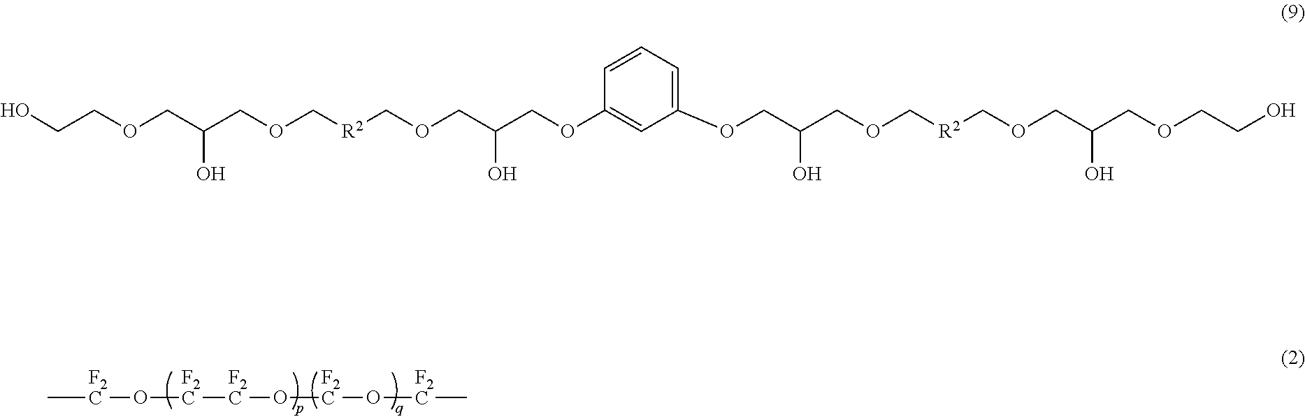
- a compound represented by the following formula (9) (4.4 g) was obtained in the same manner as in Example 1 except that fluoropolyether represented by HOCH 2 CF 2 O(CF 2 CF 2 O) p (CF 2 O) q CF 2 CH 2 OH (in the formula, p is 4.5 and q is 0) (number-average molecular weight: 650, molecular weight distribution: 1.2) was used in place of the fluoropolyether represented by HOCH 2 CF 2 O(CF 2 CF 2 O) p (CF 2 O) q CF 2 CH 2 OH (in the formula, p is 3.0 and q is 3.0) used in Example 1.
- fluoropolyether represented by HOCH 2 CF 2 O(CF 2 CF 2 O) p (CF 2 O) q CF 2 CH 2 OH in the formula, p is 3.0 and q is 3.0
- R 2 is represented by the following formula (2).
- R 2 is represented by the following formula (2).
- a compound represented by the following formula (13) (4.2 g) was obtained in the same manner as in Example 1 except that 1,4-butanediol was used in place of ethylene glycol used in Example 1.
- a compound represented by the following formula (16) (3.9 g) was obtained in the same manner as in Example 1 except that fluoropolyether represented by HOCH 2 CF 2 O(CF 2 CF 2 O) p (CF 2 O) q CF 2 CH 2 OH (in the formula, p is 4.5 and q is 0) (number-average molecular weight: 650, molecular weight distribution: 1.2) was used in place of the fluoropolyether represented by HOCH 2 CF 2 O(CF 2 CF 2 O) p (CF 2 O) q CF 2 CH 2 OH (in the formula, p is 3.0 and q is 3.0) used in Example 1, and the compound represented by the formula (14) was used in place of the compound represented by the formula (6).
- R 2 is represented by the following formula (2).
- R 2 is represented by the following formula (3).
- a compound represented by the following formula (18) (4.1 g) was obtained in the same manner as in Example 1 except that fluoropolyether represented by HOCH 2 CF 2 CF 2 CF 2 O(CF 2 CF 2 CF 2 O) s CF 2 CF 2 CF 2 CH 2 OH (in the formula, s is 1.5) (number-average molecular weight: 650, molecular weight distribution: 1.2) was used in place of the fluoropolyether represented by HOCH 2 CF 2 O(CF 2 CF 2 O) p (CF 2 O) q CF 2 CH 2 OH (in the formula, p is 3.0 and q is 3.0) used in Example 1, and the compound represented by the formula (14) was used in place of the compound represented by the formula (6).
- fluoropolyether represented by HOCH 2 CF 2 CF 2 CF 2 O(CF 2 CF 2 CF 2 O) s CF 2 CF 2 CF 2 CH 2 OH (number-average molecular
- R 2 is represented by the following formula (4).
- a compound represented by the following formula (19) was synthesized in the same manner as the compound represented by the formula (6) in Example 1 except that 1,3,5-trihydroxybenzene and epichlorohydrin were used.
- R 2 is represented by the following formula (2).
- a compound represented by the following formula (21) was synthesized in the same manner as the compound represented by the formula (14) in Example 7 except that 1,3,5-trihydroxybenzene and 1,3-dibromopropane were used.
- R 2 is represented by the following formula (2).
- a compound represented by the following formula (23) (4.8 g) was obtained in the same manner as in Example 1 except that fluoropolyether represented by HOCH 2 CF 2 O(CF 2 CF 2 O) p (CF 2 O) q CF 2 CH 2 OH (in the formula, p is 4.5 and q is 0) (number-average molecular weight: 650, molecular weight distribution: 1.2) was used in place of the fluoropolyether represented by HOCH 2 CF 2 O(CF 2 CF 2 O) p (CF 2 O) q CF 2 CH 2 OH (in the formula, p is 3.0 and q is 3.0) used in Example 1, and the compound represented by the formula (21) was used in place of the compound represented by the formula (6).
- R 2 is represented by the following formula (2).
- a compound represented by the following formula (24) (4.7 g) was obtained in the same manner as in Example 1 except that fluoropolyether represented by HOCH 2 CF 2 CF 2 O(CF 2 CF 2 CF 2 O) r CF 2 CF 2 CH 2 OH (in the formula, r is 2.5) (number-average molecular weight: 650, molecular weight distribution: 1.2) was used in place of the fluoropolyether represented by HOCH 2 CF 2 O(CF 2 CF 2 O) p (CF 2 O) q CF 2 CH 2 OH (in the formula, p is 3.0 and q is 3.0) used in Example 1, and the compound represented by the formula (21) was used in place of the compound represented by the formula (6).
- R 2 is represented by the following formula (3).
- a compound represented by the following formula (25) (4.2 g) was obtained in the same manner as in Example 1 except that fluoropolyether represented by HOCH 2 CF 2 CF 2 CF 2 O(CF 2 CF 2 CF 2 O) s CF 2 CF 2 CF 2 CH 2 OH (in the formula, s is 1.5) (number-average molecular weight: 650, molecular weight distribution: 1.2) was used in place of the fluoropolyether represented by HOCH 2 CF 2 O(CF 2 CF 2 O) p (CF 2 O) q CF 2 CH 2 OH (in the formula, p is 3.0 and q is 3.0) used in Example 1, and the compound represented by the formula (21) was used in place of the compound represented by the formula (6).
- fluoropolyether represented by HOCH 2 CF 2 CF 2 CF 2 O(CF 2 CF 2 CF 2 O) s CF 2 CF 2 CF 2 CH 2 OH (number-average molecular
- R 2 is represented by the following formula (4).
- a compound represented by the following formula (26) (4.6 g) was obtained in the same manner as in Example 1 except that the compound represented by the formula (21) was used in place of the compound represented by the formula (6) used in Example 1, and 1,3-propanediol was used in place of ethylene glycol.
- R 2 is represented by the following formula (2).
- a compound represented by the following formula (27) (4.6 g) was obtained in the same manner as in Example 1 except that the compound represented by the formula (21) was used in place of the compound represented by the formula (6) used in Example 1, and 1,4-butanediol was used in place of ethylene glycol.
- R 2 is represented by the following formula (2).
- a compound represented by the following formula (28) was synthesized by the method described in Patent Document 1.
- R 2 is represented by the following formula (4).
- a compound represented by the following formula (29) was synthesized by the method described in Patent Document 1.
- R 2 is represented by the following formula (4).
- a compound represented by the following formula (30) was synthesized by the method described in Patent Document 2.
- R 2 is represented by the following formula (4).
- a compound represented by the following formula (31) was synthesized by the method described in Patent Document 3.
- solutions for forming a lubricating layer were prepared using the compounds obtained in Examples 1 to 17 and Comparative Examples 1 to 4 by a method described below.
- lubricating layers for magnetic recording media were formed using the obtained solutions for forming a lubricating layer by a method described below, and magnetic recording media of Examples 1 to 17 and Comparative Examples 1 to 4 were obtained.
- Magnetic recording media each having an adhesive layer, a soft magnetic layer, a first underlayer, a second underlayer, a magnetic layer and a protective layer sequentially provided on a substrate having a diameter of 65 mm were prepared.
- a protective layer a carbon layer was used.
- the solutions for forming a lubricating layer of Examples 1 to 17 and Comparative Examples 1 to 4 were applied onto the protective layers of the magnetic recording media, in which the individual layers up to the protective layer had been formed, by the dipping method.
- the dipping method was carried out under conditions of an immersion speed of 10 mm/sec, an immersion time of 30 seconds and a lifting speed of 1.2 mm/sec.
- the magnetic recording media to which the solutions for forming a lubricating layer had been applied were put into a thermostatic chamber (120° C.) and heated for 10 minutes to remove the solvents in the solutions for forming a lubricating layer, thereby forming lubricating layers on the protective layers and obtaining magnetic recording media.
- the magnetic recording medium in which the lubricating layer was formed was washed by a method in which the magnetic recording medium was immersed in VERTREL XF, which was a solvent, for 10 minutes and lifted.
- the speed of immersing the magnetic recording medium into the solvent was set to 10 mm/sec, and the lifting speed was set to 1.2 mm/sec.
- the film thickness of the lubricating layer was measured by the same method as for the measurement of the film thickness of the lubricating layer before the washing.
- the film thickness of the lubricating layer before the washing was defined as A
- the film thickness of the lubricating layer after the washing was defined as B
- the bonding rate (bond rate) of the lubricant was calculated from the ratio between A and B ((B/A) ⁇ 100(%)).
- the adhesion between the lubricating layer and the protective layer was evaluated by references described below using the calculated bond rate.
- the bond rate is 50% or more and less than 65%.
- the magnetic recording medium and a magnetic head were mounted in a spin stand, and the magnetic head was floated at a fixed point for 10 minutes while rotating the magnetic recording medium at normal temperature under reduced pressure (approximately 250 torr). After that, the surface of the magnetic head that faced the magnetic recording medium (the surface of the lubricating layer) was analyzed using an analyzer for electron spectroscopy for chemical analysis (ESCA). In addition, the amount of the lubricant attached to the magnetic head was evaluated by references shown in Table 3 based on the intensity (signal intensity (a.u.)) of a fluorine-derived peak measured by ESCA.
- ESCA analyzer for electron spectroscopy for chemical analysis
- the sliding times until the friction coefficients of the surfaces of the lubricating layers sharply increased were measured.
- the sliding time until the friction coefficient sharply increased was measured four times for the lubricating layer of each magnetic recording medium, and the average value (time) was used as an index of the wear resistance of a lubricant coating.
- the time until the friction coefficient sharply increases can be used as an index of the wear resistance of the lubricating layers for the reason described below.
- the reason is that the use of the magnetic recording medium leads to wear of the lubricating layer in the magnetic recording medium, and, once the lubricating layer disappears due to the wear, the contact and the protective layer come into direct contact with each other, and the friction coefficient sharply increases.
- the time until the friction coefficient sharply increases is also considered to correlate with friction tests.
- the present invention is capable of providing a fluorine-containing ether compound that enables the formation of a lubricating layer in which wear resistance is excellent and pickup is suppressed in spite of a thin thickness, and can be preferably used as a material for lubricants for magnetic recording media.
- a lubricant for a magnetic recording medium containing the fluorine-containing ether compound of the present invention enables the formation of a lubricating layer in which wear resistance is excellent and pickup is suppressed in spite of a thin thickness.
Abstract
Description
- Japanese Patent No. 5816919
[Patent Document 2] - Japanese Patent No. 6198848
[Patent Document 3] - Japanese Patent No. 4632144
C6H6-n—[O—R1—O—CH2—R2—CH2—R3]n (1)


C6H6-n—[O—R1—O—CH2—R2—CH2—R3]n (1)


C6H6-n—[O—R—O—CH2—R2—CH2—OH]n (1-1)


| TABLE 1 | |||||
| Number of benzene | |||||
| Compound | substituents | R1 | R2 | R3 | |
| Example 1 | (5) | 2 | —CH2CH(OH)CH2— | Formula (2) | p = 3.0, q = 3.0 | m = 2 |
| Example 2 | (9) | 2 | —CH2CH(OH)CH2— | Formula (2) | p = 4.5, q = 0 | m = 2 |
| Example 3 | (10) | 2 | —CH2CH(OH)CH2— | Formula (3) | r = 2.5 | m = 2 |
| Example 4 | (11) | 2 | —CH2CH(OH)CH2— | Formula (4) | s = l .5 | m = 2 |
| Example 5 | (12) | 2 | —CH2CH(OH)CH2— | Formula (2) | p = 3.0, q = 3.0 | m = 3 |
| Example 6 | (13) | 2 | —CH2CH(OH)CH2— | Formula (2) | p = 3.0, q = 3.0 | m = 4 |
| Example 7 | (15) | 2 | —CH2CH2— | Formula (2) | p = 3.0, q = 3.0 | m = 2 |
| Example 8 | (16) | 2 | —CH2CH2— | Formula (2) | p = 4.5, q = 0 | m = 2 |
| Example 9 | (17) | 2 | —CH2CH2— | Formula (3) | r = 2.5 | m = 2 |
| Example 10 | (18) | 2 | —CH2CH2— | Formula (4) | s = 1.5 | m = 2 |
| Example 11 | (20) | 3 | —CH2CH(OH)CH2— | Formula (2) | p = 3.0, q = 3.0 | m = 2 |
| Example 12 | (22) | 3 | —CH2CH2CH2— | Formula (2) | p = 3.0, q = 3.0 | m = 2 |
| Example 13 | (23) | 3 | —CH2CH2CH2— | Formula (2) | p = 4.5, q = 0 | m = 2 |
| Example 14 | (24) | 3 | —CH2CH2CH2— | Formula (3) | r = 2.5 | m = 2 |
| Example 15 | (25) | 3 | —CH2CH2CH2— | Formula (4) | s = 1.5 | m = 2 |
| Example 16 | (26) | 3 | —CH2CH2CH2— | Formula (2) | p = 3.0, q = 3.0 | m = 3 |
| Example 17 | (27) | 3 | —CH2CH2CH2— | Formula (2) | p = 3.0, q = 3.0 | m = 4 |
| TABLE 2 | |||||||
| Number- | |||||||
| average | Film | Pickup | Wear | ||||
| molecular | thickness | Bond rate | suppression | resistance | Comprehensive | ||
| Compound | weight | (Å) | % | Evaluation | test | test | evaluation | |
| Example 1 | (5) | 1907 | 9.5 | 73% | A | AA | AA | AA |
| Example 2 | (9) | 1859 | 9.5 | 71% | A | AA | AA | AA |
| Example 3 | (10) | 1905 | 9.5 | 70% | A | AA | AA | AA |
| Example 4 | (11) | 1893 | 9.5 | 73% | A | AA | AA | AA |
| Example 5 | (12) | 1935 | 9.5 | 71% | A | AA | AA | AA |
| Example 6 | (13) | 1963 | 9.5 | 72% | A | AA | AA | AA |
| Example 7 | (15) | 1847 | 9.5 | 67% | A | AA | AA | AA |
| Example 8 | (16) | 1799 | 9.5 | 69% | A | AA | AA | AA |
| Example 9 | (17) | 1845 | 9.5 | 69% | A | AA | AA | AA |
| Example 10 | (18) | 1833 | 9.5 | 68% | A | AA | AA | AA |
| Example 11 | (20) | 2821 | 10.0 | 74% | A | AA | AA | AA |
| Example 12 | (22) | 2773 | 10.0 | 70% | A | AA | AA | AA |
| Example 13 | (23) | 2701 | 9.5 | 72% | A | AA | AA | AA |
| Example 14 | (24) | 2770 | 9.5 | 73% | A | AA | AA | AA |
| Example 15 | (25) | 2752 | 10.0 | 72% | A | AA | AA | AA |
| Example 16 | (26) | 2815 | 10.0 | 70% | A | AA | AA | AA |
| Example 17 | (27) | 2899 | 10.0 | 71% | A | AA | AA | AA |
| Comparative | (28) | 1805 | 9.5 | 62% | B | C | A | B |
| Example 1 | ||||||||
| Comparative | (29) | 1744 | 9.5 | 58% | B | C | B | B |
| Example 2 | ||||||||
| Comparative | (30) | 2620 | 10.0 | 35% | C | C | A | C |
| Example 3 | ||||||||
| Comparative | (31) | 2052 | 9.5 | 40% | C | C | A | C |
| Example 4 | ||||||||
| TABLE 3 | ||
| Eval- | ||
| uation | Signal intensity | ESCA signal intensity |
| AA | 500 or less | No lubricant is attached to the head, and |
| the signal intensity does not change. | ||
| A | More than 500 | The lubricant is slightly attached to the |
| and 1000 or less | head, and the signal intensity is small. | |
| C | More than 1000 | A large amount of the lubricant is attached |
| to the head, and the signal intensity is large. | ||
-
- AA (Excellent): 650 seconds or longer
- A (Favorable): 550 seconds or longer and shorter than 650 seconds
- B (Permissible): 450 seconds or longer and shorter than 550 seconds
- C (Impermissible): Shorter than 450 seconds
-
- 10 Magnetic recording medium
- 11 Substrate
- 12 Adhesive layer
- 13 Soft magnetic layer
- 14 First underlayer
- 15 Second underlayer
- 16 Magnetic layer
- 17 Protective layer
- 18 Lubricating layer
Claims (7)
C6H6-n—[O—R1—O—CH2—R2—CH2—R3]n (1)


Applications Claiming Priority (3)
| Application Number | Priority Date | Filing Date | Title |
|---|---|---|---|
| JP2019-181309 | 2019-10-01 | ||
| JP2019181309 | 2019-10-01 | ||
| PCT/JP2020/033949 WO2021065380A1 (en) | 2019-10-01 | 2020-09-08 | Fluorine-containing ether compound, lubricant for magnetic recording medium, and magnetic recording medium |
Publications (2)
| Publication Number | Publication Date |
|---|---|
| US20220380695A1 US20220380695A1 (en) | 2022-12-01 |
| US11845906B2 true US11845906B2 (en) | 2023-12-19 |
Family
ID=75337369
Family Applications (1)
| Application Number | Title | Priority Date | Filing Date |
|---|---|---|---|
| US17/765,175 Active 2040-10-17 US11845906B2 (en) | 2019-10-01 | 2020-09-08 | Fluorine-containing ether compound, lubricant for magnetic recording medium and magnetic recording medium |
Country Status (4)
| Country | Link |
|---|---|
| US (1) | US11845906B2 (en) |
| JP (1) | JPWO2021065380A1 (en) |
| CN (1) | CN114450263B (en) |
| WO (1) | WO2021065380A1 (en) |
Citations (13)
| Publication number | Priority date | Publication date | Assignee | Title |
|---|---|---|---|---|
| EP0165650B1 (en) * | 1984-06-19 | 1989-05-17 | AUSIMONT S.r.l. | Fluoropolyether compounds |
| JP4632144B2 (en) | 2007-09-14 | 2011-02-16 | 富士電機デバイステクノロジー株式会社 | Magnetic recording medium |
| US20120231297A1 (en) | 2011-03-07 | 2012-09-13 | Fujifilm Corporation | Lubricant composition, fluorine-based compound, and use thereof |
| US20120315504A1 (en) * | 2011-06-13 | 2012-12-13 | Tsuyoshi Shimizu | Fluoropolyether compound, lubricant and magnetic disk each containing the same |
| JP2013018961A (en) | 2011-06-13 | 2013-01-31 | Moresco Corp | Fluoropolyether compound, and lubricating agent and magnetic disc containing the same |
| US20130209837A1 (en) | 2012-02-13 | 2013-08-15 | Moresco Corporation | Fluoropolyether compound, lubricant and magnetic disk each containing the same |
| US20140368947A1 (en) * | 2013-06-14 | 2014-12-18 | HGST Netherlands B.V. | Magnetic recording medium lubricant mixture and systems thereof |
| WO2015093237A1 (en) | 2013-12-17 | 2015-06-25 | 株式会社Moresco | Fluoropolyether compound, lubricant containing same, and magnetic disk |
| US20150371672A1 (en) | 2013-12-09 | 2015-12-24 | Moresco Corporation | Fluoropolyether compound, and lubricant and magnetic disc comprising same |
| WO2016084781A1 (en) * | 2014-11-28 | 2016-06-02 | 株式会社Moresco | Fluoropolyether compound, lubricant, magnetic disk, and method for producing same |
| WO2017154403A1 (en) | 2016-03-10 | 2017-09-14 | 昭和電工株式会社 | Fluorine-containing ether compound, lubricating agent for magnetic recording media, and magnetic recording medium |
| WO2019039200A1 (en) | 2017-08-21 | 2019-02-28 | 昭和電工株式会社 | Fluorinated ether compound, lubricant for magnetic recording medium, and magnetic recording medium |
| CN109937224A (en) | 2016-12-20 | 2019-06-25 | 昭和电工株式会社 | Fluorine-containing ether compound, lubricant for magnetic recording medium and magnetic recording media |
-
2020
- 2020-09-08 CN CN202080068012.1A patent/CN114450263B/en active Active
- 2020-09-08 JP JP2021550517A patent/JPWO2021065380A1/ja active Pending
- 2020-09-08 US US17/765,175 patent/US11845906B2/en active Active
- 2020-09-08 WO PCT/JP2020/033949 patent/WO2021065380A1/en active Application Filing
Patent Citations (18)
| Publication number | Priority date | Publication date | Assignee | Title |
|---|---|---|---|---|
| EP0165650B1 (en) * | 1984-06-19 | 1989-05-17 | AUSIMONT S.r.l. | Fluoropolyether compounds |
| JP4632144B2 (en) | 2007-09-14 | 2011-02-16 | 富士電機デバイステクノロジー株式会社 | Magnetic recording medium |
| US20120231297A1 (en) | 2011-03-07 | 2012-09-13 | Fujifilm Corporation | Lubricant composition, fluorine-based compound, and use thereof |
| JP2012184339A (en) | 2011-03-07 | 2012-09-27 | Fujifilm Corp | Lubricant composition, fluorine compound, and use thereof |
| US20120315504A1 (en) * | 2011-06-13 | 2012-12-13 | Tsuyoshi Shimizu | Fluoropolyether compound, lubricant and magnetic disk each containing the same |
| JP2013018961A (en) | 2011-06-13 | 2013-01-31 | Moresco Corp | Fluoropolyether compound, and lubricating agent and magnetic disc containing the same |
| JP5816919B2 (en) | 2011-06-13 | 2015-11-18 | 株式会社Moresco | Fluoropolyether compound, lubricant containing the same, and magnetic disk |
| US20130209837A1 (en) | 2012-02-13 | 2013-08-15 | Moresco Corporation | Fluoropolyether compound, lubricant and magnetic disk each containing the same |
| US20140368947A1 (en) * | 2013-06-14 | 2014-12-18 | HGST Netherlands B.V. | Magnetic recording medium lubricant mixture and systems thereof |
| US20150371672A1 (en) | 2013-12-09 | 2015-12-24 | Moresco Corporation | Fluoropolyether compound, and lubricant and magnetic disc comprising same |
| WO2015093237A1 (en) | 2013-12-17 | 2015-06-25 | 株式会社Moresco | Fluoropolyether compound, lubricant containing same, and magnetic disk |
| US20160203839A1 (en) | 2013-12-17 | 2016-07-14 | Moresco Corporation | Fluoropolyether compound, lubricant containing same, and magnetic disk |
| JP6198848B2 (en) | 2013-12-17 | 2017-09-20 | 株式会社Moresco | Fluoropolyether compound, lubricant containing the same, and magnetic disk |
| WO2016084781A1 (en) * | 2014-11-28 | 2016-06-02 | 株式会社Moresco | Fluoropolyether compound, lubricant, magnetic disk, and method for producing same |
| WO2017154403A1 (en) | 2016-03-10 | 2017-09-14 | 昭和電工株式会社 | Fluorine-containing ether compound, lubricating agent for magnetic recording media, and magnetic recording medium |
| US20190084911A1 (en) | 2016-03-10 | 2019-03-21 | Showa Denko K.K. | Fluorine-containing ether compound, lubricant for magnetic recording medium, and magnetic recording medium |
| CN109937224A (en) | 2016-12-20 | 2019-06-25 | 昭和电工株式会社 | Fluorine-containing ether compound, lubricant for magnetic recording medium and magnetic recording media |
| WO2019039200A1 (en) | 2017-08-21 | 2019-02-28 | 昭和電工株式会社 | Fluorinated ether compound, lubricant for magnetic recording medium, and magnetic recording medium |
Non-Patent Citations (2)
| Title |
|---|
| International Search Report for PCT/JP2020/033949 dated Nov. 24, 2020. |
| Zhang Hui-chen et al., "Performances of Lubricants in Hard Disk and Their Influences on Dynamic Characteristics of Magnetic Recording System", Acta Tribology, 2004, vol. 24, No. 5, pp. 476-482 (7 pages). |
Also Published As
| Publication number | Publication date |
|---|---|
| WO2021065380A1 (en) | 2021-04-08 |
| CN114450263A (en) | 2022-05-06 |
| CN114450263B (en) | 2023-11-21 |
| JPWO2021065380A1 (en) | 2021-04-08 |
| US20220380695A1 (en) | 2022-12-01 |
Similar Documents
| Publication | Publication Date | Title |
|---|---|---|
| US20240034951A2 (en) | Fluorine-containing ether compound, lubricant for magnetic recording medium, and magnetic recording medium | |
| US11220649B2 (en) | Fluorine-containing ether compound, lubricant for magnetic recording medium, and magnetic recording medium | |
| US11225624B2 (en) | Fluorine-containing ether compound, lubricant for magnetic recording medium, and magnetic recording medium | |
| US11879109B2 (en) | Fluorine-containing ether compound, lubricant for magnetic recording medium, and magnetic recording medium | |
| US20230242829A1 (en) | Fluorine-containing ether compound, lubricant for magnetic recording medium, and magnetic recording medium | |
| US11905365B2 (en) | Fluorine-containing ether compound, lubricant for magnetic recording medium, and magnetic recording medium | |
| US20210155751A1 (en) | Fluorine-containing ether compound, lubricant for magnetic recording medium, and magnetic recording medium | |
| US11555005B2 (en) | Fluorine-containing ether compound, lubricant for magnetic recording medium, and magnetic recording medium | |
| US11912824B2 (en) | Fluorine-containing ether compound, lubricant for magnetic recording medium, and magnetic recording medium | |
| US11919875B2 (en) | Fluorine-containing ether compound, lubricant for magnetic recording medium, and magnetic recording medium | |
| US11845906B2 (en) | Fluorine-containing ether compound, lubricant for magnetic recording medium and magnetic recording medium | |
| US20230287288A1 (en) | Fluorine-containing ether compound, lubricant for magnetic recording medium, and magnetic recording medium | |
| US11767483B2 (en) | Fluorine-containing ether compound, lubricant for magnetic recording medium, and magnetic recording medium | |
| US20240002743A1 (en) | Fluorine-containing ether compound, lubricant for magnetic recording medium, and magnetic recording medium | |
| US11661408B2 (en) | Fluorine-containing ether compound, lubricant for magnetic recording medium, and magnetic recording medium | |
| WO2022215726A1 (en) | Fluorine-containing ether compound, lubricant for magnetic recording medium, and magnetic recording medium |
Legal Events
| Date | Code | Title | Description |
|---|---|---|---|
| AS | Assignment |
Owner name: SHOWA DENKO K.K., JAPAN Free format text: ASSIGNMENT OF ASSIGNORS INTEREST;ASSIGNORS:FUKUMOTO, NAOYA;YAGYU, DAISUKE;KATO, TSUYOSHI;AND OTHERS;SIGNING DATES FROM 20211217 TO 20220324;REEL/FRAME:059445/0196 |
|
| FEPP | Fee payment procedure |
Free format text: ENTITY STATUS SET TO UNDISCOUNTED (ORIGINAL EVENT CODE: BIG.); ENTITY STATUS OF PATENT OWNER: LARGE ENTITY |
|
| STPP | Information on status: patent application and granting procedure in general |
Free format text: DOCKETED NEW CASE - READY FOR EXAMINATION |
|
| AS | Assignment |
Owner name: RESONAC CORPORATION, JAPAN Free format text: CHANGE OF NAME;ASSIGNOR:SHOWA DENKO K.K.;REEL/FRAME:064082/0513 Effective date: 20230623 |
|
| STPP | Information on status: patent application and granting procedure in general |
Free format text: NOTICE OF ALLOWANCE MAILED -- APPLICATION RECEIVED IN OFFICE OF PUBLICATIONS |
|
| STPP | Information on status: patent application and granting procedure in general |
Free format text: PUBLICATIONS -- ISSUE FEE PAYMENT RECEIVED |
|
| STPP | Information on status: patent application and granting procedure in general |
Free format text: PUBLICATIONS -- ISSUE FEE PAYMENT VERIFIED |
|
| STCF | Information on status: patent grant |
Free format text: PATENTED CASE |
|
| AS | Assignment |
Owner name: RESONAC CORPORATION, JAPAN Free format text: CHANGE OF ADDRESS;ASSIGNOR:RESONAC CORPORATION;REEL/FRAME:066599/0037 Effective date: 20231001 |