WO2017122597A1 - 蓄電装置用水系電解液、及び当該水系電解液を含む蓄電装置 - Google Patents
蓄電装置用水系電解液、及び当該水系電解液を含む蓄電装置 Download PDFInfo
- Publication number
- WO2017122597A1 WO2017122597A1 PCT/JP2017/000320 JP2017000320W WO2017122597A1 WO 2017122597 A1 WO2017122597 A1 WO 2017122597A1 JP 2017000320 W JP2017000320 W JP 2017000320W WO 2017122597 A1 WO2017122597 A1 WO 2017122597A1
- Authority
- WO
- WIPO (PCT)
- Prior art keywords
- electrolytic solution
- storage device
- mol
- production example
- alkali metal
- Prior art date
Links
- 239000008151 electrolyte solution Substances 0.000 title claims abstract description 108
- 238000003860 storage Methods 0.000 title claims abstract description 63
- XLYOFNOQVPJJNP-UHFFFAOYSA-N water Substances O XLYOFNOQVPJJNP-UHFFFAOYSA-N 0.000 claims abstract description 74
- -1 alkali metal salt Chemical class 0.000 claims abstract description 62
- 229910052783 alkali metal Inorganic materials 0.000 claims abstract description 48
- 239000002904 solvent Substances 0.000 claims abstract description 19
- 239000003990 capacitor Substances 0.000 claims description 45
- 239000003792 electrolyte Substances 0.000 claims description 36
- OKTJSMMVPCPJKN-UHFFFAOYSA-N Carbon Chemical compound [C] OKTJSMMVPCPJKN-UHFFFAOYSA-N 0.000 claims description 31
- HBBGRARXTFLTSG-UHFFFAOYSA-N Lithium ion Chemical group [Li+] HBBGRARXTFLTSG-UHFFFAOYSA-N 0.000 claims description 26
- 229910001416 lithium ion Inorganic materials 0.000 claims description 22
- 229910052782 aluminium Inorganic materials 0.000 claims description 12
- XAGFODPZIPBFFR-UHFFFAOYSA-N aluminium Chemical compound [Al] XAGFODPZIPBFFR-UHFFFAOYSA-N 0.000 claims description 12
- 150000002891 organic anions Chemical group 0.000 claims description 11
- 229910001415 sodium ion Inorganic materials 0.000 claims description 10
- FKNQFGJONOIPTF-UHFFFAOYSA-N Sodium cation Chemical compound [Na+] FKNQFGJONOIPTF-UHFFFAOYSA-N 0.000 claims description 8
- 125000000217 alkyl group Chemical group 0.000 claims description 8
- 229910052799 carbon Inorganic materials 0.000 claims description 7
- 150000001450 anions Chemical class 0.000 claims description 3
- 229910003002 lithium salt Inorganic materials 0.000 claims description 3
- 159000000002 lithium salts Chemical group 0.000 claims description 3
- 159000000000 sodium salts Chemical class 0.000 claims description 3
- ZXMGHDIOOHOAAE-UHFFFAOYSA-N 1,1,1-trifluoro-n-(trifluoromethylsulfonyl)methanesulfonamide Chemical compound FC(F)(F)S(=O)(=O)NS(=O)(=O)C(F)(F)F ZXMGHDIOOHOAAE-UHFFFAOYSA-N 0.000 claims description 2
- DOYSIZKQWJYULQ-UHFFFAOYSA-N 1,1,2,2,2-pentafluoro-n-(1,1,2,2,2-pentafluoroethylsulfonyl)ethanesulfonamide Chemical compound FC(F)(F)C(F)(F)S(=O)(=O)NS(=O)(=O)C(F)(F)C(F)(F)F DOYSIZKQWJYULQ-UHFFFAOYSA-N 0.000 claims description 2
- JTKRNINHVGHDBS-UHFFFAOYSA-N 1,1,2,2,2-pentafluoro-n-(trifluoromethylsulfonyl)ethanesulfonamide Chemical compound FC(F)(F)C(F)(F)S(=O)(=O)NS(=O)(=O)C(F)(F)F JTKRNINHVGHDBS-UHFFFAOYSA-N 0.000 claims description 2
- 150000001721 carbon Chemical group 0.000 claims description 2
- 125000003709 fluoroalkyl group Chemical group 0.000 claims description 2
- 238000004519 manufacturing process Methods 0.000 description 95
- QSZMZKBZAYQGRS-UHFFFAOYSA-N lithium;bis(trifluoromethylsulfonyl)azanide Chemical compound [Li+].FC(F)(F)S(=O)(=O)[N-]S(=O)(=O)C(F)(F)F QSZMZKBZAYQGRS-UHFFFAOYSA-N 0.000 description 53
- 239000007864 aqueous solution Substances 0.000 description 51
- 238000011156 evaluation Methods 0.000 description 18
- 239000007773 negative electrode material Substances 0.000 description 16
- 229910052744 lithium Inorganic materials 0.000 description 15
- 229910052751 metal Inorganic materials 0.000 description 15
- 239000002184 metal Substances 0.000 description 15
- 239000000203 mixture Substances 0.000 description 15
- 238000002484 cyclic voltammetry Methods 0.000 description 14
- WHXSMMKQMYFTQS-UHFFFAOYSA-N Lithium Chemical compound [Li] WHXSMMKQMYFTQS-UHFFFAOYSA-N 0.000 description 11
- QVGXLLKOCUKJST-UHFFFAOYSA-N atomic oxygen Chemical compound [O] QVGXLLKOCUKJST-UHFFFAOYSA-N 0.000 description 11
- 239000001301 oxygen Substances 0.000 description 11
- 229910052760 oxygen Inorganic materials 0.000 description 11
- PXHVJJICTQNCMI-UHFFFAOYSA-N Nickel Chemical compound [Ni] PXHVJJICTQNCMI-UHFFFAOYSA-N 0.000 description 10
- 239000011230 binding agent Substances 0.000 description 9
- BASFCYQUMIYNBI-UHFFFAOYSA-N platinum Chemical compound [Pt] BASFCYQUMIYNBI-UHFFFAOYSA-N 0.000 description 9
- 150000002500 ions Chemical class 0.000 description 8
- 239000000463 material Substances 0.000 description 8
- 239000007774 positive electrode material Substances 0.000 description 7
- 239000004020 conductor Substances 0.000 description 6
- 239000003960 organic solvent Substances 0.000 description 6
- XEEYBQQBJWHFJM-UHFFFAOYSA-N Iron Chemical compound [Fe] XEEYBQQBJWHFJM-UHFFFAOYSA-N 0.000 description 5
- RTAQQCXQSZGOHL-UHFFFAOYSA-N Titanium Chemical compound [Ti] RTAQQCXQSZGOHL-UHFFFAOYSA-N 0.000 description 5
- 239000007772 electrode material Substances 0.000 description 5
- 229910002804 graphite Inorganic materials 0.000 description 5
- 239000010439 graphite Substances 0.000 description 5
- 229910052759 nickel Inorganic materials 0.000 description 5
- 229910052697 platinum Inorganic materials 0.000 description 5
- 239000010936 titanium Substances 0.000 description 5
- RYGMFSIKBFXOCR-UHFFFAOYSA-N Copper Chemical compound [Cu] RYGMFSIKBFXOCR-UHFFFAOYSA-N 0.000 description 4
- 239000002033 PVDF binder Substances 0.000 description 4
- 229910052802 copper Inorganic materials 0.000 description 4
- 239000010949 copper Substances 0.000 description 4
- 239000011888 foil Substances 0.000 description 4
- 229910044991 metal oxide Inorganic materials 0.000 description 4
- 150000004706 metal oxides Chemical class 0.000 description 4
- 229920002981 polyvinylidene fluoride Polymers 0.000 description 4
- 239000011734 sodium Substances 0.000 description 4
- 229910052723 transition metal Inorganic materials 0.000 description 4
- CSCPPACGZOOCGX-UHFFFAOYSA-N Acetone Chemical compound CC(C)=O CSCPPACGZOOCGX-UHFFFAOYSA-N 0.000 description 3
- WEVYAHXRMPXWCK-UHFFFAOYSA-N Acetonitrile Chemical compound CC#N WEVYAHXRMPXWCK-UHFFFAOYSA-N 0.000 description 3
- UFHFLCQGNIYNRP-UHFFFAOYSA-N Hydrogen Chemical compound [H][H] UFHFLCQGNIYNRP-UHFFFAOYSA-N 0.000 description 3
- OKKJLVBELUTLKV-UHFFFAOYSA-N Methanol Chemical compound OC OKKJLVBELUTLKV-UHFFFAOYSA-N 0.000 description 3
- 239000004698 Polyethylene Substances 0.000 description 3
- 239000004743 Polypropylene Substances 0.000 description 3
- 229910021607 Silver chloride Inorganic materials 0.000 description 3
- 239000006230 acetylene black Substances 0.000 description 3
- 229910045601 alloy Inorganic materials 0.000 description 3
- 239000000956 alloy Substances 0.000 description 3
- 239000003575 carbonaceous material Substances 0.000 description 3
- 230000000052 comparative effect Effects 0.000 description 3
- 150000001875 compounds Chemical class 0.000 description 3
- 238000000113 differential scanning calorimetry Methods 0.000 description 3
- 230000005611 electricity Effects 0.000 description 3
- 239000007789 gas Substances 0.000 description 3
- 229910052736 halogen Inorganic materials 0.000 description 3
- 150000002367 halogens Chemical class 0.000 description 3
- 239000001257 hydrogen Substances 0.000 description 3
- 229910052739 hydrogen Inorganic materials 0.000 description 3
- 239000003112 inhibitor Substances 0.000 description 3
- 238000000034 method Methods 0.000 description 3
- 150000004767 nitrides Chemical class 0.000 description 3
- 239000004745 nonwoven fabric Substances 0.000 description 3
- 229920000573 polyethylene Polymers 0.000 description 3
- 229920001155 polypropylene Polymers 0.000 description 3
- 150000003839 salts Chemical class 0.000 description 3
- 229910052708 sodium Inorganic materials 0.000 description 3
- 239000010935 stainless steel Substances 0.000 description 3
- 229910001220 stainless steel Inorganic materials 0.000 description 3
- 150000003624 transition metals Chemical class 0.000 description 3
- 239000011701 zinc Substances 0.000 description 3
- OIFBSDVPJOWBCH-UHFFFAOYSA-N Diethyl carbonate Chemical compound CCOC(=O)OCC OIFBSDVPJOWBCH-UHFFFAOYSA-N 0.000 description 2
- IAZDPXIOMUYVGZ-UHFFFAOYSA-N Dimethylsulphoxide Chemical compound CS(C)=O IAZDPXIOMUYVGZ-UHFFFAOYSA-N 0.000 description 2
- KMTRUDSVKNLOMY-UHFFFAOYSA-N Ethylene carbonate Chemical compound O=C1OCCO1 KMTRUDSVKNLOMY-UHFFFAOYSA-N 0.000 description 2
- YCKRFDGAMUMZLT-UHFFFAOYSA-N Fluorine atom Chemical compound [F] YCKRFDGAMUMZLT-UHFFFAOYSA-N 0.000 description 2
- AEMRFAOFKBGASW-UHFFFAOYSA-N Glycolic acid Chemical compound OCC(O)=O AEMRFAOFKBGASW-UHFFFAOYSA-N 0.000 description 2
- 229910018091 Li 2 S Inorganic materials 0.000 description 2
- 229910015643 LiMn 2 O 4 Inorganic materials 0.000 description 2
- 229910013553 LiNO Inorganic materials 0.000 description 2
- HCHKCACWOHOZIP-UHFFFAOYSA-N Zinc Chemical compound [Zn] HCHKCACWOHOZIP-UHFFFAOYSA-N 0.000 description 2
- 239000003125 aqueous solvent Substances 0.000 description 2
- 239000003054 catalyst Substances 0.000 description 2
- 150000001768 cations Chemical class 0.000 description 2
- 230000003750 conditioning effect Effects 0.000 description 2
- 238000000354 decomposition reaction Methods 0.000 description 2
- 238000003795 desorption Methods 0.000 description 2
- QHGJSLXSVXVKHZ-UHFFFAOYSA-N dilithium;dioxido(dioxo)manganese Chemical compound [Li+].[Li+].[O-][Mn]([O-])(=O)=O QHGJSLXSVXVKHZ-UHFFFAOYSA-N 0.000 description 2
- KZTYYGOKRVBIMI-UHFFFAOYSA-N diphenyl sulfone Chemical compound C=1C=CC=CC=1S(=O)(=O)C1=CC=CC=C1 KZTYYGOKRVBIMI-UHFFFAOYSA-N 0.000 description 2
- 238000007599 discharging Methods 0.000 description 2
- 238000005516 engineering process Methods 0.000 description 2
- 229920000840 ethylene tetrafluoroethylene copolymer Polymers 0.000 description 2
- 229910052731 fluorine Inorganic materials 0.000 description 2
- 239000011737 fluorine Substances 0.000 description 2
- 229910052742 iron Inorganic materials 0.000 description 2
- KWGKDLIKAYFUFQ-UHFFFAOYSA-M lithium chloride Chemical compound [Li+].[Cl-] KWGKDLIKAYFUFQ-UHFFFAOYSA-M 0.000 description 2
- GELKBWJHTRAYNV-UHFFFAOYSA-K lithium iron phosphate Chemical compound [Li+].[Fe+2].[O-]P([O-])([O-])=O GELKBWJHTRAYNV-UHFFFAOYSA-K 0.000 description 2
- 230000014759 maintenance of location Effects 0.000 description 2
- 238000005259 measurement Methods 0.000 description 2
- 238000002844 melting Methods 0.000 description 2
- 230000008018 melting Effects 0.000 description 2
- 150000002736 metal compounds Chemical class 0.000 description 2
- 229910052976 metal sulfide Inorganic materials 0.000 description 2
- VNWKTOKETHGBQD-UHFFFAOYSA-N methane Chemical compound C VNWKTOKETHGBQD-UHFFFAOYSA-N 0.000 description 2
- 239000012046 mixed solvent Substances 0.000 description 2
- 229910021382 natural graphite Inorganic materials 0.000 description 2
- 230000003647 oxidation Effects 0.000 description 2
- 238000007254 oxidation reaction Methods 0.000 description 2
- 229920001343 polytetrafluoroethylene Polymers 0.000 description 2
- 239000004810 polytetrafluoroethylene Substances 0.000 description 2
- 239000000843 powder Substances 0.000 description 2
- 238000006479 redox reaction Methods 0.000 description 2
- 229920005989 resin Polymers 0.000 description 2
- 239000011347 resin Substances 0.000 description 2
- 238000001179 sorption measurement Methods 0.000 description 2
- HHVIBTZHLRERCL-UHFFFAOYSA-N sulfonyldimethane Chemical compound CS(C)(=O)=O HHVIBTZHLRERCL-UHFFFAOYSA-N 0.000 description 2
- 150000003464 sulfur compounds Chemical class 0.000 description 2
- 239000003115 supporting electrolyte Substances 0.000 description 2
- 229910052719 titanium Inorganic materials 0.000 description 2
- 229910000314 transition metal oxide Inorganic materials 0.000 description 2
- 229910052725 zinc Inorganic materials 0.000 description 2
- WDXYVJKNSMILOQ-UHFFFAOYSA-N 1,3,2-dioxathiolane 2-oxide Chemical compound O=S1OCCO1 WDXYVJKNSMILOQ-UHFFFAOYSA-N 0.000 description 1
- FSSPGSAQUIYDCN-UHFFFAOYSA-N 1,3-Propane sultone Chemical compound O=S1(=O)CCCO1 FSSPGSAQUIYDCN-UHFFFAOYSA-N 0.000 description 1
- VUZNLSBZRVZGIK-UHFFFAOYSA-N 2,2,6,6-Tetramethyl-1-piperidinol Chemical group CC1(C)CCCC(C)(C)N1O VUZNLSBZRVZGIK-UHFFFAOYSA-N 0.000 description 1
- FALRKNHUBBKYCC-UHFFFAOYSA-N 2-(chloromethyl)pyridine-3-carbonitrile Chemical compound ClCC1=NC=CC=C1C#N FALRKNHUBBKYCC-UHFFFAOYSA-N 0.000 description 1
- HHCHLHOEAKKCAB-UHFFFAOYSA-N 2-oxaspiro[3.5]nonane-1,3-dione Chemical compound O=C1OC(=O)C11CCCCC1 HHCHLHOEAKKCAB-UHFFFAOYSA-N 0.000 description 1
- SYIUWAVTBADRJG-UHFFFAOYSA-N 2H-pyran-2,6(3H)-dione Chemical compound O=C1CC=CC(=O)O1 SYIUWAVTBADRJG-UHFFFAOYSA-N 0.000 description 1
- BUZICZZQJDLXJN-UHFFFAOYSA-N 3-azaniumyl-4-hydroxybutanoate Chemical compound OCC(N)CC(O)=O BUZICZZQJDLXJN-UHFFFAOYSA-N 0.000 description 1
- AYKYXWQEBUNJCN-UHFFFAOYSA-N 3-methylfuran-2,5-dione Chemical compound CC1=CC(=O)OC1=O AYKYXWQEBUNJCN-UHFFFAOYSA-N 0.000 description 1
- OFNISBHGPNMTMS-UHFFFAOYSA-N 3-methylideneoxolane-2,5-dione Chemical compound C=C1CC(=O)OC1=O OFNISBHGPNMTMS-UHFFFAOYSA-N 0.000 description 1
- HDFKMLFDDYWABF-UHFFFAOYSA-N 3-phenyloxolane-2,5-dione Chemical compound O=C1OC(=O)CC1C1=CC=CC=C1 HDFKMLFDDYWABF-UHFFFAOYSA-N 0.000 description 1
- 229920003026 Acene Polymers 0.000 description 1
- 229910000838 Al alloy Inorganic materials 0.000 description 1
- COVZYZSDYWQREU-UHFFFAOYSA-N Busulfan Chemical compound CS(=O)(=O)OCCCCOS(C)(=O)=O COVZYZSDYWQREU-UHFFFAOYSA-N 0.000 description 1
- 229920000049 Carbon (fiber) Polymers 0.000 description 1
- BVKZGUZCCUSVTD-UHFFFAOYSA-L Carbonate Chemical compound [O-]C([O-])=O BVKZGUZCCUSVTD-UHFFFAOYSA-L 0.000 description 1
- CUDSBWGCGSUXDB-UHFFFAOYSA-N Dibutyl disulfide Chemical compound CCCCSSCCCC CUDSBWGCGSUXDB-UHFFFAOYSA-N 0.000 description 1
- ODHAQPXNQDBHSH-UHFFFAOYSA-N Dicyclohexyl disulfide Chemical compound C1CCCCC1SSC1CCCCC1 ODHAQPXNQDBHSH-UHFFFAOYSA-N 0.000 description 1
- MYMOFIZGZYHOMD-UHFFFAOYSA-N Dioxygen Chemical compound O=O MYMOFIZGZYHOMD-UHFFFAOYSA-N 0.000 description 1
- DGAQECJNVWCQMB-PUAWFVPOSA-M Ilexoside XXIX Chemical compound C[C@@H]1CC[C@@]2(CC[C@@]3(C(=CC[C@H]4[C@]3(CC[C@@H]5[C@@]4(CC[C@@H](C5(C)C)OS(=O)(=O)[O-])C)C)[C@@H]2[C@]1(C)O)C)C(=O)O[C@H]6[C@@H]([C@H]([C@@H]([C@H](O6)CO)O)O)O.[Na+] DGAQECJNVWCQMB-PUAWFVPOSA-M 0.000 description 1
- 229910013063 LiBF 4 Inorganic materials 0.000 description 1
- 229910013684 LiClO 4 Inorganic materials 0.000 description 1
- 229910012851 LiCoO 2 Inorganic materials 0.000 description 1
- 229910010707 LiFePO 4 Inorganic materials 0.000 description 1
- 229910013716 LiNi Inorganic materials 0.000 description 1
- 229910013290 LiNiO 2 Inorganic materials 0.000 description 1
- 229910013870 LiPF 6 Inorganic materials 0.000 description 1
- FYYHWMGAXLPEAU-UHFFFAOYSA-N Magnesium Chemical compound [Mg] FYYHWMGAXLPEAU-UHFFFAOYSA-N 0.000 description 1
- 229910000978 Pb alloy Inorganic materials 0.000 description 1
- 239000004952 Polyamide Substances 0.000 description 1
- 229920000265 Polyparaphenylene Polymers 0.000 description 1
- 229910000676 Si alloy Inorganic materials 0.000 description 1
- BQCADISMDOOEFD-UHFFFAOYSA-N Silver Chemical compound [Ag] BQCADISMDOOEFD-UHFFFAOYSA-N 0.000 description 1
- 229910001128 Sn alloy Inorganic materials 0.000 description 1
- KEAYESYHFKHZAL-UHFFFAOYSA-N Sodium Chemical compound [Na] KEAYESYHFKHZAL-UHFFFAOYSA-N 0.000 description 1
- NINIDFKCEFEMDL-UHFFFAOYSA-N Sulfur Chemical compound [S] NINIDFKCEFEMDL-UHFFFAOYSA-N 0.000 description 1
- JFBZPFYRPYOZCQ-UHFFFAOYSA-N [Li].[Al] Chemical compound [Li].[Al] JFBZPFYRPYOZCQ-UHFFFAOYSA-N 0.000 description 1
- QSNQXZYQEIKDPU-UHFFFAOYSA-N [Li].[Fe] Chemical compound [Li].[Fe] QSNQXZYQEIKDPU-UHFFFAOYSA-N 0.000 description 1
- KLARSDUHONHPRF-UHFFFAOYSA-N [Li].[Mn] Chemical compound [Li].[Mn] KLARSDUHONHPRF-UHFFFAOYSA-N 0.000 description 1
- ZVLDJSZFKQJMKD-UHFFFAOYSA-N [Li].[Si] Chemical compound [Li].[Si] ZVLDJSZFKQJMKD-UHFFFAOYSA-N 0.000 description 1
- PWBXDCPGSHVVPB-UHFFFAOYSA-K [O-]P([O-])(=O)OP(=O)([O-])O.[Fe+2].[Li+] Chemical compound [O-]P([O-])(=O)OP(=O)([O-])O.[Fe+2].[Li+] PWBXDCPGSHVVPB-UHFFFAOYSA-K 0.000 description 1
- GTDPSWPPOUPBNX-UHFFFAOYSA-N ac1mqpva Chemical compound CC12C(=O)OC(=O)C1(C)C1(C)C2(C)C(=O)OC1=O GTDPSWPPOUPBNX-UHFFFAOYSA-N 0.000 description 1
- 150000001298 alcohols Chemical class 0.000 description 1
- 125000003368 amide group Chemical group 0.000 description 1
- 150000008064 anhydrides Chemical class 0.000 description 1
- 229910021383 artificial graphite Inorganic materials 0.000 description 1
- 125000003118 aryl group Chemical group 0.000 description 1
- 230000004888 barrier function Effects 0.000 description 1
- 229960002092 busulfan Drugs 0.000 description 1
- 239000006229 carbon black Substances 0.000 description 1
- 239000004917 carbon fiber Substances 0.000 description 1
- 229910021393 carbon nanotube Inorganic materials 0.000 description 1
- 239000002041 carbon nanotube Substances 0.000 description 1
- 150000004649 carbonic acid derivatives Chemical class 0.000 description 1
- 150000001244 carboxylic acid anhydrides Chemical class 0.000 description 1
- 125000002091 cationic group Chemical group 0.000 description 1
- 229920002678 cellulose Polymers 0.000 description 1
- 239000001913 cellulose Substances 0.000 description 1
- 239000002800 charge carrier Substances 0.000 description 1
- 238000006243 chemical reaction Methods 0.000 description 1
- 239000003795 chemical substances by application Substances 0.000 description 1
- 229910017052 cobalt Inorganic materials 0.000 description 1
- 239000010941 cobalt Substances 0.000 description 1
- GUTLYIVDDKVIGB-UHFFFAOYSA-N cobalt atom Chemical compound [Co] GUTLYIVDDKVIGB-UHFFFAOYSA-N 0.000 description 1
- 229920001940 conductive polymer Polymers 0.000 description 1
- 238000005260 corrosion Methods 0.000 description 1
- 230000007797 corrosion Effects 0.000 description 1
- STZIXLPVKZUAMV-UHFFFAOYSA-N cyclopentane-1,1,2,2-tetracarboxylic acid Chemical compound OC(=O)C1(C(O)=O)CCCC1(C(O)=O)C(O)=O STZIXLPVKZUAMV-UHFFFAOYSA-N 0.000 description 1
- 238000001938 differential scanning calorimetry curve Methods 0.000 description 1
- 238000009792 diffusion process Methods 0.000 description 1
- IEJIGPNLZYLLBP-UHFFFAOYSA-N dimethyl carbonate Chemical compound COC(=O)OC IEJIGPNLZYLLBP-UHFFFAOYSA-N 0.000 description 1
- 238000007606 doctor blade method Methods 0.000 description 1
- QHSJIZLJUFMIFP-UHFFFAOYSA-N ethene;1,1,2,2-tetrafluoroethene Chemical group C=C.FC(F)=C(F)F QHSJIZLJUFMIFP-UHFFFAOYSA-N 0.000 description 1
- JBTWLSYIZRCDFO-UHFFFAOYSA-N ethyl methyl carbonate Chemical compound CCOC(=O)OC JBTWLSYIZRCDFO-UHFFFAOYSA-N 0.000 description 1
- 238000004880 explosion Methods 0.000 description 1
- 239000000835 fiber Substances 0.000 description 1
- 238000010304 firing Methods 0.000 description 1
- 239000003365 glass fiber Substances 0.000 description 1
- VANNPISTIUFMLH-UHFFFAOYSA-N glutaric anhydride Chemical compound O=C1CCCC(=O)O1 VANNPISTIUFMLH-UHFFFAOYSA-N 0.000 description 1
- 229910021385 hard carbon Inorganic materials 0.000 description 1
- 230000006872 improvement Effects 0.000 description 1
- 239000011810 insulating material Substances 0.000 description 1
- 229910001337 iron nitride Inorganic materials 0.000 description 1
- 239000003273 ketjen black Substances 0.000 description 1
- JWZCKIBZGMIRSW-UHFFFAOYSA-N lead lithium Chemical compound [Li].[Pb] JWZCKIBZGMIRSW-UHFFFAOYSA-N 0.000 description 1
- FUJCRWPEOMXPAD-UHFFFAOYSA-N lithium oxide Chemical compound [Li+].[Li+].[O-2] FUJCRWPEOMXPAD-UHFFFAOYSA-N 0.000 description 1
- 229910001947 lithium oxide Inorganic materials 0.000 description 1
- UIDWHMKSOZZDAV-UHFFFAOYSA-N lithium tin Chemical compound [Li].[Sn] UIDWHMKSOZZDAV-UHFFFAOYSA-N 0.000 description 1
- ACFSQHQYDZIPRL-UHFFFAOYSA-N lithium;bis(1,1,2,2,2-pentafluoroethylsulfonyl)azanide Chemical compound [Li+].FC(F)(F)C(F)(F)S(=O)(=O)[N-]S(=O)(=O)C(F)(F)C(F)(F)F ACFSQHQYDZIPRL-UHFFFAOYSA-N 0.000 description 1
- 239000011777 magnesium Substances 0.000 description 1
- 229910052749 magnesium Inorganic materials 0.000 description 1
- FPYJFEHAWHCUMM-UHFFFAOYSA-N maleic anhydride Chemical compound O=C1OC(=O)C=C1 FPYJFEHAWHCUMM-UHFFFAOYSA-N 0.000 description 1
- 239000011572 manganese Substances 0.000 description 1
- WPBNNNQJVZRUHP-UHFFFAOYSA-L manganese(2+);methyl n-[[2-(methoxycarbonylcarbamothioylamino)phenyl]carbamothioyl]carbamate;n-[2-(sulfidocarbothioylamino)ethyl]carbamodithioate Chemical compound [Mn+2].[S-]C(=S)NCCNC([S-])=S.COC(=O)NC(=S)NC1=CC=CC=C1NC(=S)NC(=O)OC WPBNNNQJVZRUHP-UHFFFAOYSA-L 0.000 description 1
- MBABOKRGFJTBAE-UHFFFAOYSA-N methyl methanesulfonate Chemical group COS(C)(=O)=O MBABOKRGFJTBAE-UHFFFAOYSA-N 0.000 description 1
- GDOPTJXRTPNYNR-UHFFFAOYSA-N methyl-cyclopentane Natural products CC1CCCC1 GDOPTJXRTPNYNR-UHFFFAOYSA-N 0.000 description 1
- JCDWETOKTFWTHA-UHFFFAOYSA-N methylsulfonylbenzene Chemical compound CS(=O)(=O)C1=CC=CC=C1 JCDWETOKTFWTHA-UHFFFAOYSA-N 0.000 description 1
- 238000002156 mixing Methods 0.000 description 1
- 238000012986 modification Methods 0.000 description 1
- 230000004048 modification Effects 0.000 description 1
- 238000000465 moulding Methods 0.000 description 1
- WCFDSGHAIGTEKL-UHFFFAOYSA-N n,n-dimethylmethanesulfonamide Chemical compound CN(C)S(C)(=O)=O WCFDSGHAIGTEKL-UHFFFAOYSA-N 0.000 description 1
- 229910052757 nitrogen Inorganic materials 0.000 description 1
- 239000012299 nitrogen atmosphere Substances 0.000 description 1
- 239000010450 olivine Substances 0.000 description 1
- 229910052609 olivine Inorganic materials 0.000 description 1
- MHYFEEDKONKGEB-UHFFFAOYSA-N oxathiane 2,2-dioxide Chemical compound O=S1(=O)CCCCO1 MHYFEEDKONKGEB-UHFFFAOYSA-N 0.000 description 1
- 239000011301 petroleum pitch Substances 0.000 description 1
- 239000002798 polar solvent Substances 0.000 description 1
- 229920002647 polyamide Polymers 0.000 description 1
- 229920000447 polyanionic polymer Polymers 0.000 description 1
- 229920000728 polyester Polymers 0.000 description 1
- 239000011148 porous material Substances 0.000 description 1
- 238000002360 preparation method Methods 0.000 description 1
- 230000001737 promoting effect Effects 0.000 description 1
- QQONPFPTGQHPMA-UHFFFAOYSA-N propylene Natural products CC=C QQONPFPTGQHPMA-UHFFFAOYSA-N 0.000 description 1
- 125000004805 propylene group Chemical group [H]C([H])([H])C([H])([*:1])C([H])([H])[*:2] 0.000 description 1
- 150000003242 quaternary ammonium salts Chemical class 0.000 description 1
- 239000002994 raw material Substances 0.000 description 1
- 230000009467 reduction Effects 0.000 description 1
- 238000006722 reduction reaction Methods 0.000 description 1
- 238000011160 research Methods 0.000 description 1
- 229910052709 silver Inorganic materials 0.000 description 1
- 239000004332 silver Substances 0.000 description 1
- ZBBPIPBQOVVXIW-UHFFFAOYSA-N sodium;1,1,2,2,2-pentafluoroethylsulfonyl(trifluoromethylsulfonyl)azanide Chemical compound [Na+].FC(F)(F)C(F)(F)S(=O)(=O)[N-]S(=O)(=O)C(F)(F)F ZBBPIPBQOVVXIW-UHFFFAOYSA-N 0.000 description 1
- QSTITLHDMBEKHE-UHFFFAOYSA-N sodium;bis(1,1,2,2,2-pentafluoroethylsulfonyl)azanide Chemical compound [Na+].FC(F)(F)C(F)(F)S(=O)(=O)[N-]S(=O)(=O)C(F)(F)C(F)(F)F QSTITLHDMBEKHE-UHFFFAOYSA-N 0.000 description 1
- 229910021384 soft carbon Inorganic materials 0.000 description 1
- 238000007711 solidification Methods 0.000 description 1
- 230000008023 solidification Effects 0.000 description 1
- 239000000243 solution Substances 0.000 description 1
- 229910052596 spinel Inorganic materials 0.000 description 1
- 239000011029 spinel Substances 0.000 description 1
- 125000000547 substituted alkyl group Chemical group 0.000 description 1
- 238000006467 substitution reaction Methods 0.000 description 1
- 229940014800 succinic anhydride Drugs 0.000 description 1
- HXJUTPCZVOIRIF-UHFFFAOYSA-N sulfolane Chemical compound O=S1(=O)CCCC1 HXJUTPCZVOIRIF-UHFFFAOYSA-N 0.000 description 1
- MBDNRNMVTZADMQ-UHFFFAOYSA-N sulfolene Chemical compound O=S1(=O)CC=CC1 MBDNRNMVTZADMQ-UHFFFAOYSA-N 0.000 description 1
- 229910052717 sulfur Inorganic materials 0.000 description 1
- 239000011593 sulfur Substances 0.000 description 1
- 229920003002 synthetic resin Polymers 0.000 description 1
- 239000000057 synthetic resin Substances 0.000 description 1
Images


Classifications
-
- H—ELECTRICITY
- H01—ELECTRIC ELEMENTS
- H01M—PROCESSES OR MEANS, e.g. BATTERIES, FOR THE DIRECT CONVERSION OF CHEMICAL ENERGY INTO ELECTRICAL ENERGY
- H01M10/00—Secondary cells; Manufacture thereof
- H01M10/36—Accumulators not provided for in groups H01M10/05-H01M10/34
-
- H—ELECTRICITY
- H01—ELECTRIC ELEMENTS
- H01G—CAPACITORS; CAPACITORS, RECTIFIERS, DETECTORS, SWITCHING DEVICES, LIGHT-SENSITIVE OR TEMPERATURE-SENSITIVE DEVICES OF THE ELECTROLYTIC TYPE
- H01G11/00—Hybrid capacitors, i.e. capacitors having different positive and negative electrodes; Electric double-layer [EDL] capacitors; Processes for the manufacture thereof or of parts thereof
- H01G11/54—Electrolytes
- H01G11/58—Liquid electrolytes
- H01G11/60—Liquid electrolytes characterised by the solvent
-
- H—ELECTRICITY
- H01—ELECTRIC ELEMENTS
- H01G—CAPACITORS; CAPACITORS, RECTIFIERS, DETECTORS, SWITCHING DEVICES, LIGHT-SENSITIVE OR TEMPERATURE-SENSITIVE DEVICES OF THE ELECTROLYTIC TYPE
- H01G11/00—Hybrid capacitors, i.e. capacitors having different positive and negative electrodes; Electric double-layer [EDL] capacitors; Processes for the manufacture thereof or of parts thereof
- H01G11/54—Electrolytes
- H01G11/58—Liquid electrolytes
- H01G11/62—Liquid electrolytes characterised by the solute, e.g. salts, anions or cations therein
-
- H—ELECTRICITY
- H01—ELECTRIC ELEMENTS
- H01G—CAPACITORS; CAPACITORS, RECTIFIERS, DETECTORS, SWITCHING DEVICES, LIGHT-SENSITIVE OR TEMPERATURE-SENSITIVE DEVICES OF THE ELECTROLYTIC TYPE
- H01G11/00—Hybrid capacitors, i.e. capacitors having different positive and negative electrodes; Electric double-layer [EDL] capacitors; Processes for the manufacture thereof or of parts thereof
- H01G11/54—Electrolytes
- H01G11/58—Liquid electrolytes
- H01G11/64—Liquid electrolytes characterised by additives
-
- H—ELECTRICITY
- H01—ELECTRIC ELEMENTS
- H01M—PROCESSES OR MEANS, e.g. BATTERIES, FOR THE DIRECT CONVERSION OF CHEMICAL ENERGY INTO ELECTRICAL ENERGY
- H01M4/00—Electrodes
- H01M4/02—Electrodes composed of, or comprising, active material
- H01M4/36—Selection of substances as active materials, active masses, active liquids
- H01M4/58—Selection of substances as active materials, active masses, active liquids of inorganic compounds other than oxides or hydroxides, e.g. sulfides, selenides, tellurides, halogenides or LiCoFy; of polyanionic structures, e.g. phosphates, silicates or borates
- H01M4/583—Carbonaceous material, e.g. graphite-intercalation compounds or CFx
- H01M4/587—Carbonaceous material, e.g. graphite-intercalation compounds or CFx for inserting or intercalating light metals
-
- H—ELECTRICITY
- H01—ELECTRIC ELEMENTS
- H01M—PROCESSES OR MEANS, e.g. BATTERIES, FOR THE DIRECT CONVERSION OF CHEMICAL ENERGY INTO ELECTRICAL ENERGY
- H01M4/00—Electrodes
- H01M4/02—Electrodes composed of, or comprising, active material
- H01M4/64—Carriers or collectors
- H01M4/66—Selection of materials
- H01M4/661—Metal or alloys, e.g. alloy coatings
-
- H—ELECTRICITY
- H01—ELECTRIC ELEMENTS
- H01G—CAPACITORS; CAPACITORS, RECTIFIERS, DETECTORS, SWITCHING DEVICES, LIGHT-SENSITIVE OR TEMPERATURE-SENSITIVE DEVICES OF THE ELECTROLYTIC TYPE
- H01G11/00—Hybrid capacitors, i.e. capacitors having different positive and negative electrodes; Electric double-layer [EDL] capacitors; Processes for the manufacture thereof or of parts thereof
- H01G11/22—Electrodes
- H01G11/30—Electrodes characterised by their material
- H01G11/32—Carbon-based
- H01G11/34—Carbon-based characterised by carbonisation or activation of carbon
-
- H—ELECTRICITY
- H01—ELECTRIC ELEMENTS
- H01G—CAPACITORS; CAPACITORS, RECTIFIERS, DETECTORS, SWITCHING DEVICES, LIGHT-SENSITIVE OR TEMPERATURE-SENSITIVE DEVICES OF THE ELECTROLYTIC TYPE
- H01G11/00—Hybrid capacitors, i.e. capacitors having different positive and negative electrodes; Electric double-layer [EDL] capacitors; Processes for the manufacture thereof or of parts thereof
- H01G11/66—Current collectors
- H01G11/68—Current collectors characterised by their material
-
- H—ELECTRICITY
- H01—ELECTRIC ELEMENTS
- H01M—PROCESSES OR MEANS, e.g. BATTERIES, FOR THE DIRECT CONVERSION OF CHEMICAL ENERGY INTO ELECTRICAL ENERGY
- H01M2300/00—Electrolytes
- H01M2300/0002—Aqueous electrolytes
-
- Y—GENERAL TAGGING OF NEW TECHNOLOGICAL DEVELOPMENTS; GENERAL TAGGING OF CROSS-SECTIONAL TECHNOLOGIES SPANNING OVER SEVERAL SECTIONS OF THE IPC; TECHNICAL SUBJECTS COVERED BY FORMER USPC CROSS-REFERENCE ART COLLECTIONS [XRACs] AND DIGESTS
- Y02—TECHNOLOGIES OR APPLICATIONS FOR MITIGATION OR ADAPTATION AGAINST CLIMATE CHANGE
- Y02E—REDUCTION OF GREENHOUSE GAS [GHG] EMISSIONS, RELATED TO ENERGY GENERATION, TRANSMISSION OR DISTRIBUTION
- Y02E60/00—Enabling technologies; Technologies with a potential or indirect contribution to GHG emissions mitigation
- Y02E60/10—Energy storage using batteries
-
- Y—GENERAL TAGGING OF NEW TECHNOLOGICAL DEVELOPMENTS; GENERAL TAGGING OF CROSS-SECTIONAL TECHNOLOGIES SPANNING OVER SEVERAL SECTIONS OF THE IPC; TECHNICAL SUBJECTS COVERED BY FORMER USPC CROSS-REFERENCE ART COLLECTIONS [XRACs] AND DIGESTS
- Y02—TECHNOLOGIES OR APPLICATIONS FOR MITIGATION OR ADAPTATION AGAINST CLIMATE CHANGE
- Y02E—REDUCTION OF GREENHOUSE GAS [GHG] EMISSIONS, RELATED TO ENERGY GENERATION, TRANSMISSION OR DISTRIBUTION
- Y02E60/00—Enabling technologies; Technologies with a potential or indirect contribution to GHG emissions mitigation
- Y02E60/13—Energy storage using capacitors
-
- Y—GENERAL TAGGING OF NEW TECHNOLOGICAL DEVELOPMENTS; GENERAL TAGGING OF CROSS-SECTIONAL TECHNOLOGIES SPANNING OVER SEVERAL SECTIONS OF THE IPC; TECHNICAL SUBJECTS COVERED BY FORMER USPC CROSS-REFERENCE ART COLLECTIONS [XRACs] AND DIGESTS
- Y02—TECHNOLOGIES OR APPLICATIONS FOR MITIGATION OR ADAPTATION AGAINST CLIMATE CHANGE
- Y02T—CLIMATE CHANGE MITIGATION TECHNOLOGIES RELATED TO TRANSPORTATION
- Y02T10/00—Road transport of goods or passengers
- Y02T10/60—Other road transportation technologies with climate change mitigation effect
- Y02T10/70—Energy storage systems for electromobility, e.g. batteries
Definitions
- the present invention relates to a water-based electrolyte solution for a power storage device, and a power storage device including the water-based electrolyte solution.
- Lithium ion secondary batteries are widely used as batteries for portable devices and electric vehicles because they have a large theoretical energy density as compared to conventional secondary batteries.
- Conventional lithium ion secondary batteries use an organic solvent-based electrolyte that does not decompose even at a voltage of about 4 V in order to achieve high energy density.
- an organic solvent typically, ethylene carbonate, diethyl carbonate and the like are mainly used (Patent Document 1).
- a capacitor is a storage device that stores or releases charge by adsorption or desorption of ions in an electrolytic solution on the electrode surface.
- Capacitors are roughly classified into organic solvent-based capacitors using an organic solvent, quaternary ammonium salt or the like as an electrolyte solution, and water-based capacitors using water as a solvent of the electrolyte solution.
- the amount of charge stored in the capacitor is represented by the product of capacitance and voltage.
- the upper limit of the voltage is limited due to the withstand voltage of water, it is general to study to increase the capacitance in order to increase the charge amount.
- Patent Document 2 discloses the technology of a water-based capacitor in which the capacitance is increased by optimizing the pore diameter and specific surface area of activated carbon used for the electrode of the capacitor.
- the present invention provides a new aqueous electrolytic solution in a storage battery such as a secondary battery such as a lithium ion secondary battery and a capacitor, and stores electric charge using the aqueous electrolytic solution that operates stably even at a relatively high voltage. It is an object to provide an apparatus.
- the electrolytic solution is an aqueous solution containing a high concentration of an alkali metal salt, wherein the amount of solvent is 4 mol or less relative to 1 mol of alkali metal salt. It has been found that it has a potential window of 2 V or more, which greatly exceeds 1.23 V, which is the theoretical potential window (stable potential region) of pure water, and that an aqueous storage device using such an electrolytic solution can reversibly operate under high voltage.
- the content of the technology is reported in Japanese Patent Application No. 2015-4889.
- the electrolytic solution of the present invention is an electrolytic solution for a storage battery containing water as a solvent, and is characterized in that the solvent amount is more than 4 mol and 15 mol or less with respect to 1 mol of the alkali metal salt.
- an aqueous solution containing a high concentration of an alkali metal salt, particularly an alkali metal salt of an organic anion and an alkali metal cation as an electrolyte, 1.23 V, which was difficult in the conventional aqueous electrolyte
- an aqueous storage device such as a lithium ion secondary battery or a secondary battery such as a sodium ion secondary battery or a capacitor using an aqueous electrolytic solution that stably operates even at a high voltage.
- the electrolyte of the present invention is a combination of water, which is an extremely inexpensive solvent, and an organic salt such as LiTFSA, which is used as a component in conventional electrolytes, the cost is also improved. Since it is excellent and is applicable to the electrode configuration put into practical use as a lithium ion secondary battery or a capacitor using an existing organic electrolytic solution as shown in the examples described later, it is put to practical use Barriers are extremely low.
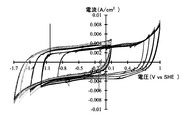
- 15 is a graph showing the results of cyclic voltammetry in Evaluation Example 4.
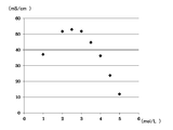
- 15 is a graph showing the results of evaluation of the electric double layer capacitor in Evaluation Example 5;
- 15 is a graph showing the results of cyclic voltammetry in Evaluation Example 6.
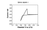
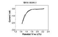
- 15 is a graph showing the results of cyclic voltammetry of a cell equipped with the electrolytic solution of Production Example 17 in Evaluation Example 7.
- 15 is a graph showing the results of cyclic voltammetry of a cell equipped with the electrolytic solution of Production Example 20 in Evaluation Example 7.
- 15 is a graph showing the results of cyclic voltammetry of a cell equipped with the electrolytic solution of Production Example 21 in Evaluation Example 7.
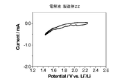
- it is a graph which shows the result of the cyclic voltammetry of the cell which comprises the electrolyte solution of manufacture example 22.
- the electrolyte for a storage battery of the present invention (hereinafter sometimes simply referred to as “the electrolyte of the present invention”) is a water-based electrolyte. Therefore, the main solvent used in the storage battery electrolyte of the present invention is water. However, the solvent may be a mixed solvent containing water and other non-aqueous solvents.
- non-aqueous solvents are soluble in water and, for example, alcohols such as methanol, and acetone, acetonitrile, dimethyl sulfoxide or dimethyl carbonate, ethyl methyl carbonate, diethyl carbonate, ethylene carbonate, propylene Mention may be made of aprotic polar solvents such as carbonates such as carbonate. Even in the case of such a mixed solvent, the proportion of water is preferably 90% or more by volume.
- the alkali metal salt used in the electrolytic solution for a storage battery device of the present invention is preferably a lithium salt or a sodium salt, but a salt of a metal belonging to Group 2 such as magnesium can also be used.
- the cationic species of the alkali metal salt may be selected according to the type of charge carrier of the storage battery using the electrolytic solution of the present invention. For example, when the secondary battery is a lithium ion secondary battery, a lithium salt is preferable, and when the secondary battery is a sodium ion secondary battery, a sodium salt is preferable.
- the mixture which combined two or more types of alkali metal salts can also be used.
- the anion constituting the alkali metal salt is preferably an organic anion containing a carbon atom in the structure.
- R 1 SO 2 (R 2 SO 2 ) N - General formula (1)
- R 1 and R 2 are each independently selected from an alkyl group or a halogen-substituted alkyl group. R 1 and R 2 may combine with each other to form a ring
- R 3 SO 3 - General formula (2) (R 3 is selected from an alkyl group or a halogen-substituted alkyl group.)
- R 4 CO 2 - General formula (3) (R 4 is selected from an alkyl group or a halogen-substituted alkyl group.)
- the carbon number n of the alkyl group or the halogen-substituted alkyl group is preferably 1 to 6, more preferably 1 to 3, and still more preferably 1 to 2.
- a halogen of the halogen substituted alkyl group fluorine is preferable.
- the number of halogen substitution in the halogen-substituted alkyl group is equal to or less than the number of hydrogen in the original alkyl group.
- R 1 to R 4 are each represented by the following general formula (1-1).
- General formula (1-1) (N is an integer of 1 or more.
- an organic anion having a fluoroalkyl group is preferable.
- TFSA bis (trifluoromethanesulfonyl) amide
- BETA bis (perfluoro ethanesulfonyl) amide
- BETA bis (perfluoroethanesulfonyl) (trifluoromethanesulfonyl) amide
- N (C 2 F 5 SO 2 ) (CF 3 SO 2 )] ⁇ is preferable.
- alkali metal salt examples include lithium bis (trifluoromethanesulfonyl) amide (LiTFSA), lithium bis (perfluoroethanesulfonyl) amide (LiBETA), lithium (perfluoroethanesulfonyl) (trifluoromethanesulfonyl) amide Sodium bis (trifluoromethanesulfonyl) amide (NaTFSA), sodium bis (perfluoroethanesulfonyl) amide (NaBETA), and sodium (perfluoroethanesulfonyl) (trifluoromethanesulfonyl) amide.
- CF 3 SO 3 ⁇ C 2 F 5 SO 3 ⁇ , CF 3 CO 2 ⁇ and C 2 F 5 CO 2 ⁇ can be exemplified.
- alkali metal salts include CF 3 SO 3 Li, C 2 F 5 SO 3 Li, CF 3 CO 2 Li, C 2 F 5 CO 2 Li, CF 3 SO 3 Na, C 2 F 5 SO 3 Na, CF 3 CO 2 Na , and C 2 F 5 CO 2 Na can be exemplified.
- the electrolytic solution for a storage battery device of the present invention is characterized in that it contains an alkali metal salt having a relatively high concentration.
- the mixing ratio of the alkali metal salt to the solvent in the electrolytic solution of the present invention is more than 4 mol to 15 mol or less of the solvent, preferably 4 to 10 mol or less of the solvent per 1 mol of the alkali metal salt.
- one aspect of the electrolytic solution of the present invention is an electrolytic solution for a storage battery containing water as a solvent, and the concentration of the alkali metal salt is 2.5 to 4.5 mol / L. It can also be expressed as The concentration of the alkali metal salt is preferably 2.5 to 4.0 mol / L, more preferably 2.5 to 3.5 mol / L, from the viewpoint of ion conductivity. The concentration of the alkali metal salt is preferably 2.6 to 4.1 mol / L, more preferably 3.1 to 3.6 mol / L, from the viewpoint of stability at low temperatures. Considered comprehensively, the concentration of the alkali metal salt is particularly preferably in the range of 3.1 to 3.5 mol / L.
- the electrolytic solution of the present invention is an electrolytic solution for a storage battery containing water as a solvent, and the amount of water is more than 4 mol to 15 mol or less with respect to 1 mol of alkali metal salt. You can also figure out what is.
- the electrolyte for a storage battery device of the present invention has a potential window exceeding that of pure water (stable potential region) by using an alkali metal salt having a relatively high concentration, and is preferably 1.2 V or more, more preferably Has a potential window of about 1.3 V or more, more preferably about 1.5 V.
- supporting electrolytes known in the art can be included.
- a supporting electrolyte is, for example, LiPF 6 , LiBF 4 , LiClO 4 , LiNO 3 , LiCl, Li 2 SO 4, Li 2 S, etc., and the like when the secondary battery is a lithium ion secondary battery. What is chosen from arbitrary combinations is mentioned.
- the electrolyte for a storage battery device of the present invention can also contain other components as necessary for the purpose of improving its function and the like.
- Other components include, for example, conventionally known overcharge inhibitors, deoxidizers, and property improving assistants for improving capacity retention characteristics after high temperature storage and cycle characteristics.
- the content of the overcharge inhibitor in the electrolyte is preferably 0.01 to 5% by mass.
- the electrolytic solution contains 0.1% by mass or more of the overcharge preventing agent, it becomes easier to suppress the explosion and the ignition of the electricity storage device due to the overcharge, and the electricity storage device can be used more stably.
- property improvement aids for improving the capacity retention characteristics and cycle characteristics after high temperature storage include succinic anhydride, glutaric anhydride, maleic anhydride, citraconic anhydride, glutaconic anhydride, itaconic anhydride, diasteric anhydride, and the like.
- Carboxylic acid anhydrides such as glycolic acid, cyclohexanedicarboxylic acid anhydride, cyclopentanetetracarboxylic acid dianhydride, phenylsuccinic acid anhydride; ethylene sulfite, 1,3-propane sultone, 1,4-butane sultone, methanesulfonic acid Methyl, busulfan, sulfolane, sulfolene, dimethyl sulfone, diphenyl sulfone, methylphenyl sulfone, dibutyl disulfide, dicyclohexyl disulfide, tetramethylthiuram monosulfide, N, N-dimethylmethanesulfonamide, N, N-diethylmethane Sulfur-containing compounds such Ruhon'amido the like.
- One of these property improving auxiliaries may be used alone, or two or more thereof may be used
- the power storage device of the present invention comprises a positive electrode and a negative electrode, and the electrolytic solution of the present invention.
- a power storage device a secondary battery and a capacitor can be exemplified.
- Negative electrode As a negative electrode in the power storage device of the present invention, an electrode configuration known in the relevant technical field can be used.
- a negative electrode active material capable of electrochemically absorbing and desorbing lithium ions can be mentioned.
- known negative electrode active materials for lithium ion secondary batteries can be used.
- natural graphite (graphite), Highly Oriented Graphitic Graphite (HOPG), amorphous Carbonaceous materials such as carbon can be mentioned.
- Still other examples include alloys containing lithium element, metal oxides, metal sulfides, and metal compounds such as metal nitrides.
- lithium aluminum alloy, lithium tin alloy, lithium lead alloy, lithium silicon alloy etc. can be mentioned, for example.
- the metal oxide having a lithium element can be, for example, lithium titanate (Li 4 Ti 5 O 12, etc.) and the like.
- a metal nitride containing a lithium element lithium cobalt nitride, lithium iron nitride, lithium manganese nitride etc. can be mentioned, for example.
- sulfur-based compounds can also be exemplified.
- a metal such as iron or zinc may be used for the negative electrode.
- These negative electrode active materials may be used alone or in combination of two or more. Among them, lithium titanate is preferable as the negative electrode active material in the case of a lithium ion secondary battery.
- an electrode containing a negative electrode active material capable of electrochemically absorbing and desorbing sodium ions can be used.
- sodium metal instead of lithium metal described above, etc.
- an alloy containing a sodium element, a metal oxide, a metal sulfide, a metal compound such as a metal nitride can be used.
- the polarizable electrode material is included in the negative electrode.
- a polarizable electrode material what is used for a normal electric double layer capacitor should just be used, and the activated carbon manufactured from various raw materials can be illustrated.
- the activated carbon preferably has a large specific surface area.
- the negative electrode includes a material capable of inserting and extracting lithium ions or sodium ions.
- a material capable of inserting and extracting lithium ions or sodium ions.
- graphite containing materials such as natural graphite or artificial graphite, can be illustrated.
- a material such as lithium titanate may be used which exhibits a redox capacity at a constant potential by inserting and desorbing a cation such as lithium ion.
- the negative electrode active material contains no ion contributing to oxidation / reduction, for example, in the case of a lithium ion capacitor, when using a material not containing lithium as the negative electrode active material, the negative electrode or positive electrode contains a compound containing a large amount of lithium metal or lithium. Or the like, from which lithium is previously doped in the negative electrode active material may be used.
- the negative electrode may contain only the negative electrode active material, and in addition to the negative electrode active material, contains at least one of a conductive material and a binder.
- the negative electrode mixture may be attached to a negative electrode current collector.
- the negative electrode active material is foil-like, it can be a negative electrode containing only the negative electrode active material.
- the negative electrode active material is in the form of powder, it can be a negative electrode having the negative electrode active material and a binder.
- a doctor blade method, a molding method using a pressure bonding press, or the like can be used as a method of forming a negative electrode using a powdery negative electrode active material. The same applies to the case where the power storage device is a capacitor.
- conductive materials such as carbon materials and metal fibers, metal powders such as copper, silver, nickel and aluminum, and organic conductive materials such as polyphenylene derivatives can be used.
- carbon material graphite, soft carbon, hard carbon, carbon black, ketjen black, acetylene black, graphite, activated carbon, carbon nanotube, carbon fiber and the like can be used.
- synthetic resins containing an aromatic ring, mesoporous carbon obtained by firing petroleum pitch or the like can also be used.
- a fluorine-based resin such as polyvinylidene fluoride (PVDF), polytetrafluoroethylene (PTFE), ethylene tetrafluoroethylene (ETFE) or the like, polyethylene, polypropylene or the like can be preferably used.
- PVDF polyvinylidene fluoride
- PTFE polytetrafluoroethylene
- ETFE ethylene tetrafluoroethylene
- polyethylene polypropylene or the like
- the negative electrode current collector it is possible to use a rod-like body, a plate-like body, a foil-like body, a net-like body or the like mainly composed of a metal such as copper, nickel, aluminum, zinc, titanium, platinum or stainless steel.
- Positive electrode As a positive electrode of the electricity storage device of the present invention, an electrode configuration known in the relevant technical field can be used.
- the power storage device is a lithium ion secondary battery
- LiMn 2 O 4 lithium manganate
- LiNiO 2 lithium nickelate
- LiNi LiNi .
- the positive electrode may contain a conductive material and a binder.
- an oxygen-containing metal salt such as oxygen or lithium oxide may be employed as the positive electrode active material.
- the positive electrode which comprises this positive electrode active material may contain the catalyst which promotes the oxidation-reduction reaction of oxygen in this positive electrode active material.
- the transition metal oxide (The said transition metal is manganese, cobalt, iron, nickel, copper, for example) which contains lithium excess can be illustrated.
- a high specific surface area material such as activated carbon can also be used in the positive electrode in order to create a reaction field for efficiently redoxing the oxygen in the air and extracting the capacity.
- the power storage device is a sodium ion secondary battery
- a known positive electrode active material can be used.
- the polarizable electrode material is contained in the positive electrode.
- the polarizable electrode material those described for the negative electrode may be employed.
- the polarizable electrode material may be a conductive polymer such as polyacene or a redox which increases capacity by adsorption and desorption of anion such as 2,2,6,6-tetramethylpiperidine-N-oxyl (TEMPO). You may use the material used for a capacitor.
- TEMPO 2,2,6,6-tetramethylpiperidine-N-oxyl
- a material such as lithium manganate having a spinel structure or lithium iron phosphate having an olivine structure may be included, which exhibits a redox capacity at a constant potential of 3 V or more by inserting and desorbing a cation such as lithium ion.
- conductive material and the binder those similar to the above-mentioned negative electrode can be used.
- MnO 2 , Fe 2 O 3 , NiO, CuO, Pt, Co or the like can be used as a catalyst for promoting the oxidation-reduction reaction of oxygen.
- the binder the same binder as that of the above-mentioned negative electrode can be used.
- the positive electrode current collector it is possible to use a rod-like body mainly made of a metal such as nickel, aluminum, titanium, platinum or stainless steel, a plate-like body, a foil-like body, a net-like body or the like.
- the positive electrode active material is oxygen
- the positive electrode current collector is a porous metal such as mesh (grid), sponge (foamed) metal, punched metal, expanded metal, etc., in order to increase the diffusion of oxygen.
- the body is used.
- the metal is, for example, copper, nickel, aluminum, stainless steel or the like.
- the separator used in the power storage device of the present invention is not particularly limited as long as it has a function of electrically separating the positive electrode layer and the negative electrode layer, and examples thereof include polyethylene (PE), Examples thereof include porous insulating materials such as porous sheets made of resins such as polypropylene (PP), polyester, cellulose, and polyamide, and nonwoven fabrics such as non-woven fabrics and glass fiber non-woven fabrics.
- PE polyethylene
- porous insulating materials such as porous sheets made of resins such as polypropylene (PP), polyester, cellulose, and polyamide
- nonwoven fabrics such as non-woven fabrics and glass fiber non-woven fabrics.
- the shape of the power storage device of the present invention is not particularly limited as long as it can accommodate the positive electrode, the negative electrode, and the electrolytic solution, but, for example, cylindrical, coin, flat, laminate, etc. Can be mentioned.
- the case for housing the power storage device may be an open air case or a closed case.
- the open-air battery case has a vent port through which air can flow in and out, and the air can be in contact with the positive electrode.
- the battery case is a sealed battery case
- the gas to be supplied / discharged is preferably a dry gas, and in particular, the oxygen concentration is preferably high, and pure oxygen (99.99%) is more preferable. Further, it is preferable to increase the oxygen concentration at the time of discharge and lower the oxygen concentration at the time of charge.
- electrolyte solution and secondary battery of this invention are suitable for the use as a secondary battery, using as a primary battery is not excluded.
- LiTFSA as an alkali metal salt was dissolved in water to prepare an aqueous solution having a LiTFSA concentration of 5.13 mol / L. This aqueous solution was used as the electrolytic solution of Production Example 1.
- the electrolytic solution of Production Example 1 contains water in an amount of 2.7 mol with respect to 1 mol of LiTFSA.
- Production Example 8 Three parts by volume of the electrolyte solution of Production Example 1 and 7 parts by volume of water were mixed to prepare an aqueous solution having a LiTFSA concentration of 1.54 mol / L. This aqueous solution was used as an electrolyte of Production Example 8.
- the electrolytic solution of Production Example 8 contains 28.0 mol of water per 1 mol of LiTFSA.
- Production Example 9 Two parts by volume of the electrolyte solution of Production Example 1 and eight parts by volume of water were mixed to prepare an aqueous solution having a LiTFSA concentration of 1.03 mol / L. This aqueous solution was used as an electrolytic solution of Production Example 9.
- the electrolytic solution of Production Example 9 contains water at 46.0 mol with respect to 1 mol of LiTFSA.
- Production Example 10 One part by volume of the electrolytic solution of Production Example 1 and 9 parts by volume of water were mixed to prepare an aqueous solution having a concentration of LiTFSA of 0.51 mol / L. This aqueous solution was used as the electrolyte of Production Example 10.
- the electrolytic solution of Production Example 10 contains water at 100.2 mol with respect to 1 mol of LiTFSA.
- Production Example 12 LiTFSA as an alkali metal salt was dissolved in water to prepare an aqueous solution having a LiTFSA concentration of 1.00 mol / L. This aqueous solution was used as the electrolyte of Production Example 12.
- the electrolytic solution of Production Example 12 contains 47.4 mol of water per 1 mol of LiTFSA.
- Production Example 13 LiTFSA as an alkali metal salt was dissolved in water to prepare an aqueous solution in which the concentration of LiTFSA was 2.00 mol / L. This aqueous solution was used as the electrolyte of Production Example 13.
- the electrolytic solution of Production Example 13 contains 19.6 mol of water per 1 mol of LiTFSA.
- Production Example 14 LiTFSA as an alkali metal salt was dissolved in water to prepare an aqueous solution in which the concentration of LiTFSA was 2.50 mol / L. This aqueous solution was used as the electrolyte of Production Example 14.
- the electrolytic solution of Production Example 14 contains 14.1 mol of water per 1 mol of LiTFSA.
- Production Example 15 Example 7 LiTFSA as an alkali metal salt was dissolved in water to prepare an aqueous solution in which the concentration of LiTFSA was 3.00 mol / L. This aqueous solution was used as an electrolytic solution of Production Example 15. The electrolytic solution of Production Example 15 contains 10.4 mol of water per 1 mol of LiTFSA.
- Production Example 17 Example 9 LiTFSA as an alkali metal salt was dissolved in water to prepare an aqueous solution having a LiTFSA concentration of 4.00 mol / L. This aqueous solution was used as an electrolytic solution of Production Example 17. The electrolytic solution of Production Example 17 contains 5.7 mol of water per 1 mol of LiTFSA.
- LiTFSA as an alkali metal salt was dissolved in water to prepare an aqueous solution having a LiTFSA concentration of 4.50 mol / L. This aqueous solution was used as an electrolytic solution of Production Example 18.
- the electrolytic solution of Production Example 18 contains 4.2 mol of water per 1 mol of LiTFSA.
- Production Example 19 LiTFSA as an alkali metal salt was dissolved in water to prepare an aqueous solution having a concentration of 5.00 mol / L of LiTFSA. This aqueous solution was used as an electrolytic solution of Production Example 19. The electrolytic solution of Production Example 19 contains water in an amount of 2.9 mol per 1 mol of LiTFSA.
- Production Example 21 An aqueous solution in which LiTFSA as a alkali metal salt and LiBETA are mixed at a molar ratio of 7: 3 to form a mixture, and the mixture is added to water so that the value of (number of moles of water) / (number of moles of alkali metal salt) becomes 50. was prepared. This aqueous solution was used as an electrolytic solution of Production Example 21.
- Production Example 22 An aqueous solution having a value of (number of moles of water) / (number of moles of alkali metal salt) of 19 was prepared by adding to water Li 2 SO 4 as an alkali metal salt. This aqueous solution was used as the electrolyte of Production Example 22.
- Example 12 An aqueous solution in which the value of (number of moles of water) / (number of moles of alkali metal salt) was 4.5 was prepared by adding to LiNO 3 as an alkali metal salt to water. This aqueous solution was used as an electrolytic solution of Production Example 23.
- Table 1 shows a list of electrolytes. Blank means not calculated.
- Electrolyte solution Electrolyte solution of Production Example 11
- Working electrode Electrode for electric double layer capacitor comprising a mixture layer containing 86% by mass of activated carbon and Al foil (manufactured by Hohsen Co., Ltd .: density of mixture layer is 0.63 g / cm 3 ))
- Reference electrode Ag / AgCl (saturated KCl)
- Counter electrode platinum
- Positive electrode An electrode for an electric double layer capacitor comprising a mixture layer containing 86% by mass of activated carbon and an Al foil (manufactured by Hohsen Co., Ltd .: the density of the mixture layer is 0.63 g / cm 3 )
- Negative electrode An electrode for an electric double layer capacitor comprising a mixture layer containing 86% by mass of activated carbon and an Al foil (manufactured by Hohsen Co., Ltd .: density of mixture layer is 0.63 g / cm 3 )
- Electrolyte Electrolyte of Production Example 11
- the electric double layer capacitor was charged and discharged 10 times in a voltage range of 0 to 1 V at a current of 10 mA / g, and this was taken as conditioning.
- charging / discharging in each voltage range at each charging / discharging current shown below was repeated five times, respectively.
- an electric double layer capacitor having the same configuration as that described above was manufactured except that the electrolytic solution of Production Example 1 was used as the electrolytic solution, and a capacitor of Comparative Example A was obtained.
- the capacitor of Comparative Example A was charged / discharged in the voltage range of 0 to 1.2 V under the same conditions as above.
- the range of the five small arrows is, from the left, a charge current of 100 mA / g, 500 mA / g, 1000 mA / g, 2000 mA / g, about It means 3600 mA / g.
- the capacitor of Example A suitably charges and discharges under any current condition and in any voltage range. Further, when the capacitance of the capacitor of Example A and the capacitance of the capacitor of Comparative Example A in the voltage range of 0 to 1.2 V were compared, it was found that the capacitor of Example A was superior. It was confirmed that the electrolytic solution of the present invention is excellent.
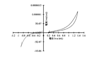
- Electrolyte solution Electrolyte solution of Production Example 11
- Working electrode Four stacked aluminum foils with an area of 1 cm 2 and a thickness of 15 ⁇ m
- Reference electrode Ag / AgCl (saturated KCl)
- Counter electrode Platinum
- the electrolytic solution of the present invention does not cause any particular decomposition of the solvent in the presence of aluminum and does not cause any particular corrosion to aluminum. It was supported that the electrolytic solution of the present invention can be suitably used also for a power storage device provided with a current collector made of aluminum.
- Electrolyte solution Production Example 17, Production Example 20, Production Example 21 or Production Example 22
- Working electrode An electrode composed of a negative electrode mixture layer containing 85% by mass of Li 4 Ti 5 O 12 , 5% by mass of PVDF and 10% by mass of acetylene black, and a current collector made of Zn.
- Electrode composed of a mixture layer containing 10% by weight of LiMn 2 O 4 , 10% by weight of PVDF and 5% by weight of acetylene black and a current collector made of Ti
- the secondary battery provided with the electrolytic solution of the present invention is reversibly operable.
Landscapes
- Chemical & Material Sciences (AREA)
- Chemical Kinetics & Catalysis (AREA)
- Electrochemistry (AREA)
- Engineering & Computer Science (AREA)
- Power Engineering (AREA)
- General Chemical & Material Sciences (AREA)
- Microelectronics & Electronic Packaging (AREA)
- Inorganic Chemistry (AREA)
- Materials Engineering (AREA)
- Manufacturing & Machinery (AREA)
- Secondary Cells (AREA)
- Electric Double-Layer Capacitors Or The Like (AREA)
- Cell Electrode Carriers And Collectors (AREA)
Abstract
水を溶媒として含む蓄電装置用電解液であって、アルカリ金属塩1molに対して溶媒量が4mol超~15mol以下であることを特徴とする、該電解液。
Description
本発明は、蓄電装置用の水系電解液、及び当該水系電解液を含む蓄電装置に関する。
リチウムイオン二次電池は、従来の二次電池と比較して大きな理論エネルギー密度を有していることから、携帯機器や電気自動車用のバッテリーとして広く用いられている。従来のリチウムイオン二次電池では、高エネルギー密度を達成するため、約4Vの電圧でも分解しない有機溶媒系の電解液が使用されている。そのような有機溶媒としては、典型的には、エチレンカーボネートやジエチルカーボネート等が主として用いられている(特許文献1)。
しかし、有機溶媒は一般に可燃性であり、特に自動車や電力貯蔵用途の大型二次電池では安全性の確保が重要課題となっている。また有機溶媒溶液のイオン伝導度は水溶液と比べると極めて低く、急速な充電・放電特性が十分ではない点も問題となっている。一方で、このような問題に鑑みて、水溶液を電解液として用いた水系リチウムイオン二次電池の研究が行われてきているが、水は理論的には1.23Vの電圧で分解してしまうため、当該電圧以上の高電圧でも安定作動する水系リチウムイオン二次電池はこれまでに達成されていない。
キャパシタは、電極表面に対する電解液中のイオンの吸着又は脱離により、電荷を蓄え又は電荷を放出する蓄電装置である。キャパシタにおいては、電解液に有機溶媒と4級アンモニウム塩等を用いる有機溶媒系キャパシタと、電解液の溶媒に水を用いる水系キャパシタに大別される。
キャパシタに蓄えられる電荷量は、静電容量と電圧の積で表される。そして、水系キャパシタにおいては、水の耐電圧の関係で電圧の上限が制限されるため、電荷量の増大のためには、静電容量を増加させる検討を行うのが一般的である。
実際に、特許文献2では、キャパシタの電極に用いる活性炭の細孔径及び比表面積を最適化して、静電容量を増加させる水系キャパシタの技術が開示されている。
しかし、上述したように、水の耐電圧が低いため、高電圧で安定作動する水系キャパシタの実用化は困難であった。
そこで、本発明は、リチウムイオン二次電池等の二次電池及びキャパシタなどの蓄電装置における新たな水系電解液を提供すること、並びに、比較的高電圧でも安定作動する水系電解液を用いた蓄電装置を提供することを課題とするものである。
本発明者らは、上記課題を解決するべく鋭意検討を行った結果、アルカリ金属塩1molに対して溶媒の量が4mol以下である、高濃度のアルカリ金属塩を含む水溶液である電解液が、純水の理論電位窓(安定電位領域)である1.23Vを大きく超える2V以上の電位窓を有すること、及び、かかる電解液を用いる水系蓄電装置が高い電圧下で可逆的に動作できることを見出した。その技術内容は、特願2015-4889で報告中である。
本発明者のさらなる検討の結果、前段落に記載の濃度以外の水溶液であっても、1.23Vを超える電位窓を有することを見出し、本発明を完成するに至った。
すなわち、本発明の電解液は、水を溶媒として含む蓄電装置用電解液であって、アルカリ金属塩1molに対して溶媒量が4mol超~15mol以下であることを特徴とする。
本発明によれば、高濃度のアルカリ金属塩、特に有機アニオンとアルカリ金属カチオンとのアルカリ金属塩を含む水溶液を電解液として用いることによって、従来の水系電解液では困難であった1.23Vを超える高電圧でも安定作動する水系電解液を用いたリチウムイオン二次電池やナトリウムイオン二次電池等の二次電池やキャパシタなどの水系蓄電装置を提供することができる。
加えて、本発明の電解液は、極めて安価な溶媒である水と、従来の電解液中における成分として用いられているLiTFSA等の有機塩の組み合わせによる電解液であることから、そのコスト面でも優れており、さらに、後述の実施例で示すように、既存の有機電解液を用いたリチウムイオン二次電池やキャパシタとして実用化されている電極構成に対して適用可能であるため、その実用化への障壁は極めて低いものである。
以下、本発明の実施形態について説明する。本発明の範囲はこれらの説明に拘束されることはなく、以下の例示以外についても、本発明の趣旨を損なわない範囲で適宜変更し実施することができる。
1.電解液
(1)溶媒
本発明の蓄電装置用電解液(以下、単に「本発明の電解液」ということがある。)は、水系電解液であることを特徴とする。したがって、本発明の蓄電装置用電解液において用いられる主溶媒は、水である。ただし、溶媒を、水及びその他の非水溶媒を含む混合溶媒とすることも可能である。そのような非水溶媒は、水に可溶なものであり、例えば、メタノール等のアルコール類、並びに、アセトン、アセトニトリル、ジメチルスルホキシド、又は、ジメチルカーボネート、エチルメチルカーボネート、ジエチルカーボネート、エチレンカーボネート、プロピレンカーボネート等のカーボネート類等の非プロトン性極性溶媒を挙げることができる。かかる混合溶媒の場合でも、水の割合は体積比で90%以上であることが好ましい。
(2)アルカリ金属塩
本発明の蓄電装置用電解液において用いられるアルカリ金属塩は、好ましくは、リチウム塩、ナトリウム塩であるが、マグネシウム等第2族に属する金属の塩も用いることができる。アルカリ金属塩のカチオン種は、本発明の電解液を用いる蓄電装置の電荷担体の種類に応じて、選択すればよい。例えば、二次電池がリチウムイオン二次電池の場合にはリチウム塩が好ましく、二次電池がナトリウムイオン二次電池の場合にはナトリウム塩が好ましい。また、2種類以上のアルカリ金属塩を組み合わせた混合物を用いることもできる。
本発明の蓄電装置用電解液において用いられるアルカリ金属塩は、好ましくは、リチウム塩、ナトリウム塩であるが、マグネシウム等第2族に属する金属の塩も用いることができる。アルカリ金属塩のカチオン種は、本発明の電解液を用いる蓄電装置の電荷担体の種類に応じて、選択すればよい。例えば、二次電池がリチウムイオン二次電池の場合にはリチウム塩が好ましく、二次電池がナトリウムイオン二次電池の場合にはナトリウム塩が好ましい。また、2種類以上のアルカリ金属塩を組み合わせた混合物を用いることもできる。
当該アルカリ金属塩を構成するアニオンは、好ましくは炭素原子を構造内に含む有機アニオンである。
有機アニオンとしては、下記一般式(1)~一般式(3)で表されるものが好ましい。
(R1SO2)(R2SO2)N- 一般式(1)
(R1、R2は、それぞれ独立に、アルキル基又はハロゲン置換アルキル基から選択される。R1及びR2は互いに結合して環を形成してもよい。)
R3SO3 - 一般式(2)
(R3は、アルキル基又はハロゲン置換アルキル基から選択される。)
R4CO2 - 一般式(3)
(R4は、アルキル基又はハロゲン置換アルキル基から選択される。)
(R1SO2)(R2SO2)N- 一般式(1)
(R1、R2は、それぞれ独立に、アルキル基又はハロゲン置換アルキル基から選択される。R1及びR2は互いに結合して環を形成してもよい。)
R3SO3 - 一般式(2)
(R3は、アルキル基又はハロゲン置換アルキル基から選択される。)
R4CO2 - 一般式(3)
(R4は、アルキル基又はハロゲン置換アルキル基から選択される。)
上記一般式(1)~一般式(3)において、アルキル基又はハロゲン置換アルキル基の炭素数nは、1~6が好ましく、1~3がより好ましく、1~2がさらに好ましい。ハロゲン置換アルキル基のハロゲンとしては、フッ素が好ましい。ハロゲン置換アルキル基におけるハロゲン置換数は、もとのアルキル基の水素の数以下である。
R1~R4は、それぞれ、以下の一般式(1-1)で表される。
CnHaFbClcBrdIe 一般式(1-1)
(nは1以上の整数である。a、b、c、d、eは0以上の整数である。2n+1=a+b+c+d+eを満足する。)
CnHaFbClcBrdIe 一般式(1-1)
(nは1以上の整数である。a、b、c、d、eは0以上の整数である。2n+1=a+b+c+d+eを満足する。)
一般式(1-1)において、耐酸化性の観点から、aは小さい方が好ましく、a=0がより好ましく、2n+1=bが最も好ましい。
有機アニオンとしては、フルオロアルキル基を有する有機アニオンが好ましい。例えば、ビス(トリフルオロメタンスルホニル)アミド(TFSA;[N(CF3SO2)2]-)やビス(パーフルオロエタンスルホニル)アミド(BETA;[N(C2F5SO2)2]-)、(パーフルオロエタンスルホニル)(トリフルオロメタンスルホニル)アミド([N(C2F5SO2)(CF3SO2)]-)が好適である。
したがって、当該アルカリ金属塩の具体例としては、リチウムビス(トリフルオロメタンスルホニル)アミド(LiTFSA)、リチウムビス(パーフルオロエタンスルホニル)アミド(LiBETA)、リチウム(パーフルオロエタンスルホニル)(トリフルオロメタンスルホニル)アミド、ナトリウムビス(トリフルオロメタンスルホニル)アミド(NaTFSA)、ナトリウムビス(パーフルオロエタンスルホニル)アミド(NaBETA)、及びナトリウム(パーフルオロエタンスルホニル)(トリフルオロメタンスルホニル)アミドが挙げられる。
他の好適な有機アニオンとしては、CF3SO3
-、C2F5SO3
-、CF3CO2
-、C2F5CO2
-を例示できる。
他のアルカリ金属塩の具体例としては、CF3SO3Li、C2F5SO3Li、CF3CO2Li、C2F5CO2Li、CF3SO3Na、C2F5SO3Na、CF3CO2Na、C2F5CO2Naを例示できる。
また、本発明の蓄電装置用電解液は、比較的高濃度のアルカリ金属塩を含むことを特徴とするものである。これによって、従来は、水系電解液では可逆的に作動し得なかった電極構成においても、高い電圧を発生する二次電池などの蓄電装置を実現することができる。
本発明の電解液中におけるアルカリ金属塩と溶媒の混合比は、アルカリ金属塩1molに対して溶媒4mol超~15mol以下であり、好ましくは、溶媒4mol超~10mol以下である。
また、本明細書の記載から、本発明の電解液の一態様は、水を溶媒として含む蓄電装置用電解液であって、アルカリ金属塩の濃度が2.5~4.5mol/Lであると表現することもできる。アルカリ金属塩の濃度は、イオン伝導度の観点からは、2.5~4.0mol/Lが好ましく、2.5~3.5mol/Lがより好ましい。また、アルカリ金属塩の濃度は、低温での安定性の観点からは、2.6~4.1mol/Lが好ましく、3.1~3.6mol/Lがより好ましい。総合的に考察すると、アルカリ金属塩の濃度は、3.1~3.5mol/Lの範囲内が特に好ましい。
さらに、本明細書の記載から、本発明の電解液の他の態様として、水を溶媒として含む蓄電装置用電解液であって、アルカリ金属塩1molに対して水の量が4mol超~15mol以下であるものを把握することもできる。
本発明の蓄電装置用電解液は、比較的高濃度のアルカリ金属塩を用いることにより、純水の電位窓(安定電位領域)を超える電位窓を有し、好ましくは1.2V以上、より好ましくは1.3V以上、さらに好ましくは1.5V程度の電位窓を有する。
上述したアルカリ金属塩に加えて、当該技術分野において公知の支持電解質を含むことができる。そのような支持電解質は、例えば、二次電池がリチウムイオン二次電池である場合には、LiPF6、LiBF4、LiClO4、LiNO3、LiCl、Li2SO4及びLi2S等及びこれらの任意の組み合わせから選択されるものが挙げられる。
(3)その他の成分
また、本発明の蓄電装置用電解液は、その機能の向上等の目的で、必要に応じて他の成分を含むこともできる。他の成分としては、例えば、従来公知の過充電防止剤、脱酸剤、高温保存後の容量維持特性およびサイクル特性を改善するための特性改善助剤が挙げられる。
また、本発明の蓄電装置用電解液は、その機能の向上等の目的で、必要に応じて他の成分を含むこともできる。他の成分としては、例えば、従来公知の過充電防止剤、脱酸剤、高温保存後の容量維持特性およびサイクル特性を改善するための特性改善助剤が挙げられる。
当該電解液が過充電防止剤を含有する場合、電解液中の過充電防止剤の含有量は、0.01~5質量%であることが好ましい。電解液に過充電防止剤を0.1質量%以上含有させることにより、過充電による蓄電装置の破裂・発火を抑制することがさらに容易になり、蓄電装置をより安定に使用できる。
高温保存後の容量維持特性やサイクル特性を改善するための特性改善助剤としては、例えば、無水コハク酸、無水グルタル酸、無水マレイン酸、無水シトラコン酸、無水グルタコン酸、無水イタコン酸、無水ジグリコール酸、シクロヘキサンジカルボン酸無水物、シクロペンタンテトラカルボン酸二無水物、フェニルコハク酸無水物等のカルボン酸無水物;エチレンサルファイト、1,3-プロパンスルトン、1,4-ブタンスルトン、メタンスルホン酸メチル、ブスルファン、スルホラン、スルホレン、ジメチルスルホン、ジフェニルスルホン、メチルフェニルスルホン、ジブチルジスルフィド、ジシクロヘキシルジスルフィド、テトラメチルチウラムモノスルフィド、N,N-ジメチルメタンスルホンアミド、N,N-ジエチルメタンスルホンアミド等の含硫黄化合物などが挙げられる。これら特性改善助剤は、1種を単独で用いてもよく、2種以上を併用してもよい。電解液が特性改善助剤を含有する場合、電解液中の特性改善助剤の含有量は、0.01~5質量%であることが好ましい。
2.蓄電装置
本発明の蓄電装置は、正極及び負極と、本発明の電解液を備えるものである。蓄電装置としては、二次電池、キャパシタを例示できる。
本発明の蓄電装置は、正極及び負極と、本発明の電解液を備えるものである。蓄電装置としては、二次電池、キャパシタを例示できる。
(1)負極
本発明の蓄電装置における負極としては、当該技術分野において公知の電極構成を用いることができる。例えば、蓄電装置がリチウムイオン二次電池の場合には、電気化学的にリチウムイオンを吸蔵・放出できる負極活物質を含む電極が挙げられる。このような負極活物質としては、公知のリチウムイオン二次電池用負極活物質を用いることができ、例えば、天然グラファイト(黒鉛)、高配向性グラファイト(Highly Oriented Pyrolytic Graphite;HOPG)、非晶質炭素等の炭素質材料が挙げられる。さらに他の例として、リチウム元素を含む合金や金属酸化物、金属硫化物、金属窒化物のような金属化合物が挙げられる。例えば、リチウム元素を有する合金としては、例えばリチウムアルミニウム合金、リチウムスズ合金、リチウム鉛合金、リチウムケイ素合金等を挙げることができる。また、リチウム元素を有する金属酸化物としては、例えばチタン酸リチウム(Li4Ti5O12等)等を挙げることができる。また、リチウム元素を含有する金属窒化物としては、例えばリチウムコバルト窒化物、リチウム鉄窒化物、リチウムマンガン窒化物等を挙げることができる。さらに、硫黄系化合物を例示することもできる。また、鉄や亜鉛などの金属を負極に用いてもよい。これら負極活物質は、1種を単独で用いてもよく、2種以上を併用してもよい。なかでも、リチウムイオン二次電池の場合の負極活物質としては、チタン酸リチウムが好ましい。
本発明の蓄電装置における負極としては、当該技術分野において公知の電極構成を用いることができる。例えば、蓄電装置がリチウムイオン二次電池の場合には、電気化学的にリチウムイオンを吸蔵・放出できる負極活物質を含む電極が挙げられる。このような負極活物質としては、公知のリチウムイオン二次電池用負極活物質を用いることができ、例えば、天然グラファイト(黒鉛)、高配向性グラファイト(Highly Oriented Pyrolytic Graphite;HOPG)、非晶質炭素等の炭素質材料が挙げられる。さらに他の例として、リチウム元素を含む合金や金属酸化物、金属硫化物、金属窒化物のような金属化合物が挙げられる。例えば、リチウム元素を有する合金としては、例えばリチウムアルミニウム合金、リチウムスズ合金、リチウム鉛合金、リチウムケイ素合金等を挙げることができる。また、リチウム元素を有する金属酸化物としては、例えばチタン酸リチウム(Li4Ti5O12等)等を挙げることができる。また、リチウム元素を含有する金属窒化物としては、例えばリチウムコバルト窒化物、リチウム鉄窒化物、リチウムマンガン窒化物等を挙げることができる。さらに、硫黄系化合物を例示することもできる。また、鉄や亜鉛などの金属を負極に用いてもよい。これら負極活物質は、1種を単独で用いてもよく、2種以上を併用してもよい。なかでも、リチウムイオン二次電池の場合の負極活物質としては、チタン酸リチウムが好ましい。
蓄電装置がナトリウムイオン二次電池の場合には、電気化学的にナトリウムイオンを吸蔵・放出できる負極活物質を含む電極を用いることができ、例えば、上記のリチウム金属等に替えて、ナトリウム金属、又はナトリウム元素を含む合金や金属酸化物、金属硫化物、金属窒化物のような金属化合物を用いることができる。
蓄電装置が電気二重層キャパシタの場合は、分極性電極材料を負極に含む。分極性電極材料としては、通常の電気二重層キャパシタに用いられるものであればよく、種々の原料から製造した活性炭を例示できる。活性炭は、比表面積の大きなものが好ましい。
蓄電装置がリチウムイオンキャパシタ又はナトリウムイオンキャパシタの場合は、リチウムイオン又はナトリウムイオンを吸蔵及び放出し得る材料を負極に含む。当該材料として、天然黒鉛又は人造黒鉛などの黒鉛含有材料を例示できる。また、リチウムイオンなどのカチオンを挿入及び脱離して一定電位でレドックス容量を示す、チタン酸リチウムなどの材料を用いてもよい。負極活物質に酸化還元に寄与するイオンが含まれていない場合、たとえばリチウムイオンキャパシタの場合において、負極活物質にリチウムを含まない材料を用いる時には、金属リチウムやリチウムを多く含む化合物を負極もしくは正極に添加し、これらからリチウムを負極活物質に予めドープしたものを使用してもよい。
蓄電装置が二次電池の場合、上記負極は、負極活物質のみを含有するものであっても良く、負極活物質の他に、導電性材料および結着材(バインダ)の少なくとも一方を含有し、負極合材として負極集電体に付着させた形態であるものであっても良い。例えば、負極活物質が箔状である場合は、負極活物質のみを含有する負極とすることができる。一方、負極活物質が粉末状である場合は、負極活物質および結着材(バインダ)を有する負極とすることができる。粉末状の負極活物質を用いて負極を形成する方法としては、ドクターブレード法や圧着プレスによる成型方法等を用いることができる。蓄電装置がキャパシタの場合も同様である。
導電性材料としては、例えば、炭素材料、金属繊維等の導電性繊維、銅、銀、ニッケル、アルミニウム等の金属粉末、ポリフェニレン誘導体等の有機導電性材料を使用することができる。炭素材料として、黒鉛、ソフトカーボン、ハードカーボン、カーボンブラック、ケッチェンブラック、アセチレンブラック、グラファイト、活性炭、カーボンナノチューブ、カーボンファイバー等を使用することができる。また、芳香環を含む合成樹脂、石油ピッチ等を焼成して得られたメソポーラスカーボンを使用することもできる。
結着剤としては、例えば、ポリフッ化ビニリデン(PVDF)、ポリテトラフルオロエチレン(PTFE)、エチレンテトラフルオロエチレン(ETFE)等のフッ素系樹脂、或いは、ポリエチレン、ポリプロピレンなどを好ましく用いることができる。負極集電体としては、銅、ニッケル、アルミニウム、亜鉛、チタン、白金、ステンレススチール等の金属を主体とする棒状体、板状体、箔状体、網状体等を使用することができる。
(2)正極
本発明の蓄電装置の正極としては、当該技術分野において公知の電極構成を用いることができる。例えば、蓄電装置がリチウムイオン二次電池の場合には、正極活物質としては、コバルト酸リチウム(LiCoO2)、マンガン酸リチウム(LiMn2O4)、ニッケル酸リチウム(LiNiO2)、LiNi0.5Mn1.5O4等の1種類以上の遷移金属を含むリチウム含有遷移金属酸化物、遷移金属硫化物、金属酸化物、リン酸鉄リチウム(LiFePO4)やピロリン酸鉄リチウム(Li2FeP2O7)などの1種類以上の遷移金属を含むリチウム含有ポリアニオン系化合物、硫黄系化合物(Li2S)などが挙げられる。当該正極には、導電性材料や結着剤を含有してもよい。
本発明の蓄電装置の正極としては、当該技術分野において公知の電極構成を用いることができる。例えば、蓄電装置がリチウムイオン二次電池の場合には、正極活物質としては、コバルト酸リチウム(LiCoO2)、マンガン酸リチウム(LiMn2O4)、ニッケル酸リチウム(LiNiO2)、LiNi0.5Mn1.5O4等の1種類以上の遷移金属を含むリチウム含有遷移金属酸化物、遷移金属硫化物、金属酸化物、リン酸鉄リチウム(LiFePO4)やピロリン酸鉄リチウム(Li2FeP2O7)などの1種類以上の遷移金属を含むリチウム含有ポリアニオン系化合物、硫黄系化合物(Li2S)などが挙げられる。当該正極には、導電性材料や結着剤を含有してもよい。
また、正極活物質として酸素や酸化リチウムなどの酸素含有金属塩を採用してもよい。そして、かかる正極活物質を具備する正極は、かかる正極活物質における酸素の酸化還元反応を促進する触媒を含有してもよい。好ましい正極活物質としては、リチウムを過剰に含有する遷移金属酸化物(当該遷移金属は、例えばマンガン、コバルト、鉄、ニッケル、銅である。)を例示できる。また、大気中の酸素を効率よくレドックスさせて容量を取り出すための反応場を作り出すために、正極内に活性炭などの高比表面積材料を用いることもできる。
蓄電装置がナトリウムイオン二次電池の場合にも、同様に公知の正極活物質を用いることができる。
蓄電装置がキャパシタの場合は、分極性電極材料を正極に含有する。分極性電極材料としては、負極で説明したものを採用すればよい。また、分極性電極材料には、ポリアセンなどの導電性高分子や2,2,6,6-テトラメチルピペリジン-N-オキシル(TEMPO)のようにアニオンの吸脱着により容量が大きくなるようなレドックスキャパシタに使われる材料を用いても良い。また、リチウムイオンなどのカチオンを挿入及び脱離して3V以上の一定電位でレドックス容量を示す、スピネル構造のマンガン酸リチウムやオリビン構造のリン酸鉄リチウムなどの材料を含んでもよい。
導電性材料及び結着剤(バインダ)としては、上記負極と同様のものを用いることができる。
酸素の酸化還元反応を促進する触媒として、MnO2、Fe2O3、NiO、CuO、Pt、Co等を用いることができる。また、結着剤(バインダ)としては、上記負極と同様のバインダを用いることができる。
正極集電体としては、ニッケル、アルミニウム、チタン、白金、ステンレススチール等の金属を主体とする棒状体、板状体、箔状体、網状体等を使用することができる。また、正極活物質が酸素の場合は、正極集電体としては、酸素の拡散を高めるため、メッシュ(グリッド)状金属、スポンジ状(発泡)金属、パンチドメタル、エクスパンディドメタル等の多孔体が使用される。金属は、例えば、銅、ニッケル、アルミニウム、ステンレススチール等である。
(3)セパレータ
本発明の蓄電装置において用いられるセパレータとしては、正極層と負極層とを電気的に分離する機能を有するものであれば特に限定されるものではないが、例えばポリエチレン(PE)、ポリプロピレン(PP)、ポリエステル、セルロース、ポリアミド等の樹脂からなる多孔質シートや、不織布、ガラス繊維不織布等の不織布等の多孔質絶縁材料等を挙げることができる。
本発明の蓄電装置において用いられるセパレータとしては、正極層と負極層とを電気的に分離する機能を有するものであれば特に限定されるものではないが、例えばポリエチレン(PE)、ポリプロピレン(PP)、ポリエステル、セルロース、ポリアミド等の樹脂からなる多孔質シートや、不織布、ガラス繊維不織布等の不織布等の多孔質絶縁材料等を挙げることができる。
(4)形状等
本発明の蓄電装置の形状は、正極、負極、及び電解液を収納することができれば特に限定されるものではないが、例えば、円筒型、コイン型、平板型、ラミネート型等を挙げることができる。
本発明の蓄電装置の形状は、正極、負極、及び電解液を収納することができれば特に限定されるものではないが、例えば、円筒型、コイン型、平板型、ラミネート型等を挙げることができる。
また、蓄電装置を収納するケースは、大気開放型のケースであっても良く、密閉型のケースであっても良い。
なお、正極活物質が酸素である空気電池の場合について説明すると、大気開放型の電池ケースは、大気が出入りできる通風口を有し、大気が正極と接触可能な電池ケースである。一方、電池ケースが密閉型電池ケースとしては、密閉型電池ケースに、気体(空気)の供給管および排出管を設けることが好ましい。この場合、供給・排出する気体は、乾燥気体であることが好ましく、なかでも、酸素濃度が高いことが好ましく、純酸素(99.99%)であることがより好ましい。また、放電時には酸素濃度を高くし、充電時には酸素濃度を低くすることが好ましい。
なお、本発明の電解液及び二次電池は、二次電池としての用途に好適ではあるが、一次電池として用いることを除外するものではない。
以下、実施例などにより本発明をさらに詳細に説明するが、本発明はこれらによって限定されるものではない。
(製造例1)
アルカリ金属塩としてのLiTFSAを水に溶解して、LiTFSAの濃度が5.13mol/Lの水溶液を調製した。この水溶液を製造例1の電解液とした。製造例1の電解液には、1molのLiTFSAに対して、水が2.7molで含まれる。
アルカリ金属塩としてのLiTFSAを水に溶解して、LiTFSAの濃度が5.13mol/Lの水溶液を調製した。この水溶液を製造例1の電解液とした。製造例1の電解液には、1molのLiTFSAに対して、水が2.7molで含まれる。
(製造例2)
9容量部の製造例1の電解液と、1容量部の水を混合して、LiTFSAの濃度が4.62mol/Lの水溶液を調製した。この水溶液を製造例2の電解液とした。製造例2の電解液には、1molのLiTFSAに対して、水が3.9molで含まれる。
9容量部の製造例1の電解液と、1容量部の水を混合して、LiTFSAの濃度が4.62mol/Lの水溶液を調製した。この水溶液を製造例2の電解液とした。製造例2の電解液には、1molのLiTFSAに対して、水が3.9molで含まれる。
(製造例3:実施例1)
8容量部の製造例1の電解液と、2容量部の水を混合して、LiTFSAの濃度が4.10mol/Lの水溶液を調製した。この水溶液を製造例3の電解液とした。製造例3の電解液には、1molのLiTFSAに対して、水が5.4molで含まれる。
8容量部の製造例1の電解液と、2容量部の水を混合して、LiTFSAの濃度が4.10mol/Lの水溶液を調製した。この水溶液を製造例3の電解液とした。製造例3の電解液には、1molのLiTFSAに対して、水が5.4molで含まれる。
(製造例4:実施例2)
7容量部の製造例1の電解液と、3容量部の水を混合して、LiTFSAの濃度が3.59mol/Lの水溶液を調製した。この水溶液を製造例4の電解液とした。製造例4の電解液には、1molのLiTFSAに対して、水が7.3molで含まれる。
7容量部の製造例1の電解液と、3容量部の水を混合して、LiTFSAの濃度が3.59mol/Lの水溶液を調製した。この水溶液を製造例4の電解液とした。製造例4の電解液には、1molのLiTFSAに対して、水が7.3molで含まれる。
(製造例5:実施例3)
6容量部の製造例1の電解液と、4容量部の水を混合して、LiTFSAの濃度が3.08mol/Lの水溶液を調製した。この水溶液を製造例5の電解液とした。製造例5の電解液には、1molのLiTFSAに対して、水が9.9molで含まれる。
6容量部の製造例1の電解液と、4容量部の水を混合して、LiTFSAの濃度が3.08mol/Lの水溶液を調製した。この水溶液を製造例5の電解液とした。製造例5の電解液には、1molのLiTFSAに対して、水が9.9molで含まれる。
(製造例6:実施例4)
5容量部の製造例1の電解液と、5容量部の水を混合して、LiTFSAの濃度が2.57mol/Lの水溶液を調製した。この水溶液を製造例6の電解液とした。製造例6の電解液には、1molのLiTFSAに対して、水が13.5molで含まれる。
5容量部の製造例1の電解液と、5容量部の水を混合して、LiTFSAの濃度が2.57mol/Lの水溶液を調製した。この水溶液を製造例6の電解液とした。製造例6の電解液には、1molのLiTFSAに対して、水が13.5molで含まれる。
(製造例7)
4容量部の製造例1の電解液と、6容量部の水を混合して、LiTFSAの濃度が2.05mol/Lの水溶液を調製した。この水溶液を製造例7の電解液とした。製造例7の電解液には、1molのLiTFSAに対して、水が18.9molで含まれる。
4容量部の製造例1の電解液と、6容量部の水を混合して、LiTFSAの濃度が2.05mol/Lの水溶液を調製した。この水溶液を製造例7の電解液とした。製造例7の電解液には、1molのLiTFSAに対して、水が18.9molで含まれる。
(製造例8)
3容量部の製造例1の電解液と、7容量部の水を混合して、LiTFSAの濃度が1.54mol/Lの水溶液を調製した。この水溶液を製造例8の電解液とした。製造例8の電解液には、1molのLiTFSAに対して、水が28.0molで含まれる。
3容量部の製造例1の電解液と、7容量部の水を混合して、LiTFSAの濃度が1.54mol/Lの水溶液を調製した。この水溶液を製造例8の電解液とした。製造例8の電解液には、1molのLiTFSAに対して、水が28.0molで含まれる。
(製造例9)
2容量部の製造例1の電解液と、8容量部の水を混合して、LiTFSAの濃度が1.03mol/Lの水溶液を調製した。この水溶液を製造例9の電解液とした。製造例9の電解液には、1molのLiTFSAに対して、水が46.0molで含まれる。
2容量部の製造例1の電解液と、8容量部の水を混合して、LiTFSAの濃度が1.03mol/Lの水溶液を調製した。この水溶液を製造例9の電解液とした。製造例9の電解液には、1molのLiTFSAに対して、水が46.0molで含まれる。
(製造例10)
1容量部の製造例1の電解液と、9容量部の水を混合して、LiTFSAの濃度が0.51mol/Lの水溶液を調製した。この水溶液を製造例10の電解液とした。製造例10の電解液には、1molのLiTFSAに対して、水が100.2molで含まれる。
1容量部の製造例1の電解液と、9容量部の水を混合して、LiTFSAの濃度が0.51mol/Lの水溶液を調製した。この水溶液を製造例10の電解液とした。製造例10の電解液には、1molのLiTFSAに対して、水が100.2molで含まれる。
(製造例11:実施例5)
アルカリ金属塩としてのLiTFSAを水に溶解して、LiTFSAの濃度が3.68mol/Lの水溶液を調製した。この水溶液を製造例11の電解液とした。製造例11の電解液には、1molのLiTFSAに対して、水が6.9molで含まれる。
アルカリ金属塩としてのLiTFSAを水に溶解して、LiTFSAの濃度が3.68mol/Lの水溶液を調製した。この水溶液を製造例11の電解液とした。製造例11の電解液には、1molのLiTFSAに対して、水が6.9molで含まれる。
(製造例12)
アルカリ金属塩としてのLiTFSAを水に溶解して、LiTFSAの濃度が1.00mol/Lの水溶液を調製した。この水溶液を製造例12の電解液とした。製造例12の電解液には、1molのLiTFSAに対して、水が47.4molで含まれる。
アルカリ金属塩としてのLiTFSAを水に溶解して、LiTFSAの濃度が1.00mol/Lの水溶液を調製した。この水溶液を製造例12の電解液とした。製造例12の電解液には、1molのLiTFSAに対して、水が47.4molで含まれる。
(製造例13)
アルカリ金属塩としてのLiTFSAを水に溶解して、LiTFSAの濃度が2.00mol/Lの水溶液を調製した。この水溶液を製造例13の電解液とした。製造例13の電解液には、1molのLiTFSAに対して、水が19.6molで含まれる。
アルカリ金属塩としてのLiTFSAを水に溶解して、LiTFSAの濃度が2.00mol/Lの水溶液を調製した。この水溶液を製造例13の電解液とした。製造例13の電解液には、1molのLiTFSAに対して、水が19.6molで含まれる。
(製造例14:実施例6)
アルカリ金属塩としてのLiTFSAを水に溶解して、LiTFSAの濃度が2.50mol/Lの水溶液を調製した。この水溶液を製造例14の電解液とした。製造例14の電解液には、1molのLiTFSAに対して、水が14.1molで含まれる。
アルカリ金属塩としてのLiTFSAを水に溶解して、LiTFSAの濃度が2.50mol/Lの水溶液を調製した。この水溶液を製造例14の電解液とした。製造例14の電解液には、1molのLiTFSAに対して、水が14.1molで含まれる。
(製造例15:実施例7)
アルカリ金属塩としてのLiTFSAを水に溶解して、LiTFSAの濃度が3.00mol/Lの水溶液を調製した。この水溶液を製造例15の電解液とした。製造例15の電解液には、1molのLiTFSAに対して、水が10.4molで含まれる。
アルカリ金属塩としてのLiTFSAを水に溶解して、LiTFSAの濃度が3.00mol/Lの水溶液を調製した。この水溶液を製造例15の電解液とした。製造例15の電解液には、1molのLiTFSAに対して、水が10.4molで含まれる。
(製造例16:実施例8)
アルカリ金属塩としてのLiTFSAを水に溶解して、LiTFSAの濃度が3.50mol/Lの水溶液を調製した。この水溶液を製造例16の電解液とした。製造例16の電解液には、1molのLiTFSAに対して、水が7.7molで含まれる。
アルカリ金属塩としてのLiTFSAを水に溶解して、LiTFSAの濃度が3.50mol/Lの水溶液を調製した。この水溶液を製造例16の電解液とした。製造例16の電解液には、1molのLiTFSAに対して、水が7.7molで含まれる。
(製造例17:実施例9)
アルカリ金属塩としてのLiTFSAを水に溶解して、LiTFSAの濃度が4.00mol/Lの水溶液を調製した。この水溶液を製造例17の電解液とした。製造例17の電解液には、1molのLiTFSAに対して、水が5.7molで含まれる。
アルカリ金属塩としてのLiTFSAを水に溶解して、LiTFSAの濃度が4.00mol/Lの水溶液を調製した。この水溶液を製造例17の電解液とした。製造例17の電解液には、1molのLiTFSAに対して、水が5.7molで含まれる。
(製造例18:実施例10)
アルカリ金属塩としてのLiTFSAを水に溶解して、LiTFSAの濃度が4.50mol/Lの水溶液を調製した。この水溶液を製造例18の電解液とした。製造例18の電解液には、1molのLiTFSAに対して、水が4.2molで含まれる。
アルカリ金属塩としてのLiTFSAを水に溶解して、LiTFSAの濃度が4.50mol/Lの水溶液を調製した。この水溶液を製造例18の電解液とした。製造例18の電解液には、1molのLiTFSAに対して、水が4.2molで含まれる。
(製造例19)
アルカリ金属塩としてのLiTFSAを水に溶解して、LiTFSAの濃度が5.00mol/Lの水溶液を調製した。この水溶液を製造例19の電解液とした。製造例19の電解液には、1molのLiTFSAに対して、水が2.9molで含まれる。
アルカリ金属塩としてのLiTFSAを水に溶解して、LiTFSAの濃度が5.00mol/Lの水溶液を調製した。この水溶液を製造例19の電解液とした。製造例19の電解液には、1molのLiTFSAに対して、水が2.9molで含まれる。
(製造例20:実施例11)
アルカリ金属塩としてのLiTFSA及びLiBETAをモル比7:3で混合して混合物とし、当該混合物に水に加えて、(水のモル数)/(アルカリ金属塩モル数)の値が5となる水溶液を調製した。この水溶液を製造例20の電解液とした。
アルカリ金属塩としてのLiTFSA及びLiBETAをモル比7:3で混合して混合物とし、当該混合物に水に加えて、(水のモル数)/(アルカリ金属塩モル数)の値が5となる水溶液を調製した。この水溶液を製造例20の電解液とした。
(製造例21)
アルカリ金属塩としてのLiTFSA及びLiBETAをモル比7:3で混合して混合物とし、当該混合物に水に加えて、(水のモル数)/(アルカリ金属塩モル数)の値が50となる水溶液を調製した。この水溶液を製造例21の電解液とした。
アルカリ金属塩としてのLiTFSA及びLiBETAをモル比7:3で混合して混合物とし、当該混合物に水に加えて、(水のモル数)/(アルカリ金属塩モル数)の値が50となる水溶液を調製した。この水溶液を製造例21の電解液とした。
(製造例22)
アルカリ金属塩としてのLi2SO4に水に加えて、(水のモル数)/(アルカリ金属塩モル数)の値が19となる水溶液を調製した。この水溶液を製造例22の電解液とした。
アルカリ金属塩としてのLi2SO4に水に加えて、(水のモル数)/(アルカリ金属塩モル数)の値が19となる水溶液を調製した。この水溶液を製造例22の電解液とした。
(製造例23:実施例12)
アルカリ金属塩としてのLiNO3に水に加えて、(水のモル数)/(アルカリ金属塩モル数)の値が4.5となる水溶液を調製した。この水溶液を製造例23の電解液とした。
アルカリ金属塩としてのLiNO3に水に加えて、(水のモル数)/(アルカリ金属塩モル数)の値が4.5となる水溶液を調製した。この水溶液を製造例23の電解液とした。
電解液の一覧を表1に示す。空欄は未算出を意味する。

(評価例1:示差走査熱量測定)
製造例1~製造例10の電解液につき、以下の方法で、示差走査熱量測定を行った。電解液をアルミニウム製のパンに入れ、該パンを密閉した。空の密閉パンを対照として、窒素雰囲気下、以下の温度プログラムで示差走査熱量分析を行った。示差走査熱量測定装置としてはDSC Q2000(TAインスツルメント製)を使用した。
製造例1~製造例10の電解液につき、以下の方法で、示差走査熱量測定を行った。電解液をアルミニウム製のパンに入れ、該パンを密閉した。空の密閉パンを対照として、窒素雰囲気下、以下の温度プログラムで示差走査熱量分析を行った。示差走査熱量測定装置としてはDSC Q2000(TAインスツルメント製)を使用した。
温度プログラム
室温から-75℃まで5℃/min.で降温して10分間保持 → 70℃まで5℃/min.で昇温
室温から-75℃まで5℃/min.で降温して10分間保持 → 70℃まで5℃/min.で昇温
-75℃から70℃まで5℃/min.で昇温したときの、DSC曲線を観察した。結果を表2に示す。表2の融点とは、吸熱ピークのピークトップの温度である。

表2の結果から、本発明の電解液は融点が著しく低く、低温下でも凝固し難いことがわかる。
(評価例2:低温での凝固性評価)
製造例2~製造例10の電解液を、-40℃の恒温槽に、一晩保管した。保管後の各電解液の性状を目視で観察した。結果を表3に示す。
製造例2~製造例10の電解液を、-40℃の恒温槽に、一晩保管した。保管後の各電解液の性状を目視で観察した。結果を表3に示す。

表3の結果から、-40℃を維持した環境下においても、本発明の電解液は凝固し難いことがわかる。
(評価例3:イオン伝導度)
製造例12~製造例19の電解液につき、室温でのイオン伝導度を測定した。結果を表4及び図1に示す。
製造例12~製造例19の電解液につき、室温でのイオン伝導度を測定した。結果を表4及び図1に示す。

表4及び図1の結果から、概ね2.5mol/Lにイオン伝導度の極大が存在することが示唆される。また、本発明の電解液は、十分なイオン伝導度を有するといえる。
(評価例4:サイクリックボルタンメトリー1)
本発明の電解液を具備する以下の3極式電気化学セルを用いたサイクリックボルタンメトリーを行った。電位領域は、標準水素電極に対する電圧として-1.7V~1Vの複数の範囲内とした。掃引速度は5mV/秒とした。結果を図2に示す。
本発明の電解液を具備する以下の3極式電気化学セルを用いたサイクリックボルタンメトリーを行った。電位領域は、標準水素電極に対する電圧として-1.7V~1Vの複数の範囲内とした。掃引速度は5mV/秒とした。結果を図2に示す。
電解液:製造例11の電解液
作用極:活性炭を86質量%で含有する合材層と、Al箔とを具備する電気二重層キャパシタ用電極(宝泉株式会社製:合材層の密度は0.63g/cm3である。)
参照極:Ag/AgCl(飽和KCl)
対極:白金
作用極:活性炭を86質量%で含有する合材層と、Al箔とを具備する電気二重層キャパシタ用電極(宝泉株式会社製:合材層の密度は0.63g/cm3である。)
参照極:Ag/AgCl(飽和KCl)
対極:白金
図2の結果から、少なくとも-1.2V~0.7Vの範囲内においては、大きな電流の発生が観察されなかった。製造例11の電解液は、活性炭電極に対し、2V程度の電位窓を示したといえる。
(評価例5:電気二重層キャパシタ評価)
以下の構成の電気二重層キャパシタを製造し、実施例Aのキャパシタとした。実施例Aのキャパシタに対し、以下の条件で試験を行った。
以下の構成の電気二重層キャパシタを製造し、実施例Aのキャパシタとした。実施例Aのキャパシタに対し、以下の条件で試験を行った。
正極:活性炭を86質量%で含有する合材層と、Al箔とを具備する電気二重層キャパシタ用電極(宝泉株式会社製:合材層の密度は0.63g/cm3である。)
負極:活性炭を86質量%で含有する合材層と、Al箔とを具備する電気二重層キャパシタ用電極(宝泉株式会社製:合材層の密度は0.63g/cm3である。)
電解液:製造例11の電解液
負極:活性炭を86質量%で含有する合材層と、Al箔とを具備する電気二重層キャパシタ用電極(宝泉株式会社製:合材層の密度は0.63g/cm3である。)
電解液:製造例11の電解液
条件:電気二重層キャパシタに対して、電流10mA/gの条件で、電圧0~1Vの範囲で10回充放電を行い、これをコンディショニングとした。コンディショニング後の電気二重層キャパシタに対して、以下に示す各充放電電流における各電圧範囲での充放電を、それぞれ5回繰り返した。
充電電流100mA/gの場合の放電電流:100mA/g、500mA/g、1000mA/g、2000mA/g、約3600mA/g
放電電流100mA/gの場合の充電電流:100mA/g、500mA/g、1000mA/g、2000mA/g、約3600mA/g
電圧範囲:0~1.2V、0~1.5V、0~1.6V
充電電流100mA/gの場合の放電電流:100mA/g、500mA/g、1000mA/g、2000mA/g、約3600mA/g
放電電流100mA/gの場合の充電電流:100mA/g、500mA/g、1000mA/g、2000mA/g、約3600mA/g
電圧範囲:0~1.2V、0~1.5V、0~1.6V
また、電解液として製造例1の電解液を用いた以外は上記と同様の構成の電気二重層キャパシタを製造し、比較例Aのキャパシタとした。比較例Aのキャパシタに対し、上記と同様の条件での充放電を電圧範囲0~1.2Vで行った。
以上の結果を図3に示す。図3の充電電流100mA/gの大矢印の範囲内において、5つの小矢印の範囲は、左から順に、放電電流100mA/g、500mA/g、1000mA/g、2000mA/g、約3600mA/gを意味する。同様に、図3の放電電流100mA/gの大矢印の範囲内において、5つの小矢印の範囲は、左から順に、充電電流100mA/g、500mA/g、1000mA/g、2000mA/g、約3600mA/gを意味する。
図3の結果から、実施例Aのキャパシタは、いずれの電流条件においても、また、いずれの電圧範囲においても、好適に充放電することが確認できた。また、電圧範囲0~1.2Vにおける、実施例Aのキャパシタの容量と、比較例Aのキャパシタの容量を比較したところ、実施例Aのキャパシタの方が優れていることが判明した。本発明の電解液が優れていることが裏付けられた。
(評価例6:サイクリックボルタンメトリー2)
本発明の電解液を具備する以下の3極式電気化学セルを用いたサイクリックボルタンメトリーを行った。電位領域は、標準水素電極に対する電圧として-0.9V~0V及び0.2~1.3Vとした。掃引速度は5mV/秒とした。結果を図3に示す。
本発明の電解液を具備する以下の3極式電気化学セルを用いたサイクリックボルタンメトリーを行った。電位領域は、標準水素電極に対する電圧として-0.9V~0V及び0.2~1.3Vとした。掃引速度は5mV/秒とした。結果を図3に示す。
電解液:製造例11の電解液
作用極:面積1cm2、厚み15μmのアルミ箔の4枚重ね
参照極:Ag/AgCl(飽和KCl)
対極:白金
作用極:面積1cm2、厚み15μmのアルミ箔の4枚重ね
参照極:Ag/AgCl(飽和KCl)
対極:白金
図4から、製造例11の電解液はアルミニウム存在下で少なくとも2.2V程度の電位窓を示したこと、及び、上記電圧の範囲内において、ごく僅かな電流の発生しか観察されなかったのがわかる(図4における縦軸の単位及び値に注目されたい。)。また、サイクリックボルタンメトリーのサイクルを繰り返しても、同様のサイクリックボルタモグラムが観察された。これらの結果は、水の分解がほとんど生じなかったこと、及び、アルミニウムがほとんど腐食されなかったことを意味する。
したがって、本発明の電解液は、アルミニウム存在下、溶媒の特段の分解を起こさず、かつ、アルミニウムに対して特段の腐食を引き起こさないといえる。本発明の電解液が、アルミニウム製の集電体を具備する蓄電装置にも好適に使用できることが裏付けられた。
(評価例7:サイクリックボルタンメトリー3)
以下の3極式電気化学セルをそれぞれ製造し、これらのセルに対して、サイクリックボルタンメトリー測定を行った。測定温度は25℃、掃引速度は0.1mV/秒とした。結果を図5~図8に示す。
以下の3極式電気化学セルをそれぞれ製造し、これらのセルに対して、サイクリックボルタンメトリー測定を行った。測定温度は25℃、掃引速度は0.1mV/秒とした。結果を図5~図8に示す。
電解液:製造例17、製造例20、製造例21又は製造例22
作用極:85質量%のLi4Ti5O12、5質量%のPVDF及び10質量%のアセチレンブラックを含む負極合材層と、Zn製の集電体とで構成される電極
対極:85質量%のLiMn2O4、10質量%のPVDF及び5質量%のアセチレンブラックを含む合材層と、Ti製の集電体とで構成される電極
参照電極:Ag/AgCl(飽和KCl)
作用極:85質量%のLi4Ti5O12、5質量%のPVDF及び10質量%のアセチレンブラックを含む負極合材層と、Zn製の集電体とで構成される電極
対極:85質量%のLiMn2O4、10質量%のPVDF及び5質量%のアセチレンブラックを含む合材層と、Ti製の集電体とで構成される電極
参照電極:Ag/AgCl(飽和KCl)
図6で示すように、製造例20の電解液を具備するセルにおいて、最も明確な酸化還元挙動が観察された。また、図5で示すように、製造例17の電解液を具備するセルにおいて、明確な酸化還元挙動が観察された。他方、図7の製造例21の電解液を具備するセル、及び、図8の製造例22の電解液を具備するセルにおいては、酸化還元挙動が観察されなかった。結果の一覧を表5に示す。

以上の結果から、本発明の電解液を具備する二次電池は、可逆的に動作可能であることが実証されたといえる。
以上、本発明の具体的態様を詳細に説明したが、これらは例示に過ぎず、特許請求の範囲を限定するものではない。また、特許請求の範囲に記載の発明には、以上の例示した具体的態様を種々変更したものが含まれ得る。
Claims (16)
- 水を溶媒として含む蓄電装置用電解液であって、アルカリ金属塩1molに対して溶媒量が4mol超~15mol以下であることを特徴とする、該電解液。
- 水を溶媒として含む蓄電装置用電解液であって、アルカリ金属塩の濃度が2.5~4.5mol/Lであることを特徴とする、該電解液。
- 前記アルカリ金属塩を構成するアニオンが、炭素原子を構造内に含む有機アニオンである、請求項1又は2に記載の蓄電装置用電解液。
- 前記有機アニオンが、フルオロアルキル基を有する有機アニオンである、請求項3に記載の蓄電装置用電解液。
- 前記有機アニオンが下記一般式(1)~一般式(3)で表される、請求項3に記載の蓄電装置用電解液。
(R1SO2)(R2SO2)N- 一般式(1)
(R1、R2は、それぞれ独立に、アルキル基又はハロゲン置換アルキル基から選択される。R1及びR2は互いに結合して環を形成してもよい。)
R3SO3 - 一般式(2)
(R3は、アルキル基又はハロゲン置換アルキル基から選択される。)
R4CO2 - 一般式(3)
(R4は、アルキル基又はハロゲン置換アルキル基から選択される。) - 前記有機アニオンが、ビス(トリフルオロメタンスルホニル)アミド([N(CF3SO2)2]-)、ビス(パーフルオロエタンスルホニル)アミド([N(C2F5SO2)2]-)、(パーフルオロエタンスルホニル)(トリフルオロメタンスルホニル)アミド([N(C2F5SO2)(CF3SO2)]-)、CF3SO3 -、C2F5SO3 -、CF3CO2 -及び/又はC2F5CO2 -である、請求項3に記載の蓄電装置用電解液。
- 前記アルカリ金属塩が、リチウム塩又はナトリウム塩である、請求項1~6のいずれか1項に記載の蓄電装置用電解液。
- 前記アルカリ金属塩が、2種類以上のアルカリ金属塩の組み合わせである、請求項1~7のいずれか1項に記載の蓄電装置用電解液。
- 前記蓄電装置が二次電池又はキャパシタである請求項1~8のいずれか1項に記載の蓄電装置用電解液。
- 前記蓄電装置が、リチウムイオン二次電池又はナトリウムイオン二次電池である、請求項1~8のいずれか1項に記載の蓄電装置用電解液。
- 正極、負極、及び、請求項1~10のいずれか1項に記載の蓄電装置用電解液を有する蓄電装置。
- 前記蓄電装置が二次電池又はキャパシタである、請求項11に記載の蓄電装置。
- 前記二次電池が、リチウムイオン二次電池又はナトリウムイオン二次電池である、請求項12に記載の蓄電装置。
- 前記キャパシタが、電気二重層キャパシタ、リチウムイオンキャパシタ又はナトリウムイオンキャパシタである、請求項12に記載の蓄電装置。
- 前記蓄電装置がキャパシタであり、前記正極及び/又は前記負極に活性炭を含む、請求項11に記載の蓄電装置。
- アルミニウム製の集電体を具備する、請求項11に記載の蓄電装置。
Priority Applications (2)
| Application Number | Priority Date | Filing Date | Title |
|---|---|---|---|
| US16/069,953 US10658706B2 (en) | 2016-01-14 | 2017-01-06 | Aqueous electrolytic solution for power storage device and power storage device including said aqueous electrolytic solution |
| CN201780006800.6A CN108475589A (zh) | 2016-01-14 | 2017-01-06 | 蓄电装置用水系电解液以及包含该水系电解液的蓄电装置 |
Applications Claiming Priority (2)
| Application Number | Priority Date | Filing Date | Title |
|---|---|---|---|
| JP2016-005505 | 2016-01-14 | ||
| JP2016005505A JP6613474B2 (ja) | 2016-01-14 | 2016-01-14 | 蓄電装置用水系電解液、及び当該水系電解液を含む蓄電装置 |
Publications (1)
| Publication Number | Publication Date |
|---|---|
| WO2017122597A1 true WO2017122597A1 (ja) | 2017-07-20 |
Family
ID=59311063
Family Applications (1)
| Application Number | Title | Priority Date | Filing Date |
|---|---|---|---|
| PCT/JP2017/000320 WO2017122597A1 (ja) | 2016-01-14 | 2017-01-06 | 蓄電装置用水系電解液、及び当該水系電解液を含む蓄電装置 |
Country Status (4)
| Country | Link |
|---|---|
| US (1) | US10658706B2 (ja) |
| JP (1) | JP6613474B2 (ja) |
| CN (1) | CN108475589A (ja) |
| WO (1) | WO2017122597A1 (ja) |
Cited By (6)
| Publication number | Priority date | Publication date | Assignee | Title |
|---|---|---|---|---|
| JP2019053931A (ja) * | 2017-09-15 | 2019-04-04 | トヨタ自動車株式会社 | 水系リチウムイオン二次電池 |
| CN110021788A (zh) * | 2018-01-09 | 2019-07-16 | 丰田自动车株式会社 | 水系电解液和水系锂离子二次电池 |
| CN110945708A (zh) * | 2017-09-15 | 2020-03-31 | 株式会社Lg化学 | 水性电解液和包括该水性电解液的储能装置 |
| JPWO2020195092A1 (ja) * | 2019-03-27 | 2020-10-01 | ||
| WO2020262102A1 (ja) | 2019-06-28 | 2020-12-30 | パナソニックIpマネジメント株式会社 | 二次電池 |
| US11817561B2 (en) | 2018-05-21 | 2023-11-14 | Panasonic Intellectual Property Management Co., Ltd. | Electrolyte and secondary battery |
Families Citing this family (11)
| Publication number | Priority date | Publication date | Assignee | Title |
|---|---|---|---|---|
| US11848419B2 (en) | 2020-10-28 | 2023-12-19 | Enevate Corporation | Metal amide bases as electrolyte additives for Si anode-based Li-ion batteries |
| JP2019053930A (ja) * | 2017-09-15 | 2019-04-04 | トヨタ自動車株式会社 | 水系リチウムイオン二次電池 |
| CN109560247B (zh) * | 2017-09-26 | 2021-02-23 | 宁德新能源科技有限公司 | 锂离子电池及其负极极片 |
| CN111602283B (zh) * | 2018-01-15 | 2024-03-29 | 松下知识产权经营株式会社 | 二次电池和电解液 |
| JP2021120965A (ja) * | 2018-03-23 | 2021-08-19 | 株式会社村田製作所 | 電気化学キャパシタ |
| CN110828911B (zh) * | 2018-08-13 | 2023-01-10 | 丰田自动车株式会社 | 锂/钠离子电池用水系电解液以及锂/钠离子电池 |
| KR20210026148A (ko) | 2019-08-29 | 2021-03-10 | 주식회사 엘지화학 | 수계 전해질 및 이를 포함하는 수도커패시터 |
| KR20210033705A (ko) | 2019-09-19 | 2021-03-29 | 주식회사 엘지화학 | 수계 전해질 및 이를 포함하는 수도커패시터 |
| US20230109546A1 (en) * | 2020-02-28 | 2023-04-06 | Zeon Corporation | Electrolyte solution for electrochemical devices, plastic composition, use and production method |
| CN114552072B (zh) * | 2020-11-25 | 2024-05-07 | 中国科学院大连化学物理研究所 | 一种水系镁电池电解液 |
| CN113841281A (zh) * | 2021-03-18 | 2021-12-24 | 宁德新能源科技有限公司 | 电解液、电化学装置和电子装置 |
Citations (2)
| Publication number | Priority date | Publication date | Assignee | Title |
|---|---|---|---|---|
| JP2010192346A (ja) * | 2009-02-20 | 2010-09-02 | Sony Corp | 電解質及びこれを用いた電池とその使用方法、並びに電解質の製造方法 |
| WO2013146792A1 (ja) * | 2012-03-28 | 2013-10-03 | 国立大学法人信州大学 | ハイブリッドキャパシタ |
Family Cites Families (8)
| Publication number | Priority date | Publication date | Assignee | Title |
|---|---|---|---|---|
| JPH0922722A (ja) | 1995-07-06 | 1997-01-21 | Mitsubishi Chem Corp | リチウムイオン電池用電解液 |
| JP2001052747A (ja) | 1999-08-06 | 2001-02-23 | Matsushita Electric Ind Co Ltd | リチウム二次電池 |
| CN1323460C (zh) * | 2003-12-11 | 2007-06-27 | 北京理工大学 | 一种复合电解质材料 |
| JP2005175303A (ja) * | 2003-12-12 | 2005-06-30 | Hachiken Denshi:Kk | 電気二重層コンデンサ |
| JP4842068B2 (ja) | 2005-09-22 | 2011-12-21 | 株式会社クラレ | 活性炭及びその製造方法、並びに該活性炭を用いた分極性電極及び電気二重層キャパシタ |
| WO2009008280A1 (ja) * | 2007-07-11 | 2009-01-15 | Kabushiki Kaisha Toyota Chuo Kenkyusho | 水系リチウム二次電池 |
| CN101747243A (zh) * | 2008-11-28 | 2010-06-23 | 华中科技大学 | 由双(氟磺酰)亚胺和(全氟烷基磺酰基氟磺酰基)亚胺碱金属盐制备的离子液体 |
| KR20110035906A (ko) | 2009-09-30 | 2011-04-06 | 가부시키가이샤 한도오따이 에네루기 켄큐쇼 | 커패시터 |
-
2016
- 2016-01-14 JP JP2016005505A patent/JP6613474B2/ja active Active
-
2017
- 2017-01-06 WO PCT/JP2017/000320 patent/WO2017122597A1/ja active Application Filing
- 2017-01-06 US US16/069,953 patent/US10658706B2/en active Active
- 2017-01-06 CN CN201780006800.6A patent/CN108475589A/zh active Pending
Patent Citations (2)
| Publication number | Priority date | Publication date | Assignee | Title |
|---|---|---|---|---|
| JP2010192346A (ja) * | 2009-02-20 | 2010-09-02 | Sony Corp | 電解質及びこれを用いた電池とその使用方法、並びに電解質の製造方法 |
| WO2013146792A1 (ja) * | 2012-03-28 | 2013-10-03 | 国立大学法人信州大学 | ハイブリッドキャパシタ |
Cited By (11)
| Publication number | Priority date | Publication date | Assignee | Title |
|---|---|---|---|---|
| JP2019053931A (ja) * | 2017-09-15 | 2019-04-04 | トヨタ自動車株式会社 | 水系リチウムイオン二次電池 |
| CN110945708A (zh) * | 2017-09-15 | 2020-03-31 | 株式会社Lg化学 | 水性电解液和包括该水性电解液的储能装置 |
| JP2020527835A (ja) * | 2017-09-15 | 2020-09-10 | エルジー・ケム・リミテッド | 水系電解液およびこれを含むエネルギー貯蔵装置 |
| US11316207B2 (en) | 2017-09-15 | 2022-04-26 | Lg Chem, Ltd. | Aqueous electrolyte and energy storage device comprising the same |
| CN110021788A (zh) * | 2018-01-09 | 2019-07-16 | 丰田自动车株式会社 | 水系电解液和水系锂离子二次电池 |
| CN110021788B (zh) * | 2018-01-09 | 2022-08-12 | 丰田自动车株式会社 | 水系电解液和水系锂离子二次电池 |
| US11817561B2 (en) | 2018-05-21 | 2023-11-14 | Panasonic Intellectual Property Management Co., Ltd. | Electrolyte and secondary battery |
| JPWO2020195092A1 (ja) * | 2019-03-27 | 2020-10-01 | ||
| WO2020195092A1 (ja) * | 2019-03-27 | 2020-10-01 | パナソニックIpマネジメント株式会社 | 二次電池 |
| JP7357235B2 (ja) | 2019-03-27 | 2023-10-06 | パナソニックIpマネジメント株式会社 | 二次電池 |
| WO2020262102A1 (ja) | 2019-06-28 | 2020-12-30 | パナソニックIpマネジメント株式会社 | 二次電池 |
Also Published As
| Publication number | Publication date |
|---|---|
| US20190044190A1 (en) | 2019-02-07 |
| JP2017126500A (ja) | 2017-07-20 |
| CN108475589A (zh) | 2018-08-31 |
| US10658706B2 (en) | 2020-05-19 |
| JP6613474B2 (ja) | 2019-12-04 |
Similar Documents
| Publication | Publication Date | Title |
|---|---|---|
| WO2017122597A1 (ja) | 蓄電装置用水系電解液、及び当該水系電解液を含む蓄電装置 | |
| CN107112600B (zh) | 蓄电装置用水系电解液和含有该水系电解液的蓄电装置 | |
| JP5883120B2 (ja) | リチウム二次電池用電解液、及び当該電解液を含む二次電池 | |
| JP6238582B2 (ja) | 高濃度金属塩を含むアセトニトリル電解液、及び当該電解液を含む二次電池 | |
| JP6113496B2 (ja) | リチウム二次電池 | |
| JP5099168B2 (ja) | リチウムイオン二次電池 | |
| JP6304746B2 (ja) | リチウムイオン二次電池 | |
| JP2015018713A (ja) | 非水電解液、及び該非水電解液を用いたリチウムイオン二次電池 | |
| JP4862356B2 (ja) | 負極活物質及び水系リチウム二次電池 | |
| TWI840529B (zh) | 蓄電裝置用水系電解液,及包含該水系電解液之蓄電裝置,以及作為電解質之混合鹽 | |
| JP7288775B2 (ja) | 蓄電デバイス用水系電解液及びこの水系電解液を含む蓄電デバイス | |
| JP4862357B2 (ja) | 負極活物質及び水系リチウム二次電池 | |
| WO2020189361A1 (ja) | 蓄電デバイス用水系電解液及びこの水系電解液を含む蓄電デバイス | |
| JP7288777B2 (ja) | 蓄電デバイス用水系電解液及びこの水系電解液を含む蓄電デバイス | |
| WO2018198742A1 (ja) | リチウムイオン二次電池、リチウムイオン二次電池の製造方法およびリチウムイオン二次電池用の電解液 | |
| JP7288776B2 (ja) | 蓄電デバイス用水系電解液及びこの水系電解液を含む蓄電デバイス | |
| WO2023096793A1 (en) | Metal ion cells with good low temperature performance | |
| JP5640666B2 (ja) | リチウム二次電池 | |
| JP6111806B2 (ja) | 非水電解質二次電池の製造方法 | |
| JP2014067610A (ja) | 非水電解質二次電池の製造方法及び製造された電池 | |
| JP2017228710A (ja) | リチウムイオンキャパシタ及びリチウムイオンキャパシタ用電解液 |
Legal Events
| Date | Code | Title | Description |
|---|---|---|---|
| 121 | Ep: the epo has been informed by wipo that ep was designated in this application |
Ref document number: 17738351 Country of ref document: EP Kind code of ref document: A1 |
|
| NENP | Non-entry into the national phase |
Ref country code: DE |
|
| 122 | Ep: pct application non-entry in european phase |
Ref document number: 17738351 Country of ref document: EP Kind code of ref document: A1 |