WO2017069283A1 - レンズ鏡筒及びカメラボディ - Google Patents
レンズ鏡筒及びカメラボディ Download PDFInfo
- Publication number
- WO2017069283A1 WO2017069283A1 PCT/JP2016/081411 JP2016081411W WO2017069283A1 WO 2017069283 A1 WO2017069283 A1 WO 2017069283A1 JP 2016081411 W JP2016081411 W JP 2016081411W WO 2017069283 A1 WO2017069283 A1 WO 2017069283A1
- Authority
- WO
- WIPO (PCT)
- Prior art keywords
- lens barrel
- housing
- unit
- camera body
- coil
- Prior art date
- Legal status (The legal status is an assumption and is not a legal conclusion. Google has not performed a legal analysis and makes no representation as to the accuracy of the status listed.)
- Ceased
Links
Images


Classifications
-
- G—PHYSICS
- G02—OPTICS
- G02B—OPTICAL ELEMENTS, SYSTEMS OR APPARATUS
- G02B7/00—Mountings, adjusting means, or light-tight connections, for optical elements
- G02B7/02—Mountings, adjusting means, or light-tight connections, for optical elements for lenses
- G02B7/021—Mountings, adjusting means, or light-tight connections, for optical elements for lenses for more than one lens
-
- G—PHYSICS
- G02—OPTICS
- G02B—OPTICAL ELEMENTS, SYSTEMS OR APPARATUS
- G02B7/00—Mountings, adjusting means, or light-tight connections, for optical elements
- G02B7/02—Mountings, adjusting means, or light-tight connections, for optical elements for lenses
- G02B7/14—Mountings, adjusting means, or light-tight connections, for optical elements for lenses adapted to interchange lenses
- G02B7/16—Rotatable turrets
-
- G—PHYSICS
- G02—OPTICS
- G02B—OPTICAL ELEMENTS, SYSTEMS OR APPARATUS
- G02B27/00—Optical systems or apparatus not provided for by any of the groups G02B1/00 - G02B26/00, G02B30/00
- G02B27/64—Imaging systems using optical elements for stabilisation of the lateral and angular position of the image
- G02B27/646—Imaging systems using optical elements for stabilisation of the lateral and angular position of the image compensating for small deviations, e.g. due to vibration or shake
-
- G—PHYSICS
- G02—OPTICS
- G02B—OPTICAL ELEMENTS, SYSTEMS OR APPARATUS
- G02B7/00—Mountings, adjusting means, or light-tight connections, for optical elements
- G02B7/02—Mountings, adjusting means, or light-tight connections, for optical elements for lenses
-
- G—PHYSICS
- G02—OPTICS
- G02B—OPTICAL ELEMENTS, SYSTEMS OR APPARATUS
- G02B7/00—Mountings, adjusting means, or light-tight connections, for optical elements
- G02B7/02—Mountings, adjusting means, or light-tight connections, for optical elements for lenses
- G02B7/04—Mountings, adjusting means, or light-tight connections, for optical elements for lenses with mechanism for focusing or varying magnification
- G02B7/10—Mountings, adjusting means, or light-tight connections, for optical elements for lenses with mechanism for focusing or varying magnification by relative axial movement of several lenses, e.g. of varifocal objective lens
- G02B7/102—Mountings, adjusting means, or light-tight connections, for optical elements for lenses with mechanism for focusing or varying magnification by relative axial movement of several lenses, e.g. of varifocal objective lens controlled by a microcomputer
-
- G—PHYSICS
- G03—PHOTOGRAPHY; CINEMATOGRAPHY; ANALOGOUS TECHNIQUES USING WAVES OTHER THAN OPTICAL WAVES; ELECTROGRAPHY; HOLOGRAPHY
- G03B—APPARATUS OR ARRANGEMENTS FOR TAKING PHOTOGRAPHS OR FOR PROJECTING OR VIEWING THEM; APPARATUS OR ARRANGEMENTS EMPLOYING ANALOGOUS TECHNIQUES USING WAVES OTHER THAN OPTICAL WAVES; ACCESSORIES THEREFOR
- G03B17/00—Details of cameras or camera bodies; Accessories therefor
- G03B17/02—Bodies
- G03B17/12—Bodies with means for supporting objectives, supplementary lenses, filters, masks, or turrets
- G03B17/14—Bodies with means for supporting objectives, supplementary lenses, filters, masks, or turrets interchangeably
-
- G—PHYSICS
- G03—PHOTOGRAPHY; CINEMATOGRAPHY; ANALOGOUS TECHNIQUES USING WAVES OTHER THAN OPTICAL WAVES; ELECTROGRAPHY; HOLOGRAPHY
- G03B—APPARATUS OR ARRANGEMENTS FOR TAKING PHOTOGRAPHS OR FOR PROJECTING OR VIEWING THEM; APPARATUS OR ARRANGEMENTS EMPLOYING ANALOGOUS TECHNIQUES USING WAVES OTHER THAN OPTICAL WAVES; ACCESSORIES THEREFOR
- G03B17/00—Details of cameras or camera bodies; Accessories therefor
- G03B17/56—Accessories
- G03B17/565—Optical accessories, e.g. converters for close-up photography, tele-convertors, wide-angle convertors
-
- G—PHYSICS
- G03—PHOTOGRAPHY; CINEMATOGRAPHY; ANALOGOUS TECHNIQUES USING WAVES OTHER THAN OPTICAL WAVES; ELECTROGRAPHY; HOLOGRAPHY
- G03B—APPARATUS OR ARRANGEMENTS FOR TAKING PHOTOGRAPHS OR FOR PROJECTING OR VIEWING THEM; APPARATUS OR ARRANGEMENTS EMPLOYING ANALOGOUS TECHNIQUES USING WAVES OTHER THAN OPTICAL WAVES; ACCESSORIES THEREFOR
- G03B5/00—Adjustment of optical system relative to image or object surface other than for focusing
-
- H—ELECTRICITY
- H04—ELECTRIC COMMUNICATION TECHNIQUE
- H04N—PICTORIAL COMMUNICATION, e.g. TELEVISION
- H04N23/00—Cameras or camera modules comprising electronic image sensors; Control thereof
- H04N23/50—Constructional details
- H04N23/55—Optical parts specially adapted for electronic image sensors; Mounting thereof
-
- H—ELECTRICITY
- H04—ELECTRIC COMMUNICATION TECHNIQUE
- H04N—PICTORIAL COMMUNICATION, e.g. TELEVISION
- H04N23/00—Cameras or camera modules comprising electronic image sensors; Control thereof
- H04N23/60—Control of cameras or camera modules
- H04N23/68—Control of cameras or camera modules for stable pick-up of the scene, e.g. compensating for camera body vibrations
- H04N23/682—Vibration or motion blur correction
- H04N23/685—Vibration or motion blur correction performed by mechanical compensation
- H04N23/687—Vibration or motion blur correction performed by mechanical compensation by shifting the lens or sensor position
-
- G—PHYSICS
- G03—PHOTOGRAPHY; CINEMATOGRAPHY; ANALOGOUS TECHNIQUES USING WAVES OTHER THAN OPTICAL WAVES; ELECTROGRAPHY; HOLOGRAPHY
- G03B—APPARATUS OR ARRANGEMENTS FOR TAKING PHOTOGRAPHS OR FOR PROJECTING OR VIEWING THEM; APPARATUS OR ARRANGEMENTS EMPLOYING ANALOGOUS TECHNIQUES USING WAVES OTHER THAN OPTICAL WAVES; ACCESSORIES THEREFOR
- G03B2205/00—Adjustment of optical system relative to image or object surface other than for focusing
- G03B2205/0007—Movement of one or more optical elements for control of motion blur
-
- G—PHYSICS
- G03—PHOTOGRAPHY; CINEMATOGRAPHY; ANALOGOUS TECHNIQUES USING WAVES OTHER THAN OPTICAL WAVES; ELECTROGRAPHY; HOLOGRAPHY
- G03B—APPARATUS OR ARRANGEMENTS FOR TAKING PHOTOGRAPHS OR FOR PROJECTING OR VIEWING THEM; APPARATUS OR ARRANGEMENTS EMPLOYING ANALOGOUS TECHNIQUES USING WAVES OTHER THAN OPTICAL WAVES; ACCESSORIES THEREFOR
- G03B2206/00—Systems for exchange of information between different pieces of apparatus, e.g. for exchanging trimming information, for photo finishing
-
- G—PHYSICS
- G03—PHOTOGRAPHY; CINEMATOGRAPHY; ANALOGOUS TECHNIQUES USING WAVES OTHER THAN OPTICAL WAVES; ELECTROGRAPHY; HOLOGRAPHY
- G03B—APPARATUS OR ARRANGEMENTS FOR TAKING PHOTOGRAPHS OR FOR PROJECTING OR VIEWING THEM; APPARATUS OR ARRANGEMENTS EMPLOYING ANALOGOUS TECHNIQUES USING WAVES OTHER THAN OPTICAL WAVES; ACCESSORIES THEREFOR
- G03B2217/00—Details of cameras or camera bodies; Accessories therefor
- G03B2217/005—Blur detection
Definitions
- the present invention relates to a lens barrel and a camera body.
- a lens barrel integrated with an imaging unit can be swung with respect to the outer frame of the imaging device, and is orthogonal to the optical axis.
- There is a blur correction mechanism including two drive units having a support shaft see Patent Document 1).
- Patent Document 1 the lens barrel and the imaging unit are integrated, and the lens barrel that can be attached to and detached from the imaging unit cannot be used.
- One embodiment of the present invention is a camera body to which a lens barrel can be attached and detached, and includes a first housing having a first coupling portion coupled to the first barrel of the lens barrel, and the lens barrel.
- a second housing having a second coupling portion coupled to the second cylinder and an image sensor; and a movable range of the second housing relative to the first housing is in a state of a first range and a state of a second range And a switching unit for switching between.
- Another embodiment of the present invention is a lens barrel having a mount that is detachable from the imaging unit, the imaging optical system that forms a subject image on the imaging unit, and the imaging A support portion that supports at least a part of the optical system; and a fixing portion that is disposed outside the support portion and is fixed to the mount portion.
- the support portion is disposed on the optical axis of the imaging optical system.
- the lens barrel is rotatable relative to the fixed portion about two or more axes that are substantially orthogonal to each other.
- a lens barrel having an imaging optical system, an detachable inner mount unit, and an imaging unit that images a subject image formed by the imaging optical system
- a body fixing part disposed outside the imaging unit, the imaging unit together with the inner mount unit centering on two or more axes substantially orthogonal to the optical axis of the imaging optical system
- the camera body is movable relative to the body fixing portion.
- the said structure may be improved suitably, and at least one part may substitute for another structure.
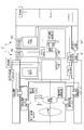
- FIG. 1 is a system configuration diagram of a camera system 3 including a lens barrel 1 and a camera body 2 according to an embodiment.
- 1 is an exploded view of a lens barrel 1.
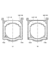
- 2A and 2B are cross-sectional views along the optical axis Z in the contracted state of the lens barrel 1, wherein FIG. 3A is an XZ cross-sectional view (cross-sectional view passing through the pitch axis P), and FIG. It is sectional drawing which passes along the axis
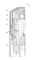
- 2A and 2B are cross-sectional views along the optical axis Z when the lens barrel 1 is expanded and contracted, where FIG. 3A is an XZ cross-sectional view (cross-sectional view passing through the pitch axis P), and FIG. It is sectional drawing which passes through Y).
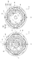
- FIG. 2 is a cross-sectional view of the lens barrel 1, wherein (a) is an XY cross-sectional view at a position passing through the pitch axis P and yaw axis Y, and (b) is an XY cross-sectional view at a position passing through the push button 70.
- FIG. 4 is a perspective view of the second housing 10 and shows a part of the pitch driving unit 20. It is a perspective view of the 2nd case 10, and shows a part of pitch drive part 20 and a yaw drive part 60.
- FIG. FIG. 4 is a perspective view of the first housing 30 and shows a part of the yaw drive unit 60.
- FIG. 4A and 4B are enlarged views of the yaw driving unit 60, in which FIG. 5A shows a state in which the distance between the subject side yaw driving coil 61A and the body side yaw driving coil 61B is extended in the yaw driving unit 60; FIG. The distance between 61A and the body side yaw drive coil 61B is reduced. It is the exploded view which looked at the yaw drive part 60 from the outside diagonal direction. It is the exploded view which looked at the yaw drive part 60 from the inner diagonal direction.
- FIG. 5A shows a state in which the distance between the subject side yaw driving coil 61A and the body side yaw driving coil 61B is extended in the yaw driving unit 60
- FIG. 5A shows a state in which the distance between the subject side yaw driving coil 61A and the body side yaw driving coil 61B is extended in the yaw driving unit 60
- FIG. 3 is a partial cross-sectional view showing a push button 70 portion of the lens barrel 1, wherein (a) shows the lens barrel 1 in an expanded state, and (b) shows the lens barrel 1 in a contracted state.
- FIG. 6 is a view showing the positional relationship between the push button 70 and the push button guide slot 54 of the fixed cylinder 50, and (a) shows the position of the push button 70 when the slider portion 62 is extended. The figure seen from the inner side, (b) shows the position of the push button 70 when the slider part 62 extends, and the figure seen from the outer side of the fixed cylinder 50, and (c) shows the case where the slider part 62 contracts.
- FIG. 4 is a perspective view of a third housing 80.
- FIG. 3 is a perspective view of a fixed cylinder 50.
- FIG. 2 is a partial cross-sectional view of the lens barrel 1.
- FIG. 4 is a perspective view showing a first housing 30 and a spherical coil 58 provided in the fixed cylinder 50.
- FIG. It is a figure explaining the drive of a yaw direction.
- FIG. It is a figure which shows the inside of the camera body 2 of this embodiment, (a) is a side view, (b) is a front view, (c) is sectional drawing. (B) is a Z1-Z1 sectional view of (c).
- FIG. 24 is a partially exploded perspective view of FIG. 23.
- the housing 160 of the body outer shell and the first holder 112 of the body inner shell 110 are shown, (a) is a state where the body inner shell 110 and the body outer shell 150 are locked, and (b) is the body inner shell. 110 shows a state in which the lock between 110 and the body outer shell 150 is released.
- 2A and 2B are peripheral views of the lens-side mount of the lens barrel 1, wherein FIG. 3A is a view seen from the camera body 2 side, and FIG. 2B is a view seen from an oblique direction on the camera body 2 side.
- FIG. FIG. 5 is a diagram illustrating the relationship between the image sensor mounting movable block 111 and the release plate 163, where (a) is the initial position of the release plate, the image sensor mounted movable block 111 is positioned in the housing 160, and (b) is the release plate release. The position where the movable block mounted with the image sensor is released from the housing 160 at the position is shown.
- an XYZ rectangular coordinate system is provided as appropriate for easy explanation and understanding.
- the photographer takes a position at the position of the camera body 2 (hereinafter referred to as a normal position) when the photographer takes a horizontal image with the optical axis horizontal.
- the direction toward the right side when viewed from the side is the X plus direction.
- the direction toward the upper side in the normal position is defined as the Y plus direction.
- the direction toward the subject at the normal position is the Z plus direction (optical axis direction).
- the terms “pitch axis P” and “yaw axis Y” are used as necessary.
- the pitch axis P is in the same direction as the X axis
- the yaw axis Y is in the same direction as the Y axis, and they are orthogonal to each other.
- “orthogonal” includes not only strictly 90 degrees but also a range slightly deviated from 90 degrees due to manufacturing errors and assembly errors.
- the rotation about the pitch axis P is pitched
- the rotation about the yaw axis Y is yawing
- the pitching direction is the pitch direction
- the yawing direction is the yaw direction.
- FIG. 1 is a system configuration diagram of a camera system 3 including a lens barrel 1 and a camera body 2 according to the embodiment.
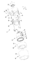
- FIG. 2 is an exploded view of the lens barrel 1.
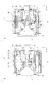
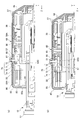
- 3A and 3B are cross-sectional views along the optical axis Z in the contracted state of the lens barrel 1, wherein FIG. 3A is an XZ cross-sectional view (cross-sectional view passing through the pitch axis P), and FIG. 3B is a YZ cross-sectional view. It is a figure (sectional drawing which passes along the yaw axis Y).
- 4A and 4B are cross-sectional views along the optical axis Z when the lens barrel 1 is expanded and contracted.
- FIG. 1 is a system configuration diagram of a camera system 3 including a lens barrel 1 and a camera body 2 according to the embodiment.
- FIG. 2 is an exploded view of the lens barrel 1.
- 3A and 3B are cross-sectional views along the optical axis Z in the contracted state of the lens barrel
- FIG. 4A is an XZ cross-sectional view (cross-sectional view passing through the pitch axis P), and FIG. 4B is a YZ cross-sectional view.
- 2 is a cross-sectional view through the yaw axis Y).
- 5A is a cross-sectional view taken along the line XY at a position passing through the pitch axis P and the yaw axis Y
- FIG. 5B is a cross-sectional view taken at a position passing through a presser slider pin 62E described later. It is Y sectional drawing.
- the lens barrel 1 of this embodiment is detachable from the camera body 2.
- the lens barrel 1 can be expanded and contracted between a contracted state (non-photographed state, a retracted state, a retracted state) and an extendable state (photographed state).
- the lens barrel 1 includes a second housing 10 (lens inner shell) that holds a lens group L that is an imaging optical system inside, and an outer periphery of the second housing 10.
- the first housing 30 is disposed, and a fixed cylinder 50 (lens outer shell) disposed on the outer periphery of the first housing 30.
- the second housing 10 and the first housing 30 are collectively referred to as a support portion 40.
- the second housing 10 can rotate in the pitch direction about the pitch axis P with respect to the first housing 30, and the first housing 30 is relative to the fixed tube 50. Thus, it can rotate in the yaw direction about the yaw axis Y.
- the lens barrel 1 further includes a third casing 80 that covers the tip of the second casing 10 and an exterior cylinder 85 that covers the entire outer periphery of the lens barrel 1 as shown in FIG.
- each casing is preferably cylindrical.
- a flat portion may be provided on the inner peripheral surface or the outer peripheral surface for arranging other components.
- the cylindrical shape of each housing may be appropriately deformed by forming a flat portion, a notch, a portion whose thickness changes, or the like.
- the second housing 10 of the lens barrel 1 includes a lens group L, a shift direction image stabilization system 4, a first motion detection unit 5, a second motion detection unit 6, and image stabilization optics.
- a system position detection unit 7, a lens control unit 8, and a lens side inner mount 9 are provided.
- the second housing 10 includes a part of the pitch driving unit 20 that drives the second housing 10 in the pitch direction with respect to the first housing 30. It is preferable that the first blur detection unit 5 is disposed on the pitch axis P.
- the lens group L includes an image stabilization optical system LB, and is an image forming optical system that forms an object image on the image sensor 101 disposed in the camera body 2.
- the first blur detection unit 5 is a gyro sensor or the like, and detects pitching and yawing of the camera system 3.
- the second blur detection unit 6 is a gyro sensor or the like, and detects shake in the shift direction, which is movement of the camera system 3 in the X-axis direction and the Y-axis direction.
- the image stabilization optical system LB that moves in the XY direction (shift direction)
- the movable frame 41 that holds the image stabilization optical system LB
- the image stabilization optical system LB A vibration-proof optical system position detector 7 for detecting the position of the moving frame 41 and a shift direction driving voice coil motor (shift direction driving VCM 42) for driving the movable frame 41 in the shift direction.
- VCM shift direction driving voice coil motor
- the lens control unit 8 controls the shift direction drive VCM 42 based on the signal input from the second blur detection unit 6.
- the image stabilization optical system LB is driven by the shift direction drive VCM 42 in a direction that cancels image blur of the subject image caused by camera shake of the photographer, and the image blur in the shift direction is corrected.
- the lens side inner mount 9 is provided on the body side end of the second housing 10 and includes a mechanical mount 91, a communication contact 92, and a power receiving contact 93.
- the second housing 10 includes a part of the pitch driving unit 20 that drives in the pitch direction.
- FIG. 6 is a perspective view of the second housing 10 and shows a part of the pitch driving unit 20.
- FIG. 7 is a perspective view of the second housing 10 and shows a part of the pitch drive unit 20 and the yaw drive unit 60.
- pitch driving unit 20 A pitch driving unit 20 that drives the second housing 10 in the pitch direction is provided on the outer periphery of the second housing 10. As shown in FIG. 6, the pitch driving unit 20 includes a pitch driving coil holding unit 21 fixed to the second housing 10, and two pitch driving coils 22 ⁇ / b> A and 22 ⁇ / b> B attached to the pitch driving coil holding unit 21. Is provided.
- the pitch driving magnet and the yoke 23A on the optical axis direction subject side the pitch driving magnet on the optical axis direction body side, and the pitch driving magnet attached to the first housing 30 (not shown in FIG. 7) and And a yoke 23B.
- the attachment state of the pitch drive magnet and the yokes 23A and 23B to the first housing 30 is shown in FIG.
- the pitch drive coils 22A and 22B have an elliptical ring shape, and are attached to the subject side and the body side of the pitch drive coil holding portion 21 so that the long axis is along the optical axis Z direction.
- a pitch bearing 25 (FIG. 6) into which a pitch shaft member 24 (FIG. 7) is rotatably inserted is provided at the center of the pitch drive coil holding portion 21.
- Ball receiving metal plates 26 are provided between the pitch bearing 25 and the pitch driving coil 22A on the subject side and between the pitch bearing 25 and the pitch driving coil 22B on the body side in the pitch driving coil holding unit 21, respectively. Yes.
- a ball 27 shown in FIGS. 3A and 4A is disposed on the ball receiving metal plate 26.
- the pitch shaft member 24 penetrates the first housing bearing 37 of the first housing 30 and is inserted into the pitch bearing 25 of the second housing 10 from the outside of the first housing 30. .
- a force is applied to the pitch drive coils 22A and 22B in the direction of the arrow in FIG. 7, and the second housing 10 rotates about the pitch axis P. To do.
- the lens barrel 1 includes a pitch direction rotation detection unit 29 that detects rotation in the pitch direction in the first housing 30, and the first housing 30 with respect to the fixed tube 50 in the yaw direction. And a part of the yaw drive unit 60 to be
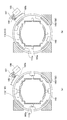
- FIG. 8 is a perspective view of the first housing 30 and shows a part of the yaw driving unit 60.
- 9A and 9B are enlarged views of the yaw driving unit 60.
- FIG. 9A is a state in which the distance between the subject side yaw driving coil 61A and the body side yaw driving coil 61B is extended in the yaw driving unit 60, and FIG. The distance between the side yaw drive coil 61A and the body side yaw drive coil 61B is reduced.
- FIG. 10 is an exploded view of the yaw drive unit 60 as seen from the outer diagonal direction.
- FIG. 11 is an exploded view of the yaw drive unit 60 as viewed from the inside oblique direction.
- the first housing 30 has a substantially octagonal shape, but a pair of two surfaces facing each other through which the pitch axis P passes are not flat but curved.
- the pitch drive magnet and the yokes 23A and 23B shown in FIGS. 7 and 8 are attached to the inside of the curved surface.
- the yaw drive unit 60 includes a subject side yaw drive coil 61A located on the subject side, a slider 62 holding the subject side yaw drive coil 61A, a body side yaw drive coil 61B located on the body side, and a body side yaw drive. And a yaw drive coil holding part 63 that holds the coil 61B.
- the yaw drive coil holding part 63 includes a coil attachment part 63A to which the body side yaw drive coil 61B is attached, and a fixing part that extends from the coil attachment part 63A to the subject side and is fixed to the first housing 30. 63B.
- the fixing portion 63B is substantially rectangular and is arranged so that the longitudinal direction thereof follows the optical axis Z.
- the fixing portion 63B has two side surfaces 63C along the optical axis Z.
- the slider part 62 is U-shaped (U-shaped).
- the inner periphery of the U-shaped portion of the slider portion 62 has two slide side surfaces 62F that are parallel to each other and extend along the optical axis Z direction.
- the distance between the two slide side surfaces 62F is substantially the same as the distance between the side surfaces 63C of the yaw drive coil holding portion 63 (the width in the direction orthogonal to the optical axis Z direction of the fixing portion 63B of the yaw drive coil holding portion 63).
- a subject side yaw drive coil 61 ⁇ / b> A is attached to the subject side of the slider unit 62.
- the slider part 62 is arranged so that the U-shaped opening side is the body side and the long side is along the optical axis Z direction.
- the slider part 62 is disposed so as to sandwich the fixing part 63B of the yaw drive coil holding part 63 between the U-shaped parts.
- the side surface 63C of the yaw drive coil holding portion 63 and the slide side surface 62F of the slider portion 62 are in contact with each other, and the slide side surface 62F can slide along the side surface 63C of the fixed portion 63B.
- the outer periphery of the U-shaped portion of the slider portion 62 has two outer surfaces 62B that are parallel to each other and extend in the optical axis Z direction. Each of the two outer surfaces 62B is provided with a claw engaging recess 62C. A push button engaging recess 62 ⁇ / b> D into which a distal end of a push button 70 described later is inserted is provided at the base portion of the U-shaped portion of the slider portion 62. Further, four slider pins 62E are provided on the inner end side of the slider portion 62 on the front end and the base portion on the camera body 2 side.
- a guide elongated hole 31 into which the four slider pins 62E are inserted is provided on the peripheral surface of the first housing 30.
- Four guide long holes 31 are provided corresponding to the positions of the slider pins 62E. Two of them are provided on both sides of the yaw drive coil holding portion 63 in the circumferential direction.
- the other two guide elongated holes 31 are provided so as to extend in the optical axis Z direction at positions spaced apart from each other by a certain distance in the optical axis Z direction.
- the four slider pins 62 ⁇ / b> E are inserted into the guide slot 31 and move along the guide slot 31. Thereby, the slider 62 is guided to move in the optical axis Z direction with respect to the first housing 30.
- a pressing plate 64 is disposed outside the slider portion 62. Three holes are formed along the optical axis Z in the center of the pressing plate 64.
- the holes of the pressing plate 64 are a hole 64A at the center of the pressing plate 64 and two holes 64B provided at both ends of the hole 64A.
- the yaw shaft member 66 passes through the bearing 50A attached to the fixed cylinder 50, the hole 64A of the holding plate 64 and the U-shaped opening of the slider 62 as shown in FIG. It is inserted into the provided yaw bearing 63E. Screws 65 are inserted into the holes 64B at both ends. The screw 65 is inserted into a screw hole 65F provided in the yaw drive coil holding portion 63 and screwed.
- the yaw driving unit 60 attached to the first housing 30 moves between the state shown in FIG. 9A and the state shown in FIG. 9B.
- the state of FIG. 9A is a state in which the slider portion 62 extends in the optical axis Z direction with respect to the yaw drive coil holding portion 63. At this time, the distance between the subject side yaw drive coil 61A and the body side yaw drive coil 61B is the longest.
- the state in FIG. 9B is a state in which the distance between the subject side yaw drive coil 61A and the body side yaw drive coil 61B is reduced. At this time, the distance between the subject side yaw drive coil 61A and the body side yaw drive coil 61B is the shortest.
- a snap fit structure is provided in order to restrict the movement range of the slider 62 in the optical axis Z direction to a certain range between FIGS. 9A and 9B.
- the snap fit structure has two claw portion engaging recesses 62C provided on the two outer side surfaces 62B of the slider portion 62 described above, and a convex claw portion 33b that engages with the claw portion engaging recesses 62C. Provided with four leaf spring portions 33 (33A, 33B).
- the leaf spring portion 33 is made of, for example, a metal member having elasticity. As shown in FIG. 10, the leaf spring part 33 includes an extending part 33a extending along the optical axis Z, a claw part 33b, and a first housing attachment part 33c.
- the first housing attachment portion 33c is provided at the proximal end of the extending portion 33a, is parallel to the circumferential surface of the first housing 30, and is fixed to the circumferential surface with screws 34.
- the extending portion 33a is bent perpendicularly to the first housing mounting portion 33c, and extends in the longitudinal direction along the optical axis Z in a state where the extending portion 33a is erected with respect to the circumferential surface of the first housing 30. Yes.
- the claw portion 33b is provided at the tip of the extending portion 33a.
- leaf springs 33 on the subject side there are two leaf springs 33 on the subject side (subject side leaf spring portion 33A) and two on the body side, adjacent to the circumferential direction of the guide elongated hole 31 so as to sandwich the yaw drive coil holding portion 63 and the slider portion 62.
- Two (body side leaf spring portions 33B) are arranged.
- the subject side leaf spring portion 33A is attached to the subject side of the first housing 30 such that the first housing attachment portion 33c is on the subject side, the claw portion 33b is on the body side, and the claw portions 33b face each other.
- the body side leaf spring portion 33B is attached to the body side of the first housing 30 so that the first housing attachment portion 33c is on the body side, the claw portion 33b is on the subject side, and the claw portions 33b face each other.
- the claw portion 33 b engages with a claw portion engaging recess 62 ⁇ / b> C provided on the side portion of the slider portion 62.
- the claw portion 33b of the subject side leaf spring portion 33A engages with the claw portion engaging recess 62C at the position where the slider portion 62 shown in FIG. 9B, the claw portion 33b of the body side leaf spring portion 33B engages with the claw portion engaging recess 62C.
- the lens barrel 1 is provided with a push button 70 for sliding the slider portion 62.
- the outer cylinder 85 and the third casing 80 are provided with holes 86 and 81 for the push button 70, respectively.
- the fixed tube 50 is provided with a push button guide slot 54.
- FIG. 12A and 12B are partial cross-sectional views showing the push button 70 portion of the lens barrel 1.
- FIG. 12A shows a state where the lens barrel 1 is extended and the slider portion 62 is extended.
- FIG. 12B shows a state where the lens barrel 1 is extended. The cylinder is contracted and the slider 62 is contracted.
- FIG. 13 is a view showing the positional relationship between the push button 70 and the push button guide slot 54 of the fixed cylinder 50.
- FIG. 13A shows the position of the push button 70 when the slider portion 62 is extended.
- FIG. 14 is a perspective view of the third housing 80.
- FIG. 15 is a perspective view of the fixed cylinder 50.
- the push button 70 includes a shaft portion 71, a pressing portion 72 that covers one end of the shaft portion 71 (the radially outer side of the lens barrel 1), and the shaft portion 71.
- a spring portion 73 attached to one end side and inside the pressing portion 72 and an engaging portion 74 provided on the other end of the shaft portion 71 (inside in the radial direction of the lens barrel 1).
- the shaft portion 71 of the push button 70 passes through the hole 86 of the outer cylinder 85, the hole 81 of the third casing 80, and the push button guide long hole 54 of the fixed cylinder 50.
- the engaging portion 74 provided at the other end of the shaft portion 71 can be inserted into the push button engaging recess 62 ⁇ / b> D of the slider portion 62 attached to the first housing 30.
- the spring portion 73 contracts and the shaft portion 71 is lowered (moves radially inward). Then, the engaging portion 74 is inserted into the push button engaging recess 62 ⁇ / b> D of the slider portion 62.
- the lens barrel 1 is extended. Then, the push button 70 is pushed, and the engaging portion 74 of the push button 70 is inserted into the push button engaging recess 62 ⁇ / b> D of the slider portion 62.
- the outer tube 85, the third casing 80, and the slider portion 62 are moved along the guide long hole 31 of the first casing 30 in the optical axis Z direction subject 2 side. Move to.
- the claw portion 33b of the body side leaf spring portion 33B rides on the claw portion engaging recess 62C, and the slide side surface 62F of the slider portion 62 slides along the side surface 63C of the fixed portion 63B.
- the subject side yaw drive coil 61A also moves to the subject side, so the distance between the subject side yaw drive coil 61A and the body side yaw drive coil 61B becomes longer.
- the claw portion engaging recess 62C comes to the position of the claw portion 33b of the subject side leaf spring portion 33A, the claw portion 33b engages with the claw portion engaging recess 62C.
- the push button 70 When the push button 70 is released, the push button 70 is raised by the urging force of the spring portion 73.
- the engaging portion 74 of the push button 70 is disengaged from the push button engaging recess 62D of the slider portion 62, but the claw portion 33b is engaged with the claw portion engaging recess 62C. Fixed.
- the claw portion 33b of the subject side leaf spring portion 33A is disengaged from the claw portion engaging recess 62C, and the slide side surface 62F of the slider portion 62 slides along the side surface 63C of the fixed portion 63B.
- the subject side yaw drive coil 61A also moves to the body side, so the distance between the subject side yaw drive coil 61A and the body side yaw drive coil 61B becomes shorter.
- the claw portion engaging recess 62C comes to the position of the claw portion 33b of the body side leaf spring portion 33B, the claw portion 33b engages with the claw portion engaging recess 62C.
- the engaging portion 74 of the push button 70 is disengaged from the push button engaging recess 62 ⁇ / b> D of the slider portion 62.
- the push button 70 is disengaged from the hole, but the claw portion 33b is engaged with the claw portion engaging recess 62C, so that the slider portion 62 is fixed.
- the slider portion 62 is contracted, the distance between the subject side yaw drive coil 61A and the body side yaw drive coil 61B is shortened, and the lens barrel 1 can be brought into a contracted state.
- the third housing 80 has a cylindrical shape in which a disk member 83 having an opening through which the second housing 10 can be inserted is integrally formed on the subject side.
- a first casing driving subject side magnet and a yoke 82 are attached to the subject side of the inner periphery of the third casing 80.
- the lens barrel 1 includes a yaw direction rotation detection unit 61 that detects rotation in the yaw direction, a third blur detection unit 53, and an operation member 59.
- the third blur detection unit 53 is a gyro sensor or the like, and detects pitching and yawing of the camera system 3.
- the third blur detection unit 53 is preferably arranged on the yaw axis Y.
- the fixed cylinder 50 includes a cylindrical portion and a disk member 56 that is integrally formed with the cylindrical portion and to which the lens side outer mount 55 is attached.
- a first housing driving body magnet and a yoke 57 are attached to the inner peripheral body side of the fixed cylinder 50.
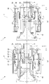
- FIG. 16 is a partial cross-sectional view of the lens barrel 1.
- FIG. 17 is a perspective view showing the first housing 30 and the spherical coil 58 provided in the fixed cylinder 50. As shown in FIG. 8 described above, the first housing 30 has a substantially octagonal shape, but a pair of two faces through which the pitch axis P passes are not flat but curved.
- a first housing bearing 37 through which the pitch shaft member 24 is inserted is provided on the curved surface.
- a spherical magnet 38 is attached to the outside of the pitch shaft member 24 in a state where the pitch shaft member 24 is inserted into the first housing bearing 37.
- a spherical coil 58 is attached to the inner surface of the fixed cylinder 50 at a position facing the spherical magnet 38.
- the position at which the spherical coil 58 and the spherical magnet 38 are attached is a position of approximately 90 degrees with respect to the position at which the yaw driving unit 60 is mounted, that is, a position approximately in the middle of the two yaw driving units 60.
- a spherical coil 58 and a spherical magnet 38 are provided.
- the spherical coil 58 and the spherical magnet 38 constitute a yaw assist driving unit 90 that assists the yaw driving unit 60.
- the spherical coil 58 and the spherical magnet 38 are preferably spherical surfaces having a radius centered in the vicinity of the intersection of the pitch axis P and the yaw axis Y in terms of driving efficiency, but are not limited thereto.
- the spherical coil 58 and the spherical magnet 38 are used, but they may be curved surfaces that are not spherical but curved only in the circumferential direction about the optical axis Z.
- FIG. 18 is a diagram for explaining the operations of the yaw driving unit 60 and the yaw auxiliary driving unit 90.
- the yaw driving unit 60 includes the first housing driving subject side magnet and yoke 82, the subject side yaw driving coil 61A, the first housing driving body side magnet and yoke 57, and the body side yaw driving coil 61B. And comprising.
- the yaw auxiliary driving unit 90 includes the spherical magnet 38 and the spherical coil 58 as described above.
- the distance between the subject side yaw drive coil 61A and the body side yaw drive coil 61B is the slider. It is longer than the case where the part 62 is contracted.
- the slider portion 62 extends in this way, the rotational moment about the yaw shaft member 66 increases, so that the drive of the first housing 30 and the second housing 10 in the yaw direction with respect to the fixed cylinder 50 is the same, for example. Even power supply can be performed with greater force.
- the spherical coil 58 and the magnet 38 are arranged in the movement between the fixed cylinder 50 and the second casing 10, but the present invention is not limited to this, and the second casing 10 and the first casing 30 are not limited thereto.
- a spherical coil and a magnet may be arranged.
- an annular elastic member 89 is attached to the inner diameter side of the disc member 83 provided at the subject-side tip of the third housing 80.
- the elastic member 89 has an outer diameter side fixed to the disk member 83 and an inner diameter side extending further to the inner diameter side than the opening 83 a of the disk member 83. The end of the portion extending to the inner diameter side is in contact with the outer peripheral surface of the second housing 10.
- a filter frame 17 is attached to the tip of the second housing 10.
- the filter frame 17 has a larger diameter than the second housing 10, and the filter frame 17 protrudes from the side surface of the second housing 10.
- the protruding portion presses the subject side of the portion extending to the inner diameter side of the elastic member 89 when the lens barrel 1 is in the contracted state.
- the lens barrel 1 side is temporarily fixed by the elastic member 89, and the image sensor 101 is attached to the camera body 2 side by a stepping motor or the like.
- the book can be fixed with.
- FIG. 19 is a view showing a modification in which the support portion 40 (second housing 10) is completely fixed to the fixed barrel 50 on the lens barrel 1 side.
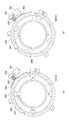
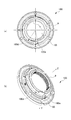
- 20A and 20B are diagrams illustrating a locked state of the support portion 40 (second housing 10) with respect to the fixed cylinder 50.
- FIG. 20A shows a locked state
- FIG. 20B shows a locked state
- a DC motor 201 and a worm gear 202 are attached to the fixed barrel 50 of the lens barrel 1.
- a lock ring 203 is rotatably attached around a cylindrical portion 94 where the lens side inner mount 9 of the second housing 10 is provided.
- a gear portion 204 is formed around the lock ring 203, and a gear member 205 is disposed between the worm gear 202 and the gear portion 204.
- the DC motor 201 is driven to rotate the worm gear 202 and the lock ring 203 is rotated via the gear member 205 and the gear portion 204. Then, the protrusion 206 provided on the inner peripheral side of the lock ring 203 comes into contact with and presses the protrusion 207 provided on the outer peripheral side of the cylindrical portion 94 of the lens side inner mount 9 of the second housing 10. . Thereby, the support part 40 (2nd housing
- the DC motor 201 When releasing the lock, the DC motor 201 is driven in the reverse direction to rotate the worm gear 202, and the lock ring 203 is rotated in the reverse direction via the gear member 205 and the gear portion 204. Then, the protrusion 206 provided on the inner peripheral side of the lock ring 203 and the protrusion 207 provided on the outer peripheral side of the cylindrical portion 94 of the lens-side inner mount 9 of the second housing 10 are in a non-contact state. The fixing of the support portion 40 (second housing 10) is released.
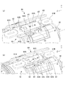
- FIGS. 21A and 21B are diagrams illustrating the arrangement of flexible printed circuit boards (FPCs) connected to the pitch driving unit 20, the yaw driving unit 60, and the yaw auxiliary driving unit 90.
- FIG. 21A is diagrams illustrating the arrangement of flexible printed circuit boards (FPCs) connected to the pitch driving unit 20, the yaw driving unit 60, and the yaw auxiliary driving unit 90.
- the FPC 600 connected to the yaw driving unit 60 includes an optical axis direction extending portion 60A and a circumferential direction bending portion 60B.
- the optical axis direction extending portion 60A extends from the lens side inner mount 9 to the subject side.
- the circumferentially curved portion 60B is connected to the subject side end of the optical axis extending portion 60A.
- the circumferentially curved portion 60B extends once in the circumferential direction to the opposite side of the yaw drive unit 60, then curves (turns in a loop) at R1.0 or more, and changes direction, and extends in the direction of the yaw drive unit 60. ing.
- the FPC 201 connected to the pitch driving unit 20 includes an optical axis direction extending portion 20A, a circumferential direction bending portion 20B, an optical axis direction extending portion 20C, and a connecting portion 20D.
- the optical axis direction extending portion 20A extends from the lens side inner mount 9 to the subject side.
- the circumferential bending portion 20B is connected to the axial subject side end of the optical axis extending portion 20A. Then, the circumferentially curved portion 20B extends in the circumferential direction on the opposite side of the pitch driving unit 20, and then bends at R1.0 or more (becomes a loop) to change direction and extend in the pitch driving unit 20 direction.
- the optical axis extending portion 20C is connected to the circumferentially curved portion 20B, and extends in a position parallel to the optical axis extending portion 20A and closer to the pitch driving unit 20 than the optical axis extending portion 20A.
- the connecting portion 20D extends from the optical axis direction extending portion 20C to the pitch driving portion 20.
- the FPC connected to the yaw auxiliary drive unit 90 includes an optical axis direction extending portion 90A extending from the lens side inner mount 9 to the subject side.
- FPC600 in radial direction cross section (XY plane), FPC600 is provided with the circumferential direction curved part 60B which has slack in the circumferential direction. Further, the slack in the circumferential direction has a margin for allowing movement in the optical axis Z direction. For this reason, when the 2nd housing
- the FPC 201 since the FPC 201 includes the circumferentially curved portion 20 ⁇ / b> B having a slack in the circumferential direction, the movement of the second casing 10 is hindered when the second casing 10 moves in the pitch direction with respect to the fixed cylinder 50 and the first casing 30. In addition, there is no problem that the FPC breaks due to excessive force applied to the FPC.
- the first housing has a substantially octagonal plane that is substantially orthogonal to the diagonal line.
- the fixed cylinder 50 also has a plane substantially orthogonal to the diagonal line as shown in FIG. Since the FPCs 600 and 201 are fixed on these planes, they can be firmly fixed as compared to the case of fixing to a curved surface.
- the slack is an arrangement / orientation substantially opposite to the diagonal line.
- the slack is arranged at a plurality of diagonal portions and is opposed to the optical axis Z as a reference.
- positioning facing on the basis of the X-axis or the Y-axis may be sufficient.
- the camera body 2 includes a body inner shell 110 and a body outer shell 150 (body fixing portion).
- the body inner shell 110 includes an image sensor 101, a body shake detection unit 102, a body rotation detection unit 104, a roll direction vibration isolation system 105, a body side inner mount 109, and a body control unit 103.
- the image sensor 101 receives the light incident from the imaging optical system (lens group L) and converts it into an electrical signal.
- the body shake detection unit 102 is a gyro sensor or the like, and detects rolling of the camera system 3.
- the roll direction image stabilization system 105 corrects the blur in the roll direction of the camera system 3 by rotating the image sensor 101.
- the body rotation detection unit 104 detects the rotation of the image sensor 101.
- the body control unit 103 receives the output from the body shake detection unit 102 and the output from the body rotation detection unit 104, and calculates the drive amount of the roll direction vibration isolation system 105.
- the body side inner mount 109 is provided at the subject side end of the body inner shell 110 and includes a mechanical mount 191, a communication contact 192, and a power supply contact 193.
- the body outer shell 150 includes a body-side outer mount 151 that is a mechanical mount, a display unit 150A, a battery insertion unit 150B, and an operation member 150C.
- the body side inner mount 109 and the body side outer mount 151 are collectively referred to as a body mount 200 as appropriate.
- the camera body 2 only needs to include at least the body-side inner mount 109, the imaging element 101, and the body outer shell (body fixing portion) 150, and may not include the operation member 150C and the display portion 150A.
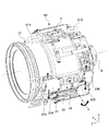
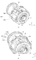
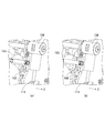
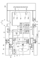
- FIG. 22A and 22B are views showing the inside of the camera body 2 of the present embodiment, where FIG. 22A is a side view, FIG. 22B is a front view, and FIG. 22C is a cross-sectional view. (B) is a Z1-Z1 sectional view of (c).
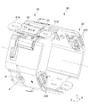
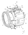
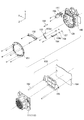
- FIG. 23 is an exploded perspective view of the inside of the camera body 2 shown in FIG.
- the body outer shell 150 of the camera body 2 includes a body-side outer mount 151, a contact block 152, a first locking lever 153, a second locking lever 154, a release plate biasing spring 155, and a locking lever bias.
- a spring 156, a mounting nut 157, a stepping motor 158, a photo reflector 159, a housing 160, and a drive nut 161 are provided.
- the body outer shell 150 of the camera body 2 further includes a guide pin 162, a release plate 163, and a fixed plate 164.
- the body inner shell 110 of the camera body 2 includes an imaging element mounting movable block 111.
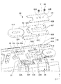
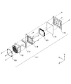
- 24 is an exploded perspective view of the image sensor mounting movable block 111 of FIG.
- the image sensor mounting movable block 111 includes a body side inner mount 109, a first holder 112, a low pass filter 113, a second holder 114, an image sensor 101, an image sensor FPC 115, and a mounting plate 116. And comprising.
- FIG. 25 shows the housing 160 of the body outer shell 150 and the first holder 112 of the body inner shell 110.
- FIG. 25A shows a state in which the body inner shell 110 and the body outer shell 150 are locked.
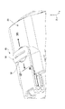
- FIG. 26A and 26B are peripheral views of the lens-side mount 100, where FIG. 26A is a view seen from the camera body 2 side, and FIG. 26B is a view seen from an oblique direction on the camera body 2 side.
- the lens side mount 100 includes a lens side inner mount 9 and a lens side outer mount 55.
- the lens-side mount 100 is provided with two locking lever drive pins 100d and 100e.
- FIG. 27 is a view showing the locking levers 153 and 154, where (a) shows a state in the housing 160, and (b) shows a state in which the housing 160 is omitted.
- the locking lever 153 can swing around the fixed shaft 153a.
- the locking lever 153 has a slide plate portion 153b on the inner peripheral side.
- the slide plate portion 153b has a portion that protrudes toward the optical axis with respect to the locking lever body 153c.
- the locking lever drive pin 100d provided on the lens side mount 100 of the lens barrel 1 moves so as to abut on the outer peripheral surface of the slide plate portion 153b which is the protruding portion.
- the slide plate portion 153b has a front portion 153ba and a rear portion 153bb in the rotation direction R (shown in FIG. 27, counterclockwise in the figure) in which the lens side mount 100 is relatively rotated when the lens side mount 100 is mounted. .
- the tip portion of the front portion 153ba is bent outward (in the direction in which the diameter from the optical axis becomes larger) than the connecting portion with the rear portion 153bb.
- an arm extending in the Z minus direction is provided at an end portion (rear side in the rotation direction R) of the rear portion 153bb of the locking lever 153, and a claw portion 153d is formed at the tip of the arm.
- the locking lever 154 can swing around the fixed shaft 154a.
- the locking lever 154 has a front portion 154ba and a rear portion 154bb in the direction R (shown in FIG. 27, counterclockwise in FIG. 27) in which the lens side mount 100 is relatively rotated when the lens side mount 100 is mounted.
- the front end portion 154ba is bent inwardly (in the direction in which the diameter from the optical axis is smaller) at the front end portion than the connecting portion with the rear portion 154bb.
- the locking lever drive pin 100e provided on the lens side mount 100 of the lens barrel 1 moves so as to contact the inner peripheral surfaces of the rear portion 154bb and the front portion 154ba.
- an arm extending in the Z minus direction is provided at the tip of the tip portion 154ba (the front side in the rotation direction R), and a claw portion 154d is formed at the tip of the arm.
- FIG. 28 is a diagram illustrating the relationship between the image sensor mounting movable block 111 and the release plate 163.
- FIG. 28A is an initial position of the release plate 163, and the image sensor mounted movable block 111 is positioned in the housing 160.
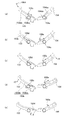
- FIG. 29 is an interlocking view of the locking levers 153 and 154 when the lens side mount 100 is coupled to the body mount 200.
- Step 1 The lens side mount 100 and the body mount 200 are not yet coupled.
- the locking lever drive pin 100d is located away from both the locking levers 153 and 154.
- the locking lever drive pin 100e is at the same position in the circumferential direction as the slide plate portion 153b of the locking lever 153, but is not in contact with it and is away from the locking lever 154.
- Step 2 This is a state rotated 35 degrees from the state of step 1.
- the locking lever driving pin 100e contacts the inner surface of the locking lever 154 and moves along the inner surface.
- the inner surface of the locking lever 154 and the contact portion of the locking lever driving pin 100e are in the optical axis Z.
- the locking lever 154 which is at the same distance from is not moved.
- the locking lever driving pin 100d is in contact with the outer surface of the slide plate portion 153b of the locking lever 153 and moves along the outer surface, but the outer surface of the slide plate portion 153b and the contact portion of the locking lever driving pin 100d Are at the same distance from the optical axis Z, the locking lever 153 does not move.
- Step 3 This is a state rotated 45 degrees from the state of step 1.
- the locking lever drive pin 100e starts contact with the inner surface of the front portion 154ba of the locking lever 154.
- the front end portion 154ba is bent inwardly (in the direction in which the diameter from the optical axis is smaller) at the front end portion than the connecting portion with the rear portion 154bb. Therefore, since the locking lever drive pin 100e moves a certain distance from the optical axis Z, the front portion 154ba of the locking lever 154 is pushed outward. As a result, the locking lever 154 rotates clockwise in the figure around the fixed shaft 154a (arrow r1).
- the claw portion 154d moves outward, and the claw portion 154d moves away from the first holder 112 as shown in FIG.
- the locking lever drive pin 100d is in contact with the outer surface of the slide plate portion 153b of the locking lever 153.
- the outer surface has a constant diameter from the optical axis Z, the locking lever 153 does not move.
- Step 4 This is a state rotated by 50 degrees from the state of step 1. Since the locking lever drive pin 100e pushes the front portion 154ba of the locking lever 154 outward, the claw portion 154d moves outward, and the claw portion 154d is moved from the first holder 112 as shown in FIG. Keep away. At this time, the locking lever drive pin 100d starts to contact the outer surface of the front portion 153ba of the slide plate portion 153b. The tip portion of the front portion 153ba is bent outward (in the direction in which the diameter from the optical axis becomes larger) than the connecting portion with the rear portion 153bb. Therefore, the locking lever drive pin 100d pushes the outer surface of the front portion 154ba of the locking lever 15 inward. As a result, the locking lever 153 rotates counterclockwise in the figure around the fixed shaft 154a (arrow r2).
- Step 5 This is a state rotated by 60 degrees from the state of step 1. Since the locking lever drive pin 100e pushes the front portion 154ba of the locking lever 154 outward, the claw portion 154d moves outward, and the claw portion 154d is moved from the first holder 112 as shown in FIG. Keep away. Since the locking lever drive pin 100d pushes the front portion 153ba of the locking lever 153 inward, the claw portion 153d moves outward, and the claw portion 153d is moved from the first holder 112 as shown in FIG. Keep away.
- the photo reflector reacts when the second pin is removed. The reaction of the photo reflector is a trigger, and the stepping motor 158 shown in FIG. 28 starts to drive, and the release plate 163 descends backward as shown in FIG. 28, and the body inner shell 110 and the body outer shell 150 are separated. .
- a lens barrel that is detachable from the image pickup unit, which is connected to the body outer shell 150 that contains the image pickup device 101, and a subject image is connected to the image pickup unit 101.
- the 101 imaging unit is fixed to the body outer shell 150 when the lens barrel 1 is not attached, but is not fixed to the body outer shell 150 when the lens barrel 1 is attached. This is a so-called detached state.
- the configuration of locking the body inner shell 110 and the body outer shell 150 is configured in both the thrust direction and the radial direction. Then, the mechanical locking between the body inner shell 110 and the body outer shell 150 is released stepwise by the existing lens mounting rotation operation.
- the body inner shell 110 is connected to the second housing 10 of the lens barrel 1, and the body outer shell 150 is connected to the fixed barrel 50 of the lens barrel 1.
- the body inner shell 110, together with the second housing 10 of the lens barrel 1, rotates and yaw around the pitch axis P of the second housing 10 with respect to the body outer shell 150 and the fixed barrel 50 of the lens barrel 1. Rotation about the axis Y is possible.
- the type of still image and blur are different.
- the blur angle is large. For this reason, enlargement of the blur correction angle that can be corrected is required.
- the image sensor mounting movable block 111 that is not locked at all is fixed from both sides at the same time, which is difficult to fix.
- the locking operation and the unlocking operation of the body inner shell 110 and the body outer shell 150 are held in stages by two or more continuous operations, so that the fixing is easy.
- the camera body 2 of the embodiment includes a body side inner mount 109 and a body side outer mount 151.
- the lens-side mount can be attached to and detached from the body-side outer mount 151. Therefore, it is possible to mount a lens barrel that does not include a lens-side inner mount.
- the example in which the body inner shell 110 and the body outer shell 150 are physically (mechanically) locked has been described.
- the claw portions 153d and 154d are provided in the body outer shell 150, but the body inner shell 110 may be provided with the claw portions 153d and 154d and locked from the body inner shell 110.
- the body outer shell 150 and the body inner shell 110 may be provided with claw portions 153d and 154d and may be locked from both sides.
- the body inner shell 110 may be locked using, for example, an electromagnetic force, without being limited to an example of physically (mechanically) locking.
- the body inner shell 110 may be held (locked) while being floated from the body outer shell 150 by electromagnetic force, or the body inner shell 110 may be attracted to a part of the body outer shell 150 by electromagnetic force. You can lock it.
- the locked state referred to here is not limited to a state in which the body inner shell 110 and the body outer shell 150 do not move relatively.
- the movable range of the body inner shell 110 may be limited to the extent that the body inner shell 110 and the body outer shell 150 do not contact each other.
- the position of the body inner shell 110 with respect to the body outer shell 150 may be limited as long as the lens barrel can be easily mounted on the camera body.
- the movable range of the body inner shell 110 relative to the body outer shell 150 can be switched between a locked state and an unlocked state. Specifically, if the movable range of the body inner shell 110 in the unlocked state is the first range, the movable range of the body inner shell 110 in the locked state is limited to a second range that is narrower than the first range. .
- the second range is a range included in the first range.
- the lock between the body inner shell 110 and the body outer shell 150 is released using a manual rotation operation by the user when the lens barrel 1 is attached to the camera body 2 as a driving source.
- the lock release may be performed when the connection between the body side inner mount 109 and the lens side inner mount 9 is electrically detected.
- an electric actuator may be used as a drive source for locking the body inner shell 110 with respect to the body outer shell 150.
- an urging force such as a spring may be used as a driving source for locking the body inner shell 110 with respect to the body outer shell 150.
- the lens barrel 1 includes the shift direction image stabilization system 4 including the image stabilization optical system LB that moves in the XY direction (shift direction) (this shift direction image stabilization system 4). (This is called lens shift blur correction.)
- a blur correction operation (herein referred to as “lens tilt blur correction”) performed by moving the image stabilization optical system LB in the tilt direction may be provided.
- the lens barrel 1 and the camera body 2 according to the present embodiment include an imaging element 101 and a lens that the body inner shell 110 of the camera body 2 has as a shake correction operation using the pitch driving unit 20 and the yaw driving unit 60.
- a blur correction operation (herein referred to as integral drive blur correction) performed by driving the lens group L of the second housing 10 of the lens barrel 1 integrally is provided.
- the body inner shell 110 and the lens inner shell are interlocked.
- the body inner shell 110 is driven in conjunction with the driving of the lens inner shell by the pitch driving unit 20 or the yaw driving unit 60 provided in the lens barrel.
- the camera body 2 of the present embodiment includes a roll direction image stabilization system 105 (herein referred to as an image sensor roll blur correction) that rotates the image sensor 101.
- a blur correction operation (herein referred to as an image sensor shift blur correction) performed by shifting the image sensor 101 may be further provided.
- a blur correction operation (herein referred to as an image sensor tilt blur correction) performed by operating the image sensor 101 in the tilt direction may be further provided.
- the example in which the lock between the body inner shell 110 and the body outer shell 150 is released in conjunction with the manual rotation operation by the user when the lens barrel 1 is attached to the camera body 2 has been described.
- the lock may be released based on the shooting mode selected by the photographer.
- the camera may determine the shooting environment (shooting conditions) at that time and automatically release the lock.
- the photographer may be able to designate the release of the lock by performing an operation input using a mode dial, a mode button, a touch panel, and other operation input members, as the content of the shake correction to be performed.
- the lock can be released and the movable range of the body inner shell 110 can be switched from the second range (narrower than the first range) to the first range.
- the integral drive blur correction may not be performed without unlocking the body inner shell 110 and the body outer shell 150. .
- lens shift blur correction, lens tilt blur correction, image sensor roll blur correction, image sensor shift blur correction, or image sensor tilt blur correction may be performed.
- lens shift blur correction is considered suitable for small blur correction. It is. Further, in the moving image shooting mode, the lock between the body inner shell 110 and the body outer shell 150 may be released, and the integral driving blur correction may be performed. At this time, the lens shift blur correction, the lens tilt blur correction, the image sensor shift blur correction, and the image sensor roll blur correction may or may not be performed. In the moving image shooting mode, there are many cases where shooting is performed while moving, and there is a high possibility that a large blur will occur. Therefore, it is conceivable to perform an integral driving blur correction capable of a greater blur correction.
- the movable range of the body inner shell 110 can be switched based on the shooting mode. Even if the lens barrel is attached to the camera body, the body inner shell 110 and the body outer shell are not used when shooting (when the power is not turned on, in the playback mode, when the lens barrel is retracted, etc.). 150 may remain locked. This is because the integral drive blur correction is not performed during non-shooting.
- the lock may be released, and the integrated drive blur correction may be performed.
- the lock when performing panning, for example, when performing panning in the horizontal direction while holding the camera in the normal position, the lock may be released.
- only one of the integrated drive blur corrections may be performed, such as driving the pitch driving unit 20 without driving the yaw driving unit 60.
- the driving of the yaw driving unit 60 and the driving of the pitch driving unit 20 may be weighted.
- the camera body 2 may automatically determine whether or not the panning is being performed and the direction of the panning or may be selectively accepted by the user. It can be automatically determined by providing various sensors such as an acceleration sensor.
- the control unit comprehensively determines using a detection value obtained from a known sensor such as an acceleration sensor, a gyro sensor, or a distance sensor included in the camera body 2 or the lens barrel 1, and executes any blur correction operation. It may be switched after judging. For example, when the sensor included in the camera body 2 or the lens barrel 1 detects a blur smaller than a predetermined value, the body inner shell 110 and the body outer shell 150 are not unlocked and the integral driving blur correction is not performed. Also good. In that case, other blur correction may be performed.
- the lock between the body inner shell 110 and the body outer shell 150 may be released, and the integral drive shake correction may be performed.
- the movable range of the body inner shell 110 can be switched based on the shooting environment (shooting conditions).
- locking and unlocking the body inner shell 110 with respect to the body outer shell 150 is not limited to the attachment / detachment of the lens barrel 1 or the various examples described above.
- a manual operation member (switch) for locking or unlocking the body inner shell 110 with respect to the body outer shell 150 is provided in the camera body 2 and the manual operation member is driven by a user's manual operation.
- the locking operation and the unlocking operation may be performed using force. That is, the user can move the manual operation member provided on the camera body 2 to perform the locking operation and the unlocking operation.
- an unlock button may be displayed on a display unit including a touch panel, and the lock may be released when it is detected that the unlock button has been touched.
- the actuator may be activated and unlocked based on the user operation as described above.
- the manual operation member (switch) may be provided on the lens barrel.
- whether to unlock the body inner shell 110 and the body outer shell 150 can be determined according to various conditions.
- the body inner shell 110 and the body outer shell 150 of the camera body 2 are locked, and when performing the integral drive shake correction, the body inner shell 110 and the body outer shell 150 are locked.
- Unlock Whether or not to unlock the body inner shell 110 and the body outer shell 150 may be determined depending on whether or not the user desires to execute the integral driving shake correction.
- the locked state and the unlocked state can be switched according to various conditions as described above.
- the body inner shell 110 and the body outer shell 150 may be locked by a lid attached to the body mount when the lens is not attached.
- lens shift blur correction, lens tilt blur correction, integral driving blur correction, image sensor roll blur correction, image sensor shift blur correction, and image sensor tilt blur correction may be combined as appropriate. That is, one type or a plurality of types may be selectively combined, or all may be driven simultaneously. Which blur correction is performed may be switched based on the shooting mode selected by the photographer. The camera may switch automatically by judging the shooting environment (shooting conditions) at that time. The photographer may be able to specify the details of the shake correction to be performed by an operation input using a mode dial, a mode button, a touch panel, and other operation input members.
- any of lens shift blur correction, lens tilt blur correction, image sensor shift blur correction, image sensor roll blur correction, or image sensor tilt blur correction is performed.
- the drive blur correction may not be performed. This is because it is considered that other blur correction is suitable for the still image shooting mode as described above.
- the integral drive blur correction may be performed and the other blur correction may not be performed. This is because, as described above, in the moving image shooting mode, it is conceivable to perform the integral driving blur correction capable of larger blur correction.
- control unit comprehensively determines using a detection value obtained from a known sensor such as an acceleration sensor, a gyro sensor, or a distance sensor included in the camera body 2 or the lens barrel 1, and executes any blur correction operation. It may be switched after judging. For example, when the sensor included in the camera body 2 or the lens barrel 1 detects a blur smaller than a predetermined value, the lens shift blur correction, the lens tilt blur correction, the image sensor shift blur correction, the image sensor roll blur correction, and the image sensor tilt blur correction are performed. May be. When the sensor detects a shake larger than a predetermined value, the integral drive shake correction may be performed.
- switching based on a set shutter speed can be considered. For example, when the shutter speed is longer than a predetermined time, switching may be performed so as to perform the integrated drive blur correction.
- the pitch driving unit 20 is driven without driving the yaw driving unit 60. For example, only one of the integral drive blur corrections may be performed.
- the driving of the yaw driving unit 60 and the driving of the pitch driving unit 20 may be weighted. Note that the camera body 2 may automatically determine whether or not the panning is being performed and the direction of the panning or may be selectively accepted by the user.
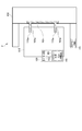
- FIG. 31 is a diagram illustrating a second embodiment of the camera body 2.
- the camera body 2 of the second embodiment has the same form as the camera body 2 of the first embodiment, except that the form of locking the first holder 112 of the body inner shell 110 is different from the first embodiment. Therefore, the same reference numerals are given to the portions that perform the same functions as those in the first embodiment described above, and repeated descriptions are omitted as appropriate.
- FIG. 31A shows a state where the body inner shell 110 and the body outer shell 150 are locked
- FIG. 31B shows that the body inner shell 110 and the body outer shell 150 are unlocked. Indicates the state.
- a DC motor 166 having a worm gear 167 as an output shaft is attached to the body outer shell 150 or a member fixed to the body outer shell 150.
- a lock ring 165 is rotatably attached to the housing 160 of the body outer shell 150.
- a gear portion 165 b is provided on a part of the outer periphery of the lock ring 165.
- a gear member 168 is disposed between the worm gear 167 and the gear portion 165b.
- the DC motor 166 When locking the body inner shell 110, the DC motor 166 is driven to rotate the worm gear 167, and the lock ring 165 is rotated via the gear member 168 and the gear portion 165b. Then, the protrusion 165a provided on the inner peripheral side of the lock ring 165 comes into contact with and presses the protrusion 112a provided on the outer peripheral side of the first holder 112 of the body inner shell 110. Thereby, the first holder 112 of the body inner shell 110 is fixed. Therefore, the body inner shell 110 and the body outer shell 150 are connected.
- the DC motor 166 When unlocking the body inner shell 110, the DC motor 166 is driven in the opposite direction to that during the locking operation, and the worm gear 167 is rotated in the opposite direction to that during the locking operation. Accordingly, the lock ring 165 is rotated in the reverse direction via the gear member 168 and the gear portion 165b. Then, the protrusion 165a provided on the inner peripheral side of the lock ring 165 and the protrusion 112a provided on the outer peripheral side of the first holder 112 of the body inner shell 110 are brought into a non-contact state, and the The fixing of one holder 112 is released. Therefore, the connection between the body inner shell 110 and the body outer shell 150 is released. Instead of the worm gear 167, a flat gear may be used.
- a known technique can be applied as long as the driving force can be secured.
- a piezoelectric element may be used for securing the driving force.
- the connecting portion referred to here may be any combination of the worm gear 167, the DC motor 166, the lock ring 165, and the gear member 168, and other configurations may be combined.
- FIG. 32 is a diagram illustrating an unlocked state of the camera body 2 according to the third embodiment.
- FIG. 33 is a diagram illustrating a locked state of the camera body 2 according to the third embodiment.
- the camera body 2 of the third embodiment has the same form as the camera body 2 of the first embodiment, except that the form for locking the body inner shell 110 is different from that of the first embodiment. Therefore, the same reference numerals are given to the portions that perform the same functions as those in the first embodiment described above, and repeated descriptions are omitted as appropriate.
- the camera body 2 includes a plurality of holes 110a in the body inner shell 110.
- the hole part 110a is shown as having a bottom in the drawing, it may be a through hole.
- the body outer shell 150 is provided with a lock member 169 having a plurality of insertion portions 169a that can be inserted into the holes 110a.
- the lock member 169 is driven by an actuator (not shown) to insert the insertion portion 169a into the hole portion 110a to lock the body inner shell 110 (FIG. 33), or to contrast the insertion portion 169a with the hole portion 110a.
- the lock can be released (FIG. 32).
- the connecting portion that connects the body inner shell 110 and the body outer shell 150
- the movable range of the body inner shell 110 is set to the first range (movable range when unlocked) and the second range (when locked).
- the range of movement) can be switched.
- the connecting portion referred to here may be a lock member 169, a combination of actuators, or any one of them, and other configurations may be combined.
- the actuator that drives the lock member 169 may be, for example, an electric actuator, or an actuator (manual operation interlocking mechanism) that operates by obtaining a driving force from a manual rotation operation when the lens barrel 1 is mounted. May be used.
- the camera body 2 of the fourth embodiment includes an elastic member between the body inner shell 110 and the body outer shell 150.
- the elastic member include elastic members such as a spring, rubber, gel, and cotton.
- the body inner shell 110 and the body outer shell 150 are connected by a spring.
- the body inner shell 110 is driven in conjunction with the driving of the lens inner shell by the pitch driving unit 20 or the yaw driving unit 60 provided in the lens barrel. That is, the body inner shell is driven by the driving force of the pitch driving unit 20 or the yaw driving unit 60.
- the integral drive blur correction is not performed, the body inner shell is supported on the body outer shell by the spring. As a result, the same effects as in the locked state and the unlocked state described in the first to third embodiments can be obtained.
- the camera body 2 is in a state in which the lock of the body inner shell 110 is released when the lens barrel 1 is mounted or when the integral drive blur correction is performed.
- the movable range of the body inner shell 110 is in the first range.
- the body inner shell 110 of the camera body 2 and the lens inner shell (second housing 10) of the lens barrel 1 are driven in conjunction with each other, and the lens and the image sensor are driven together to perform blur correction. be able to.
- By driving the lens and the image sensor together to perform blur correction it is possible to correct a larger blur than lens shift correction, image sensor shift correction, or the like.
- the camera body 2 is in a state where the body inner shell 110 is locked (the movable range of the body inner shell 110 is narrower than the first range) when the lens barrel 1 is removed or when the integral drive blur correction is not performed. Two ranges). Thereby, contact with body inner shell 110 and body outer shell 150 can be prevented. By preventing the contact between the body inner shell 110 and the body outer shell 150, it is possible to prevent a failure due to a collision between the two. Improves impact resistance. Further, the position of the body inner shell 110 can be held at a specific position with respect to the body outer shell 150. The lens barrel 1 can be easily attached to the camera body 2 by holding the position of the body inner shell 110 at a specific position with respect to the body outer shell 150. Note that the above-described detection unit that detects the blurring of the lens barrel or the camera body may be provided in any of the lens inner shell, the lens outer shell, the body inner shell 110, and the body outer shell 150.
- FIG. 30 is a system configuration diagram of a camera system 3 ′ including a modified lens barrel 1 ′ and a camera body 2 ′.
- the lens-side outer mount 9 ′ includes a communication contact 92 ′ and a power receiving contact 93 ′, the body-side outer mount 151 ′ is connected, and the communication contact 192 ′ and the power supply contact 193 ′ are connected. May be provided.
- the imaging optical system (lens group L) and the image pickup device 101 are integrally rotated about the pitch axis P and the yaw axis Y, and the image pickup optical system is further moved in the XY directions. 101 moves in the roll direction.
- a part of the imaging optical system (lens group L) and the image sensor 101 may be integrated and rotated about the pitch axis P and the yaw axis Y. Only the image sensor 101 may be rotated about the pitch axis P and the yaw axis Y.
- the lens barrel 1 may rotate about the pitch axis P and the yaw axis Y, and the image sensor 101 may move in the X direction and the Y direction.
- the lens barrel 1 may be rotated about the pitch axis P and the yaw axis Y, and the image sensor 101 may be in the X direction, the Y direction, and the roll direction.
- driving a plurality of members they may be used properly depending on coarse / fine movement, blur frequency, and the like. Low frequency may be removed by a high-power actuator on the outside, and high frequency may be moved by a light actuator on the inside.
- the lens barrel 1 includes a pitch driving unit 20 that drives the second housing 10 in the pitch direction, and a yaw driving unit 60 that drives the first housing 30 and the second housing 10 in the yaw direction.
- the configuration has been described.
- the lens barrel 1 has a pitch driving unit 20 that drives the second housing 10 in the pitch direction, and a yaw driving unit that drives the first housing 30 and the second housing 10 in the yaw direction.
- the structure provided with 60 was demonstrated, not only this but these drive parts may be provided in the camera body 2 side.
- the camera body 2 has been described with an example in which a mechanism for locking the body inner shell 110 with respect to the body outer shell 150 is provided.
- the camera body 2 may be configured not to include a mechanism for locking the body inner shell 110 with respect to the body outer shell 150.
- the lid member (body cap) that is attached to the camera body 2 that does not include the lock mechanism and closes the mount opening portion holds the body inner shell 110 at a predetermined position. May be provided.
- the lens inner shell and the lens outer shell may be locked with a lens cap.
Landscapes
- Physics & Mathematics (AREA)
- General Physics & Mathematics (AREA)
- Optics & Photonics (AREA)
- Engineering & Computer Science (AREA)
- Multimedia (AREA)
- Signal Processing (AREA)
- General Engineering & Computer Science (AREA)
- Adjustment Of Camera Lenses (AREA)
- Studio Devices (AREA)
- Lens Barrels (AREA)
- Structure And Mechanism Of Cameras (AREA)
- Accessories Of Cameras (AREA)
Priority Applications (4)
| Application Number | Priority Date | Filing Date | Title |
|---|---|---|---|
| US15/769,081 US10795117B2 (en) | 2015-10-22 | 2016-10-24 | Lens barrel and camera body |
| CN202011277211.1A CN112327560B (zh) | 2015-10-22 | 2016-10-24 | 镜头镜筒和相机机身 |
| CN201680075144.0A CN108431688B (zh) | 2015-10-22 | 2016-10-24 | 镜头镜筒和相机机身 |
| US17/019,556 US11733478B2 (en) | 2015-10-22 | 2020-09-14 | Lens barrel and camera body |
Applications Claiming Priority (2)
| Application Number | Priority Date | Filing Date | Title |
|---|---|---|---|
| JP2015207790A JP6672696B2 (ja) | 2015-10-22 | 2015-10-22 | レンズ鏡筒及びカメラボディ |
| JP2015-207790 | 2015-10-22 |
Related Child Applications (2)
| Application Number | Title | Priority Date | Filing Date |
|---|---|---|---|
| US15/769,081 A-371-Of-International US10795117B2 (en) | 2015-10-22 | 2016-10-24 | Lens barrel and camera body |
| US17/019,556 Continuation US11733478B2 (en) | 2015-10-22 | 2020-09-14 | Lens barrel and camera body |
Publications (1)
| Publication Number | Publication Date |
|---|---|
| WO2017069283A1 true WO2017069283A1 (ja) | 2017-04-27 |
Family
ID=58557597
Family Applications (1)
| Application Number | Title | Priority Date | Filing Date |
|---|---|---|---|
| PCT/JP2016/081411 Ceased WO2017069283A1 (ja) | 2015-10-22 | 2016-10-24 | レンズ鏡筒及びカメラボディ |
Country Status (4)
| Country | Link |
|---|---|
| US (2) | US10795117B2 (enExample) |
| JP (1) | JP6672696B2 (enExample) |
| CN (2) | CN108431688B (enExample) |
| WO (1) | WO2017069283A1 (enExample) |
Cited By (4)
| Publication number | Priority date | Publication date | Assignee | Title |
|---|---|---|---|---|
| WO2018198258A1 (ja) * | 2017-04-26 | 2018-11-01 | 株式会社ニコン | レンズ鏡筒、カメラボディ、カメラシステム |
| WO2018198259A1 (ja) * | 2017-04-26 | 2018-11-01 | 株式会社ニコン | レンズ鏡筒、カメラボディ、カメラシステム |
| EP3575857A1 (en) * | 2018-06-01 | 2019-12-04 | Ridha Ben-Mrad | An autofocus and optical image stabilizer system |
| CN110737158A (zh) * | 2018-07-20 | 2020-01-31 | 卡尔蔡司股份公司 | 物镜的物镜基体、物镜的外壳体、物镜系统和物镜组件 |
Families Citing this family (13)
| Publication number | Priority date | Publication date | Assignee | Title |
|---|---|---|---|---|
| JP6811589B2 (ja) * | 2016-11-10 | 2021-01-13 | 日本電産サンキョー株式会社 | 振れ補正機能付き光学ユニット |
| JP6800707B2 (ja) * | 2016-11-10 | 2020-12-16 | 日本電産サンキョー株式会社 | 振れ補正機能付き光学ユニット |
| WO2018186176A1 (ja) * | 2017-04-03 | 2018-10-11 | 富士フイルム株式会社 | 撮像装置、撮像用制御方法、及びプログラム |
| JP7014224B2 (ja) * | 2017-04-26 | 2022-02-01 | 株式会社ニコン | レンズ鏡筒、カメラボディ、カメラシステム |
| CN113439225B (zh) * | 2019-02-21 | 2024-03-08 | 株式会社尼康 | 透镜镜筒以及摄像装置 |
| CN112333351B (zh) * | 2019-08-05 | 2022-04-05 | 华为技术有限公司 | 一种摄像模组及移动终端 |
| US11409069B2 (en) * | 2019-11-15 | 2022-08-09 | Tdk Taiwan Corp. | Optical element driving mechanism |
| TWI731724B (zh) * | 2020-06-20 | 2021-06-21 | 大陽科技股份有限公司 | 攝影鏡頭、鏡頭驅動模組與電子裝置 |
| WO2022097506A1 (ja) * | 2020-11-05 | 2022-05-12 | ソニーグループ株式会社 | レンズ鏡筒、制御方法、撮像装置 |
| CN114827437B (zh) * | 2021-01-28 | 2023-07-18 | 华为技术有限公司 | 一种云台模组、摄像头模组和电子设备 |
| WO2022239643A1 (ja) * | 2021-05-12 | 2022-11-17 | 株式会社ニコン | ブレ補正装置、レンズ鏡筒、及び撮像装置 |
| JP7273127B1 (ja) | 2021-11-15 | 2023-05-12 | 旭化成エレクトロニクス株式会社 | カメラモジュール、ポータブル電子機器、および、位置制御システム |
| US12401901B2 (en) * | 2022-01-20 | 2025-08-26 | Asahi Kasei Microdevices Corporation | Driving apparatus and driving method for driving lens with corrected tilt |
Citations (5)
| Publication number | Priority date | Publication date | Assignee | Title |
|---|---|---|---|---|
| JP2011048186A (ja) * | 2009-08-27 | 2011-03-10 | Nikon Corp | ブレ補正装置およびブレ補正装置を備えた光学機器 |
| JP2013174639A (ja) * | 2012-02-23 | 2013-09-05 | Tamron Co Ltd | レンズユニット |
| WO2015093083A1 (ja) * | 2013-12-17 | 2015-06-25 | オリンパス株式会社 | 撮像装置及び撮像装置の制御方法 |
| JP2015121755A (ja) * | 2013-12-25 | 2015-07-02 | キヤノン株式会社 | 像振れ補正装置、レンズ装置、および、撮像装置 |
| JP2015179231A (ja) * | 2014-03-20 | 2015-10-08 | Hoya株式会社 | 撮像装置 |
Family Cites Families (19)
| Publication number | Priority date | Publication date | Assignee | Title |
|---|---|---|---|---|
| JPH09243965A (ja) * | 1996-03-07 | 1997-09-19 | Sony Corp | 手振れ補正装置の取付け構造 |
| JPH10293334A (ja) | 1997-04-17 | 1998-11-04 | Canon Inc | 位置制御装置及び補正光学装置 |
| US5926322A (en) * | 1997-08-04 | 1999-07-20 | Fuji Photo Film Co., Ltd. | Zoom lens device with zooming position detector |
| JP2001296574A (ja) | 2000-04-14 | 2001-10-26 | Olympus Optical Co Ltd | 防振カメラ |
| US20090269046A1 (en) * | 2005-09-16 | 2009-10-29 | Satoshi Yamazaki | Lens barrel with shake detection function |
| JP2009093001A (ja) * | 2007-10-10 | 2009-04-30 | Konica Minolta Opto Inc | 撮像装置及び電子機器 |
| JP4770854B2 (ja) * | 2008-03-19 | 2011-09-14 | カシオ計算機株式会社 | デジタルカメラ |
| JP5383347B2 (ja) * | 2008-07-02 | 2014-01-08 | キヤノン株式会社 | レンズ鏡筒及び撮像装置 |
| CN101790033B (zh) * | 2009-01-28 | 2014-04-16 | 奥林巴斯映像株式会社 | 摄像装置以及应用于该摄像装置的抖动校正装置 |
| JP5292554B2 (ja) * | 2009-06-09 | 2013-09-18 | 多摩川精機株式会社 | 空間安定装置 |
| JP2011215390A (ja) * | 2010-03-31 | 2011-10-27 | Hoya Corp | 可動鏡筒を備える光学機器 |
| JP2012133115A (ja) * | 2010-12-21 | 2012-07-12 | Samsung Electronics Co Ltd | レンズ鏡筒及び光学機器 |
| JP5418551B2 (ja) * | 2011-07-22 | 2014-02-19 | 株式会社ニコン | アダプター及びカメラシステム |
| JP2013140285A (ja) | 2012-01-05 | 2013-07-18 | Sony Corp | 像ぶれ補正装置及び撮像装置 |
| JP2013186326A (ja) * | 2012-03-08 | 2013-09-19 | Xacti Corp | カメラ用防水ケース及びこれを用いたカメラの防水構造 |
| CN107255899A (zh) * | 2012-08-22 | 2017-10-17 | 柯尼卡美能达株式会社 | 透镜镜筒 |
| JP6271974B2 (ja) * | 2013-12-02 | 2018-01-31 | キヤノン株式会社 | 像振れ補正装置、レンズ鏡筒、および撮像装置 |
| US9335560B2 (en) * | 2014-01-30 | 2016-05-10 | Hoya Corporation | Imaging apparatus |
| JP6027286B2 (ja) * | 2014-02-26 | 2016-11-16 | 富士フイルム株式会社 | 撮像モジュールの製造方法及び撮像モジュールの製造装置 |
-
2015
- 2015-10-22 JP JP2015207790A patent/JP6672696B2/ja active Active
-
2016
- 2016-10-24 CN CN201680075144.0A patent/CN108431688B/zh active Active
- 2016-10-24 WO PCT/JP2016/081411 patent/WO2017069283A1/ja not_active Ceased
- 2016-10-24 US US15/769,081 patent/US10795117B2/en active Active
- 2016-10-24 CN CN202011277211.1A patent/CN112327560B/zh active Active
-
2020
- 2020-09-14 US US17/019,556 patent/US11733478B2/en active Active
Patent Citations (5)
| Publication number | Priority date | Publication date | Assignee | Title |
|---|---|---|---|---|
| JP2011048186A (ja) * | 2009-08-27 | 2011-03-10 | Nikon Corp | ブレ補正装置およびブレ補正装置を備えた光学機器 |
| JP2013174639A (ja) * | 2012-02-23 | 2013-09-05 | Tamron Co Ltd | レンズユニット |
| WO2015093083A1 (ja) * | 2013-12-17 | 2015-06-25 | オリンパス株式会社 | 撮像装置及び撮像装置の制御方法 |
| JP2015121755A (ja) * | 2013-12-25 | 2015-07-02 | キヤノン株式会社 | 像振れ補正装置、レンズ装置、および、撮像装置 |
| JP2015179231A (ja) * | 2014-03-20 | 2015-10-08 | Hoya株式会社 | 撮像装置 |
Cited By (7)
| Publication number | Priority date | Publication date | Assignee | Title |
|---|---|---|---|---|
| WO2018198258A1 (ja) * | 2017-04-26 | 2018-11-01 | 株式会社ニコン | レンズ鏡筒、カメラボディ、カメラシステム |
| WO2018198259A1 (ja) * | 2017-04-26 | 2018-11-01 | 株式会社ニコン | レンズ鏡筒、カメラボディ、カメラシステム |
| US11372316B2 (en) | 2017-04-26 | 2022-06-28 | Nikon Corporation | Lens barrel, camera body, camera system |
| EP3575857A1 (en) * | 2018-06-01 | 2019-12-04 | Ridha Ben-Mrad | An autofocus and optical image stabilizer system |
| CN110554474A (zh) * | 2018-06-01 | 2019-12-10 | 费斯·巴-提斯 | 自动聚焦和光学图像稳定化系统 |
| CN110554474B (zh) * | 2018-06-01 | 2024-01-05 | 示巴微系统公司 | 自动聚焦和光学图像稳定化系统 |
| CN110737158A (zh) * | 2018-07-20 | 2020-01-31 | 卡尔蔡司股份公司 | 物镜的物镜基体、物镜的外壳体、物镜系统和物镜组件 |
Also Published As
| Publication number | Publication date |
|---|---|
| JP2017078822A (ja) | 2017-04-27 |
| JP6672696B2 (ja) | 2020-03-25 |
| CN112327560A (zh) | 2021-02-05 |
| CN108431688B (zh) | 2020-12-04 |
| US11733478B2 (en) | 2023-08-22 |
| CN112327560B (zh) | 2022-11-11 |
| US20200409032A1 (en) | 2020-12-31 |
| CN108431688A (zh) | 2018-08-21 |
| US20180307004A1 (en) | 2018-10-25 |
| US10795117B2 (en) | 2020-10-06 |
Similar Documents
| Publication | Publication Date | Title |
|---|---|---|
| WO2017069283A1 (ja) | レンズ鏡筒及びカメラボディ | |
| JP3952049B2 (ja) | 振れ補正機構及びこれを用いた撮像装置 | |
| JP3044106B2 (ja) | 像ぶれ防止機能付カメラ | |
| US7414802B2 (en) | Lens apparatus and camera | |
| JP2008261917A (ja) | レンズ鏡筒 | |
| WO2004031826A1 (ja) | 沈胴式レンズ鏡筒とそれを用いた光学機器 | |
| JP5495860B2 (ja) | 光学防振装置および光学機器 | |
| US7991276B2 (en) | Optical image stabilizer and optical apparatus | |
| CN101285985B (zh) | 透镜镜筒 | |
| US9798158B2 (en) | Optical apparatus capable of retracting optical element from optical path | |
| JP2008191615A (ja) | 手振れ補正装置 | |
| JP2010204276A (ja) | 駆動装置および撮像装置 | |
| JP2018040861A (ja) | 像ブレ補正装置、レンズ鏡筒、および、撮像装置 | |
| JP6984675B2 (ja) | レンズ鏡筒及びカメラボディ | |
| JP6811373B2 (ja) | レンズ鏡筒 | |
| JP2011154065A (ja) | 光学装置及び光学機器 | |
| JP5239856B2 (ja) | ブレ補正装置及びそれを用いた光学機器 | |
| JP6429506B2 (ja) | レンズ鏡筒および撮像装置 | |
| JP2014089264A (ja) | 光学防振装置および光学機器 | |
| JP2023110540A (ja) | レンズ鏡筒、光学機器、およびカメラシステム | |
| WO2013027310A1 (ja) | レンズ鏡筒 | |
| JP2013025259A (ja) | 退避光学要素の位置制御装置 | |
| JP5895464B2 (ja) | レンズ鏡筒及び撮像装置 | |
| JP2013092549A (ja) | レンズ鏡筒および光学機器 | |
| JP2006259158A (ja) | レンズ鏡筒および光学機器 |
Legal Events
| Date | Code | Title | Description |
|---|---|---|---|
| 121 | Ep: the epo has been informed by wipo that ep was designated in this application |
Ref document number: 16857595 Country of ref document: EP Kind code of ref document: A1 |
|
| NENP | Non-entry into the national phase |
Ref country code: DE |
|
| WWE | Wipo information: entry into national phase |
Ref document number: 15769081 Country of ref document: US |
|
| 122 | Ep: pct application non-entry in european phase |
Ref document number: 16857595 Country of ref document: EP Kind code of ref document: A1 |