WO2017057519A1 - 電子部品用接着テープ - Google Patents
電子部品用接着テープ Download PDFInfo
- Publication number
- WO2017057519A1 WO2017057519A1 PCT/JP2016/078733 JP2016078733W WO2017057519A1 WO 2017057519 A1 WO2017057519 A1 WO 2017057519A1 JP 2016078733 W JP2016078733 W JP 2016078733W WO 2017057519 A1 WO2017057519 A1 WO 2017057519A1
- Authority
- WO
- WIPO (PCT)
- Prior art keywords
- adhesive
- layer
- resin
- adhesive tape
- metal layer
- Prior art date
- Legal status (The legal status is an assumption and is not a legal conclusion. Google has not performed a legal analysis and makes no representation as to the accuracy of the status listed.)
- Ceased
Links
- 0 C*(C(C=C1)=O)C1=O Chemical compound C*(C(C=C1)=O)C1=O 0.000 description 4
Images


Classifications
-
- B—PERFORMING OPERATIONS; TRANSPORTING
- B32—LAYERED PRODUCTS
- B32B—LAYERED PRODUCTS, i.e. PRODUCTS BUILT-UP OF STRATA OF FLAT OR NON-FLAT, e.g. CELLULAR OR HONEYCOMB, FORM
- B32B15/00—Layered products comprising a layer of metal
- B32B15/04—Layered products comprising a layer of metal comprising metal as the main or only constituent of a layer, which is next to another layer of the same or of a different material
- B32B15/08—Layered products comprising a layer of metal comprising metal as the main or only constituent of a layer, which is next to another layer of the same or of a different material of synthetic resin
-
- B—PERFORMING OPERATIONS; TRANSPORTING
- B32—LAYERED PRODUCTS
- B32B—LAYERED PRODUCTS, i.e. PRODUCTS BUILT-UP OF STRATA OF FLAT OR NON-FLAT, e.g. CELLULAR OR HONEYCOMB, FORM
- B32B27/00—Layered products comprising a layer of synthetic resin
-
- C—CHEMISTRY; METALLURGY
- C09—DYES; PAINTS; POLISHES; NATURAL RESINS; ADHESIVES; COMPOSITIONS NOT OTHERWISE PROVIDED FOR; APPLICATIONS OF MATERIALS NOT OTHERWISE PROVIDED FOR
- C09J—ADHESIVES; NON-MECHANICAL ASPECTS OF ADHESIVE PROCESSES IN GENERAL; ADHESIVE PROCESSES NOT PROVIDED FOR ELSEWHERE; USE OF MATERIALS AS ADHESIVES
- C09J179/00—Adhesives based on macromolecular compounds obtained by reactions forming in the main chain of the macromolecule a linkage containing nitrogen, with or without oxygen, or carbon only, not provided for in groups C09J161/00 - C09J177/00
- C09J179/04—Polycondensates having nitrogen-containing heterocyclic rings in the main chain; Polyhydrazides; Polyamide acids or similar polyimide precursors
- C09J179/08—Polyimides; Polyester-imides; Polyamide-imides; Polyamide acids or similar polyimide precursors
-
- C—CHEMISTRY; METALLURGY
- C09—DYES; PAINTS; POLISHES; NATURAL RESINS; ADHESIVES; COMPOSITIONS NOT OTHERWISE PROVIDED FOR; APPLICATIONS OF MATERIALS NOT OTHERWISE PROVIDED FOR
- C09J—ADHESIVES; NON-MECHANICAL ASPECTS OF ADHESIVE PROCESSES IN GENERAL; ADHESIVE PROCESSES NOT PROVIDED FOR ELSEWHERE; USE OF MATERIALS AS ADHESIVES
- C09J201/00—Adhesives based on unspecified macromolecular compounds
-
- C—CHEMISTRY; METALLURGY
- C09—DYES; PAINTS; POLISHES; NATURAL RESINS; ADHESIVES; COMPOSITIONS NOT OTHERWISE PROVIDED FOR; APPLICATIONS OF MATERIALS NOT OTHERWISE PROVIDED FOR
- C09J—ADHESIVES; NON-MECHANICAL ASPECTS OF ADHESIVE PROCESSES IN GENERAL; ADHESIVE PROCESSES NOT PROVIDED FOR ELSEWHERE; USE OF MATERIALS AS ADHESIVES
- C09J7/00—Adhesives in the form of films or foils
- C09J7/20—Adhesives in the form of films or foils characterised by their carriers
-
- H—ELECTRICITY
- H10—SEMICONDUCTOR DEVICES; ELECTRIC SOLID-STATE DEVICES NOT OTHERWISE PROVIDED FOR
- H10W—GENERIC PACKAGES, INTERCONNECTIONS, CONNECTORS OR OTHER CONSTRUCTIONAL DETAILS OF DEVICES COVERED BY CLASS H10
- H10W74/00—Encapsulations, e.g. protective coatings
-
- H—ELECTRICITY
- H10—SEMICONDUCTOR DEVICES; ELECTRIC SOLID-STATE DEVICES NOT OTHERWISE PROVIDED FOR
- H10W—GENERIC PACKAGES, INTERCONNECTIONS, CONNECTORS OR OTHER CONSTRUCTIONAL DETAILS OF DEVICES COVERED BY CLASS H10
- H10W90/00—Package configurations
- H10W90/701—Package configurations characterised by the relative positions of pads or connectors relative to package parts
- H10W90/751—Package configurations characterised by the relative positions of pads or connectors relative to package parts of bond wires
- H10W90/756—Package configurations characterised by the relative positions of pads or connectors relative to package parts of bond wires between a chip and a stacked lead frame, conducting package substrate or heat sink
Definitions
- the present invention relates to an adhesive tape for electronic parts.
- various adhesive tapes are used for assembling electronic components constituting a semiconductor device.
- the plurality of lead pins of the lead frame are fixed with an insulating adhesive tape (lead frame fixing tape).
- a tape provided with an adhesive layer on one surface of an insulating substrate such as a polyimide film is used.
- bus bar leads are provided on the lead frame, and a plurality of equipotential pads (power supply, ground, etc.) on the semiconductor chip side are drawn out to the bus bar leads.
- power supply, ground, etc. a plurality of equipotential pads on the semiconductor chip side are drawn out to the bus bar leads.
- bus bar leads By drawing out wires of the same potential to common leads, power and ground wires can be consolidated, and the multi-pin package can be downsized.
- the provision of bus bar leads complicates the lead frame design.
- the signal bar is distant by disposing the bus bar lead between the semiconductor chip and the signal pin.
- Patent Document 1 a conductor film pattern is formed on the surface of an insulating tape adhered to the inner lead surface of a lead frame, and at least one bonding pad of a semiconductor chip is connected to the conductor film pattern via a bonding wire.
- the inner lead taping material to be bonded onto a plurality of inner leads has a five-layer structure of adhesive material-polyimide tape-adhesive material-duralumin tape-silver plating layer, and the silver plating layer and the electrode of the semiconductor chip It has been proposed to connect the inner lead connected to the pad with a wire.
- the present invention has been made in view of the above circumstances, and an object of the present invention is to provide an adhesive tape for electronic parts that is excellent in wire bonding and workability.
- the present invention provides an adhesive tape for electronic parts having the following constitutions (1) to (10).
- an adhesive tape for electronic parts that is excellent in wire bonding property and workability.
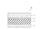
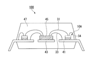
- FIG. 1 is a diagram illustrating an example of a method of using the adhesive tape 10.
- FIG. is sectional drawing which shows typically the adhesive tape of 2nd embodiment of this invention.
- adhesive tape for electronic parts of the present invention (hereinafter also simply referred to as “adhesive tape”) will be described with reference to the accompanying drawings.
- FIG. 1 is a cross-sectional view schematically showing the adhesive tape 10 of the first embodiment of the present invention.
- the adhesive tape 10 is formed by laminating a metal layer 1, a first adhesive layer 3, an insulating layer 5, and a second adhesive layer 7 in this order.
- Metal layer As a metal which comprises the metal layer 1, copper, white copper, silver, iron, 42 alloy, stainless steel, aluminum, palladium, nickel etc. are mentioned, for example.
- the metal layer 1 may be a single layer or a multilayer.
- a multilayer metal layer what is comprised from the layer which consists of metal foils, such as copper foil, and the plating layer laminated
- the metal constituting the plating layer is preferably gold, silver, platinum, palladium, aluminum, or the like from the viewpoint that wire bonding can be satisfactorily performed.
- the thermal expansion coefficient of the metal layer 1 at 50 to 200 ° C. is preferably 3 to 50 ppm / ° C., more preferably 5 to 40 ppm / ° C. If it is out of the above range, the difference in thermal expansion from the insulating layer or the metal that is the adherend becomes large, and there is a risk that warpage is likely to occur in the production as a tape or in the assembly process of the lead frame and the semiconductor device.
- the aluminum purity in the metal layer 1 is preferably 90% or more, more preferably 95% or more, and even more preferably 99% or more from the viewpoint that direct wire bonding can be performed.
- Examples of the aluminum alloy having an aluminum purity of 90% or more include 1N30, 1085, 3003, and 8076.
- the thickness of the metal layer 1 is 200 ⁇ m or less, preferably 150 ⁇ m or less, more preferably 100 ⁇ m or less, further preferably 60 ⁇ m or less, and particularly preferably 30 ⁇ m or less. If the thickness of the metal layer 1 is not more than the above upper limit value, the workability of the adhesive tape 10 is excellent. From the viewpoint of fine wiring formation, the metal layer 1 is preferably thinner. The thickness of the metal layer 1 is preferably 0.5 ⁇ m or more, more preferably 3 ⁇ m or more, and further preferably 5 ⁇ m or more. If the thickness of the metal layer 1 is not less than the above lower limit value, the metal layer 1 has sufficient mechanical strength and is not easily broken during wire bonding.
- the first adhesive layer 3 is a layer that bonds the metal layer 1 and the insulating layer 5 and is formed of an adhesive.
- the storage elastic modulus at 200 ° C. after the heat treatment at 175 ° C. for 1 hour of the first adhesive layer 3 is 1 ⁇ 10 6 Pa or more, preferably 6 ⁇ 10 6 Pa or more, more preferably 1 ⁇ 10 7 Pa or more. Preferably, 6 ⁇ 10 7 Pa or more is more preferable.
- the first adhesive layer 3 sufficiently holds the metal layer 1 during wire bonding, and the wire bonding property of the adhesive tape 10 is excellent.
- the tape on the wiring has a part that is in the state of air printing (the tape on the inner lead serves as a support under the tape. There is an inner lead, but the tape above the inner lead and the inner lead has no support below). It is assumed that wire bonding is also applied to the part in such a state. Also in this case, in order to sufficiently support the metal layer 1, it is preferable that the storage modulus of the first adhesive layer 3 is higher. Furthermore, in recent years, for the purpose of reducing the cost of semiconductor devices, the use of copper or palladium-coated copper instead of gold as a wire material is increasing.
- the wire bonding conditions are more severe (high load, high temperature).
- the first adhesive layer 3 has a higher storage elastic modulus. The higher the storage elastic modulus of the first adhesive layer 3 after the heat treatment is, the better, and the upper limit is not particularly limited.
- the storage elastic modulus can be adjusted by the type and composition of the components contained in the adhesive forming the first adhesive layer 3.
- the heat treatment is performed by using a material containing a thermoplastic polyimide component such as a thermoplastic polyimide resin or a thermoplastic polyamideimide resin. Later storage modulus can be increased.
- the first adhesive layer 3 is formed from a thermosetting adhesive, which will be described later, by using an adhesive mainly composed of a thermosetting resin component such as an epoxy resin, a phenol resin, or a melamine resin, etc.
- the storage elastic modulus after heat treatment can be increased.
- an adhesive having a storage elastic modulus at 200 ° C. of 1 ⁇ 10 6 Pa or more after heat treatment at 175 ° C. for 1 hour is appropriately selected from known adhesives. Can be used.
- the adhesive include a thermoplastic adhesive and a thermosetting adhesive.
- the first adhesive layer 3 may be a layer formed from a thermoplastic adhesive, or may be a layer formed from a thermosetting adhesive.
- thermoplastic adhesive A well-known thing can be used as a thermoplastic adhesive, For example, what contains a thermoplastic resin component (heat-fusion resin component) is mentioned.
- thermoplastic resin component include thermoplastic polyimide resin, thermoplastic polyester resin, thermoplastic polyamide resin, polystyrene, poly (meth) acrylate resin, and the like.
- thermoplastic polyimide resins containing a polyimide component are preferable from the viewpoints of heat resistance and adhesiveness.
- the thermoplastic polyimide resins can be selected from various known ones, and examples thereof include thermoplastic polyimide resins, thermoplastic polyamideimide resins, thermoplastic polyesterimide resins, and thermoplastic polyetherimide resins.
- thermoplastic polyimide resin is obtained by cyclization polycondensation of a tetracarboxylic anhydride and a diamine compound.
- the tetracarboxylic dianhydride include 3,3 ′, 4,4′-diphenylsulfone tetracarboxylic dianhydride, 2,3,3 ′, 4′-biphenyltetracarboxylic dianhydride, 3, 3 ', 4,4'-biphenyltetracarboxylic dianhydride, 2,2', 3,3'-biphenyltetracarboxylic dianhydride, 3,3 ', 4,4'-benzophenonetetracarboxylic dianhydride 2,2 ′, 3,3′-benzophenone tetracarboxylic dianhydride, 2,2 ′, 3,3′-diphenyl ether tetracarboxylic dianhydride, 2,3 ′, 3,4′-diphenyl ether
- diamine compound examples include 3,4'-diaminodiphenyl ether, 4,4'-diaminodiphenyl ether, 3,3'-dimethyl-4,4'-diaminodiphenyl ether, 3,3'-diaminodiphenyl ether, 4,4'-diamino.
- siloxane compounds having amino groups at both ends 1,3-bis (3-aminopropyl) -1,1,3,3-tetramethyldisiloxane, ⁇ , ⁇ -bis (3-aminopropyl) polysiloxane Dimethylsiloxane (for example, tetramer to octamer of aminopropyl-terminated dimethylsiloxane), 1,3-bis (3-aminophenoxymethyl) -1,1,3,3-tetramethyldisiloxane, ⁇ , ⁇ -bis (3-aminophenoxymethyl) polydimethylsiloxane, 1,3-bis (2- (3-aminophenoxy) ethyl) -1,1,3,3-tetramethyldisiloxane, ⁇ , ⁇ -bis ( 2- (3-Aminophenoxy) ethyl) polydimethylsiloxane, 1,3-bis (3- (3-aminophenoxy) propyl) -1,1,1,
- polysiloxanes having an average polymerization degree of 2 to 33 (molecular weight of about 250 to 3000), preferably an average polymerization degree of 4 to 24 (molecular weight of about 400 to 2000) are used. Is done.
- diamine compound having an epoxy reactive group examples include 2,5-dihydroxy-p-phenylenediamine, 3,3′-dihydroxy-4,4′-diaminodiphenyl ether, 4,3′-dihydroxy-3,4′-.
- thermoplastic polyimide resin examples include the following (1) to (3).
- TPER 1,3-bis (4-aminophenoxybenzene)
- 3,3 ′, 4,4′-biphenyltetracarboxylic dianhydride hereinafter referred to as s
- At least one selected from the group consisting of -BPDA and 2,3,3 ', 4'-biphenyltetracarboxylic dianhydride (hereinafter also abbreviated as a-BPDA).
- the molar ratio of s-BPDA / a-BPDA is preferably 100/0 to 5/95.
- Adhesion is improved by including a-BPDA.
- DANPG 1,3-bis (4-aminophenoxy) -2,2-dimethylpropane
- ODPA 4,4′-oxydiphthalic dianhydride
- polyimide resin produced from a-BPDA A polyimide resin produced from TPER, ODPA and pyromellitic dianhydride.
- thermoplastic polyimide resins (1) to (3) may be replaced with other tetracarboxylic dianhydrides as long as the physical properties of the thermoplastic polyimide resin are not impaired.
- s-BPDA and a-BPDA in the thermoplastic polyimide resin (1) and ODPA in the thermoplastic polyimide resins (2) to (3) are 2,2-bis (3,4-dicarboxyphenyl) propane. It may be replaced with dianhydride or 2,3,6,7-naphthalenetetracarboxylic dianhydride.
- the ODPA in the thermoplastic polyimide resins (2) to (3) may be replaced with s-BPDA.
- the diamine in each of the thermoplastic polyimide resins (1) to (3) may be replaced with another diamine as long as the physical properties of the thermoplastic polyimide are not impaired.
- examples of other diamines include 4,4′-diaminodiphenyl ether, 4,4′-diaminobenzophenone, 4,4′-diaminodiphenylmethane, 2,2-bis (4-aminophenyl) propane, and 1,4-bis.
- Examples of the siloxane compound having an amino group at both terminals include compounds represented by the formula (4-1) or (4-2) described later.
- the ratio of the aromatic diamine is preferably 20 mol% or less, particularly preferably 10 mol% or less, based on the total diamine.
- the ratio of the aliphatic diamine and the siloxane compound is preferably 20 mol% or less, more preferably 15 mol% or less, based on the total diamine. If this ratio is exceeded, the heat resistance of the thermoplastic polyimide resin is lowered. Moreover, the storage elastic modulus after the said heat processing of the 1st contact bonding layer 3 falls.
- thermoplastic polyimide resin is obtained by reacting each of the above components with another tetracarboxylic dianhydride and another diamine in an organic solvent at a temperature of about 100 ° C. or less, particularly 20 to 60 ° C.
- a polyamic acid solution using the polyamic acid solution as a dope solution, forming a thin film of the dope solution, evaporating and removing the solvent from the thin film, and cyclizing the polyamic acid with imide Can do.
- the polyamic acid solution prepared as described above is heated to 150 to 250 ° C., or an imidizing agent is added and reacted at a temperature of 150 ° C. or less, particularly 15 to 50 ° C.
- thermoplastic polyimide resin can be produced. Thereafter, the solvent is evaporated or precipitated in a poor solvent to form a powder, and then the powder is dissolved in an organic solution to obtain an organic solvent solution of thermoplastic polyimide.
- a dicarboxylic acid anhydride may be used to seal the amine end of the thermoplastic polyimide. Examples of the dicarboxylic acid anhydride include phthalic anhydride and substituted products thereof, hexahydrophthalic anhydride and substituted products thereof, succinic anhydride and substituted products thereof, and phthalic anhydride is preferable.
- organic solvent used in the production of the polyamic acid examples include N-methyl-2-pyrrolidone, N, N-dimethylformamide, N, N-dimethylacetamide, N, N-diethylacetamide, dimethyl sulfoxide, and hexamethyl.
- organic solvents include phosphoramide, N-methylcaprolactam, cresols and the like. These organic solvents may be used alone or in combination of two or more.
- the amount of diamine (as the number of moles of amino group) used is the total number of moles of acid anhydride (as the acid anhydride groups of tetracarboxylic dianhydride and dicarboxylic anhydride).
- the molar ratio with respect to the total mole) is preferably 0.95 to 1.0, more preferably 0.98 to 1.0, and particularly preferably 0.99 to 1.0. It is preferable that the usage-amount of dicarboxylic acid anhydride is 0.05 or less as molar ratio with respect to the molar amount of the acid anhydride group of tetracarboxylic dianhydride.
- a phosphorus stabilizer can be added during the polymerization of the polyamic acid for the purpose of limiting the gelation of the polyamic acid.
- the phosphorus stabilizer include triphenyl phosphite and triphenyl phosphate.
- the addition amount is preferably in the range of 0.01 to 1% by mass with respect to the solid content (polymer).
- a basic organic compound can be added to the dope solution.
- the basic organic compound examples include imidazole, 2-imidazole, 1,2-dimethylimidazole, 2-phenylimidazole, benzimidazole, isoquinoline, substituted pyridine and the like.
- the addition amount is preferably 0.05 to 10% by mass, more preferably 0.1 to 2% by mass with respect to the polyamic acid. Since these form a polyimide film at a relatively low temperature, they can be used to avoid insufficient imidization.
- an organoaluminum compound, an inorganic aluminum compound or an organotin compound may be added to the dope solution.
- aluminum hydroxide, aluminum triacetylacetonate or the like can be added in an amount of 1 ppm or more, particularly 1 to 1000 ppm as aluminum metal with respect to polyamic acid.
- the glass transition temperature (Tg) of the thermoplastic polyimide resins is preferably 150 to 350 ° C., more preferably 190 to 350 ° C., and further preferably 200 to 280 ° C.
- Tg The glass transition temperature
- the first adhesive layer 3 contains a thermoplastic polyimide resin having a glass transition temperature of 150 to 350 ° C., wire bondability, heat resistance, high-temperature adhesive strength with the metal layer 1 and workability with the metal layer are excellent.
- a glass transition temperature is measured by the method as described in the Example mentioned later.
- thermoplastic resin component contained in the thermoplastic adhesive may be one type or two or more types.
- a thermoplastic adhesive may further contain other components other than a thermoplastic resin component as needed.
- thermoplastic adhesive is usually used as a liquid thermoplastic adhesive containing a thermoplastic resin component and a liquid medium such as an organic solvent.
- the first adhesive layer 3 is formed by applying such a liquid thermoplastic adhesive to the insulating layer 5 or the metal layer 1 and drying.
- thermosetting adhesive A known thermosetting adhesive can be used as the thermosetting adhesive.
- the thermosetting adhesive here refers to an adhesive containing a component (thermosetting resin) that is cured by heating.
- Thermosetting resin components include epoxy resin, phenol resin, resorcinol resin, melamine resin, urea resin, maleimide resin, benzoguanamine resin, acetoguanamine resin, unsaturated polyester resin, diallyl phthalate resin, xylene resin, furan resin, isocyanate Resin etc. can be illustrated. These resins may be used alone or in combination of two or more. Among these, it is preferable to contain an epoxy resin, a phenol resin, or a maleimide resin.
- the adhesive layer can have a high elastic modulus at a processing temperature in the wire bonding process. Moreover, the adhesive layer with high adhesive strength with the metal layer 1 is obtained under the high temperature in a semiconductor device assembly process by containing an epoxy resin or a phenol resin.
- the thermosetting adhesive can further contain a curing agent or a curing accelerator of a thermosetting resin component as necessary.
- the thermosetting adhesive can further contain a thermoplastic component.
- the thermoplastic component includes acrylonitrile-butadiene copolymer (NBR), acrylonitrile-butadiene-styrene resin (ABS), styrene-butadiene-ethylene resin (SEBS), styrene-butadiene-styrene resin (SBS), polybutadiene, polyacrylonitrile.
- thermoplastic polyimide polyvinyl butyral, polyamide, polyamideimide, thermoplastic polyimide, polyester, polyurethane, acrylic rubber and the like.
- thermoplastic polyimide its own heat resistance is high, and when combined with a thermosetting component, the heat resistance of the adhesive layer can be further improved (thermoplastic polyimide, etc.), flexible and other resin Those that are easy to mix and easily improve the film forming property of the adhesive layer alone (polyamide resin, acrylonitrile-butadiene copolymer, acrylic copolymer, polyurethane, etc.) are preferred.
- thermosetting adhesive [(I), (II)]. However, the present invention is not limited to this.
- thermosetting adhesive (I) any known acrylonitrile-butadiene copolymer can be used. From the viewpoint of heat resistance and processability to paint, those having a weight average molecular weight of 50,000 to 1,000,000 and an acrylonitrile content of 5 to 50% by weight are preferred, and the weight average molecular weight is 100,000 to 500. And acrylonitrile content of 10 to 40% by mass is particularly preferable. If the weight average molecular weight of the acrylonitrile-butadiene copolymer is not less than the lower limit of the above range, the heat resistance is good, and if it is not more than the upper limit of the above range, the processing into a paint is good.
- the weight average molecular weight of the acrylonitrile-butadiene copolymer is a value measured by gel permeation chromatography [GPC] (standard sample: polystyrene).
- the acrylonitrile content is the ratio of acrylonitrile units to the total mass of the acrylonitrile-butadiene copolymer.
- other thermoplastic components such as an acrylic copolymer and urethane rubber may be used.
- the epoxy resin is a compound having two or more oxirane rings in the molecule, and examples thereof include glycidyl ether, glycidyl ester, glycidyl amine, linear aliphatic epoxide, and alicyclic epoxide. Any of these may be used alone or in combination of two or more.
- the epoxy resin include bifunctional epoxy resins such as bisphenol A type epoxy resin, bisphenol F type epoxy resin, bisphenol S type epoxy resin, and naphthalene type epoxy resin; triglycidyl isocyanurate type epoxy resin, triglycidyl-p- Polyfunctional glycidylamine type epoxy resins such as aminophenol type epoxy resin, tetraglycidyl diaminodiphenylmethane type epoxy resin, tetraglycidyl metaxylenediamine type epoxy resin, tetraglycidyl-1,3-bisaminomethylcyclophene type epoxy resin; Polyfunctional glycidyl ether type epoxy resins such as tetraphenyl glycidyl ether type epoxy resin, triphenyl glycidyl ether methane type epoxy resin; phenol type epoxy resin, al Multifunctional resol type epoxy resins such as Le phenol epoxy resin; cyclopentadiene type epoxy resins, biphenyl type epoxy resin
- the epoxy equivalent of the epoxy resin is preferably 100 to 4000, more preferably 100 to 2000, and particularly preferably 100 to 1000.
- the epoxy equivalent is less than 100, an uncured portion tends to remain and easily causes foaming. If the epoxy equivalent is greater than 4000, it is difficult to dissolve in a solvent, and compatibility with other resins tends to deteriorate.
- epoxy resin a commercially available product can be used, and specifically, manufactured by Mitsubishi Chemical Corporation: trade name; Epicoat 806, 828, 834, 1001 (above, bisphenol type), YX-4000, YX-4000H ( Biphenyl type) and other bifunctional epoxy resins; Epicoat 152, 154, 180S65, 1032H60, 157S70 (polyfunctional novolak type), 604 (tetraglycidyldiphenylmethane type), DIC Corporation: Trade names: HP-7200, HP-7200H (Dicyclo type), etc., manufactured by Nippon Kayaku Co., Ltd .: Trade names; EOCN-102S, EOCN-103S, EOCN-104S, EOCN-1020 (o-cresol novolak type), EPPN-501H, EPPN-502H (triphenylmethane type) ) And other polyfunctional epoxy resins; It is.
- a halogenated epoxy resin can be used as the epoxy resin.
- Use of halogenated epoxy resins, particularly brominated epoxy resins, is an effective means for imparting flame retardancy.
- Specific examples of brominated epoxies include Mitsubishi Chemical Co., Ltd .: trade name; Epicoat 5045, 5046, 5050, Nippon Kayaku Co., Ltd .: trade name: BREN-S, BREN-105, BREN-301, and the like. There is no problem even if a phosphide epoxy resin or the like is used instead of the halogenated epoxy resin.
- the maleimide resin is a compound having two or more maleimide groups in the molecule, and examples thereof include compounds represented by the following formulas (3-1) to (3-6). These compounds are generally commercially available and can be easily obtained. It can also be synthesized by a conventionally known method.
- the phenol resin reacts with an epoxy resin or a maleimide resin to form a three-dimensional network structure.
- the phenol resin all known resins can be used, the adhesive temperature, the curing temperature of the adhesive can be lowered, and sufficient adhesive strength can be obtained, so that the phenol component is pt-butylphenol, bisphenol A, A pt-butylphenol type, bisphenol A type, cresol type, or a co-condensation type resol type phenol resin consisting of at least one selected from the group consisting of cresol is preferred.
- the thermosetting adhesive (I) may contain a curing (acceleration) agent as necessary.
- the “curing (accelerating) agent” indicates a curing agent or a curing accelerator.
- examples of the curing (accelerating) agent include organic peroxides, imidazoles, phosphorus-based catalysts (such as triphenylphosphine), and diamine compounds.
- organic peroxide examples include diazabicyclooctane, methyl ethyl ketone peroxide, cyclohexane peroxide, 3,3,5-trimethylcyclohexanone peroxide, methylcyclohexanone peroxide, methyl acetoacetate peroxide, acetylacetone peroxide, 1,1 -Bis (t-butylperoxy) -3,3,5 trimethylhexane, 1,1-bis (t-butylperoxy) -cyclohexane, 2,2-bis (t-butylperoxy) octane, n-butyl -4,4-bis (t-butylperoxy) valate, 2,2-bis (t-butylperoxy) butane, t-butyl hydroperoxide, cumene hydroperoxide, di-isopropylbenzene hydroperoxide, p -men Hydroperoxide, 2,5-dimethylhexane
- imidazoles examples include 1,2-dimethylimidazole, 1-methyl-2-ethylimidazole, 2-methylimidazole, 2-ethyl-4-methylimidazole, 2-undecylimidazole, 2-heptadecylimidazole, and 2-phenyl.
- Imidazole 1-benzyl-2-methylimidazole, 1-benzyl-2-phenylimidazole, 1-benzyl-2-phenylimidazole trimellitic acid salt, 1-benzyl-2-ethylimidazole, 1-benzyl-2-ethyl -5-methylimidazole, 2-ethylimidazole, 2-isopropylimidazole, 2-phenyl-4-benzylimidazole, 1-cyanoethyl-2-methylimidazole, 1-cyanoethyl-2-ethyl-4-methylimidazole, 1-cyanoethyl - -Undecylimidazole, 1-cyanoethyl-2-isopropylimidazole, 1-cyanoethyl-2-phenylimidazole, 1-cyanoethyl-2-methylimidazolium trimellitate, 1-cyanoethyl-2-phenylimidazolium trimellitate, 2 ,
- the diamine compound reacts and cures with an epoxy resin or a maleimide resin, and has an effect of improving the heat resistance of the adhesive layer.
- Examples of the diamine compound include compounds represented by the following formula (5-1). H 2 N—R 2 —NH 2 (5-1) (In the formula, R 2 represents a divalent aliphatic group, aromatic group or alicyclic group.)
- R 2 is the same as R 1 described above.
- Specific examples of the compound represented by the formula (5-1) include 3,3′-diaminobiphenyl, 3,4′-diaminobiphenyl, 4,4′-diaminobiphenyl, 3,3′-diaminodiphenylmethane, 3 , 4'-diaminodiphenylmethane, 4,4'-diaminodiphenylmethane, 2,2- (3,3'-diaminodiphenyl) propane, 2,2- (3,4'-diaminodiphenyl) propane, 2,2- ( 4,4'-diaminodiphenyl) propane, 2,2- (3,3'-diaminodiphenyl) hexafluoropropane, 2,2- (3,4'-diaminodiphenyl) hexafluoropropane, 2,2- (4 , 4'-diaminodiphenyl) hexaflu
- the diamine compound is preferably a siloxane compound having amino groups at both ends, such as a compound represented by the following formula (4-1) or (4-2).
- a siloxane compound having amino groups at both ends such as a compound represented by the following formula (4-1) or (4-2).
- R 1 represents a divalent aliphatic group, aromatic group or alicyclic group
- Ph represents a phenyl group
- m and n each represents an integer of 0 to 10.
- Examples of the divalent aliphatic group for R 1 include an alkylene group.
- the alkylene group preferably has 1 to 10 carbon atoms, and more preferably 1 to 7 carbon atoms.
- Specific examples of the compound represented by the formula (4-1) or (4-2) include bis (3-aminopropyl) tetramethyldisiloxane, aminopropyl-terminated dimethylsiloxane tetramer, octamer, bis (3-aminophenoxymethyl) tetramethyldisiloxane and the like.
- the thermosetting adhesive (I) may contain a cross-linking agent, an additive, a modifier, a processing aid, a filler, and the like as necessary.
- the crosslinking agent include the organic oxides.
- the additive include an antioxidant for improving heat resistance, a flame retardant for imparting flame retardancy, and an antistatic agent.
- examples of the antioxidant include IRGANOX 1010 and IRGANOX 1076 manufactured by Ciba Specialty Chemicals, and examples of the flame retardant include inorganic filler type products such as aluminum hydroxide, and ADEKA ADEKA STAB FP-600. Phosphate ester type and the like can be mentioned.
- the filler include organic fillers and inorganic fillers.
- organic fillers and inorganic fillers can be used.
- alumina, silicon nitride, boron nitride and the like are for the purpose of imparting insulation and thermal conductivity
- metal powders such as silver, copper and nickel are for the purpose of imparting thermal conductivity
- titanium oxide, Calcium carbonate, silica, zinc oxide, magnesium oxide and the like can be contained for the purpose of adjusting dielectric properties, coefficient of thermal expansion, viscoelasticity, and tackiness.
- the total of the epoxy resin or maleimide resin and the phenol resin is preferably 40 to 700 parts by mass with respect to 100 parts by mass of the acrylonitrile-butadiene copolymer. More preferably, it is part by mass.
- the elastic modulus after curing becomes high, heat resistance and wire bondability are good, and are not more than the upper limit of the above range.
- the film on the B stage is not easily fragile, and workability and workability are good.
- the ratio of the epoxy resin to the phenol resin is preferably from 1: 3 to 1: 0.1, more preferably from 1: 1.5 to 1: 0.3 in terms of functional group equivalent ratio. If the ratio of phenol resin is too small, the cured product tends to be brittle and adhesive strength tends to decrease. If the ratio of phenol resin is too large, the elastic modulus after curing tends to decrease, and heat resistance and wire bondability tend to decrease. .
- the ratio of the maleimide resin to the phenol resin is preferably a functional group equivalent ratio of 1: 2 to 1: 0.1, more preferably 1: 1.5 to 1: 0.3. If the ratio of phenol resin is too small, the cured product tends to be brittle and adhesive strength tends to decrease. If the ratio of phenol resin is too large, the elastic modulus after curing tends to decrease, and heat resistance and wire bondability tend to decrease. .
- a diamine compound When using a maleimide resin, it is preferable to use a diamine compound as a crosslinking agent.
- the content of the diamine compound is preferably 0.01 to 2 molar equivalents or less in terms of the functional group equivalent ratio of the maleimide resin. If the content of the diamine compound is not less than the above lower limit value, the strength of the adhesive layer is good and the processability as a tape is good, and the adhesiveness with the insulating layer 5 is also good, and if it is not more than the above upper limit value.
- the adhesive layer is used as a paint, it is possible to prepare the paint without causing gel in the paint.
- the content of the filler is preferably 1 to 70% by mass and more preferably 5 to 50% by mass with respect to the total solid content of the thermosetting adhesive. If the filler content exceeds 70% by mass, the processability as an adhesive tape may be deteriorated.
- thermoplastic polyimide resin in the thermosetting adhesive (II) examples include the same as those mentioned for the thermoplastic adhesive.
- examples of the epoxy resin and the phenol resin are the same as those given for the thermosetting adhesive (I).
- thermosetting adhesive (II) may contain a curing (acceleration) agent, a crosslinking agent, an additive, a modifier, a processing aid, a filler, and the like, if necessary.
- thermosetting adhesive (II) examples of the curing (acceleration) agent include imidazoles, phosphorus catalysts (such as triphenylphosphine), and amine catalysts (1,8-diazabicyclo (5,4,0) undecene). Etc.).
- examples of the imidazoles include the same imidazoles as those described for the thermosetting adhesive (I).
- examples of the crosslinking agent, additive, modifier, processing aid, and filler are the same as those described for the thermosetting adhesive (I).
- the total of the epoxy resin and the phenol resin is preferably 0.1 to 300 parts by mass, and 0.5 to 200 parts by mass with respect to 100 parts by mass of the thermoplastic polyimide resin. More preferably, it is a part.
- the storage elastic modulus after the adhesive is cured is high, the heat resistance and wire bondability are good, and the upper limit of the above range is not exceeded.
- the mechanical strength in the B stage and C stage of an adhesive agent is not impaired, a film
- the ratio of the epoxy resin to the phenol resin is preferably 1: 1.5 to 1: 0.1, more preferably 1: 1.1 to 1: 0.3, in terms of functional group equivalent ratio. If the ratio of the phenol resin is too small, the cured product tends to be brittle and the adhesive strength tends to decrease. If the ratio of the phenol resin is too large, the heat resistance decreases.
- a curing agent and curing accelerator for epoxy resin can be included.
- examples thereof include imidazoles, tertiary amines, phenols, dicyandiamides, aromatic diamines, and organic peroxides.
- the filler content is preferably 4 to 40% by mass and more preferably 9 to 24% by mass with respect to the total solid content of the thermosetting adhesive. If the filler content is not less than the lower limit of the above range, the effect of stabilizing the taping characteristics is sufficiently exhibited, and if it is 40% by mass or less, the adhesion strength of the adhesive layer, the workability of the adhesive tape, etc. are good. is there.
- thermosetting adhesive (I) or (II) is usually used as a liquid thermosetting adhesive containing the above components and a liquid medium such as an organic solvent.
- the first adhesive layer 3 is formed by applying such a liquid thermosetting adhesive to the insulating layer 5 or the metal layer 1 and drying. At this time, the first adhesive layer 3 may be in a semi-cured state.
- the method for controlling the semi-cured state is not limited, but is preferably controlled by aging or the like.
- liquid medium examples include N-methyl-2-pyrrolidone, N, N-dimethylacetamide, N, N-dimethylformamide, dimethyl sulfoxide, sulfolane, hexamethylphosphoric triamide, 1,3-dimethyl-2-imidazolidone, Hexane, benzene, toluene, xylene, methyl ethyl ketone, acetone, diethyl ether, tetrahydrofuran, dioxane, 1,2-dimethoxyethane, diethylene glycol dimethyl ether, methyl cellosolve, cellosolve acetate, methanol, ethanol, propanol, isopropanol, methyl acetate, ethyl acetate, acetonitrile , Methylene chloride, chloroform, carbon tetrachloride, chlorobenzene, dichlorobenzene, dichloroethane, trichloroe
- the thickness of the first adhesive layer 3 is preferably 1 to 50 ⁇ m, and more preferably 5 to 35 ⁇ m. If the thickness of the 1st contact bonding layer 3 is more than the said lower limit, adhesiveness with the metal layer 1 is favorable, and if it is below the said upper limit, wire bondability is favorable. If the thickness of the first adhesive layer 3 is too thick, the wire bondability may be reduced.
- the material of the insulating layer 5 is not particularly limited, and heat resistance such as polyimide, polyamide, polyether ether ketone, polyether sulfone, polyphenylene sulfide, polyether resin, polyarylate, polyparabanic acid, polyethylene terephthalate, polyethylene naphthalate, etc. Resin film; composite heat-resistant film such as epoxy resin-glass cloth, epoxy resin-polyimide-glass cloth; paper, woven fabric, non-woven fabric, and the like.
- the insulating layer 5 is preferably a non-thermoplastic polyimide film from the viewpoints of heat resistance, insulation, and processability.
- the thickness of the insulating layer 5 is preferably 5 ⁇ m or more, more preferably 7 to 125 ⁇ m, and even more preferably 10 to 75 ⁇ m.
- the thickness of the insulating layer 5 is equal to or greater than the above lower limit value, it is easy to ensure insulation between the metal layer and the adherend (lead frame or the like) even after the adhesive tape is processed such as punching.
- the adhesive tape 10 has sufficient stiffness and is easy to handle.
- the thickness of the insulating layer 5 is not more than the above upper limit value, it is easy to perform processing such as punching.
- the tensile elastic modulus of the insulating layer 5 is preferably 100 to 700 MPa. If the tensile elastic modulus is within the above range, sufficient stiffness can be obtained for the adhesive tape, and the workability during the production of the adhesive tape (lamination with the metal layer 1 or application of an adhesive, etc.) is improved, and the lead frame, etc. The pasting processability to the adherend is also improved.
- the linear expansion coefficient (50 to 200 ° C.) (MD) of the insulating layer 5 is preferably 1 ⁇ 10 ⁇ 6 / ° C. to 40 ⁇ 10 ⁇ 6 / ° C., and 3 ⁇ 10 ⁇ 6 / ° C. to 30 ⁇ 10 -6 / ° C is more preferable.
- the lead frame is generally made of copper. If the linear expansion coefficient of the insulating layer 5 is within the above range, the linear expansion coefficient with copper as the adherend is close, distortion due to heating is less likely to occur, and the workability of the lead frame and the package is improved. . When using aluminum or an aluminum alloy as the metal layer 1, it is preferable to use one having a smaller linear expansion coefficient.
- the second adhesive layer 7 is a layer to be bonded to an adherend (lead frame or the like) when the adhesive tape 10 is used, and is disposed on the outermost layer opposite to the metal layer side.
- the second adhesive layer 7 is formed from an adhesive.
- an adhesive for forming the second adhesive layer 7 a known adhesive can be appropriately selected and used.
- the adhesive include a thermoplastic adhesive and a thermosetting adhesive.
- the second adhesive layer 7 may be a layer formed from a thermoplastic adhesive or a layer formed from a thermosetting adhesive. Examples of the thermoplastic adhesive and the thermosetting adhesive are the same as those described in the section of the first adhesive layer 3.
- thermoplastic adhesives include carboxylic acid anhydrides (tetracarboxylic acid anhydrides, tricarboxylic acid anhydrides, dicarboxylic acid anhydrides), polyamideimide resins obtained from diamines and diisocyanates; carboxylic acid anhydrides (tetracarboxylic acid anhydrides).
- thermosetting adhesive in addition, a composition containing a thermoplastic resin exemplified by the thermoplastic adhesive and a thermosetting resin component such as an epoxy resin or a phenol resin; a polyester resin, an epoxy resin, Composition containing phenol resin; Composition containing polyamide resin, epoxy resin or phenol resin; Composition containing carboxyl group-containing acrylonitrile-butadiene copolymer, epoxy resin, maleimide resin, epoxy resin curing agent and silicone compound; And a composition containing a component containing a carboxyl group-containing acrylonitrile-butadiene copolymer, an epoxy resin, a phenol resin, an amine or an acid anhydride as a curing agent.
- a thermoplastic resin exemplified by the thermoplastic adhesive and a thermosetting resin component
- a thermosetting resin component such as an epoxy resin or a phenol resin
- a polyester resin an epoxy resin, Composition containing phenol resin
- the storage elastic modulus of the second adhesive layer 7 after the heat treatment at 175 ° C. for 1 hour does not need to be 1 ⁇ 10 6 Pa or more, and may be less than 1 ⁇ 10 6 Pa.
- the adhesive tape 10 is taped on a lead frame or a board by a lead frame manufacturer or a board manufacturer, or after being affixed by a semiconductor manufacturer, mounted with an IC, resin-sealed, and used as a semiconductor device Is done. At that time, the adhesive tape 10 may be installed directly on the wiring of the semiconductor device. Therefore, the second adhesive layer 7 of the adhesive tape 10 preferably has electrical reliability as a semiconductor level and workability during taping. The electrical reliability means that current leakage and short circuit do not occur under the conditions of a migration test (85 ° C., 85% RH, 5 V applied, 96 hours) described later.
- the softening start temperature of the second adhesive layer 7 is preferably 0 to 300 ° C, more preferably 0 to 260 ° C, and 25 to 220. ° C is more preferable, and 30 to 180 ° C is particularly preferable. If the softening start temperature is not more than the above upper limit value, it can be attached to an adherend such as a lead frame at a relatively low temperature (for example, 25 to 300 ° C. or less), the workability is good, and the lead frame It becomes difficult to damage. If it is more than the said lower limit, there is no stickiness of a tape and the conveyance property at the time of a sticking process is favorable.
- the softening start temperature is measured by differential scanning calorimetry in the case of a thermoplastic adhesive. In the case of a thermosetting adhesive, it is measured by the elastic modulus lowering start temperature by dynamic viscoelasticity measurement.
- the softening start temperature of the 2nd contact bonding layer 7 can be adjusted with the kind, composition, etc. of the component contained in the adhesive agent to form.
- thermosetting adhesive containing an acrylonitrile-butadiene copolymer, a maleimide resin, a phenol resin, and a siloxane compound.
- thermosetting adhesive (III) examples of the acrylonitrile-butadiene copolymer, maleimide resin, phenol resin, and siloxane compound are the same as those described for the thermosetting adhesive (I).
- thermosetting adhesive (III) may contain a curing accelerator, a diamine compound (excluding a siloxane compound), a filler, and the like, if necessary.
- a curing accelerator e.g., a curing accelerator, a diamine compound (excluding a siloxane compound), a filler, and the like.
- the curing accelerator, the diamine compound (excluding the siloxane compound), and the filler are the same as those described for the thermosetting adhesive (I).
- the total of the maleimide resin and the phenol resin is preferably 10 to 900 parts by mass, and 50 to 400 parts by mass with respect to 100 parts by mass of the acrylonitrile-butadiene copolymer. More preferably.
- the sum of the maleimide resin and the phenol resin is not less than the lower limit of the above range, the heat resistance after curing of the adhesive, in particular, the Tg and elastic modulus are improved, which is suitable for the intended use.
- the adhesive layer itself at the B stage or C stage is not brittle, the workability is good, and the adhesion with the insulating layer 5 is also good.
- the ratio of the maleimide resin to the phenol resin is preferably 10:90 to 90:10, more preferably 20:80 to 80:20 in terms of mass ratio. If the ratio of the phenol resin is too small, the cured product tends to be brittle, and if the ratio of the phenol resin is too large, the adhesive force tends to decrease.
- the content of the diamine compound is preferably 0.01 to 2 molar equivalents or less in terms of the functional group equivalent ratio of the maleimide. If the content of the diamine compound is not less than the above lower limit value, the strength of the adhesive layer is good and the processability as a tape is good, and the adhesiveness with the substrate is also good. When the adhesive layer is used as a paint, it is possible to prepare the paint without causing gel in the paint.
- the content of the siloxane compound is preferably 0.001 to 20% by mass or less, and more preferably 0.01 to 10% by mass or less based on the total solid content of the thermosetting adhesive (III).
- the content of the siloxane compound is within the above range, the heat resistance is further improved, and the adhesiveness between the adhesive tape and the adherend (lead frame, glass, etc.) is further improved.
- the content of the filler is preferably 4 to 40% by mass and more preferably 9 to 24% by mass with respect to the total solid content of the thermosetting adhesive. If the filler content is not less than the lower limit of the above range, the effect of stabilizing the taping characteristics will be sufficiently exerted. is there.
- thermosetting adhesive (III) is usually used as a liquid thermosetting adhesive containing the above components and a liquid medium such as an organic solvent.
- the second adhesive layer 7 is formed by applying such a liquid thermosetting adhesive to the insulating layer 5 and drying it. At this time, the second adhesive layer 7 may be in a semi-cured state.
- the method for controlling the semi-cured state is not limited, but is preferably controlled by aging or the like.
- the liquid medium include the same ones as mentioned for the thermosetting adhesive (I).
- the thickness of the second adhesive layer 7 is preferably 5 ⁇ m or more, more preferably 6 to 100 ⁇ m, and particularly preferably 10 to 50 ⁇ m. If the thickness of the second adhesive layer 7 is not less than the lower limit of the above range, the adhesive strength to the adherend is more excellent, and if it is not more than the upper limit of the above range, the workability as a tape is good. .
- the high temperature adhesive strength of the insulating tape 10 is preferably 3 g / cm or more, more preferably 10 g / cm or more, and particularly preferably 30 g / cm or more.
- the high temperature adhesive strength is a value measured by the following measuring method. Measuring method of adhesive strength at high temperature: After heat-treating the adhesive tape for electronic parts at 175 ° C. for 1 hour, the peel strength (g / cm) at 240 ° C. between the metal layer and the insulating layer was measured by a tensile test.
- the adhesive strength at high temperature is measured under the conditions of a peeling angle of 90 degrees and a pulling speed of 50 mm / min, and the value is defined as the adhesive strength at high temperature.
- heating is performed at 175 ° C. for about 30 minutes to 1 hour before wire bonding. If the adhesive strength at high temperature is equal to or higher than the lower limit, void defects are unlikely to occur between the metal layer 1 and the insulating layer 5 in the heating process in the semiconductor device assembly process as described above.
- the upper limit of the adhesive strength at high temperature is not particularly limited.
- the total thickness of the insulating tape 10 (the total thickness of the metal layer 1, the first adhesive layer 3, the insulating layer 5, and the second adhesive layer 7) is preferably 500 ⁇ m or less, more preferably 250 ⁇ m or less, and 150 ⁇ m. The following are particularly preferred: If the total thickness of the insulating tape 10 is not more than the above upper limit value, the workability is more excellent. Further, the insulating tape 10 can be easily applied to the assembly of a thin semiconductor device.
- the thickness obtained by removing the thickness of the metal layer 1 from the total thickness of the insulating tape 10 is preferably 15 ⁇ m or more, and 25 ⁇ m. The above is more preferable. If the thickness excluding the thickness of the metal layer 1 from the total thickness of the insulating tape 10 is equal to or more than the lower limit value, it is easy to ensure insulation between the conductive adherend such as a lead frame and the metal layer 1. . For example, when a punching process is performed on the insulating tape 10, a metal piece derived from the metal layer 1 may be generated.
- the thickness excluding the thickness of the metal layer 1 from the total thickness of the insulating tape 10 is equal to or greater than the lower limit, it is possible to prevent the conductive adherend and the metal layer 1 from being electrically connected by such a metal piece. It's easy to do.
- the adhesive tape 10 is, for example, Applying a liquid thermoplastic or thermosetting adhesive to one surface of the insulating layer 5 and drying to form the first adhesive layer 3; and Laminating the first adhesive layer 3 and the metal layer 1; Applying a liquid thermoplastic or thermosetting adhesive to the other surface of the insulating layer 5 and drying to form a second adhesive layer 7; and It can manufacture with the manufacturing method which has this.
- a normal coating method or printing method can be used as a method of applying the liquid thermoplastic or thermosetting adhesive.
- Specific coating methods include air doctor coating, bar coating, blade coating, knife coating, reverse coating, transfer roll coating, gravure roll coating, kiss coating, cast coating, spray coating, slot orifice coating, calendar coating, dam Examples of the coating method include coating, dip coating, and die coating.
- Specific examples of the printing method include intaglio printing such as gravure printing, stencil printing such as screen printing, and the like.
- the drying temperature for drying the applied liquid adhesive is not particularly limited as long as the liquid medium can be removed. In the case of a thermosetting adhesive, a temperature at which the formed adhesive layer is in a semi-cured state is preferable.
- the surface of the insulating layer 5 (the surface on which the thermoplastic or thermosetting adhesive is applied) such as corona treatment, plasma treatment, primer treatment, sandblasting, etc. It is preferable to perform a treatment for increasing the adhesive strength between the heat resistant film and the adhesive layer.
- the second adhesive layer 7 can also be formed using the same method as the first adhesive layer 3.
- the apparatus is not particularly limited as long as it can be heated and pressurized.
- a single-action press apparatus, a vacuum press, etc. examples thereof include an apparatus, an autoclave apparatus, a hot roll laminating apparatus, and a double belt press apparatus.
- a hot roll laminating apparatus and a double belt press apparatus are preferable because they are suitable for continuous production. Compared to batch production, continuous production is preferable because productivity is improved and loss is reduced.
- the manufacturing method of the adhesive tape 10 is not limited to the above method.
- the first adhesive layer 3 may be formed on the metal layer 1 and the first adhesive layer 3 and the insulating layer 5 may be laminated.
- the first adhesive layer 3 may be formed by laminating the first adhesive layer 3 on the insulating layer 5 after forming a single layer film by an extrusion method or a casting method, in addition to being applied directly to the insulating layer 5.
- the resin component and thermoplastic adhesive which comprise the insulating layer 5 may be coextruded, and the insulating layer 5 and the 1st adhesive layer 3 may be produced at once.
- An insulating base with an adhesive layer in which the first adhesive layer 3 is formed on one surface of the insulating layer 5 is prepared in advance, and the second adhesive layer 7 is formed on the insulating layer 5 of the insulating base with an adhesive layer. May be formed to obtain the adhesive tape 10.
- the method for producing the insulating base with an adhesive layer is not particularly limited.
- a liquid thermoplastic adhesive for example, a thermoplastic polyimide resin
- an insulating layer for example, the above-described heat-resistant resin.
- coating to one side of a film) and drying and the method of bonding the film of a thermoplastic adhesive on both surfaces of an insulating layer are mentioned.
- a liquid thermoplastic adhesive especially when using thermoplastic polyimide as a thermoplastic resin component, for example, it is applied to a heat resistant film in the state of a precursor polyamic acid and then dried.
- a method of imidizing and a method of applying a soluble polyimide resin as it is and drying it a method of forming the first adhesive layer 3 is not particularly limited.
- a method of coextruding the resin constituting each of the first adhesive layer 3 / insulating layer 5 to produce an insulating substrate with an adhesive layer at a time is also mentioned.
- the first adhesive layer 3 is a single layer containing a thermoplastic resin component, it can be obtained by forming a film by a belt casting method, an extrusion method or the like.
- a suitable structure of the insulating base material with an adhesive layer for example, a heat-sealable heat-resistant film in which a thermoplastic polyimide layer is provided on one surface of a non-thermoplastic polyimide film can be mentioned.
- the thickness of the metal layer 1 is 200 ⁇ m or less, and the first adhesive layer 3 that bonds the metal layer 1 and the insulating layer 5 at 200 ° C. after heat treatment at 175 ° C. for 1 hour.
- the storage elastic modulus is 1 ⁇ 10 6 Pa or more, the wire bonding property and the workability are excellent. That is, since the metal layer 1 is thin, it is easy to perform punching or the like.
- the thickness of the metal layer 1 is reduced, the mechanical strength of the metal layer 1 is lowered.
- the storage elastic modulus after the heat treatment of the first adhesive layer 3 is equal to or higher than the lower limit value, it is sufficient at the time of wire bonding.
- the metal layer 1 is less likely to be dented or torn. Therefore, continuous wire bonding can be performed on the metal layer 1. Moreover, if the said storage elastic modulus is more than the said lower limit, the adhesive force at the time of high temperature of the resin component of the 1st contact bonding layer 3 will be high, and there exists a tendency for the heat resistance of the adhesive tape 10 to be excellent. Under high temperature conditions, the first adhesive layer 3, the insulating layer 5, the second adhesive layer 7 and the like generate low molecular weight gas or moisture due to moisture absorption as gas, and the metal layer 1 and the first adhesive layer 3 It may accumulate during this period, resulting in void defects.
- the storage elastic modulus after the heat treatment is not less than the above lower limit value, the adhesiveness of the first adhesive layer 3 to the metal layer 1 is sufficiently high even under high temperature conditions, and void defects can be suppressed. Further, if the storage elastic modulus is not less than the above lower limit value, there is a tendency that warpage due to the difference in thermal expansion between the metal layer 1 and the insulating layer 5 does not easily occur when the temperature change from room temperature to high temperature is repeated. is there. This is presumably because the high storage elastic modulus of the first adhesive layer 3 brakes the displacement due to the thermal expansion of the metal layer 1. In particular, since aluminum or an aluminum alloy has a large coefficient of thermal expansion, the above effect is useful when the metal layer 1 is made of aluminum or an aluminum alloy.
- the adhesive tape 10 is used for assembling electronic components.
- it is suitably used as a lead frame fixing tape.
- the metal layer 1 of the adhesive tape 10 can be used as a bus bar (a conductor wire commonly used for a power source or the like in a semiconductor device).
- FIG. 2 shows an example of how to use the adhesive tape 10.
- the adhesive tape 10 ⁇ / b> A obtained by punching the adhesive tape 10 is stuck on the plurality of inner leads 41 of the lead frame 40 to fix the plurality of inner leads 41.
- a power pad (not shown) of the semiconductor chip 45 installed on the die pad 43 of the lead frame 40 is connected to the metal layer 1 of the adhesive tape 10 ⁇ / b> A via the wire 31.
- a signal pad (not shown) of the semiconductor chip 45 is connected to the inner lead 41 via a wire 33, and a ground pad (not shown) is connected to the die pad 43 via a wire 35.
- the metal layer 1 of the adhesive tape 10A is connected to an inner lead (not shown) for power supply via a wire 34. Further, the adhesive tape 10A can be connected to the ground pad of the semiconductor chip 45 and connected to the inner lead for the ground or the die pad via the wire, and can be used as a bus bar for ground wiring.
- FIG. 3 is a cross-sectional view schematically showing the adhesive tape 20 of the second embodiment of the present invention.
- the adhesive sheet 20 is obtained by laminating the metal layer 1, the first adhesive layer 3, the insulating layer 5, the resin layer 9, and the second adhesive layer 7 in this order.
- the adhesive sheet 20 of the present embodiment is the same as the adhesive tape 10 of the first embodiment except that a resin layer 9 is further provided between the insulating layer 5 and the second adhesive layer 7.
- the resin layer 9 is a layer composed of a resin, and may further include a component other than the resin as necessary. It does not specifically limit as resin which comprises the resin layer 9, A thermoplastic resin, the hardened
- thermoplastic resin examples include a thermoplastic polyimide resin, a thermoplastic polyamideimide resin, a thermoplastic polyester resin, and the like.
- a thermoplastic polyimide resin is more preferable in terms of heat resistance and hygroscopicity.
- a well-known thing can be used as a thermosetting resin.
- epoxy resin, maleimide resin, phenol resin, urea resin, melamine resin, unsaturated polyester, silicone resin and the like can be mentioned. Further, the thermoplastic resin and the thermosetting resin can be mixed and used.
- the resin layer 9 is a layer formed from the same adhesive as the adhesive forming the first adhesive layer 3, and is preferably a layer having a thickness within ⁇ 5 ⁇ m of the first adhesive layer 3, It is particularly preferable that the first adhesive layer 3 is a layer formed from the same adhesive as the adhesive forming the first adhesive layer 3, and the thickness is the same as the thickness of the first adhesive layer 3. If the resin layer 9 is formed from the same material as the first adhesive layer 3 and the thickness of the resin layer 9 is within the above range, the first adhesive layer 3 on one surface of the insulating layer 5 and the resin on the other surface When the layer 9 is provided, the insulating layer 5 hardly warps and the metal layer 1 is easily laminated.
- the preferable high temperature adhesive strength of the insulating tape 20 is the same as that of the insulating tape 10.
- the preferable total thickness of the insulating tape 20 (the total thickness of the metal layer 1, the first adhesive layer 3, the insulating layer 5, the resin layer 9, and the second adhesive layer 7) is the same as that of the insulating tape 10.
- the thickness obtained by removing the thickness of the metal layer 1 from the preferred total thickness of the insulating tape 20 (the total thickness of the first adhesive layer 3, the insulating layer 5, the resin layer 9, and the second adhesive layer 7) is the same as that of the insulating tape 10. It is the same.
- the adhesive tape 20 is, for example, Applying a liquid thermoplastic or thermosetting adhesive to one surface of the insulating layer 5 and drying to form the first adhesive layer 3; and Applying a paint containing a thermoplastic resin or a thermosetting resin and a liquid medium to the other surface of the insulating layer 5 and drying to form a resin layer 9; Laminating the first adhesive layer 3 and the metal layer 1; Applying a liquid thermoplastic or thermosetting adhesive on the resin layer 9 and drying to form the second adhesive layer 7; It can manufacture with the manufacturing method which has this. Either the first adhesive layer 3 or the resin layer 9 may be formed first.
- the formation method of the resin layer 9 is not specifically limited.
- the thermoplastic resin layer may be formed by, for example, forming a heat-melted resin by T-die molding, or a liquid medium such as a thermoplastic resin and an organic solvent.
- the coating layer (for example, the liquid thermoplastic adhesive described above) is applied to the insulating layer 5 and dried. Application and drying of the paint can be performed in the same manner as in the case of forming the first adhesive layer 3.
- a separate film made of a thermoplastic resin can be prepared and laminated with the insulating layer 5 using a laminating method such as a belt press.
- the thermosetting resin layer is, for example, a paint containing a thermosetting resin and a liquid medium such as an organic solvent (for example, the above-described liquid thermosetting adhesive). ) Is applied to the insulating layer 5 and dried.
- a thermosetting resin film can be prepared by applying and drying a paint on a peelable film and then laminated with the insulating layer 5 using a laminating method such as roll laminating.
- the manufacturing method of the adhesive tape 20 is not limited to the above method.
- the first adhesive layer 3 may be formed on the metal layer 1 and the first adhesive layer 3 and the insulating layer 5 may be laminated.
- An insulating base with an adhesive layer in which the first adhesive layer 3 is formed on one surface of the insulating layer 5 and the resin layer 9 is formed on the other surface is prepared in advance, and the resin layer 9 of the insulating base with adhesive layer is prepared.
- the adhesive tape 20 may be obtained by forming the second adhesive layer 7 thereon.
- the method for producing the insulating base with an adhesive layer is not particularly limited.
- a liquid thermoplastic adhesive for example, a thermoplastic polyimide resin
- an insulating layer for example, the above-described heat-resistant resin.
- membrane of a thermoplastic adhesive to both surfaces of an insulating layer are mentioned.
- a liquid thermoplastic adhesive especially when using thermoplastic polyimide as a thermoplastic resin component, for example, it is applied to a heat resistant film in the state of a precursor polyamic acid and then dried.
- first adhesive layer 3 and the resin layer 9 are not particularly limited.
- a method of coextruding resins constituting each of the first adhesive layer 3 / insulating layer 5 / resin layer 9 to produce an insulating substrate with an adhesive layer at a time can be mentioned.
- the first adhesive layer 3 and the resin layer 9 are single layers containing a thermoplastic resin component, they can be obtained by forming a film by a belt casting method, an extrusion method or the like.
- the thickness of the metal layer 1 is 200 ⁇ m or less, and the first adhesive layer 3 that bonds the metal layer 1 and the insulating layer 5 is 175 ° C. for 1 hour.
- the storage elastic modulus at 200 ° C. after the heat treatment is 1 ⁇ 10 6 Pa or more, the wire bonding property and the workability are excellent.
- the said storage elastic modulus is more than the said lower limit, the adhesive force at the time of high temperature of the resin component of the 1st contact bonding layer 3 will be high, and there exists a tendency for the heat resistance of the adhesive tape 20 to be excellent.
- the storage elastic modulus is not less than the above lower limit value, there is a tendency that warpage due to the difference in thermal expansion between the metal layer 1 and the insulating layer 5 does not easily occur when the temperature change from room temperature to high temperature is repeated. is there. Furthermore, since the resin layer 9 is provided, when the adhesive tape 20 is manufactured, the warp of the insulating layer 5 occurs when the first adhesive layer 3 is provided on one surface of the insulating layer 5 and the resin layer 9 is provided on the other surface. The metal layer 1 is easy to be laminated. Similar to the adhesive tape 10, the adhesive tape 20 is used for assembling electronic components.
- the adhesive sheet of the present invention has been described with reference to the embodiment, but the present invention is not limited to the above embodiment.
- Each configuration in the above embodiment, a combination thereof, and the like are examples, and the addition, omission, replacement, and other modifications of the configuration can be made without departing from the spirit of the present invention.
- the metal layer 1 is provided so as to cover the whole of the insulating layer 5 is shown.
- the metal layer 1 is provided so as to cover a part of the insulating layer 5. May be.
- it may be formed narrower than the width of the insulating layer 5 (the width of the insulating tape).
- a protective film may be further provided on the second adhesive layer 7.
- a peelable film can be used as the protective film.
- the peelable film that can be used include a polypropylene film, a fluororesin film, a polyethylene film, a polyethylene terephthalate film, paper, and, in some cases, a film that has been made peelable with a silicone resin.
- the thickness of the peelable film is preferably 1 to 200 ⁇ m, more preferably 10 to 100 ⁇ m.
- the peelable film preferably has a 90 ° peel strength with respect to the second adhesive layer 7 in the range of 0.01 to 10.0 g / cm.
- the peelable film is not easily peeled off when the adhesive tape is processed, and the peelable film is peeled cleanly from the adhesive layer when the adhesive tape is processed, thereby improving workability.
- the 90 ° peel strength is measured by a tensile tester.
- polyimide solution (1) A solution of polyimide resin 1 (polyimide solution (1)) was obtained.
- the glass transition temperature of the polyimide resin 1 was 250 ° C.
- the glass transition temperature was measured by differential scanning calorimetry (hereinafter the same).
- polyimide solution (2) A solution of polyimide resin 2 (polyimide solution (2)) was obtained in the same manner as in Synthesis Example 1 except that the types and blending ratios of diamine and acid anhydride were as shown in Table 1.
- the glass transition temperature of the polyimide resin 2 was 105 ° C.
- THF Tetrahydrofuran
- an acrylonitrile-butadiene copolymer weight average molecular weight 250,000, acrylonitrile content 27% by mass
- a pt-butylphenol type resol phenol resin trade name:
- Example 1 The liquid thermoplastic adhesive A obtained in Preparation Example 1 was applied to one surface of a polyimide film (Ube Industries, Upilex (registered trademark) S, thickness 35 ⁇ m) so that the thickness after drying was 7 ⁇ m. And then dried at 130 ° C. for 10 minutes, and then the other surface is similarly coated with the liquid adhesive A so that the thickness after drying is 7 ⁇ m, and dried to provide an insulating substrate with an adhesive layer.
- Aa was obtained.
- One surface of the produced insulating base material with adhesive layer Aa and aluminum foil manufactured by UACJ, 1N30 material (aluminum purity 99.3%), thickness 30 ⁇ m) are laminated by lamination to obtain a base material with metal layer Aa1.
- the liquid thermosetting adhesive d1 obtained in Preparation Example 5 was applied to one surface of the substrate Aa1 with a metal layer so that the thickness after drying was 20 ⁇ m, and dried at 160 ° C. for 5 minutes. An adhesive tape was obtained.
- Example 2 The liquid thermosetting adhesive B obtained in Preparation Example 2 was applied to one surface of a polyimide film (manufactured by Ube Industries, Upilex S, thickness 50 ⁇ m) so that the thickness after drying was 10 ⁇ m. It was made to dry at 5 degreeC for 5 minute (s), and the insulating base material Ab with an adhesive layer was obtained.
- the adhesive-coated surface of the produced insulating substrate with adhesive layer Ab and an aluminum foil manufactured by UACJ, 1N30 material, 30 ⁇ m
- UACJ 1N30 material, 30 ⁇ m
- the liquid thermosetting adhesive d1 obtained in Preparation Example 5 was applied to the surface opposite to the aluminum foil side of the base material Ab1 with a metal layer so that the thickness after drying was 20 ⁇ m, and the temperature was 160 ° C. It was dried for 5 minutes to obtain an adhesive tape.
- thermosetting adhesive C obtained in Preparation Example 3 was used instead of the thermosetting adhesive B.
- Example 4 The insulating layer in Example 2 was changed to a polyimide film (Ube Industries, Upilex S, thickness 12.5 ⁇ m), the metal layer was changed to aluminum foil (UACJ, 1N30 material, thickness 15 ⁇ m), and an adhesive layer ( An adhesive tape was obtained in the same manner as in Example 2 except that the thickness of D) was changed to 5 ⁇ m.
- a polyimide film Ube Industries, Upilex S, thickness 12.5 ⁇ m
- UACJ aluminum foil
- UACJ 1N30 material, thickness 15 ⁇ m
- An adhesive tape was obtained in the same manner as in Example 2 except that the thickness of D) was changed to 5 ⁇ m.
- Example 5 The insulating layer in Example 2 was changed to a polyimide film (Ube Industries, Upilex S, thickness 125 ⁇ m), the thickness of the adhesive layer (A) was changed to 5 ⁇ m, and the metal layer was aluminum foil (UACJ, 1N30 material) The adhesive tape was obtained in the same manner as in Example 2 except that the thickness was changed to 150 ⁇ m.
- a polyimide film Ube Industries, Upilex S, thickness 125 ⁇ m
- UACJ aluminum foil
- a polyimide film Ube Industries, Upilex S, thickness 5.0 ⁇ m
- the thickness of the adhesive layer (A) was changed to 4 ⁇ m
- the metal layer was made of aluminum foil (UACJ, 1N30 material, thickness 15 ⁇ m)
- an adhesive tape was obtained in the same manner as in Example 2 except that the coating amount of the thermosetting adhesive d1 was changed to an amount such that the thickness after drying was 3 ⁇ m.
- Example 7 A substrate Aa1 with a metal layer was produced in the same manner as in Example 1, and this was used as the adhesive tape of Example 7 as it was.
- Example 8 A substrate Aa1 with a metal layer was produced in the same manner as in Example 1.
- the following liquid thermoplastic adhesive d2 was applied to one surface of the substrate Aa1 with a metal layer so that the thickness after drying was 20 ⁇ m, and dried at 200 ° C. for 3 minutes to obtain an adhesive tape.
- Thermoplastic adhesive d2 polyimide solution obtained in Synthesis Example 3.
- Example 9 An adhesive tape was obtained in the same manner as in Example 1 except that the metal layer in Example 1 was changed to an aluminum foil (manufactured by UACJ, 1085 material (aluminum purity 99.85%), thickness 30 ⁇ m).
- Example 10 The metal layer in Example 2 was applied to one surface of a copper foil (manufactured by JX Nippon Mining & Metals Co., Ltd., BHY-22B-T, thickness 18 ⁇ m) by electroless plating and silver plating with a thickness of 0.5 ⁇ m.
- the adhesive tape was obtained like Example 2 except having changed.
- the copper foil was laminated with the insulating base material Ab with the adhesive layer with the side opposite to the silver-plated side facing the insulating base material Ab with the adhesive layer.
- ⁇ Comparative Example 1> The liquid thermosetting adhesive D obtained in Preparation Example 4 was applied to one surface of a polyimide film (Upilex S, Ube Industries, Ltd., thickness 50 ⁇ m) so that the thickness after drying was 10 ⁇ m, and 100 ° C. And then left at 25 ° C. for 1 week to obtain an insulating base material Ad with an adhesive layer.
- the adhesive-coated surface of the produced insulating base material with adhesive layer Ad and aluminum foil manufactured by UACJ, 1N30 material, thickness of 30 ⁇ m were laminated by lamination to obtain a base material with metal layer Ad1.
- the liquid thermosetting adhesive d1 obtained in Preparation Example 5 is applied to the surface opposite to the aluminum foil side of the base material Ad1 with metal layer so that the thickness after drying is 20 ⁇ m, and the temperature is 160 ° C. It was dried for 5 minutes to obtain an adhesive tape.
- Example 2 An adhesive tape was obtained in the same manner as in Example 1 except that the metal layer in Example 1 was changed to an aluminum material (manufactured by UACJ, 1N30 material, thickness of 300 ⁇ m).
- Example 1 to 10 and Comparative Examples 1 and 2 The layer configurations and physical properties of Examples 1 to 10 and Comparative Examples 1 and 2 are shown in Tables 3 to 4. Moreover, the following evaluation was performed about the adhesive tape obtained by each Example and the comparative example. The results are shown in Tables 3-4.
- the obtained sample was cut into a size of 3 mm in width and 4.5 mm in length, and an inter-sample distance of 40.mm was measured using an elastic modulus measuring device (manufactured by Orientec, dynamic viscoelasticity tester Leo Vibron DDV-01FP).
- the storage elastic modulus was measured at 0 mm, the heating rate was 5 ° C / min, the static tension was 3.0 gf (0.029 N), the excitation frequency was 10 Hz, and the measurement temperature range was 100 ° C to 300 ° C.
- the rate (Pa) was determined.
- Wire bonding test The adhesive tape was attached to a Cu lead frame (for 208 PIN LQFP (for low profile quad flat package)) using the taping machine under the taping conditions shown in Table 2. Next, an epoxy die attach agent was used to attach a dummy chip with a wire pad to the die pad of the lead frame, and heat-cured at 175 ° C. for 1 hour to bond the dummy chip.
- the wire bonding property of the adhesive tape was determined according to the following criteria.
- test sample (1) The adhesive tape was cut into a width of 10 mm and a length of 50 mm and adhered to a copper plate to obtain a test sample (1).
- the crimping conditions were the same as those in Table: Taping conditions.
- the test sample (1) was heat-treated at 175 ° C. for 1 hour (temperature condition: raised from room temperature to 175 ° C. at 2.5 ° C./min) to obtain a test sample (2).
- the state of foaming was visually determined in the same manner as described above (void observation).
- the adhesive tape was cut into a width of 20 mm and a length of 80 mm, and heat-treated at 175 ° C. for 1 hour to obtain a test sample.
- the sample is placed on the heater block at 240 ° C. so that the metal layer side is in contact, and using a tensile tester, the peel strength at 240 ° C. (adhesive strength at high temperature) between the metal layer and the insulating layer (g / cm).
- the measurement was performed at a peeling angle of 90 degrees and a pulling speed of 50 mm / min. Prior to the measurement, the measurement was performed by peeling off one side of the measurement sample in advance by about 10 mm between the metal layer and the insulating layer.
- the heat resistance of the adhesive tape was determined according to the following criteria.
- X There is a void, and the adhesive strength at high temperature is less than 3 g / cm (practically problematic).
- Adhesive tape punching process The adhesive tape was punched into a ring shape by a mold.
- Adhesive tape adhesion process Place the Cu lead frame (for 208PIN LQFP) on the heater block, press the adhesive tape punched into a ring shape with a metal rod, heat and pressurize, and attach the lead frame and adhesive tape Combined.
- the state of the lead frame with the adhesive tape attached is observed with a microscope, the number of metal layers derived from the adhesive tape contacting the lead frame (number of LFs in contact) is counted, and the insulation is evaluated according to the following criteria Went.
- ⁇ The number of touched LFs is 2 pieces or less.
- X The number of LF which contacted is 6 pieces or more.
- Adhesive tape punching process The adhesive tape was punched into a ring shape by a mold.
- Adhesive tape adhesion process Place the Cu lead frame (for 208PIN LQFP) on the heater block, press the adhesive tape punched into a ring shape with a metal rod, heat and pressurize, and attach the lead frame and adhesive tape Combined.
- the above-mentioned lead frame with an adhesive tape was placed in a hot-air circulating oven substituted with nitrogen, and the adhesive tape was cured and thermally cured. The condition was 200 ° C./1 hour.
- a semiconductor package 100 as shown in FIG. 4 was assembled by the following procedure.
- Die bonding The semiconductor chip 45 was bonded to the die pad 43 using a die bonding silver paste and cured at 175 ° C. for 1 hour.
- Wire bonding With wire bonder, wires (gold wires) 31, 33, 34 are wire pads on the semiconductor chip 45 and silver-plated portions at the ends of the inner leads 41, wire pads on the semiconductor chip 45 and metal of the adhesive tape 10A. The metal layer of the adhesive tape 10A and the inner lead for power supply were wired.
- Molding Transfer molding was performed with an epoxy molding agent to form a package 47.
- the semiconductor package 100 was manufactured by performing steps such as homing, die cutting, and plating of the outer lead portion. Next, electricity was passed through the outer lead portion of the semiconductor package 100 obtained as described above, and an electrical reliability test was performed. The electrical reliability test was conducted for 96 hours under conditions of 5 volt application, 85 ° C., and 85% RH. Then, electrical reliability was evaluated according to the following criteria. A case where the resistance value during the test was 1 ⁇ 10 6 or less was judged as a short circuit. ⁇ : No short in 96 hours. X: Short in 96 hours.
- “PI” represents polyimide.
- “A + B + C + D thickness” is the total thickness of the adhesive layer (A), the insulating layer (B), the resin layer (C), and the adhesive layer (D), and the thickness of the metal layer is excluded from the total thickness of the adhesive tape. It is thickness.
- the metal layer, the adhesive layer (A), the insulating layer (B), the resin layer (C), and the adhesive layer (D) are laminated in this order, and the adhesive layer (A) is the first adhesive layer and the adhesive layer (D ) Is the second adhesive layer.
Landscapes
- Chemical & Material Sciences (AREA)
- Organic Chemistry (AREA)
- Chemical Kinetics & Catalysis (AREA)
- Adhesives Or Adhesive Processes (AREA)
- Adhesive Tapes (AREA)
- Wire Bonding (AREA)
- Laminated Bodies (AREA)
Abstract
ワイヤボンディング性および加工性に優れた電子部品用接着テープを提供することを目的とし、金属層1と第一の接着層3と絶縁層5と第二の接着層7とがこの順に積層しており、金属層1の厚みが200μm以下であり、第一の接着層3の、175℃1時間の加熱処理後の200℃における貯蔵弾性率が1×10⁶Pa以上であることを特徴とする電子部品用接着テープを提供する。
Description
本発明は、電子部品用接着テープに関する。
従来、半導体装置を構成する電子部品の組み立てに種々の接着テープが用いられている。例えば、リードフレームの複数のリードピンがワイヤボンディング時の熱等によりばたつくのを抑制するために、複数のリードピンを絶縁性の接着テープ(リードフレーム固定テープ)で固定している。リードフレーム固定テープとしては、ポリイミドフィルム等の絶縁性基材の一方の面に接着層を設けたものが使用されている。
半導体装置の小型化のため、リードフレームにバスバーリードを設け、半導体チップ側にある複数の同電位パッド(電源、グランド等)をバスバーリードに引き出すことが行われている。共通のリードに同電位の配線を引き出すことで、電源やグランドの配線を集約でき、多ピンパッケージを小型化できる。しかし、バスバーリードを設けると、リードフレームのデザインが複雑になる。また、半導体チップとシグナルピンとの間にバスバーリードが配置されることでシグナルピンが遠くなる。
リードフレーム固定テープをワイヤボンディングに利用することが提案されている。
特許文献1では、リードフレームのインナーリード表面に貼着される絶縁性テープの表面に導体膜パターンを形成し、半導体チップのボンディングパッドの少なくとも1つと前記導体膜パターンとをボンディングワイヤを介して接続し、インナーリードの少なくとも1つと前記導体膜パターンとをワイヤ等により電気的に接続することが提案されている。
特許文献2では、複数のインナーリード上に貼り付けるインナーリードテーピング材を、接着材-ポリイミドテープ-接着材-ジュラルミンテープ-銀めっき層の5層構造とし、その銀めっき層と、半導体チップの電極パッドと接続されたインナーリードとをワイヤで接続することが提案されている。
特許文献1では、リードフレームのインナーリード表面に貼着される絶縁性テープの表面に導体膜パターンを形成し、半導体チップのボンディングパッドの少なくとも1つと前記導体膜パターンとをボンディングワイヤを介して接続し、インナーリードの少なくとも1つと前記導体膜パターンとをワイヤ等により電気的に接続することが提案されている。
特許文献2では、複数のインナーリード上に貼り付けるインナーリードテーピング材を、接着材-ポリイミドテープ-接着材-ジュラルミンテープ-銀めっき層の5層構造とし、その銀めっき層と、半導体チップの電極パッドと接続されたインナーリードとをワイヤで接続することが提案されている。
本発明者らの検討によれば、一般的な接着剤を用いて絶縁層に金属層を積層し、金属層/接着層/絶縁層/接着層の構成の接着テープとした場合、金属層とワイヤとを連続でボンディングできないことがある。中には金属層が破れてしまうこともある。このような問題は、金属層の厚さが薄くなるにつれて生じやすくなる。金属層の厚さを厚くすれば、ボンディングはしやすくなるが、接着テープに対して打ち抜き等の加工をしにくくなる。
なお、特許文献1~2では、これらの問題について何ら検討されていない。
なお、特許文献1~2では、これらの問題について何ら検討されていない。
本発明は、上記の事情を鑑みてなされたものであり、ワイヤボンディング性および加工性に優れた電子部品用接着テープを提供することを目的とする。
本発明は、以下の(1)~(10)の構成を有する電子部品用接着テープを提供する。
(1)金属層と、第一の接着層と、絶縁層と、第二の接着層とがこの順に積層しており、
前記金属層の厚みが200μm以下であり、
前記第一の接着層の、175℃1時間の加熱処理後の200℃における貯蔵弾性率が1×10⁶Pa以上であることを特徴とする電子部品用接着テープ。
(2)前記第二の接着層の軟化開始温度が0~300℃である、(1)に記載の電子部品用接着テープ。
(3)総厚みが500μm以下である、(1)又は(2)に記載の電子部品用接着テープ。
(4)下記の測定方法で測定される高温時接着強度が3g/cm以上である、(1)~(3)のいずれかに記載の電子部品用接着テープ。
高温時接着強度の測定方法:電子部品用接着テープに対して175℃1時間加熱処理を行った後、金属層と絶縁層との間の240℃における剥離強度(g/cm)を、引張り試験機を使用して、剥離角度90度、引張り速度50mm/分の条件で測定し、その値を高温時接着強度とする。
(5)前記絶縁層の厚みが5μm以上である、(1)~(4)のいずれかに記載の電子部品用接着テープ。
(6)前記第二の接着層の厚みが5μm以上である、(1)~(5)のいずれかに記載の電子部品用接着テープ。
(7)総厚みから前記金属層の厚みを除いた厚みが15μm以上である、(1)~(6)のいずれかに記載の電子部品用接着テープ。
(8)前記第一の接着層が、ガラス転移温度150~350℃の熱可塑性ポリイミド樹脂を含む、(1)~(7)のいずれかに記載の電子部品用接着テープ。
(9)前記金属層が、アルミニウム又はアルミニウム合金からなる、(1)~(8)のいずれかに記載の電子部品用接着テープ。
(10)前記金属層のアルミニウム純度が90%以上である、(9)に記載の電子部品用接着テープ。
(1)金属層と、第一の接着層と、絶縁層と、第二の接着層とがこの順に積層しており、
前記金属層の厚みが200μm以下であり、
前記第一の接着層の、175℃1時間の加熱処理後の200℃における貯蔵弾性率が1×10⁶Pa以上であることを特徴とする電子部品用接着テープ。
(2)前記第二の接着層の軟化開始温度が0~300℃である、(1)に記載の電子部品用接着テープ。
(3)総厚みが500μm以下である、(1)又は(2)に記載の電子部品用接着テープ。
(4)下記の測定方法で測定される高温時接着強度が3g/cm以上である、(1)~(3)のいずれかに記載の電子部品用接着テープ。
高温時接着強度の測定方法:電子部品用接着テープに対して175℃1時間加熱処理を行った後、金属層と絶縁層との間の240℃における剥離強度(g/cm)を、引張り試験機を使用して、剥離角度90度、引張り速度50mm/分の条件で測定し、その値を高温時接着強度とする。
(5)前記絶縁層の厚みが5μm以上である、(1)~(4)のいずれかに記載の電子部品用接着テープ。
(6)前記第二の接着層の厚みが5μm以上である、(1)~(5)のいずれかに記載の電子部品用接着テープ。
(7)総厚みから前記金属層の厚みを除いた厚みが15μm以上である、(1)~(6)のいずれかに記載の電子部品用接着テープ。
(8)前記第一の接着層が、ガラス転移温度150~350℃の熱可塑性ポリイミド樹脂を含む、(1)~(7)のいずれかに記載の電子部品用接着テープ。
(9)前記金属層が、アルミニウム又はアルミニウム合金からなる、(1)~(8)のいずれかに記載の電子部品用接着テープ。
(10)前記金属層のアルミニウム純度が90%以上である、(9)に記載の電子部品用接着テープ。
本発明によれば、ワイヤボンディング性および加工性に優れた電子部品用接着テープを提供できる。
以下、本発明の電子部品用接着テープ(以下、単に「接着テープ」ともいう。)を、添付の図面を参照し、実施形態を示して説明する。
<第一実施形態>
図1は、本発明の第一実施形態の接着テープ10を模式的に示す断面図である。
接着テープ10は、金属層1と、第一の接着層3と、絶縁層5と、第二の接着層7とがこの順に積層したものである。
図1は、本発明の第一実施形態の接着テープ10を模式的に示す断面図である。
接着テープ10は、金属層1と、第一の接着層3と、絶縁層5と、第二の接着層7とがこの順に積層したものである。
(金属層)
金属層1を構成する金属としては、例えば、銅、白銅、銀、鉄、42合金、ステンレス、アルミニウム、パラジウム、ニッケル等が挙げられる。
金属層1は単層であってもよく多層であってもよい。多層の金属層の例として、銅箔等の金属箔からなる層と、その上(第一の接着層側とは反対側)に積層したメッキ層とから構成されるものが挙げられる。メッキ層を構成する金属は、良好にワイヤボンディングができる点から、金、銀、白金、パラジウム、アルミニウム等が好ましい。
金属層1を構成する金属としては、例えば、銅、白銅、銀、鉄、42合金、ステンレス、アルミニウム、パラジウム、ニッケル等が挙げられる。
金属層1は単層であってもよく多層であってもよい。多層の金属層の例として、銅箔等の金属箔からなる層と、その上(第一の接着層側とは反対側)に積層したメッキ層とから構成されるものが挙げられる。メッキ層を構成する金属は、良好にワイヤボンディングができる点から、金、銀、白金、パラジウム、アルミニウム等が好ましい。
金属層1の50~200℃における熱膨張係数は、3~50ppm/℃であることが好ましく、5~40ppm/℃であることがより好ましい。上記範囲外となると、絶縁層や被着体である金属との熱膨張差が大きくなり、テープとしての作成や、リードフレーム及び半導体装置組立工程において反りが生じ易くなるおそれがある。
金属層1におけるアルミニウム純度は、直接ワイヤボンディングできる点から、90%以上が好ましく、95%以上がより好ましく、99%以上であることがさらに好ましい。
アルミ純度が高い方がワイヤとの接合性に優れる。アルミニウム純度90%以上のアルミニウム合金としては、例えば1N30、1085、3003、8076等が挙げられる。
アルミ純度が高い方がワイヤとの接合性に優れる。アルミニウム純度90%以上のアルミニウム合金としては、例えば1N30、1085、3003、8076等が挙げられる。
金属層1の厚みは、200μm以下であり、150μm以下が好ましく、100μm以下がより好ましく、60μm以下がさらに好ましく、30μm以下が特に好ましい。金属層1の厚みが上記上限値以下であれば、接着テープ10の加工性が優れる。微細配線形成の観点からも、金属層1の厚さが薄い方が好ましい。
金属層1の厚みは、0.5μm以上が好ましく、3μm以上がより好ましく、5μm以上がさらに好ましい。金属層1の厚みが上記下限値以上であれば、金属層1が充分な機械的強度を有し、ワイヤボンディングの際に破れ等が生じにくい。
金属層1の厚みは、0.5μm以上が好ましく、3μm以上がより好ましく、5μm以上がさらに好ましい。金属層1の厚みが上記下限値以上であれば、金属層1が充分な機械的強度を有し、ワイヤボンディングの際に破れ等が生じにくい。
(第一の接着層)
第一の接着層3は、金属層1と絶縁層5とを接着する層であり、接着剤から形成される。
第一の接着層3の、175℃1時間の加熱処理後の200℃における貯蔵弾性率は1×10⁶Pa以上であり、6×10⁶Pa以上が好ましく、1×10⁷Pa以上がより好ましく、6×10⁷Pa以上がさらに好ましい。
前記貯蔵弾性率が上記下限値以上であれば、ワイヤボンド時に第一の接着層3が金属層1を充分に保持し、接着テープ10のワイヤボンディング性が優れる。
また、リードフレームなどの配線上に接着テープ10を貼着けた場合、配線上のテープは一部に宙刷りの状態となる部分がある(インナーリード上のテープは、テープ下に支持体となるインナーリードが存在するが、インナーリードとインナーリード間の上にあるテープは下に支持体がない状態となる)。この様な状態の部位にもワイヤボンディングすることが想定される。この場合にも、金属層1を充分に支える為に、第一の接着層3の貯蔵弾性率はより高い方が好ましい。
さらに、近年半導体装置のコストダウンを目的に、ワイヤの素材を金ではなく、銅やパラジウム被覆銅を用いる事が増えている。金に比べ融点が高く、より高硬度な銅などを用いワイヤ配線を行う場合、ワイヤボンディング条件は、より過酷な条件(高加重、高温)となる。この場合にも、金属層1を充分に支える為に、第一の接着層3の貯蔵弾性率は高い方が好ましい。
第一の接着層3の前記加熱処理後の貯蔵弾性率は高いほど好ましく、上限は特に限定されない。
第一の接着層3は、金属層1と絶縁層5とを接着する層であり、接着剤から形成される。
第一の接着層3の、175℃1時間の加熱処理後の200℃における貯蔵弾性率は1×10⁶Pa以上であり、6×10⁶Pa以上が好ましく、1×10⁷Pa以上がより好ましく、6×10⁷Pa以上がさらに好ましい。
前記貯蔵弾性率が上記下限値以上であれば、ワイヤボンド時に第一の接着層3が金属層1を充分に保持し、接着テープ10のワイヤボンディング性が優れる。
また、リードフレームなどの配線上に接着テープ10を貼着けた場合、配線上のテープは一部に宙刷りの状態となる部分がある(インナーリード上のテープは、テープ下に支持体となるインナーリードが存在するが、インナーリードとインナーリード間の上にあるテープは下に支持体がない状態となる)。この様な状態の部位にもワイヤボンディングすることが想定される。この場合にも、金属層1を充分に支える為に、第一の接着層3の貯蔵弾性率はより高い方が好ましい。
さらに、近年半導体装置のコストダウンを目的に、ワイヤの素材を金ではなく、銅やパラジウム被覆銅を用いる事が増えている。金に比べ融点が高く、より高硬度な銅などを用いワイヤ配線を行う場合、ワイヤボンディング条件は、より過酷な条件(高加重、高温)となる。この場合にも、金属層1を充分に支える為に、第一の接着層3の貯蔵弾性率は高い方が好ましい。
第一の接着層3の前記加熱処理後の貯蔵弾性率は高いほど好ましく、上限は特に限定されない。
前記貯蔵弾性率は、第一の接着層3を形成する接着剤に含まれる成分の種類や組成によって調整できる。例えば、第一の接着層3を、後述する熱可塑性接着剤から形成する場合、熱可塑性ポリイミド樹脂や、熱可塑性ポリアミドイミド樹脂等の熱可塑性ポリイミド成分を含有する物を用いる事で、前記加熱処理後の貯蔵弾性率を高めることができる。第一の接着層3を、後述する熱硬化性接着剤から形成する場合、エポキシ樹脂やフェノール樹脂、メラミン樹脂などの熱硬化性樹脂成分を主な成分とする接着剤を用いる事等によって、前記加熱処理後の貯蔵弾性率を高めることができる。
第一の接着層3を形成する接着剤としては、公知の接着剤から、175℃1時間の加熱処理後の200℃における貯蔵弾性率が1×10⁶Pa以上となるものを適宜選択して用いることができる。
接着剤としては、熱可塑性接着剤、熱硬化性接着剤等が挙げられる。第一の接着層3は、熱可塑性接着剤から形成された層であってもよく、熱硬化性接着剤から形成された層であってもよい。
接着剤としては、熱可塑性接着剤、熱硬化性接着剤等が挙げられる。第一の接着層3は、熱可塑性接着剤から形成された層であってもよく、熱硬化性接着剤から形成された層であってもよい。
「熱可塑性接着剤」
熱可塑性接着剤としては、公知のものを用いる事が出来、例えば、熱可塑性樹脂成分(熱融着性樹脂成分)を含むものが挙げられる。熱可塑性樹脂成分としては、例えば、熱可塑性ポリイミド樹脂、熱可塑性ポリエステル樹脂、熱可塑性ポリアミド樹脂、ポリスチレン、ポリ(メタ)アクリレート樹脂等が挙げられる。
熱可塑性樹脂成分としては、耐熱性や接着性の観点から、ポリイミド成分を含有する熱可塑性ポリイミド樹脂類が好ましい。
熱可塑性ポリイミド樹脂類としては、種々の公知のものより選択することができ、例えば、熱可塑性ポリイミド樹脂、熱可塑性ポリアミドイミド樹脂、熱可塑性ポリエステルイミド樹脂、熱可塑性ポリエーテルイミド樹脂等が挙げられる。
熱可塑性接着剤としては、公知のものを用いる事が出来、例えば、熱可塑性樹脂成分(熱融着性樹脂成分)を含むものが挙げられる。熱可塑性樹脂成分としては、例えば、熱可塑性ポリイミド樹脂、熱可塑性ポリエステル樹脂、熱可塑性ポリアミド樹脂、ポリスチレン、ポリ(メタ)アクリレート樹脂等が挙げられる。
熱可塑性樹脂成分としては、耐熱性や接着性の観点から、ポリイミド成分を含有する熱可塑性ポリイミド樹脂類が好ましい。
熱可塑性ポリイミド樹脂類としては、種々の公知のものより選択することができ、例えば、熱可塑性ポリイミド樹脂、熱可塑性ポリアミドイミド樹脂、熱可塑性ポリエステルイミド樹脂、熱可塑性ポリエーテルイミド樹脂等が挙げられる。
熱可塑性ポリイミド樹脂はテトラカルボン酸無水物とジアミン化合物との環化重縮合によって得られる。
テトラカルボン酸二無水物としては、例えば、3,3’,4,4’-ジフェニルスルホンテトラカルボン酸二無水物、2,3,3’,4’-ビフェニルテトラカルボン酸二無水物、3,3’,4,4’-ビフェニルテトラカルボン酸二無水物、2,2’,3,3’-ビフェニルテトラカルボン酸二無水物、3,3’,4,4’-ベンゾフェノンテトラカルボン酸二無水物、2,2’,3,3’-ベンゾフェノンテトラカルボン酸二無水物、2,2’,3,3’-ジフェニルエーテルテトラカルボン酸二無水物、2,3’,3,4’-ジフェニルエーテルテトラカルボン酸二無水物、4’,4’-ビフタル酸二無水物、フタル酸二無水物、エチレングリコールビストリメリテート二無水物、ピロメリト酸二無水物等が挙げられる。
ジアミン化合物としては、3,4’-ジアミノジフェニルエーテル、4,4’-ジアミノジフェニルエーテル、3,3’-ジメチル-4,4’-ジアミノジフェニルエーテル、3,3’-ジアミノジフェニルエーテル、4,4’-ジアミノベンゾフェノン、3,3’-ジメチル-4,4’-ジアミノベンゾフェノン、3,3’-ジアミノジフェニルメタン、3,3’-ジメトキシ-4,4’-ジアミノジフェニルメタン、2,2’-ビス(3-アミノフェニル)プロパン、4,4’-ジアミノジフェニルスルホン、3,3’-ジアミノジフェニルスルホン、ベンジジン、3,3’-ジメチルベンジジン、3,3’-ジメトキシベンジジン、3,3’-ジアミノビフェニル、1,3-ビス(3-アミノフェノキシ)ベンゼン、2,2-ビス[4-(4-アミノフェノキシ)フェニル]プロパン、2,2-ビス[3-メチル-4-(4-アミノフェノキシ)フェニル]プロパン、2,2-ビス[3-クロロ-4-(4-アミノフェノキシ)フェニル]プロパン、2,2-ビス[3,5-ジメチル-4-(4-アミノフェノキシ)フェニル]プロパン、1,1’-ビス[4-(4-アミノフェノキシ)フェニル]エタン、1,1’-ビス[3-クロロ-4-(4-アミノフェノキシ)フェニル]エタン、ビス[4-(4-アミノフェノキシ)フェニル]メタン、ビス[3-メチル-4-(4-アミノフェノキシ)フェニル]メタン、4,4’-[1,4-フェニレンビス(1-メチルエチリデン)]ビスアニリン、4,4’-[1,3-フェニレンビス(1-メチルエチリデン)]ビスアニリン、4,4’-[1,4-フェニレンビス(1-メチルエチリデン)]ビス(2,6-ジメチルビスアニリン)等が挙げられる。また、両末端にアミノ基を有するシロキサン化合物として、1,3-ビス(3-アミノプロピル)-1,1,3,3-テトラメチルジシロキサン、α,ω-ビス(3-アミノプロピル)ポリジメチルシロキサン(例えば、アミノプロピル末端のジメチルシロキサンの4量体ないし8量体等)、1,3-ビス(3-アミノフェノキシメチル)-1,1,3,3-テトラメチルジシロキサン、α,ω-ビス(3-アミノフェノキシメチル)ポリジメチルシロキサン,1,3-ビス(2-(3-アミノフェノキシ)エチル)-1,1,3,3-テトラメチルジシロキサン、α,ω-ビス(2-(3-アミノフェノキシ)エチル)ポリジメチルシロキサン,1,3-ビス(3-(3-アミノフェノキシ)プロピル)-1,1,3,3-テトラメチルジシロキサン、α,ω-ビス(3-(3-アミノフェノキシ)プロピル)ポリジメチルシロキサン等が挙げられる。上記のシロキサン化合物において、ポリシロキサンの場合は平均重合度が2~33(分子量としては、約250~3000)好ましくは平均重合度が4~24(分子量としては約400~2000)のものが使用される。また、エポキシ反応性基を有するジアミン化合物として、2,5-ジヒドロキシ-p-フェニレンジアミン、3,3’-ジヒドロキシ-4,4’-ジアミノジフェニルエーテル、4,3’-ジヒドロキシ-3,4’-ジアミノジフェニルエーテル、3,3’-ジヒドロキシ-4,4’-ジアミノベンゾフェノン、3,3’-ジヒドロキシ-4,4’-ジアミノジフェニルメタン、3,3’-ジヒドロキシ-4,4’-ジアミノジフェニルスルホン、4,4’-ジヒドロキシ-3,3’-ジアミノジフェニルスルホン、2,2’-ビス[3-ヒドロキシ-4-(4-アミノフェノキシ)フェニル]プロパン、ビス[3-ヒドロキシ-4-(4-アミノフェノキシ)フェニル]メタン、3,3’-ジカルボキシ-4,4’-ジアミノジフェニルエーテル、4,3’-ジカルボキシ-3,4’-ジアミノジフェニルエーテル、3,3’-ジカルボキシ-4,4’-ジアミノベンゾフェノン、3,3’-ジカルボキシ-4,4’-ジアミノジフェニルメタン、3,3’-ジカルボキシ-4,4’-ジアミノジフェニルスルホン、4,4’-ジカルボキシ-3,3’-ジアミノジフェニルスルホン、3,3’-ジカルボキシベンジジン、2,2’-ビス[3-カルボキシ-4-(4-アミノフェノキシ)フェニル]プロパン、ビス[3-カルボキシ-4-(4-アミノフェノキシ)フェニル]メタン等が等げられる。これらのジアミン化合物は2種以上を併用してもよい。
テトラカルボン酸二無水物としては、例えば、3,3’,4,4’-ジフェニルスルホンテトラカルボン酸二無水物、2,3,3’,4’-ビフェニルテトラカルボン酸二無水物、3,3’,4,4’-ビフェニルテトラカルボン酸二無水物、2,2’,3,3’-ビフェニルテトラカルボン酸二無水物、3,3’,4,4’-ベンゾフェノンテトラカルボン酸二無水物、2,2’,3,3’-ベンゾフェノンテトラカルボン酸二無水物、2,2’,3,3’-ジフェニルエーテルテトラカルボン酸二無水物、2,3’,3,4’-ジフェニルエーテルテトラカルボン酸二無水物、4’,4’-ビフタル酸二無水物、フタル酸二無水物、エチレングリコールビストリメリテート二無水物、ピロメリト酸二無水物等が挙げられる。
ジアミン化合物としては、3,4’-ジアミノジフェニルエーテル、4,4’-ジアミノジフェニルエーテル、3,3’-ジメチル-4,4’-ジアミノジフェニルエーテル、3,3’-ジアミノジフェニルエーテル、4,4’-ジアミノベンゾフェノン、3,3’-ジメチル-4,4’-ジアミノベンゾフェノン、3,3’-ジアミノジフェニルメタン、3,3’-ジメトキシ-4,4’-ジアミノジフェニルメタン、2,2’-ビス(3-アミノフェニル)プロパン、4,4’-ジアミノジフェニルスルホン、3,3’-ジアミノジフェニルスルホン、ベンジジン、3,3’-ジメチルベンジジン、3,3’-ジメトキシベンジジン、3,3’-ジアミノビフェニル、1,3-ビス(3-アミノフェノキシ)ベンゼン、2,2-ビス[4-(4-アミノフェノキシ)フェニル]プロパン、2,2-ビス[3-メチル-4-(4-アミノフェノキシ)フェニル]プロパン、2,2-ビス[3-クロロ-4-(4-アミノフェノキシ)フェニル]プロパン、2,2-ビス[3,5-ジメチル-4-(4-アミノフェノキシ)フェニル]プロパン、1,1’-ビス[4-(4-アミノフェノキシ)フェニル]エタン、1,1’-ビス[3-クロロ-4-(4-アミノフェノキシ)フェニル]エタン、ビス[4-(4-アミノフェノキシ)フェニル]メタン、ビス[3-メチル-4-(4-アミノフェノキシ)フェニル]メタン、4,4’-[1,4-フェニレンビス(1-メチルエチリデン)]ビスアニリン、4,4’-[1,3-フェニレンビス(1-メチルエチリデン)]ビスアニリン、4,4’-[1,4-フェニレンビス(1-メチルエチリデン)]ビス(2,6-ジメチルビスアニリン)等が挙げられる。また、両末端にアミノ基を有するシロキサン化合物として、1,3-ビス(3-アミノプロピル)-1,1,3,3-テトラメチルジシロキサン、α,ω-ビス(3-アミノプロピル)ポリジメチルシロキサン(例えば、アミノプロピル末端のジメチルシロキサンの4量体ないし8量体等)、1,3-ビス(3-アミノフェノキシメチル)-1,1,3,3-テトラメチルジシロキサン、α,ω-ビス(3-アミノフェノキシメチル)ポリジメチルシロキサン,1,3-ビス(2-(3-アミノフェノキシ)エチル)-1,1,3,3-テトラメチルジシロキサン、α,ω-ビス(2-(3-アミノフェノキシ)エチル)ポリジメチルシロキサン,1,3-ビス(3-(3-アミノフェノキシ)プロピル)-1,1,3,3-テトラメチルジシロキサン、α,ω-ビス(3-(3-アミノフェノキシ)プロピル)ポリジメチルシロキサン等が挙げられる。上記のシロキサン化合物において、ポリシロキサンの場合は平均重合度が2~33(分子量としては、約250~3000)好ましくは平均重合度が4~24(分子量としては約400~2000)のものが使用される。また、エポキシ反応性基を有するジアミン化合物として、2,5-ジヒドロキシ-p-フェニレンジアミン、3,3’-ジヒドロキシ-4,4’-ジアミノジフェニルエーテル、4,3’-ジヒドロキシ-3,4’-ジアミノジフェニルエーテル、3,3’-ジヒドロキシ-4,4’-ジアミノベンゾフェノン、3,3’-ジヒドロキシ-4,4’-ジアミノジフェニルメタン、3,3’-ジヒドロキシ-4,4’-ジアミノジフェニルスルホン、4,4’-ジヒドロキシ-3,3’-ジアミノジフェニルスルホン、2,2’-ビス[3-ヒドロキシ-4-(4-アミノフェノキシ)フェニル]プロパン、ビス[3-ヒドロキシ-4-(4-アミノフェノキシ)フェニル]メタン、3,3’-ジカルボキシ-4,4’-ジアミノジフェニルエーテル、4,3’-ジカルボキシ-3,4’-ジアミノジフェニルエーテル、3,3’-ジカルボキシ-4,4’-ジアミノベンゾフェノン、3,3’-ジカルボキシ-4,4’-ジアミノジフェニルメタン、3,3’-ジカルボキシ-4,4’-ジアミノジフェニルスルホン、4,4’-ジカルボキシ-3,3’-ジアミノジフェニルスルホン、3,3’-ジカルボキシベンジジン、2,2’-ビス[3-カルボキシ-4-(4-アミノフェノキシ)フェニル]プロパン、ビス[3-カルボキシ-4-(4-アミノフェノキシ)フェニル]メタン等が等げられる。これらのジアミン化合物は2種以上を併用してもよい。
また、熱可塑性ポリイミド樹脂としては、例えば以下の(1)~(3)等が例示できる。
(1)1,3-ビス(4-アミノフェノキシベンゼン)(以下、TPERと略記することもある。)と、3,3’,4,4’-ビフェニルテトラカルボン酸二無水物(以下、s-BPDAと略記することもある。)および2,3,3’,4’-ビフェニルテトラカルボン酸二無水物(以下、a-BPDAと略記することもある。)からなる群から選ばれる少なくとも1種のテトラカルボン酸二無水物とから製造されるポリイミド樹脂。この場合、s-BPDA/a-BPDAのモル比は100/0~5/95であることが好ましい。s-BPDAが多いほど耐熱性に優れる。a-BPDAを含むことで接着性が向上する。
(2)1,3-ビス(4-アミノフェノキシ)-2,2-ジメチルプロパン(以下、DANPGと略記することもある。)と、4,4’-オキシジフタル酸二無水物(以下、ODPAと略記することもある。)およびa-BPDAとから製造されるポリイミド樹脂。
(3)TPERと、ODPAおよびピロメリット酸二無水物とから製造されるポリイミド樹脂。
(1)1,3-ビス(4-アミノフェノキシベンゼン)(以下、TPERと略記することもある。)と、3,3’,4,4’-ビフェニルテトラカルボン酸二無水物(以下、s-BPDAと略記することもある。)および2,3,3’,4’-ビフェニルテトラカルボン酸二無水物(以下、a-BPDAと略記することもある。)からなる群から選ばれる少なくとも1種のテトラカルボン酸二無水物とから製造されるポリイミド樹脂。この場合、s-BPDA/a-BPDAのモル比は100/0~5/95であることが好ましい。s-BPDAが多いほど耐熱性に優れる。a-BPDAを含むことで接着性が向上する。
(2)1,3-ビス(4-アミノフェノキシ)-2,2-ジメチルプロパン(以下、DANPGと略記することもある。)と、4,4’-オキシジフタル酸二無水物(以下、ODPAと略記することもある。)およびa-BPDAとから製造されるポリイミド樹脂。
(3)TPERと、ODPAおよびピロメリット酸二無水物とから製造されるポリイミド樹脂。
上記(1)~(3)の各熱可塑性ポリイミド樹脂におけるテトラカルボン酸二無水物が、熱可塑性ポリイミド樹脂の物性を損なわない範囲で、他のテトラカルボン酸二無水物で置き換えられてもよい。例えば、(1)の熱可塑性ポリイミド樹脂におけるs-BPDAやa-BPDA、(2)~(3)の熱可塑性ポリイミド樹脂におけるODPAが、2,2-ビス(3、4-ジカルボキシフェニル)プロパン二無水物あるいは2,3,6,7-ナフタレンテトラカルボン酸二無水物等で置き換えられてもよい。(2)~(3)の熱可塑性ポリイミド樹脂におけるODPAが、s-BPDAで置き換えられてもよい。
上記(1)~(3)の各熱可塑性ポリイミド樹脂におけるジアミンが、熱可塑性ポリイミドの物性を損なわない範囲で、他のジアミンで置き換えられてもよい。他のジアミンとしては、例えば、4,4’-ジアミノジフェニルエーテル、4,4’-ジアミノベンゾフェノン、4,4’-ジアミノジフェニルメタン、2,2-ビス(4-アミノフェニル)プロパン、1,4-ビス(4-アミノフェノキシ)ベンゼン、4,4’-ビス(4-アミノフェニル) ジフェニルエ-テル、4,4’-ビス(4-アミノフェニル)ジフェニルメタン、4,4’-ビス(4-アミノフェノキシ)ジフェニルエーテル、4,4’-ビス(4-アミノフェノキシ)ジフェニルメタン、2,2-ビス〔4-(アミノフェノキシ)フェニル〕プロパン等の、複数のベンゼン環を有する柔軟な芳香族ジアミン;1,4-ジアミノブタン、1,6-ジアミノヘキサン、1,8-ジアミノオクタン、1,10-ジアミノデカン、1,12-ジアミノドデカン等の脂肪族ジアミン;両末端にアミノ基を有するシロキサン化合物;等が挙げられる。両末端にアミノ基を有するシロキサン化合物としては、後述する式(4-1)又は(4-2)で表される化合物が挙げられる。
上記芳香族ジアミンの割合は、全ジアミンに対して20モル%以下であることが好ましく、10モル%以下であることが特に好ましい。脂肪族ジアミンおよびシロキサン化合物の割合は、全ジアミンに対して20モル%以下であることが好ましく、15モル%以下であることがより好ましい。この割合を越すと、熱可塑性ポリイミド樹脂の耐熱性が低下する。また、第一の接着層3の前記加熱処理後の貯蔵弾性率が低下する。
上記芳香族ジアミンの割合は、全ジアミンに対して20モル%以下であることが好ましく、10モル%以下であることが特に好ましい。脂肪族ジアミンおよびシロキサン化合物の割合は、全ジアミンに対して20モル%以下であることが好ましく、15モル%以下であることがより好ましい。この割合を越すと、熱可塑性ポリイミド樹脂の耐熱性が低下する。また、第一の接着層3の前記加熱処理後の貯蔵弾性率が低下する。
前記の熱可塑性ポリイミド樹脂は、前記各成分と、さらに場合により他のテトラカルボン酸二無水物および他のジアミンとを、有機溶媒中、約100℃以下、特に20~60℃の温度で反応させてポリアミック酸の溶液とし、このポリアミック酸の溶液をドープ液として使用し、そのドープ液の薄膜を形成し、その薄膜から溶媒を蒸発させ除去すると共にポリアミック酸をイミド環化することにより製造することができる。
又は、前述のようにして製造したポリアミック酸の溶液を150~250℃に加熱するか、又はイミド化剤を添加して150℃以下、特に15~50℃の温度で反応させて、イミド環化することにより前記の熱可塑性ポリイミド樹脂を製造することができる。この後、溶媒を蒸発させる、もしくは貧溶媒中に析出させて粉末とした後、該粉末を有機溶液に溶解して熱可塑性ポリイミドの有機溶媒溶液を得ることができる。
熱可塑性ポリイミドのアミン末端を封止するために、ジカルボン酸無水物を使用してもよい。ジカルボン酸無水物としては、例えば、無水フタル酸およびその置換体、ヘキサヒドロ無水フタル酸およびその置換体、無水コハク酸およびその置換体等が挙げられ、無水フタル酸が好ましい。
又は、前述のようにして製造したポリアミック酸の溶液を150~250℃に加熱するか、又はイミド化剤を添加して150℃以下、特に15~50℃の温度で反応させて、イミド環化することにより前記の熱可塑性ポリイミド樹脂を製造することができる。この後、溶媒を蒸発させる、もしくは貧溶媒中に析出させて粉末とした後、該粉末を有機溶液に溶解して熱可塑性ポリイミドの有機溶媒溶液を得ることができる。
熱可塑性ポリイミドのアミン末端を封止するために、ジカルボン酸無水物を使用してもよい。ジカルボン酸無水物としては、例えば、無水フタル酸およびその置換体、ヘキサヒドロ無水フタル酸およびその置換体、無水コハク酸およびその置換体等が挙げられ、無水フタル酸が好ましい。
前記のポリアミック酸の製造に使用する有機溶媒としては、例えば、N-メチル-2-ピロリドン、N,N-ジメチルホルムアミド、N,N-ジメチルアセトアミド、N,N-ジエチルアセトアミド、ジメチルスルホキシド、ヘキサメチルホスホルアミド、N-メチルカプロラクタム、クレゾ-ル類等が挙げられる。これらの有機溶媒は単独で用いてもよく、2種以上を併用してもよい。
前記の熱可塑性ポリイミド樹脂の製造において、ジアミン(アミノ基のモル数として)の使用量は、酸無水物の全モル数(テトラカルボン酸二無水物とジカルボン酸無水物の酸無水物基としての総モルとして)に対するモル比として、0.95~1.0が好ましく、0.98~1.0がより好ましく、0.99~1.0が特に好ましい。
ジカルボン酸無水物の使用量は、テトラカルボン酸二無水物の酸無水物基のモル量に対するモル比として、0.05以下であることが好ましい。
前記のジアミンおよびジカルボン酸無水物の使用割合が前記の範囲外であると、得られるポリアミック酸、ひいては熱可塑性ポリイミド樹脂の分子量が小さく、接着シートの層間(金属層と絶縁層との間等)の接着強度の低下をもたらすおそれがある。
ジカルボン酸無水物の使用量は、テトラカルボン酸二無水物の酸無水物基のモル量に対するモル比として、0.05以下であることが好ましい。
前記のジアミンおよびジカルボン酸無水物の使用割合が前記の範囲外であると、得られるポリアミック酸、ひいては熱可塑性ポリイミド樹脂の分子量が小さく、接着シートの層間(金属層と絶縁層との間等)の接着強度の低下をもたらすおそれがある。
前記の熱可塑性ポリイミド樹脂の製造において、ポリアミック酸のゲル化を制限する目的で、ポリアミック酸重合時に、リン系安定剤を添加することができる。リン系安定剤としては、例えば亜リン酸トリフェニル、リン酸トリフェニル等が挙げられる。リン系安定剤を添加する場合、その添加量は、固形分(ポリマー)に対して0.01~1質量%の範囲内が好ましい。
また、イミド化促進の目的で、ドープ液に塩基性有機化合物を添加することができる。
塩基性有機化合物としては、例えば、イミダゾール、2-イミダゾール、1,2-ジメチルイミダゾール、2-フェニルイミダゾール、ベンズイミダゾール、イソキノリン、置換ピリジン等が挙げられる。塩基性有機化合物を添加する場合、その添加量は、ポリアミック酸に対して0.05~10質量%が好ましく、0.1~2質量%がより好ましい。これらは比較的低温でポリイミドフィルムを形成するため、イミド化が不十分となることを避けるために使用することができる。
また、接着強度の安定化の目的で、ドープ液に有機アルミニウム化合物、無機アルミニウム化合物又は有機錫化合物を添加してもよい。例えば水酸化アルミニウム、アルミニウムトリアセチルアセトナートなどをポリアミック酸に対してアルミニウム金属として1ppm以上、特に1~1000ppmの割合で添加することができる。
また、イミド化促進の目的で、ドープ液に塩基性有機化合物を添加することができる。
塩基性有機化合物としては、例えば、イミダゾール、2-イミダゾール、1,2-ジメチルイミダゾール、2-フェニルイミダゾール、ベンズイミダゾール、イソキノリン、置換ピリジン等が挙げられる。塩基性有機化合物を添加する場合、その添加量は、ポリアミック酸に対して0.05~10質量%が好ましく、0.1~2質量%がより好ましい。これらは比較的低温でポリイミドフィルムを形成するため、イミド化が不十分となることを避けるために使用することができる。
また、接着強度の安定化の目的で、ドープ液に有機アルミニウム化合物、無機アルミニウム化合物又は有機錫化合物を添加してもよい。例えば水酸化アルミニウム、アルミニウムトリアセチルアセトナートなどをポリアミック酸に対してアルミニウム金属として1ppm以上、特に1~1000ppmの割合で添加することができる。
熱可塑性ポリイミド樹脂類のガラス転移温度(Tg)は、150~350℃が好ましく、190~350℃がより好ましく、200~280℃がさらに好ましい。第一の接着層3がガラス転移温度150~350℃の熱可塑性ポリイミド樹脂類を含むと、ワイヤボンディング性、耐熱性、金属層1との高温時接着力及び金属層との加工性が優れる。
ガラス転移温度は、後述する実施例に記載の方法により測定される。
ガラス転移温度は、後述する実施例に記載の方法により測定される。
熱可塑性接着剤に含まれる熱可塑性樹脂成分は1種でもよく2種以上でもよい。
熱可塑性接着剤は、必要に応じて、熱可塑性樹脂成分以外の他の成分をさらに含有してもよい。
熱可塑性接着剤は、必要に応じて、熱可塑性樹脂成分以外の他の成分をさらに含有してもよい。
熱可塑性接着剤は、通常、熱可塑性樹脂成分と有機溶剤等の液状媒体とを含む液状の熱可塑性接着剤として用いられる。例えば、このような液状の熱可塑性接着剤を絶縁層5又は金属層1に塗布し、乾燥することで、第一の接着層3が形成される。
「熱硬化性接着剤」
熱硬化性接着剤としては、公知の熱硬化性接着剤を用いる事が出来る。
ここで言う熱硬化性接着剤とは、加熱によって硬化する成分(熱硬化性樹脂)を含有する接着剤の事を指す。
熱硬化性樹脂成分としては、エポキシ樹脂、フェノール樹脂、レゾルシノール樹脂、メラミン樹脂、ユリア樹脂、マレイミド樹脂、ベンゾグアナミン樹脂、アセトグアナミン樹脂、不飽和ポリエステル樹脂、ジアリルフタレート樹脂、キシレン樹脂、フラン樹脂、イソシアナート樹脂等が例示できる。これらの樹脂は単独で用いても良いし、2種以上を併用しても良い。この中でもエポキシ樹脂、フェノール樹脂、又はマレイミド樹脂を含有することが好ましい。これによって、ワイヤボンディング工程における処理温度下で接着剤層が高弾性率を有することが出来る。また、エポキシ樹脂やフェノール樹脂を含有する事で、半導体装置組立工程中の高温度下で金属層1との接着強度が高い接着層が得られる。
熱硬化性接着剤としては、公知の熱硬化性接着剤を用いる事が出来る。
ここで言う熱硬化性接着剤とは、加熱によって硬化する成分(熱硬化性樹脂)を含有する接着剤の事を指す。
熱硬化性樹脂成分としては、エポキシ樹脂、フェノール樹脂、レゾルシノール樹脂、メラミン樹脂、ユリア樹脂、マレイミド樹脂、ベンゾグアナミン樹脂、アセトグアナミン樹脂、不飽和ポリエステル樹脂、ジアリルフタレート樹脂、キシレン樹脂、フラン樹脂、イソシアナート樹脂等が例示できる。これらの樹脂は単独で用いても良いし、2種以上を併用しても良い。この中でもエポキシ樹脂、フェノール樹脂、又はマレイミド樹脂を含有することが好ましい。これによって、ワイヤボンディング工程における処理温度下で接着剤層が高弾性率を有することが出来る。また、エポキシ樹脂やフェノール樹脂を含有する事で、半導体装置組立工程中の高温度下で金属層1との接着強度が高い接着層が得られる。
熱硬化性接着剤は、必要に応じて、熱硬化性樹脂成分の硬化剤や硬化促進剤をさらに含有することができる。
熱硬化性接着剤は、熱可塑性成分をさらに含有することができる。熱硬化性樹脂成分とともに熱可塑性成分を用いる事で、接着層として製膜し易くなり、被着体への貼り合せ等、接着テープとしての加工性や作業性も向上する。
熱可塑性成分としては、アクリロニトリル-ブタジエン共重合体(NBR)、アクリロニトリル-ブタジエン-スチレン樹脂(ABS)、スチレン-ブタジエン-エチレン樹脂(SEBS)、スチレン-ブタジエン-スチレン樹脂(SBS)、ポリブタジエン、ポリアクリロニトリル、ポリビニルブチラール、ポリアミド、ポリアミドイミド、熱可塑性ポリイミド、ポリエステル、ポリウレタン、アクリルゴム等が例示できる。
熱可塑性成分としては、それ自体の耐熱性が高く、熱硬化成分と組み合わせることで、さらに接着層の耐熱性を向上させることができるもの(熱可塑性ポリイミド等)や、柔軟で、他の樹脂と混合し易く、接着層単独での製膜性を向上させ易いもの(ポリアミド樹脂、アクリロニトリル‐ブタジエン共重合体、アクリル共重合体、ポリウレタン等)等が好ましい。
熱硬化性接着剤は、熱可塑性成分をさらに含有することができる。熱硬化性樹脂成分とともに熱可塑性成分を用いる事で、接着層として製膜し易くなり、被着体への貼り合せ等、接着テープとしての加工性や作業性も向上する。
熱可塑性成分としては、アクリロニトリル-ブタジエン共重合体(NBR)、アクリロニトリル-ブタジエン-スチレン樹脂(ABS)、スチレン-ブタジエン-エチレン樹脂(SEBS)、スチレン-ブタジエン-スチレン樹脂(SBS)、ポリブタジエン、ポリアクリロニトリル、ポリビニルブチラール、ポリアミド、ポリアミドイミド、熱可塑性ポリイミド、ポリエステル、ポリウレタン、アクリルゴム等が例示できる。
熱可塑性成分としては、それ自体の耐熱性が高く、熱硬化成分と組み合わせることで、さらに接着層の耐熱性を向上させることができるもの(熱可塑性ポリイミド等)や、柔軟で、他の樹脂と混合し易く、接着層単独での製膜性を向上させ易いもの(ポリアミド樹脂、アクリロニトリル‐ブタジエン共重合体、アクリル共重合体、ポリウレタン等)等が好ましい。
以下に、熱硬化性接着剤の例として幾つかを記載する[(I)、(II)]。ただし、本発明はこれに限定される物ではない。
(I)アクリロニトリル-ブタジエン共重合体と、エポキシ樹脂又はマレイミド樹脂と、フェノール樹脂とを含有する熱硬化性接着剤。
(II)熱可塑性ポリイミド樹脂と、エポキシ樹脂と、フェノール樹脂とを含有する熱硬化性接着剤。
(I)アクリロニトリル-ブタジエン共重合体と、エポキシ樹脂又はマレイミド樹脂と、フェノール樹脂とを含有する熱硬化性接着剤。
(II)熱可塑性ポリイミド樹脂と、エポキシ樹脂と、フェノール樹脂とを含有する熱硬化性接着剤。
熱硬化性接着剤(I)において、アクリロニトリル-ブタジエン共重合体としては、公知のものが全て使用できる。耐熱性や塗料への加工性の点で、重量平均分子量が50,000~1,000,000、アクリロニトリルの含有率が5~50質量%のものが好ましく、重量平均分子量が100,000~500,000、アクリロニトリル含有率が10~40質量%のものが特に好ましい。
アクリロニトリル-ブタジエン共重合体の重量平均分子量が上記範囲の下限値以上であれば、耐熱性が良好であり、上記範囲の上限値以下であれば、塗料への加工が良好である。また、アクリロニトリルの含有率が上記範囲の下限値以上であれば、耐熱性が良好であり、上記範囲の上限値以下であれば、塗料への加工が良好である。
アクリロニトリル-ブタジエン共重合体の重量平均分子量は、ゲルパーミネーションクロマトグラフィ[GPC](標準試料:ポリスチレン)により測定される値である。アクリロニトリル含有率は、アクリロニトリル-ブタジエン共重合体の総質量に対するアクリロニトリル単位の割合である。
アクリロニトリル‐ブタジエン共重合体以外に、アクリル共重合体やウレタンゴムなど、他の熱可塑性成分を用いてもよい。
アクリロニトリル-ブタジエン共重合体の重量平均分子量が上記範囲の下限値以上であれば、耐熱性が良好であり、上記範囲の上限値以下であれば、塗料への加工が良好である。また、アクリロニトリルの含有率が上記範囲の下限値以上であれば、耐熱性が良好であり、上記範囲の上限値以下であれば、塗料への加工が良好である。
アクリロニトリル-ブタジエン共重合体の重量平均分子量は、ゲルパーミネーションクロマトグラフィ[GPC](標準試料:ポリスチレン)により測定される値である。アクリロニトリル含有率は、アクリロニトリル-ブタジエン共重合体の総質量に対するアクリロニトリル単位の割合である。
アクリロニトリル‐ブタジエン共重合体以外に、アクリル共重合体やウレタンゴムなど、他の熱可塑性成分を用いてもよい。
エポキシ樹脂は、分子内に2個以上のオキシラン環を有している化合物であり、例えば、グリシジルエーテル、グリシジルエステル、グリシジルアミン、線状脂肪族エポキサイド、脂環族エポキサイド等が挙げられる。これらはいずれかを単独で用いてもよく2種以上を併用してもよい。
エポキシ樹脂として具体的には、ビスフェノールA型エポキシ樹脂、ビスフェノールF型エポキシ樹脂、ビスフェノールS型エポキシ樹脂、ナフタレン型エポキシ樹脂等の二官能エポキシ樹脂;トリグリシジルイソシアヌレート型エポキシ樹脂、トリグリシジル-p-アミノフェノ-ル型エポキシ樹脂、テトラグリシジルジアミノジフェニルメタン型エポキシ樹脂、テトラグリシジルメタキシレンジアミン型エポキシ樹脂、テトラグリシジル-1,3-ビスアミノメチルシクロフェキサン型エポキシ樹脂等の多官能グリシジルアミン型エポキシ樹脂;テトラフェニルグリシジルエテルエタン型エポキシ樹脂、トリフェニルグリシジルエテルメタン型エポキシ樹脂等の多官能グリシジルエテル型エポキシ樹脂;フェノール型エポキシ樹脂、アルキルフェノール型エポキシ樹脂等の多官能レゾール型エポキシ樹脂;シクロペンタジエン型エポキシ樹脂、ビフェニル型エポキシ樹脂、フェノール型エポキシ樹脂、クレゾール型エポキシ樹脂等の多官能ノボラック型エポキシ樹脂;等が挙げられる。これらの中でも、安価である点で、ビスフェノール型エポキシ樹脂が好ましく、また、絶縁性および耐熱性に優れるため、多官能エポキシ樹脂が好ましい。
エポキシ樹脂として具体的には、ビスフェノールA型エポキシ樹脂、ビスフェノールF型エポキシ樹脂、ビスフェノールS型エポキシ樹脂、ナフタレン型エポキシ樹脂等の二官能エポキシ樹脂;トリグリシジルイソシアヌレート型エポキシ樹脂、トリグリシジル-p-アミノフェノ-ル型エポキシ樹脂、テトラグリシジルジアミノジフェニルメタン型エポキシ樹脂、テトラグリシジルメタキシレンジアミン型エポキシ樹脂、テトラグリシジル-1,3-ビスアミノメチルシクロフェキサン型エポキシ樹脂等の多官能グリシジルアミン型エポキシ樹脂;テトラフェニルグリシジルエテルエタン型エポキシ樹脂、トリフェニルグリシジルエテルメタン型エポキシ樹脂等の多官能グリシジルエテル型エポキシ樹脂;フェノール型エポキシ樹脂、アルキルフェノール型エポキシ樹脂等の多官能レゾール型エポキシ樹脂;シクロペンタジエン型エポキシ樹脂、ビフェニル型エポキシ樹脂、フェノール型エポキシ樹脂、クレゾール型エポキシ樹脂等の多官能ノボラック型エポキシ樹脂;等が挙げられる。これらの中でも、安価である点で、ビスフェノール型エポキシ樹脂が好ましく、また、絶縁性および耐熱性に優れるため、多官能エポキシ樹脂が好ましい。
エポキシ樹脂のエポキシ当量は100~4000が好ましく、100~2000がより好ましく、100~1000が特に好ましい。エポキシ当量が100未満では、未硬化分が残りやすく発泡の原因となりやすい。エポキシ当量が4000を超えて大きいと、溶媒に溶けにくくなり、他の樹脂との相溶性が悪くなりやすい。
エポキシ樹脂としては、市販のものを用いることができ、具体的には、三菱化学社製:商品名;エピコート806、828、834、1001(以上、ビスフェノール型)、YX-4000、YX-4000H(以上、ビフェニル型)等の2官能エポキシ樹脂;エピコート152、154、180S65、1032H60、157S70(多官能ノボラック型)、604(テトラグリシジルジフェニルメタン型)、DIC社:商品名;HP-7200、HP-7200H(ジシクロ型)等、日本化薬社製:商品名;EOCN-102S、EOCN-103S、EOCN-104S、EOCN-1020(o-クレゾールノボラック型)、EPPN-501H、EPPN-502H(トリフェニルメタン型)等の多官能エポキシ樹脂;が挙げられる。
エポキシ樹脂として、ハロゲン化エポキシ樹脂を用いることができる。ハロゲン化エポキシ樹脂、特に臭素化エポキシ樹脂を用いることは、難燃性を付与するために有効な手段である。臭素化エポキシの具体例としては、三菱化学社製:商品名;エピコート5045、5046、5050、日本化薬社製:商品名;BREN-S、BREN-105、BREN-301等が挙げられる。ハロゲン化エポキシ樹脂の代わりに、リン化エポキシ樹脂等を使用しても何ら問題はない。
マレイミド樹脂は、分子内に2個以上のマレイミド基を有している化合物であり、たとえば下記式(3-1)~(3-6)で表される化合物が挙げられる。これらの化合物は一般に市販されており、容易に入手することができる。また従来公知の方法により合成することもできる。

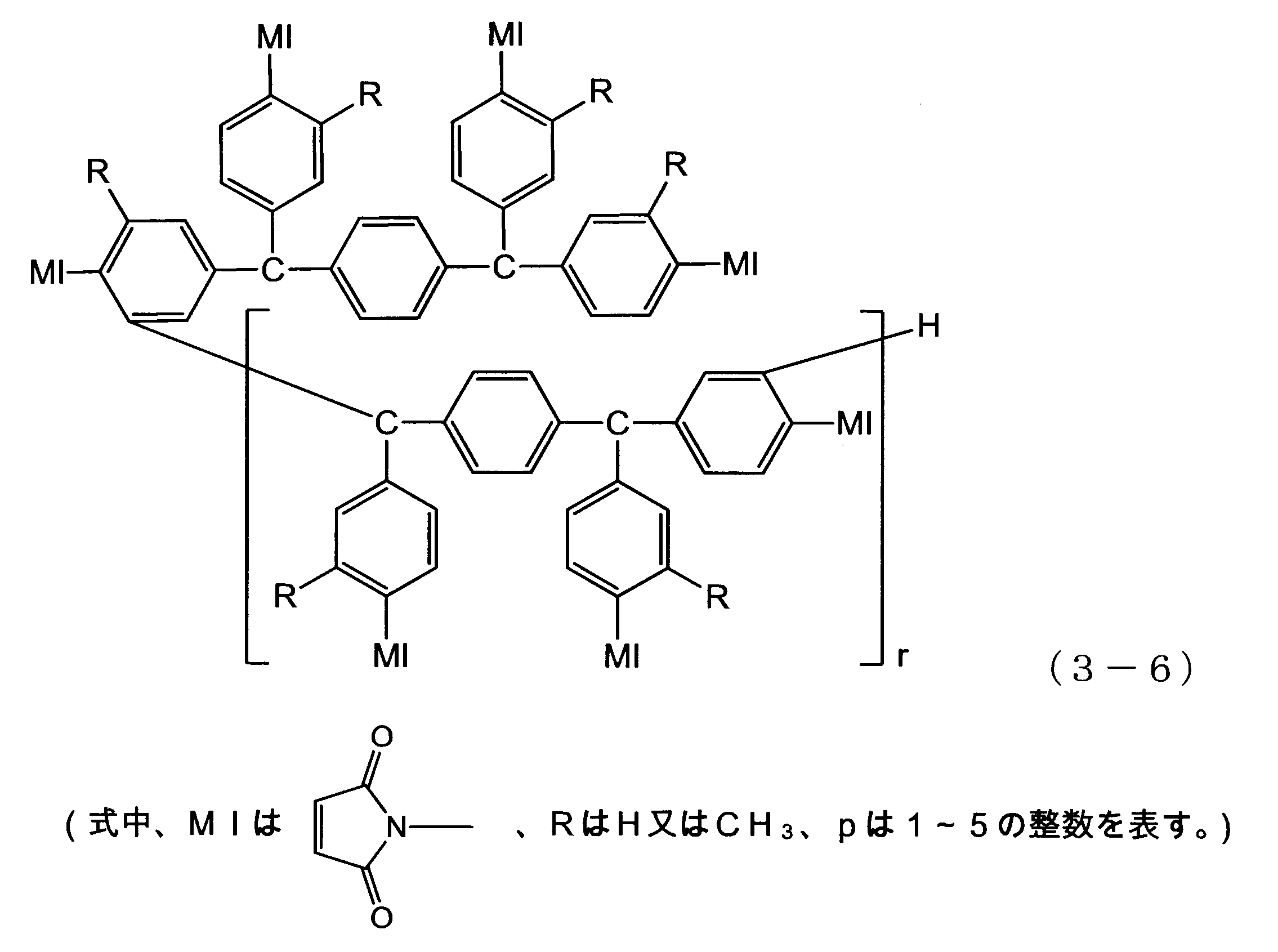
フェノール樹脂は、エポキシ樹脂又はマレイミド樹脂と反応して3次元網状構造を形成する。
フェノール樹脂としては、公知のものが全て使用でき、接着温度、接着剤の硬化温度を低温化でき、また、充分な接着力を得られることから、フェノール成分がp-t-ブチルフェノール、ビスフェノールA、クレゾールからなる群から選ばれる少なくとも1種からなる、p-t-ブチルフェノール型、ビスフェノールA型、クレゾール型、又はそれらの共縮合型のレゾール型フェノール樹脂が好ましい。
フェノール樹脂としては、公知のものが全て使用でき、接着温度、接着剤の硬化温度を低温化でき、また、充分な接着力を得られることから、フェノール成分がp-t-ブチルフェノール、ビスフェノールA、クレゾールからなる群から選ばれる少なくとも1種からなる、p-t-ブチルフェノール型、ビスフェノールA型、クレゾール型、又はそれらの共縮合型のレゾール型フェノール樹脂が好ましい。
熱硬化性接着剤(I)は、必要に応じて、硬化(促進)剤を含有してもよい。「硬化(促進)剤」は、硬化剤又は硬化促進剤を示す。
熱硬化性接着剤(I)において、硬化(促進)剤としては、例えば有機過酸化物、イミダゾール類、リン系触媒(トリフェニルフォスフィン等)、ジアミン化合物等が挙げられる。
有機過酸化物としては、ジアザビシクロオクタン、又はメチルエチルケトンパーオキサイド、シクロヘキサンパーオキサイド、3,3,5-トリメチルシクロヘキサノンパーオキサイド、メチルシクロヘキサノンパーオキサイド、メチルアセトアセテートパーオキサイド、アセチルアセトンパーオキサイド、1,1-ビス(t-ブチルパーオキシ)-3,3,5トリメチルヘキサン、1,1-ビス(t-ブチルパーオキシ)-シクロヘキサン、2,2-ビス(t-ブチルパーオキシ)オクタン、n-ブチル-4,4-ビス(t-ブチルパーオキシ)バレート、2,2-ビス(t-ブチルパーオキシ)ブタン、t-ブチルハイドロパーオキサイド、クメンハイドロパーオキサイド、ジ-イソプロピルベンゼンハイドロパーオキサイド、p-メンタンハイドロパーオキサイド、2,5-ジメチルヘキサン-2,5-ジハイドロパーオキサイド、1,1,3,3-テトラメチルブチルハイドロパーオキサイド、ジ-t-ブチルパーオキサイド、t-ブチルクミルパーオキサイド、ジ-クミルパーオキサイド、α,α’-ビス(t-ブチルパーオキシ-m-イソプロピル)ベンゼン、2,5-ジメチル-2,5-ジ(t-ブチルパーオキシ)ヘキサン、2,5-ジメチル-2,5-ジ(t-ブチルパーオキシ)ヘキシン、アセチルパーオキサイド、イソブチルパーオキサイド、オクタノイルパーオキサイド、デカノイルパーオキサイド、ベンゾイルパーオキサイド、ラウロイルパーオキサイド、3,5,5-トリメチルヘキサノイルパーオキサイド、スクシニックアシッドパーオキサイド、2,4-ジクロロベンゾイルパーオキサイド、m-トルオイルパーオキサイド、ジ-イソプロピルパーオキシジカーボネート、ジ-2-エチルヘキシルパーオキシジカーボネート、ジ-n-プロピルパーオキシジカーボネート、ビス-(4-t-ブチルシクロヘキシル)パーオキシジカーボネート、ジ-ミリスティルパーオキシジカーボネート、ジ-2-エトキシエチルパーオキシジカーボネート、ジ-メトキシイソプロピルパーオキシジカーボネート、ジ(3-メチル-3-メトキシブチル)パーオキシジカーボネート、ジ-アリルパーオキシジカーボネート、t-ブチルパーオキシアセテート、t-ブチルパーオキシイソブチレート、t-ブチルパーオキシピバレート、t-ブチルパーオキシネオデカネート、クミルパーオキシネオデカネート、t-ブチルパーオキシ-2-エチルヘキサネート、t-ブチルパーオキシ-3,5,5-トリメチルヘキサネート、t-ブチルパーオキシラウレート、t-ブチルパーオキシベンゾエート、ジ-t-ブチルパーオキシイソフタレート、2,5-ジメチル-2,5-ジ(ベンゾイルパーオキシ)ヘキサン、t-ブチルパーオキシマレイン酸、t-ブチルパーオキシイソプロピルカーボネート、クミルパーオキシオクテート、t-ヘキシルパーオキシネオデカネート、t-ヘキシルパーオキシピバレート、t-ブチルパーオキシネオヘキサネート、アセチルシクロヘキシルスルフォニルパーオキサイド、t-ブチルパーオキシアリルカーボネート等が挙げられる。
イミダゾール類としては、1,2-ジメチルイミダゾール、1-メチル-2-エチルイミダゾール、2-メチルイミダゾール、2-エチル-4-メチルイミダゾール、2-ウンデシルイミダゾール、2-ヘプタデシルイミダゾール、2-フェニルイミダゾール、1-ベンジル-2-メチルイミダゾール、1-ベンジル-2-フェニルイミダゾール、1-ベンジル-2-フェニルイミダゾール・トリメリット酸塩、1-ベンジル-2-エチルイミダゾール、1-ベンジル-2-エチル-5-メチルイミダゾール、2-エチルイミダゾール、2-イソプロピルイミダゾール、2-フェニル-4-ベンジルイミダゾール、1-シアノエチル-2-メチルイミダゾール、1-シアノエチル-2-エチル-4-メチルイミダゾール、1-シアノエチル-2-ウンデシルイミダゾール、1-シアノエチル-2-イソプロピルイミダゾール、1-シアノエチル-2-フェニルイミダゾール、1-シアノエチル-2-メチルイミダゾリウムトリメリテート、1-シアノエチル-2-フェニルイミダゾリウムトリメリテート、2,4-ジアミノ-6-[2’-メチルイミダゾリル-(1’)]-エチル-s-トリアジン、2,4-ジアミノ-6-[2’-エチル-4-メチルイミダゾリル-(1’)]-エチル-s-トリアジン、2,4-ジアミノ-6-[2’-ウンデシルイミダゾリル-(1’)]-エチル-s-トリアジン、2-メチルイミダゾリウムイソシアヌール酸付加物、2-フェニルイミダゾリウムイソシアヌール酸付加物、2,4-ジアミノ-6-[2’-メチルイミダゾリル-(1’)]-エチル-s-トリアジン-イソシアヌール酸付加物、2-フェニル-4,5-ジヒドロキシメチルイミダゾール、2-フェニル-4-ベンジル-5-ヒドロキシメチルイミダゾール、4,4’-メチレン-ビス-(2-エチル-5-メチルイミダゾール)、1-アミノエチル-2-メチルイミダゾール、1-シアノエチル-2-フェニル-4,5-ジ(シアノエトキシメチル)イミダゾール、1-ドデシル-2-メチル-3-ベンジルイミダゾリウムクロライド、2-メチルイミダゾール・ベンゾトリアゾール付加物、1-アミノエチル-2-エチルイミダゾール、1-(シアノエチルアミノエチル)-2-メチルイミダゾール、N,N’-[2-メチルイミダゾリル-(1)-エチル]-アジポイルジアミド、N,N’-ビス-(2-メチルイミダゾリル-1-エチル)尿素、N-(2-メチルイミダゾリル-1-エチル)尿素、N,N’-[2-メチルイミダゾリル-(1)-エチル]ドデカンジオイルジアミド、N,N’-[2-メチルイミダゾリル-(1)-エチル]エイコサンジオイルジアミド、1-ベンジル-2-フェニルイミダゾール・塩化水素酸塩等が挙げられる。
熱硬化性接着剤(I)において、硬化(促進)剤としては、例えば有機過酸化物、イミダゾール類、リン系触媒(トリフェニルフォスフィン等)、ジアミン化合物等が挙げられる。
有機過酸化物としては、ジアザビシクロオクタン、又はメチルエチルケトンパーオキサイド、シクロヘキサンパーオキサイド、3,3,5-トリメチルシクロヘキサノンパーオキサイド、メチルシクロヘキサノンパーオキサイド、メチルアセトアセテートパーオキサイド、アセチルアセトンパーオキサイド、1,1-ビス(t-ブチルパーオキシ)-3,3,5トリメチルヘキサン、1,1-ビス(t-ブチルパーオキシ)-シクロヘキサン、2,2-ビス(t-ブチルパーオキシ)オクタン、n-ブチル-4,4-ビス(t-ブチルパーオキシ)バレート、2,2-ビス(t-ブチルパーオキシ)ブタン、t-ブチルハイドロパーオキサイド、クメンハイドロパーオキサイド、ジ-イソプロピルベンゼンハイドロパーオキサイド、p-メンタンハイドロパーオキサイド、2,5-ジメチルヘキサン-2,5-ジハイドロパーオキサイド、1,1,3,3-テトラメチルブチルハイドロパーオキサイド、ジ-t-ブチルパーオキサイド、t-ブチルクミルパーオキサイド、ジ-クミルパーオキサイド、α,α’-ビス(t-ブチルパーオキシ-m-イソプロピル)ベンゼン、2,5-ジメチル-2,5-ジ(t-ブチルパーオキシ)ヘキサン、2,5-ジメチル-2,5-ジ(t-ブチルパーオキシ)ヘキシン、アセチルパーオキサイド、イソブチルパーオキサイド、オクタノイルパーオキサイド、デカノイルパーオキサイド、ベンゾイルパーオキサイド、ラウロイルパーオキサイド、3,5,5-トリメチルヘキサノイルパーオキサイド、スクシニックアシッドパーオキサイド、2,4-ジクロロベンゾイルパーオキサイド、m-トルオイルパーオキサイド、ジ-イソプロピルパーオキシジカーボネート、ジ-2-エチルヘキシルパーオキシジカーボネート、ジ-n-プロピルパーオキシジカーボネート、ビス-(4-t-ブチルシクロヘキシル)パーオキシジカーボネート、ジ-ミリスティルパーオキシジカーボネート、ジ-2-エトキシエチルパーオキシジカーボネート、ジ-メトキシイソプロピルパーオキシジカーボネート、ジ(3-メチル-3-メトキシブチル)パーオキシジカーボネート、ジ-アリルパーオキシジカーボネート、t-ブチルパーオキシアセテート、t-ブチルパーオキシイソブチレート、t-ブチルパーオキシピバレート、t-ブチルパーオキシネオデカネート、クミルパーオキシネオデカネート、t-ブチルパーオキシ-2-エチルヘキサネート、t-ブチルパーオキシ-3,5,5-トリメチルヘキサネート、t-ブチルパーオキシラウレート、t-ブチルパーオキシベンゾエート、ジ-t-ブチルパーオキシイソフタレート、2,5-ジメチル-2,5-ジ(ベンゾイルパーオキシ)ヘキサン、t-ブチルパーオキシマレイン酸、t-ブチルパーオキシイソプロピルカーボネート、クミルパーオキシオクテート、t-ヘキシルパーオキシネオデカネート、t-ヘキシルパーオキシピバレート、t-ブチルパーオキシネオヘキサネート、アセチルシクロヘキシルスルフォニルパーオキサイド、t-ブチルパーオキシアリルカーボネート等が挙げられる。
イミダゾール類としては、1,2-ジメチルイミダゾール、1-メチル-2-エチルイミダゾール、2-メチルイミダゾール、2-エチル-4-メチルイミダゾール、2-ウンデシルイミダゾール、2-ヘプタデシルイミダゾール、2-フェニルイミダゾール、1-ベンジル-2-メチルイミダゾール、1-ベンジル-2-フェニルイミダゾール、1-ベンジル-2-フェニルイミダゾール・トリメリット酸塩、1-ベンジル-2-エチルイミダゾール、1-ベンジル-2-エチル-5-メチルイミダゾール、2-エチルイミダゾール、2-イソプロピルイミダゾール、2-フェニル-4-ベンジルイミダゾール、1-シアノエチル-2-メチルイミダゾール、1-シアノエチル-2-エチル-4-メチルイミダゾール、1-シアノエチル-2-ウンデシルイミダゾール、1-シアノエチル-2-イソプロピルイミダゾール、1-シアノエチル-2-フェニルイミダゾール、1-シアノエチル-2-メチルイミダゾリウムトリメリテート、1-シアノエチル-2-フェニルイミダゾリウムトリメリテート、2,4-ジアミノ-6-[2’-メチルイミダゾリル-(1’)]-エチル-s-トリアジン、2,4-ジアミノ-6-[2’-エチル-4-メチルイミダゾリル-(1’)]-エチル-s-トリアジン、2,4-ジアミノ-6-[2’-ウンデシルイミダゾリル-(1’)]-エチル-s-トリアジン、2-メチルイミダゾリウムイソシアヌール酸付加物、2-フェニルイミダゾリウムイソシアヌール酸付加物、2,4-ジアミノ-6-[2’-メチルイミダゾリル-(1’)]-エチル-s-トリアジン-イソシアヌール酸付加物、2-フェニル-4,5-ジヒドロキシメチルイミダゾール、2-フェニル-4-ベンジル-5-ヒドロキシメチルイミダゾール、4,4’-メチレン-ビス-(2-エチル-5-メチルイミダゾール)、1-アミノエチル-2-メチルイミダゾール、1-シアノエチル-2-フェニル-4,5-ジ(シアノエトキシメチル)イミダゾール、1-ドデシル-2-メチル-3-ベンジルイミダゾリウムクロライド、2-メチルイミダゾール・ベンゾトリアゾール付加物、1-アミノエチル-2-エチルイミダゾール、1-(シアノエチルアミノエチル)-2-メチルイミダゾール、N,N’-[2-メチルイミダゾリル-(1)-エチル]-アジポイルジアミド、N,N’-ビス-(2-メチルイミダゾリル-1-エチル)尿素、N-(2-メチルイミダゾリル-1-エチル)尿素、N,N’-[2-メチルイミダゾリル-(1)-エチル]ドデカンジオイルジアミド、N,N’-[2-メチルイミダゾリル-(1)-エチル]エイコサンジオイルジアミド、1-ベンジル-2-フェニルイミダゾール・塩化水素酸塩等が挙げられる。
ジアミン化合物は、エポキシ樹脂やマレイミド樹脂と反応・硬化し、接着層の耐熱性を向上させる効果がある。
ジアミン化合物としては、例えば下記式(5-1)で表される化合物等が挙げられる。
H2N-R2-NH2 ・・・(5-1)
(式中、R2は2価の脂肪族基、芳香族基又は脂環式基を表す。)
ジアミン化合物としては、例えば下記式(5-1)で表される化合物等が挙げられる。
H2N-R2-NH2 ・・・(5-1)
(式中、R2は2価の脂肪族基、芳香族基又は脂環式基を表す。)
R2は前記R1と同様である。
式(5-1)で表される化合物の具体例としては、3,3’-ジアミノビフェニル、3,4’-ジアミノビフェニル、4,4’-ジアミノビフェニル、3,3’-ジアミノジフェニルメタン、3,4’-ジアミノジフェニルメタン、4,4’-ジアミノジフェニルメタン、2,2-(3,3’-ジアミノジフェニル)プロパン、2,2-(3,4’-ジアミノジフェニル)プロパン、2,2-(4,4’-ジアミノジフェニル)プロパン、2,2-(3,3’-ジアミノジフェニル)ヘキサフルオロプロパン、2,2-(3,4’-ジアミノジフェニル)ヘキサフルオロプロパン、2,2-(4,4’-ジアミノジフェニル)ヘキサフルオロプロパン、3,3’-オキシジアニリン、3,4’-オキシジアニリン、4,4’-オキシジアニリン、3,3’-ジアミノジフェニルスルフィド、3,4’-ジアミノジフェニルスルフィド、4,4’-ジアミノジフェニルスルフィド、3,3’-ジアミノジフェニルスルホン、3,4’-ジアミノジフェニルスルホン、4,4’-ジアミノジフェニルスルホン、1,3-ビス[1-(3-アミノフェニル)-1-メチルエチル]ベンゼン、1,3-ビス[1-(4-アミノフェニル)-1-メチルエチル]ベンゼン、1,4-ビス[1-(3-アミノフェニル)ベンゼン、1,3-ビス(3-アミノフェノキシ)ベンゼン、1,3-ビス(4-アミノフェノキシ)ベンゼン、1,4-ビス(3-アミノフェノキシ)ベンゼン、1,4-ビス(4-アミノフェノキシ)ベンゼン、3,3’-ビス(3-アミノフェノキシ)ジフェニルエーテル、3,3’-ビス(4-アミノフェノキシ)ジフェニルエーテル、3,4’-ビス(3-アミノフェノキシ)ジフェニルエーテル、3,4’-ビス(4-アミノフェノキシ)ジフェニルエーテル、4,4’-ビス(3-アミノフェノキシ)ジフェニルエーテル、4,4’-ビス(4-アミノフェノキシ)ジフェニルエーテル、1,4-ビス[1-(4-アミノフェニル)-1-メチルエチル-ビス(3-アミノフェノキシ)ビフェニル、3,3’-ビス(4-アミノフェノキシ)ビフェニル、3,4’-ビス(3-アミノフェノキシ)ビフェニル、3,4’-ビス(4-アミノフェノキシ)ビフェニル、4,4’-ビス(3-アミノフェノキシ)ビフェニル、4,4’-ビス(4-アミノフェノキシ)ビフェニル、ビス[4-(3-アミノフェノキシ)フェニル]スルホン、ビス[4-(4-アミノフェノキシ)フェニル]スルホン、2,2-ビス[3-(3-アミノフェノキシ)フェニル]プロパン、2,2-ビス[3-(4-アミノフェノキシ)フェニル]プロパン、2,2-ビス[4-(3-アミノフェノキシ)フェニル]プロパン、2,2-ビス[4-(4-アミノフェノキシ)フェニル]プロパン、2,2-ビス[3-(3-アミノフェノキシ)フェニル]ヘキサフルオロプロパン、2,2-ビス[3-(4-アミノフェノキシ)フェニル]ヘキサフルオロプロパン、2,2-ビス[4-(3-アミノフェノキシ)フェニル]ヘキサフルオロプロパン、2,2-ビス[4-(4-アミノフェノキシ)フェニル]ヘキサフルオロプロパン、9,9-ビス(3-アミノフェニル)フルオレン、9,9-ビス(4-アミノフェニル)フルオレン等が挙げられる。
式(5-1)で表される化合物の具体例としては、3,3’-ジアミノビフェニル、3,4’-ジアミノビフェニル、4,4’-ジアミノビフェニル、3,3’-ジアミノジフェニルメタン、3,4’-ジアミノジフェニルメタン、4,4’-ジアミノジフェニルメタン、2,2-(3,3’-ジアミノジフェニル)プロパン、2,2-(3,4’-ジアミノジフェニル)プロパン、2,2-(4,4’-ジアミノジフェニル)プロパン、2,2-(3,3’-ジアミノジフェニル)ヘキサフルオロプロパン、2,2-(3,4’-ジアミノジフェニル)ヘキサフルオロプロパン、2,2-(4,4’-ジアミノジフェニル)ヘキサフルオロプロパン、3,3’-オキシジアニリン、3,4’-オキシジアニリン、4,4’-オキシジアニリン、3,3’-ジアミノジフェニルスルフィド、3,4’-ジアミノジフェニルスルフィド、4,4’-ジアミノジフェニルスルフィド、3,3’-ジアミノジフェニルスルホン、3,4’-ジアミノジフェニルスルホン、4,4’-ジアミノジフェニルスルホン、1,3-ビス[1-(3-アミノフェニル)-1-メチルエチル]ベンゼン、1,3-ビス[1-(4-アミノフェニル)-1-メチルエチル]ベンゼン、1,4-ビス[1-(3-アミノフェニル)ベンゼン、1,3-ビス(3-アミノフェノキシ)ベンゼン、1,3-ビス(4-アミノフェノキシ)ベンゼン、1,4-ビス(3-アミノフェノキシ)ベンゼン、1,4-ビス(4-アミノフェノキシ)ベンゼン、3,3’-ビス(3-アミノフェノキシ)ジフェニルエーテル、3,3’-ビス(4-アミノフェノキシ)ジフェニルエーテル、3,4’-ビス(3-アミノフェノキシ)ジフェニルエーテル、3,4’-ビス(4-アミノフェノキシ)ジフェニルエーテル、4,4’-ビス(3-アミノフェノキシ)ジフェニルエーテル、4,4’-ビス(4-アミノフェノキシ)ジフェニルエーテル、1,4-ビス[1-(4-アミノフェニル)-1-メチルエチル-ビス(3-アミノフェノキシ)ビフェニル、3,3’-ビス(4-アミノフェノキシ)ビフェニル、3,4’-ビス(3-アミノフェノキシ)ビフェニル、3,4’-ビス(4-アミノフェノキシ)ビフェニル、4,4’-ビス(3-アミノフェノキシ)ビフェニル、4,4’-ビス(4-アミノフェノキシ)ビフェニル、ビス[4-(3-アミノフェノキシ)フェニル]スルホン、ビス[4-(4-アミノフェノキシ)フェニル]スルホン、2,2-ビス[3-(3-アミノフェノキシ)フェニル]プロパン、2,2-ビス[3-(4-アミノフェノキシ)フェニル]プロパン、2,2-ビス[4-(3-アミノフェノキシ)フェニル]プロパン、2,2-ビス[4-(4-アミノフェノキシ)フェニル]プロパン、2,2-ビス[3-(3-アミノフェノキシ)フェニル]ヘキサフルオロプロパン、2,2-ビス[3-(4-アミノフェノキシ)フェニル]ヘキサフルオロプロパン、2,2-ビス[4-(3-アミノフェノキシ)フェニル]ヘキサフルオロプロパン、2,2-ビス[4-(4-アミノフェノキシ)フェニル]ヘキサフルオロプロパン、9,9-ビス(3-アミノフェニル)フルオレン、9,9-ビス(4-アミノフェニル)フルオレン等が挙げられる。
マレイミド樹脂を使用する場合、ジアミン化合物としては、両末端にアミノ基を有するシロキサン化合物が好ましく、例えば下記式(4-1)又は(4-2)で表される化合物等が挙げられる。
H2N-R1-Si(CH3)2-O-(Si(CH3)2-O)n-Si(CH3)2-R1-NH2 ・・・(4-1)
H2N-R1-(Si(CH3)2-O)m-(Si(Ph)2-O)n-Si(CH3)2-R1-NH2 ・・・(4-2)
(式中、R1は2価の脂肪族基、芳香族基又は脂環式基を表し、Phはフェニル基を表し、m及びnはそれぞれ0~10の整数を表す。)
H2N-R1-Si(CH3)2-O-(Si(CH3)2-O)n-Si(CH3)2-R1-NH2 ・・・(4-1)
H2N-R1-(Si(CH3)2-O)m-(Si(Ph)2-O)n-Si(CH3)2-R1-NH2 ・・・(4-2)
(式中、R1は2価の脂肪族基、芳香族基又は脂環式基を表し、Phはフェニル基を表し、m及びnはそれぞれ0~10の整数を表す。)
R1における2価の脂肪族基としては、例えばアルキレン基、等が挙げられる。アルキレン基の炭素数は、1~10が好ましく、1~7がより好ましい。
式(4-1)又は(4-2)で表される化合物の具体例としては、ビス(3-アミノプロピル)テトラメチルジシロキサン、アミノプロピル末端のジメチルシロキサン4量体、8量体、ビス(3-アミノフェノキシメチル)テトラメチルジシロキサン等が挙げられる。
式(4-1)又は(4-2)で表される化合物の具体例としては、ビス(3-アミノプロピル)テトラメチルジシロキサン、アミノプロピル末端のジメチルシロキサン4量体、8量体、ビス(3-アミノフェノキシメチル)テトラメチルジシロキサン等が挙げられる。
熱硬化性接着剤(I)は、必要に応じて、架橋剤、添加剤、改質剤、加工助剤、フィラー等を含有してもよい。
架橋剤としては、前記有機化酸化物等が挙げられる。
添加剤としては、耐熱性向上の為の酸化防止剤、難燃性付与する為の難燃剤、帯電防止剤などが上げられる。
酸化防止剤としては、チバ・スペシャリティ・ケミカルズ社製 IRGANOX1010、IRGANOX1076等が挙げられ、難燃剤としては、水酸化アルミニウムの様な無機充填剤タイプの物や、ADEKA製 アデカスタブFP‐600などのようなリン酸エステル系などが挙げられる。
フィラーとしては、有機充填材、無機充填材等が挙げられる。これらはいずれか一方を用いてもよく、併用してもよい。有機充填材、無機充填材はそれぞれ、公知のものを使用できる。例えば、アルミナ、窒化ケイ素、窒素化ホウ素等は、絶縁性および熱伝導性の付与の目的で、銀、銅、ニッケル等の金属粉末は、熱伝導性の付与の目的で、また、酸化チタン、炭酸カルシウム、シリカ、酸化亜鉛、酸化マグネシウム等は、誘電特性、熱膨張率、粘弾性、タック性の調整の目的で含有させることができる。
架橋剤としては、前記有機化酸化物等が挙げられる。
添加剤としては、耐熱性向上の為の酸化防止剤、難燃性付与する為の難燃剤、帯電防止剤などが上げられる。
酸化防止剤としては、チバ・スペシャリティ・ケミカルズ社製 IRGANOX1010、IRGANOX1076等が挙げられ、難燃剤としては、水酸化アルミニウムの様な無機充填剤タイプの物や、ADEKA製 アデカスタブFP‐600などのようなリン酸エステル系などが挙げられる。
フィラーとしては、有機充填材、無機充填材等が挙げられる。これらはいずれか一方を用いてもよく、併用してもよい。有機充填材、無機充填材はそれぞれ、公知のものを使用できる。例えば、アルミナ、窒化ケイ素、窒素化ホウ素等は、絶縁性および熱伝導性の付与の目的で、銀、銅、ニッケル等の金属粉末は、熱伝導性の付与の目的で、また、酸化チタン、炭酸カルシウム、シリカ、酸化亜鉛、酸化マグネシウム等は、誘電特性、熱膨張率、粘弾性、タック性の調整の目的で含有させることができる。
熱硬化性接着剤(I)においては、アクリロニトリル-ブタジエン共重合体100質量部に対して、エポキシ樹脂又はマレイミド樹脂とフェノール樹脂との総和が40~700質量部であることが好ましく、100~500質量部であることがより好ましい。エポキシ樹脂又はマレイミド樹脂とフェノール樹脂との総和が上記範囲の下限値以上であると、硬化後の弾性率が高くなり、耐熱性やワイヤボンド性が良好であり、上記範囲の上限値以下であると、Bステージでの膜が脆くなり難く、作業性や加工性が良好である。
前記エポキシ樹脂と、フェノール樹脂との比率は、官能基当量比で1:3~1:0.1が好ましく、1:1.5~1:0.3がより好ましい。フェノール樹脂の比率が少なすぎると硬化物が脆くなりやすく、接着力が低下しやすい、フェノール樹脂の比率が大きすぎると硬化後の弾性率が低くなり易く、耐熱性やワイヤボンド性が低下しやすい。
前記マレイミド樹脂と、フェノール樹脂との比率は、官能基当量比で1:2~1:0.1が好ましく、1:1.5~1:0.3がより好ましい。フェノール樹脂の比率が少なすぎると硬化物が脆くなりやすく、接着力が低下しやすい、フェノール樹脂の比率が大きすぎると硬化後の弾性率が低くなり易く、耐熱性やワイヤボンド性が低下しやすい。
マレイミド樹脂を使用する場合、架橋剤としてジアミン化合物を用いる事が好ましい。
ジアミン化合物の含有量は、前記マレイミド樹脂の官能基等量比で0.01~2モル等量以下が好ましい。ジアミン化合物の含有量が上記下限値以上であれば、接着層の強度が良好でテープとしての加工性が良く、また、絶縁層5との密着性も良好であり、上記上限値以下であれば、接着層を塗料にした際、塗料中にゲルを生じずに塗料を調製する事が可能となる。
ジアミン化合物の含有量は、前記マレイミド樹脂の官能基等量比で0.01~2モル等量以下が好ましい。ジアミン化合物の含有量が上記下限値以上であれば、接着層の強度が良好でテープとしての加工性が良く、また、絶縁層5との密着性も良好であり、上記上限値以下であれば、接着層を塗料にした際、塗料中にゲルを生じずに塗料を調製する事が可能となる。
熱硬化性接着剤(I)がフィラーを含有する場合、フィラーの含有量は、熱硬化性接着剤の全固形分に対して1~70質量%が好ましく、5~50質量%がより好ましい。フィラーの含有量が、70質量%超えると、接着テープとしての加工性等が悪くなるおそれがある。
熱硬化性接着剤(II)における熱可塑性ポリイミド樹脂としては、熱可塑性接着剤で挙げたものと同様のものが挙げられる。
エポキシ樹脂、フェノール樹脂はそれぞれ、熱硬化性接着剤(I)で挙げたものと同様のものが挙げられる。
エポキシ樹脂、フェノール樹脂はそれぞれ、熱硬化性接着剤(I)で挙げたものと同様のものが挙げられる。
熱硬化性接着剤(II)は、必要に応じて、硬化(促進)剤、架橋剤、添加剤、改質剤、加工助剤、フィラー等を含有してもよい。
熱硬化性接着剤(II)において、硬化(促進)剤としては、例えばイミダゾール類、リン系触媒(トリフェニルフォスフィン等)、アミン系触媒(1,8-ジアザビシクロ(5,4,0)ウンデセン等)等が挙げられる。イミダゾール類としては熱硬化性接着剤(I)で挙げたものと同様のものが挙げられる。
架橋剤、添加剤、改質剤、加工助剤、フィラーはそれぞれ熱硬化性接着剤(I)で挙げたものと同様のものが挙げられる。
架橋剤、添加剤、改質剤、加工助剤、フィラーはそれぞれ熱硬化性接着剤(I)で挙げたものと同様のものが挙げられる。
熱硬化性接着剤(II)においては、熱可塑性ポリイミド樹脂100質量部に対して、エポキシ樹脂とフェノール樹脂との総和が0.1~300質量部であることが好ましく、0.5~200質量部であることがより好ましい。エポキシ樹脂とフェノール樹脂との総和が上記範囲の下限値以上であると、接着剤が硬化した後の貯蔵弾性率が高くなり、耐熱性やワイヤボンド性が良好であり、上記範囲の上限値以下であると、接着剤のBステージやCステージにおける機械的強度が損なわれず、膜が脆く無く、加工性や作業性が良好である。
前記エポキシ樹脂とフェノール樹脂との比率は、官能基当量比で1:1.5~1:0.1が好ましく、1:1.1~1:0.3がより好ましい。フェノール樹脂の比率が少なすぎると硬化物が脆くなりやすく、接着力が低下しやすい、フェノール樹脂の比率が大きすぎると耐熱性が低下する。
所望により、エポキシ樹脂用の硬化剤および硬化促進剤を含有させることができる。例えば、イミダゾール類、第3アミン類、フェノール類、ジシアンジアミド類、芳香族ジアミン類、有機過酸化物等をあげることができる。
熱硬化性接着剤(II)がフィラーを含有する場合、フィラーの含有量は、熱硬化性接着剤の全固形分に対して4~40質量%が好ましく、9~24質量%がより好ましい。フィラーの含有量が前記範囲の下限値以上であれば、テーピング特性の安定化効果が充分に発揮され、40質量%以下であれば、接着層の接着強度、接着テープの加工性等が良好である。
熱硬化性接着剤(I)又は(II)は、通常、上記の各成分と有機溶剤等の液状媒体とを含む液状の熱硬化性接着剤として用いられる。例えば、このような液状の熱硬化性接着剤を絶縁層5又は金属層1に塗布し、乾燥することで、第一の接着層3が形成される。このとき、第一の接着層3は、半硬化状態とされてもよい。半硬化状態のコントロール方法は限定しないが、エージング等でコントロールすることが好ましい。
液状媒体としては、例えば、N-メチル-2-ピロリドン、N,N-ジメチルアセトアミド、N,N-ジメチルホルムアミド、ジメチルスルホキシド、スルホラン、ヘキサメチルリン酸トリアミド、1,3-ジメチル-2-イミダゾリドン、ヘキサン、ベンゼン、トルエン、キシレン、メチルエチルケトン、アセトン、ジエチルエーテル、テトラヒドロフラン、ジオキサン、1,2-ジメトキシエタン、ジエチレングリコールジメチルエーテル、メチルセロソルブ、セロソルブアセテート、メタノール、エタノール、プロパノール、イソプロパノール、酢酸メチル、酢酸エチル、アセトニトリル、塩化メチレン、クロロホルム、四塩化炭素、クロロベンゼン、ジクロロベンゼン、ジクロロエタン、トリクロロエタン等が挙げられる。
液状媒体としては、例えば、N-メチル-2-ピロリドン、N,N-ジメチルアセトアミド、N,N-ジメチルホルムアミド、ジメチルスルホキシド、スルホラン、ヘキサメチルリン酸トリアミド、1,3-ジメチル-2-イミダゾリドン、ヘキサン、ベンゼン、トルエン、キシレン、メチルエチルケトン、アセトン、ジエチルエーテル、テトラヒドロフラン、ジオキサン、1,2-ジメトキシエタン、ジエチレングリコールジメチルエーテル、メチルセロソルブ、セロソルブアセテート、メタノール、エタノール、プロパノール、イソプロパノール、酢酸メチル、酢酸エチル、アセトニトリル、塩化メチレン、クロロホルム、四塩化炭素、クロロベンゼン、ジクロロベンゼン、ジクロロエタン、トリクロロエタン等が挙げられる。
第一の接着層3の厚みは、1~50μmが好ましく、5~35μmがより好ましい。第一の接着層3の厚みが上記下限値以上であれば、金属層1との接着性が良好であり、上記上限値以下であれば、ワイヤボンド性が良好である。第一の接着層3の厚みを厚くしすぎる事で、ワイヤボンド性が低下するおそれがある。
(絶縁層)
絶縁層5の材質としては、特に限定されず、例えばポリイミド、ポリアミド、ポリエーテルエーテルケトン、ポリエーテルスルフォン、ポリフェニレンサルファイド、ポリエーテル樹脂、ポリアリレート、ポリパラバン酸、ポリエチレンテレフタレート、ポリエチレンナフタレート等の耐熱性樹脂のフィルム;エポキシ樹脂-ガラスクロス、エポキシ樹脂-ポリイミド-ガラスクロス等の複合耐熱フィルム;紙、織布、不織布等が挙げられる。
絶縁層5としては、耐熱性、絶縁性、加工性の観点から、非熱可塑性ポリイミドフィルムが好ましい。
絶縁層5の材質としては、特に限定されず、例えばポリイミド、ポリアミド、ポリエーテルエーテルケトン、ポリエーテルスルフォン、ポリフェニレンサルファイド、ポリエーテル樹脂、ポリアリレート、ポリパラバン酸、ポリエチレンテレフタレート、ポリエチレンナフタレート等の耐熱性樹脂のフィルム;エポキシ樹脂-ガラスクロス、エポキシ樹脂-ポリイミド-ガラスクロス等の複合耐熱フィルム;紙、織布、不織布等が挙げられる。
絶縁層5としては、耐熱性、絶縁性、加工性の観点から、非熱可塑性ポリイミドフィルムが好ましい。
絶縁層5の厚みは、5μm以上が好ましく、7~125μmがより好ましく、10~75μmがさらに好ましい。絶縁層5の厚みが上記下限値以上であると、接着テープに打ち抜き等の加工を施した後でも、金属層と被着体(リードフレーム等)との間の絶縁性を確保しやすい。また、接着テープ10が充分なコシを有し、扱いやすい。絶縁層5の厚みが上記上限値以下であると、打ち抜き等の加工をしやすい。
絶縁層5の引張弾性率は100~700MPaであることが好ましい。引張弾性率が前記範囲内にあると、接着テープに充分なコシが得られ、接着テープ作成時(金属層1との積層や接着剤の塗布など)の作業性が良好となり、リードフレーム等の被着体への貼り付け加工性も良好となる。
絶縁層5の線膨張係数(50~200℃)(MD)は、1×10⁻⁶/℃~40×10-6/℃であることが好ましく、3×10-6/℃~30×10-6/℃がより好ましい。リードフレームは一般的に銅製である。絶縁層5の線膨張係数が前記範囲内にあると、被着体である銅との線膨張係数が近くなり、加熱による歪が発生しにくくなり、リードフレームやパッケージの加工性が良好となる。金属層1として、アルミニウムやアルミニウム合金を使用する場合は、さらに線膨張係数が小さいものを使用することが好ましい。
絶縁層5の線膨張係数(50~200℃)(MD)は、1×10⁻⁶/℃~40×10-6/℃であることが好ましく、3×10-6/℃~30×10-6/℃がより好ましい。リードフレームは一般的に銅製である。絶縁層5の線膨張係数が前記範囲内にあると、被着体である銅との線膨張係数が近くなり、加熱による歪が発生しにくくなり、リードフレームやパッケージの加工性が良好となる。金属層1として、アルミニウムやアルミニウム合金を使用する場合は、さらに線膨張係数が小さいものを使用することが好ましい。
(第二の接着層)
第二の接着層7は、接着テープ10の使用時において被着体(リードフレーム等)と貼り合わされる層であり、金属層側とは反対側の最外層に配置されている。
第二の接着層7は、接着剤から形成される。第二の接着層7を形成する接着剤としては、公知の接着剤から適宜選択して用いることができる。
接着剤としては、熱可塑性接着剤、熱硬化性接着剤等が挙げられる。第二の接着層7は、熱可塑性接着剤から形成された層であってもよく、熱硬化性接着剤から形成された層であってもよい。
熱可塑性接着剤、熱硬化性接着剤はそれぞれ、第一の接着層3の項で挙げたものと同様のものが挙げられる。
他に熱可塑性接着剤としては、カルボン酸無水物(テトラカルボン酸無水物、トリカルボン酸無水物、ジカルボン酸無水物)とジアミン及びジイソシアネートより得られるポリアミドイミド樹脂;カルボン酸無水物(テトラカルボン酸無水物、トリカルボン酸無水物、ジカルボン酸無水物)とジアミン又はジイソシアネートとポリエーテルによって得られるポリエーテルイミド樹脂;カルボン酸無水物(テトラカルボン酸無水物、トリカルボン酸無水物、ジカルボン酸無水物)とジアミン又はジイソシアネートとポリエステルによって得られるポリエステルイミド樹脂;カルボン酸無水物(テトラカルボン酸無水物、トリカルボン酸無水物、ジカルボン酸無水物)とジアミン又はジイソシアネートと(式)HOOC-R-COOH(R:水素添加型ポリブタジエン基、水素添加型ポリイソプレン基、又はポリイソブチレン基)を反応させて得られる共重合組成物等を例示できる。
また、熱硬化性接着剤としては他に、前記熱可塑性接着剤に例示される熱可塑性樹脂と、エポキシ樹脂やフェノール樹脂等の熱硬化性樹脂成分を含む組成物;ポリエステル樹脂と、エポキシ樹脂やフェノール樹脂を含む組成物;ポリアミド樹脂と、エポキシ樹脂やフェノール樹脂を含む組成物;カルボキシル基含有アクリロニトリル-ブタジエン共重合体と、エポキシ樹脂、マレイミド樹脂、エポキシ樹脂硬化剤及びシリコーン化合物を含む組成物;カルボキシル基含有アクリロニトリル-ブタジエン共重合体、エポキシ樹脂、フェノール樹脂、アミン又は酸無水物を硬化剤とする成分を含む組成物;等も挙げられる。
ただし、第二の接着層7の175℃1時間の加熱処理後の貯蔵弾性率は、1×10⁶Pa以上である必要はなく、1×10⁶Pa未満であってもよい。
一方で、接着テープ10は、リードフレームメーカーや基板メーカーでリードフレーム上や基板上にテーピングされたり、半導体メーカーにて貼着けされた後に、ICを搭載し、樹脂封止され、半導体装置として使用される。その際、接着テープ10が半導体装置の配線上に直に設置される事がある。そのため接着テープ10の第二の接着層7は、半導体レベルとしての電気的信頼性およびテーピング時の作業性を有することが好ましい。
なお、電気的信頼性とは、後述するマイグレーション試験(85℃85%RH、5V印加、96時間)の条件下において、電流のリーク、ショートを起こさないということを意味する。
第二の接着層7は、接着テープ10の使用時において被着体(リードフレーム等)と貼り合わされる層であり、金属層側とは反対側の最外層に配置されている。
第二の接着層7は、接着剤から形成される。第二の接着層7を形成する接着剤としては、公知の接着剤から適宜選択して用いることができる。
接着剤としては、熱可塑性接着剤、熱硬化性接着剤等が挙げられる。第二の接着層7は、熱可塑性接着剤から形成された層であってもよく、熱硬化性接着剤から形成された層であってもよい。
熱可塑性接着剤、熱硬化性接着剤はそれぞれ、第一の接着層3の項で挙げたものと同様のものが挙げられる。
他に熱可塑性接着剤としては、カルボン酸無水物(テトラカルボン酸無水物、トリカルボン酸無水物、ジカルボン酸無水物)とジアミン及びジイソシアネートより得られるポリアミドイミド樹脂;カルボン酸無水物(テトラカルボン酸無水物、トリカルボン酸無水物、ジカルボン酸無水物)とジアミン又はジイソシアネートとポリエーテルによって得られるポリエーテルイミド樹脂;カルボン酸無水物(テトラカルボン酸無水物、トリカルボン酸無水物、ジカルボン酸無水物)とジアミン又はジイソシアネートとポリエステルによって得られるポリエステルイミド樹脂;カルボン酸無水物(テトラカルボン酸無水物、トリカルボン酸無水物、ジカルボン酸無水物)とジアミン又はジイソシアネートと(式)HOOC-R-COOH(R:水素添加型ポリブタジエン基、水素添加型ポリイソプレン基、又はポリイソブチレン基)を反応させて得られる共重合組成物等を例示できる。
また、熱硬化性接着剤としては他に、前記熱可塑性接着剤に例示される熱可塑性樹脂と、エポキシ樹脂やフェノール樹脂等の熱硬化性樹脂成分を含む組成物;ポリエステル樹脂と、エポキシ樹脂やフェノール樹脂を含む組成物;ポリアミド樹脂と、エポキシ樹脂やフェノール樹脂を含む組成物;カルボキシル基含有アクリロニトリル-ブタジエン共重合体と、エポキシ樹脂、マレイミド樹脂、エポキシ樹脂硬化剤及びシリコーン化合物を含む組成物;カルボキシル基含有アクリロニトリル-ブタジエン共重合体、エポキシ樹脂、フェノール樹脂、アミン又は酸無水物を硬化剤とする成分を含む組成物;等も挙げられる。
ただし、第二の接着層7の175℃1時間の加熱処理後の貯蔵弾性率は、1×10⁶Pa以上である必要はなく、1×10⁶Pa未満であってもよい。
一方で、接着テープ10は、リードフレームメーカーや基板メーカーでリードフレーム上や基板上にテーピングされたり、半導体メーカーにて貼着けされた後に、ICを搭載し、樹脂封止され、半導体装置として使用される。その際、接着テープ10が半導体装置の配線上に直に設置される事がある。そのため接着テープ10の第二の接着層7は、半導体レベルとしての電気的信頼性およびテーピング時の作業性を有することが好ましい。
なお、電気的信頼性とは、後述するマイグレーション試験(85℃85%RH、5V印加、96時間)の条件下において、電流のリーク、ショートを起こさないということを意味する。
テーピング時の作業性が良好なテープを得るには、第二の接着層7の軟化開始温度は、0~300℃であることが好ましく、0~260℃であることがより好ましく、25~220℃がさらに好ましく、30~180℃が特に好ましい。軟化開始温度が上記上限値以下であれば、リードフレーム等の被着体への貼り付けを比較的低温(例えば25~300℃以下)で行うことができ、作業性が良好であり、リードフレームなどを損傷しにくくなる。上記下限値以上であれば、テープのベタツキがなく、貼り付け加工時の搬送性が良好である。
軟化開始温度は、熱可塑性接着剤の場合は、示差走査熱量分析により測定される。熱硬化性接着剤の場合は、動的粘弾性測定による、弾性率の低下開始温度により測定される。
第二の接着層7の軟化開始温度は、形成する接着剤に含まれる成分の種類や組成等により調整できる。
軟化開始温度は、熱可塑性接着剤の場合は、示差走査熱量分析により測定される。熱硬化性接着剤の場合は、動的粘弾性測定による、弾性率の低下開始温度により測定される。
第二の接着層7の軟化開始温度は、形成する接着剤に含まれる成分の種類や組成等により調整できる。
第二の接着層7としては、例えば、以下の熱硬化性接着剤(III)から形成された層が好ましい。
(III)アクリロニトリル-ブタジエン共重合体と、マレイミド樹脂と、フェノール樹脂と、シロキサン化合物とを含有する熱硬化性接着剤。
(III)アクリロニトリル-ブタジエン共重合体と、マレイミド樹脂と、フェノール樹脂と、シロキサン化合物とを含有する熱硬化性接着剤。
熱硬化性接着剤(III)において、アクリロニトリル-ブタジエン共重合体、マレイミド樹脂、フェノール樹脂、シロキサン化合物はそれぞれ、熱硬化性接着剤(I)で挙げたものと同様ものが挙げられる。
熱硬化性接着剤(III)は、必要に応じて、硬化促進剤、ジアミン化合物(ただしシロキサン化合物を除く。)、フィラー等を含有してもよい。
硬化促進剤、ジアミン化合物(ただしシロキサン化合物を除く。)、フィラーはそれぞれ熱硬化性接着剤(I)で挙げたものと同様のものが挙げられる。
硬化促進剤、ジアミン化合物(ただしシロキサン化合物を除く。)、フィラーはそれぞれ熱硬化性接着剤(I)で挙げたものと同様のものが挙げられる。
熱硬化性接着剤(III)においては、アクリロニトリル-ブタジエン共重合体100質量部に対して、マレイミド樹脂とフェノール樹脂との総和が10~900質量部であることが好ましく、50~400質量部であることがより好ましい。マレイミド樹脂とフェノール樹脂との総和が上記範囲の下限値以上であると、接着剤硬化後の耐熱性、特にTgや弾性率が向上し目的の用途に適している。また、上記範囲の上限値以下であると、BステージやCステージでの接着層自体が脆くならず作業性が良好になり、絶縁層5との密着性も良好である。
前記マレイミド樹脂とフェノール樹脂との比率は、質量比で10:90~90:10が好ましく、20:80~80:20がより好ましい。フェノール樹脂の比率が少なすぎると硬化物が脆くなりやすく、フェノール樹脂の比率が大きすぎると接着力が低下しやすい。
ジアミン化合物の含有量は、前記マレイミドの官能基等量比で0.01~2モル等量以下が好ましい。ジアミン化合物の含有量が上記下限値以上であれば、接着層の強度が良好でテープとしての加工性が良く、また、基材との密着性も良好であり、上記上限値以下であれば、接着層を塗料にした際、塗料中にゲルを生じずに塗料を調製する事が可能となる。
シロキサン化合物の含有量は、熱硬化性接着剤(III)の全固形分に対して0.001~20質量%以下が好ましく、0.01~10質量%以下がより好ましい。シロキサン化合物の含有量が前記範囲内であると、耐熱性がより向上し、接着テープと被着体(リードフレームやガラスなど)とのが密着性がより向上する。
熱硬化性接着剤(III)がフィラーを含有する場合、フィラーの含有量は、熱硬化性接着剤の全固形分に対して4~40質量%が好ましく、9~24質量%がより好ましい。
フィラーの含有量が前記範囲の下限値以上であれば、テーピング特性の安定化効果が充分に発揮され、40質量%以下であれば、接着層の接着強度、接着テープの加工性等が良好である。
フィラーの含有量が前記範囲の下限値以上であれば、テーピング特性の安定化効果が充分に発揮され、40質量%以下であれば、接着層の接着強度、接着テープの加工性等が良好である。
熱硬化性接着剤(III)は、通常、上記の各成分と有機溶剤等の液状媒体とを含む液状の熱硬化性接着剤として用いられる。例えば、このような液状の熱硬化性接着剤を絶縁層5に塗布し、乾燥することで、第二の接着層7が形成される。このとき、第二の接着層7は、半硬化状態とされてもよい。半硬化状態のコントロール方法は限定しないが、エージング等でコントロールすることが好ましい。
液状媒体としては、熱硬化性接着剤(I)で挙げたものと同様のものが挙げられる。
液状媒体としては、熱硬化性接着剤(I)で挙げたものと同様のものが挙げられる。
第二の接着層7の厚みは、5μm以上であることが好ましく、6~100μmがより好ましく、10~50μmが特に好ましい。第二の接着層7の厚みが上記範囲の下限値以上であれば、被着体への接着強度等がより優れ、上記範囲の上限値以下であれば、テープとしての加工性が良好である。
(絶縁テープの諸物性)
絶縁テープ10の高温時接着強度は、3g/cm以上であることが好ましく、10g/cm以上がより好ましく、30g/cm以上が特に好ましい。
高温時接着強度は、以下の測定方法により測定される値である。
高温時接着強度の測定方法:電子部品用接着テープに対して175℃1時間加熱処理を行った後、金属層と絶縁層との間の240℃における剥離強度(g/cm)を、引張り試験機を使用して、剥離角度90度、引張り速度50mm/分の条件で測定し、その値を高温時接着強度とする。
半導体装置組立工程では、ワイヤボンディングを行う前に175℃で30分~1時間程度の加熱が行われる。高温時接着強度が上記下限値以上であれば、上記のような半導体装置組立工程での加熱工程において、金属層1と絶縁層5との間にボイド欠陥が生じにくい。
高温時接着強度の上限は特に限定されない。
絶縁テープ10の高温時接着強度は、3g/cm以上であることが好ましく、10g/cm以上がより好ましく、30g/cm以上が特に好ましい。
高温時接着強度は、以下の測定方法により測定される値である。
高温時接着強度の測定方法:電子部品用接着テープに対して175℃1時間加熱処理を行った後、金属層と絶縁層との間の240℃における剥離強度(g/cm)を、引張り試験機を使用して、剥離角度90度、引張り速度50mm/分の条件で測定し、その値を高温時接着強度とする。
半導体装置組立工程では、ワイヤボンディングを行う前に175℃で30分~1時間程度の加熱が行われる。高温時接着強度が上記下限値以上であれば、上記のような半導体装置組立工程での加熱工程において、金属層1と絶縁層5との間にボイド欠陥が生じにくい。
高温時接着強度の上限は特に限定されない。
絶縁テープ10の総厚み(金属層1、第一の接着層3、絶縁層5、第二の接着層7の合計の厚み)は、500μm以下であることが好ましく、250μm以下がより好ましく、150μm以下が特に好ましい。絶縁テープ10の総厚みが上記上限値以下であれば、加工性がより優れる。また、絶縁テープ10を薄型の半導体装置の組み立てにも適用しやすい。
絶縁テープ10の総厚みから金属層1の厚みを除いた厚み(第一の接着層3、絶縁層5、第二の接着層7の合計の厚み)は、15μm以上であることが好ましく、25μm以上がより好ましい。絶縁テープ10の総厚みから金属層1の厚みを除いた厚みが上記下限値以上であれば、リードフレーム等の導電性の被着体と、金属層1との間の絶縁性を確保しやすい。例えば絶縁テープ10に対して打ち抜き加工を施すと、金属層1に由来する金属片が生じることがある。絶縁テープ10の総厚みから金属層1の厚みを除いた厚みが上記下限値以上であれば、このような金属片によって導電性の被着体と金属層1とが電気的に繋がることを抑制しやすい。
(接着テープの製造方法)
接着テープ10は、例えば、
絶縁層5の一方の面に、液状の熱可塑性又は熱硬化性接着剤を塗布し、乾燥して第一の接着層3を形成する工程と、
第一の接着層3と金属層1とを積層する工程と、
絶縁層5の他方の面に、液状の熱可塑性又は熱硬化性接着剤を塗布を塗布し、乾燥して第二の接着層7を形成する工程と、
を有する製造方法により製造できる。
接着テープ10は、例えば、
絶縁層5の一方の面に、液状の熱可塑性又は熱硬化性接着剤を塗布し、乾燥して第一の接着層3を形成する工程と、
第一の接着層3と金属層1とを積層する工程と、
絶縁層5の他方の面に、液状の熱可塑性又は熱硬化性接着剤を塗布を塗布し、乾燥して第二の接着層7を形成する工程と、
を有する製造方法により製造できる。
第一の接着層3を形成する工程において、液状の熱可塑性又は熱硬化性接着剤を塗布する方法としては、通常の塗工方式や印刷方式を用いることができる。塗工方式として具体的には、エアドクターコーティング、バーコーティング、ブレードコーティング、ナイフコーティング、リバースコーティング、トランスファロールコーティング、グラビアロールコーティング、キスコーティング、キャストコーティング、スプレーコーティング、スロットオリフィスコーティング、カレンダーコーティング、ダムコーティング、ディップコーティング、ダイコーティング等のコーティング方式が挙げられる。印刷方式として具体的には、グラビア印刷等の凹版印刷、スクリーン印刷等の孔版印刷等が挙げられる。
塗布した液状接着剤を乾燥する際の乾燥温度は、液状媒体を除去できればよく、特に制限はないが、熱硬化性接着剤の場合、形成される接着層が半硬化状態となる温度が好ましい。
液状の熱可塑性又は熱硬化性接着剤を塗布する前に予め、絶縁層5の表面(熱可塑性又は熱硬化性接着剤を塗布する面)に、コロナ処理、プラズマ処理、プライマー処理、サンドブラスト等の、耐熱性フィルムと接着剤層との接着強度を高くするような処理を施しておくことが好適である。
第二の接着層7も第一の接着層3と同様の方法を用いて形成できる。
塗布した液状接着剤を乾燥する際の乾燥温度は、液状媒体を除去できればよく、特に制限はないが、熱硬化性接着剤の場合、形成される接着層が半硬化状態となる温度が好ましい。
液状の熱可塑性又は熱硬化性接着剤を塗布する前に予め、絶縁層5の表面(熱可塑性又は熱硬化性接着剤を塗布する面)に、コロナ処理、プラズマ処理、プライマー処理、サンドブラスト等の、耐熱性フィルムと接着剤層との接着強度を高くするような処理を施しておくことが好適である。
第二の接着層7も第一の接着層3と同様の方法を用いて形成できる。
第一の接着層3と金属層1を積層する工程において、それらを連続的に貼り合わせる場合、装置は加熱及び加圧できるものであれば特に制限されず、例えば、単動プレス装置、真空プレス装置、オートクレーブ装置、熱ロールラミネート装置、ダブルベルトプレス装置等があげられる。この中で、連続的生産に適する点から、熱ロールラミネート装置、ダプルベルトプレス装置が好ましい。バッチで生産するものに比べて連続的に生産することで生産性が向上しロスも少なくなるので好ましい。
ただし、接着テープ10の製造方法は上記の方法に限定されない。
例えば、金属層1に第一の接着層3を形成して、この第一の接着層3と絶縁層5とを積層してもよい。
第一の接着層3は絶縁層5に直接塗布する以外に、押し出し法やキャスト法により単層フィルムを作成したのち、絶縁層5に積層し作成してもよい。また、熱可塑性接着層である場合は、絶縁層5を構成する樹脂成分と熱可塑性接着剤とを共押し出しして、絶縁層5及び第一の接着層3を一度に作成してもよい。
予め、絶縁層5の一方の面に第一の接着層3が形成された接着層付き絶縁基材を用意しておき、接着層付き絶縁基材の絶縁層5上に第二の接着層7を形成して接着テープ10を得てもよい。
例えば、金属層1に第一の接着層3を形成して、この第一の接着層3と絶縁層5とを積層してもよい。
第一の接着層3は絶縁層5に直接塗布する以外に、押し出し法やキャスト法により単層フィルムを作成したのち、絶縁層5に積層し作成してもよい。また、熱可塑性接着層である場合は、絶縁層5を構成する樹脂成分と熱可塑性接着剤とを共押し出しして、絶縁層5及び第一の接着層3を一度に作成してもよい。
予め、絶縁層5の一方の面に第一の接着層3が形成された接着層付き絶縁基材を用意しておき、接着層付き絶縁基材の絶縁層5上に第二の接着層7を形成して接着テープ10を得てもよい。
接着層付絶縁基材の作製方法については特に限定しないが、例えば、上述のように、液状の熱可塑性接着剤(例えば、熱可塑性ポリイミド樹脂)を、絶縁層(例えば、前述の耐熱性樹脂のフィルム)の片面に塗布し、乾燥する方法や、絶縁層の両面に熱可塑性接着剤のフィルムを貼り合わせる方法が挙げられる。
液状の熱可塑性接着剤を塗布し、乾燥する方法において、特に熱可塑性樹脂成分として熱可塑性ポリイミドを使用する場合、例えば、前駆体であるポリアミック酸の状態で耐熱性フィルムに塗布し、次いで乾燥させながらイミド化を行う方法と、そのまま可溶性ポリイミド樹脂を塗布し、乾燥させる方法が挙げられ、第一の接着層3を形成する方法は特に問わない。その他に、第一の接着層3/絶縁層5それぞれを構成する樹脂を共押出して、一度に接着層付絶縁基材を作製する方法も挙げられる。
第一の接着層3が熱可塑性樹脂成分を含有する単層である場合、ベルトキャスト法、押出法等により製膜して得ることができる。
接着層付絶縁基材の好適な構成として、例えば、非熱可塑性ポリイミドフィルムの片面に熱可塑性ポリイミド層が設けられた熱融着性耐熱フィルムが挙げられる。
液状の熱可塑性接着剤を塗布し、乾燥する方法において、特に熱可塑性樹脂成分として熱可塑性ポリイミドを使用する場合、例えば、前駆体であるポリアミック酸の状態で耐熱性フィルムに塗布し、次いで乾燥させながらイミド化を行う方法と、そのまま可溶性ポリイミド樹脂を塗布し、乾燥させる方法が挙げられ、第一の接着層3を形成する方法は特に問わない。その他に、第一の接着層3/絶縁層5それぞれを構成する樹脂を共押出して、一度に接着層付絶縁基材を作製する方法も挙げられる。
第一の接着層3が熱可塑性樹脂成分を含有する単層である場合、ベルトキャスト法、押出法等により製膜して得ることができる。
接着層付絶縁基材の好適な構成として、例えば、非熱可塑性ポリイミドフィルムの片面に熱可塑性ポリイミド層が設けられた熱融着性耐熱フィルムが挙げられる。
(作用効果)
接着テープ10にあっては、金属層1の厚みが200μm以下であり、金属層1と絶縁層5とを接着する第一の接着層3の、175℃1時間の加熱処理後の200℃における貯蔵弾性率が1×10⁶Pa以上であることにより、ワイヤボンディング性および加工性に優れる。すなわち、金属層1の厚みが薄いため、打ち抜き等の加工をしやすい。金属層1の厚みが薄くなると、金属層1の機械的強度が低くなるが、第一の接着層3の前記加熱処理後の貯蔵弾性率が上記下限値以上であれば、ワイヤボンディング時に充分な反発力が得られ、金属層1の凹みや破れが生じにくい。そのため、金属層1に対して連続でワイヤボンディングすることができる。
また、前記貯蔵弾性率が上記下限値以上であれば、第一の接着層3の樹脂成分の高温時接着力が高く、接着テープ10の耐熱性が優れる傾向がある。高温条件下では、第一の接着層3、絶縁層5、第二の接着層7等で低分子化合物のガスや吸湿による水分がガスとして発生し、金属層1と第一の接着層3との間に溜まり、ボイド欠陥となることがある。前記加熱処理後の貯蔵弾性率が上記下限値以上であれば、高温条件下でも第一の接着層3の金属層1への接着性が充分に高く、ボイド欠陥を抑制できる。
また、前記貯蔵弾性率が上記下限値以上であれば、常温-高温の温度変化が繰り返されたときに、金属層1と絶縁層5の熱膨張性の違いに起因する反りが生じにくい傾向がある。これは、第一の接着層3の貯蔵弾性率が高い事が金属層1の熱膨張よる変位にブレーキを掛けるためと考えられる。特にアルミニウム又はアルミニウム合金は熱膨張率が大きいため、上記効果は、金属層1がアルミニウム又はアルミニウム合金からなる場合に有用である。
接着テープ10にあっては、金属層1の厚みが200μm以下であり、金属層1と絶縁層5とを接着する第一の接着層3の、175℃1時間の加熱処理後の200℃における貯蔵弾性率が1×10⁶Pa以上であることにより、ワイヤボンディング性および加工性に優れる。すなわち、金属層1の厚みが薄いため、打ち抜き等の加工をしやすい。金属層1の厚みが薄くなると、金属層1の機械的強度が低くなるが、第一の接着層3の前記加熱処理後の貯蔵弾性率が上記下限値以上であれば、ワイヤボンディング時に充分な反発力が得られ、金属層1の凹みや破れが生じにくい。そのため、金属層1に対して連続でワイヤボンディングすることができる。
また、前記貯蔵弾性率が上記下限値以上であれば、第一の接着層3の樹脂成分の高温時接着力が高く、接着テープ10の耐熱性が優れる傾向がある。高温条件下では、第一の接着層3、絶縁層5、第二の接着層7等で低分子化合物のガスや吸湿による水分がガスとして発生し、金属層1と第一の接着層3との間に溜まり、ボイド欠陥となることがある。前記加熱処理後の貯蔵弾性率が上記下限値以上であれば、高温条件下でも第一の接着層3の金属層1への接着性が充分に高く、ボイド欠陥を抑制できる。
また、前記貯蔵弾性率が上記下限値以上であれば、常温-高温の温度変化が繰り返されたときに、金属層1と絶縁層5の熱膨張性の違いに起因する反りが生じにくい傾向がある。これは、第一の接着層3の貯蔵弾性率が高い事が金属層1の熱膨張よる変位にブレーキを掛けるためと考えられる。特にアルミニウム又はアルミニウム合金は熱膨張率が大きいため、上記効果は、金属層1がアルミニウム又はアルミニウム合金からなる場合に有用である。
接着テープ10は、電子部品の組み立てに用いられる。特に、リードフレーム固定テープとして好適に用いられる。また、接着テープ10の金属層1を、バスバー(半導体装置において電源等の共通で使用する導体線)として利用できる。
図2に、接着テープ10の使用方法の一例を示す。この例において、接着テープ10に打ち抜き加工を施した接着テープ10Aが、リードフレーム40の複数のインナーリード41上に貼り付けられて、複数のインナーリード41を固定している。また、リードフレーム40のダイパッド43に設置された半導体チップ45の電源パッド(図示略)が、ワイヤ31を介して接着テープ10Aの金属層1に接続されている。半導体チップ45の信号パッド(図示略)は、ワイヤ33を介してインナーリード41に接続され、グランドパッド(図示略)は、ワイヤ35を介してダイパッド43に接続されている。また、接着テープ10Aの金属層1はワイヤ34を介して電源用のインナーリード(図示略)に接続される。
また、接着テープ10Aを、半導体チップ45のグランドパッドと接続し、ワイヤを介して、グランド用インナーリードやダイパッドへ接続し、グランド配線用バスバーとして活用する事も出来る。
図2に、接着テープ10の使用方法の一例を示す。この例において、接着テープ10に打ち抜き加工を施した接着テープ10Aが、リードフレーム40の複数のインナーリード41上に貼り付けられて、複数のインナーリード41を固定している。また、リードフレーム40のダイパッド43に設置された半導体チップ45の電源パッド(図示略)が、ワイヤ31を介して接着テープ10Aの金属層1に接続されている。半導体チップ45の信号パッド(図示略)は、ワイヤ33を介してインナーリード41に接続され、グランドパッド(図示略)は、ワイヤ35を介してダイパッド43に接続されている。また、接着テープ10Aの金属層1はワイヤ34を介して電源用のインナーリード(図示略)に接続される。
また、接着テープ10Aを、半導体チップ45のグランドパッドと接続し、ワイヤを介して、グランド用インナーリードやダイパッドへ接続し、グランド配線用バスバーとして活用する事も出来る。
<第二実施形態>
図3は、本発明の第二実施形態の接着テープ20を模式的に示す断面図である。なお、以下に示す実施形態において、第1実施形態に対応する構成要素には同一の符号を付してその詳細な説明を省略する。
接着シート20は、金属層1と、第一の接着層3と、絶縁層5と、樹脂層9と、第二の接着層7とがこの順に積層したものである。
本実施形態の接着シート20は、絶縁層5と第二の接着層7との間に樹脂層9をさらに備える以外は、第一実施形態の接着テープ10と同様である。
図3は、本発明の第二実施形態の接着テープ20を模式的に示す断面図である。なお、以下に示す実施形態において、第1実施形態に対応する構成要素には同一の符号を付してその詳細な説明を省略する。
接着シート20は、金属層1と、第一の接着層3と、絶縁層5と、樹脂層9と、第二の接着層7とがこの順に積層したものである。
本実施形態の接着シート20は、絶縁層5と第二の接着層7との間に樹脂層9をさらに備える以外は、第一実施形態の接着テープ10と同様である。
(樹脂層)
樹脂層9は、樹脂から構成される層であり、必要に応じて、樹脂以外の成分をさらに含んでもよい。
樹脂層9を構成する樹脂としては、特に限定されず、熱可塑性樹脂、熱硬化性樹脂の硬化物等が挙げられる。
樹脂層9は、樹脂から構成される層であり、必要に応じて、樹脂以外の成分をさらに含んでもよい。
樹脂層9を構成する樹脂としては、特に限定されず、熱可塑性樹脂、熱硬化性樹脂の硬化物等が挙げられる。
熱可塑性樹脂としては、熱可塑性ポリイミド樹脂、熱可塑性ポリアミドイミド樹脂、熱可塑性ポリエステル樹脂等が挙げられる。これらの中では、耐熱性、吸湿性の点で熱可塑性ポリイミド樹脂がより好ましい。
熱硬化性樹脂としては、公知の物を使用できる。例えばエポキシ樹脂、マレイミド樹脂、フェノール樹脂、ユリア樹脂、メラミン樹脂、不飽和ポリエステル、シリコーン樹脂等が挙げられる。また、前記熱可塑性樹脂と熱硬化性樹脂を混合して使用することも出来る。
熱硬化性樹脂としては、公知の物を使用できる。例えばエポキシ樹脂、マレイミド樹脂、フェノール樹脂、ユリア樹脂、メラミン樹脂、不飽和ポリエステル、シリコーン樹脂等が挙げられる。また、前記熱可塑性樹脂と熱硬化性樹脂を混合して使用することも出来る。
樹脂層9は、第一の接着層3を形成する接着剤と同じ接着剤から形成された層であり、厚み第一の接着層3の厚み±5μm以内である層であることが好ましく、第一の接着層3を形成する接着剤と同じ接着剤から形成された層であり、厚みが第一の接着層3の厚みと同じである層であることが特に好ましい。樹脂層9が第一の接着層3と同じ材料から形成され、樹脂層9の厚みが上記範囲内であれば、絶縁層5の一方の面に第一の接着層3、他方の面に樹脂層9を設けたときに、絶縁層5の反りが生じにくく、金属層1を積層しやすい。
(絶縁テープの諸物性)
絶縁テープ20の好ましい高温時接着強度は、絶縁テープ10と同様である。
絶縁テープ20の好ましい総厚み(金属層1、第一の接着層3、絶縁層5、樹脂層9、第二の接着層7の合計の厚み)は、絶縁テープ10と同様である。
絶縁テープ20の好ましい総厚みから金属層1の厚みを除いた厚み(第一の接着層3、絶縁層5、樹脂層9、第二の接着層7の合計の厚み)は、絶縁テープ10と同様である。
絶縁テープ20の好ましい高温時接着強度は、絶縁テープ10と同様である。
絶縁テープ20の好ましい総厚み(金属層1、第一の接着層3、絶縁層5、樹脂層9、第二の接着層7の合計の厚み)は、絶縁テープ10と同様である。
絶縁テープ20の好ましい総厚みから金属層1の厚みを除いた厚み(第一の接着層3、絶縁層5、樹脂層9、第二の接着層7の合計の厚み)は、絶縁テープ10と同様である。
(接着テープの製造方法)
接着テープ20は、例えば、
絶縁層5の一方の面に、液状の熱可塑性又は熱硬化性接着剤を塗布し、乾燥して第一の接着層3を形成する工程と、
絶縁層5の他方の面に、熱可塑性樹脂又は熱硬化性樹脂と液状媒体とを含む塗料を塗布し、乾燥して樹脂層9を形成する工程と、
第一の接着層3と金属層1とを積層する工程と、
樹脂層9上に、液状の熱可塑性又は熱硬化性接着剤を塗布し、乾燥して第二の接着層7を形成する工程と、
を有する製造方法により製造できる。
第一の接着層3及び樹脂層9は、どちらを先に形成してもよい。
接着テープ20は、例えば、
絶縁層5の一方の面に、液状の熱可塑性又は熱硬化性接着剤を塗布し、乾燥して第一の接着層3を形成する工程と、
絶縁層5の他方の面に、熱可塑性樹脂又は熱硬化性樹脂と液状媒体とを含む塗料を塗布し、乾燥して樹脂層9を形成する工程と、
第一の接着層3と金属層1とを積層する工程と、
樹脂層9上に、液状の熱可塑性又は熱硬化性接着剤を塗布し、乾燥して第二の接着層7を形成する工程と、
を有する製造方法により製造できる。
第一の接着層3及び樹脂層9は、どちらを先に形成してもよい。
樹脂層9の形成方法は特に限定されない。
例えば樹脂層9が熱可塑性樹脂の層である場合、熱可塑性樹脂の層は、例えば、加熱溶融させた樹脂をT-ダイ成型にて形成することや、熱可塑性樹脂と有機溶剤等の液状媒体とを含む塗料(例えば前述の液状の熱可塑性接着剤)を絶縁層5に塗布し、乾燥することで形成できる。塗料の塗布及び乾燥は、第一の接着層3を形成する場合と同様にして行うことができる。また、別に熱可塑性樹脂単独のフィルムを作成し、ベルトプレスなどのラミネート法を用い絶縁層5と積層する事で作成する事もできる。
樹脂層9が熱硬化性樹脂の層である場合、熱硬化性樹脂の層は、例えば、熱硬化性樹脂と有機溶剤等の液状媒体とを含む塗料(例えば前述の液状の熱硬化性接着剤)を絶縁層5に塗布し、乾燥することで形成できる。また、剥離性フィルム上に塗料を塗布、乾燥させ熱硬化性樹脂フィルムを作成し、ロールラミネートなどのラミネート法を用い絶縁層5と積層する事で作成する事もできる。
例えば樹脂層9が熱可塑性樹脂の層である場合、熱可塑性樹脂の層は、例えば、加熱溶融させた樹脂をT-ダイ成型にて形成することや、熱可塑性樹脂と有機溶剤等の液状媒体とを含む塗料(例えば前述の液状の熱可塑性接着剤)を絶縁層5に塗布し、乾燥することで形成できる。塗料の塗布及び乾燥は、第一の接着層3を形成する場合と同様にして行うことができる。また、別に熱可塑性樹脂単独のフィルムを作成し、ベルトプレスなどのラミネート法を用い絶縁層5と積層する事で作成する事もできる。
樹脂層9が熱硬化性樹脂の層である場合、熱硬化性樹脂の層は、例えば、熱硬化性樹脂と有機溶剤等の液状媒体とを含む塗料(例えば前述の液状の熱硬化性接着剤)を絶縁層5に塗布し、乾燥することで形成できる。また、剥離性フィルム上に塗料を塗布、乾燥させ熱硬化性樹脂フィルムを作成し、ロールラミネートなどのラミネート法を用い絶縁層5と積層する事で作成する事もできる。
ただし、接着テープ20の製造方法は上記の方法に限定されない。
例えば、金属層1に第一の接着層3を形成して、この第一の接着層3と絶縁層5とを積層してもよい。
予め、絶縁層5の一方の面に第一の接着層3、他方の面に樹脂層9が形成された接着層付き絶縁基材を用意しておき、接着層付き絶縁基材の樹脂層9上に第二の接着層7を形成して接着テープ20を得てもよい。
例えば、金属層1に第一の接着層3を形成して、この第一の接着層3と絶縁層5とを積層してもよい。
予め、絶縁層5の一方の面に第一の接着層3、他方の面に樹脂層9が形成された接着層付き絶縁基材を用意しておき、接着層付き絶縁基材の樹脂層9上に第二の接着層7を形成して接着テープ20を得てもよい。
接着層付絶縁基材の作製方法については特に限定しないが、例えば、上述のように、液状の熱可塑性接着剤(例えば、熱可塑性ポリイミド樹脂)を、絶縁層(例えば、前述の耐熱性樹脂のフィルム)の両面に(一方ずつ又は両側同時に)塗布し、乾燥する方法や、絶縁層の両面に熱可塑性接着剤のフィルムを貼り合わせる方法が挙げられる。
液状の熱可塑性接着剤を塗布し、乾燥する方法において、特に熱可塑性樹脂成分として熱可塑性ポリイミドを使用する場合、例えば、前駆体であるポリアミック酸の状態で耐熱性フィルムに塗布し、次いで乾燥させながらイミド化を行う方法と、そのまま可溶性ポリイミド樹脂を塗布し、乾燥させる方法が挙げられ、第一の接着層3及び樹脂層9を形成する方法は特に問わない。その他に、第一の接着層3/絶縁層5/樹脂層9それぞれを構成する樹脂を共押出して、一度に接着層付絶縁基材を作製する方法も挙げられる。
第一の接着層3、樹脂層9が熱可塑性樹脂成分を含有する単層である場合、ベルトキャスト法、押出法等により製膜して得ることができる。
液状の熱可塑性接着剤を塗布し、乾燥する方法において、特に熱可塑性樹脂成分として熱可塑性ポリイミドを使用する場合、例えば、前駆体であるポリアミック酸の状態で耐熱性フィルムに塗布し、次いで乾燥させながらイミド化を行う方法と、そのまま可溶性ポリイミド樹脂を塗布し、乾燥させる方法が挙げられ、第一の接着層3及び樹脂層9を形成する方法は特に問わない。その他に、第一の接着層3/絶縁層5/樹脂層9それぞれを構成する樹脂を共押出して、一度に接着層付絶縁基材を作製する方法も挙げられる。
第一の接着層3、樹脂層9が熱可塑性樹脂成分を含有する単層である場合、ベルトキャスト法、押出法等により製膜して得ることができる。
(作用効果)
接着テープ20にあっては、接着テープ10と同様に、金属層1の厚みが200μm以下であり、金属層1と絶縁層5とを接着する第一の接着層3の、175℃1時間の加熱処理後の200℃における貯蔵弾性率が1×10⁶Pa以上であることにより、ワイヤボンディング性および加工性に優れる。また、前記貯蔵弾性率が上記下限値以上であれば、第一の接着層3の樹脂成分の高温時接着力が高く、接着テープ20の耐熱性が優れる傾向がある。また、前記貯蔵弾性率が上記下限値以上であれば、常温-高温の温度変化が繰り返されたときに、金属層1と絶縁層5の熱膨張性の違いに起因する反りが生じにくい傾向がある。
さらに、樹脂層9を有することで、接着テープ20の製造時に、絶縁層5の一方の面に第一の接着層3、他方の面に樹脂層9を設けたときに、絶縁層5の反りが生じにくく、金属層1を積層しやすい。
接着テープ20は、接着テープ10と同様に、電子部品の組み立てに用いられる。
接着テープ20にあっては、接着テープ10と同様に、金属層1の厚みが200μm以下であり、金属層1と絶縁層5とを接着する第一の接着層3の、175℃1時間の加熱処理後の200℃における貯蔵弾性率が1×10⁶Pa以上であることにより、ワイヤボンディング性および加工性に優れる。また、前記貯蔵弾性率が上記下限値以上であれば、第一の接着層3の樹脂成分の高温時接着力が高く、接着テープ20の耐熱性が優れる傾向がある。また、前記貯蔵弾性率が上記下限値以上であれば、常温-高温の温度変化が繰り返されたときに、金属層1と絶縁層5の熱膨張性の違いに起因する反りが生じにくい傾向がある。
さらに、樹脂層9を有することで、接着テープ20の製造時に、絶縁層5の一方の面に第一の接着層3、他方の面に樹脂層9を設けたときに、絶縁層5の反りが生じにくく、金属層1を積層しやすい。
接着テープ20は、接着テープ10と同様に、電子部品の組み立てに用いられる。
以上、本発明の接着シートについて、実施形態を示して説明したが、本発明は上記実施形態に限定されない。上記実施形態における各構成及びそれらの組み合わせ等は一例であり、本発明の趣旨を逸脱しない範囲内で、構成の付加、省略、置換、およびその他の変更が可能である。
例えば、第一~第二実施形態では、絶縁層5上の全部を覆うように金属層1を設けた例を示したが、金属層1は絶縁層5上の一部を覆うように設けられてもよい。例えば絶縁層5の幅(絶縁テープの幅)よりも幅狭に形成されてもよい。
本発明の接着テープは、第二の接着層7の上にさらに保護フィルムが設けられていてもよい。
保護フィルムとしては、例えば、剥離性フィルムを使用できる。
使用可能な剥離性フィルムとしては、ポリプロピレンフィルム、フッ素樹脂系フィルム、ポリエチレンフィルム、ポリエチレンテレフタレートフィルム、紙、および場合によってはそれらにシリコーン樹脂で剥離性を付与したもの等が挙げられる。
剥離性フィルムの厚さは、1~200μmが好ましく、10~100μmがより好ましい。
剥離性フィルムは、第二の接着層7に対する90゜ピール強度が0.01~10.0g/cmの範囲にあるものが好ましい。90゜ピール強度が上記の範囲内であると、接着テープ加工時に剥離性フィルムが簡単に剥離せず、また貼り付け加工時に剥離性フィルムが接着剤層からきれいに剥がれ、作業性が良くなる。90゜ピール強度は、引っ張り試験機により測定される。
例えば、第一~第二実施形態では、絶縁層5上の全部を覆うように金属層1を設けた例を示したが、金属層1は絶縁層5上の一部を覆うように設けられてもよい。例えば絶縁層5の幅(絶縁テープの幅)よりも幅狭に形成されてもよい。
本発明の接着テープは、第二の接着層7の上にさらに保護フィルムが設けられていてもよい。
保護フィルムとしては、例えば、剥離性フィルムを使用できる。
使用可能な剥離性フィルムとしては、ポリプロピレンフィルム、フッ素樹脂系フィルム、ポリエチレンフィルム、ポリエチレンテレフタレートフィルム、紙、および場合によってはそれらにシリコーン樹脂で剥離性を付与したもの等が挙げられる。
剥離性フィルムの厚さは、1~200μmが好ましく、10~100μmがより好ましい。
剥離性フィルムは、第二の接着層7に対する90゜ピール強度が0.01~10.0g/cmの範囲にあるものが好ましい。90゜ピール強度が上記の範囲内であると、接着テープ加工時に剥離性フィルムが簡単に剥離せず、また貼り付け加工時に剥離性フィルムが接着剤層からきれいに剥がれ、作業性が良くなる。90゜ピール強度は、引っ張り試験機により測定される。
以下、実施例を示して本発明を詳細に説明する。ただし、本発明は以下の記載によって限定されるものではない。
<合成例1>
ジアミンとして1,3-ビス(4-アミノフェノキシ)ベンゼン、酸無水物として3,3’,4,4’-ビフェニルテトラカルボン酸二無水物、2,3,3’,4’-ビフェニルテトラカルボン酸二無水物を、表1に示す配合比(モル比)でN-メチル-2-ピロリドン(NMP)に溶解した。その溶液を氷温下にて1時間撹拌した後、30℃にて3時間撹拌し、ポリアミド酸を合成した。得られたポリアミド酸溶液にトルエンを加え、180℃にて3時間加熱還流し(その間、共沸により生成した水は適宜、分離および除去を行った。)、その後、撹拌しながら室温へ冷却し、ポリイミド樹脂1の溶液(ポリイミド溶液(1))を得た。ポリイミド樹脂1のガラス転移温度は250℃であった。
ガラス転移温度は、示差走査熱量分析により測定した(以下同様)。
ジアミンとして1,3-ビス(4-アミノフェノキシ)ベンゼン、酸無水物として3,3’,4,4’-ビフェニルテトラカルボン酸二無水物、2,3,3’,4’-ビフェニルテトラカルボン酸二無水物を、表1に示す配合比(モル比)でN-メチル-2-ピロリドン(NMP)に溶解した。その溶液を氷温下にて1時間撹拌した後、30℃にて3時間撹拌し、ポリアミド酸を合成した。得られたポリアミド酸溶液にトルエンを加え、180℃にて3時間加熱還流し(その間、共沸により生成した水は適宜、分離および除去を行った。)、その後、撹拌しながら室温へ冷却し、ポリイミド樹脂1の溶液(ポリイミド溶液(1))を得た。ポリイミド樹脂1のガラス転移温度は250℃であった。
ガラス転移温度は、示差走査熱量分析により測定した(以下同様)。
<合成例2>
ジアミンおよび酸無水物の種類および配合比を表1に示すようにした以外は合成例1と同様にして、ポリイミド樹脂2の溶液(ポリイミド溶液(2))を得た。ポリイミド樹脂2のガラス転移温度は105℃であった。
ジアミンおよび酸無水物の種類および配合比を表1に示すようにした以外は合成例1と同様にして、ポリイミド樹脂2の溶液(ポリイミド溶液(2))を得た。ポリイミド樹脂2のガラス転移温度は105℃であった。
<合成例3>
ジアミンおよび酸無水物の種類および配合比を表1に示すようにした以外は合成例1と同様にして、ポリイミド樹脂3の溶液(ポリイミド溶液(3))を得た。ポリイミド樹脂3のガラス転移温度は170℃であった。
ジアミンおよび酸無水物の種類および配合比を表1に示すようにした以外は合成例1と同様にして、ポリイミド樹脂3の溶液(ポリイミド溶液(3))を得た。ポリイミド樹脂3のガラス転移温度は170℃であった。

<調製例1>
合成例1で得たポリイミド溶液(1)にテトラヒドロフラン(THF)を加え、固形分濃度を30質量%に調整して、液状の熱可塑性接着剤Aを得た。
合成例1で得たポリイミド溶液(1)にテトラヒドロフラン(THF)を加え、固形分濃度を30質量%に調整して、液状の熱可塑性接着剤Aを得た。
<調製例2>
合成例2で得たポリイミド溶液(2)と、エポキシ樹脂(プリンテック社製、テクモア(登録商標)VG-3101L)と、ノボラック型フェノール樹脂(昭和電工社製、CKM-2400)と、硬化促進剤(四国化成社製、商品名:2E4MA、2-エチル-4-メチルイミダゾール)とを、100:70:30:0.3の比率(固形分質量比)で混合し、THF中に添加して充分に混合、溶解し、固形分濃度を30質量%に調整して、液状の熱硬化性接着剤Bを得た。
合成例2で得たポリイミド溶液(2)と、エポキシ樹脂(プリンテック社製、テクモア(登録商標)VG-3101L)と、ノボラック型フェノール樹脂(昭和電工社製、CKM-2400)と、硬化促進剤(四国化成社製、商品名:2E4MA、2-エチル-4-メチルイミダゾール)とを、100:70:30:0.3の比率(固形分質量比)で混合し、THF中に添加して充分に混合、溶解し、固形分濃度を30質量%に調整して、液状の熱硬化性接着剤Bを得た。
<調製例3>
アクリロニトリル-ブタジエン共重合体(日本ゼオン社製、商品名:NIPOL(登録商標)1072J)100質量部、エポキシ樹脂(大日本インキ社製、商品名:エピクロン HP-7200)112.5質量部、エポキシ樹脂硬化剤(日本化薬社製、商品名:カヤハード(登録商標)TPM、ノボラック型フェノール樹脂) 37.5質量部を、THF中に添加して充分に混合、溶解し、固形分濃度30質量%に調整して、液状の熱硬化性接着剤Cを得た。
アクリロニトリル-ブタジエン共重合体(日本ゼオン社製、商品名:NIPOL(登録商標)1072J)100質量部、エポキシ樹脂(大日本インキ社製、商品名:エピクロン HP-7200)112.5質量部、エポキシ樹脂硬化剤(日本化薬社製、商品名:カヤハード(登録商標)TPM、ノボラック型フェノール樹脂) 37.5質量部を、THF中に添加して充分に混合、溶解し、固形分濃度30質量%に調整して、液状の熱硬化性接着剤Cを得た。
<調製例4>
アクリル共重合体(総研化学社製、SKダイン1131B)と硬化剤(日本ポリウレタン社製、コロネートL40)とを、100:1の比率(固形質量比)で混合し、アクリル系の液状の熱硬化性接着剤Dを得た。
アクリル共重合体(総研化学社製、SKダイン1131B)と硬化剤(日本ポリウレタン社製、コロネートL40)とを、100:1の比率(固形質量比)で混合し、アクリル系の液状の熱硬化性接着剤Dを得た。
<調製例5>
アクリロニトリル-ブタジエン共重合体(重量平均分子量250,000、アクリロニトリル含有率27質量%)100質量部、p-t-ブチルフェノール型レゾールフェノール樹脂(昭和電工社製、商品名:CKM-1282)50質量部、2,2-ビス-[4-(4-マレイミドフェノキシ)フェニル]プロパン45質量部、1,3-ビス(3-アミノプロピル)-1,1,3,3-テトラメチルジシロキサン 5重量部を、テトラヒドロフラン(THF)中に添加して充分に混合、溶解し、固形分率30質量%に調整して、液状の熱硬化性接着剤d1を得た。
アクリロニトリル-ブタジエン共重合体(重量平均分子量250,000、アクリロニトリル含有率27質量%)100質量部、p-t-ブチルフェノール型レゾールフェノール樹脂(昭和電工社製、商品名:CKM-1282)50質量部、2,2-ビス-[4-(4-マレイミドフェノキシ)フェニル]プロパン45質量部、1,3-ビス(3-アミノプロピル)-1,1,3,3-テトラメチルジシロキサン 5重量部を、テトラヒドロフラン(THF)中に添加して充分に混合、溶解し、固形分率30質量%に調整して、液状の熱硬化性接着剤d1を得た。
<実施例1>
調製例1で得た液状の熱可塑性接着剤Aを、ポリイミドフィルム(宇部興産社製、ユーピレックス(登録商標)S、厚み35μm)の一方の面へ、乾燥後の厚みが7μmとなるように塗布し、130℃で10分間乾燥させ、その後、もう一方の面へも同様に、前記液状接着剤Aを乾燥後の厚みが7μmとなるように塗布し乾燥させて、接着層付絶縁性基材Aaを得た。
作製した接着層付絶縁性基材Aaの一方の面とアルミ箔(UACJ社製、1N30材(アルミニウム純度99.3%)、厚み30μm)をラミネートにより積層し、金属層付基材Aa1を得た。
金属層付基材Aa1の一方の面に、調製例5で得た液状の熱硬化性接着剤d1を、乾燥後の厚みが20μmとなるように塗布し、160℃で5分間乾燥させて、接着テープを得た。
調製例1で得た液状の熱可塑性接着剤Aを、ポリイミドフィルム(宇部興産社製、ユーピレックス(登録商標)S、厚み35μm)の一方の面へ、乾燥後の厚みが7μmとなるように塗布し、130℃で10分間乾燥させ、その後、もう一方の面へも同様に、前記液状接着剤Aを乾燥後の厚みが7μmとなるように塗布し乾燥させて、接着層付絶縁性基材Aaを得た。
作製した接着層付絶縁性基材Aaの一方の面とアルミ箔(UACJ社製、1N30材(アルミニウム純度99.3%)、厚み30μm)をラミネートにより積層し、金属層付基材Aa1を得た。
金属層付基材Aa1の一方の面に、調製例5で得た液状の熱硬化性接着剤d1を、乾燥後の厚みが20μmとなるように塗布し、160℃で5分間乾燥させて、接着テープを得た。
<実施例2>
調製例2で得た液状の熱硬化性接着剤Bを、ポリイミドフィルム(宇部興産社製、ユーピレックスS、厚み50μm)の一方の面へ、乾燥後の厚みが10μmとなるように塗布し、120℃で5分間乾燥させて、接着層付絶縁性基材Abを得た。
作製した接着層付絶縁性基材Abの接着剤塗布面とアルミ箔(UACJ社製、1N30材、30μm)をラミネートにより積層し、金属層付基材Ab1を得た。
金属層付基材Ab1のアルミ箔側とは反対側の面に、調製例5で得た液状の熱硬化性接着剤d1を、乾燥後の厚みが20μmとなるように塗布し、160℃で5分間乾燥させて、接着テープを得た。
調製例2で得た液状の熱硬化性接着剤Bを、ポリイミドフィルム(宇部興産社製、ユーピレックスS、厚み50μm)の一方の面へ、乾燥後の厚みが10μmとなるように塗布し、120℃で5分間乾燥させて、接着層付絶縁性基材Abを得た。
作製した接着層付絶縁性基材Abの接着剤塗布面とアルミ箔(UACJ社製、1N30材、30μm)をラミネートにより積層し、金属層付基材Ab1を得た。
金属層付基材Ab1のアルミ箔側とは反対側の面に、調製例5で得た液状の熱硬化性接着剤d1を、乾燥後の厚みが20μmとなるように塗布し、160℃で5分間乾燥させて、接着テープを得た。
<実施例3>
熱硬化性接着剤Bの代わりに、調製例3で得た熱硬化性接着剤Cを用いた以外は実施例2と同様にして接着テープを得た。
熱硬化性接着剤Bの代わりに、調製例3で得た熱硬化性接着剤Cを用いた以外は実施例2と同様にして接着テープを得た。
<実施例4>
実施例2における絶縁層をポリイミドフィルム(宇部興産社製、ユーピレックスS、厚み12.5μm)へ変更し、金属層をアルミ箔(UACJ社製、1N30材、厚み15μm)へ変更し、接着層(D)の厚みを5μmへ変更した以外は実施例2と同様にして接着テープを得た。
実施例2における絶縁層をポリイミドフィルム(宇部興産社製、ユーピレックスS、厚み12.5μm)へ変更し、金属層をアルミ箔(UACJ社製、1N30材、厚み15μm)へ変更し、接着層(D)の厚みを5μmへ変更した以外は実施例2と同様にして接着テープを得た。
<実施例5>
実施例2における絶縁層をポリイミドフィルム(宇部興産社製、ユーピレックスS、厚み125μm)へ変更し、接着層(A)の厚みを5μmへ変更し、金属層をアルミ箔(UACJ社製、1N30材、厚み150μm)へ変更した以外は実施例2と同様にして接着テープを得た。
実施例2における絶縁層をポリイミドフィルム(宇部興産社製、ユーピレックスS、厚み125μm)へ変更し、接着層(A)の厚みを5μmへ変更し、金属層をアルミ箔(UACJ社製、1N30材、厚み150μm)へ変更した以外は実施例2と同様にして接着テープを得た。
<実施例6>
実施例2における絶縁層をポリイミドフィルム(宇部興産社製、ユーピレックスS、厚み5.0μm)へ変更し、接着層(A)の厚みを4μmへ変更し、金属層をアルミ箔(UACJ社製、1N30材、厚み15μm)へ変更し、熱硬化性接着剤d1の塗布量を、乾燥後の厚みが3μmとなる量へ変更した以外は実施例2と同様にして接着テープを得た。
実施例2における絶縁層をポリイミドフィルム(宇部興産社製、ユーピレックスS、厚み5.0μm)へ変更し、接着層(A)の厚みを4μmへ変更し、金属層をアルミ箔(UACJ社製、1N30材、厚み15μm)へ変更し、熱硬化性接着剤d1の塗布量を、乾燥後の厚みが3μmとなる量へ変更した以外は実施例2と同様にして接着テープを得た。
<実施例7>
実施例1と同様にして金属層付基材Aa1を作製し、これをそのまま実施例7の接着テープとした。
実施例1と同様にして金属層付基材Aa1を作製し、これをそのまま実施例7の接着テープとした。
<実施例8>
実施例1と同様にして金属層付基材Aa1を作製した。
金属層付基材Aa1の一方の面に以下の液状の熱可塑性接着剤d2を、乾燥後の厚みが20μmとなるように塗布し、200℃で3分間乾燥させて、接着テープを得た。
熱可塑性接着剤d2:合成例3で得たポリイミド溶液。
実施例1と同様にして金属層付基材Aa1を作製した。
金属層付基材Aa1の一方の面に以下の液状の熱可塑性接着剤d2を、乾燥後の厚みが20μmとなるように塗布し、200℃で3分間乾燥させて、接着テープを得た。
熱可塑性接着剤d2:合成例3で得たポリイミド溶液。
<実施例9>
実施例1における金属層をアルミ箔(UACJ社製、1085材(アルミニウム純度99.85%)、厚み30μm)へ変更した以外は、実施例1と同様にして接着テープを得た。
実施例1における金属層をアルミ箔(UACJ社製、1085材(アルミニウム純度99.85%)、厚み30μm)へ変更した以外は、実施例1と同様にして接着テープを得た。
<実施例10>
実施例2における金属層を、銅箔(JX日鉱日石金属社製、BHY-22B-T、厚み18μm)の一方の面に無電解メッキにて厚み0.5μmの銀メッキをした銅箔へ変更した以外は、実施例2と同様にして接着テープを得た。この銅箔は、銀メッキされている側とは反対側を接着層付絶縁性基材Abに向けて、接着層付絶縁性基材Abと積層した。
実施例2における金属層を、銅箔(JX日鉱日石金属社製、BHY-22B-T、厚み18μm)の一方の面に無電解メッキにて厚み0.5μmの銀メッキをした銅箔へ変更した以外は、実施例2と同様にして接着テープを得た。この銅箔は、銀メッキされている側とは反対側を接着層付絶縁性基材Abに向けて、接着層付絶縁性基材Abと積層した。
<比較例1>
調製例4で得た液状の熱硬化性接着剤Dを、ポリイミドフィルム(宇部興産社製 ユーピレックスS、厚み50μm)の一方の面へ、乾燥後の厚みが10μmとなるように塗布し、100℃で5分間乾燥させ、その後25℃で1週間放置して、接着層付絶縁性基材Adを得た。
作製した接着層付絶縁性基材Adの接着剤塗布面とアルミ箔(UACJ社製、1N30材、厚み30μm)をラミネートにより積層し、金属層付基材Ad1を得た。
金属層付基材Ad1のアルミ箔側とは反対側の面に、調製例5で得た液状の熱硬化性接着剤d1を、乾燥後の厚みが20μmとなるように塗布し、160℃で5分間乾燥させ、接着テープを得た。
調製例4で得た液状の熱硬化性接着剤Dを、ポリイミドフィルム(宇部興産社製 ユーピレックスS、厚み50μm)の一方の面へ、乾燥後の厚みが10μmとなるように塗布し、100℃で5分間乾燥させ、その後25℃で1週間放置して、接着層付絶縁性基材Adを得た。
作製した接着層付絶縁性基材Adの接着剤塗布面とアルミ箔(UACJ社製、1N30材、厚み30μm)をラミネートにより積層し、金属層付基材Ad1を得た。
金属層付基材Ad1のアルミ箔側とは反対側の面に、調製例5で得た液状の熱硬化性接着剤d1を、乾燥後の厚みが20μmとなるように塗布し、160℃で5分間乾燥させ、接着テープを得た。
<比較例2>
実施例1における金属層をアルミ材(UACJ社製、1N30材、厚み300μm)へ変更した以外は、実施例1と同様にして接着テープを得た。
実施例1における金属層をアルミ材(UACJ社製、1N30材、厚み300μm)へ変更した以外は、実施例1と同様にして接着テープを得た。
実施例1~10および比較例1~2の層構成と物性を表3~4に示す。
また、各実施例および比較例で得た接着テープについて、以下の評価を行った。結果を表3~4に示す。
また、各実施例および比較例で得た接着テープについて、以下の評価を行った。結果を表3~4に示す。
〔評価〕
<接着層(A)の加熱処理後の200℃における貯蔵弾性率>
各実施例および比較例において接着層(A)の形成に使用した液状接着剤を離型フィルム上に、乾燥後の厚みが20μmとなるように塗布し、接着層付絶縁性基材を作製した際と同じ条件にて乾燥させて シート状の接着層(A)単体を得た。
得た接着層(A)単体を175℃で1時間熱風循環式オーブンで加熱処理し、測定サンプルとした。
得られたサンプルを、幅3mm、長さ4.5mmの大きさにカットし、弾性率測定装置(オリエンテック社製、動的粘弾性試験機レオバイブロンDDV-01FP)を用い、サンプル間距離40.0mm、昇温速度5℃/分、静的張力3.0gf(0.029N)、加振周波数10Hz、測定温度範囲100℃~300℃にて貯蔵弾性率の測定を行い、200℃における貯蔵弾性率(Pa)を求めた。
<接着層(A)の加熱処理後の200℃における貯蔵弾性率>
各実施例および比較例において接着層(A)の形成に使用した液状接着剤を離型フィルム上に、乾燥後の厚みが20μmとなるように塗布し、接着層付絶縁性基材を作製した際と同じ条件にて乾燥させて シート状の接着層(A)単体を得た。
得た接着層(A)単体を175℃で1時間熱風循環式オーブンで加熱処理し、測定サンプルとした。
得られたサンプルを、幅3mm、長さ4.5mmの大きさにカットし、弾性率測定装置(オリエンテック社製、動的粘弾性試験機レオバイブロンDDV-01FP)を用い、サンプル間距離40.0mm、昇温速度5℃/分、静的張力3.0gf(0.029N)、加振周波数10Hz、測定温度範囲100℃~300℃にて貯蔵弾性率の測定を行い、200℃における貯蔵弾性率(Pa)を求めた。
<接着層(D)の軟化開始温度>
各実施例および比較例において接着層(D)の形成に使用した液状接着剤を離型フィルム上に、乾燥後の厚みが20μmとなるように塗布し、接着層付絶縁性基材を作製した際と同じ条件にて乾燥させて シート状の接着層(D)単体を得た。
得た接着剤(D)単体を、加熱処理を行わずに上記貯蔵弾性率測定方法と同様に貯蔵弾性率を測定し、貯蔵弾性率の低下開始温度により軟化開始温度(℃)を算出した。
各実施例および比較例において接着層(D)の形成に使用した液状接着剤を離型フィルム上に、乾燥後の厚みが20μmとなるように塗布し、接着層付絶縁性基材を作製した際と同じ条件にて乾燥させて シート状の接着層(D)単体を得た。
得た接着剤(D)単体を、加熱処理を行わずに上記貯蔵弾性率測定方法と同様に貯蔵弾性率を測定し、貯蔵弾性率の低下開始温度により軟化開始温度(℃)を算出した。
<ワイヤボンディング(WB)性>
各実施例および比較例の接着テープについて、下記の要領でワイヤボンディングテストを行った。
(ワイヤボンディングテスト)
接着テープを、テーピングマシンを使用して、表2に示すテーピング条件で、Cuリードフレーム(208PIN LQFP(Low profile Quad Flat Package)用)に貼着した。
次いで、エポキシ系ダイアタッッチ剤を用いて、ワイヤーパッド付ダミーチップをリードフレームのダイパッドに貼着し、175℃1時間にて加熱硬化させダミーチップを接着した。その後、リードフレームのプラズマクリーニング(Arプラズマ、450mW、60秒)を行い、ワイヤーボンダー(新川社製、UTC-4701BI)を用い、加熱温度210℃、超音波力(US POWER)を30、荷重を0.59N、処理時間を10m秒/ピンの条件にて、ダミーチップと接着テープの金属層とを金ワイヤにより電気的に接続した。各辺20本づつ、計80本(20本×4辺)ボンディングを行い、得られた半導体装置を検査し、接着テープ上での接続不良が発生したリード本数をワイヤボンディング不良の発生数として調べた。
各実施例および比較例の接着テープについて、下記の要領でワイヤボンディングテストを行った。
(ワイヤボンディングテスト)
接着テープを、テーピングマシンを使用して、表2に示すテーピング条件で、Cuリードフレーム(208PIN LQFP(Low profile Quad Flat Package)用)に貼着した。
次いで、エポキシ系ダイアタッッチ剤を用いて、ワイヤーパッド付ダミーチップをリードフレームのダイパッドに貼着し、175℃1時間にて加熱硬化させダミーチップを接着した。その後、リードフレームのプラズマクリーニング(Arプラズマ、450mW、60秒)を行い、ワイヤーボンダー(新川社製、UTC-4701BI)を用い、加熱温度210℃、超音波力(US POWER)を30、荷重を0.59N、処理時間を10m秒/ピンの条件にて、ダミーチップと接着テープの金属層とを金ワイヤにより電気的に接続した。各辺20本づつ、計80本(20本×4辺)ボンディングを行い、得られた半導体装置を検査し、接着テープ上での接続不良が発生したリード本数をワイヤボンディング不良の発生数として調べた。
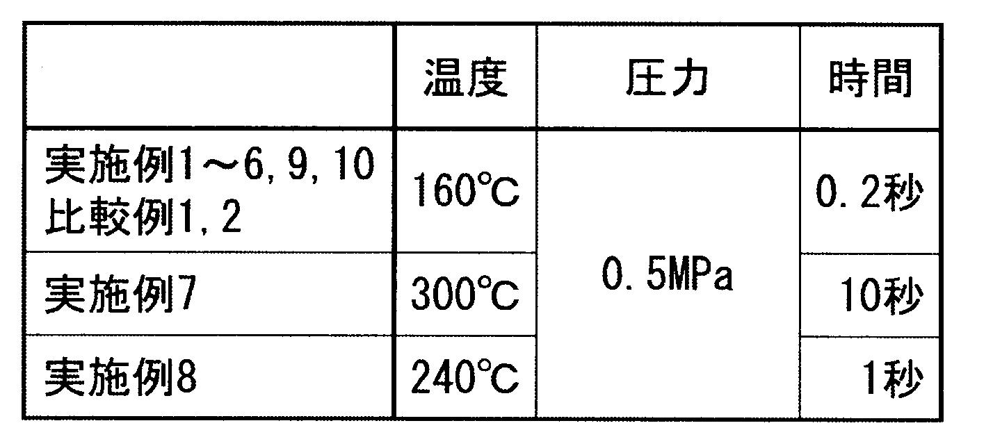
ワイヤボンディングテストの結果から、以下の基準で接着テープのワイヤボンディング性を判定した。
◎:ワイヤボンド不良の発生数が2/80以下。
○:ワイヤボンド不良の発生数が3/80以上9/80以下。
△:ワイヤボンド不良の発生数が10/80以上24/80以下。
×:ワイヤボンド不良の発生数が25/80以上。
◎:ワイヤボンド不良の発生数が2/80以下。
○:ワイヤボンド不良の発生数が3/80以上9/80以下。
△:ワイヤボンド不良の発生数が10/80以上24/80以下。
×:ワイヤボンド不良の発生数が25/80以上。
<打ち抜き加工性>
接着テープをリードフレームへ貼り付ける際には、接着テープを所望の形状に加工する必要があり、その加工は主に金型による打ち抜き加工によって実施される。そこで、各実施例及び比較例の接着テープについて、容易且つ迅速に打ち抜き加工を行えるか(打ち抜き加工性)を下記の手順で評価した。
テーピングマシンを使用して、Cuリードフレーム(208PIN LQFP用)へ接着テープを貼着させ、下記の基準で評価、判定を行った。
○:装置が止まることなく、50ピース連続で打ち抜くことが出来た。
×:50ピース連続で打ち抜く事が出来なかった(途中で装置が止まってしまった)。
接着テープをリードフレームへ貼り付ける際には、接着テープを所望の形状に加工する必要があり、その加工は主に金型による打ち抜き加工によって実施される。そこで、各実施例及び比較例の接着テープについて、容易且つ迅速に打ち抜き加工を行えるか(打ち抜き加工性)を下記の手順で評価した。
テーピングマシンを使用して、Cuリードフレーム(208PIN LQFP用)へ接着テープを貼着させ、下記の基準で評価、判定を行った。
○:装置が止まることなく、50ピース連続で打ち抜くことが出来た。
×:50ピース連続で打ち抜く事が出来なかった(途中で装置が止まってしまった)。
<耐熱性>
各実施例および比較例の接着テープについて、半導体装置組立工程での加熱工程に対して必要な耐熱性を有しているかを評価するため、下記の手順で、ボイドの発生の有無、および高温時接着力測定を行った。
各実施例および比較例の接着テープについて、半導体装置組立工程での加熱工程に対して必要な耐熱性を有しているかを評価するため、下記の手順で、ボイドの発生の有無、および高温時接着力測定を行った。
(ボイド)
接着テープを幅10mm、長さ50mmにカットし、銅板へ貼着し試験サンプル(1)とした。圧着条件は表:テーピング条件と同一で実施した。さらに、試験サンプル(1)を175℃1時間(温度条件:室温から175℃へ2.5℃/分で昇温させた)加熱処理をして試験サンプル(2)とした。
次に、試験サンプル(2)を240℃のヒーターブロックへ1分間載せた後、上記と同様に目視で発泡の状態を判定した(ボイド観察)。
接着テープを幅10mm、長さ50mmにカットし、銅板へ貼着し試験サンプル(1)とした。圧着条件は表:テーピング条件と同一で実施した。さらに、試験サンプル(1)を175℃1時間(温度条件:室温から175℃へ2.5℃/分で昇温させた)加熱処理をして試験サンプル(2)とした。
次に、試験サンプル(2)を240℃のヒーターブロックへ1分間載せた後、上記と同様に目視で発泡の状態を判定した(ボイド観察)。
(高温時接着強度測定)
接着テープを、幅20mm、長さ80mmにカットし、175℃1時間加熱処理を行い、試験サンプルとした。240℃のヒータブロック上へ金属層側を接触させる様にサンプルを載せ、引張り試験機を使用して、金属層と絶縁層との間の240℃における剥離強度(高温時接着強度)(g/cm)を測定した。測定は、剥離角度を90度とし、引張り速度は50mm/分で実施した。測定に先立って、予め測定サンプルの片側を10mmほど金属層と絶縁層間で引き剥がしておいて測定を行った。
接着テープを、幅20mm、長さ80mmにカットし、175℃1時間加熱処理を行い、試験サンプルとした。240℃のヒータブロック上へ金属層側を接触させる様にサンプルを載せ、引張り試験機を使用して、金属層と絶縁層との間の240℃における剥離強度(高温時接着強度)(g/cm)を測定した。測定は、剥離角度を90度とし、引張り速度は50mm/分で実施した。測定に先立って、予め測定サンプルの片側を10mmほど金属層と絶縁層間で引き剥がしておいて測定を行った。
上記の結果から、下記の基準で接着テープの耐熱性を判定した。
◎:ボイドなし、かつ、高温時接着強度100g/cm以上。
○:ボイドなし、かつ、高温時接着強度10g/cm以上100g/cm未満。
△:ボイドあり、および/または、高温時接着強度3g/cm以上10g/cm未満。
×:ボイドあり、かつ、高温時接着強度3g/cm未満(実用上問題あり)。
◎:ボイドなし、かつ、高温時接着強度100g/cm以上。
○:ボイドなし、かつ、高温時接着強度10g/cm以上100g/cm未満。
△:ボイドあり、および/または、高温時接着強度3g/cm以上10g/cm未満。
×:ボイドあり、かつ、高温時接着強度3g/cm未満(実用上問題あり)。
<リードフレーム(LF)への貼着け性>
各実施例及び比較例の接着テープが容易且つ迅速に被着体(リードフレーム)へ貼着できるかどうか(貼付け性)、下記の手順で評価した。
テーピングマシンを使用して、Cuリードフレーム(208PIN LQFP用)を使用し、圧着時間を0.2秒、圧力0.5MPaにて、接着テープの圧着温度を100℃~300℃の範囲で変更して貼付け試験を行い、接着テープが接着可能な最低温度(接着可能温度)を求めた。
◎:接着可能温度が200℃未満。
○:接着可能温度が200℃以上250℃未満。
△:接着可能温度が250℃以上。
各実施例及び比較例の接着テープが容易且つ迅速に被着体(リードフレーム)へ貼着できるかどうか(貼付け性)、下記の手順で評価した。
テーピングマシンを使用して、Cuリードフレーム(208PIN LQFP用)を使用し、圧着時間を0.2秒、圧力0.5MPaにて、接着テープの圧着温度を100℃~300℃の範囲で変更して貼付け試験を行い、接着テープが接着可能な最低温度(接着可能温度)を求めた。
◎:接着可能温度が200℃未満。
○:接着可能温度が200℃以上250℃未満。
△:接着可能温度が250℃以上。
<加工後の絶縁性の確保>
各実施例及び比較例の接着テープについて、打ち抜き加工を行った後も絶縁性を確保できるかどうか、以下の手順で評価した。
テーピングマシンを使用して、下記の工程を連続で50ショット実施した。
接着テープの打ち抜き工程:金型により接着テープをリング状に打ち抜いた。
接着テープの接着工程:ヒータブロック上にCuリードフレーム(208PIN LQFP用)を置き、リング状に打ち抜いた接着テープを金属ロッドで押し付け、加熱および加圧を行って、リードフレームと接着テープとを貼り合わせた。
接着テープを貼り付けたリードフレームの状態を顕微鏡を用いて観察し、接着テープ由来の金属層がリードフレームへ接触している数(接触したLF数)を数え、下記の基準で絶縁性の評価を行った。
○:接触したLF数が、2ピース以下。
△:接触したLF数が、3ピース以上5ピース以下。
×:接触したLF数が、6ピース以上。
各実施例及び比較例の接着テープについて、打ち抜き加工を行った後も絶縁性を確保できるかどうか、以下の手順で評価した。
テーピングマシンを使用して、下記の工程を連続で50ショット実施した。
接着テープの打ち抜き工程:金型により接着テープをリング状に打ち抜いた。
接着テープの接着工程:ヒータブロック上にCuリードフレーム(208PIN LQFP用)を置き、リング状に打ち抜いた接着テープを金属ロッドで押し付け、加熱および加圧を行って、リードフレームと接着テープとを貼り合わせた。
接着テープを貼り付けたリードフレームの状態を顕微鏡を用いて観察し、接着テープ由来の金属層がリードフレームへ接触している数(接触したLF数)を数え、下記の基準で絶縁性の評価を行った。
○:接触したLF数が、2ピース以下。
△:接触したLF数が、3ピース以上5ピース以下。
×:接触したLF数が、6ピース以上。
<電気的信頼性試験>
下記の工程によりテーピングマシンを使用して各実施例及び比較例の接着テープをリードフレームに貼り合わせた。
接着テープの打ち抜き工程:金型により接着テープをリング状に打ち抜いた。
接着テープの接着工程:ヒータブロック上にCuリードフレーム(208PIN LQFP用)を置き、リング状に打ち抜いた接着テープを金属ロッドで押し付け、加熱および加圧を行って、リードフレームと接着テープとを貼り合わせた。
次に、上記の接着テープ付きリードフレームを、窒素置換した熱風循環型オーブン内に入れ、接着テープのキュアーを行い熱硬化させた。なお、200℃/1時間の条件とした。
次に、キュアー後の接着テープ付きリードフレームを使用し、以下の手順で図4のような半導体パッケージ100を組み立てた。
ダイボンディング:半導体チップ45をダイボンディング用銀ペーストを用いて、ダイパッド43に接着し、175℃で1時間硬化させた。
ワイヤーボンディング:ワイヤーボンダーにより、ワイヤ(金線)31、33、34で半導体チップ45上のワイヤーパッドとインナーリード41線端部の銀メッキ部分、半導体チップ45上のワイヤーパッドと接着テープ10Aの金属層、及び接着テープ10Aの金属層と電源用のインナーリードを配線した。
モールディング:エポキシ系モールド剤でトランスファーモールドし、パッケージ47を形成した。
仕上げ工程:ホーミング、ダイカット、アウターリード部のメッキ等の工程を実施し、半導体パッケージ100を作製した。
次に上記のようにして得られた半導体パッケージ100のアウターリード部に電気を流して、電気的信頼性試験を行った。電気的信頼性試験は、5ボルト印加、85℃、85%RHの条件で96時間実施した。
そして、下記の基準で電気的信頼性の評価を行った。
試験中抵抗値が1×10⁶以下となった場合をショートと判断した。
○:96時間でショートなし。
×:96時間でショートあり。
下記の工程によりテーピングマシンを使用して各実施例及び比較例の接着テープをリードフレームに貼り合わせた。
接着テープの打ち抜き工程:金型により接着テープをリング状に打ち抜いた。
接着テープの接着工程:ヒータブロック上にCuリードフレーム(208PIN LQFP用)を置き、リング状に打ち抜いた接着テープを金属ロッドで押し付け、加熱および加圧を行って、リードフレームと接着テープとを貼り合わせた。
次に、上記の接着テープ付きリードフレームを、窒素置換した熱風循環型オーブン内に入れ、接着テープのキュアーを行い熱硬化させた。なお、200℃/1時間の条件とした。
次に、キュアー後の接着テープ付きリードフレームを使用し、以下の手順で図4のような半導体パッケージ100を組み立てた。
ダイボンディング:半導体チップ45をダイボンディング用銀ペーストを用いて、ダイパッド43に接着し、175℃で1時間硬化させた。
ワイヤーボンディング:ワイヤーボンダーにより、ワイヤ(金線)31、33、34で半導体チップ45上のワイヤーパッドとインナーリード41線端部の銀メッキ部分、半導体チップ45上のワイヤーパッドと接着テープ10Aの金属層、及び接着テープ10Aの金属層と電源用のインナーリードを配線した。
モールディング:エポキシ系モールド剤でトランスファーモールドし、パッケージ47を形成した。
仕上げ工程:ホーミング、ダイカット、アウターリード部のメッキ等の工程を実施し、半導体パッケージ100を作製した。
次に上記のようにして得られた半導体パッケージ100のアウターリード部に電気を流して、電気的信頼性試験を行った。電気的信頼性試験は、5ボルト印加、85℃、85%RHの条件で96時間実施した。
そして、下記の基準で電気的信頼性の評価を行った。
試験中抵抗値が1×10⁶以下となった場合をショートと判断した。
○:96時間でショートなし。
×:96時間でショートあり。
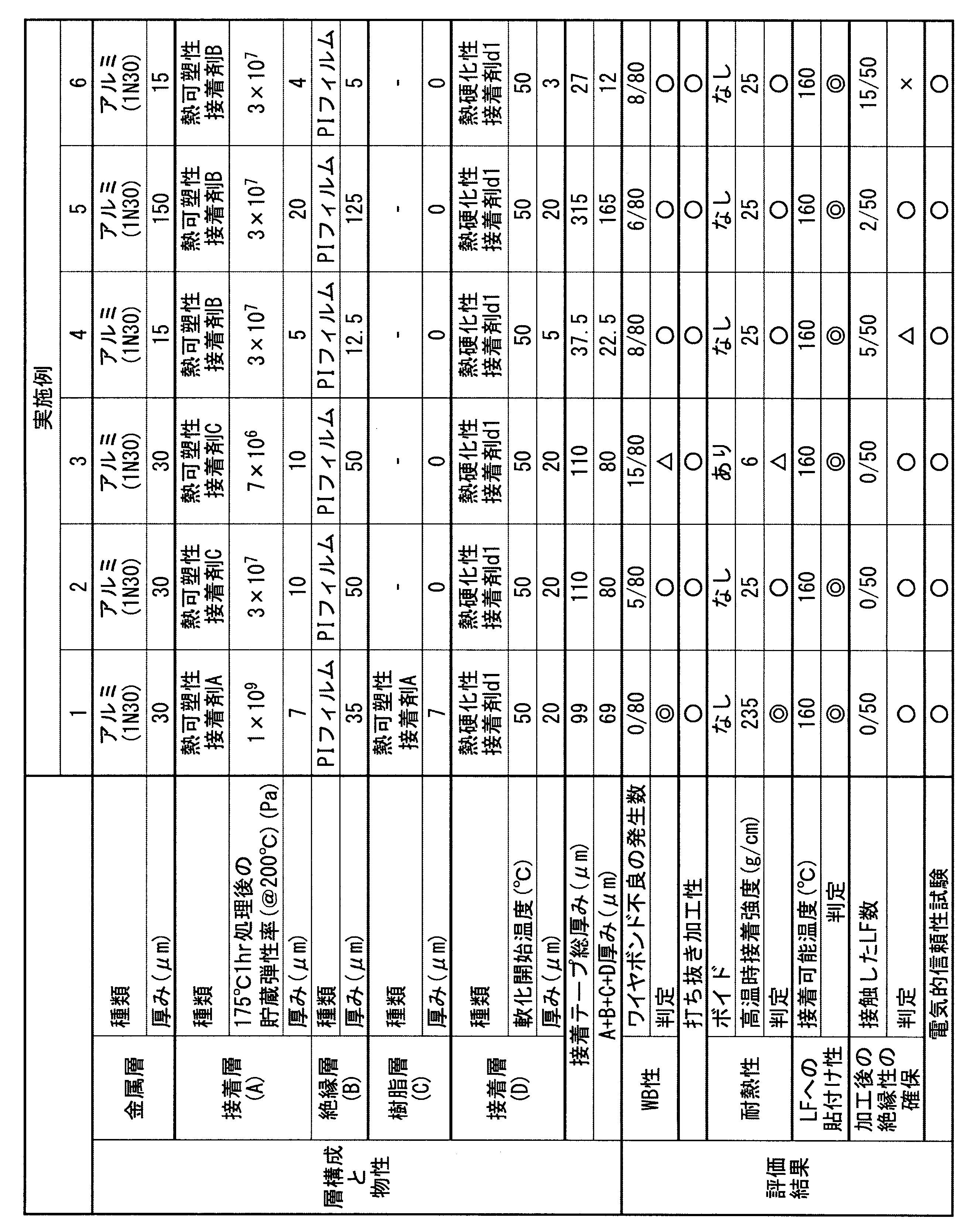

表2~3中、「PI」はポリイミドを示す。「A+B+C+D厚み」は、接着層(A)と絶縁層(B)と樹脂層(C)と接着層(D)との合計の厚みであり、接着テープの総厚みから金属層の厚みを除いた厚みである。
金属層、接着層(A)、絶縁層(B)、樹脂層(C)、接着層(D)はこの順に積層しており、接着層(A)が第一の接着層、接着層(D)が第二の接着層である。
金属層、接着層(A)、絶縁層(B)、樹脂層(C)、接着層(D)はこの順に積層しており、接着層(A)が第一の接着層、接着層(D)が第二の接着層である。
上記の結果から、接着層(A)の175℃1時間の加熱処理後の200℃における貯蔵弾性率と、ワイヤボンディング性との間に相関関係があることが確認できた。
前記貯蔵弾性率が1×10⁶Pa以上であり、金属層の厚みが200μm以下の実施例1~11の接着テープは、ワイヤボンディング性、打ち抜き加工性、電気的信頼性ともに良好であった。
これに対して、接着層(A)の前記貯蔵弾性率が1×10⁶Pa未満の比較例1の接着テープは、ワイヤボンディングにて接続不良が多く、実用上問題があった。
金属層の厚みが200μm超の比較例2の接着テープは、打ち抜き加工性について実用上問題があった。
前記貯蔵弾性率が1×10⁶Pa以上であり、金属層の厚みが200μm以下の実施例1~11の接着テープは、ワイヤボンディング性、打ち抜き加工性、電気的信頼性ともに良好であった。
これに対して、接着層(A)の前記貯蔵弾性率が1×10⁶Pa未満の比較例1の接着テープは、ワイヤボンディングにて接続不良が多く、実用上問題があった。
金属層の厚みが200μm超の比較例2の接着テープは、打ち抜き加工性について実用上問題があった。
1 金属層
3 第一の接着層
5 絶縁層
7 第二の接着層
9 樹脂層
10 接着シート
20 接着シート
3 第一の接着層
5 絶縁層
7 第二の接着層
9 樹脂層
10 接着シート
20 接着シート
Claims (10)
- 金属層と、第一の接着層と、絶縁層と、第二の接着層とがこの順に積層しており、
前記金属層の厚みが200μm以下であり、
前記第一の接着層の、175℃1時間の加熱処理後の200℃における貯蔵弾性率が1×10⁶Pa以上であることを特徴とする電子部品用接着テープ。 - 前記第二の接着層の軟化開始温度が0~300℃である、請求項1に記載の電子部品用接着テープ。
- 総厚みが500μm以下である、請求項1又は2に記載の電子部品用接着テープ。
- 下記の測定方法で測定される高温時接着強度が3g/cm以上である、請求項1~3のいずれか一項に記載の電子部品用接着テープ。
高温時接着強度の測定方法:電子部品用接着テープに対して175℃1時間加熱処理を行った後、金属層と絶縁層との間の240℃における剥離強度(g/cm)を、引張り試験機を使用して、剥離角度90度、引張り速度50mm/分の条件で測定し、その値を高温時接着強度とする。 - 前記絶縁層の厚みが5μm以上である、請求項1~4のいずれか一項に記載の電子部品用接着テープ。
- 前記第二の接着層の厚みが5μm以上である、請求項1~5のいずれか一項に記載の電子部品用接着テープ。
- 総厚みから前記金属層の厚みを除いた厚みが15μm以上である、請求項1~6のいずれか一項に記載の電子部品用接着テープ。
- 前記第一の接着層が、ガラス転移温度150~350℃の熱可塑性ポリイミド樹脂を含む、請求項1~7のいずれか一項に記載の電子部品用接着テープ。
- 前記金属層が、アルミニウム又はアルミニウム合金からなる、請求項1~8のいずれか一項に記載の電子部品用接着テープ。
- 前記金属層のアルミニウム純度が90%以上である、請求項9に記載の電子部品用接着テープ。
Applications Claiming Priority (2)
| Application Number | Priority Date | Filing Date | Title |
|---|---|---|---|
| JP2015-191500 | 2015-09-29 | ||
| JP2015191500A JP6698306B2 (ja) | 2015-09-29 | 2015-09-29 | リードフレーム固定用接着テープ |
Publications (1)
| Publication Number | Publication Date |
|---|---|
| WO2017057519A1 true WO2017057519A1 (ja) | 2017-04-06 |
Family
ID=58427485
Family Applications (1)
| Application Number | Title | Priority Date | Filing Date |
|---|---|---|---|
| PCT/JP2016/078733 Ceased WO2017057519A1 (ja) | 2015-09-29 | 2016-09-28 | 電子部品用接着テープ |
Country Status (3)
| Country | Link |
|---|---|
| JP (1) | JP6698306B2 (ja) |
| TW (1) | TWI618775B (ja) |
| WO (1) | WO2017057519A1 (ja) |
Families Citing this family (6)
| Publication number | Priority date | Publication date | Assignee | Title |
|---|---|---|---|---|
| JP7024454B2 (ja) * | 2018-01-30 | 2022-02-24 | 大日本印刷株式会社 | 積層体および物品 |
| KR102840281B1 (ko) * | 2018-08-03 | 2025-07-30 | 미쯔비시 케미컬 주식회사 | 적층체 및 에폭시 수지 시트의 제조 방법 |
| JP7412531B2 (ja) * | 2020-03-05 | 2024-01-12 | リンテック株式会社 | ロール体 |
| JP7446887B2 (ja) * | 2020-03-30 | 2024-03-11 | リンテック株式会社 | フィルム状接着剤 |
| JP7527823B2 (ja) * | 2020-03-30 | 2024-08-05 | リンテック株式会社 | フィルム状接着剤 |
| JP2022047704A (ja) * | 2020-09-14 | 2022-03-25 | 日東電工株式会社 | 粘着シート |
Citations (10)
| Publication number | Priority date | Publication date | Assignee | Title |
|---|---|---|---|---|
| JPH05179210A (ja) * | 1991-04-24 | 1993-07-20 | Ciba Geigy Ag | 熱伝導性接着フィルム、熱伝導性接着剤層を有する積層品及びそれらの使用品 |
| JPH0693238A (ja) * | 1992-09-11 | 1994-04-05 | Tomoegawa Paper Co Ltd | 接着シート |
| JPH06345964A (ja) * | 1993-06-11 | 1994-12-20 | Hitachi Chem Co Ltd | 耐熱性熱硬化性樹脂組成物、接着剤シート、接着剤付きポリイミドフィルム及び金属はく張りポリイミドフィルム |
| JPH07235626A (ja) * | 1993-12-27 | 1995-09-05 | Mitsui Toatsu Chem Inc | 放熱板付リードフレーム及びそれを用いた半導体装置 |
| JP2000008020A (ja) * | 1998-06-26 | 2000-01-11 | Tomoegawa Paper Co Ltd | 電子部品用接着テープ |
| JP2003188334A (ja) * | 2001-12-17 | 2003-07-04 | Tomoegawa Paper Co Ltd | 半導体装置製造用接着シート |
| JP2003249617A (ja) * | 1999-11-10 | 2003-09-05 | Hitachi Chem Co Ltd | 半導体用接着フィルム |
| JP2003253220A (ja) * | 2002-02-27 | 2003-09-10 | Sumitomo Bakelite Co Ltd | フィルム状接着剤及び半導体接着テープ |
| JP2003332510A (ja) * | 2002-05-15 | 2003-11-21 | Mitsui Chemicals Inc | 放熱板付きリードフレーム固定用接着基材 |
| JP2009001793A (ja) * | 2008-06-06 | 2009-01-08 | Kaneka Corp | 接着剤 |
Family Cites Families (3)
| Publication number | Priority date | Publication date | Assignee | Title |
|---|---|---|---|---|
| JPH09289278A (ja) * | 1996-04-23 | 1997-11-04 | Hitachi Cable Ltd | 半導体装置用リードフレームの製造方法 |
| KR100227120B1 (ko) * | 1997-02-28 | 1999-10-15 | 윤종용 | 엘오씨(loc)리드와 표준형 리드가 복합된 구조를 갖는 반도체 칩 패키지 |
| JP3147071B2 (ja) * | 1998-01-19 | 2001-03-19 | 日本電気株式会社 | 半導体装置及びその製造方法 |
-
2015
- 2015-09-29 JP JP2015191500A patent/JP6698306B2/ja active Active
-
2016
- 2016-09-28 WO PCT/JP2016/078733 patent/WO2017057519A1/ja not_active Ceased
- 2016-09-29 TW TW105131273A patent/TWI618775B/zh active
Patent Citations (10)
| Publication number | Priority date | Publication date | Assignee | Title |
|---|---|---|---|---|
| JPH05179210A (ja) * | 1991-04-24 | 1993-07-20 | Ciba Geigy Ag | 熱伝導性接着フィルム、熱伝導性接着剤層を有する積層品及びそれらの使用品 |
| JPH0693238A (ja) * | 1992-09-11 | 1994-04-05 | Tomoegawa Paper Co Ltd | 接着シート |
| JPH06345964A (ja) * | 1993-06-11 | 1994-12-20 | Hitachi Chem Co Ltd | 耐熱性熱硬化性樹脂組成物、接着剤シート、接着剤付きポリイミドフィルム及び金属はく張りポリイミドフィルム |
| JPH07235626A (ja) * | 1993-12-27 | 1995-09-05 | Mitsui Toatsu Chem Inc | 放熱板付リードフレーム及びそれを用いた半導体装置 |
| JP2000008020A (ja) * | 1998-06-26 | 2000-01-11 | Tomoegawa Paper Co Ltd | 電子部品用接着テープ |
| JP2003249617A (ja) * | 1999-11-10 | 2003-09-05 | Hitachi Chem Co Ltd | 半導体用接着フィルム |
| JP2003188334A (ja) * | 2001-12-17 | 2003-07-04 | Tomoegawa Paper Co Ltd | 半導体装置製造用接着シート |
| JP2003253220A (ja) * | 2002-02-27 | 2003-09-10 | Sumitomo Bakelite Co Ltd | フィルム状接着剤及び半導体接着テープ |
| JP2003332510A (ja) * | 2002-05-15 | 2003-11-21 | Mitsui Chemicals Inc | 放熱板付きリードフレーム固定用接着基材 |
| JP2009001793A (ja) * | 2008-06-06 | 2009-01-08 | Kaneka Corp | 接着剤 |
Also Published As
| Publication number | Publication date |
|---|---|
| JP6698306B2 (ja) | 2020-05-27 |
| TWI618775B (zh) | 2018-03-21 |
| TW201715001A (zh) | 2017-05-01 |
| JP2017066233A (ja) | 2017-04-06 |
Similar Documents
| Publication | Publication Date | Title |
|---|---|---|
| JP7044200B2 (ja) | ポリイミド、接着剤、フィルム状接着材、接着層、接着シート、樹脂付銅箔、銅張積層板、プリント配線板、並びに多層配線板及びその製造方法 | |
| TWI754668B (zh) | 可撓性印刷線路板用覆銅積層板及可撓性印刷線路板 | |
| JP5534378B2 (ja) | ポリイミド系接着剤組成物、硬化物、接着シート、積層体、フレキシブルプリント基板 | |
| TWI690578B (zh) | 黏著劑組成物、薄膜狀黏著材料、黏著層、黏著薄片、附有樹脂的銅箔、覆銅積層板、可撓性覆銅積層板、印刷線路板、可撓性印刷線路板、多層線路板、印刷電路板及可撓性印刷電路板 | |
| TWI618775B (zh) | 電子零件用黏著膠帶 | |
| JP6303503B2 (ja) | 樹脂組成物、硬化膜、積層フィルム、および半導体装置の製造方法 | |
| CN102137906A (zh) | 两面粘接膜和使用了该两面粘接膜的电子部件模块 | |
| CN101522744A (zh) | 聚酰胺酰亚胺树脂、粘接剂、挠性基板材料、挠性层叠板及挠性印刷电路板 | |
| KR101475139B1 (ko) | 반도체 장치 제조용 마스크 시트 및 이를 이용한 반도체 장치의 제조 방법 | |
| JP2018168372A (ja) | 接着剤、フィルム状接着材、接着層、接着シート、樹脂付銅箔、銅張積層板、プリント配線板、並びに多層配線板及びその製造方法 | |
| JP2011042730A (ja) | 接着剤組成物、フィルム状接着剤、接着シート及び半導体装置 | |
| JP2020105493A (ja) | ポリイミド、ポリイミド樹脂組成物、ポリイミドフィルム、接着剤、フィルム状接着材、接着層、接着シート、樹脂付銅箔、銅張積層板及びプリント配線板、並びに、ポリイミドの製造方法 | |
| JP7283441B2 (ja) | 組成物、反応物、接着剤、フィルム状接着材、接着層、接着シート、樹脂付銅箔、銅張積層板、プリント配線板、並びに多層配線板及びその製造方法 | |
| JP2004217862A (ja) | 耐熱性接着剤並びにこの接着剤を用いた積層物、接着剤付き放熱板及び接着剤付金属箔 | |
| JP2003138241A (ja) | 耐熱性接着剤並びにこの接着剤を用いた積層物、接着剤付き放熱板、接着剤付金属箔 | |
| JP2003119440A (ja) | 半導体用接着フィルム、およびこれを用いた半導体用接着フィルム付きリードフレームならびに半導体装置 | |
| JP6487829B2 (ja) | 熱伝導性熱硬化型接着剤組成物及び熱伝導性熱硬化型接着シート | |
| JP2002129126A (ja) | 半導体装置用接着剤組成物および接着シート | |
| JP5890253B2 (ja) | 熱伝導性熱硬化型接着剤組成物及び熱伝導性熱硬化型接着剤シート | |
| JP5732881B2 (ja) | 半導体用接着フィルム、接着シート、半導体ウエハ及び半導体装置 | |
| WO2010024236A1 (ja) | 両面接着フィルム及びこれを用いた電子部品モジュール | |
| JP5531683B2 (ja) | 層間接着剤 | |
| JP6173656B2 (ja) | 両面接着フィルム及びこれを用いた電子部品モジュール | |
| JP3532792B2 (ja) | 電子部品用接着剤及び接着テープ | |
| JP2000226560A (ja) | 電子部品用接着テープ |
Legal Events
| Date | Code | Title | Description |
|---|---|---|---|
| 121 | Ep: the epo has been informed by wipo that ep was designated in this application |
Ref document number: 16851690 Country of ref document: EP Kind code of ref document: A1 |
|
| NENP | Non-entry into the national phase |
Ref country code: DE |
|
| 122 | Ep: pct application non-entry in european phase |
Ref document number: 16851690 Country of ref document: EP Kind code of ref document: A1 |