WO2017014015A1 - ロータ、回転電機、ロータ製造方法、及びロータ製造装置 - Google Patents
ロータ、回転電機、ロータ製造方法、及びロータ製造装置 Download PDFInfo
- Publication number
- WO2017014015A1 WO2017014015A1 PCT/JP2016/069301 JP2016069301W WO2017014015A1 WO 2017014015 A1 WO2017014015 A1 WO 2017014015A1 JP 2016069301 W JP2016069301 W JP 2016069301W WO 2017014015 A1 WO2017014015 A1 WO 2017014015A1
- Authority
- WO
- WIPO (PCT)
- Prior art keywords
- rotor
- rotor core
- permanent magnet
- cover
- rotor cover
- Prior art date
- Legal status (The legal status is an assumption and is not a legal conclusion. Google has not performed a legal analysis and makes no representation as to the accuracy of the status listed.)
- Ceased
Links
Images










Classifications
-
- H—ELECTRICITY
- H02—GENERATION; CONVERSION OR DISTRIBUTION OF ELECTRIC POWER
- H02K—DYNAMO-ELECTRIC MACHINES
- H02K1/00—Details of the magnetic circuit
- H02K1/06—Details of the magnetic circuit characterised by the shape, form or construction
- H02K1/22—Rotating parts of the magnetic circuit
- H02K1/27—Rotor cores with permanent magnets
- H02K1/2706—Inner rotors
- H02K1/272—Inner rotors the magnetisation axis of the magnets being perpendicular to the rotor axis
- H02K1/274—Inner rotors the magnetisation axis of the magnets being perpendicular to the rotor axis the rotor consisting of two or more circumferentially positioned magnets
- H02K1/2753—Inner rotors the magnetisation axis of the magnets being perpendicular to the rotor axis the rotor consisting of two or more circumferentially positioned magnets the rotor consisting of magnets or groups of magnets arranged with alternating polarity
- H02K1/276—Magnets embedded in the magnetic core, e.g. interior permanent magnets [IPM]
-
- H—ELECTRICITY
- H02—GENERATION; CONVERSION OR DISTRIBUTION OF ELECTRIC POWER
- H02K—DYNAMO-ELECTRIC MACHINES
- H02K15/00—Processes or apparatus specially adapted for manufacturing, assembling, maintaining or repairing of dynamo-electric machines
- H02K15/02—Processes or apparatus specially adapted for manufacturing, assembling, maintaining or repairing of dynamo-electric machines of stator or rotor bodies
- H02K15/03—Processes or apparatus specially adapted for manufacturing, assembling, maintaining or repairing of dynamo-electric machines of stator or rotor bodies having permanent magnets
-
- H—ELECTRICITY
- H02—GENERATION; CONVERSION OR DISTRIBUTION OF ELECTRIC POWER
- H02K—DYNAMO-ELECTRIC MACHINES
- H02K1/00—Details of the magnetic circuit
- H02K1/06—Details of the magnetic circuit characterised by the shape, form or construction
- H02K1/22—Rotating parts of the magnetic circuit
- H02K1/26—Rotor cores with slots for windings
-
- H—ELECTRICITY
- H02—GENERATION; CONVERSION OR DISTRIBUTION OF ELECTRIC POWER
- H02K—DYNAMO-ELECTRIC MACHINES
- H02K1/00—Details of the magnetic circuit
- H02K1/06—Details of the magnetic circuit characterised by the shape, form or construction
- H02K1/22—Rotating parts of the magnetic circuit
- H02K1/27—Rotor cores with permanent magnets
- H02K1/2706—Inner rotors
- H02K1/272—Inner rotors the magnetisation axis of the magnets being perpendicular to the rotor axis
- H02K1/274—Inner rotors the magnetisation axis of the magnets being perpendicular to the rotor axis the rotor consisting of two or more circumferentially positioned magnets
- H02K1/2753—Inner rotors the magnetisation axis of the magnets being perpendicular to the rotor axis the rotor consisting of two or more circumferentially positioned magnets the rotor consisting of magnets or groups of magnets arranged with alternating polarity
- H02K1/278—Surface mounted magnets; Inset magnets
-
- H—ELECTRICITY
- H02—GENERATION; CONVERSION OR DISTRIBUTION OF ELECTRIC POWER
- H02K—DYNAMO-ELECTRIC MACHINES
- H02K1/00—Details of the magnetic circuit
- H02K1/06—Details of the magnetic circuit characterised by the shape, form or construction
- H02K1/22—Rotating parts of the magnetic circuit
- H02K1/28—Means for mounting or fastening rotating magnetic parts on to, or to, the rotor structures
-
- H—ELECTRICITY
- H02—GENERATION; CONVERSION OR DISTRIBUTION OF ELECTRIC POWER
- H02K—DYNAMO-ELECTRIC MACHINES
- H02K15/00—Processes or apparatus specially adapted for manufacturing, assembling, maintaining or repairing of dynamo-electric machines
- H02K15/02—Processes or apparatus specially adapted for manufacturing, assembling, maintaining or repairing of dynamo-electric machines of stator or rotor bodies
- H02K15/021—Magnetic cores
- H02K15/026—Wound cores
-
- H—ELECTRICITY
- H02—GENERATION; CONVERSION OR DISTRIBUTION OF ELECTRIC POWER
- H02K—DYNAMO-ELECTRIC MACHINES
- H02K23/00—DC commutator motors or generators having mechanical commutator; Universal AC/DC commutator motors
- H02K23/02—DC commutator motors or generators having mechanical commutator; Universal AC/DC commutator motors characterised by arrangement for exciting
- H02K23/04—DC commutator motors or generators having mechanical commutator; Universal AC/DC commutator motors characterised by arrangement for exciting having permanent magnet excitation
-
- H—ELECTRICITY
- H02—GENERATION; CONVERSION OR DISTRIBUTION OF ELECTRIC POWER
- H02K—DYNAMO-ELECTRIC MACHINES
- H02K21/00—Synchronous motors having permanent magnets; Synchronous generators having permanent magnets
- H02K21/12—Synchronous motors having permanent magnets; Synchronous generators having permanent magnets with stationary armatures and rotating magnets
- H02K21/14—Synchronous motors having permanent magnets; Synchronous generators having permanent magnets with stationary armatures and rotating magnets with magnets rotating within the armatures
-
- H—ELECTRICITY
- H02—GENERATION; CONVERSION OR DISTRIBUTION OF ELECTRIC POWER
- H02K—DYNAMO-ELECTRIC MACHINES
- H02K29/00—Motors or generators having non-mechanical commutating devices, e.g. discharge tubes or semiconductor devices
- H02K29/06—Motors or generators having non-mechanical commutating devices, e.g. discharge tubes or semiconductor devices with position sensing devices
- H02K29/08—Motors or generators having non-mechanical commutating devices, e.g. discharge tubes or semiconductor devices with position sensing devices using magnetic effect devices, e.g. Hall-plates, magneto-resistors
Definitions
- the present invention relates to a rotor, a rotating electrical machine, a rotor manufacturing method, and a rotor manufacturing apparatus.
- JP 1999-299149 A discloses a rotor used for a rotating electrical machine.
- the rotor includes a yoke having a magnet attached to the outer periphery thereof and a cover covering the outer circumferential surface of the magnet.
- the magnet is provided with a notch at its circumferential end, and the cover is provided with a recess at its opening edge. Movement of the cover in the axial direction and the circumferential direction is restricted by the recess of the cover being locked in the notch between the adjacent magnets.
- An object of the present invention is to facilitate rotation prevention of a rotor cover.
- a rotor core unit comprising: a rotor core unit having a rotor core fixed integrally to a rotating shaft and a plurality of permanent magnets mounted along the circumferential direction of the rotor core; There is a first holding portion in contact with the outer peripheral edge at one end face of the direction and a second holding portion in contact with at least one of the other end face of the permanent magnet and the rotor core to axially hold the rotor core unit together with the first holding portion And a single cylindrical rotor cover covering the outer periphery of the rotor core.
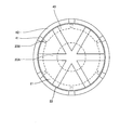
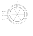
- FIG. 1 is a cross-sectional view showing a rotating electrical machine provided with a rotor according to an embodiment of the present invention.
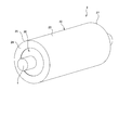
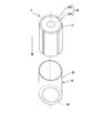
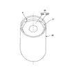
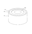
- FIG. 2 is a perspective view showing a rotor according to an embodiment of the present invention.
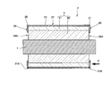
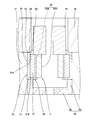
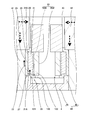
- FIG. 3 is a cross-sectional view taken along the line AA of FIG. 1, which is a plane including the rotation axis of the shaft.
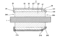
- FIG. 4 is a cross-sectional view taken along line AA of FIG. 1 showing a rotor in which the axial length of the rotor core is longer than the axial length of the permanent magnet.
- FIG. 1 is a cross-sectional view showing a rotating electrical machine provided with a rotor according to an embodiment of the present invention.
- FIG. 2 is a perspective view showing a rotor according to an embodiment of the present invention.
- FIG. 3 is a cross-sectional view taken along the line AA of FIG. 1, which is a plane including the rotation axis of the shaft.
- FIG. 4 is a
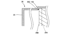
- FIG. 5 is a view showing a modification of the rotor in which the axial length of the rotor core is longer than the axial length of the permanent magnet, and is a cross-sectional view taken along the line AA of FIG. 6 is a view on arrow C in FIG.
- FIG. 7 is a cross-sectional view taken along the line DD in FIG.
- FIG. 8 is a cross-sectional view taken along the line EE in FIG.
- FIG. 9 is a cross-sectional view showing a rotor in which the axial length of the rotor core is shorter than the axial length of the permanent magnet.
- FIG. 10 is a block diagram of a rotor manufacturing apparatus according to an embodiment of the present invention, showing a part in cross section.
- FIG. 10 is a block diagram of a rotor manufacturing apparatus according to an embodiment of the present invention, showing a part in cross section.
- FIG. 11 is a perspective view showing an outer collet in a method of manufacturing a rotor according to an embodiment of the present invention.
- FIG. 12 is a perspective view for explaining the manufacturing process of the rotor, and shows the process of housing the rotor core in the rotor cover.
- FIG. 13 is a perspective view for explaining a manufacturing process of the rotor, and shows a state in which the rotor core is accommodated in the rotor cover.
- FIG. 14 is a cross-sectional view for explaining a manufacturing process of a rotor, and shows a rotor core and a rotor cover accommodated in a regulating member.
- FIG. 12 is a perspective view for explaining the manufacturing process of the rotor, and shows the process of housing the rotor core in the rotor cover.
- FIG. 13 is a perspective view for explaining a manufacturing process of the rotor, and shows a state in which the rotor core is accommodated in the rotor cover.
- FIG. 15 is a perspective view for explaining the manufacturing process of the rotor, and shows a state in which the outer collet and the inner collet are arranged.
- FIG. 16 is a plan view for explaining the manufacturing process of the rotor, and shows a state in which the outer collet and the inner collet are arranged.
- FIG. 17 is a cross-sectional view for explaining a manufacturing process of the rotor, and shows a state in which the first pressing process is completed.
- FIG. 18 is a plan view for illustrating the manufacturing process of the rotor, and shows a state in which the first pressing step is completed.
- FIG. 19 is a perspective view for explaining the manufacturing process of the rotor, and shows a state in which the outer collet and the inner collet are removed from the state in which the first pressing step is completed.
- FIG. 20 is a plan view for explaining a second pressing step in the manufacturing process of the rotor.
- FIG. 21 is a plan view for illustrating the manufacturing process of the rotor, and shows a state in which the second pressing process is completed.
- FIG. 22 is a perspective view for explaining the manufacturing process of the rotor, and shows a state in which the outer collet is removed from the state in which the second pressing step is completed.
- FIG. 20 is a plan view for explaining a second pressing step in the manufacturing process of the rotor.
- FIG. 21 is a plan view for illustrating the manufacturing process of the rotor, and shows a state in which the second pressing process is completed.
- FIG. 22 is a perspective view for explaining the manufacturing process of the rotor, and shows a state in which the outer
- FIG. 23 is a cross-sectional view for explaining a manufacturing process of the rotor, and shows a state before performing the first pressing step when the axial length of the rotor core is longer than the axial length of the permanent magnet.
- FIG. 24 is a cross-sectional view for explaining a manufacturing process of the rotor, and shows a state in which the first pressing step is completed when the axial length of the rotor core is longer than the axial length of the permanent magnet.
- FIG. 25 is a cross-sectional view showing a cross section different from FIG. 24 for explaining the manufacturing process of the rotor, and the first pressing step is completed when the axial length of the rotor core is longer than the axial length of the permanent magnet Indicates the status.
- FIG. 24 is a cross-sectional view for explaining a manufacturing process of the rotor, and shows a state before performing the first pressing step when the axial length of the rotor core is longer than the axial length of the permanent magnet.
- FIG. 26 is a cross-sectional view for explaining a manufacturing process of the rotor, and shows a state in which the second pressing step is completed when the axial length of the rotor core is longer than the axial length of the permanent magnet.
- FIG. 27 is a view showing a modified example of the present invention, and is a cross-sectional view showing a state before forming the upper surface portion of the rotor cover.
- FIG. 1 is a cross-sectional view showing a cross section of a rotary electric machine 100 provided with a rotor 2 according to the present embodiment, cut in a direction perpendicular to the rotation axis.
- the rotary electric machine 100 functions as at least one of a motor and a generator. As shown in FIG. 1, the rotary electric machine 100 has a shaft 1 as a rotatable rotation shaft, a rotor 2 integrally fixed to the shaft 1, and a predetermined gap from the rotor 2 on the outer peripheral side of the rotor 2. And a stator 3 disposed.
- the rotor 2 includes a rotor core unit 4 and a rotor cover 22 that accommodates the rotor core unit 4.
- the rotor core unit 4 has a rotor core 20 fixed to the outer periphery of the shaft 1 and rotating with the shaft 1 and a plurality of permanent magnets 21 attached to the outer peripheral surface of the rotor core 20 at equal intervals in the circumferential direction.
- the rotor core unit 4 has six permanent magnets 21 aligned in the circumferential direction.
- the rotor core unit 4 is not limited to this, and may have seven or more permanent magnets 21 aligned in the circumferential direction, or may have any of two to five permanent magnets 21.
- the rotor core 20 has a central portion 20A provided inside the plurality of permanent magnets 21 and a plurality of projecting portions 20B formed to project radially outward from the central portion 20A.
- the shaft 1 is fixed to the rotor core 20 through the central portion 20A.
- the protrusions 20B are provided at equal intervals in the circumferential direction, and are disposed between the adjacent permanent magnets 21 respectively.
- the permanent magnet 21 is disposed between the adjacent protrusions 20B of the rotor core 20 and fixed to the central portion 20A.
- the stator 3 includes an annular stator core 31 disposed to surround the rotor 2 with the rotor 2 via a predetermined gap, and a winding 32 wound on the stator core 31.
- the stator core 31 includes an annular yoke portion 33, a plurality of teeth 34 protruding radially inward from the yoke portion 33 and disposed at predetermined intervals in the circumferential direction, and the adjacent teeth 34, the inside of the yoke portion 33 And a slot 35 defined on the circumferential side.
- the windings 32 are wound around the teeth 34 of the stator core 31, and coils are formed on the teeth 34.
- the end of the winding 32 is connected to an electrode (not shown) provided on the stator 3.
- the stator core 31 is magnetized, and the rotor 2 rotates about the shaft 1 by the action of the permanent magnet 21 of the rotor core unit 4.
- FIG. 2 is a perspective view showing the rotor 2 in the present embodiment.
- FIG. 3 is a cross-sectional view of the shaft 1 and the rotor 2 along the line AA in FIG.
- the rotor cover 22 is formed in a bottomed cylindrical shape made of nonmagnetic stainless steel accommodating the rotor core unit 4 having the rotor core 20 and the permanent magnet 21 attached to the rotor core 20. As shown in FIG. 3, the rotor cover 22 is bent from the cylindrical portion 23 provided on the cylindrical cylindrical portion 23 covering the outer periphery of the rotor core 20 and on one axial side (left side in FIG. 3) of the cylindrical portion 23. It has the upper surface part 24 as a 1st clamping part formed, and the bottom part 26 as a 2nd clamping part provided in the axial direction other side (right side in FIG. 3) of the cylindrical part 23. As shown in FIG. The rotor cover 22 is formed by processing a single member, and the cylindrical portion 23, the top portion 24, and the bottom portion 26 are integrally formed.
- the upper surface portion 24 is formed in an annular shape having a surface perpendicular to the axial direction and having a hole 24A larger in diameter than the shaft 1 at the center.
- the upper surface portion 24 is formed between one end portion of the cylindrical portion 23 and has an upper surface corner 25 at the outer peripheral end that abuts on the outer peripheral edge 21A at one end surface of the permanent magnet 21 in the axial direction.
- the bottom portion 26 is formed in an annular shape having a surface perpendicular to the axial direction and having a hole 26A having a diameter larger than that of the shaft 1 at the center, as shown in FIG.
- the bottom portion 26 faces the other end surface of the permanent magnet 21 and abuts on the other end portion of at least one of the rotor core 20 and the permanent magnet 21 in the rotor core unit 4.
- the bottom portion 26 has a bottom corner portion 27 formed between the bottom portion 26 and the other end of the cylindrical portion 23 at the outer peripheral end. The specific configuration of the bottom 26 will be described in detail later.
- the upper surface portion 24 is formed by pressing an end portion on one axial side (left side in FIG. 3) of the cylindrical portion 23 radially inward.
- the upper surface corner 25 is formed to abut on the outer peripheral edge 21A of one end surface of the permanent magnet 21.
- the rotor core unit 4 includes an upper surface corner 25 of the upper surface 24 contacting the outer peripheral edge 21A of one end surface of the permanent magnet 21 and a bottom 26 contacting the other end of at least one of the rotor core 20 and the permanent magnet 21. It is clamped in the axial direction with a predetermined force. Thereby, the frictional force between the rotor cover 22 and the rotor core unit 4 becomes large, and the circumferential relative rotation between the rotor cover 22 and the rotor core unit 4 is restricted by the frictional force.
- the upper surface corner 25 may be in contact with a part of the entire circumference of the outer peripheral edge 21A at one end surface of the permanent magnet 21 in the axial direction. Further, in order to prevent the upper surface portion 24 from rotating the rotor cover 22 more securely, it is desirable to contact the end face on one side in the axial direction of the rotor core 20 and the permanent magnet 21 to increase the frictional force. It is sufficient that the portion 25 abuts on the outer peripheral edge 21A. That is, a portion other than the upper surface corner portion 25 in the upper surface portion 24 may be formed with a gap between itself and the rotor core unit 4.
- the holes 24A of the upper surface portion 24 and the holes 26A of the bottom portion 26 are smaller in diameter than the outer diameter of the central portion 20A of the rotor core 20.
- the top surface 24 and the bottom 26 extend to cover both axial end surfaces of the permanent magnet 21.
- a rotor cover 22 is formed with an upper surface portion 24 having an upper surface corner portion 25 to be in contact, and a bottom portion 26 to be in contact with at least one of the other end surface of the permanent magnet 21 and the rotor core 20. Therefore, in the rotor 2, relative rotation between the rotor core unit 4 and the rotor cover 22 in the circumferential direction can be restricted.
- FIG. 4 is a cross-sectional view showing a cross section taken along the line AA in FIG. 1 when the axial length of the rotor core 20 is longer than the axial length of the permanent magnet 21.
- the rotor core 20 in the case where the axial length of the rotor core 20 is longer than the axial length of the permanent magnet 21, the rotor core 20 has a projecting portion 20C that protrudes in the axial direction more than the other end face of the permanent magnet 21.
- the projecting portion 20C is configured by a part of the central portion 20A and a part of the projecting portion 20B which project in the axial direction more than the other end face of the permanent magnet 21.
- the bottom portion 26 of the rotor cover 22 has a core contact portion 120 that contacts the bottom surface of the rotor core 20 (the end surface of the protrusion 20C), and a connection portion 121 that connects the core contact portion 120 and the bottom corner portion 27. .
- connection portion 121 may be in contact with the outer peripheral surface of the rotor core 20 and the other axial end surface of the permanent magnet 21 as shown in FIG. 4, or may be separated as shown in FIG. In any case, the upper surface corner 25 abuts on the outer peripheral edge 21A at one axial end face of the permanent magnet 21 and the bottom 26 abuts on at least the projecting portion 20C of the rotor core 20 so that the rotor core unit 4 is axially Since it is held, rotation of the rotor cover 22 can be prevented. As shown in FIG.
- connection portion 121 abuts on the outer peripheral surface of the rotor core 20 and the other axial end surface of the permanent magnet 21, and the bottom corner portion 27 corresponds to the outer peripheral edge 21 B of the other end surface of the permanent magnet 21.
- the friction force is increased, and the rotation of the rotor cover 22 can be prevented more reliably.
- FIG. 6 is a view on arrow C in FIG. 3 and is a plan view showing the bottom portion 26 of the rotor cover 22.
- the recess 122 covering a part of the projection 20B constituting the projection 20C of the rotor core 20 is the rotor It is provided on the bottom 26 of the cover 22.
- FIG. 7 is a cross-sectional view taken along the line DD in FIG.
- the boundary between the protrusion 20B and the central portion 20A in the rotor core 20 is schematically represented by a broken line.
- FIG. 8 is a cross-sectional view taken along the line EE in FIG.
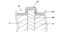
- the recess 122 is formed such that the inside in the axial direction (the inside of the rotor cover 22) is recessed along the outer peripheral edge at the end of the protrusion 20 ⁇ / b> C.
- a part of the protrusion 20B constituting the protrusion 20C is engaged with the recess 122, and the relative rotation between the rotor core 20 and the rotor cover 22 in the circumferential direction (the left and right direction in FIG. 8) is restricted.
- the recess 122 is formed in the bottom 26 of the rotor cover 22. Not formed.
- the bottom portion 26 of the rotor cover 22 abuts on the other end face of the permanent magnet 21.
- the bottom corner 27 contacts the outer peripheral edge 21 B of the other end of the permanent magnet 21, and the rotor core unit 4 together with the top corner 25. Hold it.
- the bottom portion 26 of the rotor cover 22 is formed as an annular flat surface abutting on both the permanent magnet 21 and the rotor core 20. Ru. In this case, the bottom portion 26 abuts on both the permanent magnet 21 and the rotor core 20 and the bottom corner 27 abuts on the outer peripheral edge 21 B at the other end face of the permanent magnet 21. Hold the
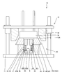
- FIG. 10 is a block diagram showing the rotor manufacturing apparatus 10, and shows a state before forming the upper surface portion 24 of the rotor cover 22. As shown in FIG.
- the rotor manufacturing apparatus 10 is a hydraulic press that forms the upper surface portion 24 of the rotor cover 22 by the slide portion 12 driven in a substantially vertical direction by hydraulic pressure pressing the mold portion 40. is there.
- the rotor manufacturing device 10 may be another hydraulic pressing device or a mechanical pressing device.
- the rotor manufacturing apparatus 10 may be a press device driven by air pressure.
- the rotor manufacturing apparatus 10 includes a bolster 11 provided substantially horizontally, a slide portion 12 vertically moved along the substantially vertical direction with respect to the bolster 11, and a position of the rotor cover 22 mounted on the bolster 11 by movement of the slide portion 12. And a mold portion 40 forming the upper surface portion 24.
- the slide portion 12 is driven along a substantially vertical direction (vertical direction in FIG. 10) with respect to the bolster 11 by a drive mechanism (not shown) for transmitting hydraulic pressure as a power source.
- the slide portion 12 is formed in an annular shape with a curved slide tapered surface 13A whose diameter increases as it goes downward and is formed in an annular shape, and has a slide contact portion 13 that abuts on the mold portion 40.
- the slide portion 12 is moved downward by the drive mechanism, and the mold portion 40 is pressed through the slide contact portion 13, whereby the upper surface portion 24 of the rotor cover 22 is formed.
- the mold portion 40 forms the upper surface portion 24 by pressing the axial direction end portion of the rotor cover 22 radially inward toward the outer mold 41 as a restricting member mounted on the bolster 11 and accommodating the rotor cover 22.
- a lower die 44 mounted on the bolster 11 and on which the rotor cover 22 is mounted.
- the outer mold 41 is a cylindrical member whose inner diameter is set to be substantially equal to the outer diameter of the cylindrical portion 23 of the rotor cover 22, and the cylindrical portion 23 of the rotor cover 22 bulges radially outward when the rotor cover 22 described later is pushed. Regulate the release.
- the first outer collet 42 is used in the first pressing step of the rotor manufacturing method described later, and the second outer collet 52 is used in the second pressing step described later.
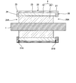
- the first outer collet 42 and the second outer collet 52 differ only in radial thickness. For this reason, in FIG.10 and FIG.11, only the 1st outer side collet 42 is shown in figure, and the 2nd outer side collet 52 is shown with the code
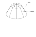
- the first and second outer collets 42 and 52 are circumferentially divided and annularly arranged and placed on the outer mold 41. As shown in FIG. 11, the outer peripheries of the first and second outer collets 42 and 52 are formed as curved outer tapered surfaces 42A and 52A inclined from the central axis such that the outer diameter increases toward the lower part. .
- the first and second outer collets 42 and 52 are formed in a truncated cone shape in a state where the adjacent first and second outer collets 42 and 52 are in contact with each other.
- the downward movement of the slide portion 12 causes the slide contact portion 13 to press the outer tapered surfaces 42A and 52A of the first and second outer collets 42 and 52 downward toward the rotor core 20 in FIG.
- the first and second outer collets 42 and 52 move radially inward at the top of the outer die 41.
- the first and second outer collets 42 and 52 press the axial end of the rotor cover 22 radially inward.
- the outer circumferential surfaces of the plurality of first and second outer collets 42 and 52 may not be curved surfaces, but may be formed as flat pressing taper planes.
- the inner collet 43 is circumferentially divided and annularly arranged, and is provided on the upper portion of the rotor core 20 housed in the rotor cover 22 (see FIG. 15).
- the inner collet 43 holds the rotor cover 22 with the first outer collet 42 by pressing the inner periphery of the axial end of the rotor cover 22 radially outward.
- the lower die 44 is formed to have an outer diameter substantially the same as the inner diameter of the outer die 41, and is accommodated inside the outer die 41.
- the lower die 44 has a disk-like base 45 and an annular abutment 46 projecting axially from the base 45 toward the rotor cover 22 and abutting on the bottom 26 of the rotor cover 22.
- the contact portion 46 supports the other end surface of the permanent magnet 21 via the bottom portion 26 of the rotor cover 22. As shown in FIG. 10, the contact portion 46 has an inner diameter larger than the outer diameter of the protrusion 20B of the rotor core 20, and opposes the other end surface of the permanent magnet 21 with the bottom portion 26 interposed therebetween. An inner space facing the rotor core 20 is provided inside the contact portion 46 with the bottom portion 26 of the rotor cover 22 interposed therebetween.
- the lower mold 44 when the first and second outer collets 42 and 52 move radially inward to press the axial end of the rotor cover 22, the lower mold 44 receives the permanent magnet 21 via the bottom 26 of the rotor cover 22. Support the other end face. For this reason, the upper surface portion 24 of the rotor cover 22, the permanent magnet 21, and the bottom portion 26 of the rotor cover 22 are axially held by a predetermined force by the first and second outer collets 42 and 52 and the lower mold 44.
- the lower mold 44 may not have the base 45, and may be formed in a cylindrical shape having only the contact portion 46.
- the rotor manufacturing apparatus 10 further includes a pressing assisting member 14 which defines the axial position of the first and second outer collets 42 and 52 with respect to the rotor core 20, as shown in FIG.
- the pressing assisting member 14 is provided so as to be vertically movable with respect to the bolster 11, and abuts on the upper surfaces of the first and second outer collets 42 and 52 so that the axes of the first and second outer collet 42 or 52 with respect to the rotor core 20 Define the position of the direction.
- the pressing assisting member 14 is capable of moving up and down relative to the bolster 11 independently of the slide portion 12.
- the pressing assisting member 14 is a disk-like member that contacts all of the upper surfaces of the plurality of first and second outer collets 42 and 52.
- the first and second outer collets 42, 52 are axially displaced from the rotor core 20 when the rotor cover 22 is pushed radially inward by the pressing assisting member 14 coming into contact with the upper surfaces of the first and second outer collets 42, 52. Lifting away in the direction is prevented.
- the pressing assisting member 14 is a reaction force from the rotor cover 22 acting on the first and second outer collets 42 and 52 when the first and second outer collets 42 and 52 press the rotor cover 22 radially inward. May be merely supported, or the first outer collet 42 may be actively pushed downward in the axial direction against the reaction force from the rotor cover 22. In any case, the pressing assisting member 14 defines the axial position of the first outer collet 42 with respect to the rotor core 20.
- the outer tapered surfaces 42A and 52A of the first and second outer collets 42 and 52 are not shown in FIGS. 15, 16, 18, 20 and 21, respectively.
- the case where the axial direction length of the rotor core 20 and the axial direction length of the permanent magnet 21 are the same is demonstrated to an example first.
- the plurality of permanent magnets 21 are attached to the outer peripheral surface of the rotor core 20 to form the rotor core unit 4.
- the permanent magnet 21 is attached between adjacent projections 20B of the rotor core 20 using an adhesive or the like.
- the permanent magnets 21 are arranged at equal intervals in the circumferential direction of the rotor core 20.
- the rotor core unit 4 is inserted from the open end of the rotor cover 22 and accommodated in the rotor cover 22. Since the upper surface portion 24 is not yet formed at this stage, when the rotor core unit 4 is inserted until it abuts on the bottom portion 26 of the rotor cover 22, the open end of the rotor cover 22 is from the upper end of the rotor core 20 as shown in FIG. It will be located above.
- the rotor cover 22 accommodating the rotor core unit 4 is put into the outer mold 41 from the bottom portion 26 side and mounted on the lower mold 44.
- the rotor cover 22 may be accommodated inside the outer mold and placed on the lower die 44, and then the rotor core unit 4 may be inserted from the open end of the rotor cover 22 and accommodated inside the rotor cover 22.
- a pressing step of pressing the opening end of the rotor cover 22 axially protruding from the end of the rotor core 20 radially inward is performed.
- the rotor cover 22 is formed with an upper surface portion 24 and a bottom portion 26 which sandwich the rotor core unit 4 in the axial direction.
- the opening end of the rotor cover 22 is pressed radially inward by the pressing member while the bottom portion 26 of the rotor cover 22 is sandwiched between the lower mold 44 and the permanent magnet 21.
- the open end of the rotor cover 22 is pressed radially inward by the plurality of outer collets as the pressing member and the plurality of inner collets as the holding member.
- a first outer collet 42 and an inner collet 43 as an outer collet are used.
- the second outer collet 52 is used as the outer collet.
- the inner collet 43 is not used in the second pressing step, but the present invention is not limited to this, and an inner collet may be used.
- first outer collets 42 divided in the circumferential direction are arranged annularly at the top of the outer mold 41.
- the first outer collet 42 is arranged to abut on the outer peripheral surface of the opening end of the rotor cover 22 with a predetermined gap in the circumferential direction.
- the first outer collet 42 is disposed such that a circumferential gap faces the gap between the permanent magnets 21 with the rotor cover 22 interposed therebetween (see FIG. 16).
- a plurality of inner collets 43 divided in the circumferential direction are arranged annularly on the inner peripheral side of the rotor cover 22 above the rotor core 20.
- Each inner collet 43 is arranged to abut on the inner peripheral surface of the open end of the rotor cover 22 with a predetermined gap in the circumferential direction.
- the inner collet 43 is disposed such that the circumferential gap is circumferentially offset from the gap between the first outer collet 42.
- the first outer collet 42 is pressed radially inward.
- the radially inward pressing force acting on the first outer collet 42 is set to be greater than the radially outward pressing force acting on the inner collet 43.
- the radially inward pushed portion of the rotor cover 22 may only be pulled radially inward by the first outer collet 42 and the inner collet 43, or may be stretched like a drawing process. Whether to draw or stretch is adjusted by the relationship between the pressing force of the first outer collet 42 and the inner collet 43. In other words, even if the pressing force of the first outer collet 42 and the inner collet 43 is applied to the rotor cover 22 as a crease pressing force, the open end of the rotor cover 22 is bent so as not to change the plate thickness radially inward. Alternatively, the thickness of the rotor cover 22 may be actively reduced by the pressing force of the first outer collet 42 and the inner collet 43. The portions of the rotor cover 22 that are pushed radially inward during pulling or stretching may or may not be wrinkled.
- the first outer collet 42 also presses axially downward.
- the downward pressing in the axial direction by the first outer collet 42 is performed by the application of an external force by the weight of the first outer collet 42 or the pressing assisting member 14.
- the first outer collet 42 presses the rotor cover 22 radially inward and axially downward, as shown in FIG. 17, the upper surface 24 of the rotor cover 22, the permanent magnet 21, and the bottom 26 of the rotor cover 22 It is clamped by the outer collet 42 and the lower mold 44. That is, in the first pressing step, the gap between the first outer collet 42 and the inner collet 43 is reduced at the open end of the rotor cover 22 while the bottom 26 of the rotor cover 22 is sandwiched between the lower mold 44 and the permanent magnet 21. Push radially inward (see FIG. 18). Thus, the open end of the rotor cover 22 is pressed radially inward from the cylindrical portion 23.
- the rotor cover 22 has a part of the upper surface 24, a boss 28 having an outer diameter smaller than that of the cylindrical part 23, and one axial end face of the permanent magnet 21.
- An upper surface corner 25 is formed in contact with the outer peripheral edge 21A.
- the rotor core unit 4 is held by the upper surface corner 25 and the bottom 26.
- the second outer collet 52 is disposed on the outer peripheral side of the boss portion 28 which is the opening end of the rotor cover 22.
- the second outer collet 52 is disposed such that the circumferential gap is offset from the gap between the permanent magnets 21 in the circumferential direction.
- the second outer collet 52 is pressed radially inward. Also in this case, as in the first pressing step, the portion pushed inward in the radial direction of the rotor cover 22 may only be pulled inward in the radial direction by the second outer collet 52, or the drawing process It may be stretched as follows.
- the second outer collet 52 In addition to pressing the rotor cover 22 radially inward, the second outer collet 52 also presses axially downward. Thereby, the spring back when the upper surface part 24 is completed can be reduced. Similarly to the first pressing step, the downward pressing in the axial direction by the second outer collet 52 is performed by the application of an external force by the weight of the second outer collet 52 or the pressing assisting member 14.
- the bosses 28 of the rotor cover 22 are pushed radially inward so that the respective gaps of the second outer collet 52 disappear, as shown in FIG.
- the bosses 28 of the rotor cover 22 are further pushed radially inward as shown in FIG. 22, and the upper surface 24 is formed on the rotor cover 22.
- the rotor core unit 4 is axially held by the whole of the upper surface 24 including the upper surface corner 25 and the bottom 26.
- the pressing process in the case where the axial length of the rotor core 20 is longer than the axial length of the permanent magnet 21 will be described.
- the axial length of the rotor core 20 is longer than the axial length of the permanent magnet 21, in addition to the upper surface portion 24 having the upper surface corner 25, the core contact portion 120 and the core contact that contact the bottom surface of the rotor core 20
- the inner side in the axial direction is recessed along the shape of the bottom portion 26 having the connection portion 121 connecting the portion 120 and the bottom corner portion 27 and the one end portion in the axial direction of the projecting portion 20C of the rotor core 20 and covers one end portion of the rotor core 20
- the recess 122 is formed in the pressing step.
- FIGS. 23 to 26 are diagrams showing a pressing process in the case where the axial length of the rotor core 20 is longer than the axial length of the permanent magnet 21.
- FIG. FIG. 23 is a view before the upper surface portion 24 is formed by the pressing process, and illustrates a cross section (corresponding to the cross section AA in FIG. 1) including only the central portion 20A of the rotor core 20.
- 24 and 25 are views showing a first pressing step.
- FIG. 24 shows a cross section (corresponding to the AA cross section of FIG. 1) including only the central part 20A of the rotor core 20, and
- FIG. 25 shows a cross section including the central part 20A of the rotor core 20 and the projection 20B (B- of FIG. (Corresponding to the B cross section).
- FIG. 24 shows a cross section (corresponding to the AA cross section of FIG. 1) including only the central part 20A of the rotor core 20
- FIG. 25 shows a cross section including the central part 20A of the rotor core 20
- FIG. 26 is a view showing a second pressing step, and illustrates a cross section (corresponding to a cross section taken along line AA in FIG. 1) including only the central portion 20A of the rotor core 20.
- FIG. 23, FIG. 24, and FIG. 26, the protrusion 20B of the rotor core 20 is schematically shown by a broken line.
- FIG. 25 the central portion 20A of the rotor core 20 and the permanent magnet 21 are schematically shown by broken lines.
- FIG. 1 When the axial length of the rotor core 20 is longer than the axial length of the permanent magnet 21, when the rotor core 20 to which the permanent magnet 21 is attached is accommodated in the rotor cover 22 before the upper surface portion 24 is formed, FIG. An axial gap 60 is formed between the permanent magnet 21 and the bottom 26 of the rotor cover 22 as shown in FIG.
- the first outer collet 42 presses the rotor cover 22 axially downward and radially inward as shown by the broken line arrow in FIG. 24, thereby forming a cylinder as shown by the solid line arrow in FIG.
- the portion 23 is pulled upward, and a part of the bottom portion 26 in the rotor cover 22 that abuts on the contact portion 46 of the lower mold 44 is sandwiched and deformed by the permanent magnet 21 and the contact portion 46.
- a part of the outer peripheral side of the bottom portion 26 of the rotor cover 22 in contact with the contact portion 46 is deformed to eliminate the axial gap 60 between the permanent magnet 21 and the bottom surface of the permanent magnet 21. Abut on.
- the upper surface 24, the bottom 26 and the permanent magnet 21 of the rotor cover 22 are held by the first outer collet 42 and the lower die 44.
- the contact portion 46 of the lower die 44 can easily deform a part of the outer peripheral side of the bottom portion 26 of the rotor cover 22, the processing force for deforming the rotor cover 22 can be suppressed.
- the bottom portion 26 of the rotor cover 22 on the center side deforms along one axial end portion of the protrusion 20B of the rotor core 20, that is, along the outer peripheral edge of the protrusion 20C.
- the core contact portion 120 contacting the rotor core 20, the recess 122 along the outer peripheral edge of the protrusion 20C, and the connection portion 121 connecting the core contact portion 120 and the bottom corner 27 are formed.
- the bosses 28 formed in the first pressing step are further pressed radially inward, and the upper surface portion 24 is formed.
- the upper surface corner 25 that contacts the outer peripheral edge 21 A at one axial end surface of the permanent magnet 21 in the pressing step.
- the upper surface portion 24 including the core contact portion 120, the connection portion 121, and the concave portion 122 are further formed.
- the permanent magnet 21 is attached as in the case where the axial lengths of the rotor core 20 and the permanent magnet 21 are the same.
- the bottom portion 26 of the rotor cover 22 contacts the permanent magnet 21. That is, since the axial gap 60 is not formed between the bottom 26 of the rotor cover 22 and the permanent magnet 21, the rotor cover 22 is not deformed in the first pressing step without causing the bottom 26 and the bottom 26 of the rotor cover 22 to deform.
- the upper surface 24, the bottom 26, and the permanent magnet 21 are securely held by the first outer collet and the lower die 44. Thereby, the first holding portion and the second holding portion for holding the rotor core unit 4 in the axial direction, that is, the upper surface portion 24 including the upper surface corner portion 25 and the bottom portion 26 are reliably formed.
- the outer peripheral edge of the permanent magnet 21 in the axial direction one end face of the rotor cover 22 regardless of the magnitude relationship between the axial lengths of the rotor core 20 and the permanent magnet 21.
- the rotor core unit 4 is axially oriented by the top surface portion 24 and the bottom portion 26. It can be held securely. Therefore, regardless of the magnitude relation between the axial lengths of the rotor core 20 and the permanent magnets 21, the rotation of the rotor cover 22 can be prevented.
- an extra material portion 29 separated from the outer peripheral edge portion 21B of the permanent magnet 21 is on the bottom portion 26 of the rotor cover 22. It may be provided. Since the rotor cover 22 before the pressing step has the remaining material portion 29, when forming the upper surface portion 24 in the pressing step, the radial length of the upper surface portion 24 of the rotor cover 22 is suppressed while suppressing a reduction in thickness. To ensure that the permanent magnet 21 is covered.
- the rotor cover is formed so that the axial gap 60 is eliminated by the contact portion 46 of the lower die 44 even in the case where the surplus material portion 29 is provided.
- a rotor cover 22 as shown in FIG. 24 can be formed. Therefore, even in the case where the surplus material portion 29 is provided, the rotor core unit 4 can be axially held by the upper surface portion 24 and the bottom portion 26 to prevent the rotor cover 22 from rotating.
- the rotor core unit 4 when the axial length of the rotor core 20 is longer than the axial length of the permanent magnet 21, the rotor core unit 4 is accommodated in the rotor cover 22 so that the projecting portion 20C faces the bottom portion 26 Explained. Instead of this, the rotor core unit 4 is placed on the rotor cover 22 so that the protrusion 20C is positioned upward before the formation of the upper surface 24, that is, opposed to the opening end of the rotor cover 22 before the formation of the upper surface 24. You may store it. Even in this case, by pressing the end of the rotor cover 22 radially inward in the first pressing step, the upper surface corner 25 in contact with the outer peripheral edge 21A at one axial end face of the permanent magnet 21 is assured Is formed.
- the rotor core is formed by the upper surface 24 having the upper surface corner 25 in contact with the outer peripheral edge 21 A at one axial end face of the permanent magnet 21 and the bottom 26 in contact with at least one of the rotor core 20 and the other end face of the permanent magnet 21. Since the unit 4 is held in the axial direction, the circumferential relative rotation between the rotor core unit 4 and the rotor cover 22 is restricted by the frictional force between them. Therefore, the rotation of the rotor cover 22 can be easily prevented.
- the bottom portion 26 of the rotor cover 22 in the rotor 2 is provided with a recess 122 which is formed along the shape of one end of the protrusion 20B constituting the protrusion 20C and covers the one end.
- a part of the protrusion 20B constituting the protrusion 20C of the rotor core 20 is accommodated in the recess 122 of the rotor cover 22, whereby the protrusion 20B is engaged with the recess 122 and the circumferential direction between the rotor core 20 and the rotor cover 22 Relative rotation is restricted.
- the upper surface corner 25 that contacts the outer peripheral edge 21A at one axial end face of the permanent magnet 21 is formed on the rotor cover 22 in contact with at least one of the upper surface 24 and the rotor core 20 and the other end surface of the permanent magnet 21 to hold the rotor core unit 4 in the axial direction together with the upper surface 24. Therefore, according to the rotor manufacturing method according to the present embodiment, the rotor 2 having the rotor cover 22 locked by the same manufacturing method regardless of the magnitude relation between the axial length of the rotor core 20 and the permanent magnet 21 is obtained. It can be manufactured.
- the first and second outer collets 42 and 52 press the opening end of the rotor cover 22 radially inward while pressing the rotor collet 20 axially toward the rotor core 20.
- the permanent magnet 21 and the rotor cover 22 can be reliably held by the first and second outer collets 42 and 52 and the lower die 44. Therefore, the upper surface portion 24 and the bottom portion 26 which sandwich the rotor core unit 4 in the axial direction can be formed more reliably, and the rotation of the rotor cover 22 can be prevented more reliably.
- the rotor core 20 when the axial length of the rotor core 20 is longer than the axial length of the permanent magnet 21, the rotor core 20 in addition to the upper surface 24 and the bottom 26 sandwiching the rotor core unit 4.
- the recessed part 122 which the inner side of an axial direction is depressed is further formed along the outer peripheral edge part in the axial direction one end part of the projection part 20B which comprises the projection part 20C.
- the protruding portion 20B of the rotor core 20 is engaged with the recessed portion 122, and the circumferential relative between the rotor core 20 and the rotor cover 22 is obtained. Rotation is regulated. Therefore, when the axial length of the rotor core 20 is longer than the axial length of the permanent magnet 21, the rotation of the rotor cover 22 can be prevented more reliably.
- the lower die 44 has an annular contact portion 46 that supports one axial end surface of the permanent magnet 21 via the bottom portion 26 of the rotor cover 22. Therefore, even when the axial length of the rotor core 20 is longer than the axial length of the permanent magnet 21, the bottom portion 26 of the rotor core 20 can be reliably held by the permanent magnet 21 and the lower die 44. Therefore, the concave portion 122 can be reliably formed in the bottom portion 26, and the rotation of the rotor cover 22 can be reliably prevented.
- the rotor 2 has a rotor core unit 4 having a rotor core 20 fixed to the shaft 1 integrally rotatably and a plurality of permanent magnets 21 mounted along the circumferential direction of the rotor core 20, and one axial end face of the permanent magnet 21
- the outer periphery of the rotor core 20 has an upper surface 24 in contact with the outer peripheral edge 21A, and a bottom 26 in contact with at least one of the other end surface of the permanent magnet 21 and the rotor core 20 and axially holding the rotor core unit 4 together with the upper surface 24.
- a single cylindrical rotor cover 22 covering the
- the rotor 2 has a projecting portion 20C in which the rotor core 20 projects in the axial direction more than the other end surface of the permanent magnet 21, and a projecting portion is formed on the bottom portion 26 of the rotor cover 22 facing the other end surface of the permanent magnet 21.
- a recess 122 is provided to abut the outer peripheral edge of 20C.
- the rotor core 20 projects from the central portion 20 A provided inside the plurality of permanent magnets 21 radially outward from the central portion 20 A and a plurality of projections provided respectively between the adjacent permanent magnets 21. 20B, and the recess 122 abuts on the outer peripheral edge of the protrusion 20B.
- the protrusion 20B constituting the protrusion 20C of the rotor core 20 is accommodated in the recess 122 of the rotor cover 22. Therefore, the protrusion 20B constituting the protrusion 20C is engaged with the recess 122 and the rotor core unit 4 The relative rotation between the rotor and the rotor cover 22 in the circumferential direction is restricted. Therefore, rotation prevention of the rotor cover 22 can be performed more reliably.
- the rotary electric machine 100 includes a rotor 2 having these configurations.
- the rotor manufacturing method according to the embodiment of the present invention includes a rotor core unit 4 having a rotor core 20 fixed to the shaft 1 integrally rotatably and a plurality of permanent magnets 21 attached along the circumferential direction of the rotor core 20.
- a rotor manufacturing method for manufacturing a rotor 2 comprising the steps of: mounting a cylindrical rotor cover 22 having a bottom 26 on a lower mold 44; storing the rotor core unit 4 inside the rotor cover 22; The outer collet (first outer collet 42, second outer collet 52) of the open end of the rotor cover 22 axially projecting from the end of the rotor core 20 while the bottom 26 of the rotor 22 is sandwiched by the lower mold 44 and the permanent magnet 21 By pressing radially inwards to abut the outer peripheral edge 21A at one end face of the permanent magnet 21 in the axial direction.
- a bottom 26 to which the other end face of the section 24 and the permanent magnet 21 and in contact with at least one of the rotor core 20 to sandwich the rotor core unit 4 together with the upper surface portion 24 in the axial direction comprises a pressing step of forming the rotor cover 22, the.
- the open end of the rotor cover 22 is pressed radially inward by the outer collet (first outer collet 42, second outer collet 52) while the bottom portion 26 of the rotor cover 22 is sandwiched between the lower mold 44 and the permanent magnet 21. Do. Thereby, the upper surface portion 24 and the bottom portion 26 which sandwich the rotor core unit 4 in the axial direction are formed on the rotor cover 22.
- the pressing step of forming the upper surface portion 24 and the bottom portion 26 axially presses the outer collet (first outer collet 42, second outer collet 52) toward the rotor core 20. While pressing the open end of the rotor cover 22 radially inward, the permanent magnet 21 and the rotor cover 22 are axially sandwiched by the outer collet (first outer collet 42, second outer collet 52) and the lower die 44. Form the top 24 and the bottom 26 by pressing.
- the rotor core unit 4 can be easily held by the rotor cover 22 by pressing the outer collet (the first outer collet 42 and the second outer collet 52) in the axial direction, and the upper surface portion 24 and bottom 26 can be easily formed.
- the rotor manufacturing apparatus 10 manufactures a rotor 2 including a rotor core unit 4 having a rotor core 20 fixed to the shaft 1 so as to be integrally rotatable and a plurality of permanent magnets 21 mounted along the circumferential direction of the rotor core 20.
- An outer collet (a first outer collet 42, a second outer collet 52) for pressing the open end of the rotor cover 22 axially projecting from an end of the rotor core 20 radially inward, and a rotor core
- An outer collet (a first outer collet 42, a second outer ring 42, a lower mold 44 having a bottomed cylindrical rotor cover 22 accommodating the unit 4 mounted thereon and sandwiching a bottom portion 26 of the rotor cover 22 with the permanent magnet 21;
- An upper surface portion 2 which is in contact with the outer peripheral edge portion 21A at one end face in the axial direction of the permanent magnet 21 by the two outer collets 52) and the lower die 44.
- the upper surface portion 24 abuts on at least one of the other end face and the rotor core 20 of the permanent magnet 21 and a bottom 26 that sandwich the rotor core unit 4 in the axial direction is formed in the rotor cover 22.
- first outer collet 42, second outer collet 52 pressing the open end of the rotor cover 22 and a lower mold 44 sandwiching the bottom portion 26 of the rotor cover 22 with the permanent magnet 21;
- the rotor cover 22 is formed with an upper surface portion 24 and a bottom portion 26 which sandwich the rotor core unit 4 in the axial direction.
- the lower die 44 is in contact with the bottom portion 26 of the rotor cover 22 to be mounted, and an annular contact for supporting one axial end surface of the permanent magnet 21 via the bottom portion 26 of the rotor cover 22. It has a part 46.
- the bottom portion 26 of the rotor cover 22 can be reliably held between the lower die 44 and the permanent magnet 21. Therefore, the top surface 24 and the bottom 26 can be easily formed, and the rotation of the rotor cover 22 can be prevented more reliably.
- the upper surface portion 24 of the rotor cover 22 extends radially inward until it covers the permanent magnet 21.
- the upper surface portion 24 may extend so that a part of the permanent magnet 21 is exposed.
- the outer die 41 is disposed on the entire outer periphery of the cylindrical portion 23 in forming the upper surface portion 24 of the rotor cover 22.
- the outer die 41 may be disposed in part or not. Good.
- the upper surface portion 24 is gradually formed twice in the first pressing step and the second pressing step.
- the upper end portion 24 may be formed by pressing the open end of the rotor cover 22 radially inward three or more times.
- the bottom corner 27 is formed on the rotor cover 22 in the first pressing step.
- the bottom corner portion 27 may be gradually formed by a plurality of pressing steps, such as forming the first pressing step and the second pressing step twice.
- the upper surface part 24 is formed using the 1st outer side collet 42 and the inner side collet 43 in a 1st press process.
- the upper surface portion 24 may be formed using only the first outer collet 42 without using the inner collet 43 as in the second pressing step.
- the rotor cover 22 has been described as being made of nonmagnetic stainless steel in the above embodiment, it may be made of other nonmagnetic metals such as aluminum.
- the rotor manufacturing apparatus 10 may include an inner auxiliary member (not shown) that defines the axial position of the inner collet 43 with respect to the rotor core 20. Thereby, the floating of the inner collet 43 away from the rotor core 20 in the axial direction is prevented, and the rotor cover 22 can be held by the first outer collet 42 and the inner collet 43 with a stable holding force.
Landscapes
- Engineering & Computer Science (AREA)
- Power Engineering (AREA)
- Manufacturing & Machinery (AREA)
- Permanent Field Magnets Of Synchronous Machinery (AREA)
- Manufacture Of Motors, Generators (AREA)
Abstract
ロータ2は、シャフト1に一体回転可能に固定されるロータコア20とロータコア20の周方向に亘って取り付けられる複数の永久磁石21とを有するロータコアユニット4と、永久磁石21の軸方向の一端面における外周縁部21Aに当接する上面部24と永久磁石21及びロータコア20の少なくとも一方に当接して上面部24と共にロータコアユニット4を軸方向に挟持する底部26とを有しロータコア20の外周を覆う単一の円筒状のロータカバー22と、を備える。
Description
本発明は、ロータ、回転電機、ロータ製造方法、及びロータ製造装置に関する。
JP1999-299149Aには、回転電機に用いられるロータが開示されている。このロータは、マグネットが外周に取り付けられたヨークと、マグネットの外周面を覆うカバーと、を備える。マグネットには周方向端部に切り欠きが設けられ、カバーにはその開口縁部に凹部が設けられる。カバーの凹部が隣接するマグネット間の切り欠きに係止されることで、カバーの軸方向及び周方向の移動が規制される。
上記従来の技術では、ヨークに対するカバーの周方向の固定、すなわちカバーの回り止めを行うため、カバーをマグネットの外周に被せる前にマグネット及びカバーに加工を施す必要がある。このため、製造工程が複雑化する。
本発明は、ロータカバーの回り止めを容易に行うことを目的とする。
本発明のある態様によれば、ロータであって、回転軸に一体回転可能に固定されるロータコアとロータコアの周方向に亘って取り付けられる複数の永久磁石とを有するロータコアユニットと、永久磁石の軸方向の一端面における外周縁部に当接する第一挟持部と永久磁石の他端面及びロータコアの少なくとも一方に当接して第一挟持部と共にロータコアユニットを軸方向に挟持する第二挟持部とを有しロータコアの外周を覆う単一の円筒状のロータカバーと、を備える。
以下、添付図面を参照しながら本発明の実施形態について説明する。
図1は、本実施形態に係るロータ2を備える回転電機100を回転軸に垂直な方向に切断した断面を示す断面図である。
回転電機100は、モータ及び発電機の少なくとも一方として機能する。回転電機100は、図1に示すように、回転可能な回転軸としてのシャフト1と、シャフト1に一体的に固定されるロータ2と、ロータ2の外周側にロータ2と所定の空隙を介して配設されるステータ3と、を備える。
ロータ2は、ロータコアユニット4と、ロータコアユニット4を収容するロータカバー22と、を備える。
ロータコアユニット4は、シャフト1の外周に固定されてシャフト1とともに回転するロータコア20と、ロータコア20の外周面に周方向に亘って等間隔で取り付けられる複数の永久磁石21と、を有する。
ロータコアユニット4は、周方向に並ぶ6個の永久磁石21を有する。ロータコアユニット4は、これに限らず、周方向に並ぶ7個以上の永久磁石21を有していてもよいし、2から5個のいずれかの永久磁石21を有していてもよい。
ロータコア20は、複数の永久磁石21の内側に設けられる中心部20Aと、中心部20Aから径方向外側に突出して形成される複数の突起部20Bと、を有する。シャフト1は、中心部20Aを挿通してロータコア20に固定される。突起部20Bは、周方向に等間隔で複数設けられ、それぞれ隣り合う永久磁石21の間に配置される。言い換えれば、永久磁石21は、ロータコア20の隣り合う突起部20Bの間に配置され、中心部20Aに固定される。
ステータ3は、ロータ2と所定の空隙を介してロータ2を取り囲むように配設される円環状のステータコア31と、ステータコア31に巻装される巻線32と、を備える。
ステータコア31は、環状のヨーク部33と、ヨーク部33から径方向内側に向けて突設され周方向に所定の間隔で配置される複数のティース34と、隣接するティース34によってヨーク部33の内周側に画成されるスロット35と、を有する。
巻線32は、ステータコア31のティース34に巻回され、各ティース34にはコイルが形成される。巻線32の端末は、ステータ3に設けられる電極(図示せず)に接続される。電極を介してコイルに電力が供給されるとステータコア31が磁化し、ロータコアユニット4の永久磁石21との作用によってロータ2がシャフト1を軸として回転する。
図2は、本実施形態におけるロータ2を示す斜視図である。図3は、図1におけるA-A線に沿ったシャフト1及びロータ2の断面図である。
ロータカバー22は、ロータコア20及びロータコア20に取り付けられる永久磁石21を有するロータコアユニット4を収容する非磁性のステンレス鋼から成る有底筒状に形成される。ロータカバー22は、図3に示すように、ロータコア20の外周を覆う円筒状の円筒部23と、円筒部23の軸方向一方側(図3中左側)に設けられ円筒部23から折り曲げられて形成される第一挟持部としての上面部24と、円筒部23の軸方向他方側(図3中右側)に設けられる第二挟持部としての底部26と、を有する。ロータカバー22は、単一の部材を加工することによって形成されるものであり、円筒部23、上面部24、及び底部26は一体的に形成される。
上面部24は、軸方向に垂直な面を有すると共に中央にシャフト1より大径の孔24Aを有する円環状に形成される。上面部24は、円筒部23の一端部との間に形成され、永久磁石21の軸方向の一端面における外周縁部21Aに当接する上面角部25を外周端部に有する。
底部26は、図3に示すように、軸方向に垂直な面を有するとともに中央にシャフト1より大径の孔26Aを有する円環状に形成される。底部26は、永久磁石21の他端面に対向し、ロータコアユニット4におけるロータコア20及び永久磁石21の少なくとも一方の他端部に当接する。底部26は、円筒部23の他端部との間に形成される底部角部27を外周端部に有する。底部26の具体的な構成は、後に詳しく説明する。
上面部24は、円筒部23の軸方向一方側(図3中左側)の端部を径方向内側に押圧して形成される。これにより、上面角部25が永久磁石21の一端面における外周縁部21Aに当接するように形成される。ロータコアユニット4は、永久磁石21の一端面における外周縁部21Aに当接する上面部24の上面角部25と、ロータコア20及び永久磁石21の少なくとも一方の他端部に当接する底部26とによって、所定の力で軸方向に挟持される。これにより、ロータカバー22とロータコアユニット4との間の摩擦力が大きくなり、摩擦力によってロータカバー22とロータコアユニット4との周方向の相対回転が規制される。
なお、上面角部25は、永久磁石21の軸方向一端面における外周縁部21Aの全周のうちの一部に当接していればよい。また、上面部24は、より確実にロータカバー22を回り止めするためにはロータコア20及び永久磁石21の軸方向一方側の端面に当接して摩擦力を増大させることが望ましいが、少なくとも上面角部25が外周縁部21Aに当接していればよい。つまり、上面部24における上面角部25以外の部分がロータコアユニット4との間に隙間を持って形成されてもよい。
上面部24の孔24A及び底部26の孔26Aはロータコア20の中心部20Aの外径よりも小径に形成される。上面部24及び底部26は、永久磁石21の軸方向両端面を覆い隠すように延びて形成される。
次に、上面角部25、底部26、及び底部角部27について詳しく説明する。
ロータコア20及び永久磁石21を同一の軸方向長さで形成しようとしても、それぞれ寸法公差の範囲内で軸方向長さにばらつきが生じ、ロータコア20と永久磁石21との軸方向長さが互いに異なることがある。
これに対し、ロータコア20の軸方向長さが永久磁石21の軸方向長さよりも長い場合、短い場合、及び互いに同一の場合のいずれの場合であっても、永久磁石21の外周縁部21Aに当接する上面角部25を有する上面部24と永久磁石21の他端面及びロータコア20の少なくとも一方に当接する底部26とがロータカバー22に形成される。このため、ロータ2では、ロータコアユニット4とロータカバー22との周方向の相対回転を規制することができる。言い換えれば、上面部24と底部26とによってロータコアユニット4を軸方向に挟持することにより、ロータコア20と永久磁石21の軸方向長さの大小関係に関わらず、ロータカバー22の回り止めを行うことができる。
図4は、ロータコア20の軸方向長さが永久磁石21の軸方向長さよりも長い場合において、図1におけるA-A線に沿った断面を示す断面図である。図4に示すように、ロータコア20の軸方向長さが永久磁石21の軸方向長さよりも長い場合には、ロータコア20は、永久磁石21の他端面よりも軸方向に突出する突出部20Cを有する。突出部20Cは、永久磁石21の他端面よりも軸方向に突出する中心部20Aの一部及び突起部20Bの一部によって構成される。ロータカバー22の底部26は、ロータコア20の底面(突出部20Cの端面)に当接するコア当接部120と、コア当接部120と底部角部27とを接続する接続部121と、を有する。
接続部121は、図4に示すように、ロータコア20の外周面と永久磁石21の軸方向他端面とに当接するものでもよいし、図5に示すように離間するものでもよい。いずれの場合にも、上面角部25が永久磁石21の軸方向一端面における外周縁部21Aに当接し、底部26が少なくともロータコア20の突出部20Cに当接することによりロータコアユニット4が軸方向に挟持されるため、ロータカバー22の回り止めを行うことができる。なお、図4に示すように、接続部121がロータコア20の外周面と永久磁石21の軸方向他端面とに当接する場合及び底部角部27が永久磁石21の他端面の外周縁部21B当接する場合には、それぞれ摩擦力が増大しロータカバー22の回り止めをより確実に行うことができる。
図6は、図3におけるC矢視図であり、ロータカバー22の底部26を示す平面図である。ロータコア20の軸方向長さが永久磁石21の軸方向長さよりも長い場合には、図6に示すように、ロータコア20の突出部20Cを構成する突起部20Bの一部を覆う凹部122がロータカバー22の底部26に設けられる。
図7は、図6におけるD-D線に沿った断面図である。図7では、ロータコア20における突起部20Bと中心部20Aとの境界を模式的に破線で表す。図8は、図6におけるE-E線に沿った断面図である。
図7及び図8に示すように、凹部122は、突出部20Cの端部における外周縁部に沿って軸方向の内側(ロータカバー22の内側)が窪んで形成される。これにより、突出部20Cを構成する突起部20Bの一部が凹部122に係止されてロータコア20とロータカバー22との周方向(図8中左右方向)の相対回転が規制される。このように、ロータコア20の軸方向長さが永久磁石21の軸方向長さよりも長い場合には、上面部24の上面角部25と底部26とによってロータコアユニット4が挟持されることに加え、凹部122によって突出部20Cが係止される。したがって、ロータカバー22の回り止めをより確実に行うことができる。
ロータコア20の軸方向長さが永久磁石21の軸方向長さよりも短い場合(図9参照)及び互いの長さが同一の場合(図2参照)では、ロータカバー22の底部26に凹部122は形成されない。図9に示すように、ロータコア20の軸方向長さが永久磁石21の軸方向長さよりも短い場合には、ロータカバー22の底部26は、永久磁石21の他端面に当接し、ロータコア20とは離間する環状の平面として形成される。この場合には、底部26は、永久磁石21の端面に当接することに加え底部角部27が永久磁石21の他端面における外周縁部21Bに当接して、上面角部25と共にロータコアユニット4を挟持する。
図2に示すように、ロータコア20と永久磁石21の軸方向長さが同一の場合には、ロータカバー22の底部26は、永久磁石21及びロータコア20の両方に当接する環状の平面として形成される。この場合には、底部26は、永久磁石21及びロータコア20の両方に当接すると共に底部角部27が永久磁石21の他端面における外周縁部21Bに当接して、上面角部25と共にロータコアユニット4を挟持する。
次に、主に図10及び図11を参照して、ロータ2を製造するロータ製造装置10について説明する。図10は、ロータ製造装置10を示す構成図であり、ロータカバー22の上面部24を形成する前の状態を示す図である。
ロータ製造装置10は、図10に示すように、油圧によって略鉛直方向に駆動されるスライド部12が金型部40を押圧することにより、ロータカバー22の上面部24を形成する油圧プレス装置である。ロータ製造装置10は、他の液圧プレス装置でもよく、機械プレス装置でもよい。また、ロータ製造装置10は、空気圧によって駆動されるプレス装置でもよい。
ロータ製造装置10は、略水平に設けられるボルスタ11と、ボルスタ11に対して略鉛直方向に沿って上下動するスライド部12と、ボルスタ11に載置されスライド部12の移動によってロータカバー22の上面部24を形成する金型部40と、を備える。
スライド部12は、動力源としての油圧を伝達する駆動機構(図示省略)により、ボルスタ11に対して略鉛直方向(図10中上下方向)に沿って駆動される。スライド部12は、下方に向かうにつれて径が大きくなる曲面状のスライドテーパ面13Aを内側に有して環状に形成されると共に金型部40に当接するスライド当接部13を有する。駆動機構によりスライド部12が下方に移動し、スライド当接部13を介して金型部40が押圧されることにより、ロータカバー22の上面部24が形成される。
金型部40は、ボルスタ11に載置されロータカバー22を収容する規制部材としての外型41と、ロータカバー22における軸方向端部を径方向内側へ向けて押圧して上面部24を形成する押圧部材としての複数の外側コレットと、ロータカバー22の軸方向端部の内周を径方向外側へ向けて押圧して保持する保持部材としての複数の内側コレット43と、外型41の内側に収容されてボルスタ11に載置されると共にロータカバー22が載置する下型44と、を備える。
外型41は、内径がロータカバー22の円筒部23の外径とほぼ等しく設定された円筒状部材であり、後述するロータカバー22の押し込み時にロータカバー22の円筒部23が径方向外側に膨出することを規制する。
外側コレットとしては、後述するロータ製造方法の第一押圧工程では第一外側コレット42が用いられ、後述する第二押圧工程では第二外側コレット52が用いられる。第一外側コレット42と第二外側コレット52とは、径方向の厚さのみが異なる。このため、図10及び図11では、第一外側コレット42のみを図示し、第二外側コレット52は括弧内の符号で示す。
第一、第二外側コレット42,52は、周方向に分割され環状に並べられて外型41に載置される。図11に示すように、第一、第二外側コレット42,52の外周は、下部に向かうにつれて外径が大きくなるように中心軸から傾斜する曲面状の外側テーパ面42A,52Aとして形成される。各第一、第二外側コレット42,52は、隣り合う第一、第二外側コレット42,52が互いに当接した状態で円錐台形状になるように形成される。
スライド部12の下方への移動により、スライド当接部13によって第一、第二外側コレット42,52の外側テーパ面42A,52Aがロータコア20へ向かって図10中下方へ押圧される。これにより、第一,第二外側コレット42,52は、外型41の上部において径方向内側へ向かって移動する。よって、第一、第二外側コレット42,52は、ロータカバー22における軸方向端部を径方向内側へ向けて押圧する。なお、複数の第一、第二外側コレット42,52の外周面は、曲面ではなく、それぞれ平面状の押圧テーパ平面として形成されてもよい。
内側コレット43は、周方向に分割されて環状に並べられて、ロータカバー22に収容されたロータコア20の上部に設けられる(図15参照)。内側コレット43は、ロータカバー22の軸方向端部の内周を径方向外側へ向けて押圧することにより、第一外側コレット42との間でロータカバー22を保持する。
下型44は、外径が外型41の内径と略同一に形成され、外型41の内側に収容される。下型44は、円盤状の基部45と、基部45からロータカバー22に向かって軸方向に突出すると共にロータカバー22の底部26に当接する環状の当接部46と、を有する。
当接部46は、ロータカバー22の底部26を介して永久磁石21の他端面を支持する。当接部46は、図10に示すように、ロータコア20の突起部20Bの外径よりも大きな内径を有し底部26を挟んで永久磁石21の他端面に対向する。当接部46の内側には、ロータカバー22の底部26を挟んでロータコア20に対向する内側空間が設けられる。
下型44は、第一、第二外側コレット42,52が径方向内側に移動してロータカバー22の軸方向端部を押圧する際に、ロータカバー22の底部26を介して永久磁石21の他端面を支持する。このため、第一、第二外側コレット42,52と下型44とにより、ロータカバー22の上面部24、永久磁石21、ロータカバー22の底部26が所定の力により軸方向に挟持される。なお、下型44は、基部45を有していなくてもよく、当接部46のみを有する筒状に形成されてもよい。
ロータ製造装置10は、図10に示すように、ロータコア20に対する第一、第二外側コレット42,52の軸方向の位置を規定する押圧補助部材14をさらに備える。
押圧補助部材14は、ボルスタ11に対して上下動可能に設けられ、第一、第二外側コレット42,52の上面に当接することによりロータコア20に対する第一、第二外側コレット42,52の軸方向の位置を規定する。押圧補助部材14は、スライド部12とは連動せず、独立してボルスタ11に対して上下動可能である。押圧補助部材14は、複数の第一、第二外側コレット42,52における上面の全てに当接する円盤状部材である。押圧補助部材14が第一、第二外側コレット42,52の上面に当接することにより、ロータカバー22を径方向内側に押し込む際に、第一、第二外側コレット42,52がロータコア20から軸方向に離れて浮き上がることが防止される。
押圧補助部材14は、第一、第二外側コレット42,52がロータカバー22を径方向内側に押圧する際に、第一、第二外側コレット42,52に作用するロータカバー22からの反力を単に支持するのみでもよいし、ロータカバー22からの反力に抗して第一外側コレット42を軸方向下方に積極的に押圧してもよい。いずれの場合であっても、押圧補助部材14は、ロータコア20に対する第一外側コレット42の軸方向の位置を規定する。
次に、ロータ2の製造方法について図12~図26を参照しながら説明する。なお、図15、図16、図18、図20、及び図21では、第一、第二外側コレット42,52における外側テーパ面42A,52Aの図示を省略する。以下では、まず、ロータコア20の軸方向長さと永久磁石21の軸方向長さが同一である場合を例に説明する。
初めに、ロータコア20の外周面に複数の永久磁石21を取り付けてロータコアユニット4を形成する。永久磁石21は、ロータコア20の隣り合う突起部20Bの間に接着剤などを用いて取り付けられる。これにより、永久磁石21は、ロータコア20の周方向に亘って等間隔に配置される。
続いて、図12に示すように、ロータカバー22の開口端から、ロータコアユニット4を入れてロータカバー22内に収容する。この段階ではまだ上面部24が形成されていないので、ロータコアユニット4をロータカバー22の底部26に当接するまで入れると、図13に示すように、ロータカバー22の開口端はロータコア20の上端より上方に位置することになる。
続いて、図14に示すように、ロータコアユニット4が収容されたロータカバー22を底部26側から外型41に入れて下型44に載置する。なお、先にロータカバー22を外型の内側に収容して下型44に載置し、その後ロータコアユニット4をロータカバー22の開口端から入れてロータカバー22の内側に収容してもよい。
続いて、ロータコア20の端部から軸方向に突出するロータカバー22の開口端を径方向内側へ向けて押圧する押圧工程を行う。押圧工程では、ロータコアユニット4を軸方向に挟持する上面部24と底部26とをロータカバー22に形成する。
押圧工程では、ロータカバー22の底部26を下型44と永久磁石21とによって挟みながら、ロータカバー22の開口端を押圧部材によって径方向内側へ向けて押圧する。押圧工程は、押圧部材としての複数の外側コレット及び保持部材としての複数の内側コレットによってロータカバー22の開口端を径方向内側へ向けて押圧する。
押圧工程は、円筒部23の開口端を径方向内側へ向けて押圧する第一押圧工程と、第一押圧工程で径方向内側へ押し込まれたロータカバー22の開口端をさらに径方向内側へ押圧する第二押圧工程と、を含む。第一押圧工程では、外側コレットとしての第一外側コレット42と内側コレット43が使用される。また、第二押圧工程では、外側コレットとして第二外側コレット52が使用される。なお、本実施形態では、第二押圧工程において、内側コレット43は使用されないが、これに限らず、内側コレットを使用してもよい。
第一押圧工程では、まず、図15及び図16に示すように、外型41の上部に周方向に分割された複数の第一外側コレット42を環状に並べて配置する。第一外側コレット42は、周方向に所定の隙間を有した状態でロータカバー22の開口端の外周面に当接するように配置される。第一外側コレット42は、周方向の隙間がロータカバー22を挟んで永久磁石21間の隙間と対向するように配置される(図16参照)。
さらに、図15及び図16に示すように、周方向に分割された複数の内側コレット43をロータコア20の上部であってロータカバー22の内周側に環状に並べて配置する。各内側コレット43は、周方向に所定の隙間を有した状態でロータカバー22の開口端の内周面に当接するように配置される。内側コレット43は、周方向の隙間が第一外側コレット42間の隙間と周方向にずれて配置される。
続いて、内側コレット43を径方向外側に向けて押圧した状態で、第一外側コレット42を径方向内側に向けて押圧する。このとき、第一外側コレット42に作用する径方向内側への押圧力は、内側コレット43に作用する径方向外側への押圧力を上回るように設定される。これにより、第一外側コレット42が径方向内側へ移動し、ロータカバー22の開口端は、内側コレット43によって内周側から保持された状態で第一外側コレット42によって径方向内側へ向けて押し込まれる。
ロータカバー22の径方向内側へ向けて押し込まれる部分は、第一外側コレット42及び内側コレット43によって径方向内側へ引っ張られるだけであってもよいし、引き抜き加工のように引き伸ばされてもよい。引っ張りとするか引き伸ばしとするかは、第一外側コレット42及び内側コレット43の押圧力の関係によって調整される。言い換えれば、第一外側コレット42及び内側コレット43の押圧力がしわ押さえ力としてロータカバー22に付与されながら、ロータカバー22の開口端が径方向内側へ板厚を変化させないように折り曲げられるものでもよいし、第一外側コレット42及び内側コレット43の押圧力によってロータカバー22の板厚を積極的に減少させるものでもよい。引っ張り又は引き伸ばしに際して、ロータカバー22の径方向内側へ向けて押し込まれる部分には、しわが形成されていてもよいし、形成されなくてもよい。
また、第一外側コレット42は、ロータカバー22を径方向内側に向けて押圧するのに加えて軸方向下方にも押圧する。第一外側コレット42による軸方向下方への押圧は、第一外側コレット42の自重又は押圧補助部材14による外力の付加によって行われる。
第一外側コレット42がロータカバー22を径方向内側及び軸方向下方に押圧することにより、図17に示すように、ロータカバー22の上面部24、永久磁石21、ロータカバー22の底部26が第一外側コレット42と下型44とによって挟持される。つまり、第一押圧工程では、ロータカバー22の底部26を下型44と永久磁石21とによって挟みながら、ロータカバー22の開口端を、第一外側コレット42及び内側コレット43の各隙間が減少するように径方向内側に押し込む(図18参照)。このようにして、ロータカバー22の開口端が円筒部23より径方向内側に押圧される。
これにより、図17及び図19に示すように、ロータカバー22には、上面部24の一部と、円筒部23よりも小さな外径を有するボス部28と、永久磁石21の軸方向一端面における外周縁部21Aに当接する上面角部25と、が形成される。上面角部25と底部26とにより、ロータコアユニット4が挟持される。
続いて、第二押圧工程では、図20に示すように、第二外側コレット52をロータカバー22の開口端であるボス部28の外周側に配置する。第二外側コレット52は、周方向の隙間が永久磁石21間の隙間とは周方向にずれて配置される。
続いて、第二外側コレット52を径方向内側に向けて押圧する。この際においても、第一押圧工程と同様に、ロータカバー22の径方向内側へ向けて押し込まれる部分は、第二外側コレット52によって径方向内側へ引っ張られるだけであってもよいし、引き抜き加工のように引き伸ばされてもよい。
また、第二外側コレット52は、ロータカバー22を径方向内側に向けて押圧するのに加えて軸方向下方にも押圧する。これにより、上面部24が完成した際のスプリングバックを低減することができる。第二外側コレット52による軸方向下方への押圧は、第一押圧工程と同様に、第二外側コレット52の自重又は押圧補助部材14による外力の付加によって行われる。
ロータカバー22のボス部28は、図21に示すように、第二外側コレット52の各隙間がなくなるように径方向内側に押し込まれる。これにより、第二外側コレット52を取り除くと、図22に示すように、ロータカバー22のボス部28はさらに径方向内側に押し込まれて、上面部24がロータカバー22に形成される。これにより、上面角部25を含む上面部24の全体と底部26とによって、ロータコアユニット4が軸方向に挟持される。
このような押圧工程が完了すると、外型41を取り外し、ロータコア20の中央にシャフト1を挿入する。これにより、図2に示すように、シャフト1を有するロータ2が完成する。
次に、図23から図26を参照して、ロータコア20の軸方向長さが永久磁石21の軸方向長さよりも長い場合における押圧工程について説明する。ロータコア20の軸方向長さが永久磁石21の軸方向長さよりも長い場合には、上面角部25を有する上面部24に加え、ロータコア20の底面に当接するコア当接部120及びコア当接部120と底部角部27とを接続する接続部121を有する底部26と、ロータコア20の突出部20Cの軸方向の一端部の形状に沿って軸方向の内側が窪みロータコア20の一端部を覆う凹部122と、が押圧工程において形成される。
図23から図26は、ロータコア20の軸方向長さが永久磁石21の軸方向長さよりも長い場合における押圧工程を示す図である。図23は、押圧工程により上面部24が形成される前の状態における図であり、ロータコア20の中心部20Aのみを含む断面(図1のA-A断面に相当)を図示したものである。図24及び図25は第一押圧工程を示す図である。図24はロータコア20の中心部20Aのみを含む断面(図1のA-A断面に相当)を図示し、図25はロータコア20の中心部20A及び突起部20Bを含む断面(図1のB-B断面に相当)を図示したものである。図26は、第二押圧工程を示す図であり、ロータコア20の中心部20Aのみを含む断面(図1のA-A断面に相当)を図示したものである。図23、図24、及び図26では、ロータコア20の突起部20Bを破線で模式的に示す。図25では、ロータコア20の中心部20Aと永久磁石21とを破線で模式的に示す。
ロータコア20の軸方向長さが永久磁石21の軸方向長さよりも長い場合には、永久磁石21が取り付けられたロータコア20を上面部24が形成される前のロータカバー22に収容すると、図23に示すように、永久磁石21とロータカバー22の底部26との間に軸方向隙間60が形成される。
第一押圧工程において、第一外側コレット42が図24中破線矢印で示すように軸方向下方及び径方向内側へ向けてロータカバー22を押圧することにより、図24中実線矢印で示すように円筒部23が上方に引っ張られて、ロータカバー22において下型44の当接部46に当接する底部26の一部は、永久磁石21と当接部46とによって挟み込まれて変形する。具体的には、当接部46に当接するロータカバー22の底部26における外周側の一部は、永久磁石21との間の軸方向隙間60をなくすように変形して、永久磁石21の底面に当接する。よって、ロータカバー22の上面部24、底部26、及び永久磁石21が第一外側コレット42及び下型44によって挟持される。
また、下型44の当接部46により、ロータカバー22の底部26における外周側の一部を容易に変形させることができるため、ロータカバー22を変形させる加工力を抑えることができる。
第一押圧工程では、このようなロータカバー22の底部26における外周側の変形と同時に、中心側のロータカバー22の底部26にも、上方に引っ張られる力が作用する。よって、図25に示すように、中心側のロータカバー22の底部26は、ロータコア20の突起部20Bの軸方向一端部、つまり突出部20Cの外周縁部に沿うように変形する。これにより、ロータコア20に当接するコア当接部120、突出部20Cの外周縁部に沿った凹部122、及びコア当接部120と底部角部27とを接続する接続部121が形成される。
第二押圧工程では、図26に示すように、第一押圧工程で形成されたボス部28がさらに径方向内側に押圧され、上面部24が形成される。
このように、ロータコア20の軸方向長さが永久磁石21の軸方向長さよりも長い場合には、押圧工程において、永久磁石21の軸方向一端面における外周縁部21Aに当接する上面角部25を含む上面部24に加え、コア当接部120、接続部121、及び凹部122がさらに形成される。
一方、ロータコア20の軸方向長さが永久磁石21の軸方向長さよりも短い場合には、ロータコア20と永久磁石21の軸方向長さが同一の場合と同様に、永久磁石21が取り付けられたロータコア20をロータカバー22に収容すると、ロータカバー22の底部26と永久磁石21とが接触する。つまり、ロータカバー22の底部26と永久磁石21との間に軸方向隙間60が形成されないため、第一押圧工程において、底部26とロータカバー22の底部26の変形を伴わずに、ロータカバー22の上面部24、底部26、及び永久磁石21が第一外側コレット及び下型44によって確実に挟持される。これにより、ロータコアユニット4を軸方向に挟持する第一挟持部及び第二挟持部、つまり上面角部25を含む上面部24と底部26とが確実に形成される。
以上のように、本実施形態に係るロータ製造方法では、ロータコア20と永久磁石21の軸方向長さの大小関係によらず、ロータカバー22には、永久磁石21の軸方向一端面における外周縁部21Aに当接する上面角部25を含む上面部24と、ロータコアユニット4におけるロータコア20及び永久磁石21の他端面の少なくとも一方に当接して上面部24との間でロータコアユニット4を軸方向に挟持する底部26と、が形成される。言い換えれば、ロータコア20と永久磁石21との軸方向長さが寸法公差の範囲内でばらつき、大小関係が異なる場合であっても、上面部24と底部26とにより、ロータコアユニット4を軸方向に確実に挟持することができる。したがって、ロータコア20と永久磁石21との軸方向長さの大小関係に関わらず、ロータカバー22の回り止めを行うことができる。
次に、図27を参照して、本実施形態に係る変形例について説明する。
図27に示すように、上面部24を形成する前の状態(押圧工程前の状態)において、ロータカバー22の底部26には、永久磁石21の外周縁部21Bから離間する余材部29が設けられてもよい。押圧工程前のロータカバー22が余材部29を有することにより、押圧工程において上面部24を形成する際に、肉厚の減少を抑制しつつ、ロータカバー22の上面部24の径方向長さを大きくして永久磁石21を確実に覆うことができる。
このような変形例において、ロータコア20の軸方向長さが永久磁石21の軸方向長さよりも長い場合には、余材部29が設けられることにより軸方向隙間60が大きくなる。しかしながら、本実施形態に係るロータ製造方法及びロータ製造装置によれば、余材部29を有する場合であっても、下型44の当接部46により、軸方向隙間60をなくすようにロータカバー22の底部26が変形するため、図24に示すようなロータカバー22を形成することができる。したがって、余材部29を有する場合であっても、上面部24と底部26とにより、ロータコアユニット4を軸方向に挟持して、ロータカバー22の回り止めを行うことができる。
また、上記実施形態では、ロータコア20の軸方向長さが永久磁石21の軸方向長さよりも長い場合において、突出部20Cが底部26に対向するようにロータコアユニット4をロータカバー22に収容する場合について説明した。これに代えて、上面部24の形成前において突出部20Cが上方に位置するように、つまり上面部24の形成前のロータカバー22の開口端に対向するようにロータコアユニット4をロータカバー22に収容してもよい。この場合であっても、第一押圧工程においてロータカバー22の端部を径方向内側に押圧することにより、永久磁石21の軸方向一端面における外周縁部21Aに当接する上面角部25が確実に形成される。
以上の実施形態によれば、以下に示す効果を奏する。
ロータ2では、永久磁石21の軸方向一端面における外周縁部21Aに当接する上面角部25を有する上面部24と、ロータコア20及び永久磁石21他端面の少なくとも一方に当接する底部26とによってロータコアユニット4が軸方向に挟持されるため、両者の間の摩擦力によってロータコアユニット4とロータカバー22との周方向の相対回転が規制される。したがって、ロータカバー22の回り止めを容易に行うことができる。
また、ロータ2におけるロータカバー22の底部26には、突出部20Cを構成する突起部20Bの一端部の形状に沿って形成され一端部を覆う凹部122が設けられる。ロータコア20の突出部20Cを構成する突起部20Bの一部がロータカバー22の凹部122に収容されることにより、突起部20Bが凹部122に係止されてロータコア20とロータカバー22との周方向の相対回転が規制される。このように、ロータコア20の軸方向長さが永久磁石21の軸方向長さよりも長い場合には、上面部24と底部26とによってロータコアユニット4が挟持されることに加え、凹部122によって突起部20Bが係止される。したがって、ロータカバー22の回り止めをより確実に行うことができる。
また、本実施形態に係るロータ製造方法では、ロータコア20と永久磁石21の軸方向長さの大小関係に関わらず、永久磁石21の軸方向一端面における外周縁部21Aに当接する上面角部25を有する上面部24とロータコア20及び永久磁石21の他端面の少なくとも一方に当接して上面部24と共にロータコアユニット4を軸方向に挟持する底部26とをロータカバー22に形成する。よって、本実施形態に係るロータ製造方法によれば、ロータコア20と永久磁石21との軸方向長さの大小関係に関わらず同一の製造方法により、回り止めされたロータカバー22を有するロータ2を製造することができる。
また、本実施形態に係るロータ製造方法では、第一、第二外側コレット42,52がロータコア20に向けて軸方向に押圧しつつロータカバー22の開口端を径方向内側へ向けて押圧するため、永久磁石21とロータカバー22とを第一、第二外側コレット42,52と下型44とによって確実に挟持することができる。したがって、ロータコアユニット4を軸方向に挟持する上面部24及び底部26をより確実に形成し、ロータカバー22の回り止めをより確実に行うことができる。
さらに、本実施形態に係るロータ製造方法では、ロータコア20の軸方向長さが永久磁石21の軸方向長さよりも長い場合において、ロータコアユニット4を挟持する上面部24及び底部26に加え、ロータコア20の突出部20Cを構成する突起部20Bの軸方向一端部における外周縁部に沿って軸方向の内側が窪む凹部122がさらに形成される。突出部20Cを構成する突起部20Bの外周縁部を覆う凹部122が形成されることにより、ロータコア20の突起部20Bが凹部122に係止されてロータコア20とロータカバー22との周方向の相対回転が規制される。したがって、ロータコア20の軸方向長さが永久磁石21の軸方向長さよりも長い場合において、ロータカバー22の回り止めをより確実に行うことができる。
また、本実施形態に係るロータ製造装置では、下型44が、ロータカバー22の底部26を介して永久磁石21の軸方向一端面を支持する環状の当接部46を有する。このため、ロータコア20の軸方向長さが永久磁石21の軸方向長さよりも長い場合であっても、永久磁石21と下型44とによってロータコア20の底部26を確実に挟持することができる。したがって、凹部122を底部26に確実に形成することができ、ロータカバー22の回り止めを確実に行うことができる。
また、下型44の当接部46により、ロータカバー22の底部26における外周側の一部を容易に変形させることができるため、加工力を抑えることができる。したがって、ロータ製造装置10によれば、装置の大型化を防止することができる。
以下、本発明の実施形態の構成、作用、及び効果をまとめて説明する。
ロータ2は、シャフト1に一体回転可能に固定されるロータコア20とロータコア20の周方向に亘って取り付けられる複数の永久磁石21とを有するロータコアユニット4と、永久磁石21の軸方向の一端面における外周縁部21Aに当接する上面部24と永久磁石21の他端面及びロータコア20の少なくとも一方に当接して上面部24と共にロータコアユニット4を軸方向に挟持する底部26とを有しロータコア20の外周を覆う単一の円筒状のロータカバー22と、を備える。
この構成では、上面部24と底部26とによってロータコアユニット4が軸方向に挟持されるため、外周縁部21Aと上面部24の上面角部25との間の摩擦力及びロータコア20及び永久磁石21の他端面の少なくとも一方と底部26との間の摩擦力によってロータコアユニット4とロータカバー22との周方向の相対回転が規制される。したがって、ロータカバー22の回り止めを容易に行うことができる。
また、ロータ2は、ロータコア20が、永久磁石21の他端面よりも軸方向に突出する突出部20Cを有し、永久磁石21の他端面に対向するロータカバー22の底部26には、突出部20Cの外周縁部に当接する凹部122が設けられる。
また、ロータ2は、ロータコア20が、複数の永久磁石21の内側に設けられる中心部20Aと、中心部20Aから径方向外側に突出し、隣り合う永久磁石21の間にそれぞれ設けられる複数の突起部20Bと、を有し、凹部122が突起部20Bの外周縁部に当接する。
これらの構成では、ロータカバー22の凹部122にロータコア20の突出部20Cを構成する突起部20Bが収容されるため、突出部20Cを構成する突起部20Bが凹部122に係止されてロータコアユニット4とロータカバー22との周方向の相対回転が規制される。したがって、ロータカバー22の回り止めをより確実に行うことができる。
回転電機100は、これらの構成を有するロータ2を備える。
また、本発明の実施形態に係るロータ製造方法は、シャフト1に一体回転可能に固定されるロータコア20とロータコア20の周方向に亘って取り付けられる複数の永久磁石21とを有するロータコアユニット4を備えるロータ2を製造するロータ製造方法であって、底部26を有する円筒状のロータカバー22を下型44に載置する工程と、ロータコアユニット4をロータカバー22の内側に収容する工程と、ロータカバー22の底部26を下型44と永久磁石21とによって挟みながら、ロータコア20の端部から軸方向に突出するロータカバー22の開口端を外側コレット(第一外側コレット42、第二外側コレット52)によって径方向内側へ向けて押圧して、永久磁石21の軸方向の一端面における外周縁部21Aに当接する上面部24と永久磁石21の他端面及びロータコア20の少なくとも一方に当接して上面部24と共にロータコアユニット4を軸方向に挟持する底部26とをロータカバー22に形成する押圧工程と、を含む。
この構成では、ロータカバー22の底部26を下型44と永久磁石21とによって挟みながら外側コレット(第一外側コレット42、第二外側コレット52)によってロータカバー22の開口端を径方向内側に押圧する。これにより、ロータコアユニット4を軸方向に挟持する上面部24及び底部26がロータカバー22に形成される。永久磁石21の軸方向両端面における外周縁部21B,21Bがロータカバー22の底部角部27及び上面角部25によって軸方向に挟持されるため、外周縁部21Aと上面部24の上面角部25との間の摩擦力及びロータコア20及び永久磁石21の少なくとも一方と底部26との間の摩擦力によってロータコアユニット4とロータカバー22との周方向の相対回転が規制される。したがって、ロータカバー22の回り止めを容易に行うことができる。
また、本発明に係るロータ製造方法は、上面部24及び底部26を形成する押圧工程が、外側コレット(第一外側コレット42、第二外側コレット52)をロータコア20に向けて軸方向に押圧しつつロータカバー22の開口端を径方向内側へ向けて押圧し、外側コレット(第一外側コレット42、第二外側コレット52)と下型44とによって永久磁石21及びロータカバー22を軸方向に挟んで押圧することによって上面部24及び底部26を形成する。
この構成によれば、外側コレット(第一外側コレット42、第二外側コレット52)を軸方向に向けて押圧することにより、ロータカバー22によってロータコアユニット4を容易に挟持させることができ、上面部24及び底部26を容易に形成することができる。
また、ロータ製造装置10は、シャフト1に一体回転可能に固定されるロータコア20とロータコア20の周方向に亘って取り付けられる複数の永久磁石21とを有するロータコアユニット4を備えるロータ2を製造するロータ製造装置であって、ロータコア20の端部から軸方向に突出するロータカバー22の開口端を径方向内側へ向けて押圧する外側コレット(第一外側コレット42、第二外側コレット52)と、ロータコアユニット4を収容する有底円筒状のロータカバー22が載置されロータカバー22の底部26を永久磁石21との間で挟む下型44と、を備え、外側コレット(第一外側コレット42、第二外側コレット52)と下型44とによって、永久磁石21の軸方向の一端面における外周縁部21Aに当接する上面部24と永久磁石21の他端面及びロータコア20の少なくとも一方に当接し上面部24と共にロータコアユニット4を軸方向に挟持する底部26とをロータカバー22に形成する。
この構成では、ロータカバー22の開口端を押圧する外側コレット(第一外側コレット42、第二外側コレット52)と、ロータカバー22の底部26を永久磁石21との間で挟む下型44と、によってロータコアユニット4を軸方向に挟持する上面部24及び底部26をロータカバー22に形成する。ロータコアユニット4がロータカバー22の上面部24及び底部26によって軸方向に挟持されるため、外周縁部21Aと上面部24の上面角部25との間の摩擦力及びロータコア20及び永久磁石21の少なくとも一方と底部26との間の摩擦力によってロータコアユニット4とロータカバー22との周方向の相対回転が規制される。したがって、ロータカバー22の回り止めを容易に行うことができる。
また、ロータ製造装置10は、下型44が、載置されるロータカバー22の底部26に当接しロータカバー22の底部26を介して永久磁石21の軸方向一端面を支持する環状の当接部46を有する。
この構成によれば、下型44が当接部46を有することにより、ロータカバー22の底部26を下型44と永久磁石21とによって確実に挟持することができる。したがって、上面部24及び底部26を容易に形成することができ、ロータカバー22の回り止めをより確実に行うことができる。
以上、本発明の実施形態について説明したが、上記実施形態は本発明の適用例の一つを示したに過ぎず、本発明の技術的範囲を上記実施形態の具体的構成に限定する趣旨ではない。
上記実施形態では、ロータカバー22の上面部24は永久磁石21を覆い隠すまで径方向内側に延設されているが、永久磁石21の一部が露出するように延設されていてもよい。
また、上記実施形態では、ロータカバー22の上面部24を形成するにあたって外型41を円筒部23の外周全体に配置したが、外型41を一部に配置するか、又は、用いなくてもよい。
さらに、上記実施形態では、第一押圧工程及び第二押圧工程の2回にわたって徐々に上面部24を形成している。これに対し、3回以上にわたってロータカバー22の開口端を径方向内側に押圧して、上面部24を形成してもよい。
さらに、上記実施形態では、ロータコア20の軸方向長さが永久磁石21の軸方向長さよりも長い場合において、第一押圧工程でロータカバー22に底部角部27を形成している。これに代えて、例えば第一押圧工程及び第二押圧工程の2回に亘って形成するなど、複数の押圧工程によって徐々に底部角部27を形成してもよい。
また、上記実施形態では、第一押圧工程において、第一外側コレット42と内側コレット43とを用いて上面部24を形成している。これに代えて、第二押圧工程と同様に、内側コレット43を用いずに、第一外側コレット42のみを用いて上面部24を形成してもよい。
さらに、上記実施形態では、ロータカバー22が、非磁性のステンレス鋼から構成されるとして説明したが、アルミ等の他の非磁性金属から構成されていてもよい。
また、上記実施形態では、ロータ製造装置10は、ロータコア20に対する内側コレット43の軸方向の位置を規定する内側補助部材(図示省略)を備えていてもよい。これにより、ロータコア20から軸方向に離れる内側コレット43の浮き上がりが防止されると共に、安定した保持力によって第一外側コレット42及び内側コレット43によるロータカバー22の保持を行うことができる。
本願は2015年7月21日に日本国特許庁に出願された特願2015-144214に基づく優先権を主張し、この出願の全ての内容は参照により本明細書に組み込まれる。
Claims (8)
- ロータであって、
回転軸に一体回転可能に固定されるロータコアと前記ロータコアの周方向に亘って取り付けられる複数の永久磁石とを有するロータコアユニットと、
前記永久磁石の軸方向の一端面における外周縁部に当接する第一挟持部と前記永久磁石の他端面及び前記ロータコアの少なくとも一方に当接して前記第一挟持部と共に前記ロータコアユニットを軸方向に挟持する第二挟持部とを有し前記ロータコアの外周を覆う単一の円筒状のロータカバーと、を備えるロータ。 - 請求項1に記載のロータであって、
前記ロータコアは、前記永久磁石の他端面よりも軸方向に突出する突出部を有し、
前記永久磁石の他端面に対向する前記ロータカバーの底部には、前記突出部の外周縁部に沿って軸方向の内側が窪んで形成され前記突出部の外周縁部に当接する凹部が設けられるロータ。 - 請求項2に記載のロータであって、
前記ロータコアは、
前記複数の永久磁石の内側に設けられる中心部と、
前記中心部から径方向外側に突出し、隣り合う前記永久磁石の間にそれぞれ設けられる複数の突起部と、を有し、
前記凹部は、前記突起部の外周縁部に当接するロータ。 - 請求項1に記載のロータを備える回転電機。
- 回転軸に一体回転可能に固定されるロータコアと前記ロータコアの周方向に亘って取り付けられる複数の永久磁石とを有するロータコアユニットを備えるロータを製造するロータ製造方法であって、
底部を有する円筒状のロータカバーを下型に載置する工程と、
前記ロータコアユニットを前記ロータカバーの内側に収容する工程と、
前記ロータカバーの前記底部を前記下型と前記永久磁石とによって挟みながら、前記ロータコアの端部から軸方向に突出する前記ロータカバーの開口端を押圧部材によって径方向内側へ向けて押圧して、前記永久磁石の軸方向の一端面における外周縁部に当接する第一挟持部と前記永久磁石及び前記ロータコアの少なくとも一方に当接して当該第一挟持部と共に前記ロータコアユニットを軸方向に挟持する第二挟持部とを前記ロータカバーに形成する工程と、を含むロータ製造方法。 - 請求項5に記載のロータ製造方法であって、
前記第一挟持部及び前記第二挟持部を形成する工程は、前記押圧部材を前記ロータコアに向けて軸方向に押圧しつつ前記ロータカバーの開口端を径方向内側へ向けて押圧し、前記押圧部材と前記下型とにより前記永久磁石及び前記ロータカバーを軸方向に挟んで押圧することによって前記第一挟持部及び前記第二挟持部を形成するロータ製造方法。 - 回転軸に一体回転可能に固定されるロータコアと前記ロータコアの周方向に亘って取り付けられる複数の永久磁石とを有するロータコアユニットを備えるロータを製造するロータ製造装置であって、
前記ロータコアの端部から軸方向に突出する前記ロータカバーの開口端を径方向内側へ向けて押圧する押圧部材と、
前記ロータコアユニットを収容する有底円筒状のロータカバーが載置され前記ロータカバーの底部を前記永久磁石との間で挟む下型と、を備え、
前記押圧部材と前記下型とによって、前記永久磁石の軸方向の一端面における外周縁部に当接する第一挟持部と前記永久磁石の他端面及び前記ロータコアの少なくとも一方に当接し当該第一挟持部と共に前記ロータコアユニットを軸方向から挟持する第二挟持部とを前記ロータカバーに形成するロータ製造装置。 - 請求項7に記載のロータ製造装置であって、
前記下型は、載置される前記ロータカバーの前記底部に当接し前記ロータカバーの前記底部を介して前記永久磁石の軸方向一端面を支持する環状の当接部を有するロータ製造装置。
Priority Applications (3)
| Application Number | Priority Date | Filing Date | Title |
|---|---|---|---|
| US15/575,879 US20180123411A1 (en) | 2015-07-21 | 2016-06-29 | Rotor, rotary electric machine, method of manufacturing rotor, and rotor manufacturing apparatus |
| CN201680027912.5A CN107615620A (zh) | 2015-07-21 | 2016-06-29 | 转子、旋转电机、转子制造方法以及转子制造装置 |
| DE112016002118.6T DE112016002118T5 (de) | 2015-07-21 | 2016-06-29 | Rotor, dynamoelektrische Maschine, Rotorproduktionsmethode, und Rotorproduktionsvorrichtung |
Applications Claiming Priority (2)
| Application Number | Priority Date | Filing Date | Title |
|---|---|---|---|
| JP2015144214A JP6518154B2 (ja) | 2015-07-21 | 2015-07-21 | ロータ、回転電機、ロータ製造方法、及びロータ製造装置 |
| JP2015-144214 | 2015-07-21 |
Publications (1)
| Publication Number | Publication Date |
|---|---|
| WO2017014015A1 true WO2017014015A1 (ja) | 2017-01-26 |
Family
ID=57834006
Family Applications (1)
| Application Number | Title | Priority Date | Filing Date |
|---|---|---|---|
| PCT/JP2016/069301 Ceased WO2017014015A1 (ja) | 2015-07-21 | 2016-06-29 | ロータ、回転電機、ロータ製造方法、及びロータ製造装置 |
Country Status (5)
| Country | Link |
|---|---|
| US (1) | US20180123411A1 (ja) |
| JP (1) | JP6518154B2 (ja) |
| CN (1) | CN107615620A (ja) |
| DE (1) | DE112016002118T5 (ja) |
| WO (1) | WO2017014015A1 (ja) |
Families Citing this family (9)
| Publication number | Priority date | Publication date | Assignee | Title |
|---|---|---|---|---|
| JP7093301B2 (ja) * | 2016-07-15 | 2022-06-29 | 三菱電機株式会社 | コンシクエントポール型ロータ、電動機、空気調和機、及びコンシクエントポール型ロータの製造方法 |
| JP2020022328A (ja) * | 2018-08-03 | 2020-02-06 | 日本電産株式会社 | ロータおよびモータ |
| JP2020048267A (ja) | 2018-09-14 | 2020-03-26 | 株式会社ミツバ | 電動モータおよび電動モータの製造方法 |
| JP6871289B2 (ja) * | 2019-03-04 | 2021-05-12 | 本田技研工業株式会社 | ロータ及び回転電機 |
| CN110867991B (zh) * | 2019-11-14 | 2021-09-24 | 中国船舶重工集团公司第七0七研究所 | 整装式直流无刷有限转角力矩电机转子磁钢封闭结构及方法 |
| CN115136458B (zh) * | 2020-01-09 | 2026-03-31 | Lg伊诺特有限公司 | 转子和包括该转子的马达 |
| JP2022170458A (ja) * | 2021-04-28 | 2022-11-10 | 株式会社デンソー | クラッチアクチュエータ |
| JP7567531B2 (ja) * | 2021-02-08 | 2024-10-16 | ニデック株式会社 | ロータ及びそれを備える減速装置 |
| US12057739B2 (en) * | 2021-06-20 | 2024-08-06 | Umer Farooq | Revived repulsion (RR) magnetic configuration |
Citations (5)
| Publication number | Priority date | Publication date | Assignee | Title |
|---|---|---|---|---|
| JP2002010543A (ja) * | 2000-06-23 | 2002-01-11 | Asmo Co Ltd | 回転磁界型電動機 |
| JP2003299279A (ja) * | 2002-03-29 | 2003-10-17 | Honda Motor Co Ltd | ブラシレスモータ |
| JP2009081960A (ja) * | 2007-09-26 | 2009-04-16 | Showa Corp | 電動モータのマグネットカバー加締方法 |
| JP2010206939A (ja) * | 2009-03-03 | 2010-09-16 | Nsk Ltd | ブラシレスモータ用ロータ、ブラシレスモータ及び電動パワーステアリング装置、並びにブラシレスモータ用ロータの製造方法 |
| JP2011182602A (ja) * | 2010-03-03 | 2011-09-15 | Nippon Densan Corp | ロータの製造方法、ロータ及びモータ |
Family Cites Families (6)
| Publication number | Priority date | Publication date | Assignee | Title |
|---|---|---|---|---|
| JP2000014062A (ja) * | 1998-06-16 | 2000-01-14 | Denso Corp | トルクモータ |
| JP3701183B2 (ja) * | 2000-08-31 | 2005-09-28 | 三菱電機株式会社 | モータ回転子 |
| JP2002204540A (ja) * | 2001-01-09 | 2002-07-19 | Mitsubishi Electric Corp | 回転電機の永久磁石回転子 |
| JP3753046B2 (ja) * | 2001-10-26 | 2006-03-08 | 日産自動車株式会社 | 電動機の回転子構造 |
| JP5263465B2 (ja) * | 2006-07-24 | 2013-08-14 | 株式会社ジェイテクト | モータ |
| JP4671997B2 (ja) * | 2007-10-23 | 2011-04-20 | 三菱電機株式会社 | 回転電機の回転子、及びその製造方法 |
-
2015
- 2015-07-21 JP JP2015144214A patent/JP6518154B2/ja active Active
-
2016
- 2016-06-29 US US15/575,879 patent/US20180123411A1/en not_active Abandoned
- 2016-06-29 DE DE112016002118.6T patent/DE112016002118T5/de not_active Withdrawn
- 2016-06-29 WO PCT/JP2016/069301 patent/WO2017014015A1/ja not_active Ceased
- 2016-06-29 CN CN201680027912.5A patent/CN107615620A/zh active Pending
Patent Citations (5)
| Publication number | Priority date | Publication date | Assignee | Title |
|---|---|---|---|---|
| JP2002010543A (ja) * | 2000-06-23 | 2002-01-11 | Asmo Co Ltd | 回転磁界型電動機 |
| JP2003299279A (ja) * | 2002-03-29 | 2003-10-17 | Honda Motor Co Ltd | ブラシレスモータ |
| JP2009081960A (ja) * | 2007-09-26 | 2009-04-16 | Showa Corp | 電動モータのマグネットカバー加締方法 |
| JP2010206939A (ja) * | 2009-03-03 | 2010-09-16 | Nsk Ltd | ブラシレスモータ用ロータ、ブラシレスモータ及び電動パワーステアリング装置、並びにブラシレスモータ用ロータの製造方法 |
| JP2011182602A (ja) * | 2010-03-03 | 2011-09-15 | Nippon Densan Corp | ロータの製造方法、ロータ及びモータ |
Also Published As
| Publication number | Publication date |
|---|---|
| CN107615620A (zh) | 2018-01-19 |
| JP6518154B2 (ja) | 2019-05-22 |
| DE112016002118T5 (de) | 2018-03-08 |
| JP2017028837A (ja) | 2017-02-02 |
| US20180123411A1 (en) | 2018-05-03 |
Similar Documents
| Publication | Publication Date | Title |
|---|---|---|
| JP6518154B2 (ja) | ロータ、回転電機、ロータ製造方法、及びロータ製造装置 | |
| CN107078612B (zh) | 转子以及转子制造方法 | |
| JP6360775B2 (ja) | ロータの製造方法 | |
| US20180367014A1 (en) | Stator assembly method and stator assembly apparatus | |
| JP7146100B2 (ja) | ステータと回転電機、およびそれらの製造方法 | |
| JP6102755B2 (ja) | 巻線端末成形装置および端末線の成形方法 | |
| EP2266189B1 (en) | Rotor of an electric motor and method of manufacturing the same | |
| JP2014057431A (ja) | 回転位置検出装置 | |
| JP2016127797A (ja) | 電気モータ | |
| CN111033979B (zh) | 定子铁芯制造方法和装置、马达以及层叠部件的制造方法 | |
| WO2018092628A1 (ja) | 回転電機の回転子および回転電機の回転子の製造方法 | |
| JP6360776B2 (ja) | ロータ製造方法及びロータ製造装置 | |
| JP2015042119A (ja) | 回転電機用ステータの製造方法 | |
| CN109586520B (zh) | 定子制造装置以及定子的制造方法 | |
| JP6564063B2 (ja) | 回転電機の組立装置および回転電機の製造方法 | |
| JP2024093453A (ja) | ロータ、回転電機、およびロータの製造方法 | |
| JP2007195281A (ja) | 回転電機用ステータコアおよびそのステータコアを用いたステータ | |
| CN107800222A (zh) | 定位夹具及定位方法 | |
| JPWO2007123171A1 (ja) | 磁石式発電機の回転子及び磁石式発電機並びに磁石式発電機の回転子の製造方法及び磁石式発電機の回転子の製造装置 | |
| CN107800221A (zh) | 导通部件固定装置及导通部件固定方法 | |
| JP4700492B2 (ja) | モータ、及びモータの製造方法 | |
| JP4478918B2 (ja) | 分割ステータコアの巻線装置 | |
| JP6848348B2 (ja) | ロータ製造方法 | |
| JP7134349B2 (ja) | 巻線装置およびコイルの巻線方法および回転電機の製造方法 | |
| JP2019068603A (ja) | モータおよびモータユニット |
Legal Events
| Date | Code | Title | Description |
|---|---|---|---|
| 121 | Ep: the epo has been informed by wipo that ep was designated in this application |
Ref document number: 16827579 Country of ref document: EP Kind code of ref document: A1 |
|
| WWE | Wipo information: entry into national phase |
Ref document number: 15575879 Country of ref document: US |
|
| WWE | Wipo information: entry into national phase |
Ref document number: 112016002118 Country of ref document: DE |
|
| 122 | Ep: pct application non-entry in european phase |
Ref document number: 16827579 Country of ref document: EP Kind code of ref document: A1 |