WO2016203304A1 - 粘着フィルム、積層体、及び加飾成形体 - Google Patents
粘着フィルム、積層体、及び加飾成形体 Download PDFInfo
- Publication number
- WO2016203304A1 WO2016203304A1 PCT/IB2016/000797 IB2016000797W WO2016203304A1 WO 2016203304 A1 WO2016203304 A1 WO 2016203304A1 IB 2016000797 W IB2016000797 W IB 2016000797W WO 2016203304 A1 WO2016203304 A1 WO 2016203304A1
- Authority
- WO
- WIPO (PCT)
- Prior art keywords
- pressure
- layer
- sensitive adhesive
- adhesive layer
- decorative
- Prior art date
- Legal status (The legal status is an assumption and is not a legal conclusion. Google has not performed a legal analysis and makes no representation as to the accuracy of the status listed.)
- Ceased
Links
Images



Classifications
-
- B—PERFORMING OPERATIONS; TRANSPORTING
- B29—WORKING OF PLASTICS; WORKING OF SUBSTANCES IN A PLASTIC STATE IN GENERAL
- B29C—SHAPING OR JOINING OF PLASTICS; SHAPING OF MATERIAL IN A PLASTIC STATE, NOT OTHERWISE PROVIDED FOR; AFTER-TREATMENT OF THE SHAPED PRODUCTS, e.g. REPAIRING
- B29C51/00—Shaping by thermoforming, i.e. shaping sheets or sheet like preforms after heating, e.g. shaping sheets in matched moulds or by deep-drawing; Apparatus therefor
- B29C51/12—Shaping by thermoforming, i.e. shaping sheets or sheet like preforms after heating, e.g. shaping sheets in matched moulds or by deep-drawing; Apparatus therefor of articles having inserts or reinforcements
-
- C—CHEMISTRY; METALLURGY
- C09—DYES; PAINTS; POLISHES; NATURAL RESINS; ADHESIVES; COMPOSITIONS NOT OTHERWISE PROVIDED FOR; APPLICATIONS OF MATERIALS NOT OTHERWISE PROVIDED FOR
- C09J—ADHESIVES; NON-MECHANICAL ASPECTS OF ADHESIVE PROCESSES IN GENERAL; ADHESIVE PROCESSES NOT PROVIDED FOR ELSEWHERE; USE OF MATERIALS AS ADHESIVES
- C09J7/00—Adhesives in the form of films or foils
- C09J7/20—Adhesives in the form of films or foils characterised by their carriers
-
- B—PERFORMING OPERATIONS; TRANSPORTING
- B32—LAYERED PRODUCTS
- B32B—LAYERED PRODUCTS, i.e. PRODUCTS BUILT-UP OF STRATA OF FLAT OR NON-FLAT, e.g. CELLULAR OR HONEYCOMB, FORM
- B32B27/00—Layered products comprising a layer of synthetic resin
-
- B—PERFORMING OPERATIONS; TRANSPORTING
- B32—LAYERED PRODUCTS
- B32B—LAYERED PRODUCTS, i.e. PRODUCTS BUILT-UP OF STRATA OF FLAT OR NON-FLAT, e.g. CELLULAR OR HONEYCOMB, FORM
- B32B37/00—Methods or apparatus for laminating, e.g. by curing or by ultrasonic bonding
- B32B37/10—Methods or apparatus for laminating, e.g. by curing or by ultrasonic bonding characterised by the pressing technique, e.g. using action of vacuum or fluid pressure
-
- B—PERFORMING OPERATIONS; TRANSPORTING
- B32—LAYERED PRODUCTS
- B32B—LAYERED PRODUCTS, i.e. PRODUCTS BUILT-UP OF STRATA OF FLAT OR NON-FLAT, e.g. CELLULAR OR HONEYCOMB, FORM
- B32B37/00—Methods or apparatus for laminating, e.g. by curing or by ultrasonic bonding
- B32B37/12—Methods or apparatus for laminating, e.g. by curing or by ultrasonic bonding characterised by using adhesives
-
- B—PERFORMING OPERATIONS; TRANSPORTING
- B32—LAYERED PRODUCTS
- B32B—LAYERED PRODUCTS, i.e. PRODUCTS BUILT-UP OF STRATA OF FLAT OR NON-FLAT, e.g. CELLULAR OR HONEYCOMB, FORM
- B32B7/00—Layered products characterised by the relation between layers; Layered products characterised by the relative orientation of features between layers, or by the relative values of a measurable parameter between layers, i.e. products comprising layers having different physical, chemical or physicochemical properties; Layered products characterised by the interconnection of layers
- B32B7/04—Interconnection of layers
- B32B7/12—Interconnection of layers using interposed adhesives or interposed materials with bonding properties
-
- C—CHEMISTRY; METALLURGY
- C09—DYES; PAINTS; POLISHES; NATURAL RESINS; ADHESIVES; COMPOSITIONS NOT OTHERWISE PROVIDED FOR; APPLICATIONS OF MATERIALS NOT OTHERWISE PROVIDED FOR
- C09J—ADHESIVES; NON-MECHANICAL ASPECTS OF ADHESIVE PROCESSES IN GENERAL; ADHESIVE PROCESSES NOT PROVIDED FOR ELSEWHERE; USE OF MATERIALS AS ADHESIVES
- C09J4/00—Adhesives based on organic non-macromolecular compounds having at least one polymerisable carbon-to-carbon unsaturated bond ; adhesives, based on monomers of macromolecular compounds of groups C09J183/00 - C09J183/16
-
- B—PERFORMING OPERATIONS; TRANSPORTING
- B32—LAYERED PRODUCTS
- B32B—LAYERED PRODUCTS, i.e. PRODUCTS BUILT-UP OF STRATA OF FLAT OR NON-FLAT, e.g. CELLULAR OR HONEYCOMB, FORM
- B32B2451/00—Decorative or ornamental articles
Definitions
- the present invention relates to an adhesive film, a laminate, and a decorative molded body.
- This application claims the priority based on Japan Japanese Patent Application No. 2015-120042 for which it applied on June 15, 2015, and uses the content here.
- TOM molding As a method for decorating the surface of a molded article having three-dimensional irregularities with a decorative film, there is a three-dimensional covering molding (TOM molding) method (Patent Document 1).
- TOM molding is a molding method under vacuum conditions or reduced pressure conditions, and is a method in which a decorative film and a molded body are pressure-bonded to obtain a decorative molded body.
- TOM molding it is possible to decorate regardless of the material of the molded body.
- a reverse taper part and a terminal winding part can be coat-molded, without providing a vacuum hole in a molded object.
- the decorative film used for TOM molding includes a pressure-sensitive adhesive film in which an adhesive layer or a pressure-sensitive adhesive layer is laminated on a decorative layer.
- the decorative layer is affixed to the adherend using an adhesive that provides adhesiveness by heating during TOM molding.
- the adhesive film which has a decorating layer and an adhesive layer the adhesive film and a molded object are closely_contact
- a pressure-sensitive adhesive constituting the pressure-sensitive adhesive layer a solvent-based pressure-sensitive adhesive is generally used, but the use of an ultraviolet curable adhesive is also being studied.
- Patent Document 2 discloses a decorative sheet having a decorative layer and an ionizing radiation curable adhesive layer.
- the ionizing radiation curable adhesive layer has a property capable of temporary adhesion for a certain period of time, and the polymerization reaction of the monomer components constituting the adhesive proceeds with time.
- Patent Document 2 it has been studied to use an ultraviolet curable adhesive for the pressure-sensitive adhesive layer, but when the decorative film of Patent Document 2 is used for TOM molding, it is easy to foam after temporary bonding, It became clear by examination of the present inventors that the yield of a decorative molded body is deteriorated.
- the present inventors have made the volatile component contained in the pressure-sensitive adhesive layer below a certain level in the pressure-sensitive adhesive film having the decorative layer and the pressure-sensitive adhesive layer. Thus, it was found that foaming during TOM molding can be suppressed.
- the present invention has the following configuration.
- a pressure-sensitive adhesive film comprising a pressure-sensitive adhesive layer and a decorative layer laminated on one surface side of the pressure-sensitive adhesive layer, wherein a volatile substance contained in the pressure-sensitive adhesive layer is less than 50 ppm.
- the volatile substance is at least one selected from a monomer that is a constituent of the pressure-sensitive adhesive that constitutes the pressure-sensitive adhesive layer and an oligomer that is a constituent of the pressure-sensitive adhesive that constitutes the pressure-sensitive adhesive layer. Or the adhesive film as described in [2].
- the pressure-sensitive adhesive layer, the decorative layer laminated on one surface side of the pressure-sensitive adhesive layer, and the other surface side of the pressure-sensitive adhesive layer, opposite to the surface on which the decorative layer is laminated A laminate having a separator layer laminated on the side, wherein a volatile substance contained in the pressure-sensitive adhesive layer is less than 50 ppm.
- the laminate according to [8], wherein at least one of the pressure-sensitive adhesive layer, the decorative layer, and the separator layer has a layer having a surface electrical resistance of 1 ⁇ 10 5 to 1 ⁇ 10 12 ⁇ / ⁇ .
- a decorative molded body comprising the adhesive film according to any one of [1] to [7] and a molded body decorated with the adhesive film.
- the method includes a step of laminating an adhesive film on a molded body under a vacuum condition or a reduced pressure condition, and a step of pressure-bonding the adhesive film to the molded body by an atmospheric pressure difference.
- the present invention it is possible to obtain an adhesive film in which foaming from the adhesive layer is suppressed when performing TOM molding. For this reason, if the adhesive film of this invention is used, the productivity of a decorative molded body can be improved and the decorative molded body excellent in the designability can be obtained.
- FIG. 4A is a top view
- FIG. 4B is a right side view
- FIG. 4C is a bottom view.
- a numerical range represented by using “ ⁇ ” means a range including numerical values described before and after “ ⁇ ” as a lower limit value and an upper limit value.
- the adhesive film of this invention has an adhesive layer and the decorating layer laminated
- the volatile substance contained in the pressure-sensitive adhesive layer is less than 50 ppm.
- the volatile substance contained in the pressure-sensitive adhesive layer is preferably less than 30 ppm, more preferably 15 ppm or less, and particularly preferably 5 ppm or less.
- the volatile substance means a substance that volatilizes under a vacuum condition of 150 ° C.
- the pressure-sensitive adhesive film of the present invention refers to a film before TOM molding to be bonded to an adherend (molded body). In the present invention, the content of volatile substances in the pressure-sensitive adhesive film before bonding is within the above range. This is a feature.
- Examples of the volatile substance include at least one selected from a solvent, a monomer that is a constituent of the pressure-sensitive adhesive that constitutes the pressure-sensitive adhesive layer, and an oligomer that is a constituent of the pressure-sensitive adhesive that constitutes the pressure-sensitive adhesive layer.
- a solvent a monomer that is a constituent of the pressure-sensitive adhesive that constitutes the pressure-sensitive adhesive layer
- an oligomer that is a constituent of the pressure-sensitive adhesive that constitutes the pressure-sensitive adhesive layer can do.
- the oligomer that is a constituent of the pressure-sensitive adhesive is obtained by polymerizing 2 to 5 monomers that are constituents of the pressure-sensitive adhesive.
- the pressure-sensitive adhesive film of the present invention has the above-described configuration, foaming in the pressure-sensitive adhesive layer can be suppressed during molding under vacuum conditions or reduced pressure conditions (at the time of TOM molding). Moreover, since the adhesive film of this invention can exhibit the outstanding adhesive force with respect to the molded object which is a deposition object, it is preferably used as an adhesive film for shaping
- FIG. 1 is a cross-sectional view showing an example of the configuration of the adhesive film of the present invention.
- the adhesive film 20 of the present invention has a decorative layer 22 and an adhesive layer 24.
- the pressure-sensitive adhesive layer 24 is laminated on one surface side of the decorative layer 22.
- the molded body can be decorated by adhering the pressure-sensitive adhesive layer 24 to the surface of the molded body to be adhered.
- the thickness of the pressure-sensitive adhesive layer is preferably 20 ⁇ m or more, more preferably 35 ⁇ m or more, still more preferably 70 ⁇ m or more, and particularly preferably 150 ⁇ m or more. .
- the thickness of the pressure-sensitive adhesive layer in the above range, even when the pressure-sensitive adhesive layer bites foreign matter, it is possible to suppress the appearance of the foreign matter shape on the surface of the decorative molded body. it can. For this reason, if it is a micro foreign material or a bubble, even if it is a case where it bites, it will not receive the influence.
- the thickness of the decorative layer is preferably 50 ⁇ m or more, more preferably 100 ⁇ m or more, and further preferably 180 ⁇ m or more.
- the thickness of the decorative layer in the above range, even when the pressure-sensitive adhesive layer bites foreign matter, it is possible to suppress the appearance of foreign matter on the surface of the decorative molded body. it can.
- the pressure-sensitive adhesive constituting the pressure-sensitive adhesive layer is preferably an ultraviolet curable pressure-sensitive adhesive (UV-curable pressure-sensitive adhesive), and more preferably an acrylic ultraviolet curable pressure-sensitive adhesive.
- UV-curable pressure-sensitive adhesive examples include a solventless pressure-sensitive adhesive containing an acrylic monomer and / or an acrylic oligomer and a photopolymerization initiator.
- the adhesive which comprises an adhesive layer contains a (meth) acrylic acid ester monomer unit as a unit which comprises an acrylic polymer.
- the “unit” is a repeating unit (monomer unit) constituting the polymer.
- (meth) acrylic acid means including both “acrylic acid” and “methacrylic acid”.
- Examples of the (meth) acrylate monomer include, for example, methyl (meth) acrylate, ethyl (meth) acrylate, propyl (meth) acrylate, isopropyl (meth) acrylate, n-butyl (meth) acrylate, ( Isobutyl acrylate, t-butyl (meth) acrylate, n-pentyl (meth) acrylate, n-hexyl (meth) acrylate, 2-ethylhexyl (meth) acrylate, n-octyl (meth) acrylate , Iso-octyl (meth) acrylate, n-nonyl (meth) acrylate, isononyl (meth) acrylate, n-decyl (meth) acrylate, isodecyl (meth) acrylate, n-undecyl (meth)
- methyl (meth) acrylate may be used individually by 1 type and may use 2 or more types together.
- ethylene glycol di (meth) acrylate triethylene glycol di (meth) acrylate, 1,3-butylene glycol di (meth) acrylate, 1,4-butylene glycol di (meth) acrylate, di (meth) ) 1,9-nonane acrylate, 1,6-hexanediol diacrylate, polybutylene glycol di (meth) acrylate, neopentyl glycol di (meth) acrylate, tetraethylene glycol di (meth) acrylate, di (Meth) acrylic acid tripropylene glycol, di (meth) acrylic acid polypropylene glycol, tri (meth) acrylic acid trimethylolpropane, tri (meth) acrylic acid pentaerythritol, tetra (meth) acrylic acid pentaerythritol, etc.
- a component having a carboxyl group preferably acrylic acid, methacrylic acid, maleic acid, crotonic acid, ⁇ -carboxyethyl acrylate, and / or a component having a hydroxyl group, preferably 2-hydroxyethyl (meth) acrylate, human loxypropyl (Meth) acrylate, 2-hydroxybutyl (meth) acrylate, chloro-2-hydroxyethyl (meth) acrylate, 4-hydroxybutyl (meth) acrylate, 6-hydroxyhexyl (meth) acrylate, 8-hydrooctyl (meth) acrylate And / or copolymerizable unsaturated components, preferably acrylamide, methacrylamide, vinyl acetate, (meth) acrylonitrile, macromers.
- These carboxyl group-containing component, hydroxyl group-containing component and copolymerizable component are preferably contained in an amount of 0.1 to 30% by mass, preferably
- the pressure-sensitive adhesive constituting the pressure-sensitive adhesive layer preferably contains the monomers and / or oligomers mentioned as the units constituting the acrylic polymer.
- the monomer and / or oligomer is preferably 30 to 98% by mass, particularly preferably 70 to 95% by mass, based on the total mass of the pressure-sensitive adhesive layer.
- the pressure-sensitive adhesive constituting the pressure-sensitive adhesive layer may be an aliphatic (C5) petroleum resin, an aromatic (C9) petroleum resin, a copolymerized (C5 / C9) petroleum resin, dicyclopentadiene, in addition to the acrylic polymer.
- DCPD petroleum resin
- coumarone indene resin styrene resin including ⁇ -methylstyrene resin, rosin, rosin ester resin, terpene resin, aromatic modified terpene resin, terpene phenol resin, and hydrogenated resins thereof May be contained in the pressure-sensitive adhesive in an amount of preferably 0 to 40% by mass, more preferably 10 to 25% by mass.
- the pressure-sensitive adhesive constituting the pressure-sensitive adhesive layer preferably contains 0.1 to 10% by mass of the polymerization initiator, more preferably 0.5 to 5% by mass.
- the polymerization initiator is preferably a photopolymerization initiator.
- the polymerization initiator include acetophenone initiators, benzoin ether initiators, benzophenone initiators, hydroxyalkylphenone initiators, thioxanthone initiators, amine initiators, acyl phosphine oxide initiators, and the like. Can be mentioned.
- Specific examples of the acetophenone initiator include diethoxyacetophenone and benzyldimethyl ketal.
- Specific examples of the benzoin ether initiator include benzoin and benzoin methyl ether.
- benzophenone-based initiator examples include benzophenone and methyl o-benzoylbenzoate.
- hydroxyalkylphenone-based initiator examples include 1-hydroxy-cyclohexyl-phenyl-ketone and 2-hydroxy-2-methyl-1-phenyl-propan-1-one.
- thioxanthone initiator examples include 2-isopropylthioxanthone and 2,4-dimethylthioxanthone.
- amine-based initiators include triethanolamine and ethyl 4-dimethylbenzoate.
- acylphosphine oxide initiator examples include 2,4,6-trimethylbenzoyl-diphenyl-phosphine oxide, bis (2,4,6-trimethylbenzoyl) -phenylphosphine oxide, and the like.
- the pressure-sensitive adhesive layer if necessary, known additives such as crosslinking agents, chain transfer agents, sensitizers, light stabilizers, fillers, pigments, thickeners, viscosity modifiers, wetting agents, leveling agents, You may contain an antifoamer, antiseptic
- the average molecular weight of the acrylic polymer constituting the pressure-sensitive adhesive layer is preferably 10,000 to 5,000,000, more preferably 300,000 to 3,000,000, and particularly preferably 700,000 to 2,500,000.
- the average molecular weight of the acrylic polymer is preferably 1 to 30, more preferably 1 to 20, and particularly preferably 1 to 6.
- two or more kinds of polymers having different average molecular weights can be mixed and used.
- By broadening the molecular weight distribution of the acrylic polymer it is possible to improve the follow-up to the molded product during molding under vacuum or reduced pressure conditions (TOM molding), and decorate molded products with complex shapes. can do.
- the surface electrical resistance of the pressure-sensitive adhesive layer is preferably 1 ⁇ 10 5 to 1 ⁇ 10 12 ⁇ / ⁇ , and more preferably 1 ⁇ 10 6 to 1 ⁇ 10 12 ⁇ / ⁇ .
- the surface electrical resistance of the separator layer described later is not in the range of 1 ⁇ 10 5 to 1 ⁇ 10 12 ⁇ / ⁇
- the surface electrical resistance of the pressure-sensitive adhesive layer is preferably in the above range.
- the surface electrical resistance of an adhesive layer should just be the surface electrical resistance of any one surface in the said range.
- the pressure-sensitive adhesive layer In order to set the surface electrical resistance of the pressure-sensitive adhesive layer to 1 ⁇ 10 5 to 1 ⁇ 10 12 ⁇ / ⁇ , the pressure-sensitive adhesive layer preferably contains an antistatic agent.
- the pressure-sensitive adhesive layer when the surface electrical resistance of the separator layer described later is not in the range of 1 ⁇ 10 5 to 1 ⁇ 10 12 ⁇ / ⁇ , the pressure-sensitive adhesive layer preferably contains an antistatic agent.
- the antistatic agent contained in the pressure-sensitive adhesive layer the same antistatic agents as can be contained in the separator layer described later can be listed, and the preferred antistatic agents are also the same.
- the surface electrical resistance of the pressure-sensitive adhesive layer can be measured with Hiresta UX MCP-HT800 (manufactured by Mitsubishi Chemical Analytech Co., Ltd., measurement method: constant voltage application / leakage current measurement method).
- the content of the antistatic agent is preferably 0.1 to 10% by weight, and preferably 0.5 to 7% by weight with respect to the total weight of the pressure-sensitive adhesive layer. More preferably, it is more preferably 1 to 5% by mass.
- the adhesive strength measured based on JIS Z 0237 is preferably 10 to 200 N / 25 mm, more preferably 25 to 100 N / 25 mm.
- the laminate of the present invention includes a decorative layer.
- the decorative layer may have a single layer structure, but is preferably a layer having a surface protective layer containing an ultraviolet absorber and a colored layer.
- a colored layer contains a pigment, dye, a metal, a metal oxide, etc.
- the colored layer may be a resin layer containing a pigment, dye, metal, or metal oxide, or may be a vapor deposition or sputter layer made of a pigment, dye, metal, or metal oxide, or a pigment, dye, metal, or metal.
- An ink layer containing an oxide may be printed on the decorative layer. In this case, the printed part may be called a colored layer (colored part).
- the printing method in this case is not particularly limited, and examples thereof include letterpress printing, offset printing, flexographic printing, gravure printing, and ink jet printing.
- Examples of the printing ink used for these printing include oxidation polymerization type oil-based ink, soybean oil ink, vegetable oil ink, UV curable UV ink, LED-UV ink, gravure ink, flexographic ink, screen ink, and the like.
- gravure ink, screen ink, and inkjet ink are preferable.
- Additives such as pigment dispersants, antifoaming agents, ultraviolet absorbers, antioxidants, antistatic agents, antiwear agents, and antiblocking agents may be added to the printing ink as necessary. .
- the resin layer is preferably composed of a thermoplastic resin.
- a thermoplastic resin Specifically, an ABS resin (a copolymer of acrylonitrile, butadiene, and styrene), an AS resin (a copolymer of acrylonitrile and styrene), an AAS resin (a copolymer of acrylonitrile, acrylic, and styrene), an acrylic resin, Polyethylene terephthalate, polybutylene terephthalate, nylon, polyacetal, polyphenylene oxide, phenol resin, urea resin, melamine resin, liquid crystal polymer, polytetrafluoroethylene, polyvinylidene fluoride, polysulfone, polyethersulfone, polyacetal, polyetheretherketone, polyphenylene Sulfide, polyetherimide, polyamideimide, polycarbonate, polyethylene, polypropylene, polys
- ABS resin a copolymer of acrylonitrile, butadiene, and
- the pigments that the colored layer may have include inorganic pigments (alumina white, titanium oxide, zinc white, black iron oxide, mica-like iron oxide, lead white, white carbon, molybdenum white, carbon black, resurge, lithopone, barite.
- inorganic pigments alumina white, titanium oxide, zinc white, black iron oxide, mica-like iron oxide, lead white, white carbon, molybdenum white, carbon black, resurge, lithopone, barite.
- Insoluble azo pigments soluble azo pigments such as lithol red, helio bordeaux, pigment scarlet, permanent red 2B, derivatives such as alizarin, indanthrone, thioindigo maroon, phthalocyanine pigments such as phthalocyanine blue, phthalocyanine green, quinacridone red, quinacridone Quinacridone pigments such as magenta, perylene pigments such as perylene red and perylene scarlet, isoindolinone pigments such as isoindolinone yellow and isoindolinone orange, benzimidazolone yellow, benzimidazolone orange, and benzimidazolone red Imidazolone pigments, pyranthrone pigments such as pyranthrone red, pyranthrone orange, thioindigo pigments, condensed azo pigments, diketopiro Pyrrole pigments, Flavanthrone Yellow, Acylamide Yellow, Quinophthalone Yellow
- the dye that the colored layer may have include an acid dye, a basic dye, a direct dye, a reactive dye, a disperse dye, and a food coloring.
- any known dye can be used and is not limited.
- these dyes azo dyes and phthalocyanine dyes are particularly preferable, and acid dyes, direct dyes, reactive dyes, food dyes, and the like are particularly preferable.
- Examples of the metal layer that the colored layer may have include aluminum, gold, silver, nickel, and indium.
- the surface protective layer is a layer constituting the outermost surface of the laminate, and is also a layer constituting the outermost surface in the decorative molded body.
- the surface protective layer is required to have resistance to scratching, strength, and the like.
- the surface protective layer in the present invention preferably has a pencil hardness of B or higher, more preferably F or higher.
- the surface protective layer is preferably a resin layer.
- an ABS resin a copolymer of acrylonitrile, butadiene, and styrene
- AS resin a copolymer of acrylonitrile and styrene
- AAS resin a copolymer of acrylonitrile, acrylic, and styrene
- an acrylic resin Polyethylene terephthalate, polybutylene terephthalate, nylon, polyacetal, polyphenylene oxide, phenol resin, urea resin, melamine resin, liquid crystal polymer, polytetrafluoroethylene, polyvinylidene fluoride, polysulfone, polyethersulfone, polyacetal, polyetheretherketone, polyphenylene Sulfide, polyetherimide, polyamideimide, polycarbonate, polyethylene, polypropylene, polystyrene, urethane resin, vinylidene chloride resin, It can be preferably exemplified a vinyl resin
- the surface protective layer of the present invention may be an ionizing radiation curable resin.
- the ionizing radiation curable resin is a resin that is cured by irradiation with an electron beam or ultraviolet rays.
- the ionizing radiation curable resin is preferably substantially transparent.
- an acrylic ultraviolet curable resin is preferably used as the substantially transparent ionizing radiation curable resin.
- the surface electrical resistance of the decorative layer is preferably 1 ⁇ 10 5 to 1 ⁇ 10 12 ⁇ / ⁇ , and more preferably 1 ⁇ 10 6 to 1 ⁇ 10 12 ⁇ / ⁇ .
- the surface electrical resistance of the decorative layer may be within the above range. preferable.
- the surface electrical resistance of any one surface should just be in the said range for the surface electrical resistance of a decoration layer.
- an antistatic agent can be contained between the surface protective layer and the colored layer.
- the antistatic agent the same antistatic agent as mentioned in the item of the separator layer described later can be used.
- the surface electrical resistance of the decorative layer can be measured with Hiresta UX MCP-HT800 (manufactured by Mitsubishi Chemical Analytech Co., Ltd., measurement method: constant voltage application / leakage current measurement method).
- the present invention is a pressure-sensitive adhesive layer, a decorative layer laminated on one surface side of the pressure-sensitive adhesive layer, and the other surface side of the pressure-sensitive adhesive layer, opposite to the surface on which the decorative layer is laminated.
- the present invention also relates to a laminate having a separator layer laminated on the surface side.
- the volatile substance contained in the pressure-sensitive adhesive layer is less than 50 ppm.
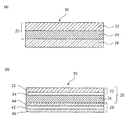
- FIG. 2 (a) is a cross-sectional view showing an example of the configuration of the laminate of the present invention.
- the laminate 30 of the present invention includes an adhesive layer 24, a decorative layer 22 laminated on one surface side of the adhesive layer 24, and an adhesive layer 24. It has the separator layer 26 laminated
- FIG.2 (b) is sectional drawing which shows the preferable structure of the laminated body of this invention.
- the decorative layer 22 is preferably a layer including a surface protective layer 32 and a colored layer 34.
- the separator layer 26 is preferably a layer including a base material layer 42, a release agent layer 44, and an antistatic layer 46.
- the laminate 30 of the present invention may have a layer other than the above-described layers, the configuration in which the decorative layer 22 further has an antistatic layer, and the pressure-sensitive adhesive layer has a colored layer and / or an antistatic layer. The structure which has may be sufficient.
- FIG.2 (b) after the separator layer 26 peels, it becomes the adhesive film 20.
- the laminate of the present invention since the laminate of the present invention has the above-described configuration, it may be in the form of a sheet or may be wound up into a roll. When it is wound up in a roll shape, it is preferable to wind up so that the separator layer is disposed on the core shaft side.
- the laminate of the present invention includes a separator layer.
- the separator layer is preferably made of resin and does not include a paper base material. By using such a separator layer, foreign matters such as paper-derived dust are not caught between the laminate and the molded body, and the biting of foreign matters can be effectively suppressed.
- the surface electrical resistance of the separator layer is preferably 1 ⁇ 10 5 to 1 ⁇ 10 12 ⁇ / ⁇ , and more preferably 1 ⁇ 10 6 to 1 ⁇ 10 12 ⁇ / ⁇ .
- the adhesion of foreign matter can be suppressed by setting the surface electrical resistance of the separator layer within the above range, and particularly during molding under vacuum or reduced pressure conditions (at the time of TOM molding) The biting of foreign matter can be more effectively suppressed.
- the surface electrical resistance of any one surface should just be in the said range for the surface electrical resistance of a separator layer.
- the separator layer has a single layer configuration, and the surface electric resistance of the single layer may be within the above range, but it is preferable that the surface electric resistance has a layer within the above range.
- the separator layer is a base material layer, a release agent layer laminated on one side of the base material layer, and the other surface side of the base material layer, and the release agent layer is laminated. It is preferable to have an antistatic layer laminated on the surface opposite to the surface.
- the surface electrical resistance of the antistatic layer is preferably 1 ⁇ 10 5 to 1 ⁇ 10 12 ⁇ / ⁇ .
- the separator layer preferably contains an antistatic agent
- the pressure-sensitive adhesive film composed of the decorative layer and the pressure-sensitive adhesive layer preferably contains no antistatic agent.
- a separator layer peels from a laminated body and becomes an adhesive film comprised from a decorating layer and an adhesive layer. And this adhesive film is affixed on the molded object which is a to-be-adhered body. That is, when only the separator layer contains the antistatic agent, the decorative molded body does not contain the antistatic agent, and the durability of the whole decorative molded body is further improved.
- the surface electrical resistance of the separator layer can be measured by Hiresta UX MCP-HT800 (manufactured by Mitsubishi Chemical Analytech, measurement method: constant voltage application / leakage current measurement method).
- the separator layer 26 is preferably a layer including a base material layer 42, a release agent layer 44, and an antistatic layer 46. It is preferable to contain an antistatic agent.
- the antistatic agent is preferably at least one selected from ionic antistatic agents, organic antistatic agents, and inorganic antistatic agents, and is selected from organic antistatic agents and inorganic antistatic agents. At least one kind is more preferable, and an inorganic antistatic agent is particularly preferable.
- the organic antistatic agent is more preferably a ⁇ -conjugated conductive polymer antistatic agent.
- the humidity dependence of the antistatic performance can be suppressed. That is, the antistatic performance can be exhibited in any humidity range.
- the inorganic antistatic agent can exhibit excellent antistatic performance even in a low humidity environment.
- an ionic antistatic agent is comparatively cheap, the manufacturing cost of a laminated body can be suppressed.
- any known ionic antistatic agent can be used in the present invention.
- glyceric acid fatty acid ester, polyglycerin fatty acid ester, sorbitan fatty acid ester, polyoxyethylene sorbitan fatty acid ester, polyoxyethylene is used.
- ⁇ -conjugated conductive polymer antistatic agent is preferably used as the organic antistatic agent.
- any known ⁇ -conjugated conductive polymer antistatic agent can be used in the present invention.
- polythiophene, polypyrrole, polyaniline, etc. are used. Particularly preferred is polythiophene.
- any known inorganic antistatic agent can be used in the present invention, and preferable examples include ITO filler, silver nanofiller, and titanium oxide coated with antimony oxide-doped tin oxide. Particularly preferred are silver nanofillers.
- the content of the antistatic agent is preferably 2 to 100% by mass and more preferably 50 to 100% by mass with respect to the total mass of the antistatic layer.
- the coating amount of the antistatic layer after drying is preferably 0.001 to 1 g / m 2 , and particularly preferably 0.01 to 0.2 g / m 2 .
- the base material layer constituting the separator layer is preferably a resin layer, and the resin layer is preferably composed of a thermoplastic resin.
- the base material layer include a polyolefin film, a polyvinyl chloride film, a polyvinyl alcohol film, a polyester film, a polycarbonate film, a polystyrene film, and a polyacrylonitrile film.
- a polyester film is preferably used, and a polyethylene terephthalate (PET) film is particularly preferably used.
- PET polyethylene terephthalate
- the release agent layer contains a release agent.
- a general-purpose addition type or condensation type silicone release agent is used.
- an addition type silicone release agent having high reactivity is preferably used.
- Specific examples of the silicone release agent include BY24-162 and SD-7234 manufactured by Toray Dow Corning Silicone, KS-3600, KS-774, and X62-2600 manufactured by Shin-Etsu Chemical Co., Ltd. Is mentioned.
- the silicone release agent contains a silicone resin that is an organosilicon compound having a SiO 2 unit and a (CH 3 ) 3 SiO 1/2 unit or a CH 2 ⁇ CH (CH 3 ) SiO 1/2 unit. It is preferable to do.
- Specific examples of the silicone resin include BY24-843, SD-7292, SHR-1404, etc. manufactured by Toray Dow Corning Silicone, and KS-3800, X92-183, manufactured by Shin-Etsu Chemical Co., Ltd. .
- Auxiliary additives such as a catalyst and an adhesion improver can be added to the release agent layer.
- Preferred examples of the catalyst include platinum-based and tin-based catalysts. Any adhesion improver can be used as long as adhesion is improved, and a silane coupling agent can be preferably used.
- the coating amount of the release agent layer after drying is preferably 0.01 to 1 g / m 2 and particularly preferably 0.05 to 0.2 g / m 2 .
- the separator layer can be formed by applying a release agent-containing liquid and an antistatic agent-containing liquid to the base material layer and drying.
- a size press coater, gate roll coater, bar coater, roll coater, air knife coater, blade coater, rod blade coater, curtain coater, gravure coater, or the like can be used.
- it is preferable to use a two-head coater that can be applied at one time on the front and back, and a two-head coater that can be coated on the front and back with a gravure head that can control a small amount of coating is particularly preferable.
- a functional layer can be simultaneously formed on both surfaces of a base material layer, and the production efficiency of a separator layer can be improved.
- the step of irradiating with light it is preferable to irradiate with ultraviolet rays having an illuminance of at least 50 mW / cm 2 in a wavelength range of 200 to 400 nm, more preferably 70 to 3000 mW / cm 2. It is particularly preferable to irradiate 100 to 1000 mW / cm 2 of ultraviolet rays. As integrated light quantity, it is particularly preferable preferably from 100 ⁇ 10000mJ / cm 2, a 300 ⁇ 3000mJ / cm 2.
- an irradiator that performs such irradiation it is preferable to use at least one selected from a high-pressure mercury ultraviolet irradiator, a metal halide ultraviolet irradiator, and an electrodeless ultraviolet irradiator.
- the amount of monomer components remaining in the pressure-sensitive adhesive layer can be reduced by setting the irradiation conditions of ultraviolet rays having an illuminance in the wavelength range of 200 to 400 nm of 50 mW / cm 2 or more in the above range. Moreover, it can suppress that a decoration layer yellows with an ultraviolet-ray by making irradiation conditions into the said range.
- irradiation using an ultraviolet ray having an illuminance in the range of 200 to 400 nm and a wavelength of 20 mW / cm 2 or less is performed. It is preferable. More preferably, irradiation is performed using ultraviolet rays having an illuminance in the wavelength range of 200 to 400 nm of 1 to 10 mW / cm 2 , particularly preferably 2 to 5 mW / cm 2 .
- irradiator that performs such irradiation, it is preferable to use at least one selected from a chemical lamp and / or a black light.
- irradiation is preferably carried out for 0.01 to 30 minutes, particularly preferably 0.1 to 20 minutes, so that the integrated light quantity is preferably 10 to 1000 mJ / cm 2 and preferably 40 to 600 mJ / cm 2. it is more preferable to the cm 2, and particularly preferably to 100 ⁇ 400mJ / cm 2.
- the followability of the pressure-sensitive adhesive layer can be enhanced in TOM molding.
- the ratio of the volatile substance contained in the pressure-sensitive adhesive layer can be reduced to a predetermined value or less while increasing the degree of polymerization of the monomer by irradiating ultraviolet rays under the above conditions.
- the laminate of the present invention is preferably used for molding under vacuum conditions or reduced pressure conditions.
- the laminate of the present invention it is possible to prevent foreign matter such as dust from being caught between the pressure-sensitive adhesive layer and the molded body in molding under vacuum conditions or reduced pressure conditions.
- the laminated body of this invention can exhibit the effect by being used for shaping
- molding under vacuum conditions or reduced pressure conditions is so-called TOM molding.
- the TOM molding method includes a step of laminating the pressure-sensitive adhesive film on the molded body under vacuum or reduced pressure conditions, and a step of pressure-bonding the pressure-sensitive adhesive film to the molded body due to a difference in atmospheric pressure.
- molding under a vacuum condition or a reduced pressure condition does not include a method of bringing the pressure-sensitive adhesive film and the molded body into close contact with each other using a vacuum body provided with vacuum holes.
- the molding under a vacuum condition or a reduced pressure condition can be performed by using a “vacuum molding apparatus” described in Japanese Patent No. 3733564.
- the present invention also relates to a method for producing a decorative molded body as described above.
- the method for producing a decorative molded body of the present invention includes a step of laminating an adhesive film on a molded body under vacuum or reduced pressure conditions, and a pressure difference between the pressure sensitive adhesive film and the molded body under pressured air conditions. Crimping.
- the method for producing a decorative molded body of the present invention preferably includes a step of heating the surface of the laminate to 100 to 180 ° C. after the step of pressure-bonding the adhesive film to the molded body. In this case, an infrared heater is preferably used for heating the surface of the laminate.
- the adhesive film used with the manufacturing method of the decorative molded body of this invention is an adhesive film mentioned above, and the volatile substance contained in an adhesive layer is a thing of less than 50 ppm.
- the present invention also relates to a decorative molded body including an adhesive film composed of the decorative layer and the pressure-sensitive adhesive layer of the laminate as described above, and a molded body decorated with the adhesive film.
- the decorative molded body is obtained by attaching an adhesive film to a part or the entire surface of the molded body. That is, in the decorative molded body, the decorative layer is laminated via the pressure-sensitive adhesive layer.
- FIG. 3 is a cross-sectional view illustrating the configuration of the decorative molded body 100.
- FIG. 3 shows a state in which a molded body 50 having a concave portion on the surface is decorated with an adhesive film 20.
- the reverse taper portion and the end winding portion can be covered and molded without providing the molded body 50 with vacuum holes.
- it can decorate regardless of the material of a product. Thereby, it can decorate also about the molded object surface which has a complicated three-dimensional unevenness
- the molded body 50 examples include metal materials such as ED steel plates, Mg alloys, stainless steel (SUS), and aluminum alloys, and resin molded bodies, but resin molded bodies are preferable.
- resin molded bodies are preferable.
- ABS resin acrylonitrile, butadiene and styrene copolymer
- AS resin acrylonitrile and styrene copolymer
- AAS resin acrylonitrile, acrylic and styrene copolymer
- acrylic resin polyethylene terephthalate, Polybutylene terephthalate, nylon, polyacetal, polyphenylene oxide, phenol resin, urea resin, melamine resin, liquid crystal polymer, polytetrafluoroethylene, polyvinylidene fluoride, polysulfone, polyethersulfone, polyacetal, polyetheretherketone, polyphenylenesulfide, polyetherimide , Polyamideimide, polycarbonate, polyethylene, polypropylene, polys
- a polycarbonate-containing resin can be preferably exemplified.
- Polycarbonate-containing resins include resins blended with polycarbonate and polybutylene terephthalate (PC / PBT), resins blended with polycarbonate and ABS resin (PC / ABS), resins blended with polycarbonate and PET (PC) -PET) can be used particularly preferably.
- PC / PBT polybutylene terephthalate
- ABS polycarbonate and ABS
- PC polycarbonate and PET
- PP polypropylene
- an ABS resin a copolymer of acrylonitrile, butadiene, and styrene
- AS resin a copolymer of acrylonitrile and styrene
- AAS resin a copolymer of acrylonitrile, acrylic, and styrene
- an acrylic resin Polyethylene terephthalate, polybutylene terephthalate, nylon, polyacetal, polyphenylene oxide, phenol resin, urea resin, melamine resin, liquid crystal polymer, polytetrafluoroethylene, polyvinylidene fluoride, polysulfone, polyethersulfone, polyacetal, polyetheretherketone, polyphenylene
- Preferred examples include sulfide, polyetherimide, polyamideimide, polycarbonate, polyethylene, polypropylene, polystyrene, and urethane resin. It can be.
- the decorative molded body obtained by the present invention includes, for example, automotive parts (for example, parts such as bodies, bumpers, spoilers, mirrors, wheels, interior materials, etc., and various materials), motorcycle parts, and roads. Used for materials (for example, traffic signs, noise barriers, etc.), tunnel materials (for example, side walls), railway vehicles, furniture, musical instruments, household appliances, building materials, containers, office supplies, sports equipment, toys, etc. it can.
- automotive parts for example, parts such as bodies, bumpers, spoilers, mirrors, wheels, interior materials, etc., and various materials
- materials for example, traffic signs, noise barriers, etc.
- tunnel materials for example, side walls
- railway vehicles for example, furniture, musical instruments, household appliances, building materials, containers, office supplies, sports equipment, toys, etc. it can.
- Example 1 Black ink (DIC, TRC1268) layer (colored layer) on one side of an acrylic film (Mitsubishi Rayon Co., Ltd., Acryprene HBA001P, pencil hardness 2H, thickness 125 ⁇ m) with a gravure printing machine to a thickness of 5 ⁇ m Was provided on the entire surface to obtain a decorative layer 1.
- a release agent comprising 100 parts by mass of thermosetting silicone (manufactured by Toray Dow Corning, LTC300B) and 1 part by mass of catalyst (manufactured by Toray Dow Corning, SRX212) is weight after drying.
- SRX212 titanium dioxide
- treatment was performed at 130 ° C. for 60 seconds with a dryer, and thus a separator layer 1 was obtained.
- Adhesive 1 A reaction vessel in a nitrogen atmosphere was charged with 95 parts by mass of 2-ethylhexyl acrylate and 5 parts by mass of acrylic acid, and an initiator (2,2′-azobis (4-methoxy-2,4-dimethylvaleronitrile)) 0.01 A polymerization reaction was carried out using parts by mass to obtain an adhesive 1 having a polymer concentration of 9% and a weight average molecular weight Mw of 1,500,000.
- the adhesive 1 was applied (wet laminate) between the agent layer side and the ink layer side of the 130 ⁇ m decorative layer 1 so that the thickness of the adhesive layer was 50 ⁇ m.
- irradiation is performed from the separator layer 1 side using a chemical lamp so that the illuminance of ultraviolet light having a wavelength of 365 nm is 4 mW / cm 2 and the integrated light amount is 300 mJ / cm 2, and then ultraviolet light having a wavelength of 365 nm is irradiated with a high-pressure mercury lamp. Irradiation was performed so that the illuminance was 100 mW / cm 2 and the integrated light amount was 2000 mJ / cm 2 , whereby the laminate 1 was obtained. It was 5 ppm when the volatile substance contained in the adhesive layer of the laminated body 1 was measured by the gas chromatography.
- the separator layer 1 was removed from the laminate 1 to obtain an adhesive film 1.
- the adhesive film 1 was set on a TOM molding machine.
- a rainproof cover (manufactured by Panasonic Corporation, product number: WP9171) is placed on a TOM molding machine (manufactured by Fuse Vacuum Co., Ltd., NGF) so that the outer surface (convex surface) side of the cover and the adhesive layer of the adhesive film 1 face each other. Molding machine).
- the decorative molded body 1 was obtained by laminating the adhesive film 1 on the molded body at 130 ° C. using a TOM molding machine. Ten decorative molded bodies 1 were produced in the same manner.
- the shape of the rainproof line cover is shown in FIGS.
- the rainproof cover shown in FIGS. 4 (a) to 4 (c) has a length (longitudinal) direction of 90 mm when viewed from above as shown in FIG.
- the length in the (lateral) direction was 60 mm.
- Example 2 The thickness of the adhesive layer 1 was a 75 [mu] m, the separator layer 1 was changed to the separator layer 2, an ultraviolet irradiation 300 mW / cm 2 illuminance in the wavelength 365nm of ultraviolet rays using a high-pressure mercury lamp, integrated light quantity of only 3000 mJ / cm 2
- the decorative molded body 2 was obtained in the same manner as in Example 1 except that the laminated body 2 was obtained. It was 23 ppm when the volatile substance contained in an adhesive layer was measured.
- a release agent comprising 100 parts by mass of thermosetting silicone (manufactured by Toray Dow Corning, LTC300B) and 1 part by mass of catalyst (manufactured by Toray Dow Corning, SRX212) is dried.
- SRX212 catalyst
- Example 3 The pressure-sensitive adhesive 1 is replaced with the pressure-sensitive adhesive 3, and the pressure-sensitive adhesive layer 3 is formed to a thickness of 25 ⁇ m.
- the illuminance of ultraviolet light with a wavelength of 365 nm is 4 mW / cm 2 and the integrated light quantity is 100 mJ / cm. irradiated at 2, then a high-pressure mercury lamp at a wavelength 365nm of illumination 100 mW / cm 2 of ultraviolet, integrated light quantity is irradiated so that the 2000 mJ / cm 2, except that to obtain a laminate 3
- the decorative molded body 3 was obtained in the same manner as in Example 2. It was 3 ppm when the volatile substance contained in the adhesive layer of the laminated body 3 was measured.
- ⁇ Adhesive 3> In a reaction vessel in a nitrogen atmosphere, 90 parts by mass of 2-ethylhexyl acrylate, 5 parts by mass of acrylic acid, and 5 parts by mass of isobornyl acrylate were charged with an initiator (2,2′-azobis (4-methoxy-2,4-dimethyl). Valeronitrile)) A polymerization reaction was carried out using 0.01 part by mass to obtain a pressure-sensitive adhesive 3 having a polymer concentration of 8% and a weight average molecular weight Mw of 2 million.
- Example 4 The pressure-sensitive adhesive 1 is replaced with a pressure-sensitive adhesive 4 to form a pressure-sensitive adhesive layer 4, the separator layer 3 is used in place of the decorative layer 1, and the illuminance of ultraviolet light having a wavelength of 365 nm is 100 mW / in a metal halide lamp instead of a high-pressure mercury lamp. cm 2, integrated light quantity irradiated so that the 2000 mJ / cm 2, the separator 1 / create what the configuration of the pressure-sensitive adhesive layer 4 / the separator 3, peeled the next separator 1, the pressure-sensitive adhesive layer 4 which bared A decorative molded body 4 was obtained in the same manner as in Example 1 except that the laminate 4 was obtained by laminating with the decorative layer 1 using a roll laminator. It was 14 ppm when the volatile substance contained in the adhesive layer of the laminated body 4 was measured.
- a rosin-based tackifier manufactured by Arakawa Chemical Co., KE311
- ⁇ Separator layer 3 Silver nanowire (Cold stones, CST-NW-S40) and polyester binder (Takamatsu Yushi, Pesresin A-645GH) are blended so that the weight after drying is 20:80, and the thickness is 50 ⁇ m.
- PET Toray Co., Ltd., Lumirror T60.
- the coating amount was set to 0.01 g / m 2 after drying, and coating was performed in a clean room (class 1000). Thereafter, treatment was performed at 130 ° C. for 30 seconds in a dryer to form an antistatic layer D.
- a release agent comprising 100 parts by mass of thermosetting silicone (manufactured by Toray Dow Corning, LTC300B) and 1 part by mass of catalyst (manufactured by Toray Dow Corning, SRX212) is dried.
- a clean room class 1000
- treatment was performed at 130 ° C. for 60 seconds with a dryer, and a separator layer 3 was obtained.
- Example 5 A laminate 5 was prepared in the same manner as in Example 4 except that the pressure-sensitive adhesive 1 was replaced with the pressure-sensitive adhesive 5 and the thickness of the pressure-sensitive adhesive layer 5 was set to 25 ⁇ m to obtain a decorative molded body 5. It was 4 ppm when the volatile substance contained in the adhesive layer of the laminated body 5 was measured.
- ⁇ Adhesive 5> In a reaction vessel in a nitrogen atmosphere, 90 parts by mass of 2-ethylhexyl acrylate and 10 parts by mass of acrylic acid were charged, and initiator (2,2′-azobis (4-methoxy-2,4-dimethylvaleronitrile)) 0.01 A polymerization reaction was carried out using parts by mass to obtain a solution 5 having a polymer concentration of 11% and a weight average molecular weight Mw of 1,500,000.
- Example 6 A laminate 6 was prepared in the same manner as in Example 2 except that the thickness of the pressure-sensitive adhesive layer was 200 ⁇ m and the separator layer 2 was replaced with the separator layer 4 to obtain a decorative molded body 6. It was 30 ppm when the volatile substance contained in the adhesive layer of the laminated body 6 was measured.
- ⁇ Separator layer 4> On one side of 38 ⁇ m thick PET (Toray Industries, Lumirror T60), 100 parts by mass of thermosetting silicone (Toray Dow Corning, LTC300B), 1 part by mass of catalyst (Toray Dow Corning, SRX212) The release agent consisting of was applied at a weight after drying of 0.1 g / m 2 to form a release agent layer. Thereafter, treatment was performed at 130 ° C. for 60 seconds with a dryer, and a separator layer 4 was obtained.
- PET Toray Industries, Lumirror T60
- thermosetting silicone Toray Dow Corning, LTC300B
- catalyst Toray Dow Corning, SRX212
- ⁇ Laminated body 11> The pressure-sensitive adhesive 11 is applied on the release agent layer of the separator layer 4 so that the thickness after drying is 25 ⁇ m, dried at 90 ° C. for 10 minutes, and then the decorative layer 1 is pasted with a roll laminator. As a result, a laminate 11 was obtained.
- the obtained polymer A had a weight average molecular weight Mw of 800,000.
- the pressure-sensitive adhesive 11 was obtained by blending such that the ratio was 98: 10: 2.
- a laminate 12 was obtained in the same manner as in Comparative Example 1, except that the pressure-sensitive adhesive 12 was applied on the release agent layer of the separator layer 2 so that the thickness after drying was 75 ⁇ m.
- the obtained polymer B, a cross-linking agent (manufactured by Mitsubishi Gas Chemical Co., Ltd., Tetrad X), and bistrifluoromethanesulfonimide were blended in a dry weight ratio of 96: 2: 2 to obtain an adhesive 12. It was.
- a laminate 13 was obtained in the same manner as in Example 1 except that the illuminance of ultraviolet light having a wavelength of 365 nm was 100 mW / cm 2 and the integrated light amount was 50 mJ / cm 2 with a high-pressure mercury lamp. It was 610 ppm when the volatile substance contained in the adhesive layer of the laminated body 13 was measured.
- ⁇ Laminated body 14 Structure of separator 1 / adhesive layer 4 / separator 3 in the same manner as in Example 4 except that irradiation is performed with a metal halide lamp so that the illuminance of ultraviolet light having a wavelength of 365 nm is 100 mW / cm 2 and the integrated light quantity is 50 mJ / cm 2. Then, the separator 1 was peeled off, and the exposed adhesive layer 4 was bonded to the decorative layer 1 using a roll bonding machine to obtain a laminate 14. It was 310 ppm when the volatile substance contained in the adhesive layer of the laminated body 14 was measured.
- the upper surface of the decorative molded body obtained in each example and comparative example region corresponding to the upper surface of FIG. 4A is observed with a laser microscope (VK-X100, manufactured by Keyence), and the height is 3 ⁇ m or more. The number was counted as a defect.
- the number of defects is an average value of the number of defects in the same region of 10 decorative molded bodies produced in the same manner in each example and each comparative example.
- a test piece of 25 ⁇ 50 mm is attached to an ABS plate, subjected to pressure bonding (2 kg roller, 1 reciprocation), and heat treatment (130 ° C., 1 minute), left for 24 hours, and then peeled off using a tensile tester.
- a peeling speed of 300 mm / min a peeling angle of 180 degrees, a measurement temperature of 23 ° C., and a measurement humidity of 50%, the force required for peeling was measured.
- the decorative molded body was allowed to stand in an environment of 80 ° C. for 500 hours, and after that, at room temperature, the surface of the film was cut at 2 mm intervals in the length and width of 11 to make 100 grids.
- the cellophane tape was brought into close contact with the surface and peeled off at once, the number of cells remaining without peeling was displayed.
- the TOM moldability was good.
- the pressure-sensitive adhesive film obtained in the comparative example foaming occurred from the pressure-sensitive adhesive layer.
- the laminated body obtained by the Example has few defects, and exhibits favorable adhesive force with respect to a molded object. Furthermore, it turns out that the decoration molded object obtained in the Example is excellent in durability.
Landscapes
- Chemical & Material Sciences (AREA)
- Organic Chemistry (AREA)
- Physics & Mathematics (AREA)
- Fluid Mechanics (AREA)
- Engineering & Computer Science (AREA)
- Mechanical Engineering (AREA)
- Laminated Bodies (AREA)
- Adhesive Tapes (AREA)
- Adhesives Or Adhesive Processes (AREA)
- Blow-Moulding Or Thermoforming Of Plastics Or The Like (AREA)
Abstract
Description
本願は、2015年6月15日に出願された日本国特願2015−120042号に基づく優先権を主張し、その内容をここに援用する。
粘着剤層を構成する粘着剤には、一般的に溶剤系粘着剤が用いられているが、紫外線硬化型接着剤を用いることも検討されている。例えば、特許文献2には、加飾層と、電離放射線硬化型接着剤層とを有する加飾シートが開示されている。ここでは、電離放射線硬化型接着剤層は一定時間仮接着をすることが可能な性質を有し、接着剤を構成するモノマー成分の重合反応は、経時的に進行する。
また、特許文献2では、粘着剤層に紫外線硬化型接着剤を用いることが検討されているが、特許文献2の加飾フィルムをTOM成形に用いた場合、仮接着をした後に発泡しやすく、加飾成形体の歩留まり等を悪化させることが本発明者らの検討により明らかとなった。
[1]粘着剤層と、粘着剤層の一方の面側に積層された加飾層とを有し、粘着剤層に含まれる揮発性物質が50ppm未満であることを特徴とする粘着フィルム。
[2]粘着剤層を構成する粘着剤は、紫外線硬化型粘着剤である[1]に記載の粘着フィルム。
[3]揮発性物質が、粘着剤層を構成する粘着剤の構成成分であるモノマー、及び粘着剤層を構成する粘着剤の構成成分であるオリゴマーから選択される少なくとも1種である[1]又は[2]に記載の粘着フィルム。
[4]粘着剤層を構成する粘着剤は、(メタ)アクリル酸エステルモノマー単位を含む[1]~[3]のいずれかに記載の粘着フィルム。
[5]粘着剤層の厚みが20μm以上である[1]~[4]のいずれかに記載の粘着フィルム。
[6]加飾層の厚みが75μm以上である[1]~[5]のいずれかに記載の粘着フィルム。
[7]真空条件下又は減圧条件下での成形用に用いられる[1]~[6]のいずれかに記載の粘着フィルム。
[8]粘着剤層と、粘着剤層の一方の面側に積層された加飾層と、粘着剤層の他方の面側であって、加飾層が積層された面とは反対の面側に積層されたセパレーター層とを有する積層体であって、粘着剤層に含まれる揮発性物質が50ppm未満であることを特徴とする積層体。
[9]粘着剤層、加飾層、及びセパレーター層の少なくともいずれかは、表面電気抵抗が1×10⁵~1×10¹²Ω/□である層を有する[8]に記載の積層体。
[10]セパレーター層は、表面電気抵抗が1×10⁵~1×10¹²Ω/□である層を有する[8]又は[9]に記載の積層体。
[11][1]~[7]のいずれかに記載の粘着フィルムと、粘着フィルムで加飾された成形体とを含む加飾成形体。
[12]真空条件下又は減圧条件下において、粘着フィルムを成形体に積層する工程と、気圧差により、粘着フィルムを成形体に圧着する工程とを含み、粘着フィルムは、粘着剤層と、粘着剤層の一方の面側に積層された加飾層とを有し、粘着剤層に含まれる揮発性物質が50ppm未満である加飾成形体の製造方法。
本発明の粘着フィルムは、粘着剤層と、粘着剤層の一方の面側に積層された加飾層とを有する。粘着剤層に含まれる揮発性物質は50ppm未満である。粘着剤層に含まれる揮発性物質は30ppm未満であることが好ましく、15ppm以下であることがより好ましく、5ppm以下であることが特に好ましい。ここで、揮発性物質とは、150℃の真空条件下において、揮散する物質をいう。また、本発明の粘着フィルムとは、被着対象(成形体)に貼り合わせるTOM成形前のフィルムのことをいい、本発明では、貼り合わせ前の粘着フィルムにおいて揮発性物質の含有率が上記範囲である点に特徴がある。
粘着剤層を構成する粘着剤は、紫外線硬化型粘着剤(UV硬化型粘着剤)であることが好ましく、アクリル系紫外線硬化型粘着剤であることがより好ましい。紫外線硬化型粘着剤としては、例えば、アクリル系モノマー及び/又はアクリル系オリゴマーと光重合開始剤とを含有する無溶剤型粘着剤が挙げられる。
(メタ)アクリル酸エステルモノマーとしては、例えば、(メタ)アクリル酸メチル、(メタ)アクリル酸エチル、(メタ)アクリル酸プロピル、(メタ)アクリル酸イソプロピル、(メタ)アクリル酸n−ブチル、(メタ)アクリル酸イソブチル、(メタ)アクリル酸t−ブチル、(メタ)アクリル酸n−ペンチル、(メタ)アクリル酸n−ヘキシル、(メタ)アクリル酸2−エチルヘキシル、(メタ)アクリル酸n−オクチル、(メタ)アクリル酸イソオクチル、(メタ)アクリル酸n−ノニル、(メタ)アクリル酸イソノニル、(メタ)アクリル酸n−デシル、(メタ)アクリル酸イソデシル、(メタ)アクリル酸n−ウンデシル、(メタ)アクリル酸ウラリル、(メタ)アクリル酸n−ドデシル、(メタ)アクリル酸ステアリル、(メタ)アクリル酸イソステアリル、(メタ)アクリル酸イソボニル、(メタ)アクリル酸メトキシエチル、(メタ)アクリル酸エトキシエチル、(メタ)アクリル酸シクロヘキシル、(メタ)アクリル酸ベンジル等が挙げられる。これらは1種を単独で使用してもよいし、2種以上を併用してもよい。
中でも、(メタ)アクリル酸メチル、(メタ)アクリル酸n−ブチル、(メタ)アクリル酸イソブチル、(メタ)アクリル酸2−エチルヘキシルから選ばれる少なくとも1種を用いることが好ましい。
アセトフェノン系開始剤として、具体的には、ジエトキシアセトフェノン、ベンジルジメチルケタール等が挙げられる。
ベンゾインエーテル系開始剤として、具体的には、ベンゾイン、ベンゾインメチルエーテル等が挙げられる。
ベンゾフェノン系開始剤として、具体的には、ベンゾフェノン、o−ベンゾイル安息香酸メチル等が挙げられる。
ヒドロキシアルキルフェノン系開始剤として、具体的には、1−ヒドロキシ−シクロヘキシル−フェニル−ケトン、2−ヒドロキシ−2−メチル−1−フェニル−プロパン−1−オン等が挙げられる。
チオキサントン系開始剤として、具体的には、2−イソプロピルチオキサントン、2,4−ジメチルチオキサントン等が挙げられる。
アミン系開始剤として、具体的には、トリエタノールアミン、4−ジメチル安息香酸エチル等が挙げられる。
アシルフォスフィンオキサイド系開始剤として、具体的には、2,4,6−トリメチルベンゾイル−ジフェニル−フォスフィンオキサイド、ビス(2,4,6−トリメチルベンゾイル)−フェニルフォスフィンオキサイド等が挙げられる。
アクリル系ポリマーの分子量の分布を広くすることにより、真空条件下又は減圧条件下での成形(TOM成形)時に、成形体への追従性を高めることができ、複雑な形状の成形体も加飾することができる。
本発明の積層体は、加飾層を含む。加飾層は、単層構成であってもよいが、紫外線吸収剤を含有する表面保護層と、有色層とを有する層であることが好ましい。なお、有色層は、顔料、染料、金属、金属酸化物等を含有することが好ましい。有色層は、顔料、染料、金属、金属酸化物を含有する樹脂層であってもよく、顔料、染料、金属、金属酸化物からなる蒸着、スパッタ層でもよく、また顔料、染料、金属、金属酸化物を含むインキ層を、加飾層に印刷で施したものであってもよい。この場合は、その印刷部のことを有色層(有色部)と呼んでもよい。この場合の、印刷方法としては特に制限されず、例えば、凸版印刷、オフセット印刷、フレキソ印刷、グラビア印刷、インクジェット印刷などが挙げられる。これらの印刷に用いる印刷インキとしては、酸化重合型の油性インキ、大豆油インキ、ベジタブルオイルインキ、紫外線硬化型のUVインキ、LED−UVインキ、グラビアインキ、フレキソインキ、スクリーンインキ等を挙げることができ、特にグラビアインキ、スクリーンインキ、インクジェットインキが好ましい。印刷インキには、必要に応じて、顔料分散剤、消泡剤、紫外線吸収剤、酸化防止剤、帯電防止剤、耐磨耗防止剤、ブロッキング防止剤などの添加剤が添加されていてもよい。
本発明は、粘着剤層と、粘着剤層の一方の面側に積層された加飾層と、粘着剤層の他方の面側であって、加飾層が積層された面とは反対の面側に積層されたセパレーター層とを有する積層体に関するものでもある。ここで、粘着剤層に含まれる揮発性物質は50ppm未満である。
なお、図2(b)に示されたような積層体30においてもセパレーター層26が剥離された後は、粘着フィルム20となる。
本発明の積層体は、セパレーター層を含む。セパレーター層は、樹脂製であり、紙基材を含まない層であることが好ましい。このようなセパレーター層を用いることにより、紙由来のゴミ等の異物が、積層体と成形体との間に挟まることがなくなり、異物の噛み込みを効果的に抑制することができる。
剥離剤層の乾燥後の塗布量は、0.01~1g/m2であることが好ましく、0.05~0.2g/m2であることが特に好ましい。
本発明の積層体を製造する工程においては、上述した構成となるように、加飾層と、粘着剤層と、セパレーター層とを積層した後に、光線(紫外線又は電子線)を照射することが好ましい。また、セパレーター層と、粘着層と、セパレーター層とを積層した後に、光線(紫外線又は電子線)を照射し、これと加飾層とを貼り合せることで上述した構成にすることも可能である。加飾層を含んだ構成にて光線を照射する場合は、光線(紫外線又は電子線)を、セパレーター層側から照射することが好ましい。
本発明では、上記のような条件で紫外線を照射することにより、モノマーの重合度と高めつつ、粘着剤層に含まれる揮発性物質の割合を所定値以下とすることができる。
本発明の積層体は、真空条件下又は減圧条件下での成形用に用いられることが好ましい。本発明の積層体を用いることにより、真空条件下又は減圧条件下での成形において、粘着剤層と成形体との間に、ゴミ等の異物を噛み込むことを抑制することができる。このように、本発明の積層体は、真空条件下又は減圧条件下での成形に用いられることにより、その効果を発揮することができる。
なお、本発明の加飾成形体の製造方法で用いられる粘着フィルムは、上述した粘着フィルムであり、粘着剤層に含まれる揮発性物質が50ppm未満のものである。
本発明は、上述したような積層体の加飾層及び粘着剤層から構成される粘着フィルムと、粘着フィルムで加飾された成形体とを含む加飾成形体に関するものでもある。加飾成形体は、成形体の表面の一部又は全面に粘着フィルムを貼着させたものである。すなわち、加飾成形体においては、加飾層が粘着剤層を介して積層されている。
具体的には、ABS樹脂(アクリロニトリル、ブタジエン、及びスチレンの共重合体)、AS樹脂(アクリロニトリル及びスチレンの共重合体)、AAS樹脂(アクリロニトニル、アクリル、及びスチレンの共重合体)、アクリル樹脂、ポリエチレンテレフタレート、ポリブチレンテレフタレート、ナイロン、ポリアセタール、ポリフェニレンオキシド、フェノール樹脂、ユリア樹脂、メラミン樹脂、液晶ポリマー、ポリテトラフロロエチレン、ポリフッ化ビニリデン、ポリサルフォン、ポリエーテルサルフォン、ポリアセタール、ポリエーテルエーテルケトン、ポリフェニレンサルファイド、ポリエーテイミド、ポリアミドイミド、ポリカーボネート、ポリエチレン、ポリプロピレン、ポリスチレン、ウレタン樹脂等を好ましく挙げることができる。
<加飾層1>
アクリルフィルム(三菱レイヨン社製、アクリプレンHBA001P、鉛筆硬度は2H、厚さ125μm)の片面上に、グラビア印刷機にて厚みが5μmとなるように墨インキ(DIC製、TRC1268)層(有色層)を全面に設け、加飾層1を得た。
厚さ38μmのPET(東レ社製、ルミラーT60)の片面上に、π共役系有機導電材料:ポリ(3,4−エチレンジオキシチオフェン)を含むデナトロンP−502S(ナガセケムテックス製)を、乾燥後の塗工量が0.07g/m2になるように塗布し、乾燥機にて130℃、30秒間処理を行った。このようにして、帯電防止層を形成した。
次に、反対面上に、熱硬化型シリコーン(東レ・ダウコーニング社製、LTC300B)100質量部、触媒(東レ・ダウコーニング社製、SRX212)1質量部からなる剥離剤を、乾燥後の重量で0.1g/m2になるように塗布し、剥離剤層を形成した。その後、乾燥機にて130℃、60秒間処理を行い、セパレーター層1を得た。
窒素雰囲気の反応容器中に、2−エチルヘキシルアクリレート 95質量部、アクリル酸 5質量部を仕込み、開始剤(2,2’−アゾビス(4−メトキシ−2,4−ジメチルバレロニトリル))0.01質量部を用いて重合反応を行い、ポリマー濃度9%、重量平均分子量Mw150万の粘着剤1を得た。
粘着剤1 100質量部に、ヘキサンジオールジアクリレート0.1質量部、ベンジルシメチルケタール1質量部を添加し、窒素ガスをパージして溶存する酸素を完全に除去して、セパレーター層1の剥離剤層側と、130μmの加飾層1のインキ層側との間に、粘着剤1を粘着剤層の厚さが50μmとなるよう塗布(ウエットラミネート)した。その後、セパレーター層1側からケミカルランプを用いて、波長365nmの紫外線の照度4mW/cm2、積算光量が300mJ/cm2となるように照射し、次に高圧水銀ランプにて波長365nmの紫外線の照度が100mW/cm2、積算光量が2000mJ/cm2となるように照射して、積層体1を得た。積層体1の粘着剤層に含まれる揮発性物質をガスクロマトグラフィーにより測定したところ、5ppmであった。
積層体1からセパレーター層1を取り外し、粘着フィルム1とした。その粘着フィルム1をTOM成形機にセットした。防雨入線カバー(パナソニック株式会社製、品番:WP9171)を、該カバーの外面(凸面)側と上記粘着フィルム1の粘着剤層とが向き合うように、TOM成形機(布施真空株式会社製、NGF成形機)にセットした。TOM成形機を用いて130℃で粘着フィルム1を上記成形体に積層させることによって、加飾成形体1を得た。同じようにして加飾成形体1を10個作製した。
なお、上記防雨入線カバーの形状を図4(a)~(c)に示す。図4(a)~(c)に示されている防雨入線カバーは、図4(a)のように上方から観察したときに、長さ(縦)方向の長さが90mmであり、幅(横)方向の長さが60mmであった。
粘着剤層1の厚さを75μmとし、セパレーター層1をセパレーター層2に変更し、紫外線照射を高圧水銀ランプにて波長365nmの紫外線の照度が300mW/cm2、積算光量が3000mJ/cm2のみとして積層体2を得た以外は、実施例1と同様にして加飾成形体2を得た。粘着剤層に含まれる揮発性物質を測定したところ、23ppmであった。
厚さ50μmのPET(東レ社製、ルミラーT60)の片面上に、グリセリンモノステアレートを、乾燥後の塗工量が0.15g/m2になるように塗布し、乾燥機にて130℃、30秒間処理を行った。このようにして、帯電防止層を形成した。
次に、反対面上に、熱硬化型シリコーン(東レ・ダウコーニング社製、LTC300B)100質量部と、触媒(東レ・ダウコーニング社製、SRX212)1質量部とからなる剥離剤を、乾燥後の重量で0.1g/m2になるように塗布し、剥離剤層を形成した。その後、乾燥機にて130℃、60秒間処理を行い、セパレーター層2を得た。
粘着剤1を粘着剤3に代えて粘着剤層3を厚さ25μmとして形成し、セパレーター層2側からケミカルランプを用いて、波長365nmの紫外線の照度4mW/cm2、積算光量が100mJ/cm2となるように照射し、次に高圧水銀ランプにて波長365nmの紫外線の照度が100mW/cm2、積算光量が2000mJ/cm2となるように照射して、積層体3を得た以外は、実施例2と同様にして加飾成形体3を得た。積層体3の粘着剤層に含まれる揮発性物質を測定したところ、3ppmであった。
窒素雰囲気の反応容器中に、2−エチルヘキシルアクリレート 90質量部、アクリル酸 5質量部、アクリル酸イソボルニル 5質量部を仕込み、開始剤(2,2’−アゾビス(4−メトキシ−2,4−ジメチルバレロニトリル))0.01質量部を用いて重合反応を行い、ポリマー濃度8%、重量平均分子量Mw200万の粘着剤3を得た。
粘着剤1を粘着剤4に代えて粘着剤層4を形成し、加飾層1の代わりにセパレーター層3を用い、また高圧水銀ランプに代えメタルハライドランプにて波長365nmの紫外線の照度が100mW/cm2、積算光量が2000mJ/cm2となるように照射し、セパレーター1/粘着剤層4/セパレーター3の構成のものを作成し、次のセパレーター1を剥がし、むき出しになった粘着剤層4にロール貼合機を用いて加飾層1と貼合し、積層体4を得た以外は実施例1と同様にし、加飾成形体4を得た。積層体4の粘着剤層に含まれる揮発性物質を測定したところ、14ppmであった。
窒素雰囲気の反応容器中に、ブチルアクリレート 95質量部、2−ヒドロキシメチルアクリレート 5質量部を仕込み、開始剤(2,2’−アゾビス(4−メトキシ−2,4−ジメチルバレロニトリル))0.01質量部を用いて重合反応を行い、ポリマー濃度11%、重量平均分子量Mw100万の溶液4を得た。この溶液4にロジン系粘着付与剤(荒川化学製、KE311)15質量部を添加し、攪拌して粘着剤4を得た。
銀ナノワイヤー(Cold stones製、CST−NW−S40)と、ポリエステル系バインダー(高松油脂製、ペスレジンA−645GH)とを、乾燥後の重量で20:80になるように配合し、厚さ50μmのPET(東レ社製、ルミラーT60)の片面上に塗布した。塗布量は乾燥後の塗工量が0.01g/m2になるようにし、塗布はクリーンルーム(クラス1000)の中で行った。その後、乾燥機にて130℃、30秒間処理を行い、帯電防止層Dを形成した。
次に、反対面上に、熱硬化型シリコーン(東レ・ダウコーニング社製、LTC300B)100質量部と、触媒(東レ・ダウコーニング社製、SRX212)1質量部とからなる剥離剤を、乾燥後の重量で0.1g/m2になるようにクリーンルーム(クラス1000)の中で塗布し、剥離剤層を形成した。その後、乾燥機にて130℃、60秒間処理を行い、セパレーター層3を得た。
粘着剤1を粘着剤5に代えて粘着剤層5の厚さを25μmとした以外は、実施例4と同様にして積層体5を作成し加飾成形体5を得た。
積層体5の粘着剤層に含まれる揮発性物質を測定したところ、4ppmであった。
窒素雰囲気の反応容器中に、2−エチルヘキシルアクリレート 90質量部、アクリル酸 10質量部を仕込み、開始剤(2,2’−アゾビス(4−メトキシ−2,4−ジメチルバレロニトリル))0.01質量部を用いて重合反応を行い、ポリマー濃度11%、重量平均分子量Mw150万の溶液5を得た。この溶液5に、テルペン系粘着付与剤(ヤスハラケミカル製、TH130)10質量部と、脂肪族炭化水素系粘着付与剤(荒川化学製、アルコンM100)とを添加し攪拌して、粘着剤5を得た。
粘着剤層の厚さを200μmとし、セパレーター層2をセパレーター層4に代えた以外は、実施例2と同様にして積層体6を作成し加飾成形体6を得た。積層体6の粘着剤層に含まれる揮発性物質を測定したところ、30ppmであった。
厚さ38μmのPET(東レ社製、ルミラーT60)の片面上に、熱硬化型シリコーン(東レ・ダウコーニング社製、LTC300B)100質量部、触媒(東レ・ダウコーニング社製、SRX212)1質量部からなる剥離剤を、乾燥後の重量で0.1g/m2になるように塗布し、剥離剤層を形成した。その後、乾燥機にて130℃、60秒間処理を行い、セパレーター層4を得た。
積層体11からセパレーター層4を剥離した粘着フィルム11を用いて加飾成形体11を得ようとしたが、TOM成形機を用いて130℃で加工する際に粘着剤層が発泡を起し、良好な加飾成形体を得ることができなかった。積層体11の粘着剤層に含まれる揮発性物質を測定したところ、80ppmであった。
セパレーター層4の剥離剤層上に、乾燥後の厚さが25μmとなるように粘着剤11を塗布し、90℃で10分間にわたって乾燥した後、加飾層1をロール貼合機にて貼合して、積層体11を得た。
ブチルアクリレート65質量部、メチルアクリレート30質量部、アクリル酸5質量部を、窒素雰囲気の反応容器(温度コントローラー、攪拌機、還流器付)に投入し、酢酸エチルを200質量部と、アソビスイソブチロニトリル0.1質量部とを加えて重合反応を行い、ポリマーAを得た。得られたポリマーAの重量平均分子量Mwは80万であった。得られたポリマーAと、ポリαメチルスチレン(分子量Mw=850,000、Tg=105℃、和光純薬製)と、架橋剤(三菱瓦斯化学社製、テトラドX)とを、乾燥重量比で98:10:2となるように配合して粘着剤11を得た。
積層体12からセパレーター層2を剥離した粘着フィルム12を用いて加飾成形体12を得ようとしたが、TOM成形機を用いて130℃で加工する際に粘着剤層が発泡を起し、良好な加飾成形体を得ることができなかった。積層体12の粘着剤層に含まれる揮発性物質を測定したところ、140ppmであった。
セパレーター層2の剥離剤層上に、乾燥後の厚さが75μmとなるように粘着剤12を塗布する以外、比較例1と同様にして積層体12を得た。
ブチルアクリレート65質量部、メチルアクリレート30質量部、2−ヒドロキシエチルアクリレート5質量部を、窒素雰囲気の反応容器(温度コントローラー、攪拌機、還流器付)に投入し、酢酸エチル200質量部と、アソビスイソブチロニトリル0.1質量部とを加えて重合反応を行い、ポリマーBを得た。得られたポリマーBの重量平均分子量Mwは80万であった。
得られたポリマーBと、架橋剤(三菱瓦斯化学社製、テトラドX)と、ビストリフルオロメタンスルホンイミドとを、乾燥重量比で96:2:2となるように配合して粘着剤12を得た。
積層体13からセパレーター層1を剥離した粘着フィルム13を用いて加飾成形体13を得ようとしたが、TOM成形機を用いて130℃で加工する際に粘着剤層が発泡を起し、良好な加飾成形体を得ることができなかった。
高圧水銀ランプにて波長365nmの紫外線の照度が100mW/cm2、積算光量が50mJ/cm2とする以外、実施例1と同様にして積層体13を得た。積層体13の粘着剤層に含まれる揮発性物質を測定したところ、610ppmであった。
積層体14からセパレーター層1を剥離した粘着フィルム14を用いて加飾成形体14を得ようとしたが、TOM成形機を用いて130℃で加工する際に粘着剤層が発泡を起し、良好な加飾成形体を得ることができなかった。
メタルハライドランプにて波長365nmの紫外線の照度が100mW/cm2、積算光量が50mJ/cm2となるように照射する以外、実施例4と同様にしてセパレーター1/粘着剤層4/セパレーター3の構成のものを作成し、次にセパレーター1を剥がし、むき出しになった粘着剤層4にロール貼合機を用いて加飾層1と貼合し、積層体14を得た。積層体14の粘着剤層に含まれる揮発性物質を測定したところ、310ppmであった。
(表面電気抵抗値の測定)
表面電気抵抗は、積層体を23℃、50%Hの環境下に1日調湿放置した後、ハイレスターUX MCP−HT800(三菱化学アナリテック社製)にて測定した。
実施例1~6及び比較例1~4の粘着フィルムを成形した際、発泡がなかったものを、成形性が良好(○)と評価した。フィルム成形時に、発泡が見受けられたものを、成形性が悪い(×)と評価した。結果を表1に示す。
23℃、相対湿度50%の環境下でエージングを行った積層体(粘着フィルム)を用いた加飾成形体の表面を観察し、表面の凸状に膨れた欠陥数を計測した。各実施例及び比較例で得た加飾成形体の上面(図4(a)の上面に対応する領域)をレーザー顕微鏡(VK−X100、キーエンス製)で観察し、高さが3μm以上のものを欠陥として数を計測した。なお、欠陥数は、各実施例及び各比較例においてそれぞれ同様に作製した10個の加飾成形体の同領域の欠陥数の平均値である。
15℃、相対湿度30%の環境下でエージングを行った積層体(粘着フィルム)を用いた加飾成形体の表面を上記と同様の方法で観察し、欠陥数を計測し、平均値を求めた。
25×50mmの試験片をABS板に貼り付け、圧着貼合(2kgローラー、1往復)、及び熱処理(130℃、1分)を行い、24時間放置した後、引っ張り試験機を用いて、剥離速度300mm/minの剥離速度、剥離角度180度、測定温度23℃、測定湿度50%の条件で試験片を剥がしたときに、剥がすのに要する力を測定した。
80℃の環境下で加飾成形体を500時間放置し、放置後に室温下にてフィルムの表面に2mm間隔で縦、横11本の切れ目を入れて100個の碁盤目を作った。セロハンテープをその表面に密着させた後一気に剥がした時に剥離せず残存したマス目の個数を表示した。

また、実施例で得られた積層体は、欠陥数が少なく、成形体に対して良好な粘着力を発揮する。さらに、実施例で得られた加飾成形体は、耐久性が優れていることがわかる。
Claims (12)
- 粘着剤層と、前記粘着剤層の一方の面側に積層された加飾層とを有し、
前記粘着剤層に含まれる揮発性物質が50ppm未満であることを特徴とする粘着フィルム。 - 前記粘着剤層を構成する粘着剤は、紫外線硬化型粘着剤である請求項1に記載の粘着フィルム。
- 前記揮発性物質が、溶剤、前記粘着剤層を構成する粘着剤の構成成分であるモノマー、及び前記粘着剤層を構成する粘着剤の構成成分であるオリゴマーから選択される少なくとも1種である請求項1又は2に記載の粘着フィルム。
- 前記粘着剤層を構成する粘着剤は、(メタ)アクリル酸エステルモノマー単位を含む請求項1~3のいずれか1項に記載の粘着フィルム。
- 前記粘着剤層の厚みが20μm以上である請求項1~4のいずれか1項に記載の粘着フィルム。
- 前記加飾層の厚みが75μm以上である請求項1~5のいずれか1項に記載の粘着フィルム。
- 真空条件下又は減圧条件下での成形用に用いられる請求項1~6のいずれか1項に記載の粘着フィルム。
- 粘着剤層と、前記粘着剤層の一方の面側に積層された加飾層と、前記粘着剤層の他方の面側であって、前記加飾層が積層された面とは反対の面側に積層されたセパレーター層とを有する積層体であって、
前記粘着剤層に含まれる揮発性物質が50ppm未満であることを特徴とする積層体。 - 前記粘着剤層、前記加飾層、及び前記セパレーター層の少なくともいずれかは、表面電気抵抗が1×10⁵~1×10¹²Ω/□である層を有する請求項8に記載の積層体。
- 前記セパレーター層は、表面電気抵抗が1×10⁵~1×10¹²Ω/□である層を有する請求項8又は9に記載の積層体。
- 請求項1~7のいずれか1項に記載の粘着フィルムと、前記粘着フィルムで加飾された成形体とを含む加飾成形体。
- 真空条件下又は減圧条件下において、粘着フィルムを成形体に積層する工程と、
気圧差により、前記粘着フィルムを前記成形体に圧着する工程とを含み、
前記粘着フィルムは、粘着剤層と、前記粘着剤層の一方の面側に積層された加飾層とを有し、前記粘着剤層に含まれる揮発性物質が50ppm未満である加飾成形体の製造方法。
Priority Applications (3)
| Application Number | Priority Date | Filing Date | Title |
|---|---|---|---|
| CN201680033342.0A CN107636099B (zh) | 2015-06-15 | 2016-06-13 | 粘着膜、层叠体及装饰成型体 |
| KR1020177035124A KR102255602B1 (ko) | 2015-06-15 | 2016-06-13 | 점착 필름, 적층체 및 가식 성형체 |
| JP2017524133A JP6601494B2 (ja) | 2015-06-15 | 2016-06-13 | 粘着フィルム、積層体、及び加飾成形体 |
Applications Claiming Priority (2)
| Application Number | Priority Date | Filing Date | Title |
|---|---|---|---|
| JP2015-120042 | 2015-06-15 | ||
| JP2015120042 | 2015-06-15 |
Publications (1)
| Publication Number | Publication Date |
|---|---|
| WO2016203304A1 true WO2016203304A1 (ja) | 2016-12-22 |
Family
ID=57545429
Family Applications (1)
| Application Number | Title | Priority Date | Filing Date |
|---|---|---|---|
| PCT/IB2016/000797 Ceased WO2016203304A1 (ja) | 2015-06-15 | 2016-06-13 | 粘着フィルム、積層体、及び加飾成形体 |
Country Status (5)
| Country | Link |
|---|---|
| JP (1) | JP6601494B2 (ja) |
| KR (1) | KR102255602B1 (ja) |
| CN (1) | CN107636099B (ja) |
| TW (1) | TWI608939B (ja) |
| WO (1) | WO2016203304A1 (ja) |
Cited By (4)
| Publication number | Priority date | Publication date | Assignee | Title |
|---|---|---|---|---|
| JP2018171837A (ja) * | 2017-03-31 | 2018-11-08 | 大日本印刷株式会社 | 耐チッピング性を備えた加飾成形体 |
| WO2020256118A1 (ja) * | 2019-06-21 | 2020-12-24 | 東亞合成株式会社 | 真空圧空成形用粘着シート及びその利用 |
| JP7427855B1 (ja) | 2023-09-01 | 2024-02-06 | artience株式会社 | 加飾シート用粘着剤組成物、加飾シート、加飾構造体およびその製造方法 |
| JP7430858B1 (ja) | 2023-08-23 | 2024-02-14 | artience株式会社 | 加飾シート用粘着剤組成物、加飾シート、加飾構造体およびその製造方法 |
Families Citing this family (3)
| Publication number | Priority date | Publication date | Assignee | Title |
|---|---|---|---|---|
| DE102018123473A1 (de) * | 2018-09-24 | 2020-03-26 | Leonhard Kurz Stiftung & Co. Kg | Dekorfolie, Transferfolie, Verwendung einer Transferfolie, Verfahren zur Herstellung einer Transferfolie, Verfahren zum Dekorieren eines Kunststoffformteils sowie Kunststoffformteil |
| JP6995033B2 (ja) * | 2018-09-27 | 2022-01-14 | 日東電工株式会社 | 補強フィルム |
| DE102019132787A1 (de) | 2019-12-03 | 2021-06-10 | Leonhard Kurz Stiftung & Co. Kg | Dekorfolie, Verfahren zur Herstellung einer Dekorfolie und Verfahren zur Dekoration eines Zielsubstrats |
Citations (4)
| Publication number | Priority date | Publication date | Assignee | Title |
|---|---|---|---|---|
| JP2007131838A (ja) * | 2005-10-11 | 2007-05-31 | Sekisui Chem Co Ltd | アクリル系重合体の製造方法、アクリル系重合体、アクリル系粘着組成物及び粘着テープ |
| JP2010209347A (ja) * | 2002-09-18 | 2010-09-24 | Sekisui Chem Co Ltd | アクリル系粘着剤及び粘着テープ |
| JP2012121978A (ja) * | 2010-12-08 | 2012-06-28 | Toray Advanced Film Co Ltd | 粘着シート及び表示装置 |
| JP2014195978A (ja) * | 2013-03-29 | 2014-10-16 | 株式会社トッパンTdkレーベル | 装飾層付きパネル部材の製造方法 |
Family Cites Families (20)
| Publication number | Priority date | Publication date | Assignee | Title |
|---|---|---|---|---|
| JP2988546B2 (ja) * | 1991-12-13 | 1999-12-13 | ソニーケミカル株式会社 | 両面粘着テープ及びその製造方法 |
| JP2001295454A (ja) * | 2000-04-07 | 2001-10-26 | Three M Innovative Properties Co | 接着シートおよび床面被覆構造体 |
| JP3733564B2 (ja) | 2000-09-04 | 2006-01-11 | 布施真空株式会社 | 真空成型装置 |
| EP1375617A1 (en) * | 2002-06-19 | 2004-01-02 | 3M Innovative Properties Company | Radiation-curable, solvent-free and printable precursor of a pressure-sensitive adhesive |
| JP4173348B2 (ja) | 2002-10-21 | 2008-10-29 | 日本写真印刷株式会社 | 加飾シートおよび加飾品 |
| JP2008088395A (ja) * | 2006-09-07 | 2008-04-17 | Sekisui Chem Co Ltd | 移動体通信端末用両面粘着シート、及び、移動体通信端末 |
| JP5502472B2 (ja) * | 2007-07-19 | 2014-05-28 | リンテック株式会社 | 遮光性装飾シート |
| JP5500366B2 (ja) * | 2010-07-07 | 2014-05-21 | Dic株式会社 | パネル固定用両面粘着テープ |
| CN102510888B (zh) * | 2010-08-05 | 2014-03-12 | 新塔克化成株式会社 | 双面粘合片、带剥离片的双面粘合片、其制造方法以及透明层叠体 |
| JP5652094B2 (ja) * | 2010-09-30 | 2015-01-14 | 大日本印刷株式会社 | 成形品加飾用粘着シート |
| JP5892405B2 (ja) * | 2011-03-31 | 2016-03-23 | 大日本印刷株式会社 | 真空成形用加飾フィルム、加飾成形品、およびその製造方法 |
| JP5794465B2 (ja) * | 2011-03-31 | 2015-10-14 | 大日本印刷株式会社 | 真空成形用加飾フィルム、加飾成形品、およびその製造方法 |
| JP5875106B2 (ja) * | 2011-11-24 | 2016-03-02 | 日東電工株式会社 | 粘着剤組成物、粘着剤層、粘着剤層付偏光板および画像形成装置 |
| JP5826105B2 (ja) * | 2012-05-02 | 2015-12-02 | 藤森工業株式会社 | 表面保護フィルム、及びそれが貼合された光学部品 |
| JP2013241542A (ja) * | 2012-05-22 | 2013-12-05 | Nippon Shokubai Co Ltd | 接着剤組成物及びこれを用いた接着剤シート並びに半導体素子 |
| JP6022825B2 (ja) * | 2012-06-29 | 2016-11-09 | 三井化学株式会社 | 積層体、および該積層体を含む成形体 |
| JP5963113B2 (ja) * | 2012-09-26 | 2016-08-03 | 荒川化学工業株式会社 | 光学用紫外線硬化型粘着剤組成物及び粘着層 |
| JP6407527B2 (ja) * | 2013-02-14 | 2018-10-17 | 日東電工株式会社 | 光学用粘着剤層、粘着シート、光学部材、及びタッチパネル |
| JP2014203707A (ja) * | 2013-04-05 | 2014-10-27 | 凸版印刷株式会社 | 有機elディスプレイの製造方法及び有機elディスプレイ |
| WO2014175306A1 (ja) * | 2013-04-24 | 2014-10-30 | 王子ホールディングス株式会社 | 粘着シート及び積層体とその製造方法 |
-
2016
- 2016-06-13 KR KR1020177035124A patent/KR102255602B1/ko not_active Expired - Fee Related
- 2016-06-13 CN CN201680033342.0A patent/CN107636099B/zh not_active Expired - Fee Related
- 2016-06-13 JP JP2017524133A patent/JP6601494B2/ja active Active
- 2016-06-13 WO PCT/IB2016/000797 patent/WO2016203304A1/ja not_active Ceased
- 2016-06-14 TW TW105118535A patent/TWI608939B/zh active
Patent Citations (4)
| Publication number | Priority date | Publication date | Assignee | Title |
|---|---|---|---|---|
| JP2010209347A (ja) * | 2002-09-18 | 2010-09-24 | Sekisui Chem Co Ltd | アクリル系粘着剤及び粘着テープ |
| JP2007131838A (ja) * | 2005-10-11 | 2007-05-31 | Sekisui Chem Co Ltd | アクリル系重合体の製造方法、アクリル系重合体、アクリル系粘着組成物及び粘着テープ |
| JP2012121978A (ja) * | 2010-12-08 | 2012-06-28 | Toray Advanced Film Co Ltd | 粘着シート及び表示装置 |
| JP2014195978A (ja) * | 2013-03-29 | 2014-10-16 | 株式会社トッパンTdkレーベル | 装飾層付きパネル部材の製造方法 |
Cited By (8)
| Publication number | Priority date | Publication date | Assignee | Title |
|---|---|---|---|---|
| JP2018171837A (ja) * | 2017-03-31 | 2018-11-08 | 大日本印刷株式会社 | 耐チッピング性を備えた加飾成形体 |
| WO2020256118A1 (ja) * | 2019-06-21 | 2020-12-24 | 東亞合成株式会社 | 真空圧空成形用粘着シート及びその利用 |
| JPWO2020256118A1 (ja) * | 2019-06-21 | 2021-12-09 | 東亞合成株式会社 | 真空圧空成形用粘着シート及びその利用 |
| JP7347508B2 (ja) | 2019-06-21 | 2023-09-20 | 東亞合成株式会社 | 真空圧空成形用粘着シート及びその利用 |
| JP7430858B1 (ja) | 2023-08-23 | 2024-02-14 | artience株式会社 | 加飾シート用粘着剤組成物、加飾シート、加飾構造体およびその製造方法 |
| JP2025030110A (ja) * | 2023-08-23 | 2025-03-07 | artience株式会社 | 加飾シート用粘着剤組成物、加飾シート、加飾構造体およびその製造方法 |
| JP7427855B1 (ja) | 2023-09-01 | 2024-02-06 | artience株式会社 | 加飾シート用粘着剤組成物、加飾シート、加飾構造体およびその製造方法 |
| JP2025035367A (ja) * | 2023-09-01 | 2025-03-13 | artience株式会社 | 加飾シート用粘着剤組成物、加飾シート、加飾構造体およびその製造方法 |
Also Published As
| Publication number | Publication date |
|---|---|
| CN107636099B (zh) | 2021-06-22 |
| JPWO2016203304A1 (ja) | 2018-04-26 |
| TW201706130A (zh) | 2017-02-16 |
| CN107636099A (zh) | 2018-01-26 |
| KR102255602B1 (ko) | 2021-05-24 |
| TWI608939B (zh) | 2017-12-21 |
| JP6601494B2 (ja) | 2019-11-06 |
| KR20180002830A (ko) | 2018-01-08 |
Similar Documents
| Publication | Publication Date | Title |
|---|---|---|
| JP6601494B2 (ja) | 粘着フィルム、積層体、及び加飾成形体 | |
| WO2014083851A1 (ja) | 転写フィルム | |
| WO2012035955A1 (ja) | 装飾成形用フィルム | |
| JP6627576B2 (ja) | 加飾用積層体、加飾成形体及び加飾成形体の製造方法 | |
| JP2018051864A (ja) | 化粧シート及びこれを用いた成型品 | |
| JP2006021377A (ja) | 装飾用金属調フィルム及びその製造方法 | |
| JP6662303B2 (ja) | 積層体及び加飾成形体 | |
| JP6923055B1 (ja) | 加飾フィルム及び加飾成形体 | |
| JP7516811B2 (ja) | 加飾フィルム及び加飾成形体 | |
| KR20240117115A (ko) | 바이오매스 유래의 폴리에틸렌이 사용된 화장 시트 및 화장판 | |
| JP7172058B2 (ja) | 積層粘着シート及び積層粘着シートの製造方法 | |
| JP6467818B2 (ja) | 積層体 | |
| JP6544262B2 (ja) | 加飾成形用積層体、加飾成形体及び加飾成形体の製造方法 | |
| JP7467962B2 (ja) | 加飾フィルム及び加飾成形体 | |
| JP7512646B2 (ja) | 加飾フィルム及び加飾成形体 | |
| JP7524579B2 (ja) | 加飾フィルム及び加飾成形体 | |
| JP7585618B2 (ja) | 加飾フィルム及び加飾成形体 | |
| JP7512647B2 (ja) | 加飾フィルム及び加飾成形体 | |
| JP2020139099A (ja) | 加飾成形用両面粘着シート、加飾成形用積層粘着シート及び加飾成形積層体 | |
| JP7516812B2 (ja) | 加飾フィルム及び加飾成形体 | |
| JP2006021376A (ja) | 装飾用金属調フィルムの製造方法 | |
| JP7143054B2 (ja) | 化粧シート及びこれを用いた成型品 | |
| JP2021172753A (ja) | 接着剤の製造方法、耐熱収縮性接着フィルム、及び電離放射線硬化型接着剤組成物 | |
| JP2017154382A (ja) | 加飾用積層体、加飾成形体及び加飾成形体の製造方法 |
Legal Events
| Date | Code | Title | Description |
|---|---|---|---|
| 121 | Ep: the epo has been informed by wipo that ep was designated in this application |
Ref document number: 16811089 Country of ref document: EP Kind code of ref document: A1 |
|
| ENP | Entry into the national phase |
Ref document number: 2017524133 Country of ref document: JP Kind code of ref document: A |
|
| ENP | Entry into the national phase |
Ref document number: 20177035124 Country of ref document: KR Kind code of ref document: A |
|
| NENP | Non-entry into the national phase |
Ref country code: DE |
|
| 122 | Ep: pct application non-entry in european phase |
Ref document number: 16811089 Country of ref document: EP Kind code of ref document: A1 |