WO2016174832A1 - 気化供給装置 - Google Patents
気化供給装置 Download PDFInfo
- Publication number
- WO2016174832A1 WO2016174832A1 PCT/JP2016/001967 JP2016001967W WO2016174832A1 WO 2016174832 A1 WO2016174832 A1 WO 2016174832A1 JP 2016001967 W JP2016001967 W JP 2016001967W WO 2016174832 A1 WO2016174832 A1 WO 2016174832A1
- Authority
- WO
- WIPO (PCT)
- Prior art keywords
- liquid
- vaporizer
- gas
- control device
- control valve
- Prior art date
- Legal status (The legal status is an assumption and is not a legal conclusion. Google has not performed a legal analysis and makes no representation as to the accuracy of the status listed.)
- Ceased
Links
Images



Classifications
-
- B—PERFORMING OPERATIONS; TRANSPORTING
- B01—PHYSICAL OR CHEMICAL PROCESSES OR APPARATUS IN GENERAL
- B01J—CHEMICAL OR PHYSICAL PROCESSES, e.g. CATALYSIS OR COLLOID CHEMISTRY; THEIR RELEVANT APPARATUS
- B01J4/00—Feed or outlet devices; Feed or outlet control devices
- B01J4/008—Feed or outlet control devices
-
- B—PERFORMING OPERATIONS; TRANSPORTING
- B01—PHYSICAL OR CHEMICAL PROCESSES OR APPARATUS IN GENERAL
- B01J—CHEMICAL OR PHYSICAL PROCESSES, e.g. CATALYSIS OR COLLOID CHEMISTRY; THEIR RELEVANT APPARATUS
- B01J7/00—Apparatus for generating gases
- B01J7/02—Apparatus for generating gases by wet methods
-
- B—PERFORMING OPERATIONS; TRANSPORTING
- B01—PHYSICAL OR CHEMICAL PROCESSES OR APPARATUS IN GENERAL
- B01J—CHEMICAL OR PHYSICAL PROCESSES, e.g. CATALYSIS OR COLLOID CHEMISTRY; THEIR RELEVANT APPARATUS
- B01J4/00—Feed or outlet devices; Feed or outlet control devices
-
- C—CHEMISTRY; METALLURGY
- C23—COATING METALLIC MATERIAL; COATING MATERIAL WITH METALLIC MATERIAL; CHEMICAL SURFACE TREATMENT; DIFFUSION TREATMENT OF METALLIC MATERIAL; COATING BY VACUUM EVAPORATION, BY SPUTTERING, BY ION IMPLANTATION OR BY CHEMICAL VAPOUR DEPOSITION, IN GENERAL; INHIBITING CORROSION OF METALLIC MATERIAL OR INCRUSTATION IN GENERAL
- C23C—COATING METALLIC MATERIAL; COATING MATERIAL WITH METALLIC MATERIAL; SURFACE TREATMENT OF METALLIC MATERIAL BY DIFFUSION INTO THE SURFACE, BY CHEMICAL CONVERSION OR SUBSTITUTION; COATING BY VACUUM EVAPORATION, BY SPUTTERING, BY ION IMPLANTATION OR BY CHEMICAL VAPOUR DEPOSITION, IN GENERAL
- C23C16/00—Chemical coating by decomposition of gaseous compounds, without leaving reaction products of surface material in the coating, i.e. chemical vapour deposition [CVD] processes
- C23C16/44—Chemical coating by decomposition of gaseous compounds, without leaving reaction products of surface material in the coating, i.e. chemical vapour deposition [CVD] processes characterised by the method of coating
- C23C16/448—Chemical coating by decomposition of gaseous compounds, without leaving reaction products of surface material in the coating, i.e. chemical vapour deposition [CVD] processes characterised by the method of coating characterised by the method used for generating reactive gas streams, e.g. by evaporation or sublimation of precursor materials
-
- C—CHEMISTRY; METALLURGY
- C23—COATING METALLIC MATERIAL; COATING MATERIAL WITH METALLIC MATERIAL; CHEMICAL SURFACE TREATMENT; DIFFUSION TREATMENT OF METALLIC MATERIAL; COATING BY VACUUM EVAPORATION, BY SPUTTERING, BY ION IMPLANTATION OR BY CHEMICAL VAPOUR DEPOSITION, IN GENERAL; INHIBITING CORROSION OF METALLIC MATERIAL OR INCRUSTATION IN GENERAL
- C23C—COATING METALLIC MATERIAL; COATING MATERIAL WITH METALLIC MATERIAL; SURFACE TREATMENT OF METALLIC MATERIAL BY DIFFUSION INTO THE SURFACE, BY CHEMICAL CONVERSION OR SUBSTITUTION; COATING BY VACUUM EVAPORATION, BY SPUTTERING, BY ION IMPLANTATION OR BY CHEMICAL VAPOUR DEPOSITION, IN GENERAL
- C23C16/00—Chemical coating by decomposition of gaseous compounds, without leaving reaction products of surface material in the coating, i.e. chemical vapour deposition [CVD] processes
- C23C16/44—Chemical coating by decomposition of gaseous compounds, without leaving reaction products of surface material in the coating, i.e. chemical vapour deposition [CVD] processes characterised by the method of coating
- C23C16/448—Chemical coating by decomposition of gaseous compounds, without leaving reaction products of surface material in the coating, i.e. chemical vapour deposition [CVD] processes characterised by the method of coating characterised by the method used for generating reactive gas streams, e.g. by evaporation or sublimation of precursor materials
- C23C16/4485—Chemical coating by decomposition of gaseous compounds, without leaving reaction products of surface material in the coating, i.e. chemical vapour deposition [CVD] processes characterised by the method of coating characterised by the method used for generating reactive gas streams, e.g. by evaporation or sublimation of precursor materials by evaporation without using carrier gas in contact with the source material
-
- C—CHEMISTRY; METALLURGY
- C23—COATING METALLIC MATERIAL; COATING MATERIAL WITH METALLIC MATERIAL; CHEMICAL SURFACE TREATMENT; DIFFUSION TREATMENT OF METALLIC MATERIAL; COATING BY VACUUM EVAPORATION, BY SPUTTERING, BY ION IMPLANTATION OR BY CHEMICAL VAPOUR DEPOSITION, IN GENERAL; INHIBITING CORROSION OF METALLIC MATERIAL OR INCRUSTATION IN GENERAL
- C23C—COATING METALLIC MATERIAL; COATING MATERIAL WITH METALLIC MATERIAL; SURFACE TREATMENT OF METALLIC MATERIAL BY DIFFUSION INTO THE SURFACE, BY CHEMICAL CONVERSION OR SUBSTITUTION; COATING BY VACUUM EVAPORATION, BY SPUTTERING, BY ION IMPLANTATION OR BY CHEMICAL VAPOUR DEPOSITION, IN GENERAL
- C23C16/00—Chemical coating by decomposition of gaseous compounds, without leaving reaction products of surface material in the coating, i.e. chemical vapour deposition [CVD] processes
- C23C16/44—Chemical coating by decomposition of gaseous compounds, without leaving reaction products of surface material in the coating, i.e. chemical vapour deposition [CVD] processes characterised by the method of coating
- C23C16/52—Controlling or regulating the coating process
-
- H—ELECTRICITY
- H10—SEMICONDUCTOR DEVICES; ELECTRIC SOLID-STATE DEVICES NOT OTHERWISE PROVIDED FOR
- H10P—GENERIC PROCESSES OR APPARATUS FOR THE MANUFACTURE OR TREATMENT OF DEVICES COVERED BY CLASS H10
- H10P14/00—Formation of materials, e.g. in the shape of layers or pillars
- H10P14/60—Formation of materials, e.g. in the shape of layers or pillars of insulating materials
-
- H—ELECTRICITY
- H10—SEMICONDUCTOR DEVICES; ELECTRIC SOLID-STATE DEVICES NOT OTHERWISE PROVIDED FOR
- H10P—GENERIC PROCESSES OR APPARATUS FOR THE MANUFACTURE OR TREATMENT OF DEVICES COVERED BY CLASS H10
- H10P50/00—Etching of wafers, substrates or parts of devices
- H10P50/20—Dry etching; Plasma etching; Reactive-ion etching
- H10P50/26—Dry etching; Plasma etching; Reactive-ion etching of conductive or resistive materials
- H10P50/264—Dry etching; Plasma etching; Reactive-ion etching of conductive or resistive materials by chemical means
- H10P50/266—Dry etching; Plasma etching; Reactive-ion etching of conductive or resistive materials by chemical means by vapour etching only
-
- H—ELECTRICITY
- H10—SEMICONDUCTOR DEVICES; ELECTRIC SOLID-STATE DEVICES NOT OTHERWISE PROVIDED FOR
- H10P—GENERIC PROCESSES OR APPARATUS FOR THE MANUFACTURE OR TREATMENT OF DEVICES COVERED BY CLASS H10
- H10P72/00—Handling or holding of wafers, substrates or devices during manufacture or treatment thereof
- H10P72/04—Apparatus for manufacture or treatment
- H10P72/0402—Apparatus for fluid treatment
-
- H—ELECTRICITY
- H10—SEMICONDUCTOR DEVICES; ELECTRIC SOLID-STATE DEVICES NOT OTHERWISE PROVIDED FOR
- H10P—GENERIC PROCESSES OR APPARATUS FOR THE MANUFACTURE OR TREATMENT OF DEVICES COVERED BY CLASS H10
- H10P72/00—Handling or holding of wafers, substrates or devices during manufacture or treatment thereof
- H10P72/04—Apparatus for manufacture or treatment
- H10P72/0402—Apparatus for fluid treatment
- H10P72/0418—Apparatus for fluid treatment for etching
- H10P72/0422—Apparatus for fluid treatment for etching for wet etching
- H10P72/0424—Apparatus for fluid treatment for etching for wet etching using mainly spraying means, e.g. nozzles
Definitions
- the present invention relates to a vaporizing and supplying apparatus for vaporizing and supplying a liquid raw material used in a semiconductor manufacturing apparatus, chemical industrial equipment, chemical industrial equipment, or the like.
- liquid source vaporization and supply devices for supplying a source fluid have been used in semiconductor manufacturing devices using metal organic chemical vapor deposition (MOCVD: Metal Organic Chemical Vapor Deposition) (for example, Patent Documents 1 to 4).
- MOCVD Metal Organic Chemical Vapor Deposition
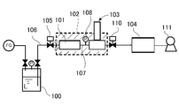
- this type of liquid source vaporizing and supplying apparatus stores a liquid source L such as TEOS (Tetraethyl orthosilicate) in a liquid storage tank 100 and pressurizes the liquid storage tank 100 with an inert gas FG.
- the liquid raw material L in the liquid storage tank 100 is extruded at a constant pressure by pressurizing the inert gas FG and supplied to the vaporizer 101, and heated in the vaporizer 101 by heating means 102 such as a jacket heater.
- the liquid raw material L is vaporized, and the vaporized gas is controlled to a predetermined flow rate by the flow rate control device 103 and supplied to the semiconductor manufacturing apparatus 104.
- reference numeral 110 denotes a stop valve
- reference numeral 111 denotes a vacuum pump.
- a control valve 105 for controlling the supply of the liquid material L to the vaporizer 101 is provided in the supply path 106 to the vaporizer 101, and the vaporizer
- the pressure detector 108 for detecting the pressure of the gas in the gas flow path 107 communicating with the flow rate control device 103 is disposed, and the gas pressure in the vaporizer 101 is monitored by the pressure detector 108.
- the control valve 105 is opened for a predetermined time and then closed to supply a predetermined amount of liquid raw material into the vaporizer 101. Then, the control is repeated so that the liquid source L in the vaporizer 101 decreases again due to vaporization and the control valve 105 is opened for a predetermined time and then closed when the detected pressure reaches a predetermined value.
- the main object of the present invention is to provide a vaporization supply device that can solve the problem that the gas flow path leading from the vaporizer to the flow rate control device is filled with the liquid raw material.
- a vaporization supply device includes a vaporizer that heats and vaporizes a liquid, a flow rate control device that controls a flow rate of a gas sent from the vaporizer, and a vaporizer supplied to the vaporizer.
- a first control valve interposed in the liquid supply path, a pressure detector for detecting the pressure of gas vaporized by the vaporizer and sent to the flow rate control device, and a liquid exceeding a predetermined amount in the vaporizer
- a liquid detection unit for measuring the parameters of the first control valve and the liquid control unit for controlling the first control valve to supply a predetermined amount of liquid to the vaporizer based on the pressure value detected by the pressure detector.
- a control device that controls to close the first control valve when the liquid flowing into the vaporizer exceeding a predetermined amount is detected.
- the apparatus further comprises a second control valve interposed in a gas flow path between the vaporizer and the flow rate control device, wherein the control device has a liquid detection unit exceeding a predetermined amount in the vaporizer.
- the first control valve is closed and the second control valve is closed.
- a vaporization supply apparatus includes a vaporizer that heats and vaporizes a liquid, a flow rate control apparatus that controls a flow rate of a gas sent from the vaporizer, and the vaporizer.
- a first control valve interposed in a liquid supply path to the liquid, a pressure detector for detecting the pressure of gas vaporized by the vaporizer and sent to the flow rate control device, the vaporizer, and the flow rate control device
- a second control valve interposed in the gas flow path between the gas detector, a liquid detector for measuring a liquid parameter exceeding a predetermined amount in the vaporizer, and the vaporization based on a pressure value detected by the pressure detector.
- the first control valve is controlled so as to supply a predetermined amount of liquid to the vaporizer, and the second control valve is closed when the liquid detection unit detects liquid flowing into the vaporizer exceeding the predetermined amount.
- a control device for controlling .
- the liquid detector can be a temperature detector.
- the liquid detector can be a liquid level gauge.
- the liquid detection unit can be a load cell.
- the vaporizer may include a vaporization chamber, and the liquid detector may be disposed in the vaporization chamber.
- the vaporizer may include a vaporization chamber and a gas heating chamber communicating with the vaporization chamber, and the liquid detection unit may be disposed in the gas heating chamber.
- the liquid detection unit measures the parameter of the liquid raw material exceeding a predetermined amount in the vaporizer, and the liquid detection unit passes the liquid flowing into the vaporizer exceeding the predetermined amount. By closing the first control valve when detected, supply of excess liquid material to the vaporizer can be stopped, and intrusion of the liquid material into the gas channel can be prevented.
- the liquid detection unit detects the liquid flowing into the vaporizer exceeding the predetermined amount
- the first control valve is closed, so that the gas supply to the flow control device is performed when the raw material liquid in the vaporizer is exhausted. Since it stops, it can be confirmed that the pressure detector has an abnormality due to product life or aging deterioration.
- the liquid detection unit detects a liquid material exceeding a predetermined amount in the vaporizer
- the liquid control material is prevented from flowing out from the vaporizer by closing the second control valve, and the liquid material enters the gas flow path. Can be prevented in advance.
- the temperature of the portion decreases.
- the liquid raw material exceeding the predetermined amount in the vaporizer can be detected.
- the weight of the liquid in the vaporizer increases. By doing so, the liquid raw material exceeding the predetermined amount in the vaporizer can be detected.
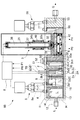
- FIG. 1 shows a first embodiment of a vaporization supply apparatus according to the present invention.
- the vaporization supply device 1 ⁇ / b> A includes a vaporizer 2 that heats and vaporizes the liquid raw material L, a flow rate control device 3 that controls the flow rate of the gas G delivered from the vaporizer 2, and the vaporizer 2.
- the liquid detector 7A that measures a parameter of the liquid material L exceeding a predetermined amount in 2 and a first amount so as to supply a predetermined amount of the liquid material L to the vaporizer 2 based on the pressure value detected by the pressure detector 6.
- a control device 8 that controls the control valve 5 and controls the first control valve 5 to be closed when the liquid detection unit 7A detects the liquid.
- the vaporizer 2 includes a main body 2A formed of stainless steel.
- the main body 2A is wrapped by heating means H such as a jacket heater for heating indicated by phantom lines.
- the main body 2A is configured by connecting a first block body 2a, a second block body 2b, and a third block body 2c.
- a liquid supply port 2a1 is formed at the top, and a vaporization chamber 2a2 is formed inside.
- the second block body 2b is formed with a first gas heating chamber 2b1 communicating with the upper part of the vaporization chamber 2a2 of the first block body 2a.
- a second gas heating chamber 2c1 communicating with the first gas heating chamber 2b1 is formed inside, and a gas discharge port 2c2 is formed in the upper part.
- columnar heating promotion bodies 2b3 and 2c3 are installed in a cylindrical space, and the gap between the cylindrical space and the heating promotion bodies 2b3 and 2c3 is a gas flow. It is a road.
- Gaskets 9 and 10 with through holes are interposed in the gas communication portions between the first block body 2a and the second block body 2b and between the second block body 2b and the third block body 2c. Gas pulsation is prevented when gas passes through the through holes of the through holes 9 and 10.
- the preheating block 11 of the liquid raw material L is connected to the first block 2a.
- the preheating block 11 has a liquid inflow port 12 connected to a side surface, a liquid storage chamber 13 communicating with the liquid inflow port 12 is formed inside, and a liquid outlet 14 communicating with the liquid storage chamber 13 is formed on the upper surface.
- the preheating block body 11 is a heating means such as a jacket heater for storing the liquid raw material L pumped at a predetermined pressure from a liquid storage tank (see reference numeral 100 in FIG. 8) outside the figure in the liquid storage chamber 13. Preheat with H.
- the first control valve 5 is fixed so as to straddle the upper surfaces of the first block body 2a and the preheating block body 11.
- the first control valve 5 opens and closes or adjusts the opening of the supply passage 4 that connects the liquid outlet 14 of the preheating block 11 and the liquid supply port 2a1 of the first block 2a to the vaporizer 2.
- the supply amount of the liquid raw material L is controlled.
- an air-driven valve that controls opening and closing of the valve body 5a using air pressure is used.
- the liquid supply port 2a1 of the first block body 2a is provided with a gasket 15 having pores formed therein, and the amount of supply into the vaporization chamber 2a2 is adjusted by passing a liquid raw material through the pores of the gasket 15. ing.
- the illustrated flow control device 3 is a known flow control device called a high-temperature compatible pressure flow control device. 1 and 2, the flow control device 3 includes a valve block 31, a gas flow path 32 formed in the valve block 31, and a metal diaphragm valve element 33 interposed in the gas flow path 32.
- a cylindrical guide member 34 fixedly erected on the valve block 31, a valve stem case 35 slidably inserted into the cylindrical guide member 34, and a hole 35 a formed in the lower portion of the valve stem case 35.
- a bridge 36 that is pressed and fixed to the valve block 31 by a cylindrical guide member 34, a heat dissipation spacer 37 and a piezoelectric drive element 38 that are housed in the valve rod case 35 and supported by the bridge 36, a valve A rod receiver 35b that protrudes from the outer periphery of the rod case 35 and extends through a hole 34a formed in the cylindrical guide member 34; a housing 39 that is mounted on the rod receiver 35b; and an upper end portion of the cylindrical guide member 34 Micropores are formed by the formed flange 34b, the coil spring 40 disposed in a compressed state between the flange 34b and the casing 39, and the gas flow path 32 on the downstream side of the metal diaphragm valve body 33.
- the perforated thin plate 41 and a flow rate control pressure detector 42 for detecting the pressure in the gas flow path 32 between the metal diaphragm valve element 33 and the perforated thin plate 41 are provided.
- the heat dissipation spacer 37 is formed of an invar material or the like, and prevents the piezoelectric driving element 38 from reaching the heat resistant temperature or higher even when a high-temperature gas flows through the gas flow path 32.
- the piezoelectric drive element 38 When the piezoelectric drive element 38 is not energized, the valve rod case 35 is pushed downward in FIG. 2 by the coil spring 40, and the metal diaphragm valve element 33 contacts the valve seat 31a as shown in FIG. Closed.
- the piezoelectric drive element 38 When the piezoelectric drive element 38 is energized, the piezoelectric drive element 38 expands, and when the valve rod case 35 is lifted upward in FIG. 2 against the elastic force of the coil spring 40, the metal diaphragm valve element 33 is restored to its original elasticity by the self-elastic force.
- the gas channel 32 is opened by returning to the inverted dish shape.
- the flow rate control device 3 detects the gas pressure at least upstream of the perforated thin plate 41 by a flow rate control pressure detector 42, and the metal interposed in the gas flow path 32 by the piezoelectric drive element 38 based on the detected pressure signal.
- the flow rate is controlled by opening and closing the diaphragm valve element 33.
- the perforated thin plate 41 is an orifice plate in which an orifice is formed.
- the hole of the perforated thin plate 41 is not limited to the orifice, and may be of any structure that restricts fluid.
- the spacer block 50 is connected to the third block body 2c, and the valve block 31 is connected to the spacer block 50.
- the gas flow path 52 in the flow path block 51 fixed so as to straddle the third block body 2c and the spacer block 50 is the second gas heating chamber 2c1 which is the gas flow path of the third block body 2c and the spacer block.
- the 50 gas flow paths 50a are communicated with each other.
- the gas flow path 50 a of the spacer block 50 communicates with the gas flow path 32 of the valve block 31.
- a pressure detector 6 is provided at a position upstream of the metal diaphragm valve body 33 in the gas flow path 32 of the valve block 31, and the pressure of the gas vaporized by the vaporizer 2 and sent to the flow rate control device 3 is detected by the pressure detector 6.
- the signal (P0) of the pressure value detected by the pressure detector 6 is always sent to the control device 8 and monitored.
- the controller 8 controls the first control valve. A predetermined amount of the liquid raw material L is supplied to the vaporizing chamber 2a2 by closing 5 after being opened for a predetermined time.
- the liquid raw material L When a predetermined amount of the liquid raw material L is supplied into the vaporizing chamber 2a2, the liquid raw material L is vaporized, whereby the gas pressure in the vaporizer 2 rises again, and then the liquid raw material L decreases, so that the vaporizer 2 again.
- the first control valve 5 When the internal pressure of the vaporizer 2 reaches the set value, the first control valve 5 is opened again for a predetermined time and then closed as described above. With such a control sequence, a predetermined amount of liquid material is sequentially replenished to the vaporizing chamber 2a2.
- the maximum water level of the liquid raw material L supplied to the vaporizing chamber 2a2 is set in advance, and the predetermined amount of the liquid raw material L supplied to the vaporizing chamber 2a2 is set according to the maximum water level.
- the water level of the liquid raw material L in the vaporizing chamber 2a2 shown in FIG. 1 indicates the set maximum water level.
- a stop valve 56 is provided in the gas flow path 55 on the downstream side of the flow control device 3.
- the vaporization supply apparatus 1A of the first embodiment is a temperature detector that measures and monitors the temperature in the first gas heating chamber 2b1 as the liquid detection unit 7A that measures the parameter of the liquid material exceeding a predetermined amount in the vaporizer 2.
- a known temperature detector such as a platinum resistance temperature detector, a thermocouple, a thermistor, or an infrared thermometer can be used as the temperature detector constituting the liquid detection unit 7A.
- a protective tube type platinum resistance temperature detector in which a platinum resistance temperature detector is inserted into a protection tube is used.
- the temperature of the liquid raw material L in the vaporizing chamber 2a2 is maintained at 185 ° C.
- the gas temperature in the first gas heating chamber 2b1 is maintained at 195 ° C. If the liquid raw material L overflows from the vaporization chamber 2a2 and flows into the first gas heating chamber 2b1, and the liquid raw material L comes into contact with the temperature detector constituting the liquid detection unit 7A, the measurement temperature of the temperature detector is reached. It is possible to detect that the liquid raw material has flowed into the first gas heating chamber 2b1 due to the decrease in.
- the control device 8 constantly monitors the detection temperature from the temperature detector that constitutes the liquid detection unit 7A, and determines that the liquid raw material L has flowed into the first gas heating chamber 2b1 when the temperature has dropped.
- the first control valve 5 is closed. At this time, even if the detection signal of the pressure detector 6 falls below the set value, the control device 8 is programmed to close the first control valve 5.
- the first control valve 5 is immediately closed. Thereby, when the liquid raw material L flows into the first gas heating chamber 2b1, even if the detected pressure value is lower than the set value due to some accident such as the malfunction of the pressure detector 6, the first control valve Since 5 is immediately closed without being opened, it is possible to prevent a problem that the gas flow path 32 from the vaporizer 2 to the flow rate control device 3 is filled with the liquid raw material.
- the liquid detector 7A detects the liquid raw material L and closes the first control valve 5
- the liquid raw material L in the vaporizer 2 is evaporated and disappears, and the supply of the raw material gas to the flow rate control device 3 is stopped. . Therefore, in this case, it is found that an abnormality has occurred in the pressure detector 6, for example, an abnormality due to product life or deterioration over time.
- the temperature detector that constitutes the liquid detection unit 7A is not limited to the first gas heating chamber 2b1, but can be disposed in the second gas heating chamber 2c1, or in the upper space from the set maximum water level of the vaporization chamber 2a2. You can also.
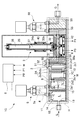
- FIG. 3 shows a second embodiment of the vaporization supply apparatus according to the present invention.
- the vaporization supply apparatus 1B according to the second embodiment is a liquid level gauge in which a liquid detection unit 7B that measures a parameter of a liquid material exceeding a predetermined amount in the vaporizer 2 measures a change in the liquid level in the vaporizer 2.
- a point is mainly different from the said 1st Embodiment, and another structure is the same as that of the said 1st Embodiment.
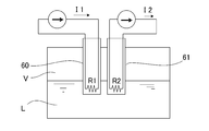
- a thermal liquid level gauge using the fact that the heat dissipation constant differs between the liquid phase and the gas phase. It can be used suitably.
- the thermal liquid level gauge is provided with two protective tubes 60 and 61 each enclosing a temperature measuring resistor R1 and R2 such as platinum, and one temperature measuring resistor R1 is provided with a temperature measuring resistor R1.
- a relatively large constant current I1 heating current
- I2 current for measuring ambient temperature
- the resistance temperature detector R1 that has passed a large current I1 generates heat.
- the heat dissipation constant when the resistance temperature detector is in the liquid phase L is the heat dissipation constant when the resistance temperature detector is in the gas phase V. Therefore, the temperature of the resistance temperature detector when it is in the gas phase V becomes higher than that when it is in the liquid phase.
- the resistance temperature sensor in the gas phase has a resistance value higher than the resistance resistance value in the liquid phase, and therefore, the voltage output of the resistance temperature detector R1 through which a large current flows, By observing the difference from the voltage output of the resistance temperature detector R2 through which a minute current flows, it is possible to determine whether the resistance temperature detector is above or below the liquid surface. That is, when the difference is small, it can be determined that the resistance temperature detector is below the liquid level, and when the difference is large, the resistance temperature detector is above the liquid level.
- FIG. 4 shows an example of the liquid level detection circuit.
- a constant current is supplied from the power source Vcc to the resistance temperature detectors R1 and R2 via the constant current circuits S1 and S2.
- a small current having a magnitude that can be ignored while the ambient temperature can be measured flows to the resistance temperature detector R2, and the current resistance R1 has a current value larger than that of the resistance temperature detector R2.
- the constant current circuit S1 is set so that a larger current flows than the constant current circuit S2 so that a relatively large current flows in order to heat the resistance temperature detector R1 to a high temperature.
- the terminal voltage V1 of the resistance temperature detector R1 and the terminal voltage V2 of the resistance temperature detector R2 are input to the inverting input and the non-inverting input of the differential amplifier circuit D, respectively.
- a voltage signal corresponding to the difference voltage V2 (V1-V2) is input to the comparator C.
- the comparator C compares the reference voltage V3 set by the voltage dividing resistors R3 and R4 with the
- the temperature increase of the resistance temperature detector R1 relative to the ambient temperature is smaller than the temperature increase in the gas phase.
- the output voltage from the operational amplification circuit D corresponding to the difference from the voltage signal of the magnitude corresponding to the ambient temperature emitted from the resistance temperature detector R2 also in the liquid phase becomes smaller than the reference voltage, and the comparator The output of C becomes low level.
- the temperature rise with respect to the ambient temperature becomes the temperature rise in the gas phase, so that the temperature measurement resistor R2 is also emitted from the gas phase.
- the output voltage of the differential amplifier circuit D corresponding to the difference from the voltage signal having a magnitude corresponding to the ambient temperature becomes higher than the reference voltage, and the output of the comparator C becomes high level.
- the resistance thermometers R1, R2 are in the gas phase, and when the output of the comparator C is low, the resistance thermometers R1, R2 are in the liquid phase. Determined.
- the resistance values of the resistance temperature detectors R1 and R2 can be obtained from the current values I1 and I2 according to Ohm's law, and if the resistance values of the resistance temperature detectors R1 and R2 are known. If the rate of resistance change with respect to the temperature of the resistance thermometers R1, R2 is known, the temperature of the resistance thermometers R1, R2 can be derived.
- the liquid level detection circuit instead of comparing the voltage outputs of the resistance temperature detectors R1 and R2, it can be determined by comparing the resistance values of the resistance temperature detectors R1 and R2, or It can also be determined by measuring the temperature of the resistance temperature detectors R1 and R2 from the respective resistance values using the rate of resistance change with respect to the temperature of the resistors R1 and R2 and comparing the temperatures.
- the resistance value is 100 ⁇ at 0 ° C., and the resistance value increases by 0.39 ⁇ for every 1 ° C. increase.
- the two protective tubes 60 and 61 of the liquid level gauge constituting the liquid detection unit 7B are arranged in the first gas heating chamber 2b1. It is installed.
- the heating promoting body 2b3 is shorter than that in the first embodiment.
- a platinum resistance temperature detector can be suitably used, but other known resistance temperature detectors can also be used.
- the protective tubes 60 and 61 are installed in the vertical direction in the second embodiment, but can also be installed in the horizontal direction.
- the control device 8 controls the pressure detector 6 in the same manner as in the first embodiment. Regardless of the detected pressure value from, the first control valve 5 is controlled to close.
- the liquid level meter constituting the liquid detection unit 7B is not limited to the first gas heating chamber 2b1, but may be provided in the vaporization chamber 2a2 or the second gas heating chamber 2c1. Further, the liquid level gauge is not limited to a thermal liquid level gauge, and a laser liquid level gauge, an ultrasonic liquid level gauge, and other known liquid level gauges may be employed. In the present invention, the “measurement” using the liquid level gauge measures the change in the liquid level of the liquid raw material L from the maximum set water level to the detection level of the protective tubes 60 and 61 as in the second embodiment. In addition to the case, the case of measuring the distance between the liquid level of the liquid raw material L and the level gauge is included.
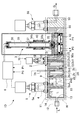
- the vaporization supply apparatus 1C according to the third embodiment differs from the first embodiment in that the liquid detection unit 7C that measures the parameter of the liquid material exceeding the predetermined amount in the vaporizer 2 is a load cell that measures the weight.
- the configuration is the same as in the first embodiment.
- a plate-shaped load cell incorporating a piezoelectric element can be adopted as the load cell constituting the liquid detection unit 7C, and is installed at the bottom of the first gas heating chamber 2b1.
- the heating accelerator 2b3 provided in the first gas heating chamber 2b1 of the first embodiment is omitted.
- the detection weight of the liquid detection unit 7C configured by the load cell increases, and it is detected that the liquid material L has flowed into the first gas heating chamber 2b1.
- the liquid detector 7C configured by a load cell detects the liquid raw material L that has flowed into the first gas heating chamber 2b1
- the control device 8 detects the detected pressure value from the pressure detector 6 as in the first embodiment. Regardless, the first control valve 5 is controlled to be closed.
- the load cell constituting the liquid detection unit 7 is not limited to the first gas heating chamber 2b1, but may be disposed on the bottom of the vaporization chamber 2a2 or the bottom of the second gas heating chamber 2c1.
- the vaporization supply device 1D of the fourth embodiment includes a second control valve 70 interposed in the gas flow path 52 between the vaporizer 2 and the flow rate control device 3 instead of the flow path block 51 of the first embodiment. ing.
- the control device 8 controls the second control valve 70 to be closed when the liquid detector 7A detects the liquid raw material L.
- control device 8 closes the first control valve 5 regardless of the detected pressure of the pressure detector 6 as in the first embodiment, when the liquid detector 7A detects the liquid raw material L. That is, in this case, when the liquid detection unit 7A detects the liquid raw material L, the control device 8 performs control so that both the first control valve 5 and the second control valve 70 are immediately closed.
- the control device 8 when the liquid detection unit 7A detects the liquid raw material L, the control device 8 does not send a control command based on the detection signal of the liquid detection unit 7A to the first control valve 5, and the second Control is performed so that only the control valve 70 is closed. That is, in this case, the detection signal of the liquid detection unit 7 ⁇ / b> A is used only for opening / closing control of the second control valve 70. In this case, the first control valve 5 is controlled in the same manner as in the past based on the detection signal of the pressure detector 6.
- the second control valve 70 is arranged in the downstream portion of the vaporizer 2 so that when there is an inflow exceeding the set limit of the liquid raw material L into the vaporizer 2, the gas flow outside the vaporizer 2 It is possible to prevent the liquid raw material L from flowing into the path 32.
- the liquid detector 7A using the temperature detector of the first embodiment is adopted, but instead of the temperature detector, the liquid detector 7B configured by the liquid level gauge of the second embodiment.
- the liquid detection unit 7C configured by the load cell of the third embodiment can be employed.
- the temperature, the liquid level, and the weight are exemplified as the liquid parameters measured by the liquid detection unit.
- the liquid parameters measured by the liquid detection unit are stored in the vaporizer. Other parameters may be used as long as they can detect the liquid that has flowed beyond the fixed amount.
- Vaporization supply device Vaporizer 2a2 Vaporization chamber 2b1 First gas heating chamber 2c1 Second gas heating chamber 3
- Flow rate control device 5
- First control valve 6
- Control device 70 Second control valve
Landscapes
- Chemical & Material Sciences (AREA)
- Chemical Kinetics & Catalysis (AREA)
- Organic Chemistry (AREA)
- General Chemical & Material Sciences (AREA)
- Engineering & Computer Science (AREA)
- Materials Engineering (AREA)
- Mechanical Engineering (AREA)
- Metallurgy (AREA)
- Chemical Vapour Deposition (AREA)
- Filling Or Discharging Of Gas Storage Vessels (AREA)
- Feeding, Discharge, Calcimining, Fusing, And Gas-Generation Devices (AREA)
Abstract
Description
2 気化器
2a2 気化室
2b1 第1ガス加熱室
2c1 第2ガス加熱室
3 流量制御装置
5 第1制御弁
6 圧力検出器
7A,7B,7C 液体検知部
8 制御装置
70 第2制御弁
Claims (8)
- 液体を加熱して気化させる気化器と、
前記気化器から送出されるガスの流量を制御する流量制御装置と、
前記気化器への液体の供給路に介在された第1制御弁と、
前記気化器で気化され前記流量制御装置に送られるガスの圧力を検出するための圧力検出器と、
前記気化器内の所定量を超える液体のパラメータを測定する液体検知部と、
前記圧力検出器の検出した圧力値に基づいて前記気化器に所定量の液体を供給するように前記第1制御弁を制御するとともに、前記液体検知部が所定量を超えて前記気化器内に流入した液体を検知した時には前記第1制御弁を閉じるように制御する制御装置と、
を備えることを特徴とする気化供給装置。 - 前記気化器と前記流量制御装置の間のガス流路に介在された第2制御弁を更に備え、
前記制御装置は、前記液体検知部が所定量を超えて前記気化器内に流入した液体を検知した時に、前記第1制御弁を閉じるとともに前記第2制御弁を閉じるように制御することを特徴とする、請求項1に記載の気化供給装置。 - 液体を加熱して気化させる気化器と、
前記気化器から送出されるガスの流量を制御する流量制御装置と、
前記気化器への液体の供給路に介在された第1制御弁と、
前記気化器で気化され前記流量制御装置に送られるガスの圧力を検出するための圧力検出器と、
前記気化器と前記流量制御装置の間のガス流路に介在された第2制御弁と、
前記気化器内の所定量を超える液体のパラメータを測定する液体検知部と、
前記圧力検出器の検出した圧力値に基づいて前記気化器に所定量の液体を供給するように前記第1制御弁を制御するとともに、前記液体検知部が所定量を超えて前記気化器内に流入した液体を検知した時に前記第2制御弁を閉じるように制御する制御装置と、
を備えることを特徴とする気化供給装置。 - 前記液体検知部が温度検出器であることを特徴とする請求項1~3の何れかに記載の気化供給装置。
- 前記液体検知部が液面計であることを特徴とする請求項1~3の何れかに記載の気化供給装置。
- 前記液体検知部がロードセルであることを特徴とする請求項1~3の何れかに記載の気化供給装置。
- 前記気化器が気化室を備え、該気化室に前記液体検知部が配設されていることを特徴とする請求項1~6の何れかに記載の気化供給装置。
- 前記気化器が気化室と該気化室に連通するガス加熱室とを備え、前記ガス加熱室に前記液体検知部が配設されていることを特徴とする請求項1~6の何れかに記載の気化供給装置。
Priority Applications (3)
| Application Number | Priority Date | Filing Date | Title |
|---|---|---|---|
| CN201680007156.XA CN107532298B (zh) | 2015-04-30 | 2016-04-11 | 气化供给装置 |
| KR1020177017535A KR101962659B1 (ko) | 2015-04-30 | 2016-04-11 | 기화 공급 장치 |
| US15/565,696 US10646844B2 (en) | 2015-04-30 | 2016-04-11 | Vaporization supply apparatus |
Applications Claiming Priority (2)
| Application Number | Priority Date | Filing Date | Title |
|---|---|---|---|
| JP2015-093494 | 2015-04-30 | ||
| JP2015093494A JP6578125B2 (ja) | 2015-04-30 | 2015-04-30 | 気化供給装置 |
Publications (1)
| Publication Number | Publication Date |
|---|---|
| WO2016174832A1 true WO2016174832A1 (ja) | 2016-11-03 |
Family
ID=57199662
Family Applications (1)
| Application Number | Title | Priority Date | Filing Date |
|---|---|---|---|
| PCT/JP2016/001967 Ceased WO2016174832A1 (ja) | 2015-04-30 | 2016-04-11 | 気化供給装置 |
Country Status (6)
| Country | Link |
|---|---|
| US (1) | US10646844B2 (ja) |
| JP (1) | JP6578125B2 (ja) |
| KR (1) | KR101962659B1 (ja) |
| CN (1) | CN107532298B (ja) |
| TW (1) | TWI632609B (ja) |
| WO (1) | WO2016174832A1 (ja) |
Cited By (7)
| Publication number | Priority date | Publication date | Assignee | Title |
|---|---|---|---|---|
| KR20190140001A (ko) | 2017-07-25 | 2019-12-18 | 가부시키가이샤 후지킨 | 유체 제어 장치 |
| KR20190140002A (ko) | 2017-07-25 | 2019-12-18 | 가부시키가이샤 후지킨 | 유체 제어 장치 |
| WO2021054135A1 (ja) * | 2019-09-19 | 2021-03-25 | 株式会社フジキン | 気化供給装置 |
| TWI741897B (zh) * | 2019-12-06 | 2021-10-01 | 日商富士金股份有限公司 | 流量控制裝置的異常檢出方法及流量監視方法 |
| KR20220029730A (ko) | 2019-08-30 | 2022-03-08 | 가부시키가이샤 후지킨 | 다이어프램 밸브 |
| WO2022075111A1 (ja) * | 2020-10-07 | 2022-04-14 | 東京エレクトロン株式会社 | 気化装置、ガス供給装置及びガス供給装置の制御方法 |
| KR20230145432A (ko) | 2021-04-01 | 2023-10-17 | 가부시키가이샤 후지킨 | 제어기 및 기화 공급 장치 |
Families Citing this family (11)
| Publication number | Priority date | Publication date | Assignee | Title |
|---|---|---|---|---|
| JP7137921B2 (ja) * | 2017-11-07 | 2022-09-15 | 株式会社堀場エステック | 気化システム及び気化システム用プログラム |
| WO2021039073A1 (ja) | 2019-08-29 | 2021-03-04 | 株式会社フジキン | 流体供給システム |
| TWI846960B (zh) * | 2019-10-04 | 2024-07-01 | 法商液態空氣喬治斯克勞帝方法研究開發股份有限公司 | 低揮發性前驅物的供應系統 |
| JP7240770B2 (ja) * | 2019-12-16 | 2023-03-16 | 株式会社フジキン | 気化供給方法及び気化供給装置 |
| JP7457522B2 (ja) * | 2020-02-20 | 2024-03-28 | 株式会社堀場エステック | 気化システム |
| WO2022022188A1 (zh) | 2020-07-27 | 2022-02-03 | 江苏菲沃泰纳米科技股份有限公司 | 原料气化装置和镀膜装置以及镀膜设备及其进料方法 |
| JP7316011B2 (ja) * | 2020-10-31 | 2023-07-27 | 株式会社フジキン | ガス供給システムおよびガス供給方法 |
| JP7577382B2 (ja) * | 2021-03-11 | 2024-11-05 | 株式会社フジキン | 気化器および気化供給装置 |
| US12323687B2 (en) * | 2021-06-11 | 2025-06-03 | Tdk Corporation | Driving mechanism |
| JP2023166664A (ja) * | 2022-05-10 | 2023-11-22 | 大陽日酸株式会社 | 半導体材料ガス供給装置 |
| KR102774123B1 (ko) * | 2023-06-02 | 2025-03-04 | 주식회사 비투지홀딩스 | 질화갈륨 단결정 성장을 위한 하이드라이드 기상 증착 장비의 갈륨 공급 장치 및 이를 포함하는 하이드라이드 기상 증착 장비 |
Citations (6)
| Publication number | Priority date | Publication date | Assignee | Title |
|---|---|---|---|---|
| JPH02261529A (ja) * | 1989-04-01 | 1990-10-24 | Tel Sagami Ltd | 液体材料気化供給装置 |
| JP2000133644A (ja) * | 1998-10-28 | 2000-05-12 | Mitsubishi Electric Corp | 半導体装置の製造装置 |
| JP2005217089A (ja) * | 2004-01-29 | 2005-08-11 | Nec Kansai Ltd | 半導体製造装置および半導体製造方法 |
| JP2009252760A (ja) * | 2008-04-01 | 2009-10-29 | Fujikin Inc | 気化器を備えたガス供給装置 |
| JP2010173660A (ja) * | 2009-01-27 | 2010-08-12 | Air Liquide Japan Ltd | 充填容器内の液体材料の供給装置および該液体材料の供給装置における充填容器内の液面管理方法 |
| JP2010180429A (ja) * | 2009-02-03 | 2010-08-19 | Fujikin Inc | 液体材料の気化供給システム |
Family Cites Families (7)
| Publication number | Priority date | Publication date | Assignee | Title |
|---|---|---|---|---|
| JP3896594B2 (ja) * | 2004-10-01 | 2007-03-22 | 株式会社ユーテック | Cvd用気化器、溶液気化式cvd装置及びcvd用気化方法 |
| JP4263206B2 (ja) * | 2005-11-15 | 2009-05-13 | 東京エレクトロン株式会社 | 熱処理方法、熱処理装置及び気化装置 |
| JP5652960B2 (ja) * | 2011-08-01 | 2015-01-14 | 株式会社フジキン | 原料気化供給装置 |
| JP5913888B2 (ja) | 2011-09-30 | 2016-04-27 | 国立大学法人東北大学 | 気化器 |
| JP2014006151A (ja) | 2012-06-25 | 2014-01-16 | Taiyo Nippon Sanso Corp | 液体材料有無検知方法 |
| JP5837869B2 (ja) | 2012-12-06 | 2015-12-24 | 株式会社フジキン | 原料気化供給装置 |
| JP5548292B1 (ja) * | 2013-05-30 | 2014-07-16 | 株式会社堀場エステック | 加熱気化システムおよび加熱気化方法 |
-
2015
- 2015-04-30 JP JP2015093494A patent/JP6578125B2/ja active Active
-
2016
- 2016-04-11 US US15/565,696 patent/US10646844B2/en active Active
- 2016-04-11 CN CN201680007156.XA patent/CN107532298B/zh not_active Expired - Fee Related
- 2016-04-11 KR KR1020177017535A patent/KR101962659B1/ko active Active
- 2016-04-11 WO PCT/JP2016/001967 patent/WO2016174832A1/ja not_active Ceased
- 2016-04-21 TW TW105112439A patent/TWI632609B/zh active
Patent Citations (6)
| Publication number | Priority date | Publication date | Assignee | Title |
|---|---|---|---|---|
| JPH02261529A (ja) * | 1989-04-01 | 1990-10-24 | Tel Sagami Ltd | 液体材料気化供給装置 |
| JP2000133644A (ja) * | 1998-10-28 | 2000-05-12 | Mitsubishi Electric Corp | 半導体装置の製造装置 |
| JP2005217089A (ja) * | 2004-01-29 | 2005-08-11 | Nec Kansai Ltd | 半導体製造装置および半導体製造方法 |
| JP2009252760A (ja) * | 2008-04-01 | 2009-10-29 | Fujikin Inc | 気化器を備えたガス供給装置 |
| JP2010173660A (ja) * | 2009-01-27 | 2010-08-12 | Air Liquide Japan Ltd | 充填容器内の液体材料の供給装置および該液体材料の供給装置における充填容器内の液面管理方法 |
| JP2010180429A (ja) * | 2009-02-03 | 2010-08-19 | Fujikin Inc | 液体材料の気化供給システム |
Cited By (21)
| Publication number | Priority date | Publication date | Assignee | Title |
|---|---|---|---|---|
| US11390951B2 (en) | 2017-07-25 | 2022-07-19 | Fujikin Incorporated | Fluid control device |
| KR20190140002A (ko) | 2017-07-25 | 2019-12-18 | 가부시키가이샤 후지킨 | 유체 제어 장치 |
| KR20190140001A (ko) | 2017-07-25 | 2019-12-18 | 가부시키가이샤 후지킨 | 유체 제어 장치 |
| US11976748B2 (en) | 2019-08-30 | 2024-05-07 | Fujikin Incorporated | Diaphragm valve |
| KR20240024359A (ko) | 2019-08-30 | 2024-02-23 | 가부시키가이샤 후지킨 | 다이어프램 밸브 |
| KR20220029730A (ko) | 2019-08-30 | 2022-03-08 | 가부시키가이샤 후지킨 | 다이어프램 밸브 |
| KR20220035485A (ko) | 2019-09-19 | 2022-03-22 | 가부시키가이샤 후지킨 | 기화 공급 장치 |
| CN114269966A (zh) * | 2019-09-19 | 2022-04-01 | 株式会社富士金 | 气化供给装置 |
| JP7577339B2 (ja) | 2019-09-19 | 2024-11-05 | 株式会社フジキン | 気化供給装置 |
| WO2021054135A1 (ja) * | 2019-09-19 | 2021-03-25 | 株式会社フジキン | 気化供給装置 |
| US11976356B2 (en) | 2019-09-19 | 2024-05-07 | Fujikin Incorporated | Vaporized feed device |
| JPWO2021054135A1 (ja) * | 2019-09-19 | 2021-03-25 | ||
| US11988543B2 (en) | 2019-12-06 | 2024-05-21 | Fujikin Incorporated | Abnormality detection method for flow rate control device, and flow rate monitoring method |
| TWI741897B (zh) * | 2019-12-06 | 2021-10-01 | 日商富士金股份有限公司 | 流量控制裝置的異常檢出方法及流量監視方法 |
| KR20220043208A (ko) | 2019-12-06 | 2022-04-05 | 가부시키가이샤 후지킨 | 유량 제어 장치의 이상 검지 방법 및 유량 감시 방법 |
| JP2022061803A (ja) * | 2020-10-07 | 2022-04-19 | 東京エレクトロン株式会社 | 気化装置、ガス供給装置及びガス供給装置の制御方法 |
| WO2022075111A1 (ja) * | 2020-10-07 | 2022-04-14 | 東京エレクトロン株式会社 | 気化装置、ガス供給装置及びガス供給装置の制御方法 |
| JP7589890B2 (ja) | 2020-10-07 | 2024-11-26 | 株式会社フジキン | 気化装置、ガス供給装置及びガス供給装置の制御方法 |
| TWI896767B (zh) * | 2020-10-07 | 2025-09-11 | 日商富士金股份有限公司 | 氣化裝置、氣體供給裝置及氣體供給裝置之控制方法 |
| KR20230145432A (ko) | 2021-04-01 | 2023-10-17 | 가부시키가이샤 후지킨 | 제어기 및 기화 공급 장치 |
| US12398819B2 (en) | 2021-04-01 | 2025-08-26 | Fujikin Incorporated | Controller and vaporization supply device |
Also Published As
| Publication number | Publication date |
|---|---|
| CN107532298A (zh) | 2018-01-02 |
| TWI632609B (zh) | 2018-08-11 |
| US20180071702A1 (en) | 2018-03-15 |
| KR101962659B1 (ko) | 2019-03-27 |
| TW201705279A (zh) | 2017-02-01 |
| KR20170088416A (ko) | 2017-08-01 |
| JP6578125B2 (ja) | 2019-09-18 |
| JP2016211021A (ja) | 2016-12-15 |
| CN107532298B (zh) | 2019-07-26 |
| US10646844B2 (en) | 2020-05-12 |
Similar Documents
| Publication | Publication Date | Title |
|---|---|---|
| JP6578125B2 (ja) | 気化供給装置 | |
| JP6212467B2 (ja) | 液面計及び液体原料気化供給装置 | |
| TWI437402B (zh) | Pressure flow control device | |
| TWI628717B (zh) | 加熱汽化系統和加熱汽化方法 | |
| KR102097344B1 (ko) | 질량 유량의 측정 방법, 당해 방법을 사용하는 열식 질량 유량계 및 당해 열식 질량 유량계를 사용하는 열식 질량 유량 제어 장치 | |
| TWI521190B (zh) | 質流控制器 | |
| JP2016211021A5 (ja) | ||
| US20140216339A1 (en) | Raw material vaporizing and supplying apparatus | |
| US10274356B2 (en) | Liquid level detection circuit, liquid level meter, container provided with liquid level meter, and vaporizer using container | |
| US10345130B2 (en) | Airflow sensor with thermal conductivity and diffusivity sensing | |
| KR102894024B1 (ko) | 기화 공급 장치 | |
| KR20160122732A (ko) | 압력 둔감형 자기 검증 질량 유량 컨트롤러를 제공하는 시스템 및 방법 | |
| US11550341B2 (en) | Mass flow control system, and semiconductor manufacturing equipment and vaporizer including the system | |
| KR20260051273A (ko) | 질량 유량 제어기의 자동 자체 교정을 위한 방법 및 장치 | |
| CN113518899A (zh) | 流量测量装置、具备流量测量装置的燃气表及用于燃气表的流量测量装置单元 | |
| JP2016017844A (ja) | 流量計および補正値算出方法 |
Legal Events
| Date | Code | Title | Description |
|---|---|---|---|
| 121 | Ep: the epo has been informed by wipo that ep was designated in this application |
Ref document number: 16786112 Country of ref document: EP Kind code of ref document: A1 |
|
| ENP | Entry into the national phase |
Ref document number: 20177017535 Country of ref document: KR Kind code of ref document: A |
|
| WWE | Wipo information: entry into national phase |
Ref document number: 15565696 Country of ref document: US |
|
| NENP | Non-entry into the national phase |
Ref country code: DE |
|
| 122 | Ep: pct application non-entry in european phase |
Ref document number: 16786112 Country of ref document: EP Kind code of ref document: A1 |