WO2016170840A1 - 駆動制御装置 - Google Patents
駆動制御装置 Download PDFInfo
- Publication number
- WO2016170840A1 WO2016170840A1 PCT/JP2016/055278 JP2016055278W WO2016170840A1 WO 2016170840 A1 WO2016170840 A1 WO 2016170840A1 JP 2016055278 W JP2016055278 W JP 2016055278W WO 2016170840 A1 WO2016170840 A1 WO 2016170840A1
- Authority
- WO
- WIPO (PCT)
- Prior art keywords
- control
- processing unit
- control processor
- signal
- diagnosis
- Prior art date
- Legal status (The legal status is an assumption and is not a legal conclusion. Google has not performed a legal analysis and makes no representation as to the accuracy of the status listed.)
- Ceased
Links
Images



Classifications
-
- F—MECHANICAL ENGINEERING; LIGHTING; HEATING; WEAPONS; BLASTING
- F04—POSITIVE - DISPLACEMENT MACHINES FOR LIQUIDS; PUMPS FOR LIQUIDS OR ELASTIC FLUIDS
- F04B—POSITIVE-DISPLACEMENT MACHINES FOR LIQUIDS; PUMPS
- F04B49/00—Control, e.g. of pump delivery, or pump pressure of, or safety measures for, machines, pumps, or pumping installations, not otherwise provided for, or of interest apart from, groups F04B1/00 - F04B47/00
- F04B49/06—Control using electricity
- F04B49/065—Control using electricity and making use of computers
-
- G—PHYSICS
- G06—COMPUTING OR CALCULATING; COUNTING
- G06F—ELECTRIC DIGITAL DATA PROCESSING
- G06F11/00—Error detection; Error correction; Monitoring
- G06F11/07—Responding to the occurrence of a fault, e.g. fault tolerance
- G06F11/0703—Error or fault processing not based on redundancy, i.e. by taking additional measures to deal with the error or fault not making use of redundancy in operation, in hardware, or in data representation
- G06F11/0751—Error or fault detection not based on redundancy
- G06F11/0754—Error or fault detection not based on redundancy by exceeding limits
- G06F11/0757—Error or fault detection not based on redundancy by exceeding limits by exceeding a time limit, i.e. time-out, e.g. watchdogs
-
- G—PHYSICS
- G05—CONTROLLING; REGULATING
- G05B—CONTROL OR REGULATING SYSTEMS IN GENERAL; FUNCTIONAL ELEMENTS OF SUCH SYSTEMS; MONITORING OR TESTING ARRANGEMENTS FOR SUCH SYSTEMS OR ELEMENTS
- G05B23/00—Testing or monitoring of control systems or parts thereof
- G05B23/02—Electric testing or monitoring
- G05B23/0205—Electric testing or monitoring by means of a monitoring system capable of detecting and responding to faults
- G05B23/0218—Electric testing or monitoring by means of a monitoring system capable of detecting and responding to faults characterised by the fault detection method dealing with either existing or incipient faults
-
- G—PHYSICS
- G05—CONTROLLING; REGULATING
- G05B—CONTROL OR REGULATING SYSTEMS IN GENERAL; FUNCTIONAL ELEMENTS OF SUCH SYSTEMS; MONITORING OR TESTING ARRANGEMENTS FOR SUCH SYSTEMS OR ELEMENTS
- G05B9/00—Safety arrangements
- G05B9/02—Safety arrangements electric
-
- G—PHYSICS
- G06—COMPUTING OR CALCULATING; COUNTING
- G06F—ELECTRIC DIGITAL DATA PROCESSING
- G06F11/00—Error detection; Error correction; Monitoring
- G06F11/07—Responding to the occurrence of a fault, e.g. fault tolerance
-
- G—PHYSICS
- G06—COMPUTING OR CALCULATING; COUNTING
- G06F—ELECTRIC DIGITAL DATA PROCESSING
- G06F11/00—Error detection; Error correction; Monitoring
- G06F11/07—Responding to the occurrence of a fault, e.g. fault tolerance
- G06F11/0796—Safety measures, i.e. ensuring safe condition in the event of error, e.g. for controlling element
-
- G—PHYSICS
- G05—CONTROLLING; REGULATING
- G05B—CONTROL OR REGULATING SYSTEMS IN GENERAL; FUNCTIONAL ELEMENTS OF SUCH SYSTEMS; MONITORING OR TESTING ARRANGEMENTS FOR SUCH SYSTEMS OR ELEMENTS
- G05B2219/00—Program-control systems
- G05B2219/20—Pc systems
- G05B2219/26—Pc applications
Definitions
- the present invention relates to a drive control device including a watchdog timer.
- the CPU operation abnormality detected by the monitoring IC is limited to a specific abnormality such as an operation abnormality of the torque monitor unit and the signal abnormality diagnosis unit.
- the technique disclosed in Patent Document 1 is that an ALU (Arithmetic Logic Unit) operation error, a data path operation error, a register operation error, an internal RAM operation error that may occur in the operation of the CPU.
- ALU Arimetic Logic Unit
- Measures using a watchdog timer are available as a means of dealing with a wide range of operational abnormalities that can occur in the CPU.
- a pulse signal is periodically supplied from the CPU to the watchdog timer to reset the watchdog timer. If an abnormal operation occurs in the CPU and the pulse signal is not supplied for a predetermined time, the watchdog timer outputs a reset signal to the CPU and causes the CPU to execute a reset process.
- a watchdog timer is provided as in Patent Document 2, but when the supply of a regular watchdog timer clear signal from the CPU is interrupted, the watchdog timer Is not operating normally, and an error notification is sent to the host system.
- the technique disclosed in Patent Document 2 described above has a problem that no countermeasure is taken when the reset function of the CPU that is the control processor does not operate normally even if a reset signal is given.
- the technique disclosed in Patent Document 2 described above has a problem that even if the reset function of the CPU that is the control processor works normally, there is no guarantee that the CPU after the reset operates normally.
- the techniques disclosed in Patent Documents 2 and 3 described above have a problem that it is difficult to maintain the drive control system in a safe state when the operation of the watchdog timer itself becomes abnormal.
- the present invention has been made in view of the circumstances described above, and a first object of the present invention is not to eliminate even if an operation abnormality or a reset of the control processor is performed such that the reset of the control processor does not work normally.
- An object of the present invention is to provide a drive control device capable of maintaining a drive control system in a safe state even when a malfunction occurs in a control processor.
- a second object of the present invention is to provide a drive control device capable of maintaining a drive control system in a safe state even in a situation where an operation abnormality occurs in the watchdog timer itself.
- the present invention provides a control processor that generates a control signal, and resets the time value according to a reset signal supplied from the control processor, and after the reset, completes the time measurement of the target time, thereby Provided is a drive control device comprising a watchdog timer that continuously outputs a shut-off signal for shutting off the supply of a control signal to a device to be controlled.
- the watchdog timer when the supply of the reset signal from the control processor to the watchdog timer is interrupted, the watchdog timer continuously supplies the control signal to the device to be controlled by completing the target time measurement. Shut off. Therefore, even if an operation abnormality that prevents the reset of the control processor from operating normally or an operation abnormality that does not disappear even if the control processor is reset occurs, It is possible to prevent adverse effects and maintain the drive control system in a safe state.
- control processor has a diagnosis unit for diagnosing the operation of the control processor, and the operation range is limited as compared with a normal state when the diagnosis unit diagnoses that the operation of the control processor is abnormal.
- Safe state transition processing means for shifting the control processor to a safe state.
- the control processor is brought into a safe state.
- the drive control system can be maintained in a safe state.
- the diagnosis means repeats the diagnosis at a cycle shorter than the target time, and outputs the reset signal when the control processor is diagnosed as normal.
- the safe state transition unit shifts the control processor to the safe state before the watchdog timer outputs the shut-off signal. . Therefore, the safety of the control target device can be ensured.
- the safety state transition processing means is a control signal for setting the device to be controlled to a safe state in which the operating range is limited as compared with the normal state when the diagnosis means diagnoses an abnormality in the operation of the control processor. Are output from the control processor.
- the safety of the control target device can be ensured by limiting the operation range of the control target device.
- the safety state transition processing means stops the output of the control signal from the control processor when the diagnosis means diagnoses an abnormality in the operation of the control processor.
- the influence of the operation abnormality of the control processor can be prevented from reaching the control target device.
- the safety state transition processing means shifts the operation state of the control target device to a predetermined safety state over time when the diagnosis means diagnoses an abnormality in the operation of the control processor.
- a control signal is output from the control processor.
- the drive state of the control target device can be gradually shifted to a safe state with time. Therefore, it is possible to prevent the operation of the control target apparatus from becoming unstable.
- control processor includes communication means for notifying the host controller of an abnormal operation of the control processor when the diagnostic means diagnoses an abnormal operation of the control processor.
- the host controller can recognize an abnormal operation of the control processor.
- the safe state transition processing means places the control processor in a hold state when the diagnosis means diagnoses an abnormality in the operation of the control processor.
- the control processor is put in the hold state, so that the influence of the operation abnormality of the control processor can be prevented from increasing.
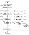
- FIG. 1 is a block diagram showing a configuration of a drive control system including a drive control device 1 according to an embodiment of the present invention. It is a flowchart which shows the processing content of the control processor 11 of the drive control apparatus 1. FIG. It is a flowchart which shows the safety function diagnostic process which the control processor 11 performs.
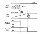
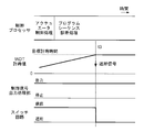
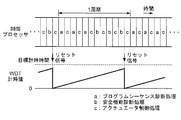
- 3 is a time chart showing a first operation example of the control processor 11; 6 is a time chart showing a second operation example of the control processor 11; 10 is a time chart showing a third operation example of the control processor 11; It is a time chart which shows the operation example of the control processor in other embodiment of this invention.
- FIG. 1 is a block diagram showing a configuration of a drive control system including a drive control apparatus 1 according to an embodiment of the present invention.
- the drive control system includes a drive control device 1, a host controller 2, a switch circuit 3, a drive circuit 4 that is a control target device of the drive control device 1, and an actuator 5.
- the host controller 2 includes a control device such as a PLC (Programmable Logic Controller) and a safety device including a safety relay.
- the host controller 2 supplies the drive control device 1 with a control command signal generated based on an operation by the user.
- the host controller 2 generates a safety signal in the drive control system when it detects the occurrence of danger such as the approach of the operator to the actuator 5 or when the emergency stop button is pressed. This is supplied to the drive control device 1.
- the host controller 2 also receives an abnormality report signal indicating an abnormality of a control processor 11 (described later) of the drive control device 1 from the drive control device 1, and executes processing corresponding to the abnormality report signal, such as generation of an alarm.
- the switch circuit 3 is provided between the drive control device 1 and the drive circuit 4.
- the switch circuit 3 normally supplies a control signal output from the drive control device 1 to the drive circuit 4. However, the switch circuit 3 is turned off when a cutoff signal is given from the drive control device 1. Shut off the supply of control signals to.
- the drive circuit 4 is a main circuit of an inverter, for example, and includes a plurality of switching elements.
- the drive circuit 4 turns on a switching element based on a control signal supplied from the drive control device 1 and supplies a drive voltage to the actuator 5 via the switching element.
- the actuator 5 is a motor, for example.
- the drive control device 1 generates a control signal based on the control command signal or the safety signal, supplies the control signal to the drive circuit 4 via the switch circuit 3, and controls the drive of the actuator 5.
- the drive control device 1 includes a control processor 11 and a watchdog timer (hereinafter abbreviated as WDT) 12.
- the WDT 12 includes a counter that counts a clock with a fixed period. When a reset signal is supplied from the control processor 11, the WDT 12 sets the clock count value (that is, the time measurement value) to zero. Further, the WDT 12 continuously supplies a cut-off signal to the switch circuit 3 when the measured value reaches a predetermined target time.
- the control processor 11 is means for generating a control signal for controlling the actuator 5 based on a control command signal or a safety signal supplied from the host controller 2.
- the control processor 11 is a CPU that incorporates a CPU core, a ROM that stores a program executed by the CPU core, and a RAM that is used as a work area by the CPU core. In FIG. 1, the CPU core, the ROM, and the RAM are not shown.
- the functions realized by the CPU core of the control processor 11 (hereinafter simply referred to as the control processor 11 for convenience of explanation) executing the program in the ROM include the communication processing unit 111 shown in FIG.
- the control unit 112, the actuator control processing unit 113, the diagnosis processing unit 114, the control signal output processing unit 115, and the safe state transition processing unit 116 can be broadly classified.
- the communication processing unit 111 is a means for receiving a control command signal and a safety signal from the host controller 2. Further, when the communication processing unit 111 receives the abnormality report signal from the safe state transition processing unit 116, the communication processing unit 111 transmits the abnormality report signal to the host controller 2, and thereafter, the control command signal and the safety signal from the host controller 2 are transmitted. Reject the reception. However, when the host controller 2 determines the content of the abnormality report signal and transmits a return command signal, the communication processing unit 111 receives this return command signal and receives the control signal and safety signal from the host controller 2. Resume.
- the command input processing unit 112 is means for delivering the control command signal and the safety signal received from the host controller 2 by the communication processing unit 111 to the actuator control processing unit 113.
- the actuator control processing unit 113 is a means for executing arithmetic processing for generating a control signal for driving and controlling the actuator 5 based on the control command signal and the safety signal.
- the actuator control processing unit 113 performs PWM (for controlling ON / OFF of each switching element of the drive circuit 4).
- PWM Pulse Width Modulation
- the actuator control processing unit 113 controls increase / decrease in the pulse width of the PWM signal that is a control signal in accordance with the control command signal and the safety signal.
- the control signal output processing unit 115 is a means for outputting the control signal generated by the actuator control processing unit 113 from the control processor 11.
- the control signal output processing unit 115 receives a stop signal from the safe state transition processing unit 116, the control signal output processing unit 115 stops outputting the control signal.
- the diagnosis processing unit 114 is a means for diagnosing whether the operation of the actuator control processing unit 113 is normal or abnormal.
- the diagnosis processing unit 114 includes a program sequence diagnosis processing unit 1141 and a safety function diagnosis processing unit 1142.
- the program sequence diagnosis processing unit 1141 is a means for diagnosing whether the operation of generating the control signal according to the control command signal among the operations of the actuator control processing unit 113 is normal or abnormal.
- the safety function diagnosis processing unit 1142 is a means for diagnosing whether the operation of generating the control signal according to the safety signal among the operations of the actuator control processing unit 113 is normal or abnormal.
- the program sequence diagnosis processing unit 1141 and the safety function diagnosis processing unit 1142 are abnormalities in the ALU, data path, register, and internal RAM in the control processor 11 used in the actuator control processor 113. Detecting an abnormality in the address calculation means, an abnormality in the interrupt processing means, an abnormality in the control logic, and an abnormality in the configuration register.
- the diagnosis processing unit 114 periodically repeats the diagnosis processing by the program sequence diagnosis processing unit 1141 and the diagnosis processing by the safety function diagnosis processing unit 1142, and the diagnosis result that the operation of the actuator control processing unit 113 is normal in both diagnosis processes. Is obtained, a reset signal is supplied to the WDT 12. Further, the safety state transition processing unit 116 outputs an abnormality signal when an abnormality in the operation of the actuator control processing unit 113 is diagnosed in the diagnosis processing by the program sequence diagnosis processing unit 1141 or the diagnosis processing by the safety function diagnosis processing unit 1142. Output to the safe state transition processing unit 116.
- This abnormality signal includes information indicating that the control processor 11 is abnormal and information indicating the content of the abnormality.
- the safety state transition processing unit 116 moves the control processor 11 to a safe state in which the operation range is limited as compared with the normal state. It functions as a state transition processing means.
- the safe state is a state in which the control processor 11 holds (a state in which the internal state is not changed) and does not generate and output a control signal.
- the abnormal state signal is received from the diagnostic processing unit 114, the safe state transition processing unit 116 outputs a stop signal to the control signal output processing unit 115 and outputs the abnormal signal to the communication processing unit 111 as an abnormality report signal. Further, the control processor 11 is brought into a hold state.
- FIG. 2 is a flowchart showing the processing contents of the control processor 11.
- the program sequence diagnosis processing unit 1141 executes the program sequence diagnosis processing.
- This program sequence diagnosis process is a process for diagnosing an operation of generating a control signal in accordance with a control command signal among the operations of the actuator control processing unit 113.
- the program sequence diagnosis processing unit 1141 determines the diagnosis result of the program sequence diagnosis processing. If the diagnosis result indicates that the operation of the actuator control processing unit 113 is abnormal, the process proceeds to step S110, and if the diagnosis result indicates that the operation of the actuator control processing unit 113 is normal, the process is performed. Advances to step S103.
- This safety function diagnosis process is a process for diagnosing an operation of generating a control signal in accordance with a safety signal among the operations of the actuator control processing unit 113.
- the safety function diagnosis processing unit 1142 determines the diagnosis result of the safety function diagnosis process. If the diagnosis result indicates that the operation of the actuator control processing unit 113 is abnormal, the process proceeds to step S110, and if the diagnosis result indicates that the operation of the actuator control processing unit 113 is normal, the process is performed. Advances to step S105.
- step S105 when proceeding to step S105, the diagnosis processing unit 114 outputs a reset signal to the WDT 12 to reset the time measured value of the WDT 12.
- step S106 the actuator control processing unit 113 executes the original actuator control processing.
- the actuator control processing unit 113 acquires a control command signal or a safety signal from the command input processing unit 112, generates a control signal based on the control command signal or the safety signal, and outputs a control signal output processing unit 115. To supply.
- step S106 When this step S106 is completed, the process returns to step S101. Thereafter, as long as the operation of the actuator control processing unit 113 is normal in both diagnosis results of the program sequence diagnosis process (step S101) and the safety function diagnosis process (step S103), steps S101 ⁇ S102 ⁇ S103 ⁇ S104 ⁇ S105 ⁇ S106 ⁇ The processing of each step is repeated in the order of S101.
- step S110 if it is determined in step S102 or S104 that the diagnosis result indicates that the operation of the actuator control processing unit 113 is abnormal, the process proceeds to step S110.
- step S ⁇ b> 110 the diagnosis processing unit 114 outputs an abnormality signal to the safe state transition processing unit 116.
- the safe state transition processing unit 116 outputs an abnormality report signal to the communication processing unit 111.
- the communication processing unit 111 transmits an abnormality report signal to the host controller 2, and thereafter refuses to receive the control command signal and the safety signal from the host controller 2.
- step S111 the safe state transition processing unit 116 performs processing for shifting to the safe state. Specifically, the safe state transition processing unit 116 outputs a stop signal to the control signal output processing unit 115. As a result, the control signal output processing unit 115 stops outputting the control signal from the actuator control processing unit 113 to the outside. Also, the safe state transition processing unit 116 stops the internal clock to the control processor 11, puts the control processor 11 in the hold state, and ends the processing shown in FIG.
- FIG. 3 is a flowchart showing the processing contents of the safety function diagnosis processing in step S103.
- the safety function diagnosis processing unit 1142 starts executing this safety function diagnosis process, first, the process proceeds to step S201, where the safety function diagnosis input data is read from the ROM and stored in the RAM.
- step S202 the safety function diagnosis processing unit 1142 supplies the input data to the actuator control processing unit 113, and performs calculation based on the input data.
- step S203 the safety function diagnosis processing unit 1142 writes the calculation result of the actuator control processing unit 113 in the RAM.
- the safety function diagnosis processing unit 1142 reads again the safety function diagnosis input data from the ROM and stores it in the RAM.
- step S205 the safety function diagnosis processing unit 1142 supplies the input data to the actuator control processing unit 113 again, and causes the calculation based on the input data to be performed again.
- step S206 the safety function diagnosis processing unit 1142 writes the calculation result of the actuator control processing unit 113 in the RAM.
- step S207 the safety function diagnosis processing unit 1142 compares the calculation result written in the RAM in step S203 with the calculation result written in the RAM in step S206, and diagnoses whether or not they match. To do.
- step S207 If the determination result of step S207 is “NO”, the process proceeds to step S208.
- step S208 the safety function diagnosis processing unit 1142 diagnoses that the actuator control processing unit 113 is abnormal, and ends the safety function diagnosis processing.
- step S210 the safety function diagnosis processing unit 1142 reads test data for safety function diagnosis from the ROM and stores it in the RAM.
- step S211 the safety function diagnosis processing unit 1142 causes the actuator control processing unit 113 to perform calculation based on the test data.
- step S212 the safety function diagnosis processing unit 1142 writes the calculation result of the actuator control processing unit 113 in the RAM.
- step S213 the safety function diagnosis processing unit 1142 reads out a determination value, which is an expected value of a calculation result based on the test data, from the ROM.
- step S214 the safety function diagnosis processing unit 1142 compares the calculation result written in the RAM in step S212 with the determination value read from the ROM in step S213, and determines whether or not they match. To do. If the determination result of this step S214 is “NO”, the process proceeds to the above-described step S208. On the other hand, if the diagnosis result in step S214 is “YES”, the process proceeds to step S215.
- step S215 the safety function diagnosis processing unit 1142 diagnoses that the actuator control processing unit 113 is normal, and ends the safety function diagnosis processing.
- the above is the content of the safety function diagnosis process in step S103 of FIG.
- the program sequence diagnosis process in step S101 is basically the same as the safety function diagnosis process.
- FIG. 4 shows an operation example in the case where the actuator control processing unit 113 is diagnosed as normal in both the program sequence diagnosis process (step S101) and the safety function diagnosis process (step S103) in FIG. Yes.
- the control processor 11 as shown in FIG. 4, processing consisting of program sequence diagnosis processing, safety function diagnosis processing, and actuator control processing is periodically repeated.
- the target time from the reset of the WDT 12 to the time-out is longer than the total time required for the program sequence diagnosis process, the safety function diagnosis process and the actuator control process for one cycle. Therefore, when the WDT 12 is reset, the actuator control is performed in both the program sequence diagnosis process (step S101) and the safety function diagnosis process (step S103) before the time value of the WDT 12 reaches the target time.
- the processing unit 113 is diagnosed as normal and the WDT 12 is reset. Therefore, the WDT 12 does not time out and the switch circuit 3 is not shut off.
- the diagnosis processing unit 114 does not output an abnormal signal
- the safe state transition processing unit 116 does not output a stop signal to the control signal output processing unit 115. Therefore, the control signal output processing unit 115 outputs a control signal generated by the actuator control processing unit 113, and the switch circuit 3 supplies this control signal to the drive circuit 4.
- FIG. 5 shows that the abnormality of the operation of the actuator control processing unit is diagnosed in the program sequence diagnosis process (step S101) of FIG. 2 and the abnormality signal is output from the diagnosis processing unit 114 at time t1 (step S110 of FIG. 2). An operation example is shown.
- the safe state transition processing unit 116 outputs a stop signal to the control signal output processing unit 115.
- the control signal output processing unit 115 stops outputting the control signal generated by the actuator control processing unit 113.
- the target time of WDT 12 is longer than the cycle in which the program sequence diagnosis process is repeated. Therefore, as illustrated in FIG. 5, at time t ⁇ b> 2 after time t ⁇ b> 1, the time value of WDT 12 reaches the target time, and WDT 12 outputs a cutoff signal to switch circuit 3. As a result, the switch circuit 3 is turned off.
- the safety state transition processing unit 116 performs control before the WDT 12 shuts off the switch circuit 3.
- the output of the control signal by the signal output processing unit 115 is stopped.
- the safety function diagnosis processing unit 1142 detects an abnormal operation of the control processor 11. Therefore, for example, even in a situation where the WDT 12 does not operate normally, the influence of the malfunction of the control processor 11 can be prevented from reaching the drive circuit 4 and the actuator 5 which are the control target devices.
- the host controller 2 can recognize the operation abnormality of the control processor 11 and can take an appropriate action. Further, according to the present embodiment, the control processor 11 shifts itself to the hold state at the time of abnormality diagnosis, so that the operation abnormality of the control processor 11 stops and the control processor 11 falls into a fatal failure. Can be avoided.
- FIG. 6 shows the operation abnormality of the program sequence diagnosis processing unit 1141 after the program sequence diagnosis processing unit 1141 starts executing the program sequence diagnosis processing (step S101) in FIG.
- An example of operation in which the time measured value of the WDT 12 reaches the target time measured at time t3 without outputting a signal is shown.
- the switch circuit 3 is turned off by the cutoff signal, and the control is performed. It is possible to prevent the influence of the malfunction of the processor 11 from reaching the drive circuit 4 and the actuator 5 which are control target devices. The same applies when an operation abnormality of the safety function diagnosis processing unit 1142 occurs.
- the actuator control processing unit 113 performs the calculation based on the input data twice in steps S201 to S206 in FIG. 3, and the program sequence diagnosis processing unit 1141 compares the calculation results in step S207.
- the number of operations is not limited to two.
- the actuator control processing unit 113 may perform the calculation three or more times, and the program sequence diagnosis processing unit 1141 may compare the calculation results of the respective calculations. Increasing the number of calculations makes it easier to detect an abnormal operation of the control processor 11, but a load is applied to the control processor 11, so the number of calculations may be appropriately determined according to the performance of the control processor 11.
- the safety function diagnosis process is executed after the program sequence diagnosis process is executed, but this order may be reversed. Further, the processes of steps S201 to S207 may be executed after the processes of steps S210 to S214 of FIG.
- the calculation result of the actuator control processing unit 113 is compared with the determination value.
- the operation time of the control processor 11 is abnormal by comparing the time required for the calculation of the actuator control processing unit 113 with a predetermined reference time. May be detected.
- the time required for the calculation in step S202 is compared with the time required for the calculation in step S205, and if the difference between the required times exceeds a predetermined threshold value, the actuator control processing unit You may diagnose that operation
- control processor 11 advances a plurality of processes in parallel by, for example, time-sharing control
- the order in which the processes are performed is monitored, and the operation of the control processor 11 is performed when the order of the processes is not a predetermined order.
- the time required for each process is compared with a predetermined reference time, and if the difference between the time required for any process and the reference time exceeds a predetermined threshold, the operation of the control processor 11 is diagnosed as abnormal. Also good.
- it may be diagnosed whether or not the operation of the control processor 11 is abnormal by using a determination based on the processing order and a determination based on the time required for the processing.
- the safety state transition processing unit 116 when the diagnosis processing unit 114 supplies an abnormal signal to the safety state transition processing unit 116, the safety state transition processing unit 116 supplies a stop signal to the control signal output processing unit 115, and the control signal output processing The unit 115 has stopped supplying the control signal.
- the safe state transition processing unit 116 instead of supplying the stop signal to the control signal output processing unit 115, the safe state transition processing unit 116 may cause the actuator control processing unit 113 to generate a control signal corresponding to the safe state.
- the safe state is a drive state of the actuator 5 in which the operation range is limited as compared with the normal state, and includes a drive state of the actuator 5 in which the speed is limited, a stop of the actuator 5, and the like.
- the safe state transition processing unit 116 may cause the actuator control unit 113 to generate a control signal corresponding to the safe state according to the content of the abnormal signal. Therefore, the ROM or RAM of the control processor 11 may store in advance the contents of the abnormal signal and the safe state or the method for determining the safe state according to the content. When the operation abnormality of the control processor 11 is diagnosed, the safe state transition processing unit 116 causes the actuator control processing unit 113 to generate a control signal for bringing the actuator 5 into such a safe state.
- the safe state transition processing unit 116 sends a control signal for causing the actuator 5 to gradually shift to a safe state (for example, a stopped state) with the passage of time to the actuator control processing unit 113. It may be generated.
- the safe state transition processing unit 116 sends an instruction to generate a control signal corresponding to such a safe state to the actuator control processing unit 113, and then waits for a predetermined time to elapse and outputs a stop signal. It is preferable to output to the control signal output processing unit 115. Further, it is preferable that the diagnosis processing unit 114 continues to supply the reset signal to the WDT 12 until the safe state transition processing unit 116 outputs a stop signal to the control signal output processing unit 115. Thereby, for a predetermined time, a control signal corresponding to the safe state generated by the actuator control processing unit 113 is supplied to the drive circuit 4 and the actuator 5 is controlled.
- the predetermined time may be a predetermined time set in advance, or may be determined according to the operating speed of the actuator 5 when an abnormality is detected by the control processor 11. According to this aspect, an accident due to the sudden stop of the actuator 5 can be prevented.
- program sequence diagnosis processing, safety function diagnosis processing, and actuator control processing are performed in parallel by time-sharing control in units of tasks such as program sequence diagnosis processing, safety function diagnosis processing, and actuator control processing.
- the control processor 11 was diagnosed in parallel with the generation of the control signal by the control processor 11.
- the program sequence diagnosis process, the safety function diagnosis process, and the actuator control process may be performed in parallel by time-sharing control in a time unit finer than the task unit.
- FIG. 7 is a time chart showing a mode of time-sharing control of program sequence diagnosis processing, safety function diagnosis processing, and actuator control processing.
- the time axis is divided into a plurality of time slots having a certain time length.
- a time slot a or b is sandwiched between a plurality of time slots c.
- the control processor 11 performs actuator control processing using a plurality of discrete time slots c.
- the control processor 11 executes the program sequence diagnosis process using a predetermined number of time slots a, and then executes the safety function diagnosis process using a predetermined number of time slots b.
- the operation of outputting a reset signal to the WDT 12 is periodically repeated when it is diagnosed that the operation is normal.
- the time interval between the plurality of actuator control processes can be narrowed. Therefore, it is effective when the time required for the program sequence diagnosis process and the safety function diagnosis process for one cycle is long.
- the present invention is of course applicable to a drive control device in which a multi-core CPU having a plurality of CPU cores is used as the control processor 11.
- the presence or absence of abnormal operation of the CPU core may be diagnosed by causing a plurality of CPU cores to execute actuator control processing and comparing the calculation results of the CPU cores.
- it is periodically checked whether an abnormality in the operation of each CPU core has been detected. If no abnormality is detected, a reset signal is output to the WDT 12, and if an abnormality is detected, the control processor 11 May be shifted to a safe state.
- the diagnosis processing unit 114 for diagnosing the operation of the control processor 11 is realized by software.
- the diagnosis processing unit 114 may be realized by hardware.
Landscapes
- Engineering & Computer Science (AREA)
- Theoretical Computer Science (AREA)
- Physics & Mathematics (AREA)
- General Physics & Mathematics (AREA)
- General Engineering & Computer Science (AREA)
- Quality & Reliability (AREA)
- Automation & Control Theory (AREA)
- Computer Hardware Design (AREA)
- Mechanical Engineering (AREA)
- Safety Devices In Control Systems (AREA)
- Debugging And Monitoring (AREA)
- Test And Diagnosis Of Digital Computers (AREA)
Abstract
制御プロセッサのリセットが正常に働かなくなるような動作異常あるいは制御プロセッサのリセットを行ったとしても解消しないような動作異常が制御プロセッサに発生する場合においても、駆動制御システムを安全な状態に維持することができる駆動制御装置を提供する。制御プロセッサ11は、制御対象装置である駆動回路4およびアクチュエータ5のための制御信号を生成するアクチュエータ制御処理部113とその診断を行う診断処理部114を有する。診断処理部114は、制御プロセッサ11の動作が正常である場合に周期的にWDT12にリセット信号を出力する。WDT12は、この周期的なリセット信号が途絶えると、制御プロセッサ11から制御対象装置への制御信号の供給を遮断する遮断信号を継続的に出力する。
Description
この発明は、ウォッチドッグタイマを備える駆動制御装置に関する。
CPU(Central Processing Unit、以下「CPU」と略記)によりアクチュエータ等の制御対象装置の駆動制御を行う駆動制御システムでは、CPUの異常や故障への対策が強く求められている。そこで、CPUを監視し、CPUの異常や故障を検知する技術が種々開発されている。例えば特許文献1に開示の技術では、監視対象のCPUとは別に監視ICを設け、この監視ICがCPUのトルクモニタ部と信号異常診断部の動作状態を監視し、これらの動作異常を検知すると、マイクロコンピュータの自己監視部と協調して、フェールセーフ制御を実施する。
しかしながら、この特許文献1に開示の技術において、監視ICが検知するCPUの動作異常は、トルクモニタ部と信号異常診断部の動作異常等の特定の異常に限られる。そして、この特許文献1に開示の技術は、CPUの動作において発生し得るALU(Arithmetic Logic Unit;算術論理演算装置)の動作異常、データ経路の動作異常、レジスタの動作異常、内部RAMの動作異常、アドレス計算の動作異常、割り込み処理の動作異常、制御ロジックの動作異常、構成レジスタの動作異常といった広範囲の動作異常を検知して、その対応を行うことができないという問題がある。
CPUにおいて発生し得る広範囲の動作異常への対応手段として、ウォッチドッグタイマを利用した手段がある。例えば特許文献2に開示の技術では、CPUからウォッチドッグタイマに周期的にパルス信号を供給してウォッチドッグタイマをリセットする。CPUに動作異常が発生してパルス信号が所定時間供給されないと、ウォッチドッグタイマはリセット信号をCPUに出力し、CPUにリセット処理を実行させる。また、特許文献3に開示の技術では、特許文献2と同様にウォッチドッグタイマが設けられているが、ウォッチドッグタイマは、CPUからの定期的なウォッチドッグタイマクリア信号の供給が途絶えると、CPUが正常動作していないと判断し、上位システムに対してエラー通知を送信する。
ところで、上述した特許文献2に開示の技術は、リセット信号が与えられても制御プロセッサであるCPUのリセット機能が正常に働かない場合への対策が講じられていない問題がある。また、上述した特許文献2に開示の技術は、制御プロセッサであるCPUのリセット機能が正常に働いたとしても、リセット後のCPUが正常な動作をする保証がないという問題がある。また、上述した特許文献2および3に開示の技術は、ウォッチドッグタイマ自体の動作が異常になった場合に、駆動制御システムを安全な状態に維持するのが困難であるという問題がある。
この発明は、以上説明した事情に鑑みてなされたものであり、その第1の目的は、制御プロセッサのリセットが正常に働かなくなるような動作異常あるいは制御プロセッサのリセットを行ったとしても解消しないような動作異常が制御プロセッサに発生する場合においても、駆動制御システムを安全な状態に維持することができる駆動制御装置を提供することにある。また、この発明の第2の目的は、ウォッチドッグタイマ自体に動作異常が発生する状況においても、駆動制御システムを安全な状態に維持することができる駆動制御装置を提供することにある。
この発明は、制御信号を生成する制御プロセッサと、前記制御プロセッサから供給されるリセット信号に応じて計時値をリセットし、このリセット後、目標計時時間の計時を完了することによって、前記制御プロセッサから制御対象装置への制御信号の供給を遮断する遮断信号を継続的に出力するウォッチドッグタイマとを具備することを特徴とする駆動制御装置を提供する。
この発明によれば、制御プロセッサからウォッチドッグタイマへのリセット信号の供給が途絶えると、ウォッチドッグタイマは、目標計時時間の計時を完了することによって、制御対象装置への制御信号の供給を継続的に遮断する。そのため、制御プロセッサのリセットが正常に働かなくなるような動作異常あるいは制御プロセッサのリセットを行ったとしても解消しないような動作異常が制御プロセッサに発生したとしても、制御対象装置が制御プロセッサの動作異常の悪影響を受けるのを阻止し、駆動制御システムを安全な状態に維持することができる。
好ましい態様において、前記制御プロセッサは、当該制御プロセッサの動作の診断を行う診断手段と、前記診断手段が当該制御プロセッサの動作に異常があると診断した場合に、正常時よりも動作範囲が制限された安全状態に当該制御プロセッサを移行させる安全状態移行処理手段とを具備する。
この態様によれば、ウォッチドッグタイマ自体の動作異常が発生し、制御プロセッサの動作異常発生時にウォッチドッグタイマが制御対象装置への制御信号の供給を遮断できなくても、制御プロセッサを安全状態に移行することができ、駆動制御システムを安全な状態に維持することができる。
好ましい態様において、前記診断手段は、前記目標計時時間よりも短い周期で前記診断を繰り返し、前記制御プロセッサが正常であると診断した場合に前記リセット信号を出力する。
この態様によれば、前記診断手段が当該制御プロセッサの動作に異常があると診断した場合に、ウォッチドッグタイマが遮断信号を出力する前に、安全状態移行手段が制御プロセッサを安全状態に移行させる。従って、制御対象装置の安全性を確保することができる。
好ましい態様において、前記安全状態移行処理手段は、前記診断手段が前記制御プロセッサの動作の異常を診断した場合に、前記制御対象装置を正常時よりも動作範囲の制限された安全状態とする制御信号を前記制御プロセッサから出力させる。
この態様によれば、制御プロセッサの動作異常が診断された場合に、制御対象装置の動作範囲を制限することにより制御対象装置の安全性を確保することができる。
好ましい態様においては、前記安全状態移行処理手段は、前記診断手段が前記制御プロセッサの動作の異常を診断した場合に、前記制御プロセッサからの前記制御信号の出力を停止させる。
この態様によれば、制御プロセッサの動作の異常を診断した後は、制御プロセッサの動作異常の影響が制御対象装置に及ぶのを阻止することができる。
好ましい態様においては、前記安全状態移行処理手段は、前記診断手段が前記制御プロセッサの動作の異常を診断した場合に、前記制御対象装置の動作状態を時間経過に応じて所定の安全状態に移行させる制御信号を前記制御プロセッサから出力させる。
この態様によれば、制御プロセッサの動作の異常が診断された場合に、制御対象装置の駆動状態を時間経過に伴って徐々に安全な状態に移行させることができる。従って、制御対象装置の動作が不安定になるのを防止することができる。
好ましい態様においては、前記制御プロセッサは、前記診断手段が前記制御プロセッサの動作の異常を診断した場合に、前記制御プロセッサの動作の異常を上位コントローラに通知する通信手段を具備する。この態様によれば、上位コントローラは制御プロセッサの動作の異常を認識することができる。
好ましい態様においては、前記安全状態移行処理手段は、前記診断手段が前記制御プロセッサの動作の異常を診断した場合に、前記制御プロセッサをホールド状態とする。この態様によれば、制御プロセッサの動作異常が診断された場合、制御プロセッサがホールド状態とされるので、制御プロセッサの動作異常の影響が大きくなるのを防止することができる。
以上説明したように、この発明によれば、制御プロセッサのリセットが正常に働かなくなるような動作異常あるいは制御プロセッサのリセットを行ったとしても解消しないような動作異常が制御プロセッサに発生したとしても、制御対象装置が制御プロセッサの動作異常の悪影響を受けるのを阻止し、駆動制御システムを安全な状態に維持することができる。
以下、図面を参照しつつ、この発明の実施形態について説明する。
図1は、この発明の一実施形態による駆動制御装置1を含む駆動制御システムの構成を示すブロック図である。この駆動制御システムは、図1に示すように、駆動制御装置1と、上位コントローラ2と、スイッチ回路3と、駆動制御装置1の制御対象装置である駆動回路4と、アクチュエータ5とを有する。
図1は、この発明の一実施形態による駆動制御装置1を含む駆動制御システムの構成を示すブロック図である。この駆動制御システムは、図1に示すように、駆動制御装置1と、上位コントローラ2と、スイッチ回路3と、駆動制御装置1の制御対象装置である駆動回路4と、アクチュエータ5とを有する。
上位コントローラ2は、例えばPLC(Programmable Logic Controller)等の制御装置と、安全リレー等からなる安全装置とにより構成されている。この上位コントローラ2は、使用者による操作等に基づいて生成した制御指令信号を駆動制御装置1に供給する。また、上位コントローラ2は、駆動制御システム内において、アクチュエータ5への作業者の接近等の危険の発生を検知した場合あるいは非常停止ボタンの押圧操作が行われた場合等に安全信号を発生して駆動制御装置1に供給する。また、上位コントローラ2は、駆動制御装置1の制御プロセッサ11(後述)の異常を示す異常報告信号を駆動制御装置1から受け取り、警報の発生等、異常報告信号に対応した処理を実行する。
スイッチ回路3は、駆動制御装置1と駆動回路4の間に設けられている。このスイッチ回路3は、常時は、駆動制御装置1が出力する制御信号を駆動回路4に供給するが、駆動制御装置1から遮断信号が与えられることによりオフとなり、駆動制御装置1から駆動回路4への制御信号の供給を遮断する。
駆動回路4は、例えばインバータの主回路であり、複数のスイッチング素子により構成されている。この駆動回路4は、駆動制御装置1から供給される制御信号に基づいてスイッチング素子をオンさせ、このスイッチング素子を介してアクチュエータ5に駆動電圧を供給する。アクチュエータ5は、例えばモータである。
駆動制御装置1は、制御指令信号或いは安全信号に基づいて制御信号を生成し、スイッチ回路3を介して制御信号を駆動回路4に供給し、アクチュエータ5の駆動を制御する。この駆動制御装置1は、図1に示すように、制御プロセッサ11と、ウォッチドッグタイマ(以下、WDTと略す)12とを有する。WDT12は、一定周期のクロックのカウントを行うカウンタを有し、制御プロセッサ11からリセット信号の供給があると、WDT12はクロックのカウント値(すなわち、計時値)をゼロにする。また、WDT12は、計時値が所定の目標計時時間に到達すると、スイッチ回路3に継続的に遮断信号を供給する。
制御プロセッサ11は、上位コントローラ2から供給される制御指令信号または安全信号に基づいてアクチュエータ5を制御するための制御信号を生成する手段である。この制御プロセッサ11は、CPUコアの他、このCPUコアが実行するプログラムを記憶したROMと、CPUコアによってワークエリアとして使用されるRAMとを内蔵したCPUである。図1では、CPUコアとROMとRAMの図示は省略している。制御プロセッサ11のCPUコア(以下、説明の便宜のため、単に制御プロセッサ11という)がROM内のプログラムを実行することにより実現される機能は、図1に示す通信処理部111と、指令入力処理部112と、アクチュエータ制御処理部113と、診断処理部114と、制御信号出力処理部115と、安全状態移行処理部116とに大別することができる。
通信処理部111は、上位コントローラ2から制御指令信号および安全信号を受信する手段である。また、通信処理部111は、安全状態移行処理部116から異常報告信号を受け取った場合に、その異常報告信号を上位コントローラ2に送信し、以後、上位コントローラ2からの制御指令信号および安全信号の受信を拒否する。ただし、上位コントローラ2が異常報告信号の内容を判断して復帰指令信号を送信した場合、通信処理部111は、この復帰指令信号を受信し、上位コントローラ2からの制御信号および安全信号の受信を再開する。指令入力処理部112は、通信処理部111が上位コントローラ2から受信した制御指令信号および安全信号をアクチュエータ制御処理部113に引き渡す手段である。アクチュエータ制御処理部113は、制御指令信号や安全信号に基づいて、アクチュエータ5を駆動制御するための制御信号を生成するための演算処理を実行する手段である。
例えば、アクチュエータ5がモータであり、駆動回路4がモータを駆動するインバータの主回路である場合、アクチュエータ制御処理部113は、駆動回路4の各スイッチング素子のON/OFFを制御するためのPWM(Pulse Width Modulation;パルス幅変調)信号を生成する。その際、アクチュエータ制御処理部113は、制御指令信号や安全信号に応じて、制御信号であるPWM信号のパルス幅の増減の制御を行う。
制御信号出力処理部115は、アクチュエータ制御処理部113によって生成される制御信号を制御プロセッサ11から出力する手段である。制御信号出力処理部115は、安全状態移行処理部116から停止信号を受け取った場合に、制御信号の出力を停止する。
診断処理部114は、アクチュエータ制御処理部113の動作が正常であるか異常であるかを診断する手段である。図1に示すように、診断処理部114は、プログラムシーケンス診断処理部1141と、安全機能診断処理部1142とを含む。ここで、プログラムシーケンス診断処理部1141は、アクチュエータ制御処理部113の動作のうち制御指令信号に応じて制御信号の生成を行う動作が正常であるか異常であるかを診断する手段である。また、安全機能診断処理部1142は、アクチュエータ制御処理部113の動作のうち安全信号に応じて制御信号の生成を行う動作が正常であるか異常であるかを診断する手段である。
これらの診断において、プログラムシーケンス診断処理部1141および安全機能診断処理部1142は、アクチュエータ制御処理部113において使用される制御プロセッサ11のALUの異常、データ経路の異常、レジスタの異常、内部RAMの異常、アドレス計算手段の異常、割り込み処理手段の異常、制御ロジックの異常、構成レジスタの異常を検知する。
診断処理部114は、プログラムシーケンス診断処理部1141による診断処理および安全機能診断処理部1142による診断処理を周期的に繰り返し、両診断処理においてアクチュエータ制御処理部113の動作が正常である旨の診断結果が得られた場合にリセット信号をWDT12に供給する。また、安全状態移行処理部116は、プログラムシーケンス診断処理部1141による診断処理または安全機能診断処理部1142による診断処理において、アクチュエータ制御処理部113の動作の異常が診断された場合に、異常信号を安全状態移行処理部116に出力する。この異常信号は制御プロセッサ11が異常である旨を示す情報とその異常内容を示す情報とを含む。
安全状態移行処理部116は、診断処理部114がアクチュエータ制御処理部113の動作に異常があると診断した場合に、正常時よりも動作範囲が制限された安全状態に制御プロセッサ11を移行させる安全状態移行処理手段として機能する。具体的には、本実施形態において安全状態とは、制御プロセッサ11がホールド(内部状態を遷移させない状態)し、制御信号の生成および出力を行わない状態である。安全状態移行処理部116は、診断処理部114から異常信号を受け取った場合に、制御信号出力処理部115に停止信号を出力するとともに、異常信号を異常報告信号として通信処理部111に出力し、さらに制御プロセッサ11をホールド状態にする。
以上が本実施形態の構成である。
以上が本実施形態の構成である。
次に、本実施形態の動作について説明する。図2は、制御プロセッサ11の処理内容を示すフローチャートである。駆動制御装置1の電源投入等に伴って起動指令が発生すると、まず、ステップS101に進み、プログラムシーケンス診断処理部1141がプログラムシーケンス診断処理を実行する。このプログラムシーケンス診断処理は、アクチュエータ制御処理部113の動作のうち制御指令信号に応じて制御信号を生成する動作を診断する処理である。
次にステップS102に進むと、プログラムシーケンス診断処理部1141は、プログラムシーケンス診断処理の診断結果についての判断を行う。アクチュエータ制御処理部113の動作が異常であることを診断結果が示している場合、処理はステップS110に進み、アクチュエータ制御処理部113の動作が正常であることを診断結果が示している場合、処理はステップS103に進む。
次にステップS103に進むと、安全機能診断処理部1142が安全機能診断処理を実行する。この安全機能診断処理は、アクチュエータ制御処理部113の動作のうち安全信号に応じて制御信号を生成する動作を診断する処理である。
次にステップS104に進むと、安全機能診断処理部1142は、安全機能診断処理の診断結果についての判断を行う。アクチュエータ制御処理部113の動作が異常であることを診断結果が示している場合、処理はステップS110に進み、アクチュエータ制御処理部113の動作が正常であることを診断結果が示している場合、処理はステップS105に進む。
次にステップS105に進むと、診断処理部114は、WDT12にリセット信号を出力し、WDT12の計時値をリセットさせる。次にステップS106に進むと、アクチュエータ制御処理部113が本来のアクチュエータ制御処理を実行する。このアクチュエータ制御処理において、アクチュエータ制御処理部113は、指令入力処理部112から制御指令信号或いは安全信号を取得し、制御指令信号や安全信号に基づいて制御信号を生成し、制御信号出力処理部115に供給する。
このステップS106が終了すると、処理はステップS101に戻る。以後、プログラムシーケンス診断処理(ステップS101)および安全機能診断処理(ステップS103)の両診断結果においてアクチュエータ制御処理部113の動作が正常である限り、ステップS101→S102→S103→S104→S105→S106→S101の順に各ステップの処理が繰り返される。
一方、ステップS102またはS104の判断において、アクチュエータ制御処理部113の動作が異常であることを診断結果が示していると、処理はステップS110へ進む。このステップS110において、診断処理部114は、安全状態移行処理部116に異常信号を出力する。そして、安全状態移行処理部116は、異常報告信号を通信処理部111に出力する。これにより通信処理部111は、異常報告信号を上位コントローラ2に送信し、以後、上位コントローラ2からの制御指令信号および安全信号の受信を拒否する。ただし、上位コントローラ2が異常報告信号の内容を判断して復帰指令信号を送信した場合、通信処理部111は、この復帰指令信号を受信し、上位コントローラ2からの制御信号および安全信号の受信を再開する。次にステップS111に進むと、安全状態移行処理部116が安全状態に移行するための処理を行う。具体的には、安全状態移行処理部116は、停止信号を制御信号出力処理部115に出力する。これにより制御信号出力処理部115は、アクチュエータ制御処理部113からの制御信号の外部への出力を停止する。また、安全状態移行処理部116は、制御プロセッサ11への内部クロックを停止し、制御プロセッサ11をホールド状態とし、図2に示す処理を終了する。
図3はステップS103の安全機能診断処理の処理内容を示すフローチャートである。安全機能診断処理部1142は、この安全機能診断処理の実行を開始すると、まず、ステップS201に進み、ROMから安全機能診断用の入力データを読み出してRAMに格納する。次にステップS202に進むと、安全機能診断処理部1142は、この入力データをアクチュエータ制御処理部113に供給し、この入力データに基づいて演算を行わせる。次にステップS203に進むと、安全機能診断処理部1142は、アクチュエータ制御処理部113の演算結果をRAMに書き込む。次にステップS204に進むと、安全機能診断処理部1142は、ROMから安全機能診断用の入力データを再度読み出してRAMに格納する。次にステップS205に進むと、安全機能診断処理部1142は、この入力データをアクチュエータ制御処理部113に再度供給し、この入力データに基づく演算を再度行わせる。次にステップS206に進むと、安全機能診断処理部1142は、アクチュエータ制御処理部113の演算結果をRAMに書き込む。次にステップS207に進むと、安全機能診断処理部1142は、ステップS203においてRAMに書き込んだ演算結果と、ステップS206においてRAMに書き込んだ演算結果とを比較し、両者が一致するか否かを診断する。
ステップS207の判断結果が「NO」である場合、処理はステップS208に進む。次にステップS208に進むと、安全機能診断処理部1142は、アクチュエータ制御処理部113が異常であると診断し、安全機能診断処理を終了する。
一方、ステップS207の判断結果が「YES」であると、処理はステップS210に進む。次にステップS210に進むと、安全機能診断処理部1142は、安全機能診断用のテストデータをROMから読み出し、RAMに格納する。次にステップS211に進むと、安全機能診断処理部1142は、アクチュエータ制御処理部113にこのテストデータに基づく演算を行わせる。次にステップS212に進むと、安全機能診断処理部1142は、アクチュエータ制御処理部113の演算結果をRAMに書き込む。次にステップS213に進むと、安全機能診断処理部1142は、テストデータに基づく演算結果の期待値である判定値をROMから読み出す。次にステップS214に進むと、安全機能診断処理部1142は、ステップS212においてRAMに書き込んだ演算結果と、ステップS213においてROMから読み出した判定値とを比較し、両者が一致するか否かを判断する。このステップS214の判断結果が「NO」である場合、処理は上述したステップS208に進む。一方、ステップS214の診断結果が「YES」である場合、処理はステップS215に進む。次にステップS215に進むと、安全機能診断処理部1142は、アクチュエータ制御処理部113は正常であると診断し、安全機能診断処理を終了する。
以上が図2のステップS103における安全機能診断処理の内容である。ステップS101のプログラムシーケンス診断処理も基本的にこの安全機能診断処理と同様である。
図4~図6は、本実施形態の動作例を示すタイムチャートである。図4は、前掲図2において、プログラムシーケンス診断処理(ステップS101)および安全機能診断処理(ステップS103)の両診断においてアクチュエータ制御処理部113が正常であると診断される場合の動作例を示している。この場合、制御プロセッサ11では、図4に示すように、プログラムシーケンス診断処理、安全機能診断処理およびアクチュエータ制御処理からなる処理が周期的に繰り返される。
ここで、WDT12がリセットされてからタイムアウトになるまでの目標計時時間は、1周期分のプログラムシーケンス診断処理、安全機能診断処理およびアクチュエータ制御処理の全所要時間よりも長い。従って、WDT12がリセットされると、その後、WDT12の計時値が目標計時時間に到達するよりも前に、プログラムシーケンス診断処理(ステップS101)および安全機能診断処理(ステップS103)の両診断においてアクチュエータ制御処理部113が正常であると診断され、WDT12がリセットされる。従って、WDT12がタイムアウトとなってスイッチ回路3が遮断されることはない。
また、プログラムシーケンス診断処理(ステップS101)および安全機能診断処理(ステップS103)の両診断においてアクチュエータ制御処理部113が正常であると診断される場合、診断処理部114は異常信号を出力せず、安全状態移行処理部116は停止信号を制御信号出力処理部115に出力しない。従って、制御信号出力処理部115は、アクチュエータ制御処理部113が生成する制御信号を出力し、スイッチ回路3はこの制御信号を駆動回路4に供給する。
図5は、前掲図2のプログラムシーケンス診断処理(ステップS101)においてアクチュエータ制御処理部の動作の異常が診断され、時刻t1において診断処理部114から異常信号が出力(図2のステップS110)される動作例を示している。この異常信号が出力されると、安全状態移行処理部116は、停止信号を制御信号出力処理部115に出力する。この結果、図5に示すように、制御信号出力処理部115は、アクチュエータ制御処理部113が生成する制御信号の出力を停止する。
また、本実施形態において、WDT12の目標計時時間は、プログラムシーケンス診断処理が繰り返される周期よりも長い。このため、図5に例示するように、時刻t1より後の時刻t2において、WDT12の計時値が、目標計時時間に到達し、WDT12が遮断信号をスイッチ回路3に出力する。この結果、スイッチ回路3はオフとなる。
このように本実施形態によれば、プログラムシーケンス診断処理部1141が制御プロセッサ11の動作異常を検知した場合に、WDT12がスイッチ回路3を遮断するよりも前に、安全状態移行処理部116が制御信号出力処理部115による制御信号の出力を停止させる。安全機能診断処理部1142が制御プロセッサ11の動作異常を検知した場合も同様である。従って、例えばWDT12が正常に働かない状況においても制御プロセッサ11の誤動作の影響が制御対象装置である駆動回路4およびアクチュエータ5に及ぶのを阻止することができる。
さらに、本実施形態によれば、制御プロセッサ11から異常報告信号を上位コントローラ2に出力するので、上位コントローラ2が制御プロセッサ11の動作異常を認識し、適切な対応をとることができる。また、本実施形態によれば、制御プロセッサ11は、異常診断時、自らをホールド状態に移行するので、制御プロセッサ11の動作異常が進行するのを止め、制御プロセッサ11が致命的な故障に陥るのを回避することができる。
図6は、前掲図2において、プログラムシーケンス診断処理部1141がプログラムシーケンス診断処理(ステップS101)の実行を開始した後、プログラムシーケンス診断処理部1141の動作異常が発生し、診断処理部114によってリセット信号が出力されることなく、WDT12の計時値が時刻t3において目標計時時間に到達した動作例を示している。このように本実施形態によれば、プログラムシーケンス診断処理部1141の動作異常が発生した場合には、WDT12の計時値が目標計時時間に到達し、遮断信号によりスイッチ回路3がオフとされ、制御プロセッサ11の誤動作の影響が制御対象装置である駆動回路4およびアクチュエータ5に及ぶのを阻止することができる。安全機能診断処理部1142の動作異常が発生した場合も同様である。
<他の実施形態>
以上、この発明の一実施形態について説明したが、この発明には他にも実施形態が考えられる。例えば次の通りである。
以上、この発明の一実施形態について説明したが、この発明には他にも実施形態が考えられる。例えば次の通りである。
(1)上記実施形態では、図3のステップS201~S206において、アクチュエータ制御処理部113は入力データに基づく演算を2回行い、ステップS207においてプログラムシーケンス診断処理部1141が演算結果を比較したが、演算の回数は2回に限られない。アクチュエータ制御処理部113が演算を3回以上行い、プログラムシーケンス診断処理部1141が各演算の演算結果を比較してもよい。演算の回数を増やせば制御プロセッサ11の動作異常を検知しやすくなるが、制御プロセッサ11に負荷がかかるので、制御プロセッサ11の性能に応じて適宜演算の回数を決めればよい。
(2)上記実施形態では、プログラムシーケンス診断処理を実行した後に安全機能診断処理を実行していたが、この順番が逆であってもよい。また、図3のステップS210~S214の処理の後にステップS201~S207の処理を実行してもよい。
(3)上記実施形態では、アクチュエータ制御処理部113の演算結果を判定値と比較したが、アクチュエータ制御処理部113の演算の所要時間を所定の基準時間と比較することで制御プロセッサ11の動作異常を検知してもよい。また、例えば図3の安全機能診断処理において、ステップS202の演算の所要時間とステップS205の演算の所要時間を比較し、両所要時間の差が所定の閾値を越えている場合にアクチュエータ制御処理部113の動作が異常であると診断してもよい。また、制御プロセッサ11が例えば時分割制御により複数の処理を並行して進める場合には、各処理が行われる順序を監視し、各処理の順序が所定の順序でない場合に制御プロセッサ11の動作が異常であると診断してもよい。あるいは各処理の所要時間を所定の基準時間と比較し、いずれかの処理の所要時間と基準時間との差が所定の閾値を越えた場合に制御プロセッサ11の動作が異常であると診断してもよい。あるいは処理の順序に基づく判断と処理の所要時間に基づく判断とを併用して制御プロセッサ11の動作が異常であるか否かを診断してもよい。
(4)上記実施形態では、診断処理部114が異常信号を安全状態移行処理部116に供給すると、安全状態移行処理部116が停止信号を制御信号出力処理部115に供給し、制御信号出力処理部115が制御信号の供給を停止した。しかし、この場合に安全状態移行処理部116は、制御信号出力処理部115に停止信号を供給する代わりに、安全状態に対応した制御信号の生成をアクチュエータ制御処理部113に行わせてもよい。ここで、安全状態とは、正常時よりも動作範囲の制限されたアクチュエータ5の駆動状態であり、速度が制限されたアクチュエータ5の駆動状態やアクチュエータ5の停止等が安全状態に含まれる。さらに、安全状態移行処理部116は、異常信号の内容に応じて安全状態に対応した制御信号の生成をアクチュエータ制御部113に行わせてもよい。そのために、異常信号の内容とその内容に応じた安全状態もしくは安全状態の決定方法を制御プロセッサ11のROMやRAMが予め記憶していてもよい。制御プロセッサ11の動作異常が診断された場合、安全状態移行処理部116は、アクチュエータ5をこのような安全状態にするための制御信号をアクチュエータ制御処理部113に生成させるのである。
あるいは制御プロセッサ11の動作異常が診断された場合、安全状態移行処理部116は、アクチュエータ5を時間経過に伴って徐々に安全状態(例えば停止状態)に移行させる制御信号をアクチュエータ制御処理部113に生成させてもよい。
また、安全状態移行処理部116は、このような安全状態に対応した制御信号の生成を行わせる指示をアクチュエータ制御処理部113に送った後、所定時間が経過するのを待って、停止信号を制御信号出力処理部115に出力することが好ましい。また、診断処理部114は、安全状態移行処理部116が停止信号を制御信号出力処理部115に出力するまでの間、リセット信号をWDT12に供給し続けることが好ましい。これにより、所定時間の間は、アクチュエータ制御処理部113が生成する安全状態に対応した制御信号が駆動回路4に供給され、アクチュエータ5が制御される。この所定時間は、予め設定した一定時間でもよいし、制御プロセッサ11の異常検出時におけるアクチュエータ5の動作速度等に応じて決定してもよい。この態様によれば、アクチュエータ5の急停止による事故を防止できる。
(5)上記実施形態では、プログラムシーケンス診断処理、安全機能診断処理、アクチュエータ制御処理といったタスク単位での時分割制御により、プログラムシーケンス診断処理、安全機能診断処理、アクチュエータ制御処理を並行して進めることで、制御プロセッサ11による制御信号の生成と並行して制御プロセッサ11の診断を実施した。しかし、タスク単位よりも細かい時間単位での時分割制御によりプログラムシーケンス診断処理、安全機能診断処理、アクチュエータ制御処理を並行して進めてもよい。
図7はプログラムシーケンス診断処理、安全機能診断処理、アクチュエータ制御処理の時分割制御の態様を示すタイムチャートである。この例では、時間軸は、ある時間長を持った複数のタイムスロットに分割されている。図7に示す例では、複数のタイムスロットcの各間にタイムスロットaまたはbが挟まれている。制御プロセッサ11は、離散した複数のタイムスロットcを利用して、アクチュエータ制御処理を実行する。また、制御プロセッサ11は、所定個数のタイムスロットaを利用してプログラムシーケンス診断処理を実行した後、所定個数のタイムスロットbを利用して安全機能診断処理を実行し、両診断処理において制御プロセッサの動作が正常であると診断された場合にWDT12にリセット信号を出力する動作を周期的に繰り返す。この態様によれば、複数のアクチュエータ制御処理間の時間間隔を狭くすることができる。従って、1周期分のプログラムシーケンス診断処理および安全機能診断処理の所要時間が長い場合に有効である。
(6)この発明は複数のCPUコアを備えたマルチコアCPUを制御プロセッサ11とする駆動制御装置にも勿論適用可能である。この場合において、例えば複数のCPUコアにアクチュエータ制御処理を実行させ、各CPUコアの演算結果を比較することにより、CPUコアの動作異常の有無を診断してもよい。この場合、周期的に、各CPUコアの動作の異常が検出されたか否かを確認し、異常が検出されなかった場合はWDT12にリセット信号を出力し、異常が検出された場合は制御プロセッサ11を安全状態に移行させるようにすればよい。
(7)上記実施形態では、制御プロセッサ11の動作を診断するための診断処理部114をソフトウェアにより実現したが、診断処理部114をハードウェアにより実現してもよい。
1……駆動制御装置、2……上位コントローラ、3……スイッチ回路、4……駆動回路、5……アクチュエータ、11……制御プロセッサ、12……WDT、111……通信処理部、112……指令入力処理部、113……アクチュエータ制御処理部、114……診断処理部、115……制御信号出力処理部、116……安全状態移行処理部、1141……プログラムシーケンス診断処理部、1142……安全機能診断処理部。
Claims (8)
- 制御信号を生成する制御プロセッサと、
前記制御プロセッサから供給されるリセット信号に応じて計時値をリセットし、このリセット後、目標計時時間の計時を完了することによって、前記制御プロセッサから制御対象装置への制御信号の供給を遮断する遮断信号を継続的に出力するウォッチドッグタイマと
を具備することを特徴とする駆動制御装置。 - 前記制御プロセッサは、
当該制御プロセッサの動作の診断を行う診断手段と、
前記診断手段が当該制御プロセッサの動作に異常があると診断した場合に、正常時よりも動作範囲が制限された安全状態に当該制御プロセッサを移行させる安全状態移行処理手段と
を具備することを特徴とする請求項1に記載の駆動制御装置。 - 前記診断手段は、前記目標計時時間よりも短い周期で前記診断を繰り返し、前記制御プロセッサが正常であると診断した場合に前記リセット信号を出力することを特徴とする請求項2に記載の駆動制御装置。
- 前記安全状態移行処理手段は、前記診断手段が前記制御プロセッサの動作の異常を診断した場合に、前記制御対象装置を正常時よりも動作範囲の制限された安全状態とする制御信号を前記制御プロセッサから出力させることを特徴とする請求項2に記載の駆動制御装置。
- 前記安全状態移行処理手段は、前記診断手段が前記制御プロセッサの動作の異常を診断した場合に、前記制御プロセッサからの前記制御信号の出力を停止させることを特徴とする請求項4に記載の駆動制御装置。
- 前記安全状態移行処理手段は、前記診断手段が前記制御プロセッサの動作の異常を診断した場合に、前記制御対象装置の動作状態を時間経過に応じて所定の安全状態に移行させる制御信号を前記制御プロセッサから出力させることを特徴とする請求項4に記載の駆動制御装置。
- 前記制御プロセッサは、
前記診断手段が前記制御プロセッサの動作の異常を診断した場合に、前記制御プロセッサの動作の異常を上位コントローラに通知する通信手段を具備することを特徴とする請求項2に記載の駆動制御装置。 - 前記安全状態移行処理手段は、前記診断手段が前記制御プロセッサの動作の異常を診断した場合に、前記制御プロセッサをホールド状態とすることを特徴とする請求項2に記載の駆動制御装置。
Priority Applications (3)
| Application Number | Priority Date | Filing Date | Title |
|---|---|---|---|
| DE112016000153.3T DE112016000153T5 (de) | 2015-04-24 | 2016-02-23 | Antriebssteuerungsvorrichtung |
| CN201680003941.8A CN107003915B (zh) | 2015-04-24 | 2016-02-23 | 驱动控制装置 |
| US15/600,984 US10006455B2 (en) | 2015-04-24 | 2017-05-22 | Drive control apparatus |
Applications Claiming Priority (2)
| Application Number | Priority Date | Filing Date | Title |
|---|---|---|---|
| JP2015089082A JP6816345B2 (ja) | 2015-04-24 | 2015-04-24 | 駆動制御装置 |
| JP2015-089082 | 2015-04-24 |
Related Child Applications (1)
| Application Number | Title | Priority Date | Filing Date |
|---|---|---|---|
| US15/600,984 Continuation US10006455B2 (en) | 2015-04-24 | 2017-05-22 | Drive control apparatus |
Publications (1)
| Publication Number | Publication Date |
|---|---|
| WO2016170840A1 true WO2016170840A1 (ja) | 2016-10-27 |
Family
ID=57144581
Family Applications (1)
| Application Number | Title | Priority Date | Filing Date |
|---|---|---|---|
| PCT/JP2016/055278 Ceased WO2016170840A1 (ja) | 2015-04-24 | 2016-02-23 | 駆動制御装置 |
Country Status (5)
| Country | Link |
|---|---|
| US (1) | US10006455B2 (ja) |
| JP (1) | JP6816345B2 (ja) |
| CN (1) | CN107003915B (ja) |
| DE (1) | DE112016000153T5 (ja) |
| WO (1) | WO2016170840A1 (ja) |
Families Citing this family (12)
| Publication number | Priority date | Publication date | Assignee | Title |
|---|---|---|---|---|
| JP6812737B2 (ja) * | 2016-10-07 | 2021-01-13 | オムロン株式会社 | 演算装置および制御装置 |
| JP6702175B2 (ja) * | 2016-12-26 | 2020-05-27 | アンデン株式会社 | 負荷駆動装置 |
| JP6485441B2 (ja) * | 2016-12-26 | 2019-03-20 | トヨタ自動車株式会社 | 走行用モータの制御装置 |
| US10296434B2 (en) * | 2017-01-17 | 2019-05-21 | Quanta Computer Inc. | Bus hang detection and find out |
| JP7081079B2 (ja) * | 2017-02-21 | 2022-06-07 | オムロン株式会社 | モータ制御装置 |
| JP6825412B2 (ja) * | 2017-02-21 | 2021-02-03 | オムロン株式会社 | モータ制御装置 |
| JP6878945B2 (ja) * | 2017-02-21 | 2021-06-02 | オムロン株式会社 | モータ制御装置 |
| JP6848511B2 (ja) * | 2017-02-21 | 2021-03-24 | オムロン株式会社 | モータ制御装置 |
| JP6927032B2 (ja) | 2017-12-29 | 2021-08-25 | トヨタ自動車株式会社 | 電力変換回路の保護制御装置 |
| JP7038016B2 (ja) * | 2018-07-05 | 2022-03-17 | 本田技研工業株式会社 | 水素ステーション |
| JP7091949B2 (ja) * | 2018-08-30 | 2022-06-28 | トヨタ自動車株式会社 | 車両制御装置 |
| DE102022102412A1 (de) * | 2022-02-02 | 2023-08-03 | Valeo Schalter Und Sensoren Gmbh | Störungsdetektion für einen elektronischen Verarbeitungsschaltkreis mit einer arithmetisch-logischen Einheit |
Citations (6)
| Publication number | Priority date | Publication date | Assignee | Title |
|---|---|---|---|---|
| JPH1011408A (ja) * | 1996-06-26 | 1998-01-16 | Fujitsu Ltd | 分離するユニットの監視制御システム |
| JPH1153207A (ja) * | 1997-07-30 | 1999-02-26 | Koyo Seiko Co Ltd | 車両用制御装置 |
| JP2002089336A (ja) * | 2000-09-19 | 2002-03-27 | Nissan Motor Co Ltd | 車両用電子制御システムの故障検出装置 |
| JP2004034746A (ja) * | 2002-06-28 | 2004-02-05 | Toyota Motor Corp | 車両の走行制御装置 |
| JP2011061927A (ja) * | 2009-09-08 | 2011-03-24 | Hitachi Ltd | 電池制御装置および電力装置 |
| JP2014048849A (ja) * | 2012-08-30 | 2014-03-17 | Fuji Electric Co Ltd | 安全制御システム、及び安全制御システムのプロセッサ |
Family Cites Families (51)
| Publication number | Priority date | Publication date | Assignee | Title |
|---|---|---|---|---|
| JPS60142033A (ja) * | 1983-12-28 | 1985-07-27 | Toyota Motor Corp | 電子制御エンジンのフエイルセイフ装置 |
| GB2177241B (en) * | 1985-07-05 | 1989-07-19 | Motorola Inc | Watchdog timer |
| JPS6461830A (en) * | 1987-08-31 | 1989-03-08 | Aisin Seiki | Protecting device for automobile microcomputer |
| US4866713A (en) * | 1987-11-02 | 1989-09-12 | Motorola, Inc. | Operational function checking method and device for microprocessors |
| US5233613A (en) * | 1988-03-29 | 1993-08-03 | Advanced Micro Devices, Inc. | Reliable watchdog timer |
| US4956842A (en) * | 1988-11-16 | 1990-09-11 | Sundstrand Corporation | Diagnostic system for a watchdog timer |
| US5754462A (en) * | 1988-12-09 | 1998-05-19 | Dallas Semiconductor Corporation | Microprocessor auxiliary with ability to be queried re power history |
| US5203000A (en) * | 1988-12-09 | 1993-04-13 | Dallas Semiconductor Corp. | Power-up reset conditioned on direction of voltage change |
| US5175845A (en) * | 1988-12-09 | 1992-12-29 | Dallas Semiconductor Corp. | Integrated circuit with watchdog timer and sleep control logic which places IC and watchdog timer into sleep mode |
| JP2658697B2 (ja) * | 1991-12-11 | 1997-09-30 | 富士通株式会社 | ウォッチ・ドック・タイマ回路 |
| DE59107697D1 (de) * | 1991-12-17 | 1996-05-23 | Siemens Ag | Schaltungsanordnung zum Sichern des Betriebes eines rechnergesteuerten Gerätes |
| US5450403A (en) * | 1993-03-02 | 1995-09-12 | The Furukawa Electric Co., Ltd. | Method and apparatus for multiplex transmission |
| AUPM348794A0 (en) * | 1994-01-20 | 1994-02-17 | Alcatel Australia Limited | Microprocessor fault log |
| US5541943A (en) * | 1994-12-02 | 1996-07-30 | At&T Corp. | Watchdog timer lock-up prevention circuit |
| JP4279912B2 (ja) * | 1997-10-15 | 2009-06-17 | 株式会社日立製作所 | 車両用ブレーキ制御装置 |
| US6591389B1 (en) * | 1999-01-29 | 2003-07-08 | Lucent Technologies Inc. | Testing system for circuit board self-test |
| KR100352023B1 (ko) * | 1999-09-03 | 2002-09-11 | 가야바코교 가부시기가이샤 | 페일세이프기구 |
| US6587966B1 (en) * | 2000-04-25 | 2003-07-01 | Hewlett-Packard Development Company, L.P. | Operating system hang detection and correction |
| JP3881177B2 (ja) * | 2001-02-06 | 2007-02-14 | 三菱電機株式会社 | 車両用制御装置 |
| US6959404B2 (en) * | 2001-08-23 | 2005-10-25 | Texas Instruments Incorporated | Extended dynamic range watchdog timer |
| JP2003097345A (ja) | 2001-09-27 | 2003-04-03 | Denso Corp | 車両用電子制御装置 |
| US6775609B2 (en) | 2001-09-27 | 2004-08-10 | Denso Corporation | Electronic control unit for vehicle having operation monitoring function and fail-safe function |
| JP4409800B2 (ja) * | 2001-11-28 | 2010-02-03 | 三菱電機株式会社 | エンジン制御装置 |
| US6957368B2 (en) * | 2002-01-23 | 2005-10-18 | Medtronic Emergency Response Systems, Inc. | Hazard mitigation in medical device |
| US7024550B2 (en) * | 2002-06-28 | 2006-04-04 | Hewlett-Packard Development Company, L.P. | Method and apparatus for recovering from corrupted system firmware in a computer system |
| KR100619010B1 (ko) * | 2003-12-09 | 2006-08-31 | 삼성전자주식회사 | 스텝 모터 제어 장치 및 방법 |
| KR20070012351A (ko) * | 2004-02-27 | 2007-01-25 | 코닌클리즈케 필립스 일렉트로닉스 엔.브이. | 전자 회로 장치 및 이 전자 회로 장치를 사전결정된 상태에이르게 하는 방법 |
| US7305570B2 (en) * | 2004-08-16 | 2007-12-04 | Standard Microsystems Corporation | Failsafe slave mechanism for mission critical applications |
| US7453678B2 (en) * | 2004-08-24 | 2008-11-18 | Hamilton Sunstrand Corporation | Power interruption system for electronic circuit breaker |
| CN100403703C (zh) * | 2004-12-29 | 2008-07-16 | 华为技术有限公司 | 一种通信设备单板及其控制方法 |
| US7253577B2 (en) * | 2005-05-20 | 2007-08-07 | Rockwell Automation Technologies, Inc. | Independent safety processor for disabling the operation of high power devices |
| US7307837B2 (en) * | 2005-08-23 | 2007-12-11 | International Business Machines Corporation | Method and apparatus for enforcing of power control in a blade center chassis |
| US7907378B2 (en) * | 2005-10-20 | 2011-03-15 | Microchip Technology Incorporated | Automatic detection of a CMOS device in latch-up and cycling of power thereto |
| JP4098803B2 (ja) * | 2005-11-18 | 2008-06-11 | 三菱電機株式会社 | 車載駆動制御装置 |
| JP4352078B2 (ja) * | 2007-03-28 | 2009-10-28 | 三菱電機株式会社 | 車載電子制御装置の給電制御回路 |
| US20080263379A1 (en) * | 2007-04-17 | 2008-10-23 | Advanced Micro Devices, Inc. | Watchdog timer device and methods thereof |
| JP4420944B2 (ja) * | 2007-07-27 | 2010-02-24 | 三菱電機株式会社 | 車載エンジン制御装置 |
| US20090193230A1 (en) * | 2008-01-30 | 2009-07-30 | Ralf Findeisen | Computer system including a main processor and a bound security coprocessor |
| JP4525762B2 (ja) * | 2008-02-04 | 2010-08-18 | 株式会社デンソー | 車両用電子制御装置 |
| JP4924905B2 (ja) * | 2008-08-08 | 2012-04-25 | 株式会社デンソー | 車両の制御装置 |
| US8421369B2 (en) * | 2008-10-28 | 2013-04-16 | Samsung Electro-Mechanics Co., Ltd. | Light emitting diode having protection function |
| US8448029B2 (en) * | 2009-03-11 | 2013-05-21 | Lsi Corporation | Multiprocessor system having multiple watchdog timers and method of operation |
| JP5388667B2 (ja) * | 2009-04-16 | 2014-01-15 | キヤノン株式会社 | 画像形成装置 |
| US8291205B2 (en) * | 2009-05-27 | 2012-10-16 | Deere & Company | Method for managing the reset of a data processor |
| CN102475940A (zh) * | 2010-11-29 | 2012-05-30 | 四川大学 | 电刺激保护装置 |
| WO2013121502A1 (ja) * | 2012-02-13 | 2013-08-22 | 三菱電機株式会社 | プロセッサシステム |
| JP5379880B2 (ja) * | 2012-04-18 | 2013-12-25 | 三菱電機株式会社 | 電動機駆動制御装置 |
| JP2014032558A (ja) | 2012-08-03 | 2014-02-20 | Renesas Electronics Corp | 半導体装置 |
| KR101448775B1 (ko) * | 2013-09-06 | 2014-10-08 | 현대자동차 주식회사 | 공조 패널 반도체 장치 및 이를 포함하는 차량용 공조 시스템 |
| JP6236325B2 (ja) * | 2014-01-27 | 2017-11-22 | カルソニックカンセイ株式会社 | プロセッサの制御装置及び制御方法 |
| CN104391757B (zh) * | 2014-12-19 | 2017-08-11 | 天津七一二通信广播股份有限公司 | 一种防止持续损坏的保护电路及实现方法 |
-
2015
- 2015-04-24 JP JP2015089082A patent/JP6816345B2/ja active Active
-
2016
- 2016-02-23 WO PCT/JP2016/055278 patent/WO2016170840A1/ja not_active Ceased
- 2016-02-23 CN CN201680003941.8A patent/CN107003915B/zh active Active
- 2016-02-23 DE DE112016000153.3T patent/DE112016000153T5/de active Pending
-
2017
- 2017-05-22 US US15/600,984 patent/US10006455B2/en active Active
Patent Citations (6)
| Publication number | Priority date | Publication date | Assignee | Title |
|---|---|---|---|---|
| JPH1011408A (ja) * | 1996-06-26 | 1998-01-16 | Fujitsu Ltd | 分離するユニットの監視制御システム |
| JPH1153207A (ja) * | 1997-07-30 | 1999-02-26 | Koyo Seiko Co Ltd | 車両用制御装置 |
| JP2002089336A (ja) * | 2000-09-19 | 2002-03-27 | Nissan Motor Co Ltd | 車両用電子制御システムの故障検出装置 |
| JP2004034746A (ja) * | 2002-06-28 | 2004-02-05 | Toyota Motor Corp | 車両の走行制御装置 |
| JP2011061927A (ja) * | 2009-09-08 | 2011-03-24 | Hitachi Ltd | 電池制御装置および電力装置 |
| JP2014048849A (ja) * | 2012-08-30 | 2014-03-17 | Fuji Electric Co Ltd | 安全制御システム、及び安全制御システムのプロセッサ |
Also Published As
| Publication number | Publication date |
|---|---|
| CN107003915A (zh) | 2017-08-01 |
| CN107003915B (zh) | 2020-10-09 |
| JP2016207002A (ja) | 2016-12-08 |
| US20170254325A1 (en) | 2017-09-07 |
| DE112016000153T5 (de) | 2017-08-10 |
| JP6816345B2 (ja) | 2021-01-20 |
| US10006455B2 (en) | 2018-06-26 |
Similar Documents
| Publication | Publication Date | Title |
|---|---|---|
| JP6816345B2 (ja) | 駆動制御装置 | |
| JP4711197B2 (ja) | デュアルcpuの安全システムにおける安全タイマクロスチェック診断 | |
| US8909971B2 (en) | Clock supervision unit | |
| JP5126393B2 (ja) | 車載電子制御装置 | |
| JP5739290B2 (ja) | 電子制御装置 | |
| JP5846342B1 (ja) | 車載用電子機器の制御装置及び制御方法 | |
| US8495433B2 (en) | Microcomputer mutual monitoring system and a microcomputer mutual monitoring method | |
| JP5041290B2 (ja) | プログラマブルコントローラおよびその異常時復旧方法 | |
| JP6736980B2 (ja) | システムおよび半導体装置 | |
| JP6230729B2 (ja) | エレベータ安全制御装置およびエレベータ安全制御方法 | |
| JP5533777B2 (ja) | プログラム群 | |
| JP6081239B2 (ja) | 制御装置の異常監視装置および異常監視方法 | |
| JP5459370B2 (ja) | 車載電子制御装置 | |
| KR20130097880A (ko) | 차량 컨트롤러의 제어 차단 모듈 이상 검출 및 안전 제어 장치와 그 방법 | |
| JP6443202B2 (ja) | 車両の電子制御装置 | |
| JPWO2014188764A1 (ja) | 機能安全制御装置 | |
| JP6311693B2 (ja) | 車載用電子機器の制御装置及び制御方法 | |
| JP2011008493A (ja) | ウォッチドッグタイマーによるシステム異常検出方式 | |
| JP4613019B2 (ja) | コンピュータシステム | |
| JP2011008494A (ja) | ウォッチドッグタイマーによるモジュールリセットおよびシステム異常表示方式 | |
| JP2011008495A (ja) | システム異常の音声案内方式 | |
| JP5561329B2 (ja) | 車載電子制御装置 | |
| JP6572300B2 (ja) | 制御装置及び電力変換装置 | |
| JP2017045303A (ja) | パソコン機能異常時の要因検出が可能な制御装置 | |
| JPWO2011142015A1 (ja) | 演算器異常判定装置及び方法 |
Legal Events
| Date | Code | Title | Description |
|---|---|---|---|
| 121 | Ep: the epo has been informed by wipo that ep was designated in this application |
Ref document number: 16782862 Country of ref document: EP Kind code of ref document: A1 |
|
| WWE | Wipo information: entry into national phase |
Ref document number: 112016000153 Country of ref document: DE |
|
| 122 | Ep: pct application non-entry in european phase |
Ref document number: 16782862 Country of ref document: EP Kind code of ref document: A1 |