WO2016158720A1 - 電動車両の駆動力制御装置 - Google Patents
電動車両の駆動力制御装置 Download PDFInfo
- Publication number
- WO2016158720A1 WO2016158720A1 PCT/JP2016/059552 JP2016059552W WO2016158720A1 WO 2016158720 A1 WO2016158720 A1 WO 2016158720A1 JP 2016059552 W JP2016059552 W JP 2016059552W WO 2016158720 A1 WO2016158720 A1 WO 2016158720A1
- Authority
- WO
- WIPO (PCT)
- Prior art keywords
- slip
- motor
- electric vehicle
- control
- driving force
- Prior art date
- Legal status (The legal status is an assumption and is not a legal conclusion. Google has not performed a legal analysis and makes no representation as to the accuracy of the status listed.)
- Ceased
Links
Images





Classifications
-
- B—PERFORMING OPERATIONS; TRANSPORTING
- B60—VEHICLES IN GENERAL
- B60L—PROPULSION OF ELECTRICALLY-PROPELLED VEHICLES; SUPPLYING ELECTRIC POWER FOR AUXILIARY EQUIPMENT OF ELECTRICALLY-PROPELLED VEHICLES; ELECTRODYNAMIC BRAKE SYSTEMS FOR VEHICLES IN GENERAL; MAGNETIC SUSPENSION OR LEVITATION FOR VEHICLES; MONITORING OPERATING VARIABLES OF ELECTRICALLY-PROPELLED VEHICLES; ELECTRIC SAFETY DEVICES FOR ELECTRICALLY-PROPELLED VEHICLES
- B60L15/00—Methods, circuits, or devices for controlling the traction-motor speed of electrically-propelled vehicles
- B60L15/20—Methods, circuits, or devices for controlling the traction-motor speed of electrically-propelled vehicles for control of the vehicle or its driving motor to achieve a desired performance, e.g. speed, torque, programmed variation of speed
-
- B—PERFORMING OPERATIONS; TRANSPORTING
- B60—VEHICLES IN GENERAL
- B60L—PROPULSION OF ELECTRICALLY-PROPELLED VEHICLES; SUPPLYING ELECTRIC POWER FOR AUXILIARY EQUIPMENT OF ELECTRICALLY-PROPELLED VEHICLES; ELECTRODYNAMIC BRAKE SYSTEMS FOR VEHICLES IN GENERAL; MAGNETIC SUSPENSION OR LEVITATION FOR VEHICLES; MONITORING OPERATING VARIABLES OF ELECTRICALLY-PROPELLED VEHICLES; ELECTRIC SAFETY DEVICES FOR ELECTRICALLY-PROPELLED VEHICLES
- B60L15/00—Methods, circuits, or devices for controlling the traction-motor speed of electrically-propelled vehicles
- B60L15/20—Methods, circuits, or devices for controlling the traction-motor speed of electrically-propelled vehicles for control of the vehicle or its driving motor to achieve a desired performance, e.g. speed, torque, programmed variation of speed
- B60L15/2072—Methods, circuits, or devices for controlling the traction-motor speed of electrically-propelled vehicles for control of the vehicle or its driving motor to achieve a desired performance, e.g. speed, torque, programmed variation of speed for drive off
-
- B—PERFORMING OPERATIONS; TRANSPORTING
- B60—VEHICLES IN GENERAL
- B60L—PROPULSION OF ELECTRICALLY-PROPELLED VEHICLES; SUPPLYING ELECTRIC POWER FOR AUXILIARY EQUIPMENT OF ELECTRICALLY-PROPELLED VEHICLES; ELECTRODYNAMIC BRAKE SYSTEMS FOR VEHICLES IN GENERAL; MAGNETIC SUSPENSION OR LEVITATION FOR VEHICLES; MONITORING OPERATING VARIABLES OF ELECTRICALLY-PROPELLED VEHICLES; ELECTRIC SAFETY DEVICES FOR ELECTRICALLY-PROPELLED VEHICLES
- B60L3/00—Electric devices on electrically-propelled vehicles for safety purposes; Monitoring operating variables, e.g. speed, deceleration or energy consumption
- B60L3/10—Indicating wheel slip ; Correction of wheel slip
-
- H—ELECTRICITY
- H02—GENERATION; CONVERSION OR DISTRIBUTION OF ELECTRIC POWER
- H02P—CONTROL OR REGULATION OF ELECTRIC MOTORS, ELECTRIC GENERATORS OR DYNAMO-ELECTRIC CONVERTERS; CONTROLLING TRANSFORMERS, REACTORS OR CHOKE COILS
- H02P23/00—Arrangements or methods for the control of AC motors characterised by a control method other than vector control
- H02P23/20—Controlling the acceleration or deceleration
-
- H—ELECTRICITY
- H02—GENERATION; CONVERSION OR DISTRIBUTION OF ELECTRIC POWER
- H02P—CONTROL OR REGULATION OF ELECTRIC MOTORS, ELECTRIC GENERATORS OR DYNAMO-ELECTRIC CONVERTERS; CONTROLLING TRANSFORMERS, REACTORS OR CHOKE COILS
- H02P23/00—Arrangements or methods for the control of AC motors characterised by a control method other than vector control
- H02P23/30—Direct torque control [DTC] or field acceleration method [FAM]
-
- H—ELECTRICITY
- H02—GENERATION; CONVERSION OR DISTRIBUTION OF ELECTRIC POWER
- H02P—CONTROL OR REGULATION OF ELECTRIC MOTORS, ELECTRIC GENERATORS OR DYNAMO-ELECTRIC CONVERTERS; CONTROLLING TRANSFORMERS, REACTORS OR CHOKE COILS
- H02P29/00—Arrangements for regulating or controlling electric motors, appropriate for both AC and DC motors
-
- B—PERFORMING OPERATIONS; TRANSPORTING
- B60—VEHICLES IN GENERAL
- B60L—PROPULSION OF ELECTRICALLY-PROPELLED VEHICLES; SUPPLYING ELECTRIC POWER FOR AUXILIARY EQUIPMENT OF ELECTRICALLY-PROPELLED VEHICLES; ELECTRODYNAMIC BRAKE SYSTEMS FOR VEHICLES IN GENERAL; MAGNETIC SUSPENSION OR LEVITATION FOR VEHICLES; MONITORING OPERATING VARIABLES OF ELECTRICALLY-PROPELLED VEHICLES; ELECTRIC SAFETY DEVICES FOR ELECTRICALLY-PROPELLED VEHICLES
- B60L2240/00—Control parameters of input or output; Target parameters
- B60L2240/10—Vehicle control parameters
- B60L2240/12—Speed
-
- B—PERFORMING OPERATIONS; TRANSPORTING
- B60—VEHICLES IN GENERAL
- B60L—PROPULSION OF ELECTRICALLY-PROPELLED VEHICLES; SUPPLYING ELECTRIC POWER FOR AUXILIARY EQUIPMENT OF ELECTRICALLY-PROPELLED VEHICLES; ELECTRODYNAMIC BRAKE SYSTEMS FOR VEHICLES IN GENERAL; MAGNETIC SUSPENSION OR LEVITATION FOR VEHICLES; MONITORING OPERATING VARIABLES OF ELECTRICALLY-PROPELLED VEHICLES; ELECTRIC SAFETY DEVICES FOR ELECTRICALLY-PROPELLED VEHICLES
- B60L2240/00—Control parameters of input or output; Target parameters
- B60L2240/10—Vehicle control parameters
- B60L2240/14—Acceleration
- B60L2240/20—Acceleration angular
-
- B—PERFORMING OPERATIONS; TRANSPORTING
- B60—VEHICLES IN GENERAL
- B60L—PROPULSION OF ELECTRICALLY-PROPELLED VEHICLES; SUPPLYING ELECTRIC POWER FOR AUXILIARY EQUIPMENT OF ELECTRICALLY-PROPELLED VEHICLES; ELECTRODYNAMIC BRAKE SYSTEMS FOR VEHICLES IN GENERAL; MAGNETIC SUSPENSION OR LEVITATION FOR VEHICLES; MONITORING OPERATING VARIABLES OF ELECTRICALLY-PROPELLED VEHICLES; ELECTRIC SAFETY DEVICES FOR ELECTRICALLY-PROPELLED VEHICLES
- B60L2240/00—Control parameters of input or output; Target parameters
- B60L2240/40—Drive Train control parameters
- B60L2240/42—Drive Train control parameters related to electric machines
- B60L2240/421—Speed
-
- B—PERFORMING OPERATIONS; TRANSPORTING
- B60—VEHICLES IN GENERAL
- B60L—PROPULSION OF ELECTRICALLY-PROPELLED VEHICLES; SUPPLYING ELECTRIC POWER FOR AUXILIARY EQUIPMENT OF ELECTRICALLY-PROPELLED VEHICLES; ELECTRODYNAMIC BRAKE SYSTEMS FOR VEHICLES IN GENERAL; MAGNETIC SUSPENSION OR LEVITATION FOR VEHICLES; MONITORING OPERATING VARIABLES OF ELECTRICALLY-PROPELLED VEHICLES; ELECTRIC SAFETY DEVICES FOR ELECTRICALLY-PROPELLED VEHICLES
- B60L2240/00—Control parameters of input or output; Target parameters
- B60L2240/40—Drive Train control parameters
- B60L2240/42—Drive Train control parameters related to electric machines
- B60L2240/423—Torque
-
- B—PERFORMING OPERATIONS; TRANSPORTING
- B60—VEHICLES IN GENERAL
- B60L—PROPULSION OF ELECTRICALLY-PROPELLED VEHICLES; SUPPLYING ELECTRIC POWER FOR AUXILIARY EQUIPMENT OF ELECTRICALLY-PROPELLED VEHICLES; ELECTRODYNAMIC BRAKE SYSTEMS FOR VEHICLES IN GENERAL; MAGNETIC SUSPENSION OR LEVITATION FOR VEHICLES; MONITORING OPERATING VARIABLES OF ELECTRICALLY-PROPELLED VEHICLES; ELECTRIC SAFETY DEVICES FOR ELECTRICALLY-PROPELLED VEHICLES
- B60L2240/00—Control parameters of input or output; Target parameters
- B60L2240/40—Drive Train control parameters
- B60L2240/46—Drive Train control parameters related to wheels
- B60L2240/461—Speed
-
- B—PERFORMING OPERATIONS; TRANSPORTING
- B60—VEHICLES IN GENERAL
- B60L—PROPULSION OF ELECTRICALLY-PROPELLED VEHICLES; SUPPLYING ELECTRIC POWER FOR AUXILIARY EQUIPMENT OF ELECTRICALLY-PROPELLED VEHICLES; ELECTRODYNAMIC BRAKE SYSTEMS FOR VEHICLES IN GENERAL; MAGNETIC SUSPENSION OR LEVITATION FOR VEHICLES; MONITORING OPERATING VARIABLES OF ELECTRICALLY-PROPELLED VEHICLES; ELECTRIC SAFETY DEVICES FOR ELECTRICALLY-PROPELLED VEHICLES
- B60L2240/00—Control parameters of input or output; Target parameters
- B60L2240/40—Drive Train control parameters
- B60L2240/46—Drive Train control parameters related to wheels
- B60L2240/465—Slip
-
- B—PERFORMING OPERATIONS; TRANSPORTING
- B60—VEHICLES IN GENERAL
- B60L—PROPULSION OF ELECTRICALLY-PROPELLED VEHICLES; SUPPLYING ELECTRIC POWER FOR AUXILIARY EQUIPMENT OF ELECTRICALLY-PROPELLED VEHICLES; ELECTRODYNAMIC BRAKE SYSTEMS FOR VEHICLES IN GENERAL; MAGNETIC SUSPENSION OR LEVITATION FOR VEHICLES; MONITORING OPERATING VARIABLES OF ELECTRICALLY-PROPELLED VEHICLES; ELECTRIC SAFETY DEVICES FOR ELECTRICALLY-PROPELLED VEHICLES
- B60L2250/00—Driver interactions
- B60L2250/26—Driver interactions by pedal actuation
-
- Y—GENERAL TAGGING OF NEW TECHNOLOGICAL DEVELOPMENTS; GENERAL TAGGING OF CROSS-SECTIONAL TECHNOLOGIES SPANNING OVER SEVERAL SECTIONS OF THE IPC; TECHNICAL SUBJECTS COVERED BY FORMER USPC CROSS-REFERENCE ART COLLECTIONS [XRACs] AND DIGESTS
- Y02—TECHNOLOGIES OR APPLICATIONS FOR MITIGATION OR ADAPTATION AGAINST CLIMATE CHANGE
- Y02T—CLIMATE CHANGE MITIGATION TECHNOLOGIES RELATED TO TRANSPORTATION
- Y02T10/00—Road transport of goods or passengers
- Y02T10/60—Other road transportation technologies with climate change mitigation effect
- Y02T10/64—Electric machine technologies in electromobility
-
- Y—GENERAL TAGGING OF NEW TECHNOLOGICAL DEVELOPMENTS; GENERAL TAGGING OF CROSS-SECTIONAL TECHNOLOGIES SPANNING OVER SEVERAL SECTIONS OF THE IPC; TECHNICAL SUBJECTS COVERED BY FORMER USPC CROSS-REFERENCE ART COLLECTIONS [XRACs] AND DIGESTS
- Y02—TECHNOLOGIES OR APPLICATIONS FOR MITIGATION OR ADAPTATION AGAINST CLIMATE CHANGE
- Y02T—CLIMATE CHANGE MITIGATION TECHNOLOGIES RELATED TO TRANSPORTATION
- Y02T10/00—Road transport of goods or passengers
- Y02T10/60—Other road transportation technologies with climate change mitigation effect
- Y02T10/72—Electric energy management in electromobility
Definitions
- the present invention relates to a driving force control device for an electric vehicle.
- Patent Document 1 Various techniques for suppressing the slip in such an electric vehicle have been proposed.
- the acceleration of the wheel 505 of the motor 502 is calculated by the vehicle controller 508, and slip is generated from this acceleration and the current torque command value T. The presence or absence is determined. Then, if it is determined that there is a slip, the torque command value of the motor 502 is torqued down and a command is issued to the motor controller 507, and if it is determined that there is no slip, the current torque command value is the basic torque. After reaching the value, control is made to shift to normal travel control so that travel on a road with low frictional resistance can be performed smoothly.
- the vehicle controller 508 above the motor controller 507 (however, the control system on the more upstream side is referred to as "upper” as viewed from the motor 502) performs slip suppression control and the like. ing.
- the vehicle controller 508 since the vehicle controller 508 generally has a lower calculation speed than the motor controller 507, there is a possibility that a delay may occur in the slip suppression control process.
- the present invention is made in view of the above-mentioned subject, and an object of the present invention is to provide a driving force control device of an electric vehicle which can improve processing speed and responsiveness of slip suppression control.
- a driving force control apparatus for an electric vehicle calculates a target motor torque based on an accelerator operation of a driver for an electric vehicle equipped with a motor as a driving source.
- Target acceleration computing means for computing a target acceleration by dividing the target motor torque by the inertia of a drive system mounted on the electric vehicle, motor rotational speed detecting means for detecting an actual motor rotational speed, and the motor Actual acceleration calculating means for calculating the actual acceleration by differentiating the motor rotational speed detected by the rotational speed detecting means, target acceleration calculated by the target acceleration calculating means, and actual acceleration calculated by the actual acceleration calculating means
- Correction amount calculation means for calculating the correction amount with respect to the motor torque command value so that the deviation between Modeling error suppression means for performing high-pass filter processing on a positive amount to calculate a correction torque, and a control motor for calculating a control motor torque command value by adding the correction torque to the motor torque command value
- Slip command control means for controlling the cutoff of the high-pass filter so that the cutoff
- the present invention can improve the responsiveness of slip suppression control.
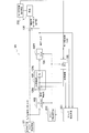
- FIG. 1 is a block diagram showing an example of the configuration of a driving force control apparatus for an electrically powered vehicle according to a first embodiment.
- FIG. 2 is a block diagram showing a configuration example of a driving force control device for an electric vehicle according to a comparison object.
- FIG. 3 is a schematic diagram for explaining the torsional vibration generated in the drive system.
- FIG. 4 is a block diagram showing a configuration example of a driving force control device for an electrically powered vehicle according to a second embodiment.
- FIG. 5 is a flowchart showing the processing procedure of the slip suppression process executed by the driving force control apparatus for the electrically powered vehicle according to the embodiment.
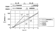
- FIG. 6 is a graph showing simulation results at the time of start regarding the motor rotational speed.
- FIG. 7 is a graph showing a simulation result at the start regarding the acceleration deviation.
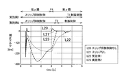
- FIG. 8 is a graph showing a simulation result at the start regarding the correction torque.
- FIG. 9 is a graph showing simulation results during traveling regarding the motor rotational speed.
- FIG. 10 is a graph showing simulation results during traveling regarding acceleration deviation.
- FIG. 11 is a graph showing simulation results during traveling regarding the correction torque.
- FIG. 12 is a block diagram showing a configuration example of a driving force control device for an electrically powered vehicle according to a third embodiment.
- FIG. 13 is a block diagram showing a configuration example of a driving force control device for an electrically powered vehicle according to the fourth embodiment.
- FIG. 14 is a flowchart showing the procedure of the slip suppression process executed by the drive force control apparatus for an electrically powered vehicle according to the fourth embodiment.
- FIG. 15 is a block diagram showing a configuration example of a driving force control device for an electrically powered vehicle according to another embodiment of the present invention.
- FIG. 16 is a block diagram showing a configuration example of a driving force control device for an electrically powered vehicle according to another embodiment of the present invention.
- FIG. 17 is a block diagram showing a configuration example of a driving force control device for an electrically powered vehicle according to the prior art.
- FIG. 2 Prior to the description of the driving force control device 1A of the electric vehicle according to the first embodiment, FIG. 2 and a configuration example of the driving force control device 300 of the electric vehicle according to the comparison object which is the basis of the present invention This will be described with reference to FIG.
- FIG. 2 is a block diagram showing a configuration example of the driving force control device 300 of the electric vehicle according to the comparison object.
- FIG. 3 is a schematic view for explaining the torsional vibration generated in the drive system 30. As shown in FIG.
- the driving force control device 300 of the electric vehicle according to the comparison object is mounted on a vehicle V such as an electric car.
- the driving force control device 300 of the electric vehicle according to the comparison object is a device that performs damping control of the vehicle V and the like.
- the driving force control device 300 of the electric vehicle calculates a target motor torque based on the driver's accelerator pedal operation, and a target motor torque calculating unit 301;
- Target acceleration computing means 302 for computing a target acceleration by dividing the velocity by inertia of the drive system, and motor rotational speed detecting means 250 for detecting an actual motor rotational speed (for example, a motor rotational speed detecting sensor etc.
- a correction amount calculation means 320 for calculating a correction amount for the motor torque command value so that the deviation between the target acceleration and the real acceleration becomes small;
- each means of the driving force control device 300 of the electric vehicle can be configured by a central processing unit (CPU), a memory, an arithmetic circuit, and the like.
- the vehicle V includes a drive system 30 as shown in FIG.
- the drive system 30 includes a motor 31 as a drive source, and wheels 34 connected to the motor 31 via an output shaft 32, a reduction gear 35 and a drive shaft 33.
- the rotation of the motor 31 is controlled by the motor torque command value TM finally applied to the control, which is calculated by the motor torque command value calculating means 306 shown in FIG.
- vibration In the drive system 30 of the vehicle V, when the motor 31 is rotated, vibration (twist vibration) occurs due to the twisting of the drive shaft 33.
- Target motor torque calculation means 301 shown in FIG. 2 calculates target motor torque Tm * based on the driver's accelerator pedal operation.
- the target motor torque Tm * is sent to the control motor torque command value calculation means 306 and the target acceleration calculation means 302.
- the target acceleration computing means 302 divides the target motor torque Tm * by the inertia of the drive system to calculate a target acceleration (ideal acceleration).
- the correction amount calculation means 320 has a deviation calculation means 320a and a proportional control means 320b.
- the correction amount calculation means 320 is connected to a modeling error suppression means 304 having a high pass filter HPF that constitutes a disturbance removal means.
- the deviation calculating means 320 a subtracts the actual acceleration calculated by differentiating the motor rotational speed ⁇ M detected by the motor rotational speed detecting means 250 by the actual acceleration calculating means 305 from the target acceleration calculated by the target acceleration calculating means 302. By doing this, the deviation between the target acceleration and the actual acceleration is calculated.
- the deviation between the target acceleration and the actual acceleration is input to the proportional control means 320b.
- the proportional control means 320b multiplies the deviation calculated by the deviation calculation means 320a by a predetermined proportional gain Kp to calculate a correction amount for suppressing the torsional vibration generated in the drive system 30.
- the value of the proportional gain Kp can be set as appropriate.
- the correction amount is to make the deviation between the target acceleration and the actual acceleration 0 or to be small, and this correction amount is input to the high pass filter HPF.
- the modeling error suppression means 304 suppresses the modeling error of the drive system 30 by causing the correction amount calculated by the correction amount calculation means 320 to pass through the high pass filter HPF.
- the motor torque command value calculation means 306 adds the correction amount (correction torque) obtained by removing the disturbance torque component by the high pass filter HPF to the target motor torque command value to obtain the final motor of the motor 31 for driving the vehicle V. Calculate torque command value TM [Nm].
- the motor 31 is rotated to generate a motor torque so as to match or follow the motor torque command value TM, and the motor torque is input to the drive system 30.
- the driving force control device 300 of the electric vehicle according to the comparison object can perform vibration control to suppress the torsional vibration.
- the driving force control apparatus 300 of the electric vehicle which concerns on comparison object was related to the technique which suppresses the "twisting vibration" which arises at the time of driving
- slip suppression control is to determine a torque command value which does not slip.
- the cutoff frequency ⁇ of the damping control when used, the correction torque for slip suppression does not pass through the high pass filter, and the slip is not suppressed. That is, when the cutoff frequency of damping control is selected, only the correction torque of the frequency for suppressing torsional vibration passes through the high-pass filter.
- the process of determining the final torque command value is performed by the motor controller. That is, since it is possible to finally determine the torque command value to be commanded to the motor by the motor controller, the process of the slip suppression control can be performed by the motor controller.
- FIG. 1 is a block diagram showing a configuration example of a driving force control device 1A of the electric vehicle according to the first embodiment.
- the driving force control device 1A of the electric powered vehicle controls the target motor torque Tm based on the accelerator operation of the driver for the electric powered vehicle (vehicle V) mounted with the motor 31 (see FIG. 3) as a driving source.
- the motor torque command is set so that the deviation between the target acceleration calculated by the target acceleration calculation means 102 and the actual acceleration calculated by the actual acceleration calculation means 105 becomes smaller.
- the correction amount calculation means 120 for calculating the correction amount (correction torque) for the vehicle and the correction amount calculated by the correction amount calculation means 120 are passed through the high pass filter HPF to set the drive system 30 between the ideal vehicle model and the actual vehicle.
- Modeling error suppression means 104 for suppressing an error
- control motor torque command value calculation means 106 for calculating a control motor torque command value to be finally applied to control by adding a correction amount to the motor torque command value
- Slip detection means 201 for detecting the presence or absence of slip based on the correction amount, the control motor torque command value, and the target motor torque, and the cutoff of the high pass filter HPF according to the detection result by the slip detection means 201
- Slip suppression control means cut-off frequency switching means for controlling to switch the frequency to suppress slip
- a 202 for controlling to switch the frequency to suppress slip
- the motor rotation number detection unit 250 is connected to the actual acceleration calculation unit 105, and inputs the motor rotation number to the actual acceleration calculation unit 105.
- Each means of the driving force control device 1A of the electric vehicle can be configured by a central processing unit (CPU), a memory, an arithmetic circuit, and the like.
- the slip suppression control means (cutoff frequency switching means) 202 generates the cut-off frequency of the high-pass filter HPF capable of suppressing the slip according to the detection result of the slip detection means 201, and generates the generated cut-off frequency.
- a plurality of cutoff frequencies may be stored in advance, and a cutoff frequency effective for suppressing slip may be selected therefrom.
- the main components of the driving force control device 1A of the electric vehicle according to the first embodiment and the driving force control device 300 of the electric vehicle according to the comparison object are provided with the slip detection means 201 and the slip suppression control means 202 which controls the slip to be suppressed according to the detection result of the slip detection means 201. is there.
- slip detection means 201 determines the conditions for either slip suppression control or torsional vibration damping control based on the correction amount, the control motor torque command value, and the target motor torque. Play a role as well.
- driving force control apparatus 1A of the electric vehicle has a configuration in which slip detection means 201 and slip suppression control means 202 are added to driving force control apparatus 300 of the electric vehicle according to the comparison object. It is also possible to perform damping control to suppress torsional vibration similar to that of the driving force control device 300 of the electric vehicle.
- driving force control apparatus 1A of the electric vehicle performs damping control to suppress torsional vibration, and slip detection means 201 detects the occurrence of slip.
- the control configuration can be switched to perform slip suppression control by the slip suppression control means 202.
- Target motor torque calculation means 101 shown in FIG. 1 calculates target motor torque Tm * based on the driver's accelerator pedal operation.
- the calculated target motor torque Tm * is sent to the control motor torque command value calculation means 106 and the target acceleration calculation means 102.
- the target acceleration computing means 102 divides the target motor torque Tm * by the inertia of the drive system 30 to calculate a target acceleration.
- the ideal vehicle model means a model assumed to be a complete rigid body without backlash in the vehicle drive system.
- the target acceleration computing means 102 computes the target acceleration of the motor of the ideal vehicle model by dividing the target motor torque Tm * by the inertia JT of the drive system.
- the transfer function Gm (s) of the ideal vehicle model can be represented, for example, by the following equation (1).
- Gm (s) ⁇ / ⁇ JT (s + ⁇ ) ⁇ (1)
- ⁇ [rad / s] is a cutoff frequency, and is set to the same value as ⁇ in Equations (2) and (3) described later.
- JT [Nms2] is the total inertia (inertia moment) converted to the motor axis, and s is the Laplace operator.
- the moment of inertia JT can be appropriately set according to the type of vehicle drive system.
- the correction amount calculation unit 120 includes a deviation calculation unit 120a and a proportional control unit 120b.
- the correction amount calculation means 120 is connected to a modeling error suppression means 104 having a high pass filter HPF that constitutes a disturbance removal means.
- the correction amount computing means 120 computes a correction amount for the motor torque command value based on the target acceleration computed by the target acceleration computing means 102 and the actual acceleration computed by the actual acceleration computing means 105.
- the correction amount is for suppressing the slip, and is calculated so that the deviation between the target acceleration and the actual acceleration is zero or smaller.
- the correction amount calculated by the correction amount calculation means 120 is input to the high pass filter HPF.
- the deviation calculating means 120 a is calculated by differentiating the motor rotational speed ⁇ M detected by the motor rotational speed detecting means 250 by the actual acceleration calculating means 105 from the target acceleration calculated by the target acceleration calculating means 102. By subtracting the acceleration, the deviation between the target acceleration and the actual acceleration is calculated.
- the motor rotational speed detecting means 250 calculates the motor rotational speed ⁇ M based on the signal received from the resolver (not shown).
- the high pass filter HPF performs dynamic correction processing (high pass filter processing) on the correction amount calculated by the proportional control unit 120 b to remove the disturbance torque component.
- the disturbance torque component that can be removed by the high-pass filter HPF is a traveling resistance torque component such as air resistance, a braking torque component due to a brake operation, and the like.
- the high pass filter HPF passes the high frequency side of the correction amount and blocks the low frequency side, removes the disturbance torque component included in the correction amount, and calculates the final correction amount.
- the high pass filter HPF can use a transfer function Gh (s) represented by the following equation (2).
- Gh (s) s / (s + ⁇ ) (2)
- s is a Laplace operator
- ⁇ [rad / s] is a cutoff frequency
- slip suppression can be achieved by setting the value of the constant ⁇ of the high pass filter HPF smaller than the constant ⁇ at the time of damping control.
- slip suppression control Such control is referred to as "slip suppression control" in the present embodiment.
- ⁇ 0.01 rad / s can be illustrated as the constant ⁇ at the time of slip suppression control.
- the constant ⁇ of the high pass filter HPF is set to a value smaller than the torsional vibration frequency.
- the constant ⁇ of the high pass filter HPF may be 10 rad / s or the like.
- the actual acceleration calculation means 105 differentiates the actual rotational speed ⁇ M [rad / s] of the motor 31 in the drive system 30 detected by the rotational speed detection means 250 to calculate an actual rotational acceleration (actual acceleration).
- the transfer characteristic (transfer function) Ga (s) of the actual acceleration calculation means 105 can be expressed, for example, by the following equation (3).
- Ga (s) s ⁇ / (s + ⁇ ) (3)
- ⁇ [rad / s] is the cutoff frequency of the high-pass filter HPF synthesized by equivalent conversion
- s is the Laplace operator.
- the actual acceleration is input to the correction amount calculation means 120.
- the part of ⁇ / (s + ⁇ ) included in the transfer function Ga (s) causes a delay similar to the part of ⁇ / (s + ⁇ ) included in the above-described transfer function Gm (s).
- the modeling error suppression means 104 suppresses the modeling error of the drive system 30 by causing the correction amount calculated by the correction amount calculation means 120 to pass through the high pass filter HPF (high pass filter processing).
- the control motor torque command value calculation means 106 adds the correction amount (correction torque) from which the disturbance torque component has been removed by the high pass filter HPF to the target motor torque command value so that the final result of the motor 31 driving the vehicle V is obtained.
- the control motor torque command value TM [Nm] is calculated.
- the motor 31 is rotated to generate a motor torque so as to match or follow the motor torque command value TM, and the motor torque is input to the drive system 30.
- the slip suppression control means 202 can control to start the slip suppression control when the motor rotational speed is less than the first predetermined value ⁇ 0 at the start of traveling of the vehicle V.
- the slip suppression control means 202 controls the motor rotation number to be a first predetermined value ⁇ 0 or more, the acceleration deviation to be less than a first predetermined value ae1, and the absolute value of the correction torque to be a second predetermined value while the vehicle V is traveling.
- the slip suppression control may be started when the three conditions of less than T2 are satisfied.
- the slip suppression control unit 202 terminates the slip suppression control when the motor rotational speed exceeds the second predetermined value ⁇ 1 and the absolute value of the correction torque is less than the first predetermined value T1. It may be controlled to
- the slip suppression control means 202 is configured such that while the vehicle V is traveling, the motor rotational speed is equal to or greater than the first predetermined value ⁇ 0, the absolute value of the acceleration deviation is less than the second predetermined value ae2, and the absolute value of the correction torque is the first
- the slip suppression control may be controlled to end when the three conditions of less than the predetermined value T1 of are satisfied.
- the slip suppression control can be ended at an appropriate timing.
- driving force control device for an electric vehicle according to the second embodiment A configuration example of the driving force control device 1B of the electric vehicle according to the second embodiment will be described with reference to FIG. 4 and FIG. 3 described above.
- FIG. 4 is a block diagram showing a configuration example of the driving force control device 1B of the electric vehicle according to the second embodiment.
- the main difference between the driving force control device 1B of the electric vehicle according to the second embodiment and the driving force control device 1A of the electric vehicle according to the first embodiment is that the correction amount calculation means 120 PI control means 260 for performing control in PI correction processing (proportional / integral control) in calculation processing of correction amount is provided, and control configuration switching means 270 for switching between vibration damping control of torsional vibration and suppression control of slip is provided. It is a point provided.
- Each means of the driving force control device 1B of the electric vehicle can be configured by a central processing unit (CPU), a memory, an arithmetic circuit, and the like.
- control configuration switching means 270 When the control configuration switching means 270 performs slip suppression control, it switches the control configuration to slip suppression control based on the input from the signal line 151 and performs torsional vibration damping control. The control configuration is switched for torsional vibration damping control based on the input from the signal line 150.
- slip suppression control means 202 performs, for example, correction amount calculation means when performing slip suppression control instead of vibration suppression control for suppressing torsional vibration.
- control in the calculation processing of the correction amount can be controlled to be switched from P control (proportional control) to PI control (proportional / integral control) executed by the PI control means 260.
- control can be switched to the PI control unit 260 configured by another software or the like.
- slip detection means 201 determines the conditions for either slip suppression control or torsional vibration damping control based on the correction amount, the control motor torque command value, and the target motor torque. Play a role as well.
- the driving force control device 1B of the electric vehicle according to the second embodiment has the same configuration as the driving force control device 300 of the electric vehicle according to the comparison object, the driving force control device 1B of the electric vehicle is It is also possible to perform vibration control to suppress torsional vibration.
- the driving force control device 1B of the electric vehicle performs damping control to suppress torsional vibration, and the slip detection unit 201 detects the occurrence of slip. In such a case, it is possible to perform an operation of switching so as to perform the slip suppression control by the slip suppression control means 202.
- the target motor torque calculation means 101 calculates a target motor torque Tm * based on the accelerator pedal operation of the driver.
- the calculated target motor torque Tm * is sent to the control motor torque command value calculation means 106, the target acceleration calculation means 102, and the slip detection means 201.
- the slip detection unit 201 detects the presence or absence of a slip based on the acceleration deviation amount, the correction torque, and the motor rotation number.
- the slip suppression control unit 202 executes the slip suppression control.
- the target acceleration calculation means 102 divides the target motor torque Tm * by the inertia of the drive system 30 to calculate a target acceleration (ideal acceleration).
- the target acceleration computing means 102 computes the target acceleration of the motor of the ideal vehicle model by dividing the target motor torque Tm * by the inertia JT of the drive system.
- the transfer function Gm (s) of the ideal vehicle model is the same as the equation (1) shown in the description of the driving force control device 1A of the electric vehicle according to the first embodiment.
- the actual acceleration calculation means 105 differentiates the actual rotational speed ⁇ M [rad / s] of the motor 31 in the drive system 30 detected by the rotational speed detection means 250 to calculate an actual rotational acceleration (actual acceleration).
- the transfer characteristic (transfer function) Ga (s) of the actual acceleration calculation means 105 is the same as the equation (3) shown in the description of the driving force control device 1A of the electric vehicle.
- the actual acceleration is input to the correction amount calculation means 120.
- the part of ⁇ / (s + ⁇ ) included in the transfer function Ga (s) causes a delay similar to the part of ⁇ / (s + ⁇ ) included in the above-described transfer function Gm (s).
- the correction amount calculation unit 120 includes a deviation calculation unit 120a and a proportional control unit 120b.
- the correction amount calculation means 120 is connected to a modeling error suppression means 104 having a high pass filter HPF that constitutes a disturbance removal means.
- the correction amount computing means 120 computes a correction amount for the motor torque command value based on the target acceleration computed by the target acceleration computing means 102 and the actual acceleration computed by the actual acceleration computing means 105.
- the correction amount is for suppressing the slip, and is calculated so that the deviation between the target acceleration and the actual acceleration is zero or smaller.
- the correction amount calculated by the correction amount calculation means 120 is input to the high pass filter HPF.
- the deviation calculating means 120 a subtracts the actual acceleration calculated by differentiating the motor rotational speed ⁇ M detected by the motor rotational speed detecting means 250 by the actual acceleration calculating means 105 from the target acceleration calculated by the target acceleration calculating means 102. By doing this, the deviation between the target acceleration and the actual acceleration is calculated.
- the high pass filter HPF performs a dynamic correction process (filter process) on the correction amount calculated by the proportional control unit 120 b to remove the disturbance torque component.
- the high pass filter HPF passes the high frequency side of the correction amount and blocks the low frequency side, removes the disturbance torque component included in the correction amount, and calculates the final correction amount.
- a transfer function Gh (s) as represented by the equation (2) shown in the description of the driving force control device 1A of the electric vehicle can be used.
- slip suppression can be achieved by setting the value of the constant ⁇ of the high pass filter HPF smaller than the constant ⁇ at the time of damping control.
- ⁇ 0.01 rad / s can be illustrated as the constant ⁇ at the time of slip suppression control.
- the constant ⁇ of the high pass filter HPF is set to a value smaller than the torsional vibration frequency.
- the constant ⁇ of the high pass filter HPF may be 10 rad / s or the like.
- the calculation processing of the correction amount is appropriately switched from the proportional control means 120b to the PI control means 260.
- the deviation between the ideal acceleration and the actual acceleration can be made zero, and the slip amount can be reduced more effectively.
- the modeling error suppression means 104 suppresses the modeling error of the drive system 30 by causing the correction amount calculated by the correction amount calculation means 120 to pass through the high pass filter HPF.
- the control configuration switching unit 270 Based on the output results from the modeling error suppression unit 104, the PI control unit 260, and the slip detection unit 201, the control configuration switching unit 270 appropriately switches the vibration suppression control of the torsional vibration and the suppression control of the slip.
- the control motor torque command value calculation means 106 adds the correction amount (correction torque) from which the disturbance torque component has been removed by the high pass filter HPF to the target motor torque command value so that the final result of the motor 31 driving the vehicle V is obtained.
- the control motor torque command value TM [Nm] is calculated.
- the control motor torque command value TM is input to the drive system 30 as shown in FIG. 3 described above, and the motor 31 is rotated to generate motor torque so as to match or follow the motor torque command value TM.
- the ignition switch of the vehicle V is turned on, and the vehicle V is in a state where it can start moving.
- the slip suppression process is a process that switches to the slip suppression control when the vehicle V is stopped and when the slip is detected, and performs the vibration suppression control of torsional vibration otherwise.
- step S10 it is determined whether the vehicle V is stopping. Specifically, for example, it is determined whether or not the motor rotational speed is 0 or less than the first predetermined value ⁇ 0, and in the case of “No”, the process proceeds to step S18 and vibration damping control of torsional vibration is performed. Do.
- This damping control is continued until, for example, the vehicle V is stopped by waiting for a signal or the like, and torsional vibration generated while the vehicle V is traveling is suppressed.
- step S10 when it is determined as "Yes” in step S10, the process proceeds to step S11, and slip suppression control is performed.
- step S12 it is determined whether the vehicle V has started traveling.
- step S11 it is determined whether or not the motor rotational speed is equal to or greater than the first predetermined value ⁇ 0, and in the case of “No”, the process returns to step S11 to continue slip suppression control, and in the case of “Yes”. The process proceeds to step S13 to end the slip suppression control.
- the slip suppression control is ended when the motor rotational speed exceeds the second predetermined value ⁇ 1 and the absolute value of the correction torque is less than the first predetermined value T1. It may be controlled to
- step S14 it is determined whether a slip has been detected.
- the condition of the determination at this time can be made when the deviation of acceleration is equal to or less than the threshold (ae1) and the absolute value of the correction torque is equal to or less than the threshold (T1).
- the acceleration deviation is cut by the high pass filter HPF, it does not appear in the value of the correction torque. From these conditions, it can be determined that a slip has occurred.
- step S14 when it determines with "No” by step S14, it transfers to step S18 and performs damping control of a torsional vibration.
- step S14 the process proceeds to the step S15 to perform slip suppression control.
- step S16 it is determined whether the end condition of the slip suppression control is satisfied.
- the termination condition of the slip suppression control can be set when the absolute value of the deviation of acceleration is equal to or less than the threshold (ae2) and the absolute value of the correction torque is equal to or less than the threshold (T1).
- the correction torque has a large value because a correction amount for suppressing the slip is necessary.
- step S17 the slip suppression control is ended, and the process proceeds to step S18 to switch to the damping control.
- step S18 The process similar to steps S14 to S17 may be performed after step S18.
- FIG. 6 is a graph showing simulation results at the time of start regarding the motor rotational speed.
- FIG. 7 is a graph showing simulation results at the time of start regarding the acceleration deviation.
- FIG. 8 is a graph showing a simulation result at the start regarding the correction torque.
- Example 1 in which the slip suppression control (P control) is switched to the vibration suppression control of torsional vibration at timing T1 and the control of the torsional vibration from slip suppression control (PI control) at timing T2 Embodiment 2 in which vibration control was switched to was performed.
- line L1 shows the state without slip suppression control
- line L2 shows the state without slip
- line L3 shows the example 1
- line L4 shows the example 2.
- line L10 indicates a state without slip suppression control
- line L11 indicates a state without slip
- line L12 indicates Example 1
- line L13 indicates Example 2.
- line L20 indicates a state without slip suppression control
- line L21 indicates a state without slip
- line L22 indicates Example 1
- line L23 indicates Example 2.
- no slip is the result of simulation all on a high ⁇ road, and refers to the motor rotational speed when not slipping.
- Example 1 performed simulation by P control, it is different from the rotation speed without slip.
- Example 2 since PI control was changed and simulation was performed, compared with Example 1, it turns out that slip can be controlled more.
- FIG. 9 is a graph which shows the simulation result in running regarding motor rotation speed.
- FIG. 10 is a graph showing simulation results during traveling regarding acceleration deviation.
- FIG. 11 is a graph showing simulation results during traveling regarding the correction torque.
- the high ⁇ road (high friction road) is switched to the low ⁇ road (low friction road) at point P2, and the low ⁇ road to the high ⁇ road is cut at point P3. It assumes a road surface to be replaced.
- Example 1 in which the vibration damping control of torsional vibration is switched to slip suppression control (P control) at timing T3 and is switched to vibration damping control of torsional vibration again at timing T4,
- the vibration damping control of the torsional vibration is switched to the slip suppression control (P control), and the vibration damping control of the torsional vibration is switched again at timing T6.
- the line L30 shows the state without slip suppression control
- the line L31 shows the state without slip
- the line L32 shows the example 1
- the line L33 shows the example 2.
- the line L40 shows the state without slip suppression control
- the line L41 shows the state without slip
- the line L42 shows the example 1
- the line L43 shows the example 2.
- a line L50 shows a state without slip suppression control
- a line L51 shows a state without slip
- a line L52 shows an example 1
- a line L53 shows an example 2.
- the slip can be further suppressed as compared with the first embodiment by changing to the PI control.
- driving force control device for an electric vehicle Next, the configuration of a driving force control device 1C for an electrically powered vehicle according to the third embodiment will be described with reference to FIG.
- the third embodiment is different from the first embodiment in that the driving force control device 1C includes a drive wheel rotation detection unit 280, a driven wheel rotation detection unit 290, and a slip ratio calculation unit 401.
- the slip detection unit 201 is calculated by the slip ratio calculation unit 401 instead of detecting the presence or absence of slip based on the acceleration deviation amount, the correction torque, and the motor rotational speed.
- the point is to detect the presence or absence of a slip based on a slip rate (hereinafter, also simply referred to as a slip rate).
- a slip rate hereinafter, also simply referred to as a slip rate
- the drive wheel rotation detection means 280 detects the rotation state of the drive wheel based on, for example, a signal of a wheel speed sensor of the drive wheel included in the vehicle V. More specifically, the drive wheel rotation detection means 280 detects the rotation speed of the drive wheel, and outputs the detected rotation speed of the drive wheel to the slip ratio calculation means 401.
- the driven wheel rotation detection means 290 detects the rotation state of the driven wheel based on, for example, a signal of a wheel speed sensor of the driven wheel included in the vehicle V. More specifically, the driven wheel rotation detection means 290 detects the rotational speed of the driven wheel, and outputs the detected rotational speed of the driven wheel to the slip ratio calculation means 401.
- the slip ratio calculation means 401 calculates the slip ratio based on the deviation between the rotational speed of the drive wheel and the rotational speed of the driven wheel.
- the slip ratio calculating unit 401 outputs the calculated slip ratio to the slip detecting unit 201.
- the slip detection unit 201 detects the presence or absence of a slip based on the slip ratio calculated by the slip ratio calculation unit 401. More specifically, the slip detection unit 201 determines that a slip has occurred when the slip ratio is equal to or less than a predetermined value.
- This predetermined value can be obtained in advance through simulation or experiment. For example, the predetermined value can be set to 0.2.
- the driving force control device 1A detects the presence or absence of a slip based on the acceleration deviation amount, the correction torque, and the motor rotation number.
- the correction torque is different from the actual torque because it is a torque based on the ideal vehicle model. Therefore, for example, when traveling downhill with a minicar carrying the number of passengers, an acceleration higher than that by the ideal vehicle model may occur. In such a case, the driving force control device 1A may erroneously detect that the vehicle V is slipping although the vehicle V is not slipping in practice.
- the driving force control device 1C detects the presence or absence of slip using the actual rotational speeds of the drive wheel and the driven wheel. Thereby, the driving force control device 1C can detect slip with high accuracy as compared with the driving force control device 1A.
- the slip ratio calculating unit 401 may be configured to have a function of detecting the presence or absence of a slip. Specifically, slip ratio calculation means 401 calculates the slip ratio, detects the presence or absence of slip based on the calculated slip ratio, and outputs the detection result to slip suppression control means 202 without passing through slip detection means 201. You may do it.
- the fourth embodiment is different from the first embodiment in that the driving force control device 1D includes a drive wheel rotation detection unit 280, a driven wheel rotation detection unit 290, and a slip ratio calculation unit 401.
- symbol is referred and the description is abbreviate
- the drive wheel rotation detection means 280, the driven wheel rotation detection means 290, and the slip ratio calculation means 401 are the same as in the third embodiment, the description thereof is also omitted.
- the slip detection by the slip detection unit 201 based on the acceleration deviation amount, the correction torque, and the motor rotation speed and the slip calculation by the slip ratio calculation unit 401 have the following characteristics. That is, in the slip detection by the slip detection means 201 based on the acceleration deviation amount, the correction torque, and the motor rotational speed, the responsiveness to the slip is excellent and the slip detection is also possible in the four-wheel drive vehicle.
- the slip detection unit 201 detects the presence or absence of slip twice. First, the slip detection means 201 detects the presence or absence of slip based on the acceleration deviation amount, the correction torque, and the motor rotational speed. Thereafter, the slip detection unit 201 detects the presence or absence of a slip based on the slip ratio calculated by the slip ratio calculation unit 401.
- the driving force control device 1D performs control according to the detection result of the first slip from when the presence or absence of the first slip is detected until when the presence or absence of the second slip is detected. Switch. Thereafter, the driving force control device 1D switches control in accordance with the second detection result of the slip.
- the slip suppression control unit 202 selects a cutoff frequency effective for the suppression of slip, and the slip suppression is performed. Take control. Thereafter, when the slip detection unit 201 detects a slip based on the slip ratio, that is, when the first and second detection results are the same, the slip suppression control unit 202 continues the slip suppression control. On the other hand, when the slip detection means 201 does not detect slip based on the slip ratio, that is, when the first and second detection results are different, the slip suppression control means 202 is a cutoff that is effective for suppressing torsional vibration. The frequency is reselected, and the driving force control device 1D performs damping control of torsional vibration.
- the slip suppression control means 202 selects a cutoff frequency effective for suppressing torsional vibration.
- the driving force control device 1D performs damping control of torsional vibration.
- the slip suppression control means 202 is a cutoff frequency effective for suppressing slip. Is selected and slip suppression control is performed.
- the driving force control device 1D continues the vibration control to suppress the torsional vibration. Do.
- step 41 damping control can be performed to suppress torsional vibration in the driving force control device 1D.
- step 42 for example, when the vehicle V is stopped by waiting for a signal or the like and then the vehicle V starts traveling, the slip detection means 201 performs slip based on the acceleration deviation amount, the correction torque, and the motor rotation number. To detect If the slip detection unit 201 detects a slip (Yes in step S42), the process proceeds to step S43. On the other hand, when the slip detection means 201 does not detect slip (No in step S42), the process proceeds to step S44.
- step S43 the slip suppression control unit 202 selects a cutoff frequency effective for suppressing slip, and performs slip suppression control.
- step S44 the slip detection unit 201 detects a slip based on the slip ratio. If the slip detection unit 201 detects a slip (Yes in step S44), the process returns to step S43. On the other hand, when the slip detection means 201 does not detect slip (No in step S44), the process proceeds to step S45.
- step S45 the driving force control device 1D performs vibration control to suppress torsional vibration.
- the driving force control device 1D uses the acceleration deviation amount, the correction torque, and the motor rotational speed to determine the presence or absence of the first slip in a method excellent in responsiveness. Control is performed based on the first detection result until detection and detection of the presence or absence of the second slip after that. Thereafter, the driving force control device 1D detects the presence or absence of the second slip, and performs control based on the second detection result in a highly accurate method. By thus detecting the slip twice with time intervals, the driving force control device 1D can correct the erroneous detection even when the first detection result is erroneous. In other words, by detecting the slip twice, the driving force control device 1D is able to achieve both responsiveness and accuracy.
- the slip ratio calculating unit 401 may be configured to have a function of detecting the presence or absence of a slip. Specifically, slip ratio calculation means 401 calculates the slip ratio, detects the presence or absence of slip based on the calculated slip ratio, and outputs the detection result to slip suppression control means 202 without passing through slip detection means 201. You may do it.
- the driving force control device 1B may be configured to include the driving wheel rotation detecting means 280, the driven wheel rotation detecting means 290, and the slip ratio calculating means 401 shown in FIG. Thereby, the driving force control device 1B can also detect the slip with high accuracy by detecting the slip twice.
- torsional vibration damping control and slip suppression control are performed based on motor acceleration, but instead, torsional vibration damping control is performed based on motor speed. Vibration control and slip suppression control may be performed.
- the driving force control device of the electric vehicle calculates target motor torque calculating means 101 for calculating the target motor torque based on the accelerator operation of the driver, for example, for the electric vehicle (vehicle V) equipped with the motor 31 as a driving source.
- Target speed calculation means for calculating the target speed based on the target motor torque
- the motor rotation number detection means 250 for detecting the actual motor rotation speed
- the motor rotation speed detected by the motor rotation number detection means 250 Based on the angular velocity computing means for computing the motor angular velocity, the correction amount for the motor torque command value so as to reduce the deviation between the target velocity computed by the target velocity computing means and the motor angular velocity computed by the angular velocity computing means.
- High-pass filter processing is performed on the correction amount calculation means to be calculated and the correction amount calculated by the correction amount calculation means Modeling error suppression means 104 for calculating torque, control motor torque command value calculation means 106 for calculating control motor torque command value by adding correction torque to motor torque command value, and at the time of start of vehicle, or
- the slip suppression control means 202 can be configured to control the cutoff frequency of the high pass filter HPF to be smaller at the time of slip detection so as to be smaller than that at the time of normal traveling to suppress the slip.
- the structure similar to 1 A of driving force control apparatuses of the electric vehicle which concerns on 1st Embodiment is applicable.
- motor rotational speed detecting means 250 for detecting the rotational speed of motor 31 and high pass filter HPF are provided to correct the motor torque command value.
- At least the amount calculating means 120 and the cutoff frequency switching means 202 for switching the cutoff frequency of the high pass filter HPF in accordance with the rotational speed of the motor detected by the motor rotational speed detecting means 250 may be provided.
- the cutoff frequency switching means 202 for switching the cutoff frequency of the high pass filter HPF is provided.
- the slip suppression control is performed after the slip is detected, but the slip suppression control may be uniformly performed when the vehicle starts (for example, the speed 0 to 10 km / h). .
- the target motor torque calculation means 101 may be configured by a vehicle controller 406.
- the vehicle controller 406 issues commands to a plurality of control devices based on signals from various sensors. This point is specifically described below.
- an accelerator sensor 402 detects an accelerator opening degree by an accelerator operation by a driver, and outputs the detected accelerator opening degree to a vehicle controller 406.
- the brake sensor 403 detects the amount of depression of the brake pedal by the driver and outputs the detected amount to the vehicle controller 406.
- the vehicle speed sensor detects the vehicle speed of the vehicle V and outputs the vehicle speed to the vehicle controller 406.
- the shift lever 405 detects shift information and outputs the shift information to the vehicle controller 406.
- the vehicle controller 406 receives signals from various sensors, and controls various functions (travel, stop, display, air conditioning, etc.) of the vehicle V. Specifically, the vehicle controller 406 outputs a torque command value to the motor controller 407 based on the accelerator opening. In addition, when the shift information is changed from P to another shift, the vehicle controller 406 outputs a signal to the parking actuator 409 to release the parking lock. In addition, the vehicle controller 406 displays the received vehicle speed on the meter 410. Further, the vehicle controller 406 outputs shift information and the like to the body controller 411. Communication between the vehicle controller 406 and the motor controller 407 is, for example, CAN.
- the motor controller 407 is, as shown in FIG. 16, a target acceleration calculating means 102, a motor rotational speed detecting means 250, an actual acceleration calculating means 105, a correction amount calculating means 120, a modeling error suppressing means 104, and a control motor torque command value.
- the calculation means 106 and the slip suppression control means 202 can be configured to be included.
- the motor controller 407 receives an instruction from the vehicle controller 406 and controls the inverter 408 to drive the motor 31.
- the vehicle controller 406 and the motor controller 407 can be configured by a central processing unit (CPU), a memory, an arithmetic circuit, and the like. Also in the configurations shown in FIGS. 4, 12 and 13, the configuration excluding the target motor torque calculation means 101 and the vehicle V is the motor controller 407.
- 1A, 1B driving force control device
- V vehicle (electric vehicle) Reference Signs List 30 drive system 31 motor 32 output shaft 33 drive shaft 34 wheel 35 reduction gear 101 target motor torque calculation means 102 target acceleration calculation means 104 modeling error suppression means 105 actual acceleration calculation means 106
- Motor torque command value calculation means for control 120 ... Correction amount calculation means 120a ... Deviation operation means 120b ... Proportional control means 201 ... Slip detection means (1st slip detection means) 202 ... Slip suppression control means (cutoff frequency switching means) 250 ... Motor rotational speed detection means 260 ... PI control means 270 ... Control configuration switching means 280 ... Drive wheel rotation detection means 290 ... Driven wheel rotation detection means 300 ... Drive force control device 301 ... Target motor torque calculation means 302 ...
- Target acceleration calculation Means 304 Modeling error suppression means 305: Actual acceleration calculation means 306: Control motor torque command value calculation means 320: Correction amount calculation means 320a: Deviation calculation means 320b: Proportional control means 401: Slip ratio calculation means (second slip Detection means) 402 ... accelerator sensor 403 ... brake sensor 404 ... vehicle speed sensor 405 ... shift lever 406 ... vehicle controller 407 ... motor controller 408 ... inverter 409 ... parking actuator 410 ... meter 411 ... body controller HPF ... high pass filter
Landscapes
- Engineering & Computer Science (AREA)
- Power Engineering (AREA)
- Transportation (AREA)
- Mechanical Engineering (AREA)
- Life Sciences & Earth Sciences (AREA)
- Sustainable Development (AREA)
- Sustainable Energy (AREA)
- Electric Propulsion And Braking For Vehicles (AREA)
- Control Of Electric Motors In General (AREA)
Abstract
Description
(比較対象について)
第1の実施の形態に係る電動車両の駆動力制御装置1Aについての説明に先立って、本発明の元となった比較対象に係る電動車両の駆動力制御装置300の構成例について、図2および図3を参照して説明する。
第1の実施の形態に係る電動車両の駆動力制御装置1Aの構成例について、図1および前出の図3を参照して説明する。
まず、スリップを抑制するためには、スリップしないようなモータトルクにする必要がある。即ち、「スリップ抑制制御」とは、スリップしないようなトルク指令値を決めることであるといえる。
ここで、ω[rad/s]は、カットオフ周波数であり、後述の式(2)、(3)のωと同じ値に設定される。
式(2)において、sはラプラス演算子であり、ω[rad/s]はカットオフ周波数である。
スリップ抑制制御時の定数ωとしては、例えばω=0.01rad/sを例示することができる。
ここで、ω[rad/s]は等価変換で合成したハイパスフィルタHPFのカットオフ周波数であり、sはラプラス演算子である。
第2の実施の形態に係る電動車両の駆動力制御装置1Bの構成例について、図4および前出の図3を参照して説明する。
図5のフローチャートを参照して、上述の第1の実施の形態に係る電動車両の駆動力制御装置1Aおよび第2の実施の形態に係る電動車両の駆動力制御装置1Bで実行されるスリップ抑制処理の処理手順について説明する。
図6から図11のグラフを参照して、本実施の形態に係る電動車両の駆動力制御装置1A、1Bのシミュレーション結果について説明する。
次に、図12を参照して第3の実施の形態に係る電動車両の駆動力制御装置1Cの構成について説明する。
次に、図13を参照して第4の実施の形態に係る電動車両の駆動力制御装置1Dの構成について説明する。
V…車両(電動車両)
30…駆動系
31…モータ
32…出力軸
33…駆動軸
34…車輪
35…減速機
101…目標モータトルク算出手段
102…目標加速度演算手段
104…モデル化誤差抑制手段
105…実加速度演算手段
106…制御用モータトルク指令値算出手段
120…補正量演算手段
120a…偏差演算手段
120b…比例制御手段
201…スリップ検出手段(第1スリップ検出手段)
202…スリップ抑制制御手段(カットオフ周波数切換手段)
250…モータ回転数検出手段
260…PI制御手段
270…制御構成切換手段
280…駆動輪回転検出手段
290…従動輪回転検出手段
300…駆動力制御装置
301…目標モータトルク算出手段
302…目標加速度演算手段
304…モデル化誤差抑制手段
305…実加速度演算手段
306…制御用モータトルク指令値算出手段
320…補正量演算手段
320a…偏差演算手段
320b…比例制御手段
401…スリップ率算出手段(第2スリップ検出手段)
402…アクセルセンサ
403…ブレーキセンサ
404…車速センサ
405…シフトレバー
406…車両コントローラ
407…モータコントローラ
408…インバータ
409…パーキングアクチュエータ
410…メータ
411…ボディコントローラ
HPF…ハイパスフィルタ
Claims (14)
- モータ(31)を駆動源として搭載する電動車両(車両V)について、運転者のアクセル操作に基づいて目標モータトルクを算出する目標モータトルク算出手段(101)と、
前記目標モータトルクを前記電動車両が搭載する駆動系の慣性で除算して、目標加速度を演算する目標加速度演算手段(102)と、
実際のモータ回転数を検出するモータ回転数検出手段(250)と、
前記モータ回転数検出手段で検出されたモータ回転数を微分して実加速度を演算する実加速度演算手段(105)と、
前記目標加速度演算手段で算出された目標加速度と、前記実加速度演算手段で算出された実加速度との偏差が小さくなるように、モータトルク指令値に対する補正量を演算する補正量演算手段(120)と、
前記補正量演算手段によって算出される補正量に対してハイパスフィルタ処理を行って、補正トルクを演算するモデル化誤差抑制手段(104)と、
前記モータトルク指令値に前記補正トルクを加算して、制御用モータトルク指令値を算出する制御用モータトルク指令値算出手段(106)と、
車両の発進時、又は、スリップ検出時に、ハイパスフィルタ(HPF)のカットオフ周波数を、通常走行時と比較して小さくなるよう切り換えてスリップを抑制するように制御するスリップ抑制制御手段(202)と、
を備えることを特徴とする電動車両の駆動力制御装置。 - 前記補正量と、前記補正トルクと、前記モータ回転数とに基づいて、スリップの有無を検出する第1スリップ検出手段(201)をさらに備えることを特徴とする請求項1に記載の電動車両の駆動力制御装置。
- 前記スリップ抑制制御手段は、
スリップの抑制制御を行う際に、前記補正量演算手段による前記補正量の演算処理の制御をP制御(比例制御)からPI制御(比例・積分制御)に切り換えるように制御することを特徴とする請求項1または請求項2に記載の電動車両の駆動力制御装置。 - 前記スリップ抑制制御手段は、
前記電動車両の走行開始時に、前記モータ回転数が第1の所定値ω0未満である場合に、スリップの抑制制御を開始するように制御することを特徴とする請求項1から請求項3の何れか1項に記載の電動車両の駆動力制御装置。 - 前記スリップ抑制制御手段は、
前記電動車両の走行中に、前記モータ回転数が第1の所定値ω0以上、加速度偏差が第1の所定値ae1以下、補正トルクの絶対値が第1の所定値T1以下という3条件を満たした場合にスリップの抑制制御を開始するように制御することを特徴とする請求項1から請求項4の何れか1項に記載の電動車両の駆動力制御装置。 - 前記スリップ抑制制御手段は、
前記モータ回転数が第2の所定値ω1を超え、且つ、補正トルクの絶対値が第1の所定値T1未満である場合に、スリップの抑制制御を終了するように制御することを特徴とする請求項1から請求項5の何れか1項に記載の電動車両の駆動力制御装置。 - 前記スリップ抑制制御手段は、
前記電動車両の走行中に、モータ回転数が第1の所定値ω0以上、加速度偏差の絶対値が第2の所定値ae2以下、補正トルクの絶対値が第2の所定値T2以下という3条件を満たした場合にスリップの抑制制御を終了するように制御することを特徴とする請求項1から請求項6の何れか1項に記載の電動車両の駆動力制御装置。 - モータ(31)を駆動源として搭載する電動車両(車両V)について、前記モータの回転数を検出するモータ回転数検出手段(250)と、
ハイパスフィルタ(HPF)を備え、モータトルク指令値に対する補正量を演算する補正量演算手段(120)と、
前記モータ回転数検出手段で検出されたモータの回転数に応じて、前記ハイパスフィルタのカットオフ周波数を切り換えるカットオフ周波数切換手段(202)と、
を少なくとも備えることを特徴とする電動車両の駆動力制御装置。 - モータ(31)を駆動源として搭載する電動車両(車両V)について、運転者のアクセル操作に基づいて目標モータトルクを算出する目標モータトルク算出手段(101)と、
前記目標モータトルクに基づいて、目標速度を演算する目標速度演算手段と、
実際のモータ回転数を検出するモータ回転数検出手段(250)と、
前記モータ回転数検出手段で検出されたモータ回転数に基づいてモータ角速度を演算する角速度演算手段と、
前記目標速度演算手段で算出された目標速度と、前記角速度演算手段で算出されたモータ角速度との偏差が小さくなるように、モータトルク指令値に対する補正量を演算する補正量演算手段と、
前記補正量演算手段によって算出される補正量に対してハイパスフィルタ処理を行って、補正トルクを演算するモデル化誤差抑制手段(104)と、
前記モータトルク指令値に前記補正トルクを加算して、制御用モータトルク指令値を算出する制御用モータトルク指令値算出手段(106)と、
車両の発進時、又は、スリップ検出時に、ハイパスフィルタ(HPF)のカットオフ周波数を、通常走行時と比較して小さくなるよう切り換えてスリップを抑制するように制御するスリップ抑制制御手段(202)と、
を備えることを特徴とする電動車両の駆動力制御装置。 - 電動車両の駆動輪の回転状態を検出する駆動輪回転検出手段(280)と、
電動車両の従動輪の回転状態を検出する従動輪回転検出手段(290)と、
前記駆動輪回転検出手段(280)によって検出された前記駆動輪の回転状態と、前記従動輪回転検出手段(290)によって検出された前記従動輪の回転状態との偏差からスリップの有無を検出する第2スリップ検出手段(401)とをさらに備えることを特徴とする請求項1に記載の電動車両の駆動力制御装置。 - 電動車両の駆動輪の回転状態を検出する駆動輪回転検出手段(280)と、
電動車両の従動輪の回転状態を検出する従動輪回転検出手段(290)と、
前記駆動輪回転検出手段(280)によって検出された前記駆動輪の回転状態と、前記従動輪回転検出手段(290)によって検出された前記従動輪の回転状態との偏差からスリップの有無を検出する第2スリップ検出手段(401)と、をさらに備え
前記第2スリップ検出手段(401)は、前記第1スリップ検出手段(201)によってスリップが検出された後に、スリップの有無を検出することを特徴とする請求項2に記載の電動車両の駆動力制御装置。 - スリップ抑制制御手段(202)は、前記第1スリップ検出手段(201)によってスリップが検出された場合、前記第2スリップ検出手段(401)によってスリップの有無が検出されるまでの間は、ハイパスフィルタ(HPF)のカットオフ周波数を、通常走行時と比較して小さくなるよう切り換えてスリップを抑制することを特徴とする請求項11に記載の電動車両の駆動力制御装置。
- 前記第1スリップ検出手段(201)によるスリップの検出結果と、前記第2スリップ検出手段(401)によるスリップの検出結果が相違する場合、前記スリップ抑制制御手段(202)は、前記第2スリップ検出手段(401)によるスリップの検出結果に基づいて、カットオフ周波数を再選択することを特徴とする請求項12に記載の電動車両の駆動力制御装置。
- 前記目標モータトルク算出手段(101)は、複数の制御装置に対して指令を行う車両コントローラ(406)であり、
前記目標加速度演算手段(102)、前記モータ回転数検出手段(250)、前記実加速度演算手段(105)、前記補正量演算手段(120)、前記モデル化誤差抑制手段(104)、前記制御用モータトルク指令値算出手段(106)及び前記スリップ抑制制御手段(202)は、前記車両コントローラ(406)から指令を受けて前記モータ(31)を駆動させるモータコントローラ(407)であることを特徴とする請求項1~7、10~13の何れか1項に記載の電動車両の駆動力制御装置。
Priority Applications (4)
| Application Number | Priority Date | Filing Date | Title |
|---|---|---|---|
| DE112016001432.5T DE112016001432T5 (de) | 2015-03-27 | 2016-03-25 | Antriebsleistungssteuerungsvorrichtung für elektrofahrzeug |
| JP2017509891A JP6389955B2 (ja) | 2015-03-27 | 2016-03-25 | 電動車両の駆動力制御装置 |
| US15/560,627 US10391884B2 (en) | 2015-03-27 | 2016-03-25 | Drive power control device for electric vehicle |
| CN201680019088.9A CN107428260B (zh) | 2015-03-27 | 2016-03-25 | 电动车辆的驱动力控制装置 |
Applications Claiming Priority (2)
| Application Number | Priority Date | Filing Date | Title |
|---|---|---|---|
| JP2015-066286 | 2015-03-27 | ||
| JP2015066286 | 2015-03-27 |
Publications (1)
| Publication Number | Publication Date |
|---|---|
| WO2016158720A1 true WO2016158720A1 (ja) | 2016-10-06 |
Family
ID=57004305
Family Applications (1)
| Application Number | Title | Priority Date | Filing Date |
|---|---|---|---|
| PCT/JP2016/059552 Ceased WO2016158720A1 (ja) | 2015-03-27 | 2016-03-25 | 電動車両の駆動力制御装置 |
Country Status (5)
| Country | Link |
|---|---|
| US (1) | US10391884B2 (ja) |
| JP (1) | JP6389955B2 (ja) |
| CN (1) | CN107428260B (ja) |
| DE (1) | DE112016001432T5 (ja) |
| WO (1) | WO2016158720A1 (ja) |
Cited By (11)
| Publication number | Priority date | Publication date | Assignee | Title |
|---|---|---|---|---|
| CN106740267A (zh) * | 2017-01-25 | 2017-05-31 | 北京新能源汽车股份有限公司 | 一种输出扭矩的控制方法及系统 |
| CN107399250A (zh) * | 2017-07-12 | 2017-11-28 | 深圳市大地和电气股份有限公司 | 消除新能源电动汽车抖动的方法及系统 |
| CN108016319A (zh) * | 2016-10-31 | 2018-05-11 | 大陆汽车投资(上海)有限公司 | 用于管理电动车辆中的电机的转矩的装置和方法 |
| JP2018184038A (ja) * | 2017-04-24 | 2018-11-22 | 本田技研工業株式会社 | 倒立振子型車両 |
| JP2021168564A (ja) * | 2020-04-10 | 2021-10-21 | 株式会社デンソー | 制御装置 |
| JP2021168563A (ja) * | 2020-04-10 | 2021-10-21 | 株式会社デンソー | 制御装置 |
| JP2023025753A (ja) * | 2021-08-11 | 2023-02-24 | 東京電力ホールディングス株式会社 | 運搬車両制御装置、運搬車両及びプログラム |
| JP2023144497A (ja) * | 2022-03-28 | 2023-10-11 | 株式会社デンソー | モータ制御装置およびプログラム |
| KR20240085505A (ko) * | 2022-12-08 | 2024-06-17 | 한국철도기술연구원 | 자율주행 트램의 상태추정 방법 및 이를 이용한 시스템 |
| JP2024113287A (ja) * | 2023-02-09 | 2024-08-22 | トヨタ自動車株式会社 | 電動車両の制御装置 |
| US12224685B2 (en) | 2020-06-01 | 2025-02-11 | Hitachi Astemo, Ltd. | Motor control device and motor controlling method |
Families Citing this family (25)
| Publication number | Priority date | Publication date | Assignee | Title |
|---|---|---|---|---|
| US10333448B2 (en) * | 2017-04-10 | 2019-06-25 | GM Global Technology Operations LLC | Method for torque control systems and methods based on rotor temperature |
| GB2571331B (en) | 2018-02-26 | 2021-06-23 | Jaguar Land Rover Ltd | BEV torque split control |
| CN109131341B (zh) * | 2018-07-09 | 2022-04-12 | 中国北方车辆研究所 | 一种用于全轮独立驱动车辆的驱动轮滑动检测方法及系统 |
| CN109017449B (zh) * | 2018-08-17 | 2021-05-07 | 南京越博动力系统股份有限公司 | 一种纯电动车的驱动防滑控制方法及系统 |
| US10875450B2 (en) * | 2018-09-06 | 2020-12-29 | Ford Global Technologies, Llc | Electrified vehicle and method for providing driver feedback by producing torque ripple |
| CN110171297A (zh) * | 2019-05-05 | 2019-08-27 | 北京新能源汽车股份有限公司 | 电动汽车的驱动电机输出扭矩控制方法、系统及车辆 |
| JP7349271B2 (ja) * | 2019-06-20 | 2023-09-22 | 株式会社日立製作所 | 列車保安システム、列車保安制御方法及び列車車上装置 |
| AT522353B1 (de) * | 2019-08-05 | 2020-10-15 | Avl List Gmbh | Prüfstand und Verfahren zur Durchführung eines Prüflaufs auf einem Prüfstand |
| CN114929535A (zh) * | 2019-10-21 | 2022-08-19 | 沃尔沃卡车集团 | 用于操作车辆的方法 |
| WO2021084574A1 (ja) * | 2019-10-28 | 2021-05-06 | 日産自動車株式会社 | 電動車両の制御方法及び電動車両の制御装置 |
| CN110696829B (zh) * | 2019-11-18 | 2021-04-09 | 安徽江淮汽车集团股份有限公司 | 处理车辆腾空打滑的方法、装置、电动汽车以存储介质 |
| JP7390220B2 (ja) * | 2020-03-13 | 2023-12-01 | 本田技研工業株式会社 | 駆動力制御装置 |
| KR20220014917A (ko) * | 2020-07-28 | 2022-02-08 | 현대자동차주식회사 | 차량의 선회 제어 시스템 및 제어 방법 |
| CN112009268B (zh) * | 2020-09-16 | 2021-10-22 | 北京车和家信息技术有限公司 | 一种车辆抖动控制方法及装置、驱动控制系统、车辆 |
| CN115214726B (zh) * | 2021-04-19 | 2025-05-13 | 比亚迪股份有限公司 | 车辆停车控制方法及装置 |
| CN113415173B (zh) * | 2021-06-04 | 2022-02-18 | 浙江零跑科技股份有限公司 | 基于lpf-hpf转速滤波的新能源汽车抑抖控制方法 |
| CN115723583B (zh) * | 2021-08-25 | 2025-06-27 | 陕西重型汽车有限公司 | 一种车用多轴分布式智能驱动控制方法 |
| CN117836168B (zh) * | 2021-08-30 | 2025-01-07 | 日产自动车株式会社 | 电动车辆的控制方法以及电动车辆的控制装置 |
| KR20230037177A (ko) * | 2021-09-09 | 2023-03-16 | 현대자동차주식회사 | 차량의 휠 슬립 제어 방법 |
| US12311773B2 (en) * | 2021-12-20 | 2025-05-27 | Dana Motion Systems Italia S.R.L. | Methods and systems for ensuring compliance of an electric vehicle |
| EP4431332A1 (en) * | 2023-03-14 | 2024-09-18 | Volvo Construction Equipment AB | Method for controlling an electric drive unit of a vehicle, computer program, computer readable medium, control unit, electric drive unit, and vehicle |
| CN116674394B (zh) * | 2023-05-24 | 2025-12-19 | 中科意创(广州)科技有限公司 | 一种扭矩估算方法、装置及汽车 |
| JP7770362B2 (ja) * | 2023-08-02 | 2025-11-14 | 本田技研工業株式会社 | 車両制御システム |
| CN118849809B (zh) * | 2024-09-24 | 2024-12-20 | 浙江极氪智能科技有限公司 | 一种电驱动系统主动控制方法、装置、车辆及存储介质 |
| CN121722168A (zh) * | 2026-02-27 | 2026-03-24 | 北京北特圣迪科技发展有限公司 | 一种基于关键节点动态映射的表演轨道船速度调优方法 |
Citations (5)
| Publication number | Priority date | Publication date | Assignee | Title |
|---|---|---|---|---|
| JPH07186665A (ja) * | 1993-12-24 | 1995-07-25 | Nissan Motor Co Ltd | サスペンション制御装置 |
| JP2000052964A (ja) * | 1998-08-07 | 2000-02-22 | Toyota Motor Corp | 車輌の加減速度演算方法 |
| JP2009095145A (ja) * | 2007-10-09 | 2009-04-30 | Denso Corp | 回転機の制御装置 |
| JP2013169054A (ja) * | 2012-02-15 | 2013-08-29 | Nissan Motor Co Ltd | 電動モータを用いた車両の制振制御装置 |
| WO2015111341A1 (ja) * | 2014-01-22 | 2015-07-30 | カルソニックカンセイ株式会社 | 電動車両の駆動力制御装置 |
Family Cites Families (29)
| Publication number | Priority date | Publication date | Assignee | Title |
|---|---|---|---|---|
| US5444351A (en) * | 1993-07-06 | 1995-08-22 | Nissan Motor Co., Ltd. | System and method for controlling induction motor applicable to electric motor-driven vehicle |
| JPH08182118A (ja) | 1994-12-22 | 1996-07-12 | Fuji Heavy Ind Ltd | 電気自動車の駆動制御装置 |
| JP3257351B2 (ja) * | 1995-07-07 | 2002-02-18 | 三菱自動車工業株式会社 | 車両の旋回制御装置 |
| US5633456A (en) * | 1995-08-04 | 1997-05-27 | Chrysler Corporation | Engine misfire detection with digital filtering |
| JP3526675B2 (ja) * | 1995-09-14 | 2004-05-17 | 日産ディーゼル工業株式会社 | 車輪の駆動トルク制御装置 |
| US5720533A (en) * | 1996-10-15 | 1998-02-24 | General Motors Corporation | Brake control system |
| JP4129702B2 (ja) * | 1997-07-11 | 2008-08-06 | マツダ株式会社 | 車両の姿勢制御装置 |
| US6035251A (en) * | 1997-11-10 | 2000-03-07 | General Motors Corporation | Brake system control method employing yaw rate and ship angle control |
| JP4194724B2 (ja) * | 1999-10-07 | 2008-12-10 | 株式会社豊田中央研究所 | 車両走行状態検出装置 |
| JP3775562B2 (ja) * | 2000-03-07 | 2006-05-17 | ジヤトコ株式会社 | パラレルハイブリッド車両 |
| EP1357007B1 (en) * | 2002-04-23 | 2006-05-17 | Aisin Seiki Kabushiki Kaisha | Wheel grip factor estimation apparatus |
| WO2003095261A1 (en) * | 2002-05-07 | 2003-11-20 | Kabushiki Kaisha Bridgestone | Method and device for controlling vehicle |
| JP4295962B2 (ja) * | 2002-07-29 | 2009-07-15 | アイシン精機株式会社 | 自動変速機の変速制御装置 |
| JP4213994B2 (ja) * | 2003-05-28 | 2009-01-28 | 株式会社豊田中央研究所 | タイヤグリップ度推定装置及び方法、走行状態制御方法 |
| US20050038589A1 (en) * | 2003-08-14 | 2005-02-17 | Deepak Shukla | Method for estimating a friction coefficient |
| US6856886B1 (en) * | 2004-03-23 | 2005-02-15 | General Motors Corporation | Vehicle stability enhancement control and method |
| US7274984B2 (en) * | 2004-06-14 | 2007-09-25 | General Motors Corporation | Vehicle stability enhancement system |
| JP4538642B2 (ja) * | 2006-09-07 | 2010-09-08 | 国立大学法人横浜国立大学 | スリップ率推定装置およびスリップ率制御装置 |
| JP4693790B2 (ja) * | 2007-01-09 | 2011-06-01 | ヤマハ発動機株式会社 | 自動二輪車、その制御装置および制御方法、並びに自動二輪車のスリップ量検出装置およびスリップ量検出方法 |
| JP5286921B2 (ja) * | 2008-05-12 | 2013-09-11 | 日産自動車株式会社 | 車両用制振制御装置 |
| US9145127B2 (en) * | 2008-12-26 | 2015-09-29 | Komatsu Ltd. | Traction control device |
| EP2374673B1 (en) * | 2008-12-26 | 2013-08-21 | Komatsu Ltd. | Traction control device |
| JP2012076537A (ja) * | 2010-09-30 | 2012-04-19 | Aisin Aw Co Ltd | 制御装置 |
| US8631693B2 (en) * | 2010-12-23 | 2014-01-21 | Horiba Instruments, Inc. | Wheel slip simulation systems and methods |
| US8706378B2 (en) * | 2011-11-28 | 2014-04-22 | Toyota Motor Engineering & Manufacturing North America, Inc. | Systems and methods for determining road mu and drive force |
| JP5824406B2 (ja) * | 2012-04-20 | 2015-11-25 | 日立建機株式会社 | 電気駆動車両 |
| US9457787B2 (en) * | 2012-05-07 | 2016-10-04 | Ford Global Technologies, Llc | Method and system to manage driveline oscillations with motor torque adjustment |
| EP2899086A4 (en) * | 2012-09-20 | 2016-06-01 | Pioneer Corp | DEVICE FOR ESTIMATING THE SLIP RATIO AND METHOD FOR ESTIMATING THE SLIP RATIO |
| TW201710924A (zh) * | 2015-09-14 | 2017-03-16 | 義守大學 | 以多項式估測感應機參數之方法 |
-
2016
- 2016-03-25 WO PCT/JP2016/059552 patent/WO2016158720A1/ja not_active Ceased
- 2016-03-25 CN CN201680019088.9A patent/CN107428260B/zh not_active Expired - Fee Related
- 2016-03-25 JP JP2017509891A patent/JP6389955B2/ja active Active
- 2016-03-25 DE DE112016001432.5T patent/DE112016001432T5/de not_active Ceased
- 2016-03-25 US US15/560,627 patent/US10391884B2/en active Active
Patent Citations (5)
| Publication number | Priority date | Publication date | Assignee | Title |
|---|---|---|---|---|
| JPH07186665A (ja) * | 1993-12-24 | 1995-07-25 | Nissan Motor Co Ltd | サスペンション制御装置 |
| JP2000052964A (ja) * | 1998-08-07 | 2000-02-22 | Toyota Motor Corp | 車輌の加減速度演算方法 |
| JP2009095145A (ja) * | 2007-10-09 | 2009-04-30 | Denso Corp | 回転機の制御装置 |
| JP2013169054A (ja) * | 2012-02-15 | 2013-08-29 | Nissan Motor Co Ltd | 電動モータを用いた車両の制振制御装置 |
| WO2015111341A1 (ja) * | 2014-01-22 | 2015-07-30 | カルソニックカンセイ株式会社 | 電動車両の駆動力制御装置 |
Cited By (16)
| Publication number | Priority date | Publication date | Assignee | Title |
|---|---|---|---|---|
| CN108016319A (zh) * | 2016-10-31 | 2018-05-11 | 大陆汽车投资(上海)有限公司 | 用于管理电动车辆中的电机的转矩的装置和方法 |
| CN106740267A (zh) * | 2017-01-25 | 2017-05-31 | 北京新能源汽车股份有限公司 | 一种输出扭矩的控制方法及系统 |
| JP2018184038A (ja) * | 2017-04-24 | 2018-11-22 | 本田技研工業株式会社 | 倒立振子型車両 |
| CN107399250A (zh) * | 2017-07-12 | 2017-11-28 | 深圳市大地和电气股份有限公司 | 消除新能源电动汽车抖动的方法及系统 |
| JP7447651B2 (ja) | 2020-04-10 | 2024-03-12 | 株式会社デンソー | 制御装置 |
| JP2021168563A (ja) * | 2020-04-10 | 2021-10-21 | 株式会社デンソー | 制御装置 |
| JP2021168564A (ja) * | 2020-04-10 | 2021-10-21 | 株式会社デンソー | 制御装置 |
| JP7447650B2 (ja) | 2020-04-10 | 2024-03-12 | 株式会社デンソー | 制御装置 |
| US12224685B2 (en) | 2020-06-01 | 2025-02-11 | Hitachi Astemo, Ltd. | Motor control device and motor controlling method |
| JP2023025753A (ja) * | 2021-08-11 | 2023-02-24 | 東京電力ホールディングス株式会社 | 運搬車両制御装置、運搬車両及びプログラム |
| JP7664790B2 (ja) | 2021-08-11 | 2025-04-18 | 東京電力ホールディングス株式会社 | 運搬車両制御装置、運搬車両及びプログラム |
| JP2023144497A (ja) * | 2022-03-28 | 2023-10-11 | 株式会社デンソー | モータ制御装置およびプログラム |
| KR20240085505A (ko) * | 2022-12-08 | 2024-06-17 | 한국철도기술연구원 | 자율주행 트램의 상태추정 방법 및 이를 이용한 시스템 |
| KR102831162B1 (ko) | 2022-12-08 | 2025-07-09 | 한국철도기술연구원 | 자율주행 트램의 상태추정 방법 및 이를 이용한 시스템 |
| JP2024113287A (ja) * | 2023-02-09 | 2024-08-22 | トヨタ自動車株式会社 | 電動車両の制御装置 |
| JP7826968B2 (ja) | 2023-02-09 | 2026-03-10 | トヨタ自動車株式会社 | 電動車両の制御装置 |
Also Published As
| Publication number | Publication date |
|---|---|
| US10391884B2 (en) | 2019-08-27 |
| US20180056811A1 (en) | 2018-03-01 |
| DE112016001432T5 (de) | 2017-12-14 |
| JPWO2016158720A1 (ja) | 2018-01-18 |
| CN107428260B (zh) | 2020-03-10 |
| JP6389955B2 (ja) | 2018-09-12 |
| CN107428260A (zh) | 2017-12-01 |
Similar Documents
| Publication | Publication Date | Title |
|---|---|---|
| JP6389955B2 (ja) | 電動車両の駆動力制御装置 | |
| CN108136933B (zh) | 电动车辆的控制装置、电动车辆的控制系统及电动车辆的控制方法 | |
| JP6519871B2 (ja) | 電動車両の制御装置、電動車両の制御システム及び電動車両の制御方法 | |
| JP5945572B2 (ja) | 駆動力制御システムおよび鞍乗り型車両 | |
| US9376112B2 (en) | Vehicle control device and vehicle control method | |
| JP6380309B2 (ja) | 車両の制御装置 | |
| US20180186406A1 (en) | Power steering apparatus control device and power steering apparatus | |
| JP6578584B2 (ja) | 電動車両の制御装置 | |
| JP5808977B2 (ja) | 車両のヨーモーメント発生旋回効率化装置 | |
| JP2021002328A (ja) | 自動二輪車の運転者に警告するための方法、ならびにそのような方法を実行するための運転補助制御装置及び自動二輪車 | |
| WO2018230341A1 (ja) | 車両制御装置 | |
| CN118613384A (zh) | 移动体的控制系统、程序 | |
| JP2017158261A (ja) | 車両の制御装置及び車両の制御方法 | |
| KR101976276B1 (ko) | 전자식 lsd의 제어장치 및 그 제어방법 | |
| JP6408408B2 (ja) | 電動車両の駆動力制御装置 | |
| WO2021245974A1 (ja) | モータ制御装置およびモータ制御方法 | |
| JPH0439790Y2 (ja) | ||
| JP2012180011A (ja) | 車両の姿勢制御装置 | |
| JP2005125894A (ja) | 車両の速度制御装置 | |
| WO2025083976A1 (ja) | 回転電機の駆動制御装置及び駆動制御方法 | |
| WO2026079053A1 (ja) | 車両制御装置、車両 | |
| JP2005153736A (ja) | 駆動力制御装置 | |
| WO2024241717A1 (ja) | 車両の走行制御装置及び走行制御プログラム | |
| JP2007112238A (ja) | 車両の駆動力制御装置 |
Legal Events
| Date | Code | Title | Description |
|---|---|---|---|
| 121 | Ep: the epo has been informed by wipo that ep was designated in this application |
Ref document number: 16772601 Country of ref document: EP Kind code of ref document: A1 |
|
| ENP | Entry into the national phase |
Ref document number: 2017509891 Country of ref document: JP Kind code of ref document: A |
|
| WWE | Wipo information: entry into national phase |
Ref document number: 15560627 Country of ref document: US |
|
| WWE | Wipo information: entry into national phase |
Ref document number: 112016001432 Country of ref document: DE |
|
| 122 | Ep: pct application non-entry in european phase |
Ref document number: 16772601 Country of ref document: EP Kind code of ref document: A1 |