WO2016152778A1 - 押型法による成形体の成形方法 - Google Patents
押型法による成形体の成形方法 Download PDFInfo
- Publication number
- WO2016152778A1 WO2016152778A1 PCT/JP2016/058705 JP2016058705W WO2016152778A1 WO 2016152778 A1 WO2016152778 A1 WO 2016152778A1 JP 2016058705 W JP2016058705 W JP 2016058705W WO 2016152778 A1 WO2016152778 A1 WO 2016152778A1
- Authority
- WO
- WIPO (PCT)
- Prior art keywords
- lubricant
- molded body
- pressing
- mold
- punch
- Prior art date
Links
Images


Classifications
-
- B—PERFORMING OPERATIONS; TRANSPORTING
- B30—PRESSES
- B30B—PRESSES IN GENERAL
- B30B15/00—Details of, or accessories for, presses; Auxiliary measures in connection with pressing
- B30B15/0005—Details of, or accessories for, presses; Auxiliary measures in connection with pressing for briquetting presses
- B30B15/0011—Details of, or accessories for, presses; Auxiliary measures in connection with pressing for briquetting presses lubricating means
-
- B—PERFORMING OPERATIONS; TRANSPORTING
- B30—PRESSES
- B30B—PRESSES IN GENERAL
- B30B15/00—Details of, or accessories for, presses; Auxiliary measures in connection with pressing
- B30B15/0088—Lubricating means
-
- B—PERFORMING OPERATIONS; TRANSPORTING
- B22—CASTING; POWDER METALLURGY
- B22F—WORKING METALLIC POWDER; MANUFACTURE OF ARTICLES FROM METALLIC POWDER; MAKING METALLIC POWDER; APPARATUS OR DEVICES SPECIALLY ADAPTED FOR METALLIC POWDER
- B22F3/00—Manufacture of workpieces or articles from metallic powder characterised by the manner of compacting or sintering; Apparatus specially adapted therefor ; Presses and furnaces
- B22F3/02—Compacting only
- B22F3/03—Press-moulding apparatus therefor
-
- B—PERFORMING OPERATIONS; TRANSPORTING
- B30—PRESSES
- B30B—PRESSES IN GENERAL
- B30B11/00—Presses specially adapted for forming shaped articles from material in particulate or plastic state, e.g. briquetting presses, tabletting presses
-
- B—PERFORMING OPERATIONS; TRANSPORTING
- B30—PRESSES
- B30B—PRESSES IN GENERAL
- B30B11/00—Presses specially adapted for forming shaped articles from material in particulate or plastic state, e.g. briquetting presses, tabletting presses
- B30B11/02—Presses specially adapted for forming shaped articles from material in particulate or plastic state, e.g. briquetting presses, tabletting presses using a ram exerting pressure on the material in a moulding space
-
- C—CHEMISTRY; METALLURGY
- C10—PETROLEUM, GAS OR COKE INDUSTRIES; TECHNICAL GASES CONTAINING CARBON MONOXIDE; FUELS; LUBRICANTS; PEAT
- C10M—LUBRICATING COMPOSITIONS; USE OF CHEMICAL SUBSTANCES EITHER ALONE OR AS LUBRICATING INGREDIENTS IN A LUBRICATING COMPOSITION
- C10M171/00—Lubricating compositions characterised by purely physical criteria, e.g. containing as base-material, thickener or additive, ingredients which are characterised exclusively by their numerically specified physical properties, i.e. containing ingredients which are physically well-defined but for which the chemical nature is either unspecified or only very vaguely indicated
- C10M171/02—Specified values of viscosity or viscosity index
-
- B—PERFORMING OPERATIONS; TRANSPORTING
- B22—CASTING; POWDER METALLURGY
- B22F—WORKING METALLIC POWDER; MANUFACTURE OF ARTICLES FROM METALLIC POWDER; MAKING METALLIC POWDER; APPARATUS OR DEVICES SPECIALLY ADAPTED FOR METALLIC POWDER
- B22F3/00—Manufacture of workpieces or articles from metallic powder characterised by the manner of compacting or sintering; Apparatus specially adapted therefor ; Presses and furnaces
- B22F3/02—Compacting only
- B22F2003/026—Mold wall lubrication or article surface lubrication
Definitions
- the present invention relates to a molding method of a molded body in the powder metallurgy method, and particularly relates to a molding method of a molded body by a pressing method.
- the molding method in the powder metallurgy method is roughly classified into a pressing method (press molding method), an injection molding method, an extrusion molding method, a wet molding method and the like.
- pressing method pressing method
- injection molding method injection molding method
- extrusion molding method a wet molding method
- wet molding method a molding method that can produce sintered parts.
- the stamping method consists of an outer mold hole that molds the outer peripheral shape of the product, a lower punch that slidably fits into the mold hole and molds the lower end surface of the product, and a slidably fitted product with the mold hole.
- a mold apparatus equipped with an upper punch for forming the upper end surface of the material a filling step of filling the raw material powder into the cavity formed by the mold hole and the lower punch, and the raw material powder filled in the cavity by the upper punch and the lower punch.
- the product which has an axial hole can also be shape
- the molded body receives a pressure that expands in a direction perpendicular to the molding pressure by the molding pressure at the time of molding, and is in close contact with the mold wall surface (the inner peripheral surface of the outer mold hole). Therefore, in the extraction process, friction occurs between the pressing wall surface and the molded body. When this frictional force is large, galling (adhered product of the molded product) is generated on the wall surface of the mold, or the surface roughness of the molded product is increased. In addition, if the friction between the molded body and the mold wall increases, a large pressing force is required, and this increases the residual stress in the molded body. Therefore, excessive stress is applied to the molded body during the extraction process. The body tends to crack. For this reason, in the stamping method, various lubrication methods are employed in order to reduce the friction generated between the stamping wall surface and the molded body.
- the lubrication method in the mold method is roughly divided into a mold lubrication method and a mixed lubrication method.
- the mold lubrication method is a method in which a lubricant is applied in advance to the molding surface of the mold such as the inner surface of the mold or the surface of the core rod, and then the raw material powder is filled and molding is performed. This is a method of reducing friction in the extraction process by interposing between the molding surface of the die and the molded body.
- the mixed lubrication method is a method of filling and molding using a raw material powder in which a powdery lubricant is added and mixed, and the lubricant melted by frictional heat in the extraction process is formed between the molding surface of the die and the molded body.
- a mixed lubrication method is generally applied because it is easy to implement and suitable for mass production.
- the mixed lubrication method has a problem that the flowability of the raw material powder, the strength of the molded body, and the density of the powder are reduced by the addition of a powdery lubricant. For this reason, when it is going to obtain a high-density molded object, a pressing lubrication method may be used.
- Patent Document 1 a method of forming a solid lubricant film on the mold wall surface by electrostatically adhering a frictionally charged powdery lubricant to the mold.
- a powder lubricant is dispersed in a solvent such as an organic solvent and applied to the mold wall surface, and then dried to remove the solvent and form a solid lubricant film on the mold wall surface (patent) Documents 2, 3, etc.) are being conducted.
- a method of applying a pressing lubricant in which powder lubricant is dispersed in an organic solvent to the molding surface of the pressing mold it is applied by spraying or brushing (Patent Document 2, etc.). It is difficult to uniformly apply the pressing lubricant to the surface that is in sliding contact with the body.
- the powder molding die itself is used as a means for applying the pressing lubricant, and particles made of a solid lubricant in a non-flammable liquid medium.
- a method of applying a pressing lubricant, which is a dispersing agent in which is dispersed has been developed.
- Patent Document 1 it is difficult to form a lubricating film uniformly when the mold hole is deep, or when the product shape is complicated, to the back of the mold hole or at each part of the mold wall surface. Also, a method of forming a solid lubricant film on the mold wall surface by dispersing a powder lubricant as in Patent Documents 2 and 3 in a solvent such as an organic solvent and applying it to the mold wall surface and then drying to remove the solvent.
- a solvent such as an organic solvent
- all the lubricants used in the above-described press-type lubrication method are mainly composed of a metal soap such as stearic acid and its metal salt, or a solid lubricant such as waxes.
- the lubricant film of the solid lubricant overcomes the frictional resistance with the outer mold and exhibits an excellent lubricating effect in the static friction region where the molded body starts to move, but the lubricating effect in the dynamic friction region after the molded body starts moving.
- a sufficient lubricating effect may not be obtained.
- the present invention provides a molded body capable of molding a high-density molded body without causing cracks, surface roughness, galling of the wall surface of the mold, etc.
- An object is to provide a forming method.
- the inventors of the present invention focused on the push-type lubrication method and examined the application of a liquid lubricant.
- Oil is generally used as a lubricant for plastic processing of metals.
- the press lubrication method in compression molding of metal powder in the mold if oil is used, the oil penetrates between the raw material powders or into the compact. As a result, there is a concern that the amount of lubricant between the mold and the molded body may be insufficient, and problems such as insufficient lubrication may occur.
- the lubricant in the above-described press-type lubrication method those mainly composed of a metal soap such as stearic acid and its metal salt, and a solid lubricant such as waxes are generally used.
- a metal soap such as stearic acid and its metal salt
- a solid lubricant such as waxes
- the molding method of the molded body by the stamping method of the present invention is based on this knowledge.
- the lower side is used. At least one of the side surfaces of a plurality of lower punches forming a multi-stage shaped body on the side, and the upper side of the plurality of upper punches forming a multi-stage shaped body on the upper side when compression molding a multi-stage shaped body on the upper side.
- a lubricating coating of a pressing lubricant containing oil as a main component is formed, and a raw material powder is filled in the cavity, and compression molding is performed so that the density ratio of the molded body is 93% or more.
- the thickness of the lubricating coating is preferably 5 to 40 ⁇ m, and the mold lubricant has a viscosity at 25 ° C. of 10 to 100,000 mPa ⁇ s. preferable.
- the said pressing lubricant may contain a solid lubricant.
- a good molded article having a density ratio of 93% or more and free from cracks and surface roughness can be molded without causing galling of the mold wall surface.
- the raw material powder filled in the cavity formed by the outer mold and the lower punch or the outer mold, the lower punch and the core rod is compression molded between the upper and lower punches, and the molded body obtained
- a molding method of a molded body by a so-called mold method in which a lubricant film of oil as a main component is formed on the inner surface of the outer mold of a powder mold (mold).
- the first technical feature is to form the molded body so that the density ratio is 93% or more.
- a lubrication film of a push lubricant containing oil as the main component is excellent even when molding a high-density molded body with a density ratio of 93% or more and extruding it from the outer mold.
- a good molded body having a good lubricating effect and free from cracks and surface roughness of the product can be molded without causing galling of the pressing wall surface and extruded from the outer mold.
- the pressing lubricant forms a molded body having a multi-stage shape on the lower side when compression molding a multi-stage shaped body on the outer mold inner surface of the portion forming the cavity, or on the outer mold inner surface and the core rod outer circumferential surface.
- the upper side is preferably at least part of the side surfaces of the plurality of upper punches forming the multi-stage shaped molded body, preferably a compacted molded body. If it is applied to the position where the side surface is pressed, a sufficient lubricating effect can be obtained when the molded body is pushed out while sliding with the pressing die.
- the oil used as the main component of the press lubricant is not particularly limited, but paraffinic, naphthenic and other mineral oils, hydrocarbon oils, polyethers, esters, phosphorus compounds, silicon compounds
- at least one of synthetic oils such as halogen compound systems can be used.
- the “main component” means that contained in an amount of 50% by mass or more based on the total composition.
- the pressing lubricant may contain a solid lubricant in the main component oil.
- a solid lubricant in the oil By containing a solid lubricant in the oil, the lubricating effect is further enhanced, and in particular, the lubricating effect in the dynamic friction region is excellent, and the lubricating effect in the static friction region is also excellent.
- the solid lubricant metal sulfides such as graphite and molybdenum disulfide, metal soaps, waxes and the like can be used without particular limitation. Among them, it is preferable to use graphite from the viewpoints of stability and environmental aspects. As such graphite, those having an average particle diameter of 1 to 50 ⁇ m are preferably used.
- the content of the solid lubricant is preferably about 1 to 20% by mass with respect to the total amount of the push lubricant.
- the press lubricant may further contain additives such as an antioxidant, a viscosity index improver, a pour point depressant, and an extreme pressure agent for the purpose of preventing deterioration and adjusting the lubrication performance.
- the antioxidant is not particularly limited, and organic sulfur compounds such as aliphatic sulfide, sulfur-containing metal complexes such as zinc dialkyldithiophosphate, phenols, aromatic amines and the like can be used alone or in combination.
- the viscosity index improver is not particularly limited, and polymers such as polymethacrylate and ethylene-propylene copolymer can be used singly or in combination.
- polymethacrylates, alkyl aromatic compounds and the like can be used without particular limitation. Although it does not restrict
- the pressing lubricant preferably has a viscosity at 25 ° C. of 10 to 100,000 mPa ⁇ s.
- the viscosity at 25 ° C. is 10 mPa ⁇ s or more, the lubricating coating is hardly broken, and when it is 100000 mPa ⁇ s or less, the fluidity is sufficient, and the pressing lubricant can be easily supplied by a pump or the like.
- the viscosity of the pressing lubricant is 25 ° C. with a viscosity meter (trade name: BL2) manufactured by Tokyo Keiki Co., Ltd. It was measured under the condition of using a 2-rotor and a rotational speed of 60 min ⁇ 1 .
- a metal powder such as iron, copper, aluminum, and titanium and an alloy powder thereof or a mixture of them in a predetermined ratio, and a mixture obtained by adding an auxiliary raw material such as graphite are used.
- a metal powder such as iron, copper, aluminum, and titanium and an alloy powder thereof or a mixture of them in a predetermined ratio, and a mixture obtained by adding an auxiliary raw material such as graphite are used.
- it can be suitably used for high-density molding of iron-based powders generally used for sintered machine parts and dust cores.
- the raw material powder is molded so that the density ratio of the molded body is 93% or more.
- the gaps between the powders in the molded body are reduced, and the pressing lubricant that has entered the raw material during the compression molding process is squeezed out of the molded body.
- a sufficient amount of the pressing lubricant is held between the outer mold and the molded body. This effect improves the lubricity when extruding from the outer mold, although the force with which the molded body is pressed against the inner surface of the outer mold is greater than when the density of the molded body is low.
- compression molding using an iron-based powder so that the density ratio of the molded body is 93% or more is, for example, using a raw material powder obtained by adding 0.3% by mass of graphite powder to iron powder. This corresponds to molding so that the density is about 7.3 Mg / m 3 or more.
- the thickness of the lubricating coating is preferably 5 to 40 ⁇ m. If the thickness of the lubricating coating is less than 5 ⁇ m, the die wall surface tends to be galled, and if it exceeds 40 ⁇ m, the surface density tends to decrease due to the lubricant being caught in the surface layer of the molded product.
- the thickness of the lubricating coating can be measured by Fourier transform infrared spectroscopy (FT-IR method).
- an oil passage 2 is provided inside the lower punch 1, and a pressing lubricant holding groove 3 is provided near the upper end of the lower punch 1.
- the oil passage 2 has one end connected to a pump (not shown) and the other end connected to the push-type lubricant holding groove 3.
- the pressing lubricant is supplied to the pressing lubricant holding groove 3 through the oil passage 2 by a pump, and further supplied to the gap between the outer die 4 and the lower punch 1.
- the outer die 4 moves upward with respect to the lower punch 1 to form a cavity 6 for filling the raw material powder.
- the outer die 4 is moved upward while supplying the pressing lubricant to the gap between the outer die 4 and the lower punch 1 through the oil passage 2 and the pressing lubricant holding groove 3.
- the pressing lubricant applied in a wet state on the surface forms the lubricating film 5 on the inner peripheral surface of the outer mold 4.
- the raw material powder 7 is filled into the cavity 6 formed by the outer die 4 having the lubricating coating 5 formed on the inner surface and the lower punch 1 (see FIG. 1C), and the filled raw material powder 7 is filled with the upper punch 8 and Compression molding is performed between the lower punches 1 to obtain a molded body 9 having a density ratio of 93% or more (see FIG. 1D).
- a part of the lubricating film 5 of the pressing lubricant is absorbed into the gap between the raw material powders by capillary force, but the absorbed pressing lubricant is absorbed from the gap between the raw material powders during the compression molding. 4 is pushed between the inner wall 4 and the molded body 9, and the lubricating film 5 of the pressing lubricant is held.
- the obtained molded body 9 is extruded from the outer mold 4 with the lower punch 1 (see FIG. 1 (e)).
- the lubricating film 5 of the pressing lubricant is present between the inner wall of the outer mold 4 and the molded body 9, the friction between the inner wall of the outer mold 4 and the molded body 9 is reduced, and the molded body 9 is removed from the outer wall. It can be satisfactorily extracted from the mold 4.
- the operation for forming the powder also serves as the operation for applying the pressing lubricant.
- excellent workability in powder molding when applying the mold lubricant, if the amount of liquid calculated from the area where the mold lubricant is applied and the thickness of the lubricant film is quantitatively supplied, the lubricant film 5 is controlled to an appropriate thickness. Can be preferred. Arbitrary means such as a diaphragm pump and a syringe pump can be used for the quantitative supply.
- FIG. 2 is a schematic cross-sectional view showing a method of applying a pressing lubricant to a molding die used in another embodiment of the molding method of the molded body of the present invention.
- the present embodiment is an example in which the core rod 10 is disposed and the lower punch is constituted by two stages of the lower first punch 11 and the lower second punch 12.
- the oil passage 2 is provided inside the lower first punch 11 and the lower second punch 12, and the lower first punch 11 and the lower second punch 12
- a pressing lubricant holding groove 3 is provided near the upper end.
- the pressing lubricant is supplied using a pump (not shown) through an oil passage 2 provided in the lower first punch 11 and the lower second punch 12, and is provided near the upper ends of the lower first punch 11 and the lower second punch 12. In the gap between the outer mold 4 and the lower first punch 11, the gap between the lower first punch 11 and the lower second punch 12, and the gap between the lower second punch 12 and the core rod 10. A pressing lubricant is supplied.
- a side surface of a plurality of lower punches forming the multistage shape of the molded body having a multistage shape on the lower side which is a surface that can be in sliding contact with the molded body, or a molded body such as a cylindrical shape
- a lubricating lubricant film can be formed by applying a pressing lubricant to the outer peripheral surface of the core rod that forms the vertical through-hole portion.
- FIG. 3 is a schematic cross-sectional view showing a method of applying a pressing lubricant to a molding die used in still another embodiment of the molding method of the molded body of the present invention.
- This embodiment is an example in which the upper punch is composed of two stages of the upper first punch 81 and the upper second punch 82.
- the oil passage 2 is provided inside the upper second punch 82, and the pressing lubricant holding groove 3 is provided near the lower end of the upper second punch 82.
- the oil passage 2 has one end connected to a pump (not shown) and the other end connected to the push-type lubricant holding groove 3.
- the pressing lubricant is supplied to the pressing lubricant holding groove 3 through the oil passage 2 by a pump, and further supplied to the gap between the upper first punch 81 and the upper second punch.
- the upper first punch 81 is supplied.
- the pressing lubricant is applied to the inner peripheral surface of the upper first punch 81, and the lubricating coating 5 is formed.
- a pressing lubricant is applied to the side surfaces of a plurality of upper punches that form the multistage shape of the molded body having a multistage shape on the upper side, which is a surface that can be in sliding contact with the molded body, A lubricating coating can be formed.
- Electrolytic copper powder manufactured by Fukuda Metal Foil Powder Co., Ltd., trade name: CE-15
- graphite powder manufactured by Asbury Carbon, trade name: SW1651
- iron powder manufactured by Hughanes Japan Co., Ltd., trade name: ABC100.30
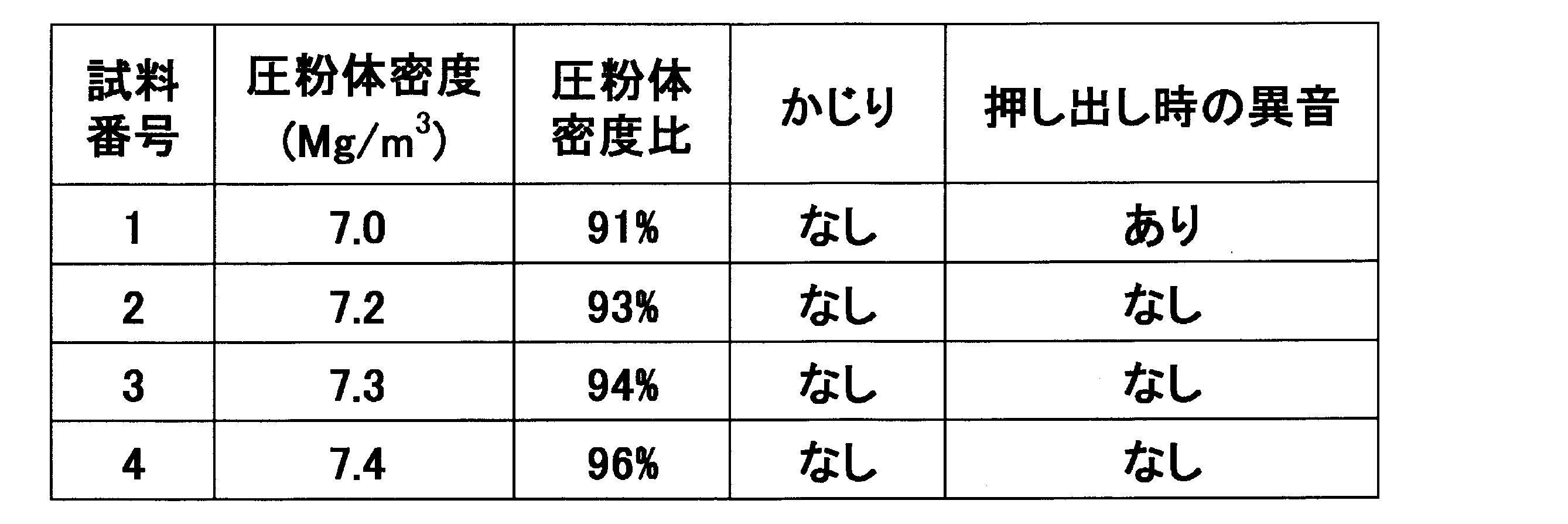
- Example 1 is applied to the inner surface of the outer mold to form a lubricant film having a thickness of 20 ⁇ m, filled with the raw material powder, and so that the density shown in Table 1 is obtained.
- a process of molding a cylindrical molded body (sample numbers 1 to 4) having a diameter of 20 mm and a height of 20 mm and extruding from an outer mold was repeated 20 times continuously for each sample number. For each sample, the presence or absence of galling on the wall surface of the pressing mold and the occurrence of abnormal noise during extrusion from the outer mold were observed. The results are shown in Table 1.
- the pressing lubricant is applied to the inner surface of the outer mold and the outer peripheral surface of the core rod for forming the gear shape to form a lubricating film having the thickness shown in Table 2, and the raw material powder
- the process of forming a module 2, a gear-shaped green compact with 23 teeth so as to have a density of 7.4 Mg / m 3 and extruding it from the outer mold is repeated 20 times for each sample number. It was.
- the thickness of the lubricating coating was measured using a Fourier transform infrared spectrophotometer manufactured by Shimadzu Corporation.
- the obtained green compact sample was sintered at 1130 ° C. in a non-oxidizing atmosphere, and the pore distribution of the tooth portion of the obtained sintered body sample was observed with an optical microscope. : Surface density was calculated by image analysis using WinROOF. In FIG. 4, the pore distribution photograph of the tooth
- the porosity of the surface layer portion of the sintered body was increased (density decreased) as the thickness of the lubricating coating increased. This is thought to be because the amount of the press lubricant that has entered the raw material increases, and the press lubricant remains caught in the compact without being squeezed out of the compact during the compression molding process. From the viewpoint of product characteristics such as strength, it was confirmed that the thickness of the lubricating coating is preferably 40 ⁇ m or less.
Landscapes
- Engineering & Computer Science (AREA)
- Mechanical Engineering (AREA)
- Chemical & Material Sciences (AREA)
- Chemical Kinetics & Catalysis (AREA)
- General Chemical & Material Sciences (AREA)
- Oil, Petroleum & Natural Gas (AREA)
- Organic Chemistry (AREA)
- Manufacturing & Machinery (AREA)
- Powder Metallurgy (AREA)
Abstract
Description
電解銅粉末(福田金属箔粉工業株式会社製、商品名:CE-15)、黒鉛粉末(Asbery Carbon社製、商品名:SW1651)、および鉄粉末(ヘガネスジャパン株式会社製、商品名:ABC100.30)を用意し、鉄粉末100質量部に電解銅粉末を1.5質量部、黒鉛粉末を0.8質量部添加し混合して原料粉末とした。
第1実施例で用いた原料と押型潤滑剤を用い、歯車形状を成形する外型内面およびコアロッド外周面に押型潤滑剤を塗布して表2に示す厚さの潤滑被膜を形成し、原料粉末を充填し、密度7.4Mg/m3となるようにモジュール2、歯数23の歯車形状の圧粉体を成形し、外型から押し出す、といった工程を、それぞれの試料番号につき連続20回繰り返した。なお、潤滑被膜の厚さは、株式会社島津製作所製のフーリエ変換赤外分光光度計を用いて測定した。また、比較として、ステアリン酸亜鉛をエタノールに分散して外型内面およびコアロッド外周面に塗布・乾燥して潤滑被膜を形成して原料粉末を充填し、密度7.4Mg/m3となるように上記の歯車形状の圧粉体を成形し、外型から押し出した。これら試料につき、押型壁面へのかじりの有無を観察した。結果を表2に示す。

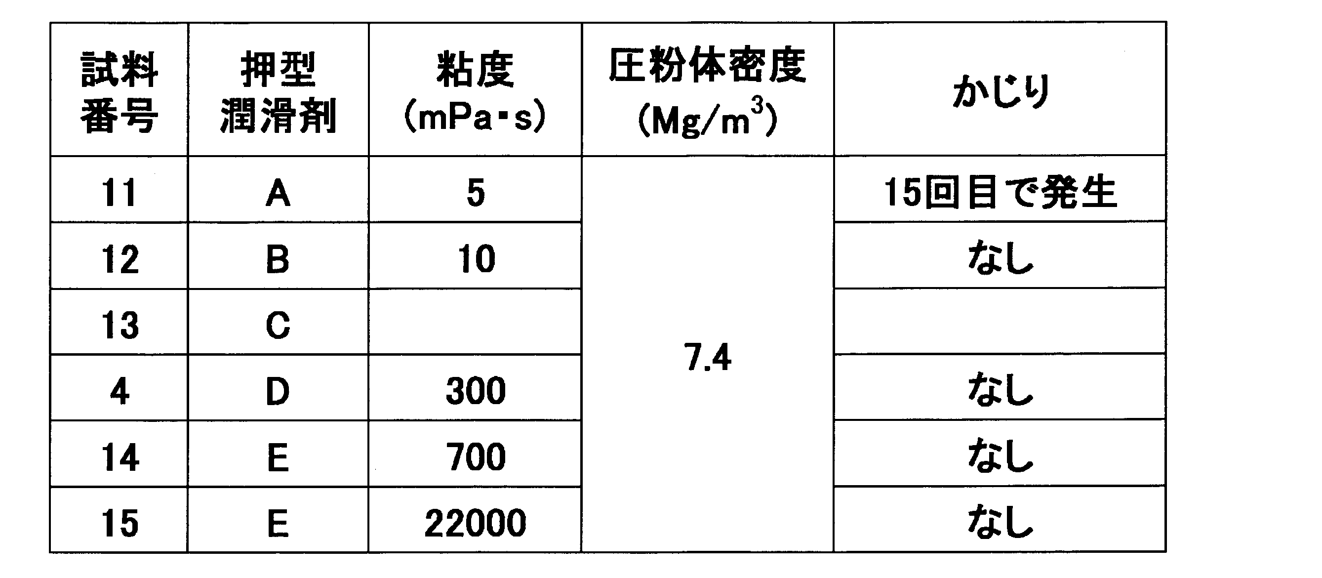
表3に示す押型潤滑剤A、B、C、E、Fを用いたこと以外は(押型潤滑剤Dは第1実施例で用いたもの)、第1実施例の試料番号4と同様にして、密度7.4Mg/m3の圧粉体の成形と、外型からの圧粉体の押し出しをそれぞれ連続20回繰り返し、押型壁面へのかじりの有無を観察した。結果を表4に示す。

Claims (6)
- 外型と下パンチ、または、外型と下パンチとコアロッドで形成するキャビティ内に充填した原料粉末を上パンチと下パンチの間に圧縮成形し、得られた成形体を下パンチで外型から押し出す成形体の成形方法において、
外型内面、または、外型内面およびコアロッドの外周面のうちの少なくとも一部に油を主成分とする押型潤滑剤の潤滑被膜を形成し、キャビティ内に原料粉末を充填し、成形体の密度比が93%以上となるように圧縮成形する押型法による成形体の成形方法。 - 前記下パンチが複数の下パンチで構成されるとともに、
側面が成形体の外周の一部を形成する下パンチのうちの少なくとも一つの下パンチの前記側面の一部に油を主成分とする押型潤滑剤の潤滑被膜を形成する請求項1に記載の押型法による成形体の成形方法。 - 前記上パンチが複数の上パンチで構成されるとともに、
側面が成形体の外周の一部を形成する上パンチのうちの少なくとも一つの上パンチの前記側面の一部に油を主成分とする押型潤滑剤の潤滑被膜を形成する請求項1または2に記載の押型法による成形体の成形方法。 - 潤滑被膜の厚さが5~40μmである請求項1~3のいずれかに記載の押型法による成形体の成形方法。
- 押型潤滑剤の25℃における粘度が10~100000mPa・sである請求項1~4のいずれかに記載の押型法による成形体の成形方法。
- 押型潤滑剤が固体潤滑剤を含有する請求項1~5のいずれかに記載の押型法による成形体の成形方法。
Priority Applications (4)
| Application Number | Priority Date | Filing Date | Title |
|---|---|---|---|
| US15/552,654 US10960633B2 (en) | 2015-03-20 | 2016-03-18 | Method for forming molded article by press molding |
| CN201680016946.4A CN107427917B (zh) | 2015-03-20 | 2016-03-18 | 基于压模法的成型体的成型方法 |
| EP16768681.5A EP3272443A4 (en) | 2015-03-20 | 2016-03-18 | Method for forming molded article by press molding |
| JP2017508316A JP6489331B2 (ja) | 2015-03-20 | 2016-03-18 | 押型法による成形体の成形方法 |
Applications Claiming Priority (2)
| Application Number | Priority Date | Filing Date | Title |
|---|---|---|---|
| JP2015-057780 | 2015-03-20 | ||
| JP2015057780 | 2015-03-20 |
Publications (1)
| Publication Number | Publication Date |
|---|---|
| WO2016152778A1 true WO2016152778A1 (ja) | 2016-09-29 |
Family
ID=56978568
Family Applications (1)
| Application Number | Title | Priority Date | Filing Date |
|---|---|---|---|
| PCT/JP2016/058705 WO2016152778A1 (ja) | 2015-03-20 | 2016-03-18 | 押型法による成形体の成形方法 |
Country Status (5)
| Country | Link |
|---|---|
| US (1) | US10960633B2 (ja) |
| EP (1) | EP3272443A4 (ja) |
| JP (2) | JP6489331B2 (ja) |
| CN (1) | CN107427917B (ja) |
| WO (1) | WO2016152778A1 (ja) |
Cited By (1)
| Publication number | Priority date | Publication date | Assignee | Title |
|---|---|---|---|---|
| JP2019065710A (ja) * | 2017-09-28 | 2019-04-25 | 日立化成株式会社 | スプロケット及びその製造方法 |
Families Citing this family (3)
| Publication number | Priority date | Publication date | Assignee | Title |
|---|---|---|---|---|
| EP3663020B1 (en) * | 2017-08-04 | 2021-06-16 | Sumitomo Electric Sintered Alloy, Ltd. | Method for manufacturing sintered component, and sintered component |
| JP2021098212A (ja) * | 2019-12-23 | 2021-07-01 | トヨタ自動車株式会社 | 塩中子の製造方法 |
| AT526261B1 (de) | 2022-07-05 | 2024-03-15 | Miba Sinter Austria Gmbh | Verfahren zur Herstellung eines Bauteils aus einem Sinterpulver |
Citations (7)
| Publication number | Priority date | Publication date | Assignee | Title |
|---|---|---|---|---|
| JPS4946506A (ja) * | 1972-08-29 | 1974-05-04 | ||
| JPS56158246A (en) * | 1980-05-02 | 1981-12-05 | Mazda Motor Corp | Production of core rod for powder molding |
| JPH0353001A (ja) * | 1989-07-20 | 1991-03-07 | Seiko Electronic Components Ltd | 耐食性被膜を持った焼結合金の製造方法 |
| JP2002100523A (ja) * | 2000-09-20 | 2002-04-05 | Daido Steel Co Ltd | 熱間塑性加工Nd−Fe−B系磁石の製造方法 |
| JP2003171701A (ja) * | 2001-12-10 | 2003-06-20 | Shin Etsu Chem Co Ltd | 希土類磁石の製造方法 |
| JP2010202933A (ja) * | 2009-03-04 | 2010-09-16 | Mitsubishi Materials Corp | 圧粉体の製造方法と複合軟磁性材の製造方法及びプレミックス粉末 |
| WO2015046282A1 (ja) * | 2013-09-27 | 2015-04-02 | 日立化成株式会社 | 圧粉磁心、磁心用圧粉体の製造方法、圧粉磁心製造用の押型及び金型装置、並びに、圧粉磁心製造用押型の潤滑組成物 |
Family Cites Families (35)
| Publication number | Priority date | Publication date | Assignee | Title |
|---|---|---|---|---|
| US3220092A (en) * | 1963-12-09 | 1965-11-30 | Powder Metal Products Inc | Method and apparatus for manufacturing composite bearings |
| US3366479A (en) * | 1965-04-28 | 1968-01-30 | Alloys Res & Mfg Corp | Powder metallurgy |
| DE1584605B1 (de) * | 1965-10-01 | 1970-03-12 | Nukem Gmbh | Vorrichtung zum Herstellen von Presslingen aus keramischen Pulvern |
| DE1920308B1 (de) * | 1969-04-22 | 1971-03-04 | Nukem Gmbh | Vorrichtung zur schmierung von presswerkzeugen fuer pulver metallurgische zwecke |
| JPS4937165B1 (ja) * | 1969-08-30 | 1974-10-07 | ||
| US3687657A (en) * | 1971-06-24 | 1972-08-29 | Samuel Storchheim | Air sintering of aluminum powder compacts |
| JPS4937165A (ja) * | 1972-08-09 | 1974-04-06 | ||
| US4244738A (en) * | 1978-03-24 | 1981-01-13 | Samuel Storchheim | Method of and apparatus for hot pressing particulates |
| JPS55141501A (en) | 1979-04-19 | 1980-11-05 | Fukuda Kinzoku Hakufun Kogyo Kk | Powder for infiltration material |
| US4338750A (en) * | 1980-10-28 | 1982-07-13 | General Electric Company | Method for applying organopolysiloxane fluids to grinding wheels containing cubic boron nitride abrasives |
| DE3049326A1 (de) * | 1980-12-29 | 1982-07-08 | Alkem Gmbh, 6450 Hanau | "verfahren zum herstellen von presslingen aus keramischem pulver, z.b. pulverfoermigen kernreaktorbrennstoffen und presseinrichtung, insbesondere fuer dieses verfahren" |
| DE3102196C2 (de) * | 1981-01-23 | 1983-03-17 | A. Kettenbach Fabrik Chemischer Erzeugnisse Dental-Spezialitäten GmbH & Co KG, 6345 Eschenburg | Verfahren zur Erzeugung einer gegenseitigen Haftung an der Grenzfläche zweier sich berührender Schichten aus Organopolysiloxanen |
| US5682591A (en) | 1994-08-24 | 1997-10-28 | Quebec Metal Powders Limited | Powder metallurgy apparatus and process using electrostatic die wall lubrication |
| EP0698435B1 (en) | 1994-08-24 | 2000-04-19 | Quebec Metal Powders Ltd. | Powder metallurgy apparatus and process using electrostatic die wall lubrication |
| JPH09272901A (ja) | 1996-04-08 | 1997-10-21 | Toyota Motor Corp | 粉末成形方法 |
| JP3512314B2 (ja) | 1997-06-25 | 2004-03-29 | 日立粉末冶金株式会社 | 磁性流体含浸焼結滑り軸受及びその製造方法 |
| US20080219610A1 (en) * | 2004-10-18 | 2008-09-11 | Nsk Ltd. | Waterproof Grease Composition and Wheel-Supporting Roller Bearing |
| JP2009120918A (ja) * | 2007-11-16 | 2009-06-04 | Sumitomo Denko Shoketsu Gokin Kk | 焼結部品の製造方法 |
| RU2510707C2 (ru) * | 2008-11-26 | 2014-04-10 | Хеганес Аб (Пабл) | Смазка для композиций порошковой металлургии |
| JP5466067B2 (ja) * | 2010-03-31 | 2014-04-09 | 出光興産株式会社 | 粉末冶金用潤滑剤および金属粉末組成物 |
| JP5523223B2 (ja) * | 2010-07-01 | 2014-06-18 | 日立粉末冶金株式会社 | 焼結含油軸受 |
| JP5739121B2 (ja) * | 2010-07-30 | 2015-06-24 | 出光興産株式会社 | 潤滑油基油および潤滑油組成物 |
| JP5539159B2 (ja) | 2010-11-04 | 2014-07-02 | アイダエンジニアリング株式会社 | 混合粉末の高密度成形方法および高密度成形装置。 |
| JP2012234872A (ja) * | 2011-04-28 | 2012-11-29 | Sumitomo Electric Ind Ltd | 圧粉成形体の成形方法 |
| JP2012234871A (ja) | 2011-04-28 | 2012-11-29 | Sumitomo Electric Ind Ltd | 圧粉成形体の成形方法 |
| CN102211190B (zh) * | 2011-05-20 | 2012-09-19 | 北京科技大学 | 一种制备硬质合金空心球体的模具及制备方法 |
| JP5778993B2 (ja) * | 2011-05-26 | 2015-09-16 | 住友電気工業株式会社 | 圧粉成形体の成形方法 |
| US20150133353A1 (en) * | 2012-06-05 | 2015-05-14 | Jx Nippon Oil & Energy Corporation | Grease composition |
| KR101471744B1 (ko) | 2013-02-26 | 2014-12-10 | 김경운 | 분말 성형 프레스용 금형 윤활 시스템 |
| KR20150143721A (ko) * | 2013-04-18 | 2015-12-23 | 에보니크 오일 아디티페스 게엠베하 | 연료 소비를 감소시키기 위한 변속기 오일 제제 |
| JP2015010225A (ja) * | 2013-07-02 | 2015-01-19 | 三菱電線工業株式会社 | 樹脂組成物およびシール部材 |
| CN203444970U (zh) * | 2013-08-22 | 2014-02-19 | 浙江东阳东磁有限公司 | 大高径比辐射环的取向压制装置 |
| AR098232A1 (es) * | 2013-10-31 | 2016-05-18 | Cognoptix Inc | Métodos de preparación de una formulación oftálmica y usos de la misma |
| CN104368812A (zh) * | 2014-11-28 | 2015-02-25 | 中核(天津)科技发展有限公司 | 粘结钕铁硼磁体的压制模具 |
| WO2017018365A1 (ja) * | 2015-07-24 | 2017-02-02 | 株式会社青木科学研究所 | 高密度の焼結体を生産するための金型潤滑油、金型潤滑油のスプレー塗布装置、スプレー塗布装置を備えた圧粉体成形装置、それを用いた圧粉体成形方法、およびその方法によって得られる焼結体 |
-
2016
- 2016-03-18 EP EP16768681.5A patent/EP3272443A4/en active Pending
- 2016-03-18 WO PCT/JP2016/058705 patent/WO2016152778A1/ja active Application Filing
- 2016-03-18 JP JP2017508316A patent/JP6489331B2/ja active Active
- 2016-03-18 US US15/552,654 patent/US10960633B2/en active Active
- 2016-03-18 CN CN201680016946.4A patent/CN107427917B/zh active Active
-
2018
- 2018-12-12 JP JP2018232389A patent/JP2019077950A/ja active Pending
Patent Citations (7)
| Publication number | Priority date | Publication date | Assignee | Title |
|---|---|---|---|---|
| JPS4946506A (ja) * | 1972-08-29 | 1974-05-04 | ||
| JPS56158246A (en) * | 1980-05-02 | 1981-12-05 | Mazda Motor Corp | Production of core rod for powder molding |
| JPH0353001A (ja) * | 1989-07-20 | 1991-03-07 | Seiko Electronic Components Ltd | 耐食性被膜を持った焼結合金の製造方法 |
| JP2002100523A (ja) * | 2000-09-20 | 2002-04-05 | Daido Steel Co Ltd | 熱間塑性加工Nd−Fe−B系磁石の製造方法 |
| JP2003171701A (ja) * | 2001-12-10 | 2003-06-20 | Shin Etsu Chem Co Ltd | 希土類磁石の製造方法 |
| JP2010202933A (ja) * | 2009-03-04 | 2010-09-16 | Mitsubishi Materials Corp | 圧粉体の製造方法と複合軟磁性材の製造方法及びプレミックス粉末 |
| WO2015046282A1 (ja) * | 2013-09-27 | 2015-04-02 | 日立化成株式会社 | 圧粉磁心、磁心用圧粉体の製造方法、圧粉磁心製造用の押型及び金型装置、並びに、圧粉磁心製造用押型の潤滑組成物 |
Non-Patent Citations (1)
| Title |
|---|
| See also references of EP3272443A4 * |
Cited By (1)
| Publication number | Priority date | Publication date | Assignee | Title |
|---|---|---|---|---|
| JP2019065710A (ja) * | 2017-09-28 | 2019-04-25 | 日立化成株式会社 | スプロケット及びその製造方法 |
Also Published As
| Publication number | Publication date |
|---|---|
| JPWO2016152778A1 (ja) | 2017-11-02 |
| US20180036984A1 (en) | 2018-02-08 |
| EP3272443A4 (en) | 2018-12-26 |
| JP2019077950A (ja) | 2019-05-23 |
| JP6489331B2 (ja) | 2019-03-27 |
| CN107427917B (zh) | 2020-02-28 |
| CN107427917A (zh) | 2017-12-01 |
| US10960633B2 (en) | 2021-03-30 |
| EP3272443A1 (en) | 2018-01-24 |
Similar Documents
| Publication | Publication Date | Title |
|---|---|---|
| JP2019077950A (ja) | 押型法による成形体の成形方法 | |
| TWI294317B (en) | Method for making compacted products and powder composition | |
| JP2012167302A (ja) | 粉末冶金用粉末混合物およびその製造方法 | |
| AU2005257719B2 (en) | Lubricants for insulated soft magnetic iron-based powder compositions | |
| JP5352978B2 (ja) | 焼結軸受の製造方法 | |
| WO2011048754A1 (ja) | 鍛造成型加工用潤滑油組成物および鍛造成型装置 | |
| US6365094B1 (en) | Lubricated die | |
| TW201712109A (zh) | 用來生產高密度燒結體的模具潤滑油、模具潤滑油的噴霧塗佈裝置、具備噴霧塗佈裝置的壓粉體成形裝置、使用該裝置的壓粉體成形方法及藉由該方法所獲得的燒結體 | |
| JP3462378B2 (ja) | 粉末冶金における粉末成形方法 | |
| KR20110118283A (ko) | 무급유 방청 소결 베어링 | |
| JP2015531027A (ja) | 金属粉末からの部品の製造に潤滑複合材を使用する技術 | |
| JP4353512B2 (ja) | 圧粉磁心の成形方法 | |
| JP2009091661A (ja) | 複合材料、複合材料の製造方法及び該複合材料を用いた摺動部材 | |
| RU2773772C1 (ru) | Состав спеченного фрикционного материала на основе меди | |
| JP2003080337A (ja) | 加圧成形方法および加圧成形部材 | |
| JP2001131606A (ja) | 粉末成形用コアロッドおよびそれを用いた圧粉成形方法 | |
| JP6948251B2 (ja) | 焼結含油軸受及びその製造方法 | |
| JP2009074159A (ja) | 圧粉体の製造方法、複合軟磁性材の製造方法、焼結体の製造方法、及びプレミックス粉末 | |
| CN108380863B (zh) | 粉末冶金用混合粉末及其制造方法 | |
| KR102048386B1 (ko) | 고체 윤활층을 포함하는 복합 베어링 및 그 제조방법 | |
| CN106544133A (zh) | 一种普通黄铜合金挤压加工工艺润滑剂组合物 | |
| WO2021070712A1 (ja) | 焼結含油軸受 | |
| JP4624214B2 (ja) | 粉末冶金における粉末成形方法および焼結部品の製造方法 | |
| JP2007296551A (ja) | 粉末成形方法 | |
| JP6849459B2 (ja) | 粉末冶金用混合粉末 |
Legal Events
| Date | Code | Title | Description |
|---|---|---|---|
| 121 | Ep: the epo has been informed by wipo that ep was designated in this application |
Ref document number: 16768681 Country of ref document: EP Kind code of ref document: A1 |
|
| ENP | Entry into the national phase |
Ref document number: 2017508316 Country of ref document: JP Kind code of ref document: A |
|
| WWE | Wipo information: entry into national phase |
Ref document number: 15552654 Country of ref document: US |
|
| NENP | Non-entry into the national phase |
Ref country code: DE |
|
| REEP | Request for entry into the european phase |
Ref document number: 2016768681 Country of ref document: EP |