WO2016143328A1 - ガラスパネルユニットの製造方法およびガラス窓の製造方法 - Google Patents
ガラスパネルユニットの製造方法およびガラス窓の製造方法 Download PDFInfo
- Publication number
- WO2016143328A1 WO2016143328A1 PCT/JP2016/001248 JP2016001248W WO2016143328A1 WO 2016143328 A1 WO2016143328 A1 WO 2016143328A1 JP 2016001248 W JP2016001248 W JP 2016001248W WO 2016143328 A1 WO2016143328 A1 WO 2016143328A1
- Authority
- WO
- WIPO (PCT)
- Prior art keywords
- glass substrate
- glass
- panel unit
- space
- manufacturing
- Prior art date
Links
Images


Classifications
-
- E—FIXED CONSTRUCTIONS
- E06—DOORS, WINDOWS, SHUTTERS, OR ROLLER BLINDS IN GENERAL; LADDERS
- E06B—FIXED OR MOVABLE CLOSURES FOR OPENINGS IN BUILDINGS, VEHICLES, FENCES OR LIKE ENCLOSURES IN GENERAL, e.g. DOORS, WINDOWS, BLINDS, GATES
- E06B3/00—Window sashes, door leaves, or like elements for closing wall or like openings; Layout of fixed or moving closures, e.g. windows in wall or like openings; Features of rigidly-mounted outer frames relating to the mounting of wing frames
- E06B3/66—Units comprising two or more parallel glass or like panes permanently secured together
- E06B3/673—Assembling the units
- E06B3/67326—Assembling spacer elements with the panes
-
- B—PERFORMING OPERATIONS; TRANSPORTING
- B28—WORKING CEMENT, CLAY, OR STONE
- B28D—WORKING STONE OR STONE-LIKE MATERIALS
- B28D1/00—Working stone or stone-like materials, e.g. brick, concrete or glass, not provided for elsewhere; Machines, devices, tools therefor
- B28D1/22—Working stone or stone-like materials, e.g. brick, concrete or glass, not provided for elsewhere; Machines, devices, tools therefor by cutting, e.g. incising
- B28D1/24—Working stone or stone-like materials, e.g. brick, concrete or glass, not provided for elsewhere; Machines, devices, tools therefor by cutting, e.g. incising with cutting discs
-
- C—CHEMISTRY; METALLURGY
- C03—GLASS; MINERAL OR SLAG WOOL
- C03B—MANUFACTURE, SHAPING, OR SUPPLEMENTARY PROCESSES
- C03B33/00—Severing cooled glass
- C03B33/07—Cutting armoured, multi-layered, coated or laminated, glass products
-
- C—CHEMISTRY; METALLURGY
- C03—GLASS; MINERAL OR SLAG WOOL
- C03C—CHEMICAL COMPOSITION OF GLASSES, GLAZES OR VITREOUS ENAMELS; SURFACE TREATMENT OF GLASS; SURFACE TREATMENT OF FIBRES OR FILAMENTS MADE FROM GLASS, MINERALS OR SLAGS; JOINING GLASS TO GLASS OR OTHER MATERIALS
- C03C27/00—Joining pieces of glass to pieces of other inorganic material; Joining glass to glass other than by fusing
- C03C27/06—Joining glass to glass by processes other than fusing
-
- E—FIXED CONSTRUCTIONS
- E06—DOORS, WINDOWS, SHUTTERS, OR ROLLER BLINDS IN GENERAL; LADDERS
- E06B—FIXED OR MOVABLE CLOSURES FOR OPENINGS IN BUILDINGS, VEHICLES, FENCES OR LIKE ENCLOSURES IN GENERAL, e.g. DOORS, WINDOWS, BLINDS, GATES
- E06B3/00—Window sashes, door leaves, or like elements for closing wall or like openings; Layout of fixed or moving closures, e.g. windows in wall or like openings; Features of rigidly-mounted outer frames relating to the mounting of wing frames
- E06B3/66—Units comprising two or more parallel glass or like panes permanently secured together
- E06B3/6621—Units comprising two or more parallel glass or like panes permanently secured together with special provisions for fitting in window frames or to adjacent units; Separate edge protecting strips
-
- E—FIXED CONSTRUCTIONS
- E06—DOORS, WINDOWS, SHUTTERS, OR ROLLER BLINDS IN GENERAL; LADDERS
- E06B—FIXED OR MOVABLE CLOSURES FOR OPENINGS IN BUILDINGS, VEHICLES, FENCES OR LIKE ENCLOSURES IN GENERAL, e.g. DOORS, WINDOWS, BLINDS, GATES
- E06B3/00—Window sashes, door leaves, or like elements for closing wall or like openings; Layout of fixed or moving closures, e.g. windows in wall or like openings; Features of rigidly-mounted outer frames relating to the mounting of wing frames
- E06B3/66—Units comprising two or more parallel glass or like panes permanently secured together
- E06B3/673—Assembling the units
-
- E—FIXED CONSTRUCTIONS
- E06—DOORS, WINDOWS, SHUTTERS, OR ROLLER BLINDS IN GENERAL; LADDERS
- E06B—FIXED OR MOVABLE CLOSURES FOR OPENINGS IN BUILDINGS, VEHICLES, FENCES OR LIKE ENCLOSURES IN GENERAL, e.g. DOORS, WINDOWS, BLINDS, GATES
- E06B3/00—Window sashes, door leaves, or like elements for closing wall or like openings; Layout of fixed or moving closures, e.g. windows in wall or like openings; Features of rigidly-mounted outer frames relating to the mounting of wing frames
- E06B3/66—Units comprising two or more parallel glass or like panes permanently secured together
- E06B3/677—Evacuating or filling the gap between the panes ; Equilibration of inside and outside pressure; Preventing condensation in the gap between the panes; Cleaning the gap between the panes
- E06B3/6775—Evacuating or filling the gap during assembly
-
- E—FIXED CONSTRUCTIONS
- E06—DOORS, WINDOWS, SHUTTERS, OR ROLLER BLINDS IN GENERAL; LADDERS
- E06B—FIXED OR MOVABLE CLOSURES FOR OPENINGS IN BUILDINGS, VEHICLES, FENCES OR LIKE ENCLOSURES IN GENERAL, e.g. DOORS, WINDOWS, BLINDS, GATES
- E06B3/00—Window sashes, door leaves, or like elements for closing wall or like openings; Layout of fixed or moving closures, e.g. windows in wall or like openings; Features of rigidly-mounted outer frames relating to the mounting of wing frames
- E06B3/66—Units comprising two or more parallel glass or like panes permanently secured together
- E06B3/663—Elements for spacing panes
- E06B3/66304—Discrete spacing elements, e.g. for evacuated glazing units
-
- E—FIXED CONSTRUCTIONS
- E06—DOORS, WINDOWS, SHUTTERS, OR ROLLER BLINDS IN GENERAL; LADDERS
- E06B—FIXED OR MOVABLE CLOSURES FOR OPENINGS IN BUILDINGS, VEHICLES, FENCES OR LIKE ENCLOSURES IN GENERAL, e.g. DOORS, WINDOWS, BLINDS, GATES
- E06B3/00—Window sashes, door leaves, or like elements for closing wall or like openings; Layout of fixed or moving closures, e.g. windows in wall or like openings; Features of rigidly-mounted outer frames relating to the mounting of wing frames
- E06B3/66—Units comprising two or more parallel glass or like panes permanently secured together
- E06B3/673—Assembling the units
- E06B3/67339—Working the edges of already assembled units
- E06B3/6736—Heat treatment
-
- E—FIXED CONSTRUCTIONS
- E06—DOORS, WINDOWS, SHUTTERS, OR ROLLER BLINDS IN GENERAL; LADDERS
- E06B—FIXED OR MOVABLE CLOSURES FOR OPENINGS IN BUILDINGS, VEHICLES, FENCES OR LIKE ENCLOSURES IN GENERAL, e.g. DOORS, WINDOWS, BLINDS, GATES
- E06B9/00—Screening or protective devices for wall or similar openings, with or without operating or securing mechanisms; Closures of similar construction
- E06B9/24—Screens or other constructions affording protection against light, especially against sunshine; Similar screens for privacy or appearance; Slat blinds
Definitions
- the present invention relates to a method for manufacturing a glass panel unit and a method for manufacturing a glass window, and more specifically, a method for manufacturing a glass panel unit in which a first glass substrate and a second glass substrate are bonded via a sealing material, and the glass panel.
- the present invention relates to a method for manufacturing a glass window including a unit.
- Patent Document 1 describes a glass panel unit in which a pair of glass substrates positioned opposite to each other are bonded together with a sealing material.
- Each of the pair of glass substrates is a glass substrate previously formed in a predetermined size and shape, and the outer peripheral edge portions of the pair of glass substrates are bonded to each other with a sealing material.
- Patent Document 1 in a conventional method of manufacturing a glass panel unit, a pair of glass substrates is cut into a predetermined size and shape in advance. Then, in the sealing furnace, the pair of glass substrates is heated with the sealing material sandwiched therebetween, and the pair of glass substrates are bonded to each other through the sealing material, thereby obtaining a glass panel unit having a desired size and shape. It is done.
- the problem to be solved by the present invention is to efficiently manufacture a glass panel unit having a desired size and shape and a glass window having the glass panel unit.
- a method for manufacturing a glass panel unit according to an aspect of the present invention includes an arrangement step, a joining step, and a cutting step.
- the first glass substrate and the second glass substrate are arranged so as to face each other with the sealing material interposed therebetween.
- the first glass substrate and the second glass substrate are bonded to each other via the sealing material.
- the first glass substrate, the sealing material, and the second glass substrate are assumed to pass through the sealing material from one side of the bonded first glass substrate and second glass substrate. Cut along a general cut surface.
- the manufacturing method of the glass window which concerns on 1 aspect of this invention is equipped with the assembly process which inserts a window frame in the glass panel unit manufactured with the manufacturing method of the glass panel unit which concerns on 1 aspect of this invention.
- the said process process is a process by which the air of the said interior space is discharged
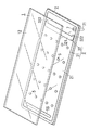
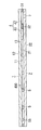
- Drawing 1 is a perspective view explaining the arrangement process of the manufacturing method of the glass panel unit of a first embodiment.
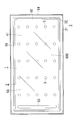
- Drawing 2 is a top view explaining the arrangement process and joining process of the manufacturing method of the glass panel unit of a first embodiment.
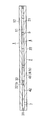
- 3 is a cross-sectional view taken along line AA in FIG.
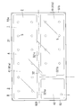
- FIG. 4 is a partially broken plan view illustrating a processing step and a cutting step of the glass panel unit manufacturing method according to the first embodiment.
- FIG. 5 is principal part sectional drawing explaining the cutting process of the manufacturing method of the glass panel unit of 1st embodiment.
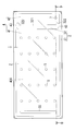
- FIG. 6 is a plan view showing the glass panel unit manufactured by the glass panel unit manufacturing method of the first embodiment.
- 7 is a cross-sectional view taken along line BB in FIG. FIG.
- FIG. 8 is a flowchart for explaining the method for manufacturing the glass panel unit of the first embodiment.
- FIG. 9 is a plan view for explaining an arrangement step and a joining step of the glass panel unit manufacturing method according to the second embodiment.
- 10 is a cross-sectional view taken along the line CC of FIG.
- FIG. 11 is a plan view illustrating a processing step and a cutting step of the glass panel unit manufacturing method according to the second embodiment.
- FIG. 12: is a top view explaining the arrangement
- 13 is a cross-sectional view taken along the line DD of FIG.
- FIG. 14 is a partially broken plan view illustrating a processing step and a cutting step of the glass panel unit manufacturing method according to the third embodiment.
- FIG. 15 is principal part sectional drawing explaining the cutting process of the manufacturing method of the glass panel unit of 4th embodiment.
- FIG. 16 is principal part sectional drawing explaining the cutting process of the manufacturing method of the glass panel unit of 4th embodiment.
- FIG. 17 is principal part sectional drawing explaining the cutting process of the manufacturing method of the glass panel unit of 4th embodiment.
- FIG. 18 is a flowchart for explaining a manufacturing method of the glass panel unit of the fourth embodiment.
- FIG. 19 is a plan view showing a glass panel unit manufactured by the glass panel unit manufacturing method of the fifth embodiment.
- 20 is a cross-sectional view taken along the line EE of FIG.
- FIG. 21 is a flowchart for explaining a manufacturing method of the glass panel unit of the fifth embodiment.
- FIG. 19 is a plan view showing a glass panel unit manufactured by the glass panel unit manufacturing method of the fifth embodiment.
- FIG. 22 is a plan view showing a glass window including the glass panel unit of the first embodiment.
- FIG. 23 is a flowchart showing a method for manufacturing a glass window including the glass panel unit of the first embodiment.
- FIG. 24 is a plan view showing a glass window including the glass panel unit of the fifth embodiment.
- FIG. 25 is a flowchart showing a method for manufacturing a glass window including the glass panel unit of the fifth embodiment.
- Glass panel unit of the first embodiment The manufacturing method of the glass panel unit of 1st embodiment is provided with arrangement
- Arrangement step S1 is a step in which the first glass substrate 1 and the second glass substrate 2 are arranged so as to face each other with the sealing material 3 interposed therebetween (see FIGS. 1 to 3).
- the bonding step S2 is a step in which the first glass substrate 1 and the second glass substrate 2 arranged in the arrangement step S1 are bonded to each other via the sealing material 3. Thereby, an internal space 4 is formed between the first glass substrate 1 and the second glass substrate 2, and the internal space 4 is separated from the first space 41 and the second space by a part of the sealing material 3 (partition material 32). 42 (see FIGS. 2 and 3). The first space 41 and the second space 42 communicate with each other through the ventilation path 43.
- the air in the internal space 4 (the first space 41 and the second space 42) is discharged through the vent hole 7 provided in the second glass substrate 2, and then a part of the sealing material 3 (the partition material 32). ) Is a step of sealing the first space 41 (see FIG. 4).
- the cutting step S4 is a virtual process in which the first glass substrate 1, the sealing material 3, and the second glass substrate 2 pass through a part of the sealing material 3 (the deformed partition material 32) from the first glass substrate 1 side. This is a process of cutting along the cutting plane 900 and physically separating the first space 41 and the second space 42 (see FIGS. 4 to 7).
- the first glass substrate 1 is a rectangular flat plate having a first surface 11 on one side in the thickness direction and a second surface 12 on the other side in the thickness direction.
- the first surface 11 and the second surface 12 of the first glass substrate 1 are planes parallel to each other.
- the material of the first glass substrate 1 is, for example, soda lime glass, high strain point glass, chemically tempered glass, alkali-free glass, quartz glass, neoceram, and physically tempered glass.
- the first surface 11 of the first glass substrate 1 is constituted by the outer surface of the coating 13 (see FIG. 3).
- the coating 13 is, for example, an infrared reflecting film, but may be a film having other physical characteristics. It is also possible not to provide the coating 13 on the first glass substrate 1.
- the second glass substrate 2 is a rectangular flat plate, like the first glass substrate 1.
- the second glass substrate 2 has a first surface 21 on one side in the thickness direction and a second surface 22 on the other side in the thickness direction.
- the first surface 21 and the second surface 22 of the second glass substrate 2 are planes parallel to each other. Vent holes 7 are formed in corner portions of the second glass substrate 2.
- the material of the second glass substrate 2 is, for example, soda lime glass, high strain point glass, chemically tempered glass, alkali-free glass, quartz glass, neoceram, or physically tempered glass.
- the first glass substrate 1 and the second glass substrate 2 are arranged so as to face each other. At this time, the first surface 11 of the first glass substrate 1 and the first surface 21 of the second glass substrate 2 are positioned in parallel and facing each other (see FIG. 3).
- the sealing material 3 is disposed between the first glass substrate 1 and the second glass substrate 2.
- the sealing material 3 includes a rectangular frame-shaped frame material 31 and a partition material 32.
- the frame member 31 and the partition member 32 are disposed on the first surface 21 of the second glass substrate 2.
- the frame member 31 is disposed along the outer peripheral edge of the second glass substrate 2, and the partition member 32 is disposed so as to be surrounded by the frame member 31.
- the first glass substrate 1 and the second glass substrate 2 are joined in an airtight manner via a sealing material 3 (frame material 31 and partition material 32). Thereby, an internal space 4 is formed between the first glass substrate 1 and the second glass substrate 2.
- the internal space 4 is a space surrounded by the frame material 31, the first glass substrate 1, and the second glass substrate 2.
- Both the frame member 31 and the partition member 32 are formed of glass frit (glass paste).
- the glass frit is a low-melting glass frit such as a bismuth glass frit, a lead glass frit, or a vanadium glass frit.
- the partition member 32 includes a straight wall portion 321 and a pair of blocking portions 322 extending from both ends of the wall portion 321 in the length direction.
- the pair of blocking portions 322 each extend in a direction orthogonal to the length direction of the wall portion 321.
- An air passage 43 is formed between the partition member 32 and the frame member 31.
- the space formed between one end in the length direction of the wall portion 321 and the frame member 31 and the space formed between the other end in the length direction of the wall portion 321 and the frame member 31 are respectively ventilated.
- the position and number of the air passages 43 are not limited to this.
- the plurality of spacers 5 are arranged on the first surface 21 of the second glass substrate 2.
- the plurality of spacers 5 are used to maintain the distance between the first glass substrate 1 and the second glass substrate 2 at a predetermined distance.
- the plurality of spacers 5 are each formed in a cylindrical shape using a transparent material.
- the material of each spacer 5, the size of each spacer 5, the shape of each spacer 5, the spacing between adjacent spacers 5, the arrangement pattern of the plurality of spacers 5, etc. can be selected as appropriate. Further, it is possible that only one spacer 5 is disposed or the spacer 5 is not disposed.
- the gas adsorber 55 is disposed on the first surface 21 of the second glass substrate 2. On the first surface 21, the gas adsorber 55 is located away from the partition member 32 and the air passage 43. The gas adsorber 55 is used to adsorb gas released from the frame member 31 and the partition member 32 during heating. Note that the gas adsorber 55 may be included in the plurality of spacers 5 or the gas adsorber 55 may not be disposed.
- the temperature in the sealing furnace is determined to be a predetermined temperature equal to or higher than the softening point of the frame member 31 (hereinafter referred to as “first melting temperature”).
- first melting temperature the softening point of the frame member 31
- the first glass substrate 1 and the second glass substrate 2 disposed in the sealing furnace are heated for a predetermined time at the first melting temperature.
- the first melting temperature and the predetermined time are determined so that the air passage 43 is not blocked by the partition member 32.
- an internal space 4 surrounded by a frame material 31 is formed between the first glass substrate 1 and the second glass substrate 2 bonded together.
- the internal space 4 is partitioned into a first space 41 and a second space 42 by a partition member 32.
- the first space 41 and the second space 42 can be ventilated via the vent passage 43 positioned between the frame member 31 and the partition member 32.
- the first space 41 is a space on the side where the plurality of spacers 5 and the gas adsorber 55 are located.
- the second space 42 is a space on the side continuous with the vent hole 7.
- the vent hole 7 communicates the second space 42 and the external space.
- the vent hole 7 of the present embodiment is used for exhausting the first space 41 through the second space 42 and the vent path 43.
- the processing step S3 is a step in which the internal space 4 is a vacuum space, and includes an exhaust step and a sealing step.
- the evacuation process and the sealing process of the processing process S3 are performed in the sealing furnace following the joining process S2.
- the exhaust process is a process in which the air in the internal space 4 is discharged to the outside through the vent hole 7 and the entire internal space 4 is evacuated.
- the air in the first space 41 is discharged to the outside through the ventilation path 43, the second space 42, and the ventilation hole 7, and the pressure is reduced until the first space 41 reaches the vacuum space.
- the This exhausting operation is performed using, for example, a vacuum pump via an exhaust pipe 71 (see FIG. 1) connected to the second glass substrate 2 so as to communicate with the vent hole 7.
- the evacuation time is determined so as to obtain a vacuum space having a desired degree of vacuum (for example, a degree of vacuum of 0.1 Pa or less).
- the partition member 32 is melted at a predetermined temperature equal to or higher than the softening point of the partition member 32 (hereinafter referred to as “second melting temperature”), and the partition member 32 is deformed so as to close the air passage 43.
- second melting temperature the softening point of the partition member 32
- the partition member 32 is deformed so that the blocking portion 322 on one end side of the partition member 32 closes the one air passage 43 and the blocking portion 322 on the other end side closes the other air passage 43. (See FIGS. 2 and 4).
- the deformed partition member 32 functions as a partition that hermetically separates the vacuum internal space 4 from the first space 41 and the second space 42.
- the second melting temperature at which the partition member 32 is melted is determined to be higher than the first melting temperature.
- the partition member 32 is provided so as to be deformed at a temperature higher than the first melting temperature and to block the air passage 43.
- the temporary assembly unit 8 including the first space 41 that is a vacuum space as shown in FIG. 4 is obtained.
- the temporary assembly unit 8 taken out from the sealing furnace is cut along the virtual cutting surface 900 shown in FIGS. 4 and 5, and a portion 81 having a first space 41 and a second space 42 are obtained. Is physically separated into a portion 82 having The cut surface 900 is provided so as to pass through the partition member 32 over its entire length in a plan view (when the second surface 12 of the first glass substrate 1 is viewed in front).
- the cutting device 9 is a scribing device including a cutting wheel 91 at the tip.
- the wheel 91 of the cutting device 9 moves along the cutting surface 900 while pressing against one surface side (the second surface 12 of the first glass substrate 1) of the temporary assembly unit 8, so that the first glass substrate 1 and the sealing material are moved. 3 and the second glass substrate 2 are collectively cut along the cut surface 900.
- the partition member 32 is obtained by once melting the glass frit, in the temporary assembly unit 8, the first glass substrate 1 and the second glass substrate 2 are firmly integrated via the partition member 32. Yes. Therefore, when the wheel 91 is pressed against one side and moves, cracks deeply occur in the thickness direction of the first glass substrate 1 and the second glass substrate 2, and the first glass substrate 1, the partitioning material 32, and the second glass substrate 2 are It is cut smoothly along the cutting surface 900 like a single glass plate. That is, the temporary assembly unit 8 is smoothly cut as if it were a single glass panel, without requiring a cleaving operation after scribing.
- one part 81 divided is used as a glass panel unit (insulating glass panel unit).
- the other divided part 82 is an extra part.
- the cross section 811 of the part 81 used as the glass panel unit the cross sections of the first glass substrate 1, the sealing material 3 (partition material 32), and the second glass substrate 2 are flush with each other (FIGS. 6 and 7). reference). Therefore, the strength is ensured and the handleability is good at a stage where the cross section 811 is not further processed. Further, the cross section 811 may be further processed.
- the cutting device 9 preferably further has a mechanism for applying vibration to the wheel 91.
- the direction in which the vibration is applied is the thickness direction of the first glass substrate 1 or the second glass substrate 2, in other words, the direction in which the first glass substrate 1, the partition member 32, and the second glass substrate 2 are laminated. .
- this vibration is applied during the cutting operation, the first glass substrate 1, the partition member 32, and the second glass substrate 2 are more likely to be cut together.
- the cutting device 9 may come into contact with the second glass substrate 2 and cut the temporary assembly unit 8 along the cut surface 900.
- other devices such as a device for jetting water jets and a device for cutting by laser irradiation may be used.
- Glass panel unit of the second embodiment The manufacturing method of the glass panel unit of 2nd embodiment is demonstrated based on FIG.9, FIG10 and FIG.11.
- symbol is attached
- detailed description is abbreviate
- the temporary assembly unit 8 is formed so that two glass panel units can be obtained from one temporary assembly unit 8.
- a process for obtaining two glass panel units includes an arrangement process S1, a joining process S2, a processing process S3 (exhaust process, sealing process), and a cutting process S4.
- the first glass substrate 1 and the second glass substrate 2 are arranged so as to face each other with the sealing material 3 (the frame material 31 and the partition material 32) interposed therebetween.
- the bonding step S ⁇ b> 2 the first glass substrate 1 and the second glass substrate 2 are bonded to each other via the sealing material 3.
- the internal space 4 surrounded by the frame member 31 between the first glass substrate 1 and the second glass substrate 2 is partitioned into two first spaces 41 and one second space 42 by a partition member 32 ( (See FIG. 9).
- reference numeral 41 a is assigned to one first space 41
- reference numeral 41 b is assigned to the other first space 41.
- the partition member 32 of the present embodiment includes a wall portion 321a that partitions one of the first spaces 41a and the second space 42, a wall portion 321b that partitions the other first space 41b and the second space 42, and one first space. 41a and a wall portion 321c that partitions the other first space 41b.
- the partition member 32 includes two ventilation paths 43.
- reference numeral 43 a is assigned to one air passage 43
- reference numeral 43 b is attached to the other air passage 43.
- the ventilation path 43a is formed in the wall portion 321a, and the first space 41a and the second space 42 are communicated with each other through the ventilation path 43a.
- the ventilation path 43b is formed in the wall portion 321b, and the first space 41b and the second space 42 are communicated with each other through the ventilation path 43b so as to allow ventilation.
- the position and the number of the ventilation paths 43a and the ventilation paths 43b are not limited to this.
- the wall portion 321a and the wall portion 321b of the partition member 32 are deformed by heating, so that the air passage 43a and the air passage 43b are both blocked so as not to be ventilated.
- the temporary assembly unit 8 provided with the 1st space 41a and the 1st space 41b which became a vacuum space as shown in FIG. 11 is obtained.
- the temporary assembly unit 8 is cut along a virtual cut surface 900 shown in FIG.
- the temporary assembly unit 8 is physically divided into a portion 81a having the sealed first space 41a, a portion 81b having the sealed first space 41b, and a portion 82 having the second space 42.
- a cutting device 9 as shown in FIG. 5 is preferably used.
- a portion 81a including the first vacuum space 41a and a portion 81b including the first vacuum space 41b are both used as a glass panel unit (insulating glass panel unit).
- the portion 82 including the second space 42 and the vent hole 7 is an extra portion.
- the temporary assembly unit 8 has a structure in which the first glass substrate 1, the sealing material 3, and the second glass substrate 2 are laminated, but the cut surface 900 that passes through the sealing material 3 (partition material 32). Are cut in a lump as if one glass plate was cut.
- the temporary assembly unit 8 is formed so that two glass panel units can be obtained. However, three or more glass panel units can be obtained (that is, three or more multi-faces can be obtained). It is possible that a temporary assembly unit 8 is formed.
- Glass panel unit of the third embodiment A method for manufacturing the glass panel unit according to the third embodiment will be described with reference to FIGS.
- symbol is attached
- detailed description is abbreviate
- a glass panel unit is obtained by passing through arrangement process S1, joining process S2, processing process S3, and cutting process S4.
- the pressure is not reduced until the internal space 4 becomes vacuum in the processing step S3, but the entire internal space 4 is filled with the gas 400 through the vent hole 7 and the vent passage 43 (see FIG. 12), and then the sealing material. 3 (partition material 32) is deformed by heating, and the first space 41 is sealed.
- the gas 400 is a gas having a low thermal conductivity such as dry air or argon gas.
- the temporary assembly unit 8 including the first space 41 filled with the gas 400 as shown in FIG. 14 is obtained through the processing step S3.
- the temporary assembly unit 8 is cut along the cutting surface 900 and physically separated into a portion 81 having the first space 41 and a portion 82 having the second space 42.
- the cut surface 900 is provided in a straight line so as to pass through the partition member 32 over its entire length.
- One portion 81 of the temporary assembly unit 8 is used as a glass panel unit (insulating glass panel unit) in which a gas 400 is filled between the first glass substrate 1 and the second glass substrate 2.
- the other part 82 including the second space 42 is an extra part.
- Glass panel unit of the fourth embodiment A method for manufacturing a glass panel unit according to the fourth embodiment will be described with reference to FIGS.
- symbol is attached
- detailed description is abbreviate
- a glass substrate in which wires 25 are embedded is used as the second glass substrate 2.
- the wire 25 is provided in a net shape, for example.
- the manufacturing method of the glass panel unit of this embodiment includes a wire cutting step S5 in addition to the placement step S1, the joining step S2, the processing step S3, and the cutting step S4.
- the placement step S1, the joining step S2, and the processing step S3 of the present embodiment are the same as in the first embodiment.
- the cutting step S4 and the wire cutting step S5 will be described in detail.
- the temporary assembly unit 8 is held with the first glass substrate 1 positioned above the second glass substrate 2 and the second surface 12 of the first glass substrate 1 facing upward, and the cutting device 9
- the wheel 91 moves along the cut surface 900 while pressing against the second surface 12 of the first glass substrate 1 from above.
- the crack 61 along the cut surface 900 propagates from the second surface 12 (upper surface) of the first glass substrate 1 toward the second glass substrate 2 (see FIG. 15).
- the crack 61 further grows along the cut surface 900, The first glass substrate 1, the sealing material 3, and the second glass substrate 2 are collectively cut by the grown crack 61.
- the wire 25 remains without being cut.
- the wire cutting step S5 is a step in which the wire 25 of the second glass substrate 2 is cut after the first glass substrate 1, the sealing material 3 and the second glass substrate 2 are cut together in the cutting step S4.
- the wire 25 is buried in one part 81 (part used as a glass panel unit) of the temporary assembly unit 8 and the other part 82 (excess part). It is divided into wires 252. It is preferable that the wire 251 be appropriately processed so as not to jump out of the cross section 811.
- the crack 61 is propagated from the first glass substrate 1 side, and the temporary assembly unit 8 is folded with the second glass substrate 2 having the wires 25 inside, so that breakage may occur during cutting. It can be suppressed.
- the glass is likely to hit the inner region of the bent wire 25 (region 62 in FIG. 16), but this region 62 has a short distance from the wire 25. , Hitting with a large force is suppressed, and damage is prevented from occurring.
- the glass substrate in which the wires 25 are embedded is used as the second glass substrate 2, the crack 61 is inserted from the first glass substrate 1 side, and the second glass substrate 2 is placed inside. Then, the wire 25 of the second glass substrate 2 can be cut after the first glass substrate 1, the sealing material 3 and the second glass substrate 2 are collectively cut.
- Glass panel unit of the fifth embodiment A method for manufacturing a glass panel unit according to the fifth embodiment will be described with reference to FIGS.
- symbol is attached
- detailed description is abbreviate
- the first glass substrate 1 and the third glass substrate 63 are bonded via the frame-shaped second sealing material 64, and a second internal space 65 surrounded by the second sealing material 64 is formed. Process.
- the material of the third glass substrate 63 is, for example, soda lime glass, high strain point glass, chemically tempered glass, alkali-free glass, quartz glass, neoceram, or physically tempered glass.
- a hollow frame-like spacer 66 is further arranged inside the second seal material 64.
- the hollow portion of the spacer 66 is filled with a desiccant 67.
- the spacer 66 is made of a metal such as aluminum and has a through hole 661 on the inner peripheral side.
- the hollow portion of the spacer 66 communicates with the second internal space 65 through the through hole 661.
- the desiccant 67 is, for example, silica gel.
- the second sealing material 64 is made of a highly airtight resin such as silicon resin or butyl rubber.
- the second internal space 65 is a space sealed from the outside.
- the second internal space 65 is filled with a dry gas 600.
- the dry gas 600 is, for example, a dry rare gas such as argon, dry air, or the like.
- the dry air includes air that is sealed in the second internal space 65 and then dried by the action of the desiccant 67.
- the first space 41 decompressed to a vacuum and the dry gas 600 between the third glass substrate 63 and the second glass substrate 2 located on both sides in the thickness direction. Since the second internal space 65 filled with is interposed, it has higher heat insulation.
- the third glass substrate 63 is disposed to face the first glass substrate 1, but the third glass substrate 63 can be disposed to face the second glass substrate 2.
- the peripheral edges of the second glass substrate 2 and the third glass substrate 63 are arranged with the spacer 66 sandwiched between the second glass substrate 2 and the third glass substrate 63.
- the second sealing material 64 is joined. Thereby, a second internal space 65 is formed between the second glass substrate 2 and the third glass substrate 63.
- the second to fourth embodiments also include a second bonding step S6, and one of the first glass substrate 1 and the second glass substrate 2 cut in the cutting step S4, and the third glass substrate 63. It is possible to join the two through a frame-like second sealing material 64. Also in this case, the heat insulation is further improved by forming the second internal space 65 surrounded by the frame-shaped second sealing material 64.
- Glass window comprising the glass panel unit of the first to fourth embodiments
- the manufacturing method of a glass window provided with the glass panel unit of 1st embodiment is demonstrated based on FIG. 22, FIG.
- a glass window is constituted by the glass panel unit of the first embodiment and the window frame 68.
- the glass window manufacturing method includes each step S1 in addition to the placement step S1, the joining step S2, the processing step S3, and the cutting step S4 included in the glass panel unit manufacturing method of the first embodiment. , S2, S3, S4, and further includes an assembly step S7 for fitting the rectangular window frame 68 into the glass panel unit manufactured through S4. In the process step S3, the air in the internal space 4 is discharged.
- the glass window manufactured by this method has a structure in which a window frame 68 is fitted in a glass panel unit having a first space 41 between the first glass substrate 1 and the second glass substrate 2, and the first space 41 is By being decompressed, it has high heat insulation.
- the window frame 68 in the similar assembly step S7. Also in this case, the glass window manufactured through the assembling step S7 has a high heat insulating property by having the decompressed first space 41 between the first glass substrate 1 and the second glass substrate 2.
- Glass window comprising the glass panel unit of the fifth embodiment
- the manufacturing method of a glass window provided with the glass panel unit of 5th embodiment is demonstrated based on FIG. 24, FIG.
- the glass panel unit of the fifth embodiment and the window frame 69 constitute a glass window.
- the glass window manufacturing method includes an arrangement step S1, a bonding step S2, a processing step S3, a cutting step S4, and a second bonding step S6 included in the glass panel unit manufacturing method of the fifth embodiment.
- it further includes an assembly step S8 in which the window frame 69 is fitted into the glass panel unit manufactured through the steps S1, S2, S3, S4, and S6.
- the air in the internal space 4 is discharged.
- the second internal space 65 formed in the second bonding step S6 is a space in which the dry gas 600 is enclosed.
- the glass window manufactured by this method has a structure in which a window frame 69 is fitted in a glass panel unit having a first space 41 and a second internal space 65, and has a high heat insulating property.
- the vent hole 7 is formed in the second glass substrate 2, but the vent hole 7 is formed in at least one of the first glass substrate 1 and the second glass substrate 2. Good. That is, the vent hole 7 may be formed in the first glass substrate 1, or the vent hole 7 may be formed in both the first glass substrate 1 and the second glass substrate 2.
- the internal space 4 is depressurized until it becomes a vacuum space.
- the gas 400 is sealed in the internal space 4, but the internal space 4 is not depressurized.
- the gas 400 may not be sealed. Also in this case, heat insulation is obtained by interposing the internal space 4 between the first glass substrate 1 and the second glass substrate 2.
- the internal space 4 is partitioned into one first space 41 and one second space 42.
- the internal space 4 is divided into two first spaces 41.
- the partition of the internal space 4 is not limited to these forms. That is, the internal space 4 may be partitioned into one or more first spaces 41 and one or more second spaces 42 by the partition member 32. From the temporary assembly unit 8, the same number of glass panel units as the number of the first spaces 41 formed in the internal space 4 can be obtained.
- the sealing material 3 includes the partition material 32, but the partition material 32 may not be included. Also in this case, by cutting the first glass substrate 1, the sealing material 3, and the second glass substrate 2 together along a virtual cutting surface 900 that passes through the sealing material 3, it is as if a single glass plate is formed. A smooth cross section as if cut is obtained.
- the glass panel unit according to the first to fifth embodiments and the glass window including these glass panel units have been described based on the attached drawings. It is also possible to apply combinations of the configurations of the embodiments as appropriate.
- the glass panel unit manufacturing method according to the first embodiment includes an arrangement step S1, a joining step S2, and a cutting step S4.
- the first glass substrate 1 and the second glass substrate 2 are arranged so as to face each other with the sealing material 3 interposed therebetween.
- the bonding step S ⁇ b> 2 the first glass substrate 1 and the second glass substrate 2 are bonded to each other via the sealing material 3.
- the cutting step S ⁇ b> 4 the first glass substrate 1, the sealing material 3, and the second glass substrate 2 are assumed to pass through the sealing material 3 from one side of the bonded first glass substrate 1 and second glass substrate 2. Cut along a general cutting plane 900.
- the first glass substrate 1 and the second glass substrate 2 are joined to form the temporary assembly unit 8, and then the temporary assembly unit 8 is cut.
- a dimensionally shaped glass panel unit can be obtained. Therefore, a glass panel unit having a desired dimension and shape can be efficiently manufactured, and a plurality of glass panel units can be obtained from one temporary assembly unit 8.
- the production efficiency may decrease.
- the first embodiment by preparing a sealing furnace corresponding to the temporary assembly unit 8, It is possible to suppress a large free space. In other words, it is not necessary to prepare a dedicated sealing furnace for each type (size and shape) of the glass panel unit to be manufactured in order to suppress the generation of a large empty space in the furnace.
- the first glass substrate 1 and the second glass substrate 2 bonded to each other via the sealing material 3 are along the virtual cut surface 900 that passes through the sealing material 3. It is cut in a lump and smoothly as if a single glass plate was cut. Since the cross section 811 cut along the cut surface 900 is formed to be flush with the cross section of a single glass plate, the strength is ensured and the handleability is also good without further processing. .
- the manufacturing method of the glass panel unit of the 2nd form is additionally provided with the following composition in the 1st form. That is, the second embodiment further includes a wire cutting step S5.
- the second glass substrate 2 is a glass substrate in which wires 25 are embedded.
- the crack 61 is propagated from the first glass substrate 1 to the second glass substrate 2 along the virtual cutting plane 900, and the first glass substrate 1, the sealing material 3, and the second glass substrate 2 are In this process, the second glass substrate 2 is turned inside and the crack 61 is folded.
- the wire cutting step S5 is a step of cutting the wire 25 of the second glass substrate 2 after the cutting step S4.
- the strength of the second glass substrate 2 is increased by the wires 25, and the strength of the entire glass panel unit is improved.
- the occurrence of breakage when the first glass substrate 1 and the second glass substrate 2 are cut together is suppressed.
- the manufacturing method of the glass panel unit of the 3rd form is additionally provided with the following composition in the 2nd form. That is, in the third embodiment, in the cutting step S4, the first glass substrate 1 is positioned above the second glass substrate 2, and the crack 61 is propagated from the upper surface of the first glass substrate 1.
- the crack 91 is generated by pressing the wheel 91 against the first glass substrate 1 from above, and the first part is lifted so that the part where the crack 61 is generated is lifted from the other part.
- the first glass substrate 1, the sealing material 3, and the second glass substrate 2 are collectively cut.
- the manufacturing method of the glass panel unit of a 4th form is additionally provided with the following structure in any one of the 1st thru
- the heat insulation of a glass panel unit improves because the internal space 4 interposes between the 1st glass substrate 1 and the 2nd glass substrate 2.
- the manufacturing method of the glass panel unit of a 5th form is further equipped with the following structure in a 4th form. That is, the fifth embodiment further includes a processing step S3 in which the air in the internal space 4 is discharged or the gas 400 is supplied to the internal space 4.
- the heat insulation of a glass panel unit is carried out by interposing the internal space 4 decompressed or filled with the gas 400. Further improve. That is, according to the fifth embodiment, it is possible to efficiently manufacture a glass panel unit having a desired dimensional shape and high heat insulation.
- the manufacturing method of the glass panel unit of the sixth form additionally includes the following configuration in the fifth form. That is, in the sixth embodiment, the sealing material 3 further includes a partition member 32 that partitions the internal space 4 into a plurality of spaces 41 and 42 (41a, 41b, and 42). In the cutting step S ⁇ b> 3, the first glass substrate 1, the partition material 32, and the second glass substrate 2 are collectively cut along the cut surface 900 that passes through the partition material 32.
- the sixth embodiment by cutting the temporary assembly unit 8 along the partition member 32, it is possible to efficiently manufacture a glass panel unit having a desired dimensional shape and high heat insulation.
- the manufacturing method of the glass panel unit according to the seventh aspect additionally includes the following configuration in the sixth aspect. That is, in the seventh embodiment, in the bonding step S2, the first glass substrate 1 and the second glass substrate 2 are bonded to each other via the frame material 31, and the internal space 4 is divided into a plurality of spaces 41 and 42 by the partition material 32. (41a, 41b, 42). In addition, in the joining step S2, a ventilation path 43 (43a, 43b) that allows the plurality of spaces 41, 42 (41a, 41b, 42) to vent each other is provided.
- the air passages 43 (43a, 43b) are closed to thereby close the plurality of spaces 41, 42 (41a , 41b, 42) become impermeable to each other.
- the cutting step S ⁇ b> 4 the first glass substrate 1, the partition material 32, and the second glass substrate 2 are collectively cut along the cut surface 900 that passes through the partition material 32.
- the seventh embodiment it is possible to efficiently manufacture a glass panel unit having a desired dimensional shape and high heat insulating properties.
- the manufacturing method of the glass panel unit according to the eighth aspect additionally has the following configuration in the sixth aspect. That is, in the eighth embodiment, at least one of the first glass substrate 1 and the second glass substrate 2 includes the vent hole 7.
- the internal space 4 is partitioned by the partition material 32 into a first space 41 (41 a, 41 b) that is not continuous with the vent hole 7 and a second space 42 that is continuous with the vent hole 7.
- the ventilation path 43 (43a, 43b) which enables the 1st space 41 (41a, 41b) and the 2nd space 42 to ventilate mutually is provided.
- the vent path 43 (43a, 43b) is closed to thereby close the first space. 41 (41a, 41b) is sealed.
- the cutting step S ⁇ b> 4 the first glass substrate 1, the partition material 32, and the second glass substrate 2 are collectively cut along the cut surface 900 that passes through the partition material 32. And the part 81 in which the 1st space 41 is located, and the part 82 in which the 2nd space 42 and the vent hole 7 are located are isolate
- the portion 81 (81a, 81b) including the first space 41 (41a, 41b) is excluded from the temporary assembly unit 8 except for the portion 82 where the second space 42 and the vent hole 7 are located. It can be provided as a glass panel unit with high heat insulation.
- the manufacturing method of the glass panel unit according to the ninth aspect additionally includes the following configuration in the fifth to eighth aspects. That is, the ninth embodiment further includes a second joining step S6. In the second bonding step S6, one of the first glass substrate 1 and the second glass substrate 2 cut in the cutting step S4 and the third glass substrate 63 are bonded via a frame-shaped second sealing material 64. In this step, the second internal space 65 surrounded by the second seal material 64 is formed.
- a glass panel unit further having a heat-insulating second internal space 65 is obtained. That is, according to the 9th form, a glass panel unit with still higher heat insulation is manufactured efficiently.
- the manufacturing method of the glass window of the 1st form is provided with assembly process S7 which inserts the window frame 68 in the glass panel unit manufactured with the manufacturing method of the glass panel unit of the 5th thru
- Processing step S3 is a step in which air in the internal space 4 is discharged.
- the first embodiment it is possible to efficiently manufacture a glass window having a desired dimension and shape and high heat insulation.
- the manufacturing method of the glass window of the 2nd form is provided with assembly process S8 which inserts the window frame 69 in the glass panel unit manufactured with the manufacturing method of the glass panel unit of the 9th form.
- Processing step S3 is a step in which air in the internal space 4 is discharged.
- the second internal space 65 formed in the second bonding step S6 is a space in which the dry gas 600 is enclosed.
- the second embodiment it is possible to efficiently manufacture a glass window having a desired size and shape and high heat insulation.
- Glass panel unit 11 Glass substrate (first glass substrate) 111 one side 12 glass substrate (second glass substrate) DESCRIPTION OF SYMBOLS 13 Seal material 14 Spacer 15 Internal space 100 Glass board
Landscapes
- Engineering & Computer Science (AREA)
- Chemical & Material Sciences (AREA)
- Structural Engineering (AREA)
- Civil Engineering (AREA)
- Organic Chemistry (AREA)
- Materials Engineering (AREA)
- Ceramic Engineering (AREA)
- Life Sciences & Earth Sciences (AREA)
- Chemical Kinetics & Catalysis (AREA)
- General Chemical & Material Sciences (AREA)
- Geochemistry & Mineralogy (AREA)
- Mechanical Engineering (AREA)
- Mining & Mineral Resources (AREA)
- Joining Of Glass To Other Materials (AREA)
- Re-Forming, After-Treatment, Cutting And Transporting Of Glass Products (AREA)
- Securing Of Glass Panes Or The Like (AREA)
- Processing Of Stones Or Stones Resemblance Materials (AREA)
Priority Applications (7)
| Application Number | Priority Date | Filing Date | Title |
|---|---|---|---|
| US15/555,917 US20180038152A1 (en) | 2015-03-11 | 2016-03-08 | Manufacturing method for glass panel unit and manufacturing method for glass window |
| CN201680015248.2A CN107406295B (zh) | 2015-03-11 | 2016-03-08 | 玻璃面板单元的制造方法和玻璃窗的制造方法 |
| JP2017504867A JP6601781B2 (ja) | 2015-03-11 | 2016-03-08 | ガラスパネルユニットの製造方法およびガラス窓の製造方法 |
| DK16761302.5T DK3269688T3 (da) | 2015-03-11 | 2016-03-08 | Fremgangsmåde til fremstilling af glasrudeenhed og fremgangsmåde til fremstilling af glasvindue |
| PL16761302T PL3269688T3 (pl) | 2015-03-11 | 2016-03-08 | Sposób wytwarzania jednostki panelu szklanego i sposób wytwarzania okna szklanego |
| EP16761302.5A EP3269688B1 (en) | 2015-03-11 | 2016-03-08 | Manufacturing method for glass panel unit and manufacturing method for glass window |
| ES16761302T ES2879275T3 (es) | 2015-03-11 | 2016-03-08 | Procedimiento de fabricación para una unidad de panel de vidrio y procedimiento de fabricación para una ventana de vidrio |
Applications Claiming Priority (2)
| Application Number | Priority Date | Filing Date | Title |
|---|---|---|---|
| JP2015-048566 | 2015-03-11 | ||
| JP2015048566 | 2015-03-11 |
Publications (1)
| Publication Number | Publication Date |
|---|---|
| WO2016143328A1 true WO2016143328A1 (ja) | 2016-09-15 |
Family
ID=56879518
Family Applications (1)
| Application Number | Title | Priority Date | Filing Date |
|---|---|---|---|
| PCT/JP2016/001248 WO2016143328A1 (ja) | 2015-03-11 | 2016-03-08 | ガラスパネルユニットの製造方法およびガラス窓の製造方法 |
Country Status (9)
| Country | Link |
|---|---|
| US (1) | US20180038152A1 (da) |
| EP (1) | EP3269688B1 (da) |
| JP (1) | JP6601781B2 (da) |
| CN (1) | CN107406295B (da) |
| DK (1) | DK3269688T3 (da) |
| ES (1) | ES2879275T3 (da) |
| HU (1) | HUE055124T2 (da) |
| PL (1) | PL3269688T3 (da) |
| WO (1) | WO2016143328A1 (da) |
Cited By (12)
| Publication number | Priority date | Publication date | Assignee | Title |
|---|---|---|---|---|
| WO2018062072A1 (ja) * | 2016-09-30 | 2018-04-05 | パナソニックIpマネジメント株式会社 | ガラスパネルユニットの製造方法、ガラス窓の製造方法、およびガラスパネルユニット |
| WO2018062071A1 (ja) * | 2016-09-30 | 2018-04-05 | パナソニックIpマネジメント株式会社 | ガラスパネルユニットの製造方法、およびガラス窓の製造方法 |
| WO2018062069A1 (ja) * | 2016-09-30 | 2018-04-05 | パナソニックIpマネジメント株式会社 | ガラスパネルユニットの製造方法、およびガラス窓の製造方法 |
| WO2019188312A1 (ja) * | 2018-03-30 | 2019-10-03 | パナソニックIpマネジメント株式会社 | ガラスパネルユニットの製造方法及びガラス窓の製造方法 |
| WO2019188766A1 (ja) | 2018-03-29 | 2019-10-03 | パナソニックIpマネジメント株式会社 | ガラスパネルユニットの仕掛り品、ガラスパネルユニットの製造方法 |
| WO2019207970A1 (ja) * | 2018-04-26 | 2019-10-31 | パナソニックIpマネジメント株式会社 | ガラスパネルユニットの組立て品、ガラスパネルユニットの製造方法 |
| WO2019207968A1 (ja) * | 2018-04-26 | 2019-10-31 | パナソニックIpマネジメント株式会社 | ガラスパネルユニットの組立て品、ガラスパネルユニットの製造方法、ガラスパネルユニットの仕掛り品、ガラスパネルユニット |
| WO2019230242A1 (ja) | 2018-05-31 | 2019-12-05 | パナソニックIpマネジメント株式会社 | ガラスパネルユニットの組立て品、ガラスパネルユニットの製造方法、ガラスパネルユニットの組立て品の製造方法 |
| WO2019230247A1 (ja) | 2018-05-31 | 2019-12-05 | パナソニックIpマネジメント株式会社 | ガラスパネルユニットの組立て品、ガラスパネルユニットの製造方法 |
| JPWO2018179994A1 (ja) * | 2017-03-31 | 2020-05-14 | パナソニックIpマネジメント株式会社 | ガラスパネルユニット、及びガラス窓 |
| US11162297B2 (en) * | 2018-04-26 | 2021-11-02 | Panasonic Intellectual Property Management Co., Ltd. | Glass panel unit assembly, and method for manufacturing glass panel unit |
| JP2021532044A (ja) * | 2018-07-31 | 2021-11-25 | フラウンホッファー−ゲゼルシャフト ツァー フェーデルング デア アンゲバンテン フォルシュング エー ファー | ガラスペインを成形する方法 |
Families Citing this family (2)
| Publication number | Priority date | Publication date | Assignee | Title |
|---|---|---|---|---|
| JP7033753B2 (ja) * | 2018-06-28 | 2022-03-11 | パナソニックIpマネジメント株式会社 | ピラー供給方法、ガラスパネルユニットの製造方法、及びピラー供給装置 |
| DE102019210574A1 (de) * | 2019-07-17 | 2021-01-21 | Schott Ag | Tür für ein Gefrier- oder Kühlmöbel |
Citations (6)
| Publication number | Priority date | Publication date | Assignee | Title |
|---|---|---|---|---|
| JPS4814766B1 (da) * | 1968-01-16 | 1973-05-10 | ||
| JPS5328614A (en) * | 1976-08-30 | 1978-03-17 | Nippon Sheet Glass Co Ltd | Method of separating metallwireereinforced glass |
| JPS54137358A (en) * | 1978-04-18 | 1979-10-25 | Seikosha Kk | Method of cutting glass |
| JP2002241149A (ja) * | 2001-02-14 | 2002-08-28 | Nippon Sheet Glass Co Ltd | ガラスパネル |
| JP2008003388A (ja) * | 2006-06-23 | 2008-01-10 | Rohm Co Ltd | フラットパネルディスプレイおよびその製造方法 |
| WO2013172034A1 (ja) * | 2012-05-18 | 2013-11-21 | パナソニック株式会社 | 複層ガラスの製造方法 |
Family Cites Families (11)
| Publication number | Priority date | Publication date | Assignee | Title |
|---|---|---|---|---|
| US3281298A (en) * | 1963-10-15 | 1966-10-25 | Pittsburgh Plate Glass Co | Manufacture of multiple glazing units |
| US4683154A (en) * | 1985-08-19 | 1987-07-28 | The United States Of America As Represented By The United States Department Of Energy | Laser sealed vacuum insulation window |
| TWI226877B (en) * | 2001-07-12 | 2005-01-21 | Mitsuboshi Diamond Ind Co Ltd | Method of manufacturing adhered brittle material substrates and method of separating adhered brittle material substrates |
| JP2006143506A (ja) * | 2004-11-18 | 2006-06-08 | Sanyo Electric Co Ltd | ガラス基板の切断方法 |
| JP4885675B2 (ja) * | 2006-09-27 | 2012-02-29 | 株式会社Nsc | 貼合せガラス板の切断分離方法 |
| CN102067017B (zh) * | 2008-09-12 | 2013-05-01 | 夏普株式会社 | 显示面板的制造方法 |
| JP5481167B2 (ja) * | 2009-11-12 | 2014-04-23 | 浜松ホトニクス株式会社 | ガラス溶着方法 |
| DE102010012265B4 (de) * | 2010-03-22 | 2012-09-06 | Fraunhofer-Gesellschaft zur Förderung der angewandten Forschung e.V. | Verfahren zum Heraustrennen von Einzelscheiben aus einer Verbundglastafel und Verwendung einer Vorrichtung dafür |
| JP6048091B2 (ja) * | 2011-12-28 | 2016-12-21 | 株式会社リコー | 通信装置、通信方法および通信プログラム |
| KR101581996B1 (ko) * | 2013-01-17 | 2015-12-31 | (주)엘지하우시스 | 분리 영역을 형성하는 실링재를 포함하는 진공유리 및 이를 이용하여 복수의 진공유리를 제조하는 방법 |
| US20150165563A1 (en) * | 2013-12-17 | 2015-06-18 | Corning Incorporated | Stacked transparent material cutting with ultrafast laser beam optics, disruptive layers and other layers |
-
2016
- 2016-03-08 EP EP16761302.5A patent/EP3269688B1/en active Active
- 2016-03-08 HU HUE16761302A patent/HUE055124T2/hu unknown
- 2016-03-08 ES ES16761302T patent/ES2879275T3/es active Active
- 2016-03-08 PL PL16761302T patent/PL3269688T3/pl unknown
- 2016-03-08 DK DK16761302.5T patent/DK3269688T3/da active
- 2016-03-08 WO PCT/JP2016/001248 patent/WO2016143328A1/ja active Application Filing
- 2016-03-08 US US15/555,917 patent/US20180038152A1/en not_active Abandoned
- 2016-03-08 JP JP2017504867A patent/JP6601781B2/ja active Active
- 2016-03-08 CN CN201680015248.2A patent/CN107406295B/zh active Active
Patent Citations (6)
| Publication number | Priority date | Publication date | Assignee | Title |
|---|---|---|---|---|
| JPS4814766B1 (da) * | 1968-01-16 | 1973-05-10 | ||
| JPS5328614A (en) * | 1976-08-30 | 1978-03-17 | Nippon Sheet Glass Co Ltd | Method of separating metallwireereinforced glass |
| JPS54137358A (en) * | 1978-04-18 | 1979-10-25 | Seikosha Kk | Method of cutting glass |
| JP2002241149A (ja) * | 2001-02-14 | 2002-08-28 | Nippon Sheet Glass Co Ltd | ガラスパネル |
| JP2008003388A (ja) * | 2006-06-23 | 2008-01-10 | Rohm Co Ltd | フラットパネルディスプレイおよびその製造方法 |
| WO2013172034A1 (ja) * | 2012-05-18 | 2013-11-21 | パナソニック株式会社 | 複層ガラスの製造方法 |
Cited By (39)
| Publication number | Priority date | Publication date | Assignee | Title |
|---|---|---|---|---|
| US11465938B2 (en) | 2016-09-30 | 2022-10-11 | Panasonic Intellectual Property Management Co., Ltd. | Manufacturing method of glass panel unit, manufacturing method of glass window, and glass panel unit |
| US11299422B2 (en) | 2016-09-30 | 2022-04-12 | Panasonic Intellectual Property Management Co., Ltd. | Method for producing insulating glass unit and method for producing glass window |
| WO2018062069A1 (ja) * | 2016-09-30 | 2018-04-05 | パナソニックIpマネジメント株式会社 | ガラスパネルユニットの製造方法、およびガラス窓の製造方法 |
| JPWO2018062072A1 (ja) * | 2016-09-30 | 2019-06-24 | パナソニックIpマネジメント株式会社 | ガラスパネルユニットの製造方法、ガラス窓の製造方法、およびガラスパネルユニット |
| JPWO2018062071A1 (ja) * | 2016-09-30 | 2019-07-18 | パナソニックIpマネジメント株式会社 | ガラスパネルユニットの製造方法、およびガラス窓の製造方法 |
| JPWO2018062069A1 (ja) * | 2016-09-30 | 2019-07-25 | パナソニックIpマネジメント株式会社 | ガラスパネルユニットの製造方法、およびガラス窓の製造方法 |
| EP3521255A4 (en) * | 2016-09-30 | 2019-09-25 | Panasonic Intellectual Property Management Co., Ltd. | METHOD FOR PRODUCING A GLASS WIPE AND METHOD FOR PRODUCING A GLASS WINDOW |
| US11193322B2 (en) | 2016-09-30 | 2021-12-07 | Panasonic Intellectual Property Management Co., Ltd. | Manufacturing method of glass panel unit and manufacturing method of glass window |
| JP6994675B2 (ja) | 2016-09-30 | 2022-01-14 | パナソニックIpマネジメント株式会社 | ガラスパネルユニットの製造方法、およびガラス窓の製造方法 |
| WO2018062072A1 (ja) * | 2016-09-30 | 2018-04-05 | パナソニックIpマネジメント株式会社 | ガラスパネルユニットの製造方法、ガラス窓の製造方法、およびガラスパネルユニット |
| JP2020164419A (ja) * | 2016-09-30 | 2020-10-08 | パナソニックIpマネジメント株式会社 | ガラスパネルユニットの製造方法、およびガラス窓の製造方法 |
| WO2018062071A1 (ja) * | 2016-09-30 | 2018-04-05 | パナソニックIpマネジメント株式会社 | ガラスパネルユニットの製造方法、およびガラス窓の製造方法 |
| JPWO2018179994A1 (ja) * | 2017-03-31 | 2020-05-14 | パナソニックIpマネジメント株式会社 | ガラスパネルユニット、及びガラス窓 |
| JPWO2019188766A1 (ja) * | 2018-03-29 | 2021-04-08 | パナソニックIpマネジメント株式会社 | ガラスパネルユニットの仕掛り品、ガラスパネルユニットの製造方法 |
| JP7016050B2 (ja) | 2018-03-29 | 2022-02-04 | パナソニックIpマネジメント株式会社 | ガラスパネルユニットの仕掛り品、ガラスパネルユニットの製造方法 |
| WO2019188766A1 (ja) | 2018-03-29 | 2019-10-03 | パナソニックIpマネジメント株式会社 | ガラスパネルユニットの仕掛り品、ガラスパネルユニットの製造方法 |
| JP7113298B2 (ja) | 2018-03-30 | 2022-08-05 | パナソニックIpマネジメント株式会社 | ガラスパネルユニットの製造方法及びガラス窓の製造方法 |
| WO2019188312A1 (ja) * | 2018-03-30 | 2019-10-03 | パナソニックIpマネジメント株式会社 | ガラスパネルユニットの製造方法及びガラス窓の製造方法 |
| JPWO2019188312A1 (ja) * | 2018-03-30 | 2021-03-18 | パナソニックIpマネジメント株式会社 | ガラスパネルユニットの製造方法及びガラス窓の製造方法 |
| US11767706B2 (en) | 2018-03-30 | 2023-09-26 | Panasonic Intellectual Property Management Co., Ltd. | Method for manufacturing glass panel unit, and method for manufacturing glass window |
| JPWO2019207970A1 (ja) * | 2018-04-26 | 2021-05-20 | パナソニックIpマネジメント株式会社 | ガラスパネルユニットの組立て品、ガラスパネルユニットの製造方法 |
| US11428041B2 (en) | 2018-04-26 | 2022-08-30 | Panasonic Intellectual Property Management Co., Ltd. | Glass panel unit assembly, method for manufacturing glass panel unit, work in progress of glass panel unit, and glass panel unit |
| WO2019207970A1 (ja) * | 2018-04-26 | 2019-10-31 | パナソニックIpマネジメント株式会社 | ガラスパネルユニットの組立て品、ガラスパネルユニットの製造方法 |
| US11162297B2 (en) * | 2018-04-26 | 2021-11-02 | Panasonic Intellectual Property Management Co., Ltd. | Glass panel unit assembly, and method for manufacturing glass panel unit |
| WO2019207968A1 (ja) * | 2018-04-26 | 2019-10-31 | パナソニックIpマネジメント株式会社 | ガラスパネルユニットの組立て品、ガラスパネルユニットの製造方法、ガラスパネルユニットの仕掛り品、ガラスパネルユニット |
| EP3786125A4 (en) * | 2018-04-26 | 2021-06-23 | Panasonic Intellectual Property Management Co., Ltd. | GLASS UNIT ARRANGEMENT, MANUFACTURING METHOD FOR GLASS UNIT |
| JP7149622B2 (ja) | 2018-04-26 | 2022-10-07 | パナソニックIpマネジメント株式会社 | ガラスパネルユニットの製造方法 |
| US11230878B2 (en) | 2018-04-26 | 2022-01-25 | Panasonic Intellectual Property Management Co., Ltd. | Glass panel unit assembly and method for manufacturing glass panel unit |
| JPWO2019207968A1 (ja) * | 2018-04-26 | 2021-05-13 | パナソニックIpマネジメント株式会社 | ガラスパネルユニットの組立て品、ガラスパネルユニットの製造方法、ガラスパネルユニットの仕掛り品、ガラスパネルユニット |
| WO2019230247A1 (ja) | 2018-05-31 | 2019-12-05 | パナソニックIpマネジメント株式会社 | ガラスパネルユニットの組立て品、ガラスパネルユニットの製造方法 |
| WO2019230242A1 (ja) | 2018-05-31 | 2019-12-05 | パナソニックIpマネジメント株式会社 | ガラスパネルユニットの組立て品、ガラスパネルユニットの製造方法、ガラスパネルユニットの組立て品の製造方法 |
| JP7117656B2 (ja) | 2018-05-31 | 2022-08-15 | パナソニックIpマネジメント株式会社 | ガラスパネルユニットの組立て品、ガラスパネルユニットの製造方法 |
| JP7117655B2 (ja) | 2018-05-31 | 2022-08-15 | パナソニックIpマネジメント株式会社 | ガラスパネルユニットの組立て品、ガラスパネルユニットの製造方法、ガラスパネルユニットの組立て品の製造方法 |
| EP3805172A4 (en) * | 2018-05-31 | 2021-07-07 | Panasonic Intellectual Property Management Co., Ltd. | ASSEMBLY OF GLASS PANEL UNITS AND METHOD OF MANUFACTURING A GLASS PANEL UNIT |
| JPWO2019230247A1 (ja) * | 2018-05-31 | 2021-06-17 | パナソニックIpマネジメント株式会社 | ガラスパネルユニットの組立て品、ガラスパネルユニットの製造方法 |
| US11549305B2 (en) | 2018-05-31 | 2023-01-10 | Panasonic Intellectual Property Management Co., Ltd. | Glass panel unit assembly, and method for manufacturing glass panel unit |
| JPWO2019230242A1 (ja) * | 2018-05-31 | 2021-07-08 | パナソニックIpマネジメント株式会社 | ガラスパネルユニットの組立て品、ガラスパネルユニットの製造方法、ガラスパネルユニットの組立て品の製造方法 |
| JP2021532044A (ja) * | 2018-07-31 | 2021-11-25 | フラウンホッファー−ゲゼルシャフト ツァー フェーデルング デア アンゲバンテン フォルシュング エー ファー | ガラスペインを成形する方法 |
| US11939253B2 (en) | 2018-07-31 | 2024-03-26 | Fraunhofer-Gesellschaft zur Förderung der angewandten Forschung e.V. | Method for shaping glass panes |
Also Published As
| Publication number | Publication date |
|---|---|
| DK3269688T3 (da) | 2021-06-14 |
| US20180038152A1 (en) | 2018-02-08 |
| EP3269688A1 (en) | 2018-01-17 |
| EP3269688A4 (en) | 2018-03-28 |
| HUE055124T2 (hu) | 2021-11-29 |
| CN107406295B (zh) | 2020-08-18 |
| ES2879275T3 (es) | 2021-11-22 |
| PL3269688T3 (pl) | 2021-11-02 |
| EP3269688B1 (en) | 2021-04-28 |
| CN107406295A (zh) | 2017-11-28 |
| JPWO2016143328A1 (ja) | 2018-02-22 |
| JP6601781B2 (ja) | 2019-11-06 |
Similar Documents
| Publication | Publication Date | Title |
|---|---|---|
| JP6601781B2 (ja) | ガラスパネルユニットの製造方法およびガラス窓の製造方法 | |
| JP6471916B2 (ja) | ガラスパネルユニット、ガラスパネルユニットの仮組立て品、ガラスパネルユニットの組立て品、ガラスパネルユニットの製造方法 | |
| JP6635386B2 (ja) | 真空ガラスパネルの製造方法 | |
| CN107074642B (zh) | 玻璃面板单元的制造方法 | |
| JP6528335B2 (ja) | ガラスパネルユニット | |
| US11117831B2 (en) | Glass panel unit, glass window, and method for manufacturing glass panel unit | |
| WO2017056422A1 (ja) | ガラスパネルユニットおよびガラス窓 | |
| WO2017056419A1 (ja) | ガラスパネルユニットの製造方法およびガラス窓の製造方法 | |
| JP6775205B2 (ja) | ガラスパネルユニットの製造方法、およびガラス窓の製造方法 | |
| JP7113298B2 (ja) | ガラスパネルユニットの製造方法及びガラス窓の製造方法 | |
| WO2018062124A1 (ja) | ガラスパネルユニットの製造方法およびガラス窓の製造方法 | |
| WO2018062072A1 (ja) | ガラスパネルユニットの製造方法、ガラス窓の製造方法、およびガラスパネルユニット | |
| WO2018062071A1 (ja) | ガラスパネルユニットの製造方法、およびガラス窓の製造方法 | |
| JP7336728B2 (ja) | ガラスパネルユニットの製造方法 | |
| WO2019207971A1 (ja) | ガラスパネルユニット、ガラスパネルユニットの仕掛り品、ガラスパネルユニットの組立て品、ガラスパネルユニットの製造方法 |
Legal Events
| Date | Code | Title | Description |
|---|---|---|---|
| 121 | Ep: the epo has been informed by wipo that ep was designated in this application |
Ref document number: 16761302 Country of ref document: EP Kind code of ref document: A1 |
|
| REEP | Request for entry into the european phase |
Ref document number: 2016761302 Country of ref document: EP |
|
| WWE | Wipo information: entry into national phase |
Ref document number: 15555917 Country of ref document: US |
|
| ENP | Entry into the national phase |
Ref document number: 2017504867 Country of ref document: JP Kind code of ref document: A |
|
| NENP | Non-entry into the national phase |
Ref country code: DE |