WO2016035894A1 - Procédé de fabrication d'article moulé à surface modifiée, et procédé de fabrication de composite à l'aide d'article moulé à surface modifiée - Google Patents
Procédé de fabrication d'article moulé à surface modifiée, et procédé de fabrication de composite à l'aide d'article moulé à surface modifiée Download PDFInfo
- Publication number
- WO2016035894A1 WO2016035894A1 PCT/JP2015/075272 JP2015075272W WO2016035894A1 WO 2016035894 A1 WO2016035894 A1 WO 2016035894A1 JP 2015075272 W JP2015075272 W JP 2015075272W WO 2016035894 A1 WO2016035894 A1 WO 2016035894A1
- Authority
- WO
- WIPO (PCT)
- Prior art keywords
- molded body
- silver
- integer
- compound
- modified
- Prior art date
Links
Images

Classifications
-
- B—PERFORMING OPERATIONS; TRANSPORTING
- B29—WORKING OF PLASTICS; WORKING OF SUBSTANCES IN A PLASTIC STATE IN GENERAL
- B29C—SHAPING OR JOINING OF PLASTICS; SHAPING OF MATERIAL IN A PLASTIC STATE, NOT OTHERWISE PROVIDED FOR; AFTER-TREATMENT OF THE SHAPED PRODUCTS, e.g. REPAIRING
- B29C71/00—After-treatment of articles without altering their shape; Apparatus therefor
- B29C71/04—After-treatment of articles without altering their shape; Apparatus therefor by wave energy or particle radiation, e.g. for curing or vulcanising preformed articles
-
- C—CHEMISTRY; METALLURGY
- C08—ORGANIC MACROMOLECULAR COMPOUNDS; THEIR PREPARATION OR CHEMICAL WORKING-UP; COMPOSITIONS BASED THEREON
- C08J—WORKING-UP; GENERAL PROCESSES OF COMPOUNDING; AFTER-TREATMENT NOT COVERED BY SUBCLASSES C08B, C08C, C08F, C08G or C08H
- C08J5/00—Manufacture of articles or shaped materials containing macromolecular substances
- C08J5/12—Bonding of a preformed macromolecular material to the same or other solid material such as metal, glass, leather, e.g. using adhesives
-
- B—PERFORMING OPERATIONS; TRANSPORTING
- B29—WORKING OF PLASTICS; WORKING OF SUBSTANCES IN A PLASTIC STATE IN GENERAL
- B29C—SHAPING OR JOINING OF PLASTICS; SHAPING OF MATERIAL IN A PLASTIC STATE, NOT OTHERWISE PROVIDED FOR; AFTER-TREATMENT OF THE SHAPED PRODUCTS, e.g. REPAIRING
- B29C37/00—Component parts, details, accessories or auxiliary operations, not covered by group B29C33/00 or B29C35/00
- B29C37/0025—Applying surface layers, e.g. coatings, decorative layers, printed layers, to articles during shaping, e.g. in-mould printing
-
- B—PERFORMING OPERATIONS; TRANSPORTING
- B29—WORKING OF PLASTICS; WORKING OF SUBSTANCES IN A PLASTIC STATE IN GENERAL
- B29C—SHAPING OR JOINING OF PLASTICS; SHAPING OF MATERIAL IN A PLASTIC STATE, NOT OTHERWISE PROVIDED FOR; AFTER-TREATMENT OF THE SHAPED PRODUCTS, e.g. REPAIRING
- B29C65/00—Joining or sealing of preformed parts, e.g. welding of plastics materials; Apparatus therefor
- B29C65/48—Joining or sealing of preformed parts, e.g. welding of plastics materials; Apparatus therefor using adhesives, i.e. using supplementary joining material; solvent bonding
- B29C65/4805—Joining or sealing of preformed parts, e.g. welding of plastics materials; Apparatus therefor using adhesives, i.e. using supplementary joining material; solvent bonding characterised by the type of adhesives
- B29C65/483—Reactive adhesives, e.g. chemically curing adhesives
- B29C65/4835—Heat curing adhesives
-
- B—PERFORMING OPERATIONS; TRANSPORTING
- B32—LAYERED PRODUCTS
- B32B—LAYERED PRODUCTS, i.e. PRODUCTS BUILT-UP OF STRATA OF FLAT OR NON-FLAT, e.g. CELLULAR OR HONEYCOMB, FORM
- B32B27/00—Layered products comprising a layer of synthetic resin
- B32B27/30—Layered products comprising a layer of synthetic resin comprising vinyl (co)polymers; comprising acrylic (co)polymers
-
- C—CHEMISTRY; METALLURGY
- C08—ORGANIC MACROMOLECULAR COMPOUNDS; THEIR PREPARATION OR CHEMICAL WORKING-UP; COMPOSITIONS BASED THEREON
- C08J—WORKING-UP; GENERAL PROCESSES OF COMPOUNDING; AFTER-TREATMENT NOT COVERED BY SUBCLASSES C08B, C08C, C08F, C08G or C08H
- C08J5/00—Manufacture of articles or shaped materials containing macromolecular substances
- C08J5/12—Bonding of a preformed macromolecular material to the same or other solid material such as metal, glass, leather, e.g. using adhesives
- C08J5/121—Bonding of a preformed macromolecular material to the same or other solid material such as metal, glass, leather, e.g. using adhesives by heating
-
- C—CHEMISTRY; METALLURGY
- C08—ORGANIC MACROMOLECULAR COMPOUNDS; THEIR PREPARATION OR CHEMICAL WORKING-UP; COMPOSITIONS BASED THEREON
- C08J—WORKING-UP; GENERAL PROCESSES OF COMPOUNDING; AFTER-TREATMENT NOT COVERED BY SUBCLASSES C08B, C08C, C08F, C08G or C08H
- C08J7/00—Chemical treatment or coating of shaped articles made of macromolecular substances
- C08J7/12—Chemical modification
- C08J7/123—Treatment by wave energy or particle radiation
-
- B—PERFORMING OPERATIONS; TRANSPORTING
- B29—WORKING OF PLASTICS; WORKING OF SUBSTANCES IN A PLASTIC STATE IN GENERAL
- B29K—INDEXING SCHEME ASSOCIATED WITH SUBCLASSES B29B, B29C OR B29D, RELATING TO MOULDING MATERIALS OR TO MATERIALS FOR MOULDS, REINFORCEMENTS, FILLERS OR PREFORMED PARTS, e.g. INSERTS
- B29K2027/00—Use of polyvinylhalogenides or derivatives thereof as moulding material
- B29K2027/12—Use of polyvinylhalogenides or derivatives thereof as moulding material containing fluorine
- B29K2027/18—PTFE, i.e. polytetrafluorethene, e.g. ePTFE, i.e. expanded polytetrafluorethene
-
- C—CHEMISTRY; METALLURGY
- C08—ORGANIC MACROMOLECULAR COMPOUNDS; THEIR PREPARATION OR CHEMICAL WORKING-UP; COMPOSITIONS BASED THEREON
- C08J—WORKING-UP; GENERAL PROCESSES OF COMPOUNDING; AFTER-TREATMENT NOT COVERED BY SUBCLASSES C08B, C08C, C08F, C08G or C08H
- C08J2327/00—Characterised by the use of homopolymers or copolymers of compounds having one or more unsaturated aliphatic radicals, each having only one carbon-to-carbon double bond, and at least one being terminated by a halogen; Derivatives of such polymers
- C08J2327/02—Characterised by the use of homopolymers or copolymers of compounds having one or more unsaturated aliphatic radicals, each having only one carbon-to-carbon double bond, and at least one being terminated by a halogen; Derivatives of such polymers not modified by chemical after-treatment
- C08J2327/12—Characterised by the use of homopolymers or copolymers of compounds having one or more unsaturated aliphatic radicals, each having only one carbon-to-carbon double bond, and at least one being terminated by a halogen; Derivatives of such polymers not modified by chemical after-treatment containing fluorine atoms
- C08J2327/18—Homopolymers or copolymers of tetrafluoroethylene
Definitions
- the present invention relates to a surface-modified molded body and a method for producing a composite using the surface-modified molded body.
- etching treatment ultraviolet treatment, chemical vapor deposition treatment, plasma treatment, and the like have been performed in order to impart various functions to the surface of a molded body containing an organic polymer compound.
- a molded body molded using an organic polymer compound such as a fluororesin or a polyolefin resin has a low surface wettability and is difficult to bond with an adhesive.
- a treatment for improving the adhesion of the body surface is performed.
- fluororesin is excellent in chemical resistance, weather resistance, heat resistance, electrical insulation, and surface characteristics, and is currently used as an industrial material.
- the fluororesin has a problem that it has high chemical stability and is difficult to join with dissimilar materials because it has a very strong bond between a carbon atom and a fluorine atom.
- polyolefin resin has high versatility, there is a problem that adhesion with different materials is difficult because of low surface polarity. Therefore, a method for modifying the surface of a molded body containing an organic polymer compound has been proposed.
- an etching process in which a solvent containing a sodium-naphthalene complex is applied to the surface of the fluororesin material has been widely performed. Yes.
- the portion to which the solvent is attached turns brownish brown. Therefore, if the color change appears on the appearance, it is not preferable in terms of product appearance.
- metal sodium may remain on the surface of the fluororesin material, which is not preferable depending on the application. For example, it can be said that application to a member that comes into contact with a drug in a container enclosing the drug is not desirable.
- Patent Document 1 discloses a physical modification in which a negative voltage is applied to the surface of a fluororesin-based molding to inject ions in plasma into the molding surface to roughen the surface, and fluorine atoms on the molding surface.
- a surface modification method is described in which chemical modification is performed by substituting for atoms other than fluorine atoms.
- the output of the plasma irradiation source is set to 10 to 1000 W, and the plasma irradiation time is set to 5 seconds to 60 minutes.
- an epoxy adhesive is applied to the surface of a polytetrafluoroethylene (hereinafter referred to as PTFE) sheet that has been subjected to plasma irradiation at 300 W for 10 minutes under a reduced pressure of 0.5 or 1 Pa, and SUS304. It is described that the adhesive strength when bonded is 0.5 to 9.1 N / mm.
- PTFE polytetrafluoroethylene
- Patent Document 2 includes at least one surface of a fluororesin film layer containing a reactive unsaturated group such as acrylic acid in a state in which charges charged on the fluororesin film layer are removed while irradiating plasma under predetermined conditions.
- a surface-modified fluororesin film having a uniform thin film layer obtained by graft polymerization of a monomer is described.
- gum on the surface-modified fluororesin film is described. .
- Patent Document 3 discloses a fluororesin molded body in which the content of fluorine atoms in the surface layer and the centerline average roughness Ra are adjusted by ion implantation, and a predetermined number of sword-like fine protrusions per unit area is disclosed. Yes.
- PTFE sheet-like molded body PTFE sheet
- the molding of a PTFE sheet-like molded body is generally obtained by compression-molding a cylindrical molded product and cutting the surface thereof.
- the surface of the PTFE sheet thus obtained is subjected to plasma treatment and a peel test of the composite bonded to the adherend is performed, the PTFE sheet is bonded to the adherend while the thin layer on the surface of the PTFE sheet is bonded to the adherend. It is known that it may peel off easily. This is because, although the adhesion effect is obtained by the plasma treatment on the surface of the PTFE sheet, the strength of the surface portion of the PTFE sheet is low due to the influence of the cutting treatment at the time of molding. It is considered.
- the PTFE sheet roughened by plasma treatment under reduced pressure and SUS304 are bonded with an epoxy adhesive.
- the output and irradiation time of the atmospheric pressure plasma treatment are described, the thin layer on the surface of the PTFE sheet is strengthened by the adhesive, and surface peeling is suppressed.
- the PTFE itself is the surface layer. It has been confirmed that peeling occurs.
- a monomer containing a reactive unsaturated group is graft-polymerized on the surface of a fluororesin film subjected to atmospheric pressure plasma treatment under predetermined conditions, and rubber is cured on the surface of the film.
- a predetermined monomer is graft-polymerized on the surface of the PTFE sheet, and thereby surface peeling is suppressed to some extent.
- monomer vapor is used during plasma processing, the processing becomes complicated and the apparatus becomes complicated.
- the center line average roughness Ra has a concavo-convex surface with a predetermined range, and the concavo-convex surface has a sword-shaped fine protrusion with a predetermined range.
- an object of the present invention is to improve the strength of the surface layer of the molded body when bonding a molded body containing an organic polymer compound with low adhesion, such as a fluororesin, to the adherend.
- the inventors of the present invention have conducted intensive studies. As a result, when the treatment with the atmospheric pressure plasma is performed, the motility of the polymer of the organic polymer compound can be improved by setting the surface of the molded body to a high temperature close to the melting point, and a peroxide is formed on the surface of the molded body. It has been found that the surface hardness can be improved by introducing a radical and forming a carbon-carbon bond between organic polymers. And when the surface of the molded object processed in this way and a to-be-adhered body are made to contact, even if it does not use an adhesive agent, it discovers that both can be joined and it came to complete this invention. It was.
- the gist of the present invention is as follows.
- the surface temperature of the molded body containing the organic polymer compound is set to (the melting point of the organic polymer compound ⁇ 120) ° C. or higher, and the surface of the molded body is greatly increased. It is characterized in that it performs atmospheric pressure plasma treatment and introduces peroxide radicals.
- the surface temperature of the molded body is preferably (melting point of the organic polymer compound ⁇ 100) ° C. or higher.
- the indentation hardness by nanoindentation of the surface of the modified molded body is 1.4 times or more with respect to the molded body surface before performing the atmospheric pressure plasma treatment
- the organic polymer compound is polytetrafluoroethylene
- the root mean square roughness (rms) of the surface of the modified molded body is the surface before the atmospheric pressure plasma treatment is performed.
- it is preferably 1.5 times or less, or (iv) that the treatment with atmospheric pressure plasma is performed using only non-polymerizable gas.
- the surface of the surface-modified molded body obtained by the method for producing a surface-modified molded body is brought into contact with the adherend, and the adherend is directly bonded to the surface of the surface-modified molded body.
- complex including a process is also included.
- the adherend is preferably cured by heating.
- the adherend is (a) rubber or thermosetting resin, or (b) a silver compound (A) represented by the following formula (1) and an amine represented by the following formula (2).
- a composition comprising a compound (B), wherein the silver compound (A) and the amine compound (B) are added in an amount of 10 to 50% by weight and the amine compound (B) with respect to 100% by weight in total of the silver compound (A) and the amine compound (B).
- a silver-containing composition containing 50 to 90% by mass is preferable.
- R 1 represents hydrogen, — (CY 2 ) a —CH 3 or — ((CH 2 ) b —O—CHZ) c —CH 3
- R 2 represents a phenyl group, — (CY 2 ) d — CH 3 or — ((CH 2 ) e —O—CHZ) f —CH 3
- Y represents a hydrogen atom or — (CH 2 ) g —CH 3
- Z represents a hydrogen atom or — (CH 2 ) h represents —CH 3
- a is an integer of 0 to 8
- b is an integer of 1 to 4
- c is an integer of 1 to 3
- d is an integer of 1 to 8
- e is an integer of 1 to 4
- g is an integer from 0 to 3
- h is an integer from 0 to 2.
- the present invention also includes a step of fixing a functional group that coordinates with silver ions by reacting a grafting agent on the surface of the surface-modified molded body obtained by the method for producing a surface-modified molded body described above, A silver compound (A) represented by the following formula (1) and an amine compound (2) represented by the following formula (2) are formed on the surface of the surface-modified molded body on which functional groups that coordinate with silver ions are fixed. B), wherein 10 to 50% by mass of silver compound (A) and 50 to 50% of amine compound (B) with respect to 100% by mass in total of silver compound (A) and amine compound (B). Applying a silver-containing composition containing 90% by mass, forming a silver thin film layer by heating and curing; The manufacturing method of the composite_body
- R 1 represents hydrogen, — (CY 2 ) a —CH 3 or — ((CH 2 ) b —O—CHZ) c —CH 3
- R 2 represents a phenyl group, — (CY 2 ) d — CH 3 or — ((CH 2 ) e —O—CHZ) f —CH 3
- Y represents a hydrogen atom or — (CH 2 ) g —CH 3
- Z represents a hydrogen atom or — (CH 2 ) h represents —CH 3
- a is an integer of 0 to 8
- b is an integer of 1 to 4
- c is an integer of 1 to 3
- d is an integer of 1 to 8
- e is an integer of 1 to 4
- g is an integer from 0 to 3
- h is an integer from 0 to 2.
- the grafting agent comprises a complexing compound and / or a complexing polymer containing at least one selected from the group consisting of N, P and S and containing a functional group consisting of an atomic group coordinated with silver ions.
- the complexing compound is vinylamine, acrylamide, acrylicamine, acrylonitrile, vinylaniline, vinylisocyanate, vinylpyrrole, vinylpyrrolidone, vinyltriazine, vinylphosphonic acid, vinylphosphoric acid, vinylthiol, vinylthiophene and vinylsulfonic acid.
- the complexing polymer is at least one compound selected from the group consisting of: and the complexing polymer is at least one polymer compound made of a polymer of the complexing compound.
- the surface of a molded body containing an organic polymer compound having low adhesiveness such as a fluororesin is obtained by subjecting the molded body surface temperature to a high temperature close to the melting point and atmospheric pressure plasma treatment.
- the strength of the surface layer of the molded product can be improved. Therefore, according to the method for producing a composite of the present invention using the surface-modified molded body and the adherend of the present invention, it is not necessary to use monomer vapor in the atmospheric pressure plasma treatment, so that the processing steps and equipment are complicated. Even when no adhesive is used, a composite having a bonding strength (peeling strength, adhesion strength) equal to or higher than that of the conventional method can be provided.
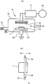
- FIG. 4 It is a conceptual diagram of an atmospheric pressure plasma processing apparatus, (a) is a whole side view, (b) is a top view which shows the relationship between a rod-shaped electrode and a board
- the C1s orbital XPS spectrum of the surface modification molding obtained in Examples 4 and 6 and Comparative Example 1 is shown.
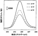
- the F1s orbital XPS spectrum of the surface modification molding obtained in Examples 4 and 6 and Comparative Example 1 is shown.
- the O1s orbital XPS spectrum of the surface modification molding obtained in Examples 4 and 6 and Comparative Example 1 is shown.
- the surface temperature of the molded body containing the organic polymer compound is at a temperature equal to or higher than (the melting point of the organic polymer compound ⁇ 120) ° C. and atmospheric pressure. It is possible to improve the surface hardness while introducing a peroxide radical to the surface of the molded body by performing a treatment with plasma.
- the surface temperature of the molded body is (the melting point of the organic polymer compound (hereinafter sometimes simply referred to as the melting point) ⁇ 120) ° C. included in the molded body. Set the temperature above. By using such a surface temperature, the mobility of the polymer of the organic polymer compound on the surface of the molded body that is the target of plasma irradiation is increased.
- the surface temperature of the molded body is more preferably (melting point ⁇ 100) ° C. or more, and further preferably (melting point ⁇ 80) ° C. or more.
- the surface temperature of the molded body is preferably set in the above range.
- the surface temperature of the molded body satisfies the requirement of (melting point ⁇ 120) ° C. or higher and preferably 20 ° C. or higher.
- the upper limit of the surface temperature of the molded body is not particularly limited, but may be, for example, (melting point + 20) ° C. or lower.
- the effect of improving the strength of the surface layer can be grasped as an index of the indentation hardness (hereinafter, simply referred to as “indentation hardness”) due to nanoindentation of the surface of the molded body.
- This indentation hardness (Hardness, unit: N / mm 2 ) can be expressed by using an average value when measured under the conditions of indentation load: 40 ⁇ N and number of measurements: 50 times.
- the peroxide radical density on the surface of the molded body modified by the production method of the present invention is 1.4 times that of the molded body that has been subjected to atmospheric pressure plasma treatment at a surface temperature of less than (melting point ⁇ 120) ° C. It can be made above, preferably 1.5 times or more, more preferably 1.8 times or more.
- the indentation hardness of the surface of the surface-modified molded body is 1.4 times or more the hardness of the surface of the molded body before the plasma treatment.
- the indentation hardness can be improved by adjusting the surface temperature of the molded body as described above and performing atmospheric pressure plasma treatment, the strength of the surface layer portion of the surface-modified molded body is improved, and a composite with the adherend is obtained.
- the bonding strength at the time can be improved.
- the indentation hardness of the surface-modified molded body is more preferably 1.5 times or more, more preferably 1.6 times or more of that before the plasma treatment. Preferably, it is 1.7 times or more, and the upper limit is not limited, but it is, for example, 2.5 times or less.
- the indentation hardness of the surface of the surface-modified molded body varies depending on the type of organic polymer compound constituting the molded body.
- the hardness of the surface of the molded body after the modification is indentation hardness can, for example, 170N / mm 2 or more, preferably 185 N / mm 2 or more, more preferably 200 N / mm 2 or more.
- the upper limit of the indentation hardness is not limited, but may be, for example, 250 N / mm 2 or less.
- the surface of the molded body opposite to the plasma irradiation surface is hardly affected by the plasma treatment (the effect of improving the hardness is smaller than that of the plasma irradiation surface).
- Various inherent properties for example, chemical resistance, weather resistance, heat resistance, electrical insulation, etc. are fully exhibited without being impaired.
- the method for producing a surface-modified molded body according to the present invention can reduce the root mean square roughness (nm rms) of the surface of the molded body before plasma treatment.
- plasma treatment improves the adhesion by roughening the surface (see, for example, Patent Document 1), but in the present invention, the surface can be modified so that the surface is rather smooth.
- the mobility of the polymer of the organic compound on the surface is increased, the crosslinking reaction between the carbon atoms occurs between the polymers, and the formation of irregularities is suppressed.
- the root mean square roughness (rms) of the surface of the modified molded body is preferably 1.5 times or less, more preferably 1.3 times or less, and still more preferably the surface before the plasma treatment. Is 1.1 times or less, and preferably 1 time or less.
- the lower limit of the ratio of the root mean square roughness of the modified molded body surface to the surface before the plasma treatment is not particularly limited, but is, for example, 0.3 times or more.
- the value of the root mean square roughness of the surface of the modified molded body varies depending on the type of organic polymer compound constituting the molded body and the surface state before the plasma treatment, but is, for example, 40 to 250 (nmrms). it can.
- Examples of the organic polymer compound constituting the molded product that can be used in the present invention include olefin resins such as fluororesin, polyethylene resin, polypropylene resin, and cycloolefin resin, polyester resins such as polyethylene terephthalate resin, and polyimide resins.
- Styrene resins such as resins, styrene resins and syndiotactic polystyrene resins, aromatic polyether ketone resins such as aromatic polyether ketone resins, polyether ether ketone resins and polyphenylene ether resins, polyacetal resins and polyphenylene sulfide resins And bismaleimide triazine resin. These may be used alone or in combination of two or more.
- a liquid crystal polymer represented by a fluororesin and a polyester, a polymer alloy or a copolymer with a polyimide resin, and the like can be given.
- the adhesive improvement is more effective, it is preferably applied to a fluororesin and an olefin resin, and a fluororesin is particularly preferable.
- fluororesin examples include polytetrafluoroethylene (PTFE, melting point: 327 ° C.), polychlorotrifluoroethylene (PCTFE, melting point: 220 ° C.), polyvinylidene fluoride (PVDF, melting point: 151 to 178 ° C.), polyvinyl fluoride.
- PTFE polytetrafluoroethylene
- PCTFE polychlorotrifluoroethylene
- PVDF polyvinylidene fluoride
- the form of the molded body that can be used in the present invention is not particularly limited as long as it is a shape that can be irradiated with plasma, and can be applied to those having various shapes and structures. Examples thereof include, but are not limited to, a square shape, a spherical shape, and a thin film shape having a surface shape such as a flat surface, a curved surface, and a bent surface.
- the molded body may be molded by various molding methods such as injection molding, melt extrusion molding, paste extrusion molding, compression molding, cutting molding, cast molding, and impregnation molding depending on the characteristics of the organic polymer compound. .
- the molded body may have a continuous structure in which a resin, for example, a normal injection molded body is dense, a porous structure, a non-woven fabric, or other structures. good.
- the surface of the molded body containing the organic polymer compound is modified by atmospheric pressure plasma.
- the conditions for the treatment with the atmospheric pressure plasma are not particularly limited as long as peroxide radicals can be introduced into the surface of the molded body. Conditions that are capable of generating atmospheric pressure plasma, which are employed in the technical field of performing surface modification of a molded body by plasma, can be appropriately employed.
- the treatment with atmospheric pressure plasma is performed. In the case where the surface temperature is increased only by the heating effect by the atmospheric pressure plasma treatment, it is preferable to perform the atmospheric pressure plasma treatment under the condition that the heating effect is obtained.
- the output power per unit area is 15 W / cm 2 or more, preferably 20 W / cm 2 or more, more preferably 25 W / cm.
- the upper limit is not particularly limited and may be, for example, 40 W / cm 2 or less.
- the pulse modulation frequency is preferably 1 to 50 kHz (preferably 5 to 30 kHz), and the pulse duty is 5 to 99% (preferably 15 to 80%, more preferably 25 to 70%). Good.
- a cylindrical or flat metal having at least one side coated with a dielectric can be used.
- the distance between the opposed electrodes depends on other conditions, but is preferably 5 mm or less, more preferably 3 mm or less, still more preferably 1.2 mm or less, and particularly preferably 1 mm from the viewpoint of plasma generation and heating. It is as follows. Although the minimum of the distance between the electrodes made to oppose is not specifically limited, For example, it is 0.5 mm or more.
- a gas used for generating plasma for example, a rare gas such as helium, argon, or neon, or a reactive gas such as oxygen, nitrogen, or hydrogen can be used. That is, it is preferable to use only a non-polymerizable gas as the gas used in the present invention.
- the polymerization reactive gas such as the monomer vapor described in Patent Document 2 complicates the plasma processing step and the apparatus used.
- the oxygen concentration is preferably 0.3% or less, more preferably 0.1% or less, still more preferably 0.01% or less, and most preferably 0.005% or less.
- the lower limit of the oxygen concentration is not particularly limited, but is usually about 0.0005%.
- these gases may use only 1 type, or 2 or more types of noble gases, or a mixed gas of 1 type or 2 types or more of noble gases and an appropriate amount of 1 type or 2 types or more of reactive gases. It may be used.
- the generation of the plasma may be performed under the above-described conditions in which the gas atmosphere is controlled using a chamber, or may be performed under a completely open atmosphere condition in which, for example, a rare gas is flowed to the electrode portion.
- FIG. 1 is a conceptual diagram of a capacitively coupled atmospheric pressure plasma processing apparatus that is an example of an atmospheric pressure plasma processing apparatus that can be used in the present invention.
- An atmospheric pressure plasma processing apparatus A shown in FIG. 1A includes a high-frequency power source 10, a matching unit 11, a chamber 12, a vacuum exhaust system 13, an electrode 14, a grounded electrode lifting mechanism 15, a scanning stage 16, and a scanning stage control unit. (Not shown).
- a sample holder 19 that holds the molded body 1 is disposed on the upper surface of the scanning stage 16 so as to face the electrode 14.
- an aluminum alloy can be used.
- the electrode 14 has a rod-like shape, for example, a structure in which the surface of an inner tube 17 made of copper is covered with an outer tube 18 of, for example, aluminum oxide (Al 2 O 3 ). It can be used.
- the surface modification method of the molded body using the atmospheric pressure plasma processing apparatus A shown in FIG. 1 is as follows. First, the molded body is washed with an organic solvent such as acetone or water such as ultrapure water if necessary, and then a sheet-shaped molded body 1 is formed on the upper surface side of the sample holder 19 in the chamber 12 as shown in FIG. After that, the air in the chamber 12 is sucked from the vacuum exhaust system 13 by a suction device (not shown) to reduce the pressure, and a gas for generating plasma is supplied into the chamber (see the arrow in FIG. 1A). The inside of 12 is made atmospheric pressure. The atmospheric pressure does not have to be strictly 1013 hPa, and may be in the range of 700 to 1300 hPa.
- the scanning stage controller adjusts the height of the electrode lifting mechanism 15 (vertical direction in FIG. 1), and moves the scanning stage 16 to a desired position.
- the distance between the electrode 14 and the surface (upper surface) of the molded body 1 can be adjusted.
- the distance between the electrode 14 and the surface of the molded body 1 is preferably 5 mm or less, and more preferably 1.2 mm or less.
- the distance is particularly preferably 1.0 mm or less.
- the distance between the electrode 14 and the surface of the molded body 1 should be larger than zero.
- a desired portion of the surface of the molded body is irradiated with plasma.
- the moving speed of the scanning stage is preferably 1 to 3 mm / second, but the present invention is not limited to such an example.
- the plasma irradiation time to the molded body 1 can be adjusted, for example, by adjusting the moving speed or reciprocating the scanning stage 16 a desired number of times.
- plasma is generated between the electrode 14 and the sample holder 19, and a desired range on the surface of the molded body 1 is obtained. Irradiate plasma.
- a high frequency power source having a frequency of applied voltage or an output power density as described above is used.
- an alumina-coated copper electrode and an aluminum alloy sample holder are used, so that glow under a dielectric barrier discharge condition is achieved. Discharging can be realized. Therefore, peroxide radicals can be generated stably on the surface of the molded body.
- peroxide radicals induced the formation of dangling bonds by defluorination on the surface of the PTFE sheet by radicals, electrons, ions, etc. contained in the plasma, and the air remaining in the chamber or cleaned after the plasma treatment. It is performed by reacting with water components in the air by exposing to fresh air.
- hydrophilic functional groups such as a hydroxyl group and a carbonyl group can be spontaneously formed in the dangling bond.
- the intensity of the plasma applied to the surface of the molded body can be appropriately adjusted according to the various parameters of the above-described high-frequency power source, the distance between the electrode 14 and the surface of the molded body, and the irradiation time. Therefore, when the surface of the molded body is brought into a specific range by natural temperature rise by plasma treatment, these conditions may be adjusted according to the characteristics of the organic polymer compound constituting the molded body.
- the above preferable conditions for generating atmospheric plasma are particularly effective when the molded body has a sheet shape made of PTFE.
- the integrated irradiation time for the molded body surface is adjusted by adjusting the integrated irradiation time for the molded body surface according to the output power density.
- the frequency of the applied voltage is 5 to 30 MHz
- the distance between the electrode 14 and the surface of the molded body is 0.5 to 2.0 mm
- the output power density is 15 to 30 W / cm 2
- the integrated irradiation on the surface of the molded body The time is preferably 50 seconds to 3300 seconds, more preferably 250 seconds to 3300 seconds, and particularly preferably 550 seconds to 2400 seconds.
- the surface temperature of the PTFE sheet-shaped molded body is preferably 210 to 327 ° C.
- the irradiation time is preferably 600 to 1200 seconds.
- the plasma irradiation time means an integrated time during which the surface of the molded body is irradiated with plasma, and it is sufficient that the surface temperature of the molded body is at least (melting point ⁇ 120) ° C. at least part of the plasma irradiation time.
- the surface temperature of the molded body may be (melting point ⁇ 120) ° C. or more in 1/2 or more (preferably 2/3 or more) of the plasma irradiation time.
- the surface temperature of the molded body within the above range, the mobility of PTFE molecules on the surface of the molded body is improved, and the carbon atom of the carbon-fluorine bond of a certain PTFE molecule cut by plasma
- the probability that a carbon-carbon bond is formed by binding to a carbon atom of another PTFE molecule generated in the same manner can be remarkably improved, and the surface hardness can be improved.
- the heating means for heating the molded object 1 can be provided separately.
- a circulation device including a heating device that heats the gas in the chamber and a stirring blade that circulates the heated gas in the chamber 12 is provided in the chamber 12.
- a heat ray irradiation device for irradiating heat rays such as infrared rays may be disposed in the vicinity of the electrode 14, or the molded body 1 may be disposed on the lower surface side.
- a heating means may be arranged in the sample holder 19 or a combination thereof.
- the intensity of the plasma can be reduced as compared with the case where only the heating effect by the plasma treatment is performed, and the output power per unit area may be less than 15 W / cm 2. (However, it is preferably 5 W / cm 2 or more).
- the heating temperature by the heating means may be appropriately set and controlled in consideration of the characteristics of the organic compound constituting the molded body, the shape of the molded body, the heating effect by plasma treatment, and the like. Moreover, it is preferable to pre-heat the molded body before operating the high-frequency power supply 10 so that a desired temperature is reached during plasma irradiation.
- the surface temperature of the molded body during the plasma treatment can be measured by using, for example, a temperature measurement seal or a radiation thermometer.
- the adherend is directly bonded to the surface of the surface-modified molded body by bringing the adherend into contact with the modified surface (modified surface). can do.
- the adherend has a reactive functional group
- the peroxide radical introduced on the surface of the surface-modified molded body and the reactive functional group of the adherend act to intervene both.
- the surface-modified molded body and the adherend can be directly joined.
- the adherend having a reactive functional group that can be used in the present invention reacts with peroxide radicals introduced into the surface-modified molded article, and the constituent material itself of the adherend It is preferable that the reactivity of the reactive functional group is substantially lost by this reaction. That is, it is preferable to use the reactive functional group necessarily contained in the constituent material of the adherend for bonding with the surface-modified molded body. Further, such a functional group may be introduced in advance into the constituent material of the adherend while considering the function of the adherend. Examples of the material constituting the adherend include rubber, thermosetting resin, and predetermined silver-containing composition.
- Examples of rubber that can be used in the present invention include vulcanized rubber, thermosetting resin elastomer, and thermoplastic elastomer.
- Examples of such rubbers include nitrile rubbers such as butyl rubber, isoprene rubber, butadiene rubber, styrene butadiene rubber, natural rubber, chloroprene rubber, and acrylonitrile butadiene rubber, hydrogenated nitrile rubber, norbornene rubber, and ethylene propylene rubber.
- EPDM rubber Ethylene-propylene-diene rubber
- acrylic rubber ethylene acrylate rubber
- fluorine rubber chlorosulfonated polyethylene rubber
- epichlorohydrin rubber silicone rubber
- urethane rubber polysulfide rubber
- examples thereof include phosphanzene rubber and 1,2-polybutadiene.
- One of these may be used alone, or two or more of these may be used in combination.
- butyl rubber and EPDM rubber are preferred.
- reactive functional groups such as a halogen and a thiol group, from a viewpoint of joining with the surface modification molded object mentioned above.
- Butyl rubber is known to have excellent gas permeation resistance and water vapor permeation resistance, and is suitable for applications such as stopcocks that require such characteristics.
- the butyl rubber include isobutylene-isoprene copolymer rubber, halogenated isobutylene-isoprene copolymer rubber (hereinafter referred to as “halogenated butyl rubber”), and modified products thereof.
- the modified product include a brominated product of a copolymer of isobutylene and p-methylstyrene.
- halogenated butyl rubber is preferable because of easy crosslinking, and chlorinated butyl rubber or brominated butyl rubber is more preferable.
- EPDM rubber is known to be excellent in processability and is suitable for various molded products requiring such characteristics.
- diene monomer in the EPDM rubber include dicyclopentadiene, methylene norbornene, ethylidene norbornene, 1,4-hexadiene, and cyclooctadiene.
- butyl rubber and EPDM rubber are used in combination, a combination of halogenated butyl rubber and EPDM rubber is preferable. Both have good compatibility and can be made into a rubber excellent in gas permeability resistance, water vapor resistance, and processability.
- a crosslinking agent is added to the rubber described above depending on the type of polymer as a main ingredient, and the polymer is crosslinked by heating or the like. Therefore, in the present invention, when a composite is formed using rubber as an adherend, a crosslinking agent usually selected according to the type of rubber as the main agent is used as the peroxide radical on the surface of the surface-modified molded body. It is preferable to act. However, even if it is not generally used for the main polymer, a cross-linking agent that can be similarly cross-linked is added to the extent that it does not impair the function of the rubber to improve the bondability with the surface-modified molded body. You may let them.
- crosslinking agent when there exists a joining effect by a crosslinking agent, a reactive functional group does not necessarily need to be contained in the polymer of a main ingredient.
- crosslinking agents include peroxide crosslinking agents such as sulfur and dicumyl peroxide, quinoid crosslinking agents such as p-quinonedioxime and p, p′-dibenzoylquinonedioxime, and low molecular weight compounds.
- Resin-based crosslinking agents such as alkylphenol resins, amine-based crosslinking agents such as diamine compounds (such as hexamethylenediamine carbamate), and triazine thiol-based crosslinking agents such as 2-di-n-butylamino-4,6-dimercapto-s-triazine Polyol-based crosslinking agents, metal oxide-based crosslinking agents, and the like.
- amine-based crosslinking agents such as diamine compounds (such as hexamethylenediamine carbamate)
- triazine thiol-based crosslinking agents such as 2-di-n-butylamino-4,6-dimercapto-s-triazine
- Polyol-based crosslinking agents such as butyl rubber, it is preferable to use a triazine thiol crosslinking agent from the viewpoint of improving the bonding strength with the surface-modified molded body.
- thermosetting resin examples include, but are not limited to, epoxy resin, phenol resin, polyurethane, polyimide, and the like.
- a thermosetting resin is generally one that cures by crosslinking monomers or oligomers by heating, and contains a compound having a reactive functional group before curing, and the reactive functional group substantially disappears by crosslinking. It becomes a cured product. Therefore, when the thermosetting resin is cured, the reactive functional group and the peroxide radical on the surface of the surface-modified molded body act to bond the surface-modified molded body and the cured product of the thermosetting resin to form a composite. Is obtained.
- the silver-containing composition examples include a composition containing a silver compound (A) represented by the above formula (1) and an amine compound (B) represented by the above formula (2) at a specific ratio.
- This silver-containing composition is suitably used as a raw material for a metal film of a dielectric substrate with a metal film used as, for example, a high-frequency device used in a mobile phone or a communication circuit.
- Silver compound (A) is acetone acetone dicarboxylate, and its form is usually powder.
- the silver compound (A) is a substance that has a high viscosity when diluted with a solvent and is difficult to pattern such as printing.
- the viscosity can be set low even in a composition having a high silver content.
- the silver compound (A) has a high decomposition temperature as a simple substance, and it takes a long time to produce metallic silver by firing at 150 ° C. or less (particularly less than 150 ° C.).
- metallic silver can be produced by low-temperature and short-time firing at 150 ° C. or less (particularly less than 150 ° C.).
- the storage stability (determined by the formation of silver particle precipitates) is remarkably improved as compared with the case of using other silver carboxylates.
- the silver compound (A) content is 10-50% by mass and the amine compound (B) content is 100% by mass of the silver compound (A) and the amine compound (B). Is 50 to 90% by mass.
- the content ratio of the silver compound (A) is preferably 20 to 40% by mass, and the content ratio of the amine compound (B) is preferably 60 to 80% by mass.
- the silver compound (A) can be contained in an amount of 50 to 70% by mass.
- the amine compound (B) content is less than 50% by mass, the solubility of the silver compound (A) May be significantly reduced.
- the method for producing the silver compound (A), which is silver acetonedicarboxylate used in the present invention is not limited in any way, and is described in known literature, for example, “Jornal furfite Chemie. Band 312 (1970) pp. 240-244”. A method is mentioned.
- silver acetone dicarboxylate is produced using a basic substance, it is desirable to use an organic base in order to avoid contamination with metal ions.
- the amine compound (B) used in the present invention is a compound represented by the above formula (2), wherein R 1 is a hydrogen atom,-(CY 2 ) a -CH 3 or-((CH 2 ) b —O—CHZ) c —CH 3 , wherein R 2 represents a phenyl group, — (CY 2 ) d —CH 3 or — ((CH 2 ) e —O—CHZ) f —CH 3 .
- Y represents a hydrogen atom or — (CH 2 ) g —CH 3
- Z represents a hydrogen atom or — (CH 2 ) h —CH 3 .
- a is an integer from 0 to 8
- b is an integer from 1 to 4
- c is an integer from 1 to 3
- d is an integer from 1 to 8
- e is an integer from 1 to 4
- f is an integer from 1 to 3
- g is An integer of 0 to 3 (especially an integer of 1 to 3)
- h is an integer of 0 to 2 (especially an integer of 1 to 2).
- Examples of the amine compound (B) include ethylamine, 1-propylamine, 1-butylamine, 1-pentylamine, 1-hexylamine, 1-heptylamine, 1-octylamine, 2-ethylhexylamine, isopropylamine, isobutyl.
- R 1 of the amine compound (B) is a hydrogen atom
- Y and Z are each preferably a hydrogen atom or a methyl group
- a is preferably an integer of 2 to 6
- b is an integer of 1 to 3
- c is preferably 1 or 2.
- R 2 is — (CY 2 ) d —CH 3 or — ((CH 2 ) e —O—CHZ) f —CH 3
- Y and Z are hydrogen atoms
- d is an integer of 1 to 6
- E is preferably an integer of 1 to 3
- f is preferably an integer of 1 to 2.
- an amine compound (B) having a boiling point of less than 130 ° C.
- Examples of the amine compound (B) satisfying these include 1-propylamine, 1-butylamine, 1-pentylamine, 1-hexylamine, 1-heptylamine, 1-octylamine, isopropylamine, isobutylamine, Pentylamine, 3-methoxypropylamine, 2-ethoxypropylamine, 3-isopropoxypropylamine, diisopropylamine, and dibutylamine are preferably used.
- a solvent is appropriately added in addition to the silver compound (A) and the amine compound (B) for the purpose of improving the coating property on the surface-modified molded body and adjusting the viscosity. be able to.
- the amount of the solvent used is preferably 20 to 80% by mass with respect to 100% by mass in total of the silver compound (A), the amine compound (B) and the solvent. Furthermore, 40 to 60% by mass is more preferable with respect to 100% by mass in total of the silver compound (A), the amine compound (B) and the solvent. If the amount of solvent exceeds 80% by mass, a uniform silver film may not be obtained due to a decrease in silver content.
- the type of the solvent is not particularly limited, but is preferably a solvent that can be easily removed during the production of the silver film.
- the solvent include methanol, ethanol, 1-propanol, 2-propanol, 1-butanol, 2-butanol, tert-butanol, 1-pentanol, 2-pentanol, 3-pentanol, and tert-amyl.
- Alcohols such as alcohol, ethylene glycol, butoxyethanol, methoxyethanol, ethoxyethanol, propylene glycol, propylene glycol monomethyl ether, propylene glycol monopropyl ether, propylene glycol monobutyl ether and dipropylene glycol monomethyl ether, acetoxymethoxypropane, phenylglycidyl ether And ethers such as ethylene glycol glycidyl, acetone, methyl ethyl ketone, methyl isobutyl ketone, etc.
- Ketones acetonitrile, propionitrile, nitriles such as butyronitrile and isobutyronitrile, sulfoxides such as DMSO, water and 1-methyl-2-pyrrolidone, and the like. These solvents can be used alone or in combination depending on the application.
- ethanol 1-propanol, 2-propanol, 1-butanol, 2-butanol, 1-pentanol, tert-amyl alcohol, ethylene glycol , Butoxyethanol, methoxyethanol, ethoxyethanol, propylene glycol, propylene glycol monomethyl ether, propylene glycol monopropyl ether, propylene glycol monobutyl ether and dipropylene glycol monomethyl ether, methyl ethyl ketone and methyl isobutyl ketone, acetonitrile, propionitrile, butyronitrile, iso One or more of butyronitrile is preferably mentioned.
- the solvent not only is it added to the mixture of the silver compound (A) and the amine compound (B), but also the silver compound (A) is added to the mixture of the amine compound (B) and the solvent,
- the silver compound (A) is added to the mixture of the amine compound (B) and the solvent.
- the order to add such as adding an amine compound (B) to the mixture of (A) and a solvent.
- the leveling property for the surface-modified molded article is adjusted with hydrocarbon, acetylene alcohol, silicone oil, etc., or the surface is added with a coupling agent such as a silane coupling agent.
- a coupling agent such as a silane coupling agent.
- a silver colloid in which the composition is preheated or a generally known reducing agent is allowed to act to form silver clusters and nanoparticles. It can also be a dispersion.
- a borohydride compound, a tertiary amine, a thiol compound, a phosphorus compound, ascorbic acid, a quinone, a phenol or the like can be added to such an extent that conductivity and flatness are not lost.
- the surface of the surface-modified molded body and the adherend are brought into contact with each other, and the surface of the surface-modified molded body is adhered to the adherend.
- the surface of the adherend is cured by heating. It is preferable to include a step of directly joining the surface of the modified molded body.
- the conditions for curing by heating may be appropriately determined depending on the material constituting the adherend, and can be selected from the range of 20 to 350 ° C., for example.
- a kneaded product of unvulcanized rubber is prepared in advance and heated for a predetermined time in a state where it is in contact with the modified surface of the surface-modified molded body. Then, pressure is applied to crosslink the polymer to cure the unvulcanized rubber, and the peroxide radical on the surface of the surface-modified molded body and the reactive functional group of the rubber are allowed to act to directly bond both. As a result, a vulcanized rubber (a composite of the surface-modified molded body and the vulcanized rubber) having a portion coated with the surface-modified molded body is obtained.
- the conditions at this time are as follows.
- the surface-modified molded body is in the form of a sheet made of a fluororesin, a heating temperature of 140 to 200 ° C., a pressure of 10 to 20 MPa, and a heating and pressing treatment are performed for 10 to 40 minutes.
- a heating temperature of 140 to 200 ° C., a pressure of 10 to 20 MPa, and a heating and pressing treatment are performed for 10 to 40 minutes.
- what is necessary is just to laminate
- an adherend is formed so as to have a predetermined shape and the surface is covered with a sheet-like surface-modified molded body, the surface-modified molded body is placed in advance in the mold cavity and adhered. Transfer molding or the like for injecting the body into the cavity may be performed.
- thermosetting resin for example, a liquid containing a monomer, oligomer, polymer, cross-linking agent, etc. is applied to the modified surface of the surface-modified molded body and heated, or these The powder, paste, etc. containing the resin are brought into contact with the modified surface, and heated (for example, 20 to 350 ° C.) and pressurized to cure the thermosetting resin and to form peroxide radicals on the surface of the surface-modified molded body.
- a thermosetting resin or a reactive functional group of a cross-linking agent is allowed to act to bond both directly. Thereby, the composite_body
- the material constituting the adherend is the above-described silver-containing composition
- the above-mentioned silver-containing composition is prepared and applied to the modified surface of the surface-modified molded body to form an ultrathin film.
- the silver-containing composition is cured to form a silver thin film layer, and the peroxide radical on the surface of the surface-modified molded body and the silver-containing composition are allowed to act to directly bond them.
- a surface-modified molded body composite of a surface-modified molded body and a silver thin film having a silver thin film layer formed on the surface is obtained.
- the silver-containing composition can be applied by spin coating or printing.
- the application method include, but are not limited to, a spray spray method, an ink jet printing method, an offset printing method, a gravure offset printing method, a dipping method, and a doctor blade coating method.
- the heating temperature at the time of heating after coating the silver-containing composition is not particularly limited as long as it is room temperature or higher. However, in consideration of productivity, heating at 80 ° C. or higher is preferable for firing in a short time.
- heating at 80 ° C. or higher is preferable for firing in a short time.
- the silver compound (A) and the amine compound (B) are used at a specific ratio, so that the silver concentration in the composition can be increased and is less than 150 ° C. in the absence of a catalyst.
- a metallic silver film can be obtained quickly at a low temperature. Therefore, the metal silver film can be formed in a short time because the metal silver film can be formed at a low temperature, and the metal silver film can be formed in a further short time at a high temperature of 150 ° C. or higher, thereby improving productivity. Can be expected.
- the material constituting the molded body is a fluororesin, particularly PTFE, it has high adhesion on the surface of the molded body (dielectric substrate) made of a fluororesin having a high signal propagation speed and relatively low power consumption.
- a dielectric base material (composite) with a metal film on which a metal film made of a silver thin film is formed can be provided more easily and at a lower cost than conventional ones.
- the above-mentioned silver-containing composition when used as a material constituting the adherend, a grafting agent is reacted with the surface of the surface-modified molded body into which peroxide radicals are introduced to coordinate with silver ions.
- the above-mentioned silver-containing composition After performing the step of fixing the functional group to be bonded, the above-mentioned silver-containing composition is applied to the surface of the surface-modified molded body on which the functional group coordinated with the silver ion is fixed, and heated and cured.
- the composite may be formed by performing a step of forming a silver thin film layer.
- the functional group that coordinates with the silver ions of the silver-containing composition is fixed by the grafting agent from the peroxide radical formed on the surface of the molded body by atmospheric pressure plasma.
- the adhesion strength of the silver thin film is further improved.
- the peroxide radical is formed by atmospheric pressure plasma treatment.
- An ultra-thin film is produced by applying a grafting agent to the surface of the surface-modified molded body introduced on the surface by a liquid phase method such as a spin coating method.
- the radical radical introduced on the surface of the surface-modified molded body is used as a reaction point to spontaneously form a covalent bond with the grafting agent, so that the grafting agent becomes dense from the surface-modified molded body surface. To be grafted.
- a method of applying the grafting agent in addition to the spin coating method, for example, spray spraying method, inkjet printing method, offset printing method, gravure offset printing method, dipping method, doctor blade coating method and the like can be mentioned. It is not limited to.
- a compound or polymer having a functional group such as an ether group, an ester group, a phosphate group, a urea group, a thiol group, a thienyl group, or a thiourea group is preferred, and an atomic group containing at least one of N, P, and S More preferred is a complexing compound or complexing polymer having a functional group coordinated with silver ions.
- preferable complexing compounds include, for example, vinylamine, acrylamide, acrylicamine, acrylonitrile, vinylaniline, vinylisocyanate, vinylpyrrole, vinylpyrrolidone, vinyltriazine, vinylphosphonic acid, vinylphosphoric acid, vinylthiol, vinylthiophene, vinyl. Although sulfonic acid etc. are mentioned, it is not limited to these.
- Preferred complexing polymers include, for example, polymers of the complexing compounds such as polyvinylamine, polyacrylamide, polyacrylamine, polyacrylonitrile, polyvinylaniline, polyvinyl isocyanate, polyvinyl pyrrole, polyvinyl pyrrolidone, polyvinyl triazine, polyvinyl Examples thereof include, but are not limited to, phosphonic acid, polyvinyl phosphoric acid, polyvinyl thiol, polyvinyl thiophene and polyvinyl sulfonic acid.
- a step of forming a silver thin film layer by applying the above-mentioned silver-containing composition to the surface of the surface-modified molded body on which the functional group that coordinates with silver ions is fixed, and heating and curing is performed.
- This step can be performed in the same manner as already described. That is, the above silver-containing composition is applied by a liquid phase method such as spin coating to produce an ultrathin film, and then the applied silver-containing composition thin film is heated and cured to form a silver thin film layer. Is done.
- the composite obtained as described above is suitable as a stopcock or the like that comes into contact with a drug in a container that encloses the drug when the material that forms the molded body is a fluororesin and the component material of the adherend is rubber, for example. It is.
- the material constituting the molded body is a fluororesin and the constituent material of the adherend is a specific silver-containing composition, it is suitable as a high-frequency printed circuit board material.
- Examples 1 to 6, Reference Example, Comparative Example 1 The surface of the PTFE sheet-shaped molded body was modified by atmospheric pressure plasma using a plasma generator (product name: K2X02L023, manufactured by Meisho Kiko Co., Ltd.) having the configuration shown in FIG.
- a plasma generator product name: K2X02L023, manufactured by Meisho Kiko Co., Ltd.
- a PTFE sheet (Nitoflon No. 900UL) cut to a thickness of 0.2 mm by Nitto Denko Corporation was cut into a certain size (width: 30 mm, length: 30 mm).
- the molded body was ultrasonically cleaned in acetone for 1 minute, and then ultrasonically cleaned in ultrapure water for 1 minute.
- nitrogen gas (purity: 99% or more) was sprayed and removed from the ultrapure water adhering to the molded body by an air gun.
- the high frequency power source of the plasma generator one having an applied voltage frequency of 13.56 MHz was used.
- the electrode an electrode having a structure in which a copper tube having an inner diameter of 1.8 mm, an outer diameter of 3 mm, and a length of 165 mm was covered with an alumina tube having an outer diameter of 5 mm, a thickness of 1 mm, and a length of 100 mm was used.
- a sample holder made of an aluminum alloy and having a width of 20 mm and a length of 120 mm was used.
- the molded body was placed on the upper surface of the sample holder, and the distance between the molded body surface and the electrode was set to 1.0 mm.
- the chamber was sealed and reduced in pressure to 10 Pa with a rotary pump, and then helium gas was introduced until atmospheric pressure (1013 hPa) was reached.
- the high-frequency power source is set so as to have the output power density shown in Table 1, and the scanning stage is moved at a speed of 2 mm / second and the length that the electrode passes is the entire length in the length direction of the molded body (that is, 30 mm) was set to move. Thereafter, the high frequency power source was activated, the scanning stage was moved, and plasma irradiation was performed under the conditions shown in Table 1.
- the total irradiation time was adjusted by the number of reciprocations of the scanning stage. Further, the surface of the molded body at the time of plasma treatment was measured with a temperature measurement seal (Nippon Giken Kogyo, Thermolabel). The measurement results are shown in Table 1.
- the reference example means a PTFE sheet itself that has not been subjected to plasma treatment.
- thermolabel manufactured by NOF CORPORATION, 3E-110, 3E-150, 3E-190, 3E-230, thermo In loop G-1
- the highest temperatures at which discoloration was confirmed were 240 ° C., 240 ° C., 330 ° C., 210 ° C., and 110 ° C., respectively.
- the acquisition of temperature data was unsatisfactory, but Example 3 is an example in which the plasma irradiation time was longer than that of Example 2 with the same power as that of Example 2.
- the surface temperature of Example 3 is considered to be not less than the value of Example 2.
- Example 5 is an example in which the same electric power as in Example 4 was used and the plasma irradiation time was longer than that in Example 4.
- the surface temperature of Example 5 seems to be equal to or higher than the value of Example 4. .
- X-ray photoelectron spectroscopy measurement Chemical structure analysis by X-ray photoelectron spectroscopy (XPS) was performed on the modified surfaces of the surface-modified molded bodies obtained in Examples 4 and 6 and Comparative Example 1 using PHI Quantum 2000 manufactured by ULVAC-PHI. .
- the excitation X-ray source of the apparatus was Al—K ⁇ ray, and the excitation X-ray output was 25 W.
- the results of the C1s, F1s, and O1s spectra are shown in FIGS. Peaks derived from -CF2- bonds, that is, peaks near 292 eV shown in the C1s spectrum of FIG. 2 and peaks near 689 eV shown in the F1s spectrum of FIG.
- the atmospheric pressure plasma treatment is performed under the condition that the output voltage is increased, that is, the surface temperature is increased, the carbon-fluorine bond on the surface is broken by the atmospheric pressure plasma, and peroxide radicals and the like are present on the carbon. It is considered that a carbon-carbon bond between the polymers of PTFE is generated along with the bonding. Moreover, the above-described indentation hardness is improved because of the carbon-carbon bond between the PTFE polymers.
- ⁇ Measurement of root mean square roughness (rms)> The root mean square roughness (nm rms) of the modified surfaces of the surface-modified molded bodies obtained in Examples and Comparative Examples was measured using OLS3100 manufactured by Olympus. In addition, as a reference example (control), the root mean square roughness of the surface of a molded body not treated with atmospheric pressure plasma was measured. Table 3 shows the measurement results.
- the surface modification method using atmospheric pressure plasma of the present invention is different from conventional general plasma treatment.
- a composite with an adherend was produced as follows. did. Halogenated butyl rubber (ExxonMobil Co., Ltd., Butyl 1066) 100 parts by weight, 2-di-n-butylamino-4,6-dimercapto-s-triazine (Sankyo Kasei Co., Ltd., Disnet (registered trademark)) as a crosslinking agent 3 parts by weight, 3 parts by weight of paraffinic process oil (Idemitsu Kosan Co., Ltd., Diana Process Oil PW380) as a plasticizer, and 1 part by weight of magnesium oxide (Kyowa Chemical Industry Co., Ltd., Kyowa Mag 150 (registered trademark)) as an acid acceptor Kneading, producing a rubber sheet with a thickness of 2 mm by a rubber roll machine (manufactured by Nippon Roll Manufacturing Co.
- Halogenated butyl rubber ExxonMobil Co., Ltd., Butyl 1066
- the reactive functional group at this time is a halogen of butyl rubber and / or a thiol group of a crosslinking agent.
- This unvulcanized rubber sheet and the surface-modified part of the surface-modified PTFE sheet are brought into contact with each other, laminated, and compressed using a compression molding machine (Kanto Metal Industries, NF-50) at a temperature of 180 ° C. and a pressure of 10 MPa. By heating and pressurizing for 10 minutes, the unvulcanized rubber was vulcanized and cured to obtain a composite in which the vulcanized rubber was directly bonded to the surface of the surface-modified PTFE sheet. The following peel test was performed using the obtained composite.
- the vulcanized rubber sheet (thickness: 2 mm) was cut so that the joining range was 20 mm ⁇ 30 mm and the unjoined range (grasping margin) was 10 mm ⁇ 30 mm.
- the size of the PTFE sheet was 30 mm ⁇ 30 mm and the thickness was 0.2 mm.
- the joining range and the non-joining range are the same as those of the vulcanized rubber sheet.
- a precision universal testing machine Shiadzu Corporation, AUTOGRAPH AG-1000D
- the gripping margin was sandwiched between chucks, the PTFE sheet and the vulcanized rubber sheet were pulled in the direction of 180 degrees, and a T-peel test was performed.
- the load cell was 1 kN and the tensile speed was 10 mm / min.
- Table 4 The value is the maximum value during the test period.
- Example 4 ⁇ Long-term storage test> The surface-modified molded body of Example 4 was stored in a room at a temperature of 23 ° C. for 33 days. After storage, a composite was prepared in the same manner as in Example 4, and the above “peel test” was performed. The results are also shown in Table 4.
- the indentation hardness of the PTFE sheet is improved by an increase in carbon-carbon bonds (crosslinking effect) between the PTFE polymers on the surface layer.
- the improvement in the strength of the PTFE of the surface layer it is considered that the surface layer was prevented from being broken and the peel strength was dramatically improved.
- the above-described surface-modified molded product of Example 4 was stored in a room at a temperature of 23 ° C. for 6 months.
- Example 7 Using the surface-modified molded body (surface-modified PTFE sheet) obtained in Example 4, a composite with an adherend (silver-containing composition) was produced as follows.
- thermogravimetric analyzer manufactured by SII Nanotechnology Inc.
- the analysis conditions were a heating rate of 10 ° C./min and a measurement atmosphere in the air.
- the thermal decomposition temperature was 175 ° C.
- the residue after thermogravimetric analysis was 59.7%, which was in agreement with the theoretical residual rate (59.4%).
- IPA isopropyl alcohol
- ⁇ Adhesion strength test> The adhesion strength between the silver thin film and the PTFE sheet in the obtained composite was evaluated by a 90 ° peel test based on JIS K6854-1.
- a tensile tester As a tensile tester, a digital force gauge (ZP-200N) and a motorized stand (MX-500N) manufactured by Imada Manufacturing Co., Ltd. were used. The end of the PTFE sheet was pinched with a clip, and a tensile test was conducted at 1 mm / second. In this example, an adhesion strength of 1.26 N / mm was obtained.
- Example 8 The surface modification PTFE sheet obtained in Example 4 was subjected to the surface modification in the same manner as in Example 7 except that the following grafting treatment was performed and then a silver-containing ink solution was applied and heat treatment was performed. A composite in which a metal film made of a silver thin film was formed on the surface of the porous PTFE sheet was obtained. With respect to the obtained composite, the adhesion strength between the silver thin film and the PTFE sheet was measured in the same manner as in Example 7. As a result, an adhesion strength of 1.63 N / mm was obtained.
- a grafting agent As a grafting agent, an aminoethylated acrylic polymer solution (Polyment (registered trademark), NK-100PM, manufactured by Nippon Shokubai Co., Ltd.) diluted to 10 wt% with ultrapure water was used.
- the surface grafting in this example was performed by immersing the surface-modified molded product of Example 4 in an aminoethylated acrylic polymer for 10 seconds.
- the surface grafted molding was put into a beaker containing ultrapure water and subjected to ultrasonic cleaning for 1 minute. Nitrogen gas (purity: 99% or more) was sprayed onto the molded body after ultrasonic cleaning with an air gun to scatter and remove ultrapure water.
- the adhesion strength is further improved when the grafting treatment is performed.
- the printed circuit board material is required to have an adhesion strength of 0.65 N / mm or more. According to the present invention, a practical printed circuit board material can be provided simply and at low cost.
- Example 9 Using the same PTFE sheet as used in Examples 1 to 6, the output power was 25 W (8.3 W / cm 2 ), the plasma irradiation time was 1200 seconds, and the surface of the PTFE sheet was heated using a halogen heater. The plasma treatment was performed. The surface temperature of the PTFE sheet was measured by using a combination of a digital radiation temperature sensor, FT-50A, FT-H40K, and KZ-U3 #, manufactured by Keyence Corporation. The maximum temperature of the PTFE surface was 265 ° C. It was. The other plasma processing conditions are the same as the plasma processing conditions in Examples 1 to 6.
- a composite was prepared by directly bonding this PTFE sheet to butyl rubber in the same manner as in Examples 1 to 6, and a peel test was performed in the same manner as in Examples 1 to 6.
- the peel strength was 2.1 N / mm, and the butyl rubber was broken during the measurement.
- the peel strength of 2.0 N / mm or more means that the rubber is broken rather than the interface between the PTFE sheet and the rubber.
- Example 10 As a compact, ETFE (manufactured by Daikin Industries, Ltd., NEOFLON EF, melting point 254 ° C.) is used, the output power is 40 W (13.3 W / cm 2 ), the plasma irradiation time is 600 seconds, Plasma treatment was performed.
- the surface temperature of the ETFE sheet was measured in the same manner as in Example 9, the maximum temperature of the ETFE surface was 140 ° C.
- a composite was prepared by directly bonding this ETFE sheet to butyl rubber in the same manner as in Examples 1 to 6, and a peel test was conducted in the same manner as in Examples 1 to 6. As a result, the peel strength was 2.1 N / mm, and the butyl rubber was broken during the measurement.
- Example 11 Plasma processing was performed using FEP (manufactured by Daikin Industries, Ltd., NEOFLON NF, melting point 270 ° C.) as the molded body, output power of 50 W (16.6 W / cm 2 ), and plasma irradiation time of 600 seconds.
- FEP manufactured by Daikin Industries, Ltd., NEOFLON NF, melting point 270 ° C.
- the maximum temperature of the FEP sheet was 160 ° C.
- a composite was prepared by directly bonding this FEP sheet to butyl rubber in the same manner as in Examples 1 to 6, and a peel test was conducted in the same manner as in Examples 1 to 6. As a result, the peel strength was 2.9 N / mm, and the butyl rubber was broken during the measurement.
- Example 12 Plasma processing was performed using a 0.1 mm thick PFA (Neolon AF-0100, manufactured by Daikin Industries, Ltd.) as the molded body, an output power of 65 W (21.7 W / cm 2 ), and a plasma irradiation time of 300 seconds. Went.
- the surface temperature of the PFA sheet was measured in the same manner as in Example 9, the maximum temperature of the PFA surface was 250 ° C.
- a composite was prepared by directly bonding this PFA sheet to butyl rubber in the same manner as in Examples 1 to 6, and a peel test was conducted in the same manner as in Examples 1 to 6. As a result, the peel strength was 2.3 N / mm, and the butyl rubber was broken during the measurement. In Examples 9 to 12, although the rubber was ruptured, the peel strength (actually, the rupture strength of the rubber) was slightly different, but this was due to variations in the strength of the rubber.
- Example 13 A silver-containing ink solution produced in the same manner as in Example 7 was applied by spin coating to a PFA sheet that had been subjected to the same plasma treatment as in Example 12. The spin coating was performed under the conditions of a rotation speed of 2000 rpm and a rotation time of 10 seconds. The silver-containing ink was cured by heat-treating the PFA sheet coated with the silver-containing ink under the conditions of a heating temperature of 120 ° C. and a heating time of 10 minutes. Thereby, the composite_body
- Example 14 Of the plasma treatment conditions in Example 1, the pressure reduction by the rotary pump is 500 Pa, the output power is 25 W (8.3 W / cm 2 ), the plasma irradiation time is 1200 seconds, and the surface of the PTFE sheet is heated using a halogen heater. Then, plasma treatment was performed in the same manner as in Example 1 except that the maximum temperature of the PTFE surface was 245 ° C. The measurement of the surface temperature of the PTFE sheet was the same as in Example 9. A composite was prepared by directly bonding this PTFE sheet to butyl rubber in the same manner as in Examples 1 to 6, and a peel test was performed in the same manner as in Examples 1 to 6. As a result, the peel strength was 1.2 N / mm.
Abstract
L'objectif de la présente invention est de pourvoir à : un procédé de fabrication d'un article moulé à surface modifiée, grâce à quoi une résistance de surface d'un article moulé peut être améliorée et l'article moulé peut être lié sans l'utilisation d'un adhésif lorsqu'un article moulé comprenant un composé polymère organique ayant une faible adhérence, telle qu'une résine fluorée, par exemple, est lié à une partie adhérée, et moyennant quoi un appareil ou une étape de traitement dans un traitement par plasma à la pression atmosphérique ne devient pas complexe ; et un procédé de fabrication d'un composite de l'article moulé à surface modifiée et d'une partie adhérée. La présente invention concerne un procédé de fabrication d'un article moulé à surface modifiée, caractérisé en ce qu'il consiste à porter la température superficielle d'un article moulé comprenant un composé polymère organique à une température égale ou supérieure au point de fusion du composé polymère organique moins 120°C, l'exécution d'un traitement par plasma à la pression atmosphérique de la surface de l'article moulé, et l'introduction d'un radical peroxyde.
Priority Applications (3)
| Application Number | Priority Date | Filing Date | Title |
|---|---|---|---|
| CN201580047409.1A CN106687510B (zh) | 2014-09-05 | 2015-09-04 | 表面改性成形体的制造方法、以及使用了该表面改性成形体的复合体的制造方法 |
| US15/508,576 US10730253B2 (en) | 2014-09-05 | 2015-09-04 | Process for producing surface-modified molded article, and process for producing composite using surface-modified molded article |
| EP15837867.9A EP3190148B1 (fr) | 2014-09-05 | 2015-09-04 | Procédé de fabrication d'article moulé à surface modifiée, et procédé de fabrication de composite à l'aide d'article moulé à surface modifiée |
Applications Claiming Priority (2)
| Application Number | Priority Date | Filing Date | Title |
|---|---|---|---|
| JP2014181663 | 2014-09-05 | ||
| JP2014-181663 | 2014-09-05 |
Publications (1)
| Publication Number | Publication Date |
|---|---|
| WO2016035894A1 true WO2016035894A1 (fr) | 2016-03-10 |
Family
ID=55439947
Family Applications (1)
| Application Number | Title | Priority Date | Filing Date |
|---|---|---|---|
| PCT/JP2015/075272 WO2016035894A1 (fr) | 2014-09-05 | 2015-09-04 | Procédé de fabrication d'article moulé à surface modifiée, et procédé de fabrication de composite à l'aide d'article moulé à surface modifiée |
Country Status (5)
| Country | Link |
|---|---|
| US (1) | US10730253B2 (fr) |
| EP (1) | EP3190148B1 (fr) |
| JP (1) | JP6715461B2 (fr) |
| CN (1) | CN106687510B (fr) |
| WO (1) | WO2016035894A1 (fr) |
Families Citing this family (19)
| Publication number | Priority date | Publication date | Assignee | Title |
|---|---|---|---|---|
| CN108291045B (zh) * | 2016-01-18 | 2020-07-28 | 积水化学工业株式会社 | 氟类树脂膜的表面处理装置及方法 |
| JP6680071B2 (ja) * | 2016-05-13 | 2020-04-15 | 日立金属株式会社 | 絶縁電線及びケーブル並びにモールド成形体 |
| JP7047260B2 (ja) * | 2017-05-31 | 2022-04-05 | 大日本印刷株式会社 | 医薬品用複合ゴム成型体 |
| JP6846781B2 (ja) * | 2017-05-31 | 2021-03-24 | 国立大学法人大阪大学 | 積層体及びその製造方法 |
| JP7316555B2 (ja) * | 2017-05-31 | 2023-07-28 | 大日本印刷株式会社 | 医薬品用複合ゴム成型体の製造方法 |
| DE102017210656A1 (de) * | 2017-06-23 | 2018-12-27 | Leibniz-Institut Für Polymerforschung Dresden E.V. | Modifizierte kunststoff-oberflächen mit perfluorpolymeren und verfahren zu ihrer herstellung |
| DE102017210657A1 (de) * | 2017-06-23 | 2018-12-27 | Leibniz-Institut Für Polymerforschung Dresden E.V. | Modifizierte Kunststoff-Oberflächen mit Perfluorpolymeren und Verfahren zu ihrer Modifizierung |
| JP7139892B2 (ja) * | 2017-11-01 | 2022-09-21 | Agc株式会社 | 積層体及びその製造方法、ならびに複合体の製造方法 |
| JPWO2019151535A1 (ja) * | 2018-02-05 | 2021-01-28 | 株式会社 エースネット | ポリマー成形体への目的分子の選択的な結合方法、およびそれを用いた目的分子結合型ポリマー成形体の製造方法 |
| WO2019208800A1 (fr) * | 2018-04-26 | 2019-10-31 | 株式会社ブリヂストン | Composite résine-caoutchouc, pneu et procédé de production de composite résine-caoutchouc |
| US20210102048A1 (en) | 2018-04-26 | 2021-04-08 | Bridgestone Corporation | Resin-rubber composite, tire, and method of producing resin-rubber composite |
| JP7060276B2 (ja) * | 2018-05-31 | 2022-04-26 | 国立大学法人大阪大学 | 接合体及びその製造方法 |
| JP6936274B2 (ja) | 2018-06-26 | 2021-09-15 | ダイキン工業株式会社 | 成形品およびその製造方法 |
| WO2020004083A1 (fr) | 2018-06-26 | 2020-01-02 | ダイキン工業株式会社 | Article moulé et son procédé de production |
| JP6970153B2 (ja) * | 2018-10-04 | 2021-11-24 | 日東電工株式会社 | 耐熱離型シート及び熱圧着方法 |
| JP7312946B2 (ja) * | 2019-01-25 | 2023-07-24 | 株式会社電子技研 | 接着構造及び接着方法 |
| CN111320778A (zh) * | 2020-02-25 | 2020-06-23 | 深圳赛兰仕科创有限公司 | Ptfe膜表面处理方法及ptfe膜表面处理系统 |
| WO2021230025A1 (fr) | 2020-05-13 | 2021-11-18 | 株式会社ヒロテック | Procédé de liaison de résine thermoplastique et de métal |
| JPWO2022131261A1 (fr) * | 2020-12-16 | 2022-06-23 |
Citations (11)
| Publication number | Priority date | Publication date | Assignee | Title |
|---|---|---|---|---|
| JPH01138242A (ja) * | 1987-11-24 | 1989-05-31 | Toray Ind Inc | 高分子樹脂フィルムの表面改質方法 |
| JPH05125202A (ja) * | 1991-04-12 | 1993-05-21 | Bridgestone Corp | ゴム系複合材料の製造方法 |
| JPH06246542A (ja) * | 1993-03-01 | 1994-09-06 | Nitto Denko Corp | 有機材料の加工方法 |
| JPH10315400A (ja) * | 1997-05-21 | 1998-12-02 | Nitto Denko Corp | ポリテトラフルオロエチレン成形品、その製造方法及び用途 |
| JP2002361667A (ja) * | 2001-06-06 | 2002-12-18 | Nipro Corp | ラミネートゴム栓の製造方法 |
| JP2006272739A (ja) * | 2005-03-29 | 2006-10-12 | Daiso Co Ltd | エピクロルヒドリン系ゴム−フッ素樹脂積層体、積層ホースおよび積層体の製造方法 |
| JP2010156022A (ja) * | 2008-12-27 | 2010-07-15 | Osaka Univ | 誘電体基材表面の触媒フリー金属化方法及び金属膜付き誘電体基材 |
| JP2012062543A (ja) * | 2010-09-17 | 2012-03-29 | Osaka Univ | 誘電体基材表面の触媒フリー金属化方法及び金属膜付き誘電体基材 |
| JP2012153634A (ja) * | 2011-01-25 | 2012-08-16 | Nof Corp | 銀含有組成物及び基材 |
| WO2013008916A1 (fr) * | 2011-07-14 | 2013-01-17 | 富士フイルム株式会社 | Feuille de polymère et son procédé de production, feuille de support pour cellules solaires, et module de cellules solaires |
| JP2013049819A (ja) * | 2011-08-31 | 2013-03-14 | Sumitomo Rubber Ind Ltd | 表面改質フッ素樹脂フィルムの製造方法及び表面改質フッ素樹脂フィルム |
Family Cites Families (27)
| Publication number | Priority date | Publication date | Assignee | Title |
|---|---|---|---|---|
| JP2542750B2 (ja) | 1985-12-09 | 1996-10-09 | 益弘 小駒 | プラスチックの表面エネルギ―制御方法 |
| EP0479592B1 (fr) * | 1990-10-05 | 1995-06-28 | Bridgestone Corporation | Traitement de surface d'éléments fluorochimiques et application dans la préparation de produits composites |
| US5425832A (en) | 1990-10-05 | 1995-06-20 | Bridgestone Corporation | Surface treatment of fluoropolymer members and preparation of composite products therefrom |
| JP3395507B2 (ja) * | 1996-02-08 | 2003-04-14 | 株式会社ブリヂストン | 加硫ゴムの表面処理方法及びゴム系複合材料の製造方法 |
| JP3475085B2 (ja) | 1998-06-29 | 2003-12-08 | 株式会社日立製作所 | 表面改質層を有するフッ素樹脂成形体、フッ素樹脂の表面処理方法、及び処理装置 |
| US6573311B1 (en) * | 1999-09-22 | 2003-06-03 | Atrium Medical Corporation | Method for treating polymer materials and products produced therefrom |
| US6124770A (en) * | 1999-10-22 | 2000-09-26 | Nippon Unicar Company Limited | Expandable resin composition |
| US6533415B2 (en) | 2000-03-21 | 2003-03-18 | Menicon Co., Ltd. | Ocular lens material having hydrophilic surface and process for preparing the same |
| US6709718B2 (en) | 2001-04-10 | 2004-03-23 | Exxonmobil Oil Corporation | Porous plasma treated sheet material |
| JP2003261698A (ja) * | 2002-03-11 | 2003-09-19 | Mitsubishi Cable Ind Ltd | 表面改質方法 |
| US7238604B2 (en) * | 2003-04-24 | 2007-07-03 | Intel Corporation | Forming thin hard mask over air gap or porous dielectric |
| US7297892B2 (en) * | 2003-08-14 | 2007-11-20 | Rapt Industries, Inc. | Systems and methods for laser-assisted plasma processing |
| US7968146B2 (en) * | 2006-11-01 | 2011-06-28 | The Trustees Of Princeton University | Hybrid layers for use in coatings on electronic devices or other articles |
| EP1978038A1 (fr) | 2007-04-02 | 2008-10-08 | Vlaamse Instelling Voor Technologisch Onderzoek (Vito) | Procédé pour la fabrication d'un revêtement à l'aide de la technologie de plasma à pression atmosphérique |
| JP5649772B2 (ja) | 2008-04-25 | 2015-01-07 | 日本バルカー工業株式会社 | フッ素樹脂系成形物の表面改質方法 |
| WO2009149827A1 (fr) | 2008-05-27 | 2009-12-17 | Ao Technology Ag | Modification de surface de polymère |
| JPWO2010058648A1 (ja) * | 2008-11-22 | 2012-04-19 | 清水 一男 | マイクロプラズマを用いた表面改質処理方法及び接合方法 |
| US8651158B2 (en) * | 2009-11-17 | 2014-02-18 | The United States Of America, As Represented By The Secretary Of The Navy | Processing microtitre plates for covalent immobilization chemistries |
| JP5616657B2 (ja) * | 2010-03-12 | 2014-10-29 | 富士フイルム株式会社 | 表面処理方法 |
| JP2012033700A (ja) | 2010-07-30 | 2012-02-16 | Fujifilm Corp | 絶縁膜およびその製造方法 |
| JP2014038876A (ja) | 2010-12-15 | 2014-02-27 | Panasonic Corp | 半導体発光装置 |
| JP5645163B2 (ja) * | 2011-01-26 | 2014-12-24 | 国立大学法人大阪大学 | フッ素系樹脂材料の表面改質方法及びフッ素系樹脂材料と金属材料の積層体 |
| JP2012233038A (ja) | 2011-04-28 | 2012-11-29 | Osaka Prefecture Univ | 表面改質フッ素樹脂フィルム、その製造方法、その製造装置、表面改質フッ素樹脂フィルムを含む複合体及びその製造方法 |
| KR20130010257A (ko) * | 2011-07-18 | 2013-01-28 | (주)피앤테크 | 플라즈마 이온질화를 이용한 대형 플라스틱 사출금형의 복합표면처리방법 |
| KR20130010254A (ko) * | 2011-07-18 | 2013-01-28 | (주)피앤테크 | 대형 플라스틱 사출금형의 복합표면처리방법 |
| WO2013042377A1 (fr) * | 2011-09-22 | 2013-03-28 | 国立大学法人東京工業大学 | Procédé de liaison de résine synthétique |
| JP2014205731A (ja) * | 2013-04-10 | 2014-10-30 | 富士フイルム株式会社 | ポリエチレンテレフタレートフィルムおよび表面処理方法 |
-
2015
- 2015-09-04 JP JP2015175199A patent/JP6715461B2/ja active Active
- 2015-09-04 EP EP15837867.9A patent/EP3190148B1/fr active Active
- 2015-09-04 US US15/508,576 patent/US10730253B2/en active Active
- 2015-09-04 CN CN201580047409.1A patent/CN106687510B/zh active Active
- 2015-09-04 WO PCT/JP2015/075272 patent/WO2016035894A1/fr active Application Filing
Patent Citations (11)
| Publication number | Priority date | Publication date | Assignee | Title |
|---|---|---|---|---|
| JPH01138242A (ja) * | 1987-11-24 | 1989-05-31 | Toray Ind Inc | 高分子樹脂フィルムの表面改質方法 |
| JPH05125202A (ja) * | 1991-04-12 | 1993-05-21 | Bridgestone Corp | ゴム系複合材料の製造方法 |
| JPH06246542A (ja) * | 1993-03-01 | 1994-09-06 | Nitto Denko Corp | 有機材料の加工方法 |
| JPH10315400A (ja) * | 1997-05-21 | 1998-12-02 | Nitto Denko Corp | ポリテトラフルオロエチレン成形品、その製造方法及び用途 |
| JP2002361667A (ja) * | 2001-06-06 | 2002-12-18 | Nipro Corp | ラミネートゴム栓の製造方法 |
| JP2006272739A (ja) * | 2005-03-29 | 2006-10-12 | Daiso Co Ltd | エピクロルヒドリン系ゴム−フッ素樹脂積層体、積層ホースおよび積層体の製造方法 |
| JP2010156022A (ja) * | 2008-12-27 | 2010-07-15 | Osaka Univ | 誘電体基材表面の触媒フリー金属化方法及び金属膜付き誘電体基材 |
| JP2012062543A (ja) * | 2010-09-17 | 2012-03-29 | Osaka Univ | 誘電体基材表面の触媒フリー金属化方法及び金属膜付き誘電体基材 |
| JP2012153634A (ja) * | 2011-01-25 | 2012-08-16 | Nof Corp | 銀含有組成物及び基材 |
| WO2013008916A1 (fr) * | 2011-07-14 | 2013-01-17 | 富士フイルム株式会社 | Feuille de polymère et son procédé de production, feuille de support pour cellules solaires, et module de cellules solaires |
| JP2013049819A (ja) * | 2011-08-31 | 2013-03-14 | Sumitomo Rubber Ind Ltd | 表面改質フッ素樹脂フィルムの製造方法及び表面改質フッ素樹脂フィルム |
Non-Patent Citations (1)
| Title |
|---|
| See also references of EP3190148A4 * |
Also Published As
| Publication number | Publication date |
|---|---|
| CN106687510A (zh) | 2017-05-17 |
| EP3190148A1 (fr) | 2017-07-12 |
| US20170282469A1 (en) | 2017-10-05 |
| US10730253B2 (en) | 2020-08-04 |
| JP2016056363A (ja) | 2016-04-21 |
| JP6715461B2 (ja) | 2020-07-01 |
| CN106687510B (zh) | 2020-11-10 |
| EP3190148A4 (fr) | 2018-01-24 |
| EP3190148B1 (fr) | 2021-04-28 |
Similar Documents
| Publication | Publication Date | Title |
|---|---|---|
| WO2016035894A1 (fr) | Procédé de fabrication d'article moulé à surface modifiée, et procédé de fabrication de composite à l'aide d'article moulé à surface modifiée | |
| JP5649772B2 (ja) | フッ素樹脂系成形物の表面改質方法 | |
| JP5849308B2 (ja) | 表面改質フッ素樹脂フィルムの製造方法及び表面改質フッ素樹脂フィルム | |
| WO2010021326A1 (fr) | Article moulé, son procédé de production, élément de dispositif électronique et dispositif électronique | |
| Sun et al. | Surface modification of poly (tetrafluoroethylene) films via plasma treatment and graft copolymerization of acrylic acid | |
| CN108189525B (zh) | 一种提高复合薄膜粘接性能的方法 | |
| JP2001079948A (ja) | 複合材の製法およびそれによって得られる複合材 | |
| KR100443655B1 (ko) | 저온상압 플라즈마를 사용하는 고분자 수지계 성형품의표면처리방법 | |
| CN1410174A (zh) | 基板的洗涤方法,基板洗涤装置以及零件的安装方法 | |
| JP6846781B2 (ja) | 積層体及びその製造方法 | |
| Cho et al. | Improvement of paint adhesion to a polypropylene bumper by plasma treatment | |
| JP2004323593A (ja) | フッ素樹脂粉体の改質方法及びフッ素樹脂粉体 | |
| JP2017043829A (ja) | 金属含有膜付き誘電体基材の製造方法 | |
| WO2019230862A1 (fr) | Corps assemblé et son procédé de fabrication | |
| KR100600497B1 (ko) | 실리콘 고무 시트의 표면 개질 방법 | |
| KR20160144963A (ko) | 유전체 기재 표면의 금속화 방법 및 금속막 부착 유전체 기재 | |
| EP1200204B1 (fr) | Méthode pour fonctionnaliser des surfaces solides | |
| JP2012153791A (ja) | フッ素系樹脂材料の表面改質方法及びフッ素系樹脂材料と金属材料の積層体 | |
| WO2010131372A1 (fr) | Procédé pour la modification de surface de moulages de fluororésine | |
| Zhang et al. | Adhesion improvement of a poly (tetrafluoroethylene)-copper laminate by thermal graft copolymerization | |
| JPS6033860B2 (ja) | 接着剤付き弗素樹脂製フイルム | |
| JPS6126932B2 (fr) | ||
| EP4203614A1 (fr) | Revêtement nanorenforcé hybride pour four à micro-ondes | |
| WO2023080182A1 (fr) | Corps stratifié et procédé de production d'un corps stratifié | |
| KR20170139567A (ko) | 가스 배리어 필름, 전자 디바이스용 부재, 및 전자 디바이스 |
Legal Events
| Date | Code | Title | Description |
|---|---|---|---|
| 121 | Ep: the epo has been informed by wipo that ep was designated in this application |
Ref document number: 15837867 Country of ref document: EP Kind code of ref document: A1 |
|
| DPE2 | Request for preliminary examination filed before expiration of 19th month from priority date (pct application filed from 20040101) | ||
| WWE | Wipo information: entry into national phase |
Ref document number: 15508576 Country of ref document: US |
|
| NENP | Non-entry into the national phase |
Ref country code: DE |
|
| REEP | Request for entry into the european phase |
Ref document number: 2015837867 Country of ref document: EP |
|
| WWE | Wipo information: entry into national phase |
Ref document number: 2015837867 Country of ref document: EP |