WO2016002039A1 - タービンケーシング、タービン、タービンケーシングを鋳造するための中子、及びタービンケーシングの製造方法 - Google Patents
タービンケーシング、タービン、タービンケーシングを鋳造するための中子、及びタービンケーシングの製造方法 Download PDFInfo
- Publication number
- WO2016002039A1 WO2016002039A1 PCT/JP2014/067760 JP2014067760W WO2016002039A1 WO 2016002039 A1 WO2016002039 A1 WO 2016002039A1 JP 2014067760 W JP2014067760 W JP 2014067760W WO 2016002039 A1 WO2016002039 A1 WO 2016002039A1
- Authority
- WO
- WIPO (PCT)
- Prior art keywords
- scroll
- shroud
- turbine casing
- core
- passage
- Prior art date
Links
Images


Classifications
-
- F—MECHANICAL ENGINEERING; LIGHTING; HEATING; WEAPONS; BLASTING
- F01—MACHINES OR ENGINES IN GENERAL; ENGINE PLANTS IN GENERAL; STEAM ENGINES
- F01D—NON-POSITIVE DISPLACEMENT MACHINES OR ENGINES, e.g. STEAM TURBINES
- F01D9/00—Stators
- F01D9/02—Nozzles; Nozzle boxes; Stator blades; Guide conduits, e.g. individual nozzles
- F01D9/026—Scrolls for radial machines or engines
-
- B—PERFORMING OPERATIONS; TRANSPORTING
- B22—CASTING; POWDER METALLURGY
- B22C—FOUNDRY MOULDING
- B22C9/00—Moulds or cores; Moulding processes
- B22C9/10—Cores; Manufacture or installation of cores
-
- F—MECHANICAL ENGINEERING; LIGHTING; HEATING; WEAPONS; BLASTING
- F01—MACHINES OR ENGINES IN GENERAL; ENGINE PLANTS IN GENERAL; STEAM ENGINES
- F01D—NON-POSITIVE DISPLACEMENT MACHINES OR ENGINES, e.g. STEAM TURBINES
- F01D25/00—Component parts, details, or accessories, not provided for in, or of interest apart from, other groups
- F01D25/24—Casings; Casing parts, e.g. diaphragms, casing fastenings
-
- F—MECHANICAL ENGINEERING; LIGHTING; HEATING; WEAPONS; BLASTING
- F02—COMBUSTION ENGINES; HOT-GAS OR COMBUSTION-PRODUCT ENGINE PLANTS
- F02B—INTERNAL-COMBUSTION PISTON ENGINES; COMBUSTION ENGINES IN GENERAL
- F02B39/00—Component parts, details, or accessories relating to, driven charging or scavenging pumps, not provided for in groups F02B33/00 - F02B37/00
-
- F—MECHANICAL ENGINEERING; LIGHTING; HEATING; WEAPONS; BLASTING
- F02—COMBUSTION ENGINES; HOT-GAS OR COMBUSTION-PRODUCT ENGINE PLANTS
- F02B—INTERNAL-COMBUSTION PISTON ENGINES; COMBUSTION ENGINES IN GENERAL
- F02B37/00—Engines characterised by provision of pumps driven at least for part of the time by exhaust
- F02B37/02—Gas passages between engine outlet and pump drive, e.g. reservoirs
- F02B37/025—Multiple scrolls or multiple gas passages guiding the gas to the pump drive
-
- F—MECHANICAL ENGINEERING; LIGHTING; HEATING; WEAPONS; BLASTING
- F05—INDEXING SCHEMES RELATING TO ENGINES OR PUMPS IN VARIOUS SUBCLASSES OF CLASSES F01-F04
- F05D—INDEXING SCHEME FOR ASPECTS RELATING TO NON-POSITIVE-DISPLACEMENT MACHINES OR ENGINES, GAS-TURBINES OR JET-PROPULSION PLANTS
- F05D2220/00—Application
- F05D2220/40—Application in turbochargers
-
- F—MECHANICAL ENGINEERING; LIGHTING; HEATING; WEAPONS; BLASTING
- F05—INDEXING SCHEMES RELATING TO ENGINES OR PUMPS IN VARIOUS SUBCLASSES OF CLASSES F01-F04
- F05D—INDEXING SCHEME FOR ASPECTS RELATING TO NON-POSITIVE-DISPLACEMENT MACHINES OR ENGINES, GAS-TURBINES OR JET-PROPULSION PLANTS
- F05D2230/00—Manufacture
- F05D2230/20—Manufacture essentially without removing material
- F05D2230/21—Manufacture essentially without removing material by casting
-
- F—MECHANICAL ENGINEERING; LIGHTING; HEATING; WEAPONS; BLASTING
- F05—INDEXING SCHEMES RELATING TO ENGINES OR PUMPS IN VARIOUS SUBCLASSES OF CLASSES F01-F04
- F05D—INDEXING SCHEME FOR ASPECTS RELATING TO NON-POSITIVE-DISPLACEMENT MACHINES OR ENGINES, GAS-TURBINES OR JET-PROPULSION PLANTS
- F05D2240/00—Components
- F05D2240/10—Stators
- F05D2240/14—Casings or housings protecting or supporting assemblies within
Definitions
- the present disclosure relates to a turbine casing, a turbine, a core for casting the turbine casing, and a method of manufacturing the turbine casing.
- Patent Document 1 discloses a twin scroll type turbocharger applied to a multi-cylinder large displacement engine such as a marine vessel.
- a turbine casing of such a turbocharger includes a shroud defining an operation flow path between the turbine blade and a hub, a scroll outer peripheral wall connected to one end of the shroud and extending along a circumferential direction of the shroud, and a scroll outer periphery
- a partition wall is disposed inside the wall and partitions the interior of the scroll outer peripheral wall into a first scroll channel and a second scroll channel which are mutually adjacent in the axial direction of the shroud.
- the scroll outer peripheral wall has a tongue at its most downstream, and when the position in the circumferential direction of the shroud is 0 degrees of the position of the tongue and the fluid flow direction is a positive direction, the partition wall is , Up to a position of 200 degrees in the circumferential direction of the shroud. Then, the coating layer is formed on the inner wall of the downstream region (a region of 200 degrees or more and 360 degrees or less in the circumferential direction of the shroud) where the dividing wall is not provided. It is said that the generation
- Patent Document 2 discloses a turbine casing comprising three cast parts of a turbine side part, an intermediate part and an exhaust side part.
- the turbine side parts, the intermediate parts and the discharge side parts are welded and integrated at the abutting surfaces.
- the turbine side part is provided with a shroud and a part of the scroll outer peripheral wall
- the intermediate part is provided with another part of the scroll outer peripheral wall and a partition wall.
- the discharge side part is provided with the remaining part of the scroll outer peripheral wall.
- Such a turbine casing is thin and light, and it is supposed that the surface of the flow path through which fluid (exhaust gas) flows can be smoothed.
- the core is required for casting of the turbine casing, but the core portion forming the communicating portion of the first scroll passage, the second scroll passage, and the working passage becomes thinner, The strength of the child part is reduced, and the core is broken during casting.
- Patent Document 1 does not disclose casting a turbine casing.
- patent document 2 discloses casting each of a turbine side part, an intermediate part, and an exhaust side part, the operation of welding the turbine side part, the intermediate part, and the exhaust side part at an abutment surface is complicated. , It takes time to manufacture a turbine casing.
- At least one embodiment of the present invention is a turbine casing capable of enhancing the strength of a core for casting a turbine casing, a turbine including the turbine casing, and a core for casting the turbine casing.
- An object of the present invention is to provide a method of manufacturing the turbine casing.
- a turbine casing comprises: a cylindrical shroud defining an operating flow path with a hub of a turbine blade; and one end of the shroud, connected to one end of the shroud; And an outer peripheral wall of the outer peripheral wall, the first outer peripheral wall and the second outer peripheral wall which are adjacent to each other in the axial direction of the shroud.
- the shroud, the scroll outer peripheral wall, and the partition wall are integrally formed by casting, and the partition wall includes the first scroll channel, the second scroll channel, and the operation. It has an enlarged portion which partially expands the communication area between at least two of the flow paths in the circumferential direction of the shroud.
- the turbine casing since the shroud, the scroll outer peripheral wall and the partition wall are integrally formed by casting, the turbine casing can be easily manufactured. Further, according to the configuration of the above (1), the turbine casing has an enlarged portion which enlarges the communication area between at least two of the first scroll passage, the second scroll passage, and the working passage, The thickness of the core increases at the portion corresponding to the enlarged portion. As a result, the strength of the core for casting the turbine casing can be increased.
- the enlarged portion includes at least one notch provided on the inner peripheral side of the partition wall.
- the communication area of the first scroll channel and the second scroll channel is enlarged by the notch provided in the partition wall, and the thickness of the core is the portion corresponding to the notch. It gets thicker. As a result, the strength of the core for casting the turbine casing can be increased.
- the scroll outer peripheral wall has a tongue at the most downstream side of the first scroll passage and the second scroll passage in the fluid flow direction.
- the at least one notch has a circumferential position of the shroud, where the position of the tongue is 0 degrees and the flow direction of the fluid is a positive direction. It includes a downstream notch extending downstream in the flow direction of the fluid from a position of 90 degrees or more and 270 degrees or less in the direction.
- the communication area of the first scroll channel and the second scroll channel is enlarged at the downstream notch of the partition wall, and the core thickness is increased at the portion corresponding to the downstream notch. Becomes thicker.
- the strength of the core for casting the turbine casing can be increased.
- the flow rate of the fluid is smaller on the downstream side of the first scroll channel and the second scroll channel than on the upstream side. Therefore, by providing the downstream side notch as the notch, it is possible to suppress the fluctuation of the flow velocity and the pressure of the fluid.
- the at least one notch includes a plurality of notches that are arranged in rotational symmetry around the axis of the shroud.
- the communication area of the first scroll channel and the second scroll channel is expanded by the plurality of notches arranged in rotational symmetry around the axis of the shroud, and the plurality of notches are formed.
- the thickness of the core increases at corresponding parts. As a result, the strength of the core for casting the turbine casing can be increased.
- the scroll outer peripheral wall is the first scroll flow passage and the second scroll flow passage in a flow area where the downstream side notch is formed.
- the total A / R of the first scroll passage and the second scroll passage decreases linearly toward 360 degrees upstream of the downstream notch portion It has a shape smaller than the A / R distribution.
- the downstream side notch is provided, the first scroll passage and the second scroll passage join in the basin where the downstream side notch is provided. For this reason, when the downstream side notched portion is simply provided, for the fluid flowing through the first scroll channel or the second scroll channel, the flow channel becomes wider in the basin where the downstream side notched portion is formed, and the velocity of the fluid And pressure will fluctuate.
- a / R which is the combination of the first scroll channel and the second scroll channel in the basin where the downstream side notch is formed, is located upstream of the downstream side notch.
- the enlarged portion includes at least one through hole provided in the partition wall.
- the first scroll channel and the second scroll channel are in communication with each other by the through holes provided in the partition wall, and the core portion corresponding to the first scroll channel The core portion corresponding to the second scroll flow path is connected at the core portion corresponding to the through hole.
- the partition wall has a flow straightening portion around the at least one through hole. According to the configuration of (7), the flow of the fluid flowing around the through hole is adjusted, and the leak flow between the first scroll channel and the second scroll channel can be suppressed.
- the enlarged portion includes at least one bend portion provided on the inner peripheral side of the partition wall.
- the bend area provided on the inner peripheral side of the partition wall allows the communication area of the first scroll channel and the operation channel, or the communication area of the second scroll channel and the operation channel Is expanded.
- a core connecting portion connecting the core portion corresponding to the first scroll flow path and the core portion corresponding to the working flow path, or the core portion corresponding to the second scroll flow path The thickness of the core becomes thicker at the connecting portion of the core connecting the core portion corresponding to the working channel. As a result, the strength of the core for casting the turbine casing can be increased.
- the at least one bend portion is at least one first bend that enlarges a throat portion of the first scroll flow passage facing the working flow passage. And at least one second bend portion for enlarging the throat portion of the second scroll flow passage facing the working flow passage.
- a turbine according to an embodiment of the present invention includes the turbine casing according to any one of the above (1) to (9). According to the configuration of the above (10), even if the turbine casing is small, the turbine casing can be easily manufactured by casting. Therefore, a miniaturized turbine can be provided at high cost with low productivity.
- a core for casting a turbine casing includes a cylindrical shroud defining an operating flow path between the core and the hub of the turbine blade, and a core connected to one end of the shroud A scroll outer peripheral wall extending along the circumferential direction of the shroud, and a first scroll flow passage disposed inside the scroll outer peripheral wall and adjacent to each other in the axial direction of the shroud inside the scroll outer peripheral wall And the second scroll passage, and the shroud, the scroll outer circumferential wall and the partition wall are integrally formed, and the partition wall is the first scroll passage, the second scroll flow
- a turbine casing having a channel and an enlarged portion that partially enlarges the communication area between at least two of the working channels in the circumferential direction of the shroud A core, comprising: a shroud forming portion for dividing a runner corresponding to the shroud; a scroll outer peripheral wall forming portion for dividing a runner corresponding to the scroll outer peripheral wall; and the partition wall
- the reinforcing portion includes at least one narrowing portion provided in a narrow portion on the inner peripheral side of the partition wall forming portion. According to the configuration of the above (12), the thickness of the core is increased in the narrow wall portion, and the strength of the core for casting the turbine casing can be enhanced.
- the reinforcing portion includes at least one columnar portion disposed in a runner corresponding to the partition wall. According to the structure of said (13), two area
- the reinforcing portion includes at least one thick portion that displaces the inner circumferential side of the partition wall in the axial direction of the shroud. According to the configuration of the above (14), the thickness of the core becomes thick in the thick portion, and the strength of the core for casting the turbine casing can be enhanced.
- a turbine casing according to an embodiment of the present invention is cast using a core for casting a turbine casing according to any one of the above (11) to (14). According to the above configuration, even if the turbine casing is small, the turbine casing can be easily manufactured by casting.
- a method of manufacturing a turbine casing according to an embodiment of the present invention includes the steps of preparing a core for casting a turbine casing according to (11) to (14) above, and using the prepared core. Casting the turbine casing. According to the above procedure (16), even if the turbine casing is small, the turbine casing can be easily manufactured by casting. Therefore, a miniaturized turbine can be provided at high cost with low productivity.
- a turbine casing which enhances the strength of a core for casting the turbine casing.
- FIG. 1 schematically illustrates a cross-section of a turbine according to an embodiment
- FIG. 1 schematically illustrates a cross-section of a turbine according to an embodiment
- FIG. 1 schematically illustrates a cross-section of a turbine according to an embodiment
- FIG. 1 schematically illustrates a cross-section of a turbine according to an embodiment
- FIG. 1 schematically illustrates a cross-section of a turbine according to an embodiment
- FIG. 1 schematically illustrates a cross-section of a turbine according to an embodiment
- FIG. It is a conceptual diagram showing the locus of the inner periphery of the section wall of the turbine casing concerning one embodiment.
- FIG. 7 It is a conceptual diagram showing the locus of the inner periphery of the section wall of the turbine casing concerning one embodiment. It is an expanded schematic diagram showing the section wall of the turbine casing concerning one embodiment. It is the graph which took circumferential position (theta) around the axis line of a shroud on the horizontal axis, and took A / R on the vertical axis
- FIG. 1 is a front view schematically showing a core for casting a turbine casing according to an embodiment. It is a figure which shows roughly the cross section of the core shown in FIG. It is a conceptual diagram showing roughly the important section of the core for casting the turbine casing concerning one embodiment. It is a conceptual diagram showing roughly the important section of the core for casting the turbine casing concerning one embodiment. It is a conceptual diagram showing roughly the important section of the core for casting the turbine casing concerning one embodiment. It is a conceptual diagram showing roughly the important section of the core for casting the turbine casing concerning one embodiment.
- the expression expressing a shape such as a quadrilateral shape or a cylindrical shape not only represents a shape such as a rectangular shape or a cylindrical shape in a geometrically strict sense, but also an uneven portion The shape including a chamfer etc. shall also be expressed.
- the expressions “comprising”, “including” or “having” one component are not exclusive expressions excluding the presence of other components.
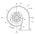
- FIG. 1 is a longitudinal cross-sectional view schematically showing a turbocharger according to some embodiments of the present invention
- FIG. 2 is a cross-sectional view schematically showing a turbine casing in FIG.
- a turbocharger is applied to internal combustion engines, such as vehicles, for example.
- the turbocharger has a turbine 10 and a compressor 12.
- the turbine 10 has a turbine housing 14 and a turbine moving blade (turbine impeller) 16 rotatably housed in the turbine housing 14, and the compressor 12 is rotatably housed in a compressor housing 18 and the compressor housing 18.
- an impeller (compressor impeller) 20 is an impeller (compressor impeller) 20.
- the turbine housing 14 and the compressor housing 18 are fixed relative to the bearing housing (casing) 22, and the turbine blades 16 of the turbine 10 and the impeller 20 of the compressor 12 mutually extend by means of a drive shaft (turbine rotor) 24 extending within the bearing housing 22. Is linked to Therefore, the turbine moving blade 16, the impeller 20 and the drive shaft 24 are arranged on the same axis.
- the turbine blades 16 of the turbine 10 are rotated, for example, by the exhaust gas discharged from the internal combustion engine, whereby the impeller 20 of the compressor 12 is rotated via the drive shaft 24. Then, the rotation of the impeller 20 of the compressor 12 compresses the intake air supplied to the internal combustion engine.
- the turbine housing 14 includes, for example, a turbine casing 26 and an end wall (back plate) 28 disposed at an opening of the turbine casing 26 on the bearing housing 22 side.
- the drive shaft 24 passes through the end wall 28.
- the end wall 28 is sandwiched between the turbine casing 26 and the bearing housing 22, and the bearing housing 22 rotatably supports the drive shaft 24 via the bearing 30.
- the compressor housing 18 also comprises, for example, a compressor casing 32 and an end wall 34 coupled to the compressor casing 32, and the drive shaft 24 passes through the end wall 34.
- the end wall 34 is integrally formed with the bearing housing 22.
- the turbine casing 26 has a cylindrical portion 36 accommodating the turbine moving blades 16 and a scroll portion (volute portion) 38 extending along the circumferential direction of the turbine moving blades 16 and the cylindrical portion 36.
- the cylindrical portion 36 and the scroll portion 38 are integrally formed by casting. According to this configuration, since the cylindrical portion 36 and the scroll portion 38 are integrally formed by casting, the turbine casing 26 can be easily manufactured.
- the turbine casing 26 has a fluid inlet 42 that communicates with the inlet of the scroll 38. The fluid outlet is formed by the tubular portion 36.
- the cylindrical portion 36 is formed in a cylindrical shape centered on the axis of the turbine moving blade 16, and the turbine moving blade 16 is accommodated on the base side (the bearing housing 22 side) thereof.
- the base side of the cylindrical portion 36 forms a cylindrical shroud 44 which defines the working channel 17 between itself and the turbine moving blade 16.
- the scroll portion 38 is formed in a spiral shape with an axis (center line) of the shroud 44 as a center.
- the scroll portion 38 has an outer peripheral wall (scroll outer peripheral wall) 46 and a partition wall 54.
- the outer circumferential wall 46 is continuous with one end of the shroud 44 and extends along the circumferential direction of the shroud 44.
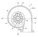
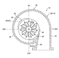
- FIG. 3-7 schematically illustrate cross-sections of a turbine according to some embodiments.
- the inlet (starting end) of the scroll portion 38 is at a position where the circumferential position (the circumferential position ⁇ ) of the turbine moving blade 16 is 0 °.
- the circumferential position ⁇ of 0 ° is defined as the position of the tip of the tongue 48.
- the tongue portion 48 is a portion where the outer peripheral wall 46 of the scroll portion 38 of the turbine casing 26 and the wall 50 of the introduction portion 42 intersect at an acute angle.
- the end of the scroll portion 38 is located at a position (circumferential position ⁇ ) in the circumferential direction of the turbine rotor blade 16 at 360 °. Accordingly, the circumferential position ⁇ of the end of the scroll portion 38 coincides with the circumferential position of the tongue portion 48.
- the value of the circumferential position ⁇ increases from the inlet of the scroll portion 38 toward the end, and the direction along the flow of fluid in the scroll portion 38 is a positive direction.
- An inner peripheral edge of the scroll portion 38 is defined by an imaginary circle 52 contacting the tongue portion 48 with an axis (center line) of the shroud 44 as a center, and an outer peripheral edge of the scroll portion 38 is formed by an outer peripheral wall 46 of the scroll portion 38 It is prescribed.
- the outer peripheral wall 46 has a C-shape in a cross section perpendicular to the circumferential direction of the shroud 44 at each circumferential position ⁇ .
- the partition wall 54 is disposed inside the outer peripheral wall 46 and extends in the circumferential direction of the shroud 44.
- the dividing wall 54 divides the inside of the outer peripheral wall 46 of the scroll portion 38 into a first scroll passage 56 and a second scroll passage 58, and the first scroll passage 56 and the second scroll passage 58 , And are adjacent to each other in the axial direction of the shroud 44.
- the outer peripheral edge of the partition wall 54 is integrally connected to the inner peripheral surface of the outer peripheral wall 46.
- the inner peripheral edge of the partition wall 54 is defined by an imaginary circle 52 tangent to the tongue 48 about the axis of the shroud 44.
- the internal combustion engine is a four-cylinder engine, and the first and fourth cylinders are connected to the first scroll passage 56, and the second and third cylinders are connected to the second scroll passage 58. Be done.
- the phase of the crank angle of the first cylinder and the fourth cylinder is 180 degrees different from the phase of the crank angle of the second cylinder and the third cylinder.
- the timing at which the exhaust gas flows from the first and fourth cylinders into the first scroll passage 56 differs from the timing at which the exhaust gas flows into the second scroll passage 58 from the second and third cylinders.
- the flow passage area A 1 of the first scroll flow passage 56 is formed in the circumferential direction of the shroud 44 in one space (first space) divided by the inside of the outer peripheral wall 46 and the dividing wall 54. It is defined as the area in the vertical cross section.
- a flow passage area A2 of the second scroll flow passage 58 is defined as the area of the other space (second space) divided by the inside of the outer peripheral wall 46 and the dividing wall 54.
- a total area of the flow passage area A1 of the first scroll flow passage 56 and the flow passage area A2 of the second scroll flow passage 58 is defined as a flow passage area A of the scroll portion 38.
- the distance from the flow path center C1 of the first scroll flow path 56 to the axis of the shroud 44 is defined as R1
- the distance from the flow path center C2 of the second scroll flow path 58 to the axis of the shroud 44 is defined as R2.
- the distance from the flow channel center of the flow channel combining the first scroll flow channel 56 and the second scroll flow channel 58 to the axis of the shroud 44 is defined as R.
- A1 / R1 is a ratio of the flow passage area A1 to the distance R1
- A2 / R2 is a ratio of the flow passage area A2 to the distance R2.
- a / R corresponds to the sum of the ratio A1 / R1 of the flow passage area A1 to the distance R1 of the first scroll flow passage 56 and the ratio A2 / R2 of the flow passage area A2 to the distance R2 of the second scroll flow passage 58.
- each of A1 / R1, A2 / R2 and A / R has the position of the turbine bucket 16 in the radial direction as r, and the first scroll passage 56, the second scroll passage 58, and these It is defined by following Formula (1), when the micro area element of the flow-path cross section of each of the flow path which put together is dA. If the areas A1 and A2 and the cross-sectional shapes of the flow path cross sections of the first scroll flow path 56 and the second scroll flow path 58 are known, the distances R1, R2 and R can be determined based on the equation (1). In a simplified manner, the distances R1, R2, and R are substituted by the distances from the axis of the shroud 44 to the respective centers of the first scroll channel 56, the second scroll channel 58, and the channel combining them. it can.
- the partition wall 54 provides a communication area between at least two of the first scroll channel 56, the second scroll channel 58, and the working channel 17. It has an enlarged portion 82 which partially expands in the circumferential direction of the shroud 44.
- the turbine casing 26 has the enlarged portion 82 that enlarges the communication area between at least two of the first scroll passage 56, the second scroll passage 58, and the working passage 17,
- the thickness of the core increases in the portion corresponding to the portion 82. As a result, the strength of the core for casting the turbine casing 26 can be increased.
- the miniaturized turbine 10 can be provided at low cost with high productivity.
- the enlarged portion 82 includes at least one notch 60 provided on the inner circumferential side of the partition wall 54.
- the communication area of the first scroll channel 56 and the second scroll channel 58 is enlarged by the notch 60 provided in the partition wall 54, and the core thickness is increased at the portion corresponding to the notch 60. Becomes thicker. As a result, the strength of the core for casting the turbine casing 26 can be increased.
- the circumferential position of the shroud 44 is represented with the position of the tongue 48 at 0 degrees and the flow direction of the fluid as the positive direction.
- the at least one notch 60 includes downstream notches 61 and 62 extending from the position of 90 degrees or more and 270 degrees or less in the circumferential direction of the shroud 44 to the downstream in the fluid flow direction.
- the downstream side notches 61 and 62 have upstream ends at positions of 90 degrees or more and 270 degrees or less.
- the communication area of the first scroll passage 56 and the second scroll passage 58 is enlarged by the downstream notches 61, 62 provided in the partition wall 54, and the downstream notches 61, 62 are accommodated.
- the thickness of the core increases in the area where As a result, the strength of the core for casting the turbine casing 26 can be increased.
- the flow rate of the fluid is smaller than that on the upstream side. Therefore, by providing the downstream side notches 61 and 62 as the notches 60, it is possible to suppress fluctuations in the flow velocity and pressure of the fluid.
- the downstream notches 61, 62 have an upstream end in the fluid flow direction at a position 180 degrees circumferentially of the shroud 44. Then, the downstream notches 61 and 62 gradually or gradually expand in the fluid flow direction, and the partition wall 54 is at the position of 180 degrees or more and 270 degrees or less in the circumferential direction of the shroud 44 within the outer peripheral wall 46 It becomes flush with the circumference.
- the downstream notch 61 expands along the inner peripheral edge of the partition wall 54 at the upstream end or the tangential direction of the imaginary circle 52.
- the downstream notch 62 gradually or gradually expands from the upstream end to the downstream end, and at the 270 degree position, the inner circumferential surface and the surface of the outer circumferential wall 46 become one.
- FIG. 11 is a graph in which the circumferential position ⁇ around the axis of the shroud 44 is taken on the horizontal axis, and A / R is taken on the vertical axis, showing the relationship between the circumferential position ⁇ and A / R.
- the A / R (A1 / R1, A2 / R2) of each of the first scroll channel 56 and the second scroll channel 58 is smoothly reduced, and The total value A / R decreases smoothly.
- the downstream side notches 61 and 62 have upstream ends in the fluid flow direction at positions of 180 degrees or more and 270 degrees or less in the circumferential direction of the shroud 44.
- a / R of the downstream side notches 61 and 62 is the total A / R of the first scroll passage 56 and the second scroll passage 58 upstream of the downstream notches 61 and 62 It has a shape that becomes smaller than the A / R distribution when linearly decreasing toward 360 degrees. According to this configuration, the A / Rs of the first scroll passage 56 and the second scroll passage 58 in the basin where the downstream side notches 61 and 62 are formed are the first in the upstream of the downstream side notches 61 and 62.
- the downstream notches 61 and 62 are formed by the A / R sum of the 1 scroll passage 56 and the second scroll passage 58 being smaller than the A / R distribution in the case of a linear decrease toward 360 degrees. Expansion of the flow passage area in the basin is suppressed, and fluctuations in the flow velocity and pressure of the fluid are suppressed.
- the A / R of the downstream cutouts 61 and 62 is the first scroll channel 56 and the second scroll upstream of the downstream cutouts 61 and 62.
- the A / R sum of the flow path 58 has a shape that is 80% or less of the A / R distribution when linearly decreasing toward 360 degrees. According to this configuration, the A / Rs of the first scroll passage 56 and the second scroll passage 58 in the basin where the downstream side notches 61 and 62 are formed are the first in the upstream of the downstream side notches 61 and 62.
- the downstream side notches 61 and 62 are formed by the A / R sum of the 1 scroll passage 56 and the second scroll passage 58 being 80% or less of the A / R distribution when linearly decreasing toward 360 degrees.
- the expansion of the flow passage area in the above-mentioned basin is suppressed, and the fluctuation of the flow velocity and pressure of the fluid is suppressed.
- a / R of the downstream side notches 61 and 62 is the first scroll flow path 56 or the change in the circumferential position ⁇ . It decreases at the same ratio as A / R of the second scroll flow path 58.
- the straight line representing A / R of the flow path (scroll flow path) after the first scroll flow path 56 and the second scroll flow path 58 join is the first scroll flow. It is located on an extension of a straight line representing A / R (A1 / R1, A2 / R2) of the path 56 or the second scroll flow path 58.
- a / R at the downstream notch where the first scroll passage 56 and the second scroll passage 58 join is A / R (A 1 of the first scroll passage 56 or the second scroll passage).
- the flow rate of the fluid (exhaust gas) can be smoothed by decreasing in the same ratio as / R1, A2 / R2).
- the enlarged portion 82 includes at least one notch 60 provided on the inner circumferential side of the partition wall 54.
- the at least one notch 60 includes a plurality of notches 60 that are rotationally symmetrically disposed about the axis of the shroud 44.
- the communication area of the first scroll passage 56 and the second scroll passage 58 is enlarged by the plurality of notches 60 arranged in rotational symmetry around the axis of the shroud 44, and the plurality of notches 60
- the thickness of the core increases in the part corresponding to. As a result, the strength of the core for casting the turbine casing 26 can be increased.
- notches 60 at positions of 90 degrees or more and 180 degrees or less and 270 degrees or more and 360 degrees or less in the circumferential direction of the shroud 44 , “Upstream notch 63” and “downstream notch 64”.
- the upstream cutout 63 and the downstream cutout 64 have the same shape, are provided over a wide area, and are in contact with the tongue 48 described above. It cuts out in the shape of a circular arc from the basic circle 52 toward the outer peripheral wall (scroll outer peripheral wall). Thereby, the upstream notch 63 and the downstream notch 64 are gradually or gradually enlarged in the fluid flow direction, and then gradually or gradually reduced. According to this configuration, the communication area of the first scroll passage 56 and the second scroll passage 58 is enlarged by the upstream notch 63 and the downstream notch 64, and the upstream notch 63 and the downstream notch 64 The thickness of the core increases in the part corresponding to. As a result, the strength of the core for casting the turbine casing 26 can be increased at two points.
- the first cutout 65, the second cutout 66, the third cutout 67, and the fourth cutout 68 have the same shape, and the shroud 44 is shown in FIG. It is equally provided in the circumferential direction.
- the first cutaway portion 65, the second cutaway portion 66, the third cutaway portion 67, and the fourth cutaway portion 68 are similar to the upstream cutaway portion 63 and the downstream cutaway portion 64 described above,
- the virtual circle 52 in contact with the tongue portion 48 mentioned above is notched in an arc shape toward the outer peripheral wall 46 (scroll outer peripheral wall), but is narrower than the upstream side notch portion 63 and the downstream side notch portion 64 described above It is provided in the range. Therefore, the radii of the first notch 65, the second notch 66, the third notch 67, and the fourth notch 68 are smaller than those of the upstream notch 63 and the downstream notch 64 described above.
- the communication area of the first scroll passage 56 and the second scroll passage 58 is enlarged by the first cutaway portion 65, the second cutaway portion 66, the third cutaway portion 67, and the fourth cutaway portion 68.
- the thickness of the core is increased in portions corresponding to the first notch 65, the second notch 66, the third notch 67, and the fourth notch 68.
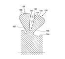
- FIG. 12 is a cross-sectional view schematically showing a turbine casing in FIG. 7, and FIG. 13 is a view schematically showing a through hole in FIG.
- the enlarged portion 82 includes at least one through hole 69 provided in the partition wall 54.
- the first scroll channel 56 and the second scroll channel 58 communicate with each other through the through hole 69 provided in the partition wall 54, and the core portion corresponding to the first scroll channel 56 And the portion of the core corresponding to the second scroll flow path 58 are connected at the portion of the core corresponding to the through hole 69.
- the strength of the core for casting the turbine casing 26 can be increased.
- some embodiments include a plurality of through holes 70, 71, 72 disposed about the axis of the shroud 44.
- the first scroll channel 56 and the second scroll channel 58 communicate with each other by the plurality of through holes 70, 71, 72 provided in the partition wall 54, and the first scroll channel 56
- the corresponding core portion and the core portion corresponding to the second scroll flow path 58 are connected at the core portion corresponding to the plurality of through holes 70, 71, 72.
- a position between 0 degrees and 90 degrees, a position between 90 degrees and 180 degrees, and a position between 180 degrees and 270 degrees in the circumferential direction of the shroud 44 is provided at each of the following positions.
- one through hole 70, 71, 72 is provided at the 45 degree position, the 135 degree position, and the 225 degree position, respectively.
- the diameters of the through holes 70, 71, 72 gradually decrease along the fluid flow direction. In some embodiments, the diameter decreases in order of through holes 70 provided at 45 degrees, through holes 71 provided at 135 degrees, and through holes 72 provided at 225 degrees.
- the first scroll passage is formed by the through hole 70 provided at the 45 degree position, the through hole 70 provided at the 135 degree position, and the through hole 71 provided at the 225 degree position.
- the area of communication between 56 and the second scroll passage 58 is enlarged.
- the core portion corresponding to the first scroll passage 56 and the core portion corresponding to the second scroll passage 58 are provided with the through hole 70 provided at the 45 degree position, and the 135 degree position Are connected at the core portion corresponding to the through hole 70 provided in the case and the through hole 71 provided at the position of 225 degrees.
- the strength of the core for casting the turbine casing 26 can be increased.
- the partition wall 54 has a flow straightening portion 73 around the through hole 69. According to this configuration, the flow of the fluid flowing around the through hole 69 can be adjusted, and the leak flow between the first scroll channel 56 and the second scroll channel 58 can be suppressed.
- the flow straightening unit 73 is provided from one flow passage (eg, the first scroll flow passage 56) to the other flow passage (eg, the second scroll flow passage 58). It is for suppressing the leak of the fluid.
- the flow straightening portion 73 may have a thickened portion 74 that gradually or gradually thickens toward the downstream side on the upstream side of the through hole 69, and on the downstream side of the through hole 69. And a reduced thickness portion 75 which gradually or gradually becomes thinner toward the upstream side.
- the fluid flows along the surface (inclined surface) of the thick portion 74, and the flow of the fluid toward the through hole 69 is suppressed. Then, even if the fluid is drawn to the through hole 69 as it passes through the side surface of the through hole 69, the fluid flows along the surface (inclined surface) of the reduced thickness portion 75 and passes through the through hole 69 Flow in the direction of Thereby, the leak of the fluid which goes to the other flow path from one flow path can be controlled.
- FIGS. 8 and 9 are conceptual diagrams showing trajectories of inner peripheral edges of partition walls of a turbine casing according to some embodiments.
- the inner peripheral edge of the partition wall 54 of the turbine casing 26 is indicated by a two-dot chain line.
- the enlarged portion 82 includes at least one bend portion 76 provided on the inner circumferential side of the partition wall 54. According to this configuration, by the bend portion 76 provided on the inner peripheral side of the partition wall 54, the communication area of the first scroll channel 56 and the working channel 17 or the second scroll channel 58 and the working channel 17 The communication area is enlarged.
- a core connection portion connecting the core portion corresponding to the first scroll flow path 56 and the core portion corresponding to the operation flow path 17 or the core corresponding to the second scroll flow path 58 The thickness of the core becomes thick at the connecting portion of the core connecting the portion of the core and the portion of the core corresponding to the working channel 17. As a result, the strength of the core for casting the turbine casing 26 can be increased.
- the at least one bend section 76 includes at least one first bend section 77, 78 that expands the throat section 57 of the first scroll channel 56 facing the working channel 17; And at least one second bend portion 79, 80 for enlarging the throat portion 59 of the second scroll passage 58 facing the second scroll passage 58.
- the core portion corresponding to the throat portion 57 of the first scroll flow passage 56 becomes thicker, and the second bend portions 79 and 80 are formed. Due to the provision, the core portion corresponding to the throat portion 59 of the second scroll channel 58 becomes thick.
- the core is thickened in both of the core connecting portion connecting the child portion and the core portion corresponding to the working channel 17. As a result, the strength of the core for casting the turbine casing 26 can be increased.
- first bends 77 and 78 and second bends 79 and 80 are alternately provided at positions dividing the shroud 44 into four equal parts in the circumferential direction. Be Therefore, two first bend portions 77 and 78 and two second bend portions 79 and 80 are provided in the circumferential direction of the shroud 44. Specifically, in the circumferential direction of the shroud 44, the first bends 77 and 78 are provided around the 180 degree position and the 360 degree position, and the 90 degree and 270 degree positions are centered. The second bends 79 and 80 are provided on the lower end.
- the communication area between the first scroll passage 56 and the working passage 17 is enlarged at the first bends 77 and 78, so that the core meat is formed at the portion where the first bends 77 and 78 are formed. It becomes thicker. Further, since the communication area between the first scroll passage 56 and the working passage 17 is enlarged at the second bends 79 and 80, the thickness of the core becomes thicker at the portion where the throats 57 and 59 are formed. Thereby, the strength of the core for casting the turbine casing 26 can be enhanced.
- the first bends 77, 78 enlarge the throat 57 of the first scroll passage 56 and reduce the throat 59 of the second scroll passage 58
- the second bends 79 and 80 enlarge the throat 59 of the second scroll passage 58 and reduce the throat 57 of the first scroll passage 56.
- the throat portion 57 of the first scroll passage 56 is most enlarged at the position where the circumferential direction of the shroud 44 is 180 degrees and the position where it is 360 degrees, and the throat portion of the second scroll passage 58 59 is the smallest.
- the throat portion 59 of the second scroll passage 58 is most expanded at the position where the circumferential direction of the shroud 44 is 90 degrees and the position where it is 270 degrees, and the throat portion 57 of the first scroll passage 56 is the most It is reduced.
- the first bends 77, 78 expand the throat 57 of the first scroll passage 56 and close the throat 59 of the second scroll passage 58
- the second bends 79 and 80 enlarge the throat 59 of the second scroll passage 58 and close the throat 57 of the first scroll passage 56.
- FIG. 14 is a developed schematic view showing the partition wall of the turbine casing in FIG.
- the inner peripheral edge of the partition wall has a wave shape (sinusoidal shape). Have.
- the throat portion 57 of the first scroll passage 56 is most enlarged at the position where the circumferential direction of the shroud 44 is 180 degrees and the position where it is 360 degrees, and the throat portion of the second scroll passage 58 59 is closed.
- the throat portion 59 of the second scroll passage 58 is most enlarged at the position where the circumferential direction of the shroud 44 is 90 degrees and the position where it is 270 degrees, and the throat portion 57 of the first scroll passage 56 is closed. Be done.
- FIG. 10 is a developed schematic view showing a partition wall of a turbine casing according to an embodiment.
- the inner peripheral edge of the partition wall 54 has a rectangular wave shape.
- the boundary 81 of the dividing wall 54 located at the boundary between the first bends 77, 78 and the second bends 79, 80 is provided in the shroud 44 to facilitate fluid flow. It extends obliquely with respect to the radial direction.
- the first bends 77, 78 expand the throat 57 of the first scroll passage 56 and close the throat 59 of the second scroll passage 58, In the throat portion 57 of the first scroll channel 56, an enlarged portion (opening) of a development view rectangle is formed.
- the second bends 79, 80 enlarge the throat 59 of the second scroll passage 58 and close the throat 57 of the first scroll passage 56, and the throat 57 of the first scroll passage 56 An enlarged portion (opening) of the development view rectangle is formed.
- the communication area between the first scroll passage 56 and the working passage 17 is enlarged at the first bends 77 and 78, so that the core meat is formed at the portion where the first bends 77 and 78 are formed. It becomes thicker. Further, since the communication area between the first scroll passage 56 and the working passage 17 is enlarged at the second bend portions 79, 80, the thickness of the core becomes thicker at the portion where the second bend portions 79, 80 are formed. . Thereby, the strength of the core for casting the turbine casing 26 can be enhanced.
- FIG. 15 is a front view schematically showing a core for casting a turbine casing according to an embodiment
- FIG. 14 is a view schematically showing a cross section of the core shown in FIG.
- FIGS. 17 to 19 are schematic diagrams schematically illustrating the core of a core for casting a turbine casing according to some embodiments.
- a forming portion 146, a dividing wall forming portion 154 for dividing a runner corresponding to the dividing wall 54, and a reinforcing portion 182 disposed in a portion of the runner corresponding to the enlarged portion 82 are provided. According to this configuration, the thickness of the core is increased at the reinforcing portion 182, and the strength of the core 126 for casting the turbine casing 26 can be enhanced.
- a core 126 for casting the turbine casing 26 forms a runner corresponding to the turbine casing 26 with the main mold (not shown).
- the core 126 includes a cylindrical portion forming portion 136 corresponding to the cylindrical portion 36 and a scroll forming portion 138 corresponding to the scroll portion 38.
- the cylindrical portion forming portion 136 is formed in a cylindrical shape having the same outer peripheral shape as the inner peripheral shape of the cylindrical portion 36.
- a shroud forming portion 144 corresponding to the shroud 44 on the side of the scroll forming portion 138 is formed.
- the shroud forming portion 144 is for dividing a runner corresponding to the shroud 44 described above between the main mold and the main mold, and forms a boundary between the cylindrical portion forming portion 136 and the scroll forming portion 138.
- the scroll forming portion 138 is formed in a spiral shape having the same outer peripheral shape as the inner peripheral shape of the outer peripheral wall 46 with the axis (center line) of the cylindrical portion forming portion 136 as a center.
- the scroll forming portion 138 includes an outer peripheral wall forming portion 146 corresponding to the outer peripheral wall 46 (scroll outer peripheral wall), and a partition wall forming portion 154 corresponding to the partition wall 54.
- the outer peripheral wall forming portion 146 is for dividing a runner corresponding to the outer peripheral wall 46 described above with the main mold, and is centered on the axis (center line) of the shroud forming portion 144 and is within the outer peripheral wall 46. It is formed in a spiral shape having the same outer peripheral shape as the peripheral shape.
- the partition wall forming portion 154 is for partitioning a runner corresponding to the partition wall 54 described above with the main mold, and has the same outer periphery as the shape of the partition wall 54 centering on the axis of the shroud forming portion 144 It is formed in a V-shaped cross section having a shape.
- the partition wall forming portion 154 partitions the outer peripheral wall forming portion 146 into the first scroll forming portion 156 and the second scroll forming portion 158. Then, the first scroll forming unit 156 partitions a runner corresponding to the first scroll channel 56, and the second scroll forming unit 158 partitions a runner corresponding to the second scroll channel 58. Further, the partition wall forming portion 154 includes a reinforcing portion 182. The reinforcing portion 182 is disposed in the portion of the runner corresponding to the above-described enlarged portion 82, and the position, size, and range are appropriately set.
- the reinforcement 182 includes a notch reinforcement 160 disposed in the portion of the runner corresponding to the notch 60. According to this configuration, the thickness of the core 126 is increased at the notch reinforcing portion 160, and the strength of the core 126 for casting the turbine casing 26 can be enhanced. Moreover, according to this configuration, even if the turbine casing 26 is small, the turbine casing 26 can be easily manufactured by casting.
- the notch reinforcement 160 includes a downstream reinforcement 161 disposed in the portion of the runner corresponding to the downstream notch 61.
- the thickness of the core 126 is increased at the downstream side reinforcing portion 161, and the strength of the core 126 for casting the turbine casing 26 can be enhanced.
- the downstream reinforcing portion 161 between the first scroll forming portion 156 and the second scroll forming portion 158 is provided in a region corresponding to the downstream side notch 61. Therefore, the first scroll forming portion 156 and the second scroll forming portion 158 merge in an area corresponding to the downstream side notch 61.
- the scroll forming portion 138 is reinforced in the region corresponding to the downstream side notch portion 61, and the connecting portion 157 between the first scroll forming portion 156 and the shroud forming portion 144, the second scroll forming portion 158, and the shroud forming portion
- the strength of the connecting portion 159 can be increased.
- the overall strength of the scroll forming portion 138 can be increased, and the strength of the core 126 for casting the turbine casing 26 can be increased.
- the reinforcing portion 182 includes at least one narrowing portion 183 provided in a narrow space on the inner peripheral side of the partition wall forming portion 154. According to this configuration, the thickness of the core 126 is increased at the narrow wall portion 183, and the strength of the core 126 for casting the turbine casing 26 can be enhanced.
- a narrow walled portion 183 is provided in the narrowing corresponding to the upstream notch 63 and the narrowing corresponding to the downstream notch 64.
- the narrowing portion 183 is formed between the first scroll forming portion 156 and the second scroll forming portion 158 in a region corresponding to the upstream notch 63 and a region corresponding to the downstream notch 64.
- the first scroll forming portion 156 and the second scroll forming portion 158 merge in an area corresponding to the upstream notch 63 and an area corresponding to the downstream notch 64.
- the scroll forming portion 138 is reinforced in the region corresponding to the upstream notch portion 63 and the region corresponding to the downstream notch portion 64, and the connecting portion 157 of the first scroll forming portion 156 and the shroud forming portion 144
- the strength of the connection portion 159 between the scroll forming portion 158 and the shroud forming portion 144 can be increased in two regions, that is, the region corresponding to the upstream cutout 63 and the region corresponding to the downstream cutout 64.
- the overall strength of the scroll forming portion 138 can be increased, and the strength of the core 126 for casting the turbine casing 26 can be increased.
- the core 126 for casting the turbine casing 26 shown in FIG. 6 has a region corresponding to the first notch 65, a region corresponding to the second notch 66, a region corresponding to the third notch 67, In the region corresponding to the four notches 68, a narrowing portion 183 is provided in a narrow space between the first scroll forming portion 156 and the second scroll forming portion 158. And, in fact, the first scroll is performed in the region corresponding to the first cutout 65, the region corresponding to the second cutout 66, the region corresponding to the third cutout 67, and the region corresponding to the fourth cutout 68.
- the forming unit 156 and the second scroll forming unit 158 merge.
- the scroll forming portion 138 is balanced in the region corresponding to the first cutout 65, the region corresponding to the second cutout 66, the region corresponding to the third cutout 67, and the region corresponding to the fourth cutout 68.
- the strength of the connecting portion 157 of the first scroll forming portion 156 and the shroud forming portion 144 and the connecting portion 159 of the second scroll forming portion 158 and the shroud forming portion 144 is well reinforced, a region corresponding to the first cutout portion 65, second
- the height can be increased in four areas: an area corresponding to the notch 66, an area corresponding to the third notch 67, and an area corresponding to the fourth notch 68.
- the overall strength of the scroll forming portion 138 can be increased, and the strength of the core 126 for casting the turbine casing 26 can be increased.
- the reinforcement portion 182 includes at least one post portion 169 disposed in the runner corresponding to the partition wall 54. According to this configuration, two regions (the first scroll forming portion 156 and the second scroll forming portion 158) of the outer peripheral wall forming portion 146 divided by the dividing wall forming portion 154 are connected via the columnar portion 169. As a result, the strength of the core 126 for casting the turbine casing 26 can be increased.
- the core for casting the turbine casing 26 shown in FIG. 7 includes, as shown in FIG. 18, at least one column portion 169 disposed in a runner corresponding to the partition wall 54.
- the columnar portion 169 is provided in a region corresponding to the through hole 69 provided in the partition wall 54.
- the first scroll forming portion 156 and the second scroll forming portion 158 are connected by the columnar portion 169 in the region corresponding to the through holes 70, 71, 72 provided in the dividing wall 54.
- the scroll forming portion 138 is reinforced in the region corresponding to the through holes 70, 71, 72 provided in the partition wall 54, and the second scroll forming portion is formed with the connecting portion 157 of the first scroll forming portion 156 and the shroud forming portion 144.
- the strength of the connecting portion 159 of the portion 158 and the shroud forming portion 144 can be increased.
- the overall strength of the scroll forming portion 138 can be increased, and the strength of the core 126 for casting the turbine casing 26 can be increased.
- One columnar portion 169 is provided at a position not less than 180 degrees and not more than 270 degrees. Specifically, the columnar portion 169 is provided at the position of 45 degrees, the position of 135 degrees, and the position of 225 degrees. In addition, the columnar part 169 becomes smaller stepwise along the fluid flow direction, and in the example shown in FIG. 8, the columnar part 169 provided at the position of 45 degrees, the columnar part 169 provided at the position of 135 degrees, The columnar parts 169 provided at the position of 225 degrees become smaller in order.
- the scroll forming portion 138 is reinforced in a well-balanced manner at the 45 ° position, the 135 ° position and the 225 ° position, and the connecting portion 157 of the first scroll forming portion 156 and the shroud forming portion 144 and the second scroll forming portion
- the strength of 158 and the connection portion 159 of the shroud forming portion 144 can be increased at three positions of 45 degrees, 135 degrees and 225 degrees.
- the overall strength of the scroll forming portion 138 can be increased, and the strength of the core 126 for casting the turbine casing 26 can be increased.
- the reinforcing portion 182 includes at least one thick portion 176 that displaces the inner circumferential side of the partition wall in the axial direction of the shroud 44. According to this configuration, the thickness of the core is increased in the thick portion 176, and the strength of the core 126 for casting the turbine casing 26 can be enhanced.
- At least one thick portion 176 forms a first thick portion (not shown) that forms the first bends 77, 78 and a second bend 79, 80. And a second thick portion 179.
- the core 126 for casting the turbine casing 26 shown in FIGS. 8 and 9 has a first thick portion (not shown) and a second thick portion at positions equally dividing the circumferential direction of the shroud forming portion 144 into four. 179 and are alternately provided. Therefore, two first thick portions and two second thick portions 179 are provided in the circumferential direction of the shroud forming portion 144, respectively. Specifically, the first thick portion is provided centered on the position where the angle is 180 degrees and 360 degrees in the circumferential direction of the shroud forming portion 144, and the position where the temperature is about 90 degrees and 270 degrees A thick portion 179 is provided.
- first scroll forming portion 156 is reinforced by the first thick portion
- second scroll forming portion 158 is reinforced by the second thick portion 179.
- the strength of the connecting portion 157 of the first scroll forming portion 156 and the shroud forming portion 144 can be enhanced at the first thick portion
- the strength of the connecting portion 159 of the second scroll forming portion 158 and the shroud forming portion 144 is It can be enhanced by the second thick portion 179.
- the core 126 for casting the turbine casing 26 shown in FIG. 8 is a connecting portion 157 between the first scroll forming portion 156 and the shroud forming portion 144 at the first thick portion in the circumferential direction of the shroud forming portion 144.
- the second scroll forming portion 158 and the connecting portion 159 of the shroud forming portion 144 are thinner. Further, while the connecting portion 157 of the first scroll forming portion 156 and the shroud forming portion 144 becomes thicker in the second thick portion 179, the connecting portion 159 of the second scroll forming portion 158 becomes thinner.
- a core 126 for casting the turbine casing 26 shown in FIG. 9 has a connecting portion 157 of the first scroll forming portion 156 and the shroud forming portion 144 at the first thick portion in the circumferential direction of the shroud forming portion. While the wall thickness is increased, the connection portion 159 of the second scroll forming portion 158 and the shroud forming portion 144 is disconnected. In addition, while the connecting portion 157 of the second scroll forming portion 158 becomes thick in the second thick portion 179, the connecting portion 159 of the first scroll forming portion 156 and the shroud forming portion 144 is disconnected. However, since the scroll forming portion 138 can enhance the strength as a whole, the strength of the core for casting the turbine casing 26 can be enhanced.
- core 126 for casting turbine casing 26 shown in FIG. 10 has a first thickness in the circumferential direction of shroud forming portion 144, similarly to core 126 for casting turbine casing 26 shown in FIG. While the connecting portion 157 of the first scroll forming portion 156 and the shroud forming portion 144 becomes thick in the thick portion, the connecting portion 159 of the second scroll forming portion 158 and the shroud forming portion 144 is disconnected. Further, while the connecting portion 159 of the second scroll forming portion 158 and the shroud forming portion 144 becomes thick in the second thick portion, the connecting portion 157 of the first scroll forming portion 156 is disconnected. However, since the scroll forming portion 138 can enhance the strength as a whole, the strength of the core for casting the turbine casing 26 can also be enhanced.
- the method of manufacturing the turbine casing 26 comprises the steps of providing a core 126 for casting the turbine casing 26, and casting the turbine casing 26 using the provided core 126, including. According to this procedure, even if the turbine casing 26 is small, the turbine casing 26 can be easily manufactured by casting. Therefore, a miniaturized turbine can be provided at high cost with low productivity.
- the steps of installing the main mold for casting the turbine casing 26 installing the core 126 described above in the main mold, pouring hot water into the mold and casting the turbine casing 26 And the step of According to this procedure, even if the turbine casing 26 is small, the turbine casing 26 can be easily manufactured by casting. Therefore, a miniaturized turbine can be provided at high cost with low productivity.
- the present invention is not limited to the above-described embodiments, and includes the embodiments in which the above-described embodiments are modified, and the combination of these embodiments as appropriate.
- the possibility of combination of embodiments is also disclosed by a combination of the original claims of the present application or the original claims of the basic application in the case where the present invention is accompanied by a claim of priority.
Abstract
Description
また、上記(1)の構成によれば、タービンケーシングが第1スクロール流路、第2スクロール流路及び作動流路のうち少なくとも2つの間の連通面積を拡大する拡大部を有しており、拡大部に対応する部分で中子の肉厚が厚くなる。この結果、タービンケーシングを鋳造するための中子の強度を高めることができる。
上記(2)の構成によれば、区画壁に設けられた切欠部で第1スクロール流路と第2スクロール流路の連通面積が拡大され、切欠部に対応する部分で中子の肉厚が厚くなる。この結果、タービンケーシングを鋳造するための中子の強度を高めることができる。
上記(3)の構成によれば、区画壁の下流側切欠部で第1スクロール流路と第2スクロール流路の連通面積が拡大され、下流側切欠部に対応する部分で中子の肉厚が厚くなる。この結果、タービンケーシングを鋳造するための中子の強度を高めることができる。
また、第1スクロール流路及び第2スクロール流路の下流側では、上流側に比べて流体の流量が少ない。このため、切欠部として下流側切欠部を設けることで、流体の流速や圧力の変動を抑制することができる。
上記(4)の構成によれば、シュラウドの軸線の周りに回転対称に配置された複数の切欠部で第1スクロール流路と第2スクロール流路の連通面積が拡大され、複数の切欠部に対応する部分で中子の肉厚が厚くなる。この結果、タービンケーシングを鋳造するための中子の強度を高めることができる。
下流側切欠部を設けた場合、下流側切欠部が設けられた流域で、第1スクロール流路と第2スクロール流路が合流する。このため、単に下流側切欠部を設けた場合、第1スクロール流路又は第2スクロール流路を流れてきた流体にとって、下流側切欠部が形成された流域で流路が広くなり、流体の速度や圧力が変動してしまう。
上記(5)の構成によれば、下流側切欠部が形成された流域における第1スクロール流路と第2スクロール流路とを合わせたA/Rが、下流側切欠部よりも上流における、第1スクロール流路と第2スクロール流路のA/R合計が360度に向けて線形減少した場合のA/R分布よりも小さくなることで、下流側切欠部が形成された流域での流路面積の拡大が抑制され、流体の流速や圧力の変動が抑制される。
上記(6)の構成によれば、区画壁に設けられた貫通穴で第1スクロール流路と第2スクロール流路とが連通しており、第1スクロール流路に対応する中子の部分と第2スクロール流路に対応する中子の部分とが、貫通穴に対応する中子の部分で接続される。この結果、タービンケーシングを鋳造するための中子の強度を高めることができる。
上記(7)の構成によれば、貫通穴の周りを流れる流体の流れが整えられ、第1スクロール流路と第2スクロール流路の相互間における漏れ流れを抑制できる。
上記(8)の構成によれば、区画壁の内周側に設けられたベンド部によって、第1スクロール流路と作動流路の連通面積、又は第2スクロール流路と作動流路の連通面積が拡大される。この場合、第1スクロール流路に対応する中子の部分と作動流路に対応する中子の部分とを繋ぐ中子の連結部分、又は、第2スクロール流路に対応する中子の部分と、作動流路に対応する中子の部分とを繋ぐ中子の連結部分で中子の肉厚が厚くなる。この結果、タービンケーシングを鋳造するための中子の強度を高めることができる。
上記(9)の構成によれば、第1ベンド部を設けたことで、第1スクロール流路のスロート部に対応する中子の部分が肉厚になり、第2ベンド部を設けたことで第2スクロール流路のスロート部に対応する中子の部分が肉厚になる。このため、第1スクロール流路に対応する中子の部分と作動流路に対応する中子の部分とを連結する中子の連結部分、及び、第2スクロール流路に対応する中子の部分と作動流路に対応する中子の部分とを連結する中子の連結部分の両方で中子が肉厚になる。この結果、タービンケーシングを鋳造するための中子の強度を高めることができる。
上記(10)の構成によれば、タービンケーシングが小型であっても、タービンケーシングを鋳造により容易に製造することができる。このため、小型化されたタービンを高い生産性の下で低コストにて提供できる。
上記(11)の構成によれば、補強部で中子の肉厚が厚くなり、タービンケーシングを鋳造するための中子の強度を高めることができる。
上記(12)の構成によれば、狭隘肉部で中子の肉厚が厚くなり、タービンケーシングを鋳造するための中子の強度を高めることができる。
上記(13)の構成によれば、区画壁形成部により区分けされたスクロール外周壁形成部の2つの領域が柱状部を介して接続される。この結果、タービンケーシングを鋳造するための中子の強度を高めることができる。
上記(14)の構成によれば、厚肉部で中子の肉厚が厚くなり、タービンケーシングを鋳造するための中子の強度を高めることができる。
上記の構成によれば、タービンケーシングが小型であっても、タービンケーシングを鋳造により容易に製造することができる。
上記(16)の手順によれば、タービンケーシングが小型であっても、タービンケーシングを鋳造により容易に製造することができる。このため、小型化されたタービンを高い生産性の下で低コストにて提供できる。
例えば、「ある方向に」、「ある方向に沿って」、「中心」、或いは「中心とする」「同一の軸線上」等の相対的或いは絶対的な配置を表す表現は、厳密にそのような配置を表すのみならず、公差、若しくは、同じ機能が得られる程度の角度や距離をもって相対的に変位している状態も表すものとする。
また例えば、四角形状や円筒形状等の形状を表す表現は、幾何学的に厳密な意味での四角形状や円筒形状等の形状を表すのみならず、同じ効果が得られる範囲で、凹凸部や面取り部等を含む形状も表すものとする。
一方、一の構成要素を「備える」、「含む」、又は、「有する」という表現は、他の構成要素の存在を除外する排他的な表現ではない。
ターボチャージャは、タービン10と、コンプレッサ12とを有する。タービン10は、タービンハウジング14と、タービンハウジング14内に回転可能に収容されたタービン動翼(タービンインペラ)16とを有し、コンプレッサ12は、コンプレッサハウジング18と、コンプレッサハウジング18に回転可能に収容されたインペラ(コンプレッサインペラ)20とを有する。
また、コンプレッサハウジング18は、例えば、コンプレッサケーシング32と、コンプレッサケーシング32に結合された端壁34とからなり、駆動軸24は端壁34を貫通している。端壁34は、軸受ハウジング22と一体に形成されている。
外周壁46は、シュラウド44の一端側に連なり、シュラウド44の周方向に沿って延在している。
図3に示すように、スクロール部38の入口(開始端)は、タービン動翼16の周方向での位置(周方向位置θ)が0°の位置にある。なお、周方向位置θが0°の位置は、舌部48の先端の位置として定義される。舌部48は、タービンケーシング26のスクロール部38の外周壁46と導入部42の壁50とが鋭角に交わる部分である。
なお、周方向位置θの値は、スクロール部38の入口から末端に向かって増加するものとし、スクロール部38における流体の流れに沿う方向を正の方向とする。
区画壁54は、スクロール部38の外周壁46の内部を、第1スクロール流路56と第2スクロール流路58とに区画しており、第1スクロール流路56と第2スクロール流路58は、シュラウド44の軸線方向にて相互に隣接している。区画壁54の外周縁は外周壁46の内周面に一体に連なっている。区画壁54の内周縁は、シュラウド44の軸線を中心として、舌部48に接する仮想的な円52によって規定される。
A1/R1は、距離R1に対する流路面積A1の比であり、A2/R2は、距離R2に対する流路面積A2の比である。A/Rは、第1スクロール流路56の距離R1に対する流路面積A1の比A1/R1と第2スクロール流路58の距離R2に対する流路面積A2の比A2/R2の合計に相当する。

この構成によれば、タービンケーシング26が第1スクロール流路56,第2スクロール流路58及び作動流路17のうち少なくとも2つの間の連通面積を拡大する拡大部82を有しており、拡大部82に対応する部分で中子の肉厚が厚くなる。この結果、タービンケーシング26を鋳造するための中子の強度を高めることができる。
この構成によれば、区画壁54に設けられた切欠部60で第1スクロール流路56と第2スクロール流路58の連通面積が拡大され、切欠部60に対応する部分で中子の肉厚が厚くなる。この結果、タービンケーシング26を鋳造するための中子の強度を高めることができる。
また、第1スクロール流路56及び第2スクロール流路58の下流側では、上流側に比べて流体の流量が少ない。このため、切欠部60として下流側切欠部61,62を設けることで、流体の流速や圧力の変動を抑制することができる。
図4に示すように、幾つかの実施形態では、下流側切欠部62は、上流端から下流端に向けて漸次又は徐々に拡大し、270度の位置で外周壁46の内周面と面一となる。
この構成によれば、下流側切欠部61,62が形成された流域における第1スクロール流路56と第2スクロール流路58のA/Rが、下流側切欠部61,62よりも上流における第1スクロール流路56と第2スクロール流路58のA/R合計が360度に向けて線形減少した場合のA/R分布よりも小さくなることで、下流側切欠部61,62が形成された流域での流路面積の拡大が抑制され、流体の流速や圧力の変動が抑制される。
この構成によれば、下流側切欠部61,62が形成された流域における第1スクロール流路56と第2スクロール流路58のA/Rが、下流側切欠部61,62よりも上流における第1スクロール流路56と第2スクロール流路58のA/R合計が360度に向けて線形減少した場合のA/R分布の80%以下となることで、下流側切欠部61,62が形成された流域での流路面積の拡大が抑制され、流体の流速や圧力の変動が抑制される。
この構成によれば、第1スクロール流路56と第2スクロール流路58とが合流した下流側切欠部におけるA/Rが第1スクロール流路56又は第2スクロール流路のA/R(A1/R1,A2/R2)と同じ比率で減少し、流体(排ガス)の流れをスムースなものにできる。
幾つかの実施形態では、少なくとも1つの切欠部60は、シュラウド44の軸線の周りに回転対称に配置された複数の切欠部60を含んでいる。
この構成によれば、シュラウド44の軸線の周りに回転対称に配置された複数の切欠部60で第1スクロール流路56と第2スクロール流路58の連通面積が拡大され、複数の切欠部60に対応する部分で中子の肉厚が厚くなる。この結果、タービンケーシング26を鋳造するための中子の強度を高めることができる。
この構成によれば、上流側切欠部63と下流側切欠部64とで第1スクロール流路56と第2スクロール流路58の連通面積が拡大され、上流側切欠部63と下流側切欠部64に対応する部分で中子の肉厚が厚くなる。この結果、タービンケーシング26を鋳造するための中子の強度を二箇所で高めることができる。
図7及び図12に示すように、幾つかの実施形態では、拡大部82は、区画壁54に設けられた少なくとも1つの貫通穴69を含んでいる。
この構成によれば、区画壁54に設けられた貫通穴69で第1スクロール流路56と第2スクロール流路58とが連通しており、第1スクロール流路56に対応する中子の部分と第2スクロール流路58に対応する中子の部分とが、貫通穴69に対応する中子の部分で接続される。この結果、タービンケーシング26を鋳造するための中子の強度を高めることができる。
この構成によれば、区画壁54に設けられた複数の貫通穴70,71,72で第1スクロール流路56と第2スクロール流路58とが連通しており、第1スクロール流路56に対応する中子の部分と第2スクロール流路58に対応する中子の部分とが、複数の貫通穴70,71,72に対応する中子の部分で接続される。この結果、タービンケーシング26を鋳造するための中子の強度を高めることができる。
幾つかの実施形態では、45度の位置と、135度の位置と、225度の位置とに、それぞれ1つの貫通穴70,71,72が設けられる。
幾つかの実施形態では、貫通穴70,71,72の直径は、流体の流れ方向に沿って段階的に小さくなる。幾つかの実施形態では、45度の位置に設けた貫通穴70、135度の位置に設けた貫通穴71、225度の位置に設けた貫通穴72の順番に直径が小さくなる。
この構成によれば、貫通穴69の周りを流れる流体の流れが整えられ、第1スクロール流路56と第2スクロール流路58の相互間における漏れ流れを抑制できる。
図8及び図9に示すように、幾つかの実施形態では、拡大部82は、区画壁54の内周側に設けられた少なくとも1つのベンド部76を含んでいる。
この構成によれば、区画壁54の内周側に設けられたベンド部76によって、第1スクロール流路56と作動流路17の連通面積、又は第2スクロール流路58と作動流路17の連通面積が拡大される。この場合、第1スクロール流路56に対応する中子の部分と作動流路17に対応する中子の部分とを繋ぐ中子の連結部分、又は、第2スクロール流路58に対応する中子の部分と、作動流路17に対応する中子の部分とを繋ぐ中子の連結部分で中子の肉厚が厚くなる。この結果、タービンケーシング26を鋳造するための中子の強度を高めることができる。
この構成によれば、第1ベンド部77,78を設けたことで、第1スクロール流路56のスロート部57に対応する中子の部分が肉厚になり、第2ベンド部79,80を設けたことで第2スクロール流路58のスロート部59に対応する中子の部分が肉厚になる。このため、第1スクロール流路56に対応する中子の部分と作動流路17に対応する中子の部分とを連結する中子の連結部分、及び、第2スクロール流路58に対応する中子の部分と作動流路17に対応する中子の部分とを連結する中子の連結部分の両方で中子が肉厚になる。この結果、タービンケーシング26を鋳造するための中子の強度を高めることができる。
幾つかの実施形態では、図14に示すように、ベンド部76を形成したことにより、図14に示すように、展開図にて、区画壁の内周縁は、波形状(正弦波形状)を有する。
幾つかの実施形態では、ベンド部を形成したことにより、図10に示すように、展開図にて、区画壁54の内周縁は、矩形波形状を有する。
幾つかの実施形態では、第1ベンド部77,78と第2ベンド部79,80との境界に位置する区画壁54の境界部81は、流体の流れを円滑にするように、シュラウド44の半径方向に対して傾斜して延在している。
この構成によれば、補強部182で中子の肉厚が厚くなり、タービンケーシング26を鋳造するための中子126の強度を高めることができる。
この構成によれば、切欠補強部160で中子126の肉厚が厚くなり、タービンケーシング26を鋳造するための中子126の強度を高めることができる。
また、この構成によれば、タービンケーシング26が小型であっても、タービンケーシング26を鋳造により容易に製造することができる。
この構成によれば、下流側補強部161で中子126の肉厚が厚くなり、タービンケーシング26を鋳造するための中子126の強度を高めることができる。
この構成によれば、狭隘肉部183で中子126の肉厚が厚くなり、タービンケーシング26を鋳造するための中子126の強度を高めることができる。
この構成によれば、区画壁形成部154により区分けされた外周壁形成部146の2つの領域(第1スクロール形成部156と第2スクロール形成部158)が柱状部169を介して接続される。この結果、タービンケーシング26を鋳造するための中子126の強度を高めることができる。
この構成によれば、厚肉部176で中子の肉厚が厚くなり、タービンケーシング26を鋳造するための中子126の強度を高めることができる。
この手順によれば、タービンケーシング26が小型であっても、タービンケーシング26を鋳造により容易に製造することができる。このため、小型化されたタービンを高い生産性の下で低コストにて提供できる。
この手順によれば、タービンケーシング26が小型であっても、タービンケーシング26を鋳造により容易に製造できる。このため、小型化されたタービンを高い生産性の下で低コストにて提供できる。
12 コンプレッサ
14 タービンハウジング
16 タービン動翼
17 作動流路
18 コンプレッサハウジング
20 インペラ
22 軸受ハウジング
24 駆動軸
26 タービンケーシング
28 端壁
30 軸受
32 コンプレッサケーシング
34 端壁
36 筒部
38 スクロール部
42 導入部
44 シュラウド
46 外周壁(スクロール外周壁)
48 舌部
50 壁
52 円
54 区画壁
56 第1スクロール流路
57 スロート部
58 第2スクロール流路
59 スロート部
60 切欠部
61,62 下流側切欠部
63 上流側切欠部
64 下流側切欠部
65 第1切欠部
66 第2切欠部
67 第3切欠部
68 第4切欠部
69,70,71,72 貫通穴
73 整流部
74 増厚部
75 減厚部
76 ベンド部
77,78 第1ベンド部
79,80 第2ベンド部
81 境界部
126 中子
136 筒部形成部
138 スクロール形成部
144 シュラウド形成部
146 外周壁形成部(スクロール外周壁形成部)
154 区画壁形成部
156 第1スクロール形成部
157 連結部分
158 第2スクロール形成部
159 連結部分
160 切欠補強部
161 下流側補強部
169 柱状部
176 厚肉部
179 第2厚肉部
182 補強部
183 狭隘肉部
A,A1,A2 流路面積
C1,C2 流路中心
R,R1,R2 シュラウドの軸線からの距離
Claims (15)
- タービン動翼のハブとの間に作動流路を規定する円筒状のシュラウドと、
該シュラウドの一端側に連なり、前記シュラウドの周方向に沿って延在するスクロール外周壁と、
該スクロール外周壁の内部に配置され、該スクロール外周壁の内部を前記シュラウドの軸線方向にて相互に隣接する第1スクロール流路と第2スクロール流路とに区画する区画壁とを備え、
前記シュラウド、前記スクロール外周壁及び前記区画壁は鋳造により一体に形成され、
前記区画壁は、前記第1スクロール流路、前記第2スクロール流路及び前記作動流路のうち少なくとも2つの間の連通面積を前記シュラウドの周方向にて部分的に拡大する拡大部を有する
ことを特徴とするタービンケーシング。 - 前記拡大部は、前記区画壁の内周側に設けられた少なくとも1つの切欠部を含む
ことを特徴とする請求項1に記載のタービンケーシング。 - 前記スクロール外周壁は、流体の流れ方向にて前記第1スクロール流路及び前記第2スクロール流路の最下流に舌部を有し、
前記シュラウドの周方向での位置を、前記舌部の位置を0度とし且つ前記流体の流れ方向を正の方向として表したときに、
前記少なくとも1つの切欠部は、前記シュラウドの周方向にて90度以上270度以下の位置から、前記流体の流れ方向にて下流に向かって延びる下流側切欠部を含む
ことを特徴とする請求項2に記載のタービンケーシング。 - 前記少なくとも1つの切欠部は、前記シュラウドの軸線の周りに回転対称に配置された複数の切欠部を含むことを特徴とする請求項2に記載のタービンケーシング。
- 前記スクロール外周壁は、前記下流側切欠部が形成された流域における、前記第1スクロール流路と前記第2スクロール流路とを合わせた流路のA/Rが、前記下流側切欠部よりも上流における、前記第1スクロール流路と前記第2スクロール流路のA/Rの合計が360度に向けて線形減少した場合のA/R分布より小さくなる形状を有することを特徴とする請求項3に記載のタービンケーシング。
- 前記拡大部は、前記区画壁に設けられた少なくとも1つの貫通穴を含むことを特徴とする請求項1に記載のタービンケーシング。
- 前記区画壁は、前記少なくとも1つの貫通穴の周りに整流部を有することを特徴とする請求項6に記載のタービンケーシング。
- 前記拡大部は、前記区画壁の内周側に設けられた少なくとも1つのベンド部を含むことを特徴とする請求項1に記載のタービンケーシング。
- 前記少なくとも1つのベンド部は、
前記作動流路に臨む前記第1スクロール流路のスロート部を拡大する少なくとも1つの第1ベンド部と、
前記作動流路に臨む前記第2スクロール流路のスロート部を拡大する少なくとも1つの第2ベンド部と
を含むことを特徴とする請求項8に記載の鋳造製のタービンケーシング。 - 請求項1乃至9の何れか一項に記載のタービンケーシングを備えることを特徴とするタービン。
- タービン動翼のハブとの間に作動流路を規定する円筒状のシュラウドと、
該シュラウドの一端側に連なり、前記シュラウドの周方向に沿って延在するスクロール外周壁と、
該スクロール外周壁の内部に配置され、該スクロール外周壁の内部を前記シュラウドの軸線方向にて相互に隣接する第1スクロール流路と第2スクロール流路とに区画する区画壁とを備え、
前記シュラウド、前記スクロール外周壁及び前記区画壁は一体に形成され、
前記区画壁は、前記第1スクロール流路、前記第2スクロール流路及び前記作動流路のうち少なくとも2つの間の連通面積を前記シュラウドの周方向にて部分的に拡大する拡大部を有するタービンケーシングを鋳造するための中子であって、
前記シュラウドに対応する湯道を区画するためのシュラウド形成部と、
前記スクロール外周壁に対応する湯道を区画するためのスクロール外周壁形成部と、
前記区画壁に対応する湯道を区画するための区画壁形成部と、
前記拡大部に対応する湯道の部分に配置される補強部と
を備えることを特徴とするタービンケーシングを鋳造するための中子。 - 前記補強部は、前記区画壁形成部の内周側の狭隘に設けられた少なくとも1つの狭隘肉部を含むことを特徴とする請求項11に記載のタービンケーシングを鋳造するための中子。
- 前記補強部は、前記区画壁に対応する湯道に配置される少なくとも1つの柱状部を含むことを特徴とする請求項11に記載のタービンケーシングを鋳造するための中子。
- 前記補強部は、前記シュラウドの軸線方向にて前記区画壁の内周側を変位させる少なくとも1つの厚肉部を含むことを特徴とする請求項11に記載のタービンケーシングを鋳造するための中子。
- 前記請求項11乃至14の何れか一項に記載のタービンケーシングを鋳造するための中子を用意する工程と、
用意された中子を用いてタービンケーシングを鋳造する工程と、
を含むことを特徴とするタービンケーシングの製造方法。
Priority Applications (6)
| Application Number | Priority Date | Filing Date | Title |
|---|---|---|---|
| CN201910303038.9A CN110056400B (zh) | 2014-07-03 | 2014-07-03 | 涡轮外壳及其制造方法、涡轮、用于铸造涡轮外壳的型芯 |
| US15/311,788 US10443414B2 (en) | 2014-07-03 | 2014-07-03 | Turbine casing, turbine, core for casting turbine casing, and method for producing turbine casing |
| CN201480079195.1A CN106460646B (zh) | 2014-07-03 | 2014-07-03 | 涡轮外壳、涡轮、用于铸造涡轮外壳的型芯、以及涡轮外壳的制造方法 |
| PCT/JP2014/067760 WO2016002039A1 (ja) | 2014-07-03 | 2014-07-03 | タービンケーシング、タービン、タービンケーシングを鋳造するための中子、及びタービンケーシングの製造方法 |
| JP2016530756A JP6259520B2 (ja) | 2014-07-03 | 2014-07-03 | タービンケーシング、タービン、タービンケーシングを鋳造するための中子、及びタービンケーシングの製造方法 |
| EP14896471.1A EP3163048B1 (en) | 2014-07-03 | 2014-07-03 | Turbine casing, turbine, core for casting turbine casing, and method for producing turbine casing |
Applications Claiming Priority (1)
| Application Number | Priority Date | Filing Date | Title |
|---|---|---|---|
| PCT/JP2014/067760 WO2016002039A1 (ja) | 2014-07-03 | 2014-07-03 | タービンケーシング、タービン、タービンケーシングを鋳造するための中子、及びタービンケーシングの製造方法 |
Publications (1)
| Publication Number | Publication Date |
|---|---|
| WO2016002039A1 true WO2016002039A1 (ja) | 2016-01-07 |
Family
ID=55018638
Family Applications (1)
| Application Number | Title | Priority Date | Filing Date |
|---|---|---|---|
| PCT/JP2014/067760 WO2016002039A1 (ja) | 2014-07-03 | 2014-07-03 | タービンケーシング、タービン、タービンケーシングを鋳造するための中子、及びタービンケーシングの製造方法 |
Country Status (5)
| Country | Link |
|---|---|
| US (1) | US10443414B2 (ja) |
| EP (1) | EP3163048B1 (ja) |
| JP (1) | JP6259520B2 (ja) |
| CN (2) | CN110056400B (ja) |
| WO (1) | WO2016002039A1 (ja) |
Cited By (1)
| Publication number | Priority date | Publication date | Assignee | Title |
|---|---|---|---|---|
| WO2023187913A1 (ja) * | 2022-03-28 | 2023-10-05 | 三菱重工エンジン&ターボチャージャ株式会社 | 斜流タービン及びターボチャージャ |
Families Citing this family (4)
| Publication number | Priority date | Publication date | Assignee | Title |
|---|---|---|---|---|
| JP6204398B2 (ja) * | 2015-03-23 | 2017-09-27 | カルソニックカンセイ株式会社 | タービンハウジング |
| WO2017078088A1 (ja) * | 2015-11-06 | 2017-05-11 | カルソニックカンセイ株式会社 | タービンハウジング |
| CN110671159A (zh) * | 2019-09-18 | 2020-01-10 | 无锡康明斯涡轮增压技术有限公司 | 一种涡轮增压器涡壳 |
| CN213743545U (zh) | 2019-10-14 | 2021-07-20 | 博格华纳公司 | 涡轮增压器和用于涡轮增压器的涡轮机壳体 |
Citations (6)
| Publication number | Priority date | Publication date | Assignee | Title |
|---|---|---|---|---|
| JPS6140418A (ja) * | 1984-07-31 | 1986-02-26 | Mitsubishi Motors Corp | タ−ボ過給装置用タ−ビンハウジングの製造方法 |
| JPS61122305U (ja) * | 1985-01-19 | 1986-08-01 | ||
| JPS61207829A (ja) * | 1985-03-13 | 1986-09-16 | Mitsubishi Motors Corp | 可変容量タ−ボ過給装置 |
| JPS6388221A (ja) * | 1986-10-01 | 1988-04-19 | Hitachi Ltd | 排気タ−ビン過給機 |
| JPH08303201A (ja) * | 1995-05-09 | 1996-11-19 | Mitsubishi Heavy Ind Ltd | 二つ口ラジアルタービンスクロール |
| JP2008303849A (ja) * | 2007-06-11 | 2008-12-18 | Toyota Industries Corp | 複数段過給ターボチャージャ |
Family Cites Families (23)
| Publication number | Priority date | Publication date | Assignee | Title |
|---|---|---|---|---|
| US4027994A (en) * | 1975-08-08 | 1977-06-07 | Roto-Master, Inc. | Partially divided turbine housing for turbochargers and the like |
| US4512714A (en) * | 1982-02-16 | 1985-04-23 | Deere & Company | Variable flow turbine |
| DE3302186A1 (de) * | 1983-01-24 | 1984-07-26 | Klöckner-Humboldt-Deutz AG, 5000 Köln | Abgasturbolader fuer brennkraftmaschinen |
| US4719757A (en) | 1984-03-15 | 1988-01-19 | Mitsubishi Jidosha Kogya Kabushiki Kaisha | Variable-volume turbocharger |
| JPS623863A (ja) | 1985-06-29 | 1987-01-09 | Riken Corp | 耐熱リングを鋳ぐるむタ−ビンハウジングの鋳造方法 |
| JPH0647935B2 (ja) | 1986-02-26 | 1994-06-22 | 株式会社日立製作所 | 排気タ−ビン式タ−ボチヤ−ジヤ |
| JPH0824675B2 (ja) | 1986-08-05 | 1996-03-13 | 株式会社東芝 | X線ct装置 |
| JPS6340535U (ja) * | 1986-09-03 | 1988-03-16 | ||
| DE4008508A1 (de) | 1989-03-21 | 1990-09-27 | Steyr Daimler Puch Ag | Wenigstens zweiflutige abgasturbine eines abgasturboladers fuer mehrzylindrige hubkolben-brennkraftmaschinen |
| JPH0481523A (ja) | 1990-07-20 | 1992-03-16 | Asahi Tec Corp | ターボチャージャ用タービンハウジングおよびその製造方法 |
| US5094587A (en) * | 1990-07-25 | 1992-03-10 | Woollenweber William E | Turbine for internal combustion engine turbochargers |
| JPH11303642A (ja) * | 1998-04-24 | 1999-11-02 | Ishikawajima Harima Heavy Ind Co Ltd | 過給機 |
| JP2003035152A (ja) | 2001-07-25 | 2003-02-07 | Daido Steel Co Ltd | ターボ過給機ハウジングおよびその製造方法 |
| US6709235B2 (en) | 2001-09-14 | 2004-03-23 | Honeywell International Inc. | Turbine housing for high exhaust temperature |
| JP4826417B2 (ja) * | 2006-09-29 | 2011-11-30 | 株式会社ジェイテクト | 過給器 |
| JP4875644B2 (ja) * | 2008-02-29 | 2012-02-15 | 三菱重工業株式会社 | タービンおよびこれを備えるターボチャージャ |
| CN201443420U (zh) * | 2009-07-03 | 2010-04-28 | 寿光市康跃增压器有限公司 | 一种涡轮增压器双层流道变截面涡轮机 |
| JP5357738B2 (ja) * | 2009-12-21 | 2013-12-04 | 三菱重工業株式会社 | タービンハウジング |
| JP5769407B2 (ja) * | 2010-02-01 | 2015-08-26 | 三菱重工業株式会社 | 板金タービンハウジング |
| US9206732B2 (en) * | 2010-02-26 | 2015-12-08 | International Engine Intellectual Property Company, Llc | Exhaust pulse energy divider |
| JP5665486B2 (ja) * | 2010-11-04 | 2015-02-04 | 三菱重工業株式会社 | ツインスクロール型ターボチャージャのタービンハウジング |
| KR101365021B1 (ko) * | 2013-07-25 | 2014-03-10 | 주식회사 세연에스씨에스 | 중력 주조용 금형 |
| KR102010036B1 (ko) * | 2018-12-19 | 2019-08-12 | 신재웅 | 토우캡 |
-
2014
- 2014-07-03 US US15/311,788 patent/US10443414B2/en active Active
- 2014-07-03 EP EP14896471.1A patent/EP3163048B1/en active Active
- 2014-07-03 JP JP2016530756A patent/JP6259520B2/ja active Active
- 2014-07-03 CN CN201910303038.9A patent/CN110056400B/zh active Active
- 2014-07-03 WO PCT/JP2014/067760 patent/WO2016002039A1/ja active Application Filing
- 2014-07-03 CN CN201480079195.1A patent/CN106460646B/zh active Active
Patent Citations (6)
| Publication number | Priority date | Publication date | Assignee | Title |
|---|---|---|---|---|
| JPS6140418A (ja) * | 1984-07-31 | 1986-02-26 | Mitsubishi Motors Corp | タ−ボ過給装置用タ−ビンハウジングの製造方法 |
| JPS61122305U (ja) * | 1985-01-19 | 1986-08-01 | ||
| JPS61207829A (ja) * | 1985-03-13 | 1986-09-16 | Mitsubishi Motors Corp | 可変容量タ−ボ過給装置 |
| JPS6388221A (ja) * | 1986-10-01 | 1988-04-19 | Hitachi Ltd | 排気タ−ビン過給機 |
| JPH08303201A (ja) * | 1995-05-09 | 1996-11-19 | Mitsubishi Heavy Ind Ltd | 二つ口ラジアルタービンスクロール |
| JP2008303849A (ja) * | 2007-06-11 | 2008-12-18 | Toyota Industries Corp | 複数段過給ターボチャージャ |
Non-Patent Citations (1)
| Title |
|---|
| See also references of EP3163048A4 * |
Cited By (1)
| Publication number | Priority date | Publication date | Assignee | Title |
|---|---|---|---|---|
| WO2023187913A1 (ja) * | 2022-03-28 | 2023-10-05 | 三菱重工エンジン&ターボチャージャ株式会社 | 斜流タービン及びターボチャージャ |
Also Published As
| Publication number | Publication date |
|---|---|
| US20180223679A1 (en) | 2018-08-09 |
| EP3163048A4 (en) | 2017-06-14 |
| EP3163048B1 (en) | 2020-09-23 |
| US10443414B2 (en) | 2019-10-15 |
| CN106460646A (zh) | 2017-02-22 |
| JP6259520B2 (ja) | 2018-01-10 |
| CN110056400A (zh) | 2019-07-26 |
| CN110056400B (zh) | 2021-12-10 |
| JPWO2016002039A1 (ja) | 2017-04-27 |
| CN106460646B (zh) | 2020-01-21 |
| EP3163048A1 (en) | 2017-05-03 |
Similar Documents
| Publication | Publication Date | Title |
|---|---|---|
| WO2016002039A1 (ja) | タービンケーシング、タービン、タービンケーシングを鋳造するための中子、及びタービンケーシングの製造方法 | |
| JP5047364B2 (ja) | ラジアルタービンのスクロール構造 | |
| JP5964056B2 (ja) | タービンハウジングのスクロール構造 | |
| JP5665486B2 (ja) | ツインスクロール型ターボチャージャのタービンハウジング | |
| EP2985415B1 (en) | Turbine rotor | |
| JP4838733B2 (ja) | ガスタービンの翼構造 | |
| WO2015099199A1 (ja) | タービン | |
| JP5985329B2 (ja) | ターボチャージャ及びその製造方法 | |
| JP2009047043A (ja) | 軸流タービン | |
| JP2012002234A (ja) | 軸流タービン | |
| CN111133174B (zh) | 用于涡轮机的涡轮的扩散器空间 | |
| EP3263865B1 (en) | Variable nozzle mechanism for a turbocharger and variable-geometry type exhaust turbocharger | |
| JP5398515B2 (ja) | ラジアルタービンの動翼 | |
| JP6617837B2 (ja) | 可変ノズルユニットおよび過給機 | |
| JP2010053793A (ja) | 可変容量排気ガスタービン | |
| JP2007146715A (ja) | ターボチャージャ用流体装置およびターボチャージャ | |
| JP2009074542A (ja) | 可変容量ターボチャージャ | |
| JP2018071411A (ja) | 排気ターボ過給機 | |
| EP3763924B1 (en) | Turbomachine | |
| JP6756563B2 (ja) | 排気ターボ過給機 | |
| CN112368467B (zh) | 导向叶片和设置有该导向叶片的涡轮机组件 | |
| CN110582648B (zh) | 离心压缩机以及具有该离心压缩机的涡轮增压器 | |
| JP2020165335A (ja) | 排気ターボ過給機の水冷式タービンハウジング及びその鋳造用中子 | |
| JP6806599B2 (ja) | タービン翼、タービン及びタービン翼の冷却方法 | |
| JP5125868B2 (ja) | ポンプインペラとインペラ翼 |
Legal Events
| Date | Code | Title | Description |
|---|---|---|---|
| 121 | Ep: the epo has been informed by wipo that ep was designated in this application |
Ref document number: 14896471 Country of ref document: EP Kind code of ref document: A1 |
|
| ENP | Entry into the national phase |
Ref document number: 2016530756 Country of ref document: JP Kind code of ref document: A |
|
| REEP | Request for entry into the european phase |
Ref document number: 2014896471 Country of ref document: EP |
|
| WWE | Wipo information: entry into national phase |
Ref document number: 2014896471 Country of ref document: EP |
|
| WWE | Wipo information: entry into national phase |
Ref document number: 15311788 Country of ref document: US |
|
| NENP | Non-entry into the national phase |
Ref country code: DE |