WO2015182767A1 - ボールねじ装置 - Google Patents
ボールねじ装置 Download PDFInfo
- Publication number
- WO2015182767A1 WO2015182767A1 PCT/JP2015/065645 JP2015065645W WO2015182767A1 WO 2015182767 A1 WO2015182767 A1 WO 2015182767A1 JP 2015065645 W JP2015065645 W JP 2015065645W WO 2015182767 A1 WO2015182767 A1 WO 2015182767A1
- Authority
- WO
- WIPO (PCT)
- Prior art keywords
- amount
- screw shaft
- formula
- less
- ball
- Prior art date
- Legal status (The legal status is an assumption and is not a legal conclusion. Google has not performed a legal analysis and makes no representation as to the accuracy of the status listed.)
- Ceased
Links
Images


Classifications
-
- C—CHEMISTRY; METALLURGY
- C21—METALLURGY OF IRON
- C21D—MODIFYING THE PHYSICAL STRUCTURE OF FERROUS METALS; GENERAL DEVICES FOR HEAT TREATMENT OF FERROUS OR NON-FERROUS METALS OR ALLOYS; MAKING METAL MALLEABLE, e.g. BY DECARBURISATION OR TEMPERING
- C21D9/00—Heat treatment, e.g. annealing, hardening, quenching or tempering, adapted for particular articles; Furnaces therefor
-
- F—MECHANICAL ENGINEERING; LIGHTING; HEATING; WEAPONS; BLASTING
- F16—ENGINEERING ELEMENTS AND UNITS; GENERAL MEASURES FOR PRODUCING AND MAINTAINING EFFECTIVE FUNCTIONING OF MACHINES OR INSTALLATIONS; THERMAL INSULATION IN GENERAL
- F16H—GEARING
- F16H25/00—Gearings comprising primarily only cams, cam-followers and screw-and-nut mechanisms
- F16H25/18—Gearings comprising primarily only cams, cam-followers and screw-and-nut mechanisms for conveying or interconverting oscillating or reciprocating motions
- F16H25/20—Screw mechanisms
- F16H25/24—Elements essential to such mechanisms, e.g. screws, nuts
-
- C—CHEMISTRY; METALLURGY
- C21—METALLURGY OF IRON
- C21D—MODIFYING THE PHYSICAL STRUCTURE OF FERROUS METALS; GENERAL DEVICES FOR HEAT TREATMENT OF FERROUS OR NON-FERROUS METALS OR ALLOYS; MAKING METAL MALLEABLE, e.g. BY DECARBURISATION OR TEMPERING
- C21D1/00—General methods or devices for heat treatment, e.g. annealing, hardening, quenching or tempering
- C21D1/06—Surface hardening
- C21D1/09—Surface hardening by direct application of electrical or wave energy; by particle radiation
- C21D1/10—Surface hardening by direct application of electrical or wave energy; by particle radiation by electric induction
-
- C—CHEMISTRY; METALLURGY
- C22—METALLURGY; FERROUS OR NON-FERROUS ALLOYS; TREATMENT OF ALLOYS OR NON-FERROUS METALS
- C22C—ALLOYS
- C22C38/00—Ferrous alloys, e.g. steel alloys
-
- C—CHEMISTRY; METALLURGY
- C22—METALLURGY; FERROUS OR NON-FERROUS ALLOYS; TREATMENT OF ALLOYS OR NON-FERROUS METALS
- C22C—ALLOYS
- C22C38/00—Ferrous alloys, e.g. steel alloys
- C22C38/18—Ferrous alloys, e.g. steel alloys containing chromium
- C22C38/40—Ferrous alloys, e.g. steel alloys containing chromium with nickel
- C22C38/44—Ferrous alloys, e.g. steel alloys containing chromium with nickel with molybdenum or tungsten
-
- F—MECHANICAL ENGINEERING; LIGHTING; HEATING; WEAPONS; BLASTING
- F16—ENGINEERING ELEMENTS AND UNITS; GENERAL MEASURES FOR PRODUCING AND MAINTAINING EFFECTIVE FUNCTIONING OF MACHINES OR INSTALLATIONS; THERMAL INSULATION IN GENERAL
- F16H—GEARING
- F16H25/00—Gearings comprising primarily only cams, cam-followers and screw-and-nut mechanisms
- F16H25/18—Gearings comprising primarily only cams, cam-followers and screw-and-nut mechanisms for conveying or interconverting oscillating or reciprocating motions
- F16H25/20—Screw mechanisms
- F16H25/24—Elements essential to such mechanisms, e.g. screws, nuts
- F16H2025/249—Materials or coatings for screws or nuts
-
- Y—GENERAL TAGGING OF NEW TECHNOLOGICAL DEVELOPMENTS; GENERAL TAGGING OF CROSS-SECTIONAL TECHNOLOGIES SPANNING OVER SEVERAL SECTIONS OF THE IPC; TECHNICAL SUBJECTS COVERED BY FORMER USPC CROSS-REFERENCE ART COLLECTIONS [XRACs] AND DIGESTS
- Y02—TECHNOLOGIES OR APPLICATIONS FOR MITIGATION OR ADAPTATION AGAINST CLIMATE CHANGE
- Y02P—CLIMATE CHANGE MITIGATION TECHNOLOGIES IN THE PRODUCTION OR PROCESSING OF GOODS
- Y02P10/00—Technologies related to metal processing
- Y02P10/25—Process efficiency
Definitions
- the present invention relates to a ball screw device, and more particularly to a ball screw device suitable for an injection molding machine.
- the performance required for the ball screw device is that the movement in the axial direction is first performed stably.
- As a cause of the change in the shape of the screw shaft there is a dimensional change due to separation or wear in which the surface of the raceway surface is partially lost or due to expansion or contraction of the steel material. That is, it can be said that providing a screw shaft excellent in peeling resistance, wear resistance, and dimensional stability is a high-quality ball screw device.
- High-frequency heat treatment can heat only the necessary part by generating heat on the steel surface by induction heating.
- a round bar made of steel is grooved.
- the hardened layer causing the dimensional change is only on the surface of the screw shaft, and the same or better performance can be expected as compared with the carburizing treatment.
- Patent Documents 1 and 2 can be referred to for the induction heat treatment in the screw shaft manufacturing process.
- an object of the present invention is to provide a screw shaft that has superior dimensional stability, resistance to peeling including white peeling, and wear resistance.
- the combination of high carbon steel and induction heat treatment has the problem of burning cracks and cracks when rebending.
- the former can be avoided by frequency conditions and strict temperature management.
- quenching is performed, the structure changes from austenite to martensite, and thermal deformation always occurs due to the density difference.
- Such a deformation can be reduced by grooving after applying a hardened layer as described above, but in the ball screw device for an injection molding machine, the grooving is performed in order to secure the necessary shape as a machine part. Since it is often subjected to high-frequency heat treatment later, deformation due to heat treatment appears as bending of the screw shaft, and it is necessary to correct this by bending.
- the screw shaft is a high carbon bearing steel or a steel material having an Ms point calculated by the following formula 1 of 172 ° C.
- the ball screw device is interposed between a screw shaft having a spiral groove on the outer peripheral surface, a ball nut having a spiral groove facing the spiral groove of the screw shaft on the inner peripheral surface, and both the spiral grooves. It has a plurality of balls that can be circulated by a ball circulation path provided on the ball nut, and the screw shaft is made of a specific high carbon bearing steel, which is heat-treated to form an effective hardened layer on the surface. is there. There are no restrictions other than the screw shaft, such as balls and ball nuts.
- Formula 1 550-361 [C] -39 [Mn] -20 [Cr] -17 [Ni] -5 [Mo]
- Formula 2 (0.2 [C] +0.14) ⁇ (0.64 [Si] +1) ⁇ (4.1 ⁇ 1 [Mn] +1) ⁇ (2.33 [Cr] +1) ⁇ (3.14 [ Mo] +1) ⁇ (0.52 [Ni] +1)
- [C], [Si], [Mn], [Cr], [Mo], [Ni] are the contents of C, Si, Mn, Cr, Mo, Ni in the steel material (mass%). ).
- the carbon bearing steel there is no limitation as long as it is a high carbon bearing steel or a steel material that satisfies the formulas 1 and 2, but it is preferably a bearing steel containing 0.6% by mass or more of carbon and additionally containing chromium and manganese as essential components. . If the carbon content is less than 0.6% by mass, the heat treatment quality defined in the present invention cannot be obtained, so that the content is preferably 0.6% by mass or more. More preferably, the carbon content is 0.95% by mass or more.
- the upper limit of carbon content when it exceeds 2 mass%, a coarse carbide
- High carbon bearing steel contains nearly 1% by mass of carbon, and even if about 0.5% by mass of carbon necessary for quenching is dissolved in the base, a sufficient amount of carbide can remain on the raceway surface. Abrasion resistance can be improved.
- Chromium is an element that improves hardenability and is preferably contained in an amount of 0.9% by mass or more. However, if the amount of chromium is excessive, the workability will decrease, so it is preferable to make it 2% by mass or less.
- Manganese is an element that improves hardenability as well as chromium. It is preferable to add 0.2% by mass or more. However, if manganese is excessive, the workability will be lowered, so it is preferable to make it 2% by mass or less.
- molybdenum it is preferable to contain molybdenum.
- wear resistance can be improved more by making the value of Formula 1 in which the content in the steel of molybdenum with chromium and manganese is related into a specific range. It is presumed that this is because chromium, manganese and molybdenum dissolve in the carbide and harden the carbide.
- JSI G 4805 high carbon chrome steel ISO 683-17 bearing steel
- SUJ2-5 steel 100CrMnSi6-4 steel
- SUJ2-5 steel and 100CrMnSi6-4 steel are preferred.
- a round bar made of such a high carbon bearing steel is heat-cured to form an effective hardened layer having a hardness of Hv 500 or more on the surface layer portion.
- the thermosetting treatment carburizing treatment may be used, but high-frequency heat treatment is preferable.
- a round bar material made of the above steel material is inserted into a coil connected to a high-frequency power source, and a high-frequency current is passed through the coil. Thereby, an eddy current flows on the surface of the round bar material by the high frequency electromagnetic field, and the surface of the round bar material is heated.
- a round bar raw material is heated over the full length by moving a coil to the axial direction of a round bar raw material. After heating, it is quenched by spraying an aqueous solution in which a water-soluble quenching solution is dissolved in a round bar material.
- the effective hardened layer is 60% or less by volume in the cross section of the screw shaft. That is, the processing conditions (frequency, output, heating time), steel composition, screw shaft diameter, etc. so that the depth from the surface on which the effective hardened layer is formed is 60% or less with respect to the screw shaft diameter. Adjust according to.
- An effective cured layer ratio of 60% or less means that the ratio of an uncured layer having a hardness of less than HV500 is 40% or more.
- the non-hardened layer is a barite containing a ferrite phase and a cementite phase, but since the ferrite phase has a sufficiently low carbon content, it hardly changes even during long-time use, and the hardened layer of the surface layer is in the core. As a result of restraining, even if the amount of retained austenite of the surface layer generated by the heat treatment increases, the dimensional change in the axial direction hardly occurs.
- the ratio of the non-cured layer may be 40% or more, and 60% or more is more effective.
- the prior austenite grain size at the groove bottom is preferably fine, specifically 30 ⁇ m or less, more preferably 18 ⁇ m or less.
- the amount of retained austenite at a depth of 50 ⁇ m from the raceway surface is set to 5 to 40% by volume.
- surface retained austenite amount is set to 5 to 40% by volume.
- the amount of retained austenite on the surface is 5 to 40 volumes. %, Preferably 9.7 to 35% by volume.
- the hydrogen content on the rolling surface should be 0.61 ppm or less.
- Test 1 A rod-shaped test piece made of a high carbon bearing steel having an alloy composition shown in Table 1 and having a diameter determined in consideration of a machining allowance by polishing was prepared, and transfer firing was performed by induction heat treatment at a frequency of 100 to 200 kHz. Next, a tempering treatment was performed at 160 to 200 ° C. for 2 hours, and 200 ⁇ m was removed from the black skin surface by polishing, and then subjected to a life test under the following conditions. In addition, in order to reproduce peeling of a hole screw apparatus, the rolling element used the ball
- Test 2 As shown in Table 3, the rod-shaped test piece made of the steel material shown in Table 1 was used. The rod-shaped test piece was subjected to transfer baking by induction heat treatment at a frequency of 30 to 100 kHz, and then tempered at 160 to 200 ° C. for 2 hours. After removing 4 mm from the surface of the black skin by polishing, it was subjected to a life test similar to Test 1. Further, the DI value was calculated from the following formula 2. The results are shown in Table 3 and FIG. 3, and are shown as relative values (lifetime ratio) with respect to Comparative Example 3.
- the life extension effect is recognized in Examples 6 to 10, and the DI value should be 2.8 or more.
- the sixth embodiment and the eighth embodiment have substantially the same DI value, but the lifetime of the eighth embodiment is longer. This is considered to be due to the difference in quality between the two at the machining allowance position of 4 mm. That is, the steel material A (Ms point 155 ° C.) is used in Example 6, and the steel material C (Ms point 172 ° C.) is used in Example 8, and it is necessary to obtain a heat treatment quality of a certain level or more for the life extension effect. It can be seen that both the DI value and the Ms point are affected.
- Test 3 As shown in Table 4, a rod-shaped test piece made of the steel material shown in Table 1 was used, subjected to induction heat treatment, and grooved to produce a screw shaft. And the hardness of the raceway surface of the produced screw shaft and the amount of surface retained austenite were measured. A ball screw device was produced using the produced screw shaft and subjected to the same life test as in Test 1. The results are shown in Table 4 and are shown as relative values (lifetime ratio) with respect to Comparative Example 6. The relationship between the life ratio and the amount of surface retained austenite is shown in a graph in FIG.
- the steel material G used in Comparative Example 6 is difficult to increase the amount of surface retained austenite by high-frequency heat treatment, and the life extension effect is not recognized.
- the amount of surface retained austenite can be increased by increasing the output in the high frequency heat treatment, and is 9.7% by volume or more. By doing so, it is understood that a sufficient life extension effect can be obtained, and it is preferably 13% by volume or more.
- FIG. 4 is a graph showing the relationship between the hardness and the amount of retained austenite for the comparative example and the example with a life ratio of 1.6 or more.
- Equation 3 and Equation 4 are shown together in Table 4, and the relationship between the value of Equation 3 and the life ratio is graphed in FIG. 5, and the relationship between Equation 4 and the life ratio is graphed in FIG.
- the value of the expression 3 and the value of the expression 4 are 0 or more, and the life extension effect is obtained.
- Expressions 3 and 4 are converted into relational expressions related to surface retained austenite, and each is shown by a straight line in FIG. 4.
- the comparative example indicated by the plot “x” is surrounded by two straight lines related to Expression 3 or 4 It is outside the range of the specified area. That is, it is preferable to satisfy the expressions 3 and 4 simultaneously for extending the life.
- Test 4 As shown in Table 5, the rod-shaped test pieces made of the steel materials shown in Table 1 were used, and screw shafts having different effective hardened layer ratios were produced by induction heat treatment. About the produced screw axis
- the surface residual austenite amount is the amount of retained austenite at a depth of 50 ⁇ m from the raceway surface, and was measured by X-ray after removing the surface layer by 50 ⁇ m from the raceway surface. Further, the core portion (region having a hardness of less than Hv500) was chemically analyzed to obtain a metal structure.
- FIG. 7 is a graph showing the relationship between the effective hardened layer ratio and the dimensional change rate in the axial direction.
- Comparative Example 9 imitates the screw shaft of the current ball screw device, but the amount of dimensional change is the same as in Examples 38 to 45 despite the small amount of surface retained austenite. . From this, it can be said that making the average retained austenite amount 4.5% by volume or less is also effective for dimensional stability.
- the surface retained austenite amount is 5 to 40% by volume, and the dimensional change rate is small. From this, it can be said that it is effective to make the surface retained austenite amount 5 to 40% by volume.
- Test 5 As shown in Table 6, a rod-shaped material (diameter: 12.8 mm) made of a steel material shown in Table 1 was used, and a 1.5 R groove was formed on the circumference at the center in the longitudinal direction. The groove depth is 1.5 mm and the groove width is 3 mm. Thereafter, a screw shaft was produced by high-frequency heat treatment at a frequency of 10 to 30 kHz. For the produced screw shaft, the carbide area ratio at the groove bottom and the crystal grain size of prior austenite were measured. The results are also shown in Table 6.
- FIG. 8 is a graph showing the relationship between the carbide area ratio at the groove bottom and the bending hardness ratio. In any screw shaft, it was confirmed that a crack occurred from the bottom of the groove, and at the same time, the crack did not stop and led to the fracture of the screw shaft.
- Comparative Example 10 uses the current steel material and imitates the same quality as the current one, but Comparative Example 11 has a lower bending strength than Comparative Example 10.
- the set output is increased in the high-frequency heat treatment to increase the amount of carbon penetration, and this is because the deformability of the matrix is reduced.
- the set output is lower than that of Comparative Example 11, and the bending strength is equal to or higher than that of the current Comparative Example 10.
- the bending hardness generally tends to increase as the hardness decreases.
- residual austenite which is a soft structure when the amount of carbon penetration increases as in Comparative Example 11 Since the amount increases and as a result the hardness decreases, it is not suitable as an evaluation index.
- a reasonable evaluation index is the solid solution amount of carbon in martensite, but it is not easy to quantitatively measure the solid solution amount.
- the amount of solute carbon can be determined by subtracting the amount of carbon not dissolved in the material, that is, the amount of residual carbides, from the amount of carbon in the material.
- the bending strength is improved when the amount of residual carbide is large, that is, the amount of dissolved carbon is small. From Examples 46 to 56, when the area ratio of carbide at the groove bottom is 1.5% or more, the bending strength is equal to or higher than the current level. It can be seen that strength is obtained.
- the grain size of the prior austenite at the groove bottom is preferably 30 ⁇ m or less from the comparison between Comparative Example 11 and Examples 46 to 56. .
- a ball screw device BS6316-10.5 (Nominal: JIS B1192 63 ⁇ 16 ⁇ 300-Ct7) was prepared and mounted on a ball screw durability tester manufactured by NSK Ltd. for durability test. Went.
- the test conditions are as follows. Further, in Examples 57 to 61, high-frequency heat treatment was performed, and in Example 62 and Comparative Example 12, carburizing treatment was performed to adjust the amount of enriched gas, thereby adjusting the amount of hydrogen on the raceway surface.
- the amount of hydrogen is determined by cutting the raceway surface of the screw shaft before the test and forming a solid whose upper surface of a 10 mm square cube is the raceway surface, and then heating from room temperature to 400 ° C.
- FIG. 10 is a graph showing the relationship between the amount of hydrogen and the life ratio.
- the Ms point was 173 ° C. or less
- the DI value was 2.8 or more
- the surface retained austenite amount was 5 to 40% by volume
- the hydrogen amount on the raceway surface was It is 0.61 ppm or less, and all of them have a lifetime that is twice or more the calculated lifetime.
- the ball screw device of the present invention has superior dimensional stability, resistance to peeling including white peeling, and wear resistance, it is particularly useful for ball screw devices for injection molding machines. Long life with performance.
Landscapes
- Engineering & Computer Science (AREA)
- Chemical & Material Sciences (AREA)
- General Engineering & Computer Science (AREA)
- Mechanical Engineering (AREA)
- Physics & Mathematics (AREA)
- Thermal Sciences (AREA)
- Crystallography & Structural Chemistry (AREA)
- Materials Engineering (AREA)
- Metallurgy (AREA)
- Organic Chemistry (AREA)
- Heat Treatment Of Articles (AREA)
- Transmission Devices (AREA)
Abstract
ボールねじ装置のねじ軸が、高炭素軸受鋼またはMs点が172℃以下でDI値が2.8以上の鋼材を熱硬化処理してなり、かつ、(a)有効硬化層の割合、(b)非硬化層の金属組織、(c)平均残留オーステナイト量、(d)転動面の水素量、(e)溝底の炭化物面積率、(f)軌道面から深さ50μmでの残留オーステナイト量をそれぞれ特定範囲とする。
Description
本発明はボールねじ装置に関し、特に射出成形機用に適したボールねじ装置に関する。
ボールねじ装置は、射出成形機用途と、搬送・位置決め用途とに大別される。また、近年では、自動車部品の軽量化が求められており、その一つの手段として部品の樹脂化が検討されている。このようなニーズの下、射出成形機に求められる出力が増大し、装置の大型化が必要になってくるが、それをできるだけ抑制するためにボールねじ装置の長寿命化が益々重要になっている。
ボールねじ装置に求められる性能としては、先ず、軸方向の移動が安定して行われることであり、そのためには長時間にわたってねじ溝に形状的な変化が生じないことが求められる。ねじ軸の形状変化の要因として軌道面の表面が部分的に欠損するはく離や摩耗、鋼材の膨張や収縮に起因した寸法変化がある。即ち、耐はく離性、耐摩耗性、寸法安定性に優れたねじ軸を備えることが、品質の良いボールねじ装置であると言える。
しかしながら、これらの耐久性を全て高いレベルで満足する製品を製造することは容易ではない。射出成形機ではボールねじ装置が推力源として使用されるため、ボールねじ装置には高い応力が繰り返し負荷されるので、耐はく離性を高める必要がある。ボールねじ装置ではナットがねじ軸に対して軸方向に移動するため、異物が混入しやすく、また、ボールがナットの循環部品を経由する際に傷つく場合があり、転動体の表面性状が劣化しやすいことから、「ピーリング」と呼ばれる表面起点型はく離が多くみられる。この形態のはく離については、ねじ軸の軌道面の残留オーステナイトの最適化が有効であり、そのために浸炭処理が用いられている。しかしながら、残留オーステナイトは長期間の使用中にマルテンサイトに変化しやすく、その密度差から膨張による寸法変化を起こす。そのため、耐はく離性を高めようとして浸炭処理を施すと、寸法安定性の低下をある程度許容しなければならない。
一方、寸法安定性に主眼を置いた場合、高周波熱処理を利用することが行われている。高周波処理は、誘導加熱により鋼材表面で発熱させることで、必要な部分のみ焼入れを行うことができる、高周波熱処理を利用したねじ軸の製造法としては、鋼材からなる丸棒に溝加工を施した後に硬化層を付与する方法と、丸棒に硬化層を付与した後に溝加工を施す方法とがある。何れの方法でも、寸法変化を生じさせる硬化層はねじ軸の表面だけであり、浸炭処理に比べて同等以上の性能が期待できる。しかしながら、高周波熱処理により、耐はく離性を向上させることは容易ではない。高周波熱処理では、発熱が表面で起こるために表面でオーバーヒートが生じやすく、炭素量が多い鋼材ではオーバーヒートによる割れが発生しやすくなる。そのため、高周波熱処理を行う場合には、一般的には中炭素鋼が使用されており、実際にねじ軸用としては0.5%CベースのSAE4150が使用されている。しかしながら、はく離に対して有効な残留オーステナイト量は、鋼中の炭素含有量に依存しており、0.5質量%程度の炭素含有量では寿命延長効果が殆ど期待できない。
尚、ねじ軸の製造工程における高周波熱処理に関しては、例えば、特許文献1、2を参照することができる。
また、射出成型機用のボールねじ装置では、使用環境が厳しくなると、特殊なはく離が生じることがある。このはく離は、「白色はく離」と呼ばれる組織変化を起点とするはく離であり、鋼中に侵入した水素によって引き起こされると考えられている。水素は、鋼中に元々存在するものと、使用中に潤滑油等が分解して発生し鋼中に侵入するものとが考えられる。そして、白色はく離が発生すると、残留オーステナイト量を増加させて長寿命化させた効果が薄れてしまう。
このように、寸法安定性とともに、耐はく離性や耐摩耗性を向上させて長寿命化を図かることは困難な状況にある、また、水素による白色はく離についてもこれまで検討されていない。そこで、本発明は、より優れた寸法安定性、白色はく離を含めたはく離への耐性、耐摩耗性を兼ね備えたねじ軸を提供することを目的とする。
上記課題を解決するために発明者らが鋭意検討した結果、以下の知見を得た。先ず、白色はく離以外のはく離に対する耐性向上のためには、残留オーステナイト量の制御が有効であり、鋼材の高炭素化によって達成することができる。そして、表面の残留オーステナイト量を増加しつつ、寸法安定性を確保するために、寸法変化のメカニズムを詳細に調査した結果、浸炭鋼のようにマルテンサイトを基本組織とした場合には寸法変化が軸の径方向及び軸方向の両方に等方的に生じるが、芯部を熱的に安定なフェライト相をベースとし、かつ、その体積を一定以上確保することにより軸方向に殆ど変化しないことを見出した。ボールねじ装置に求められる寸法安定性とは軸方向に関するものであり、この現象を利用すれば寿命と寸法安定性とを両立させることができる。
尚、射出成形機用のボールねじ装置では主流ではないが、高周波熱処理によってねじ軸を作製する場合、丸棒に硬化層を付与した後に溝加工を施すことがあるが、この場合には高炭素化によりある程度の焼入れ性を確保することができるため、常識的な合金元素量の添加で必要な硬化層深さを確保でき、更にその硬化層深さでも寸法安定性に必要な芯部領域が確保できる。
しかし、高炭素鋼と高周波熱処理との組み合わせは、焼き割れと、曲がり直し時の割れとの問題がある。前者は、周波数条件と厳密な温度管理とにより回避することが可能であるが、後者については曲がり直し作業を行わないことは現実的に難しく、回避することができない。焼入れを行うと、組織がオーステナイトからマルテンサイトに変化し、そのときの密度差が原因で熱変形が必ず起こる。上記のように硬化層付与後に溝加工することにより、このような変形を小さくすることができるが、射出成形機用のボールねじ装置では、機械部品として必要な形状を確保するために、溝加工後に高周波熱処理されることが多いため、熱処理による変形はねじ軸の曲がりとして現れ、これを曲げ加工により矯正する必要がある。ねじ軸には溝が形成されているため、曲げ加工の際に溝底が大きく変形し、許容量を超えるとクラックが発生する懸念が大きい。そこで、曲げ強度について組織の影響を詳細に調査した結果、溝底の炭化物量を一定以上にすることで回避できることを見出した。これは、炭化物によるピン止め効果により結晶粒が微細に維持されること、鋼材が高炭素鋼であり、炭素量が1質量%程度と多いため、炭化物量が多いほど基地に溶け込む炭素量が少なくなり、靭性を確保できることに起因している。
また、白色はく離について検討したところ、使用前の状態での鋼中の水素量を制限することにより、白色はく離の発生を抑制し、通常のはく離のみが生じるようになり、実質的に無害化できることを見出した。
本発明はこのような知見に基づきなされたものであり、下記のボールねじ装置を提供する。
(1)外周面に螺旋溝を有するねじ軸と、前記ねじ軸の螺旋溝に対向する螺旋溝を内周面に有するボールナットと、前記両螺旋溝間に介挿されるとともにボールナットに設けたボール循環路によって循環可能とされた複数個のボールとを備えるボールねじ装置において、
前記ねじ軸が、高炭素軸受鋼または下記式1で算出されるMs点が172℃以下で下記式2で算出されるDI値が2.8以上である鋼材を熱硬化処理してなり、かつ、
径方向断面における硬さがHV500以上である有効硬化層の割合が60%以下、
硬さがHV500未満である非硬化層がフェライト相及びセメンタイト相を含有する金属組織であり、
径方向断面における平均残留オーステナイト量が4.5%以下であり、
螺旋溝の転動面の水素量が0.61ppm以下であり、
溝底の炭化物面積率が1.5%以上であり、
軌道面から深さ50μmでの残留オーステナイト量が5~40体積%
であることを特徴とするボールねじ装置。
式1=550-361[C]-39[Mn]-20[Cr]-17[Ni]-5[Mo]
式2=(0.2[C]+0.14)×(0.64[Si]+1)×(4.1[Mn]+1)×(2.33[Cr]+1)×(3.14[Mo]+1)×(0.52[Ni]+1)
(式中、[C]、[Si]、[Mn]、[Cr]、[Mo]、[Ni]は、鋼材中のC、Si、Mn、Cr、Mo、Niの各含有量(質量%)である。)
(2)前記ねじ軸の軌道面表面の硬さ(HRC)及び軌道面から深さ50μmでの残留オーステナイト量(γR)が、下記式3及び式4を満足することを特徴とする上記(1)記載のボールねじ装置。
式3:γR+0.15×HRC-19.1≧0
式4:γR+21.2×HRC-1176≧0
(3)前記ねじ軸の溝底の旧オーステナイト粒径が30μm以下であることを特徴とする上記(1)または(2)記載のボールねじ装置。
(1)外周面に螺旋溝を有するねじ軸と、前記ねじ軸の螺旋溝に対向する螺旋溝を内周面に有するボールナットと、前記両螺旋溝間に介挿されるとともにボールナットに設けたボール循環路によって循環可能とされた複数個のボールとを備えるボールねじ装置において、
前記ねじ軸が、高炭素軸受鋼または下記式1で算出されるMs点が172℃以下で下記式2で算出されるDI値が2.8以上である鋼材を熱硬化処理してなり、かつ、
径方向断面における硬さがHV500以上である有効硬化層の割合が60%以下、
硬さがHV500未満である非硬化層がフェライト相及びセメンタイト相を含有する金属組織であり、
径方向断面における平均残留オーステナイト量が4.5%以下であり、
螺旋溝の転動面の水素量が0.61ppm以下であり、
溝底の炭化物面積率が1.5%以上であり、
軌道面から深さ50μmでの残留オーステナイト量が5~40体積%
であることを特徴とするボールねじ装置。
式1=550-361[C]-39[Mn]-20[Cr]-17[Ni]-5[Mo]
式2=(0.2[C]+0.14)×(0.64[Si]+1)×(4.1[Mn]+1)×(2.33[Cr]+1)×(3.14[Mo]+1)×(0.52[Ni]+1)
(式中、[C]、[Si]、[Mn]、[Cr]、[Mo]、[Ni]は、鋼材中のC、Si、Mn、Cr、Mo、Niの各含有量(質量%)である。)
(2)前記ねじ軸の軌道面表面の硬さ(HRC)及び軌道面から深さ50μmでの残留オーステナイト量(γR)が、下記式3及び式4を満足することを特徴とする上記(1)記載のボールねじ装置。
式3:γR+0.15×HRC-19.1≧0
式4:γR+21.2×HRC-1176≧0
(3)前記ねじ軸の溝底の旧オーステナイト粒径が30μm以下であることを特徴とする上記(1)または(2)記載のボールねじ装置。
本発明のボールねじ装置は、ねじ軸を特定の鋼材を熱硬化処理して(a)有効硬化層の割合、(b)非硬化層の金属組織、(c)平均残留オーステナイト量、(d)転動面の水素量、(e)溝底の炭化物面積率、(f)軌道面から深さ50μmでの残留オーステナイト量をそれぞれ特定範囲にしたことにより、これまでよりも優れた寸法安定性、白色はく離を含めたはく離への耐性、耐摩耗性を備えるようになる。そのため、特に射出成形機用のボールねじ装置に有用であり、高性能で長寿命となる。
以下、本発明に関して図面を参照して詳細に説明する。
本発明のボールねじ装置は、外周面に螺旋溝を有するねじ軸と、前記ねじ軸の螺旋溝に対向する螺旋溝を内周面に有するボールナットと、前記両螺旋溝間に介挿されるとともにボールナットに設けたボール循環路によって循環可能とされた複数個のボールとを備えるが、ねじ軸を特定の高炭素軸受鋼製とし、これを熱処理して表面に有効硬化層を形成したものである。尚、ボールやボールナット等、ねじ軸以外には制限は無い。
即ち、本発明で用いるねじ軸用の素材としては、高炭素軸受鋼または下記式1で算出されるMs点が173℃以下で下記式2で算出されるDI値が2.8以上である鋼材を用いる。
式1=550-361[C]-39[Mn]-20[Cr]-17[Ni]-5[Mo]
式2=(0.2[C]+0.14)×(0.64[Si]+1)×(4・1[Mn]+1)×(2.33[Cr]+1)×(3.14[Mo]+1)×(0.52[Ni]+1)
(式中、[C]、[Si]、[Mn]、[Cr]、[Mo]、[Ni]は、鋼材中のC、Si、Mn、Cr、Mo、Niの各含有量(質量%)である。)
式1=550-361[C]-39[Mn]-20[Cr]-17[Ni]-5[Mo]
式2=(0.2[C]+0.14)×(0.64[Si]+1)×(4・1[Mn]+1)×(2.33[Cr]+1)×(3.14[Mo]+1)×(0.52[Ni]+1)
(式中、[C]、[Si]、[Mn]、[Cr]、[Mo]、[Ni]は、鋼材中のC、Si、Mn、Cr、Mo、Niの各含有量(質量%)である。)
高炭素軸受鋼または式1及び式2を満足する鋼材であれば制限はないが、好ましくは、炭素を0.6質量%以上含有し、他にクロム及びマンガンを必須成分として含む軸受鋼である。炭素含有量が0.6質量%未満では、本発明で規定する熱処理品質が得られないので0.6質量%以上とすることが好ましい。より好ましくは、炭素含有量を0.95質量%以上にする。尚、炭素含有量の上限には制限はないが、2質量%を超えると、粗大な炭化物が残留するようになり、耐寿命性等に影響する。高炭素軸受鋼は、炭素を1質量%近く含有し、焼入れに必要な0.5質量%程度の炭素を基地に溶け込ませたとしても、十分な量の炭化物を軌道面に残存させることができ、耐摩耗性を向上させることができる。
クロムは、焼入れ性を向上させる元素であり、0.9質量%以上含有することが好ましい。但し、クロムが過多になると、加工性が低下するようになるため、2質量%以下にすることが好ましい。マンガンもクロムと同様に焼入れ性を向上させる元素である。0.2質量%以上添加することが好ましい。但し、マンガンが過多になると加工性が低下するようになるため、2質量%以下にすることが好ましい。
また、モリブデンを含有することが好ましい。後述する実施例にも示すように、クロム及びマンガンとともにモリブデンの鋼中含有量が関係する式1の値を特定の範囲にすることにより、耐摩耗性をより向上させることができる。これは、クロム、マンガン及びモリブデンが炭化物に溶け込み、炭化物を硬質化するためであると推定される。
具体的には、JSI G 4805の高炭素クロム鋼や、ISO 683-17の軸受鋼、SUJ2~5鋼、100CrMnSi6-4鋼等が挙げられるが、SUJ2~5鋼、100CrMnSi6-4鋼が好ましい。
そして、このような高炭素軸受鋼からなる丸棒を熱硬化処理して、表層部分に、硬さHv500以上の有効硬化層を形成する。熱硬化処理としては、浸炭処理でもよいが、高周波熱処理が好ましい、この高周波熱処理では、高周波電源に接続したコイルに、上記の鋼材からなる丸棒素材を挿通し、コイルに高周波電流を流す。それにより、高周波の電磁場によって丸棒素材の表面に渦電流が流れ、丸棒素材の表面が加熱される。そして、コイルを丸棒素材の軸方向に移動させることにより、丸棒素材を全長にわたり加熱する。加熱後、丸棒素材に水溶性焼入れ液を溶解した水溶液等を噴射して急冷する。
有効硬化層は、ねじ軸の断面において、体積割合で60%以下とする。即ち、ねじ軸の直径に対し、有効硬化層が形成されている表面からの深さが60%以下になるように、処理条件(周波数や出力、加熱時間)を鋼材組成やねじ軸の直径などに応じて調整する。
有効硬化層割合が60%以下であることは、硬さHV500未満である非硬化層の割合が40%以上になることを意味する。非硬化層は、フェライト相とセメンタイト相とを含有するバーライトであるが、フェライト相は炭素量が十分に低いため、長時間の使用中でも殆ど変化を起こさず、表層の硬化層が芯部に拘束される結果、熱処理により生じた表層の残留オーステナイト量が多くなっても軸方向の寸法変化を殆ど生じなくなる。このような効果を得るためには、非硬化層割合が40%以上であればよく、60%以上がより効果的である。
また、径方向断面における平均残量オーステナイト量が4.5体積%以下である。この平均残留オーステナイト量が4.5体積%を超えると、寸法変化率が大きくなる。
更に、溝底において、炭化物面積率を1.5%以上とし、5.6%以上にすることにより後述する実施例の抗折試験で特に優れた抗折強度が得られ、曲がり直しにおける割れの防止に有効となる。また、割れ防止には、溝底における旧オーステナイト粒径が微細であることが好ましく、具体的には30μm以下が好ましく、18μm以下がより好ましい。
また、軌道面から深さ50μmでの残留オーステナイト量(表面残留オーステナイト量)を5~40体積%とする。ボールねじ装置ではねじ軸が露出しているため、異物によるはく離が起こりやすいが、寸法変化を抑えつつ、異物混入下での寿命向上を図るためには、この表面残留オーステナイト量を5~40体積%、好ましくは9.7~35体積%にする。
更には、白色はく離防止のために、転動面の水素量を0.61ppm以下にする。水素量は少ないほど好ましく、0.2ppm以下が好ましい。
以上に加えて、ねじ軸は、転動体との間に高い接触面圧が加わるため、軌道面表面における硬さ(HRC)が高いほど好ましいが、更に上記表面残留オーステナイト量(γR)との間で、下記式3及び式4を満足することが好ましい。
式3:γR+0.15×HRC-19.1≧0
式4:γR+21.2×HRC-1176≧0
式3:γR+0.15×HRC-19.1≧0
式4:γR+21.2×HRC-1176≧0
以下に実施例を挙げて本発明を更に説明するが、本発明はこれにより何ら制限されるものではない。
(試験1)
表1に示す合金組成の高炭素軸受鋼からなり、研磨による取り代を考慮して径を決定した棒状試験片を用意し、周波数100~200kHzにて高周波熱処理による移動焼きを施した。次いで、160~200℃で2時間の焼戻し処理を行い、研磨により黒皮表面から200μm除去した後、下記条件にて寿命試験に供した。尚、転動体は、ホールねじ装置の剥離を再現するために、下記に示すように、予め表面粗さを悪くしたボールを用いた。また、下記の式1からMs点を算出した。結果を表2及び図1に示すが、比較例2に対する相対値(寿命比)で示す。
式1=550-361[C]-39[Mn]-20[Cr]-17[Ni]-5[Mo]
<試験条件>
・試験片・・・φ12.6mm、棒状試験片
・転動体・・・材質:SUJ2、サイズ:1/2インチ、表面粗さ:0.3μmRa
・面圧・・・・5.5GPa
・潤滑・・・・油浴潤滑、VG68
表1に示す合金組成の高炭素軸受鋼からなり、研磨による取り代を考慮して径を決定した棒状試験片を用意し、周波数100~200kHzにて高周波熱処理による移動焼きを施した。次いで、160~200℃で2時間の焼戻し処理を行い、研磨により黒皮表面から200μm除去した後、下記条件にて寿命試験に供した。尚、転動体は、ホールねじ装置の剥離を再現するために、下記に示すように、予め表面粗さを悪くしたボールを用いた。また、下記の式1からMs点を算出した。結果を表2及び図1に示すが、比較例2に対する相対値(寿命比)で示す。
式1=550-361[C]-39[Mn]-20[Cr]-17[Ni]-5[Mo]
<試験条件>
・試験片・・・φ12.6mm、棒状試験片
・転動体・・・材質:SUJ2、サイズ:1/2インチ、表面粗さ:0.3μmRa
・面圧・・・・5.5GPa
・潤滑・・・・油浴潤滑、VG68

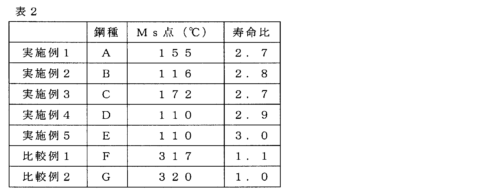
表2及び図1に示すように、実施例1~5において寿命延長効果が認められており、Ms点が173℃以下であれば良いことがわかる。
(試験2)
表3に示すように表1に示す鋼材からなる棒状試験片を用い、この棒状試験片を周波数30~100kHzにて高周波熱処理による移動焼きを施した後、160~200℃で2時間の焼戻し処理を行い、研磨により黒皮表面から4mm除去した後、試験1と同様の寿命試験に供した。また、下記式2からDI値を算出した。結果を表3及び図3に示すが、比較例3に対する相対値(寿命比)で示す。
式2=(0.2[C]+0.14)×(0.64[Si]+1)×(4・1[Mn]+1)×(2.33[Cr]+1)×(3.14[Mo]+1)×(0.52[Ni]+1)
表3に示すように表1に示す鋼材からなる棒状試験片を用い、この棒状試験片を周波数30~100kHzにて高周波熱処理による移動焼きを施した後、160~200℃で2時間の焼戻し処理を行い、研磨により黒皮表面から4mm除去した後、試験1と同様の寿命試験に供した。また、下記式2からDI値を算出した。結果を表3及び図3に示すが、比較例3に対する相対値(寿命比)で示す。
式2=(0.2[C]+0.14)×(0.64[Si]+1)×(4・1[Mn]+1)×(2.33[Cr]+1)×(3.14[Mo]+1)×(0.52[Ni]+1)
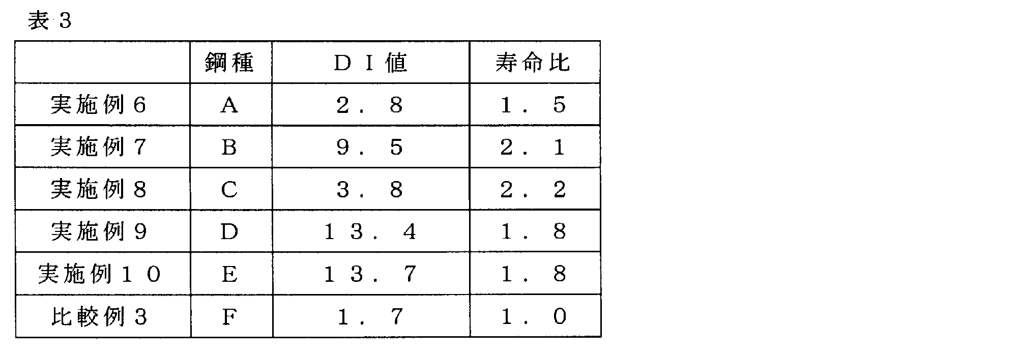
表3及び図2に示すように、実施例6~10において寿命延長効果が認められており、DI値が2.8以上であれば良いことがわかる。また、実施例6と実施例8とはほぼ同じDI値であるが、実施例8の方が寿命が延びている。これは、4mmの取り代位置において、両者の品質の差異が生じたことに起因していると考えられる。即ち、実施例6では鋼材A(Ms点155℃)、実施例8では鋼材C(Ms点172℃)を使用しており、寿命延長効果には、一定水準以上の熱処理品質を得ることが必要であり、DI値とMs点との両方の影響を受けることがわかる。
(試験3)
表4に示すように表1に示す鋼材からなる棒状試験片を用い、高周波熱処理し、溝加工を施してねじ軸を作製した。そして、作製したねじ軸の軌道面表面の硬さ及び表面残留オーステナイト量を測定した。また、作製したねじ軸を用いてボールねじ装置を作製し、試験1と同様の寿命試験に供した。結果を表4に示すが、比較例6に対する相対値(寿命比)で示す。また、寿命比と、表面残留オーステナイト量との関係を図3にグラフ化して示す。
表4に示すように表1に示す鋼材からなる棒状試験片を用い、高周波熱処理し、溝加工を施してねじ軸を作製した。そして、作製したねじ軸の軌道面表面の硬さ及び表面残留オーステナイト量を測定した。また、作製したねじ軸を用いてボールねじ装置を作製し、試験1と同様の寿命試験に供した。結果を表4に示すが、比較例6に対する相対値(寿命比)で示す。また、寿命比と、表面残留オーステナイト量との関係を図3にグラフ化して示す。

比較例6で用いた鋼材Gは、高周波熱処理による表面残留オーステナイト量を高めることは難しく、寿命延長効果は認められない。これに対し実施例11~39で用いた鋼材A,B,C,D,Eでは、高周波熱処理における出力を高めることにより、表面残留オーステナイト量を高くすることができ、9.7体積%以上にすることにより十分な寿命延長効果が得られ、13体積%以上にすることが好ましいことがわかる。
また、表面残留オーステナイト量が13体積%以上の範囲において、寿命にバラつきが見られる。検討の結果、表面残留オーステナイトと硬さ(HRC)との間に相関があることを見出した。図4に、比較例、並びに寿命比が1.6以上となる実施例について、それぞれの硬さと表面残留オーステナイト量との関係をグラフ化して示す。
更に、表面残留オーステナイトと硬さ(HRC)とで表される式3または式4と、寿命比との間にも相関があることを見出した。式3の値及び式4の値を表4に併記するとともに、式3の値と寿命比との関係を図5に、式4と寿命比との関係を図6にそれぞれグラフ化して示す。図示されるように、式3の値及び式4の値とも0以上で、寿命延長効果が得られている。式3及び式4を表面残留オーステナイトに関する関係式に変換し、それぞれを図4に直線で示すが、プロット「×」で示す比較例は、何れも式3または式4に関する2本の直線で囲まれた領域の範囲外にある。即ち、寿命延長には、式3と式4とを同時に満足することが好ましい。
(試験4)
表5に示すように表1に示す鋼材からなる棒状試験片を用い、高周波熱処理して有効硬化層の割合の異なるねじ軸を作製した。作製したねじ軸について、有効硬化層の割合(%)、とともに、表面残留オーステナイト量(体積%)及び平均残留オーステナイト量(体積%)を測定した。尚、表面残留オーステナイト量とは、軌道面表面から50μm深さにおける残留オーステナイト量であり、軌道面表面から50μm分表層を取り除いた後、X線により測定した。また、芯部(硬さHv500未満の領域)について化学分析して金属組織を求めた。更に、高周波熱処理後、再度低温で所定時間焼戻しを行う前後で、軸方向の寸法変化率を測定し、比較例9に対する相対値(寸法変化率比)を求めた。それぞれの結果を表5に併記するとともに、図7に有効硬化層割合と軸方向の寸法変化率との関係をグラフ化して示す。
表5に示すように表1に示す鋼材からなる棒状試験片を用い、高周波熱処理して有効硬化層の割合の異なるねじ軸を作製した。作製したねじ軸について、有効硬化層の割合(%)、とともに、表面残留オーステナイト量(体積%)及び平均残留オーステナイト量(体積%)を測定した。尚、表面残留オーステナイト量とは、軌道面表面から50μm深さにおける残留オーステナイト量であり、軌道面表面から50μm分表層を取り除いた後、X線により測定した。また、芯部(硬さHv500未満の領域)について化学分析して金属組織を求めた。更に、高周波熱処理後、再度低温で所定時間焼戻しを行う前後で、軸方向の寸法変化率を測定し、比較例9に対する相対値(寸法変化率比)を求めた。それぞれの結果を表5に併記するとともに、図7に有効硬化層割合と軸方向の寸法変化率との関係をグラフ化して示す。

実施例38~45では、有効硬化層の割合が増加しても軸方向の寸法が殆ど変化しない。これに対し比較例7~9では、有効硬化層の割合が増加するのに伴い軸方向の寸法も増加している。実施例は何れも有効硬化層の割合が60%以下であり、有効硬化層の割合を60%以下にすることにより、寸法安定性に優れるようになることがわかる。
また、比較例9は、現行のボールねじ装置のねじ軸を模したものであるが、表面残留オーステナイト量が少ないのにも関わらず、実施例38~45と同等の寸法変化量になっている。このことから、平均残留オーステナイト量を4.5体積%以下にすることも寸法安定性に有効であるといえる。
更に、実施例38~45では表面残留オーステナイト量が5~40体積%であり、寸法変化率が小さい。このことから、表面残留オーステナイト量を5~40体積%にすることも有効であるといえる。
尚、芯部の化学分析の結果、比較例9以外は、何れもフェライト相とセメンタイト相とからなるパーライトであった。
(試験5)
表6に示すように表1に示す鋼材からなる棒状素材(直径12.8mm)を用い、長手方向中央部の円周上に1.5Rの溝を形成した。溝深さは1.5mmであり、溝の幅は3mmである。その後、周波数10~30kHzにて高周波熱処理してねじ軸を作製した。作製したねじ軸について、溝底の炭化物面積率及び旧オーステナイトの結晶粒径を測定した。結果を表6に併記する。
表6に示すように表1に示す鋼材からなる棒状素材(直径12.8mm)を用い、長手方向中央部の円周上に1.5Rの溝を形成した。溝深さは1.5mmであり、溝の幅は3mmである。その後、周波数10~30kHzにて高周波熱処理してねじ軸を作製した。作製したねじ軸について、溝底の炭化物面積率及び旧オーステナイトの結晶粒径を測定した。結果を表6に併記する。
また、作製したねじ軸を4点曲げ試験に供し、抗折強度を測定した。結果を表6に併記するが、現行品を模した比較例10に対する相対値(抗折強度比)として示す。また、図8に溝底の炭化物面積率と抗折硬度比との関係をグラフ化して示す。尚、何れのねじ軸でも、溝底から亀裂が発生すると同時に、その亀裂は停止することなく、ねじ軸の破断に至ることを確認した。

比較例10は現行の鋼材を使用して、現行と同様の品質を模したものであるが、比較例11は、この比較例10よりも抗折強度が低下している。比較例11では、高周波熱処理において設定出力を高めにして炭素の溶け込み量を多くしており、マトリックスの変形能が低下したことが原因である。
実施例46~56では、比較例11よりも設定出力を低くしており、現行の比較例10と同等以上の抗折強度を有している。抗折硬度は一般に、硬さが低下するほど高くなる傾向にあるが、本発明のように高炭素鋼を用いる場合、比較例11のように炭素の溶け込み量が多くなると柔らかい組織である残留オーステナイト量が多くなり、結果として硬さが低下するため、評価指標としては適さない。妥当な評価指標としては、マルテンサイト中の炭素の固溶量であるが、その固溶量を定量的に測定することは簡便ではない。本発明では、軸受鋼を用いるため、固溶炭素量は素材の炭素量から固溶していない炭素量、即ち残存炭化物量を差し引くことにより求めることができる。残存炭化物量が多い、即ち固溶炭素量が少ない状態において抗折強度が向上し、実施例46~56から溝底での炭化物の面積率が1.5%以上において現行と同等以上の抗折強度が得られることがわかる。
また、抗折強度と旧オーステナイト粒径との相関を調べたところ、比較例11と実施例46~56との比較から、溝底における旧オーステナイトの粒径を30μm以下にすることが好ましいといえる。
更に、これらの結果から、溝底の炭化物面積率と旧オーステナイト粒径とに関する下記式5の値と、抗折強度比との間に相関があることを見出した。式5の値を表6に併記するとともに、抗折強度比との関係をグラフ化して図9に示すが、式5の値が22以上、好ましくは35以上であるときに、抗折強度比を大きくすることできる。
式5=溝底の炭化物面積率+50-旧オーステナイト粒径
式5=溝底の炭化物面積率+50-旧オーステナイト粒径
(試験6)
上記試験結果を基に、ボールねじ装置BS6316-10.5(呼び:JIS B1192 63×16×300-Ct7)を作製し、日本精工株式会社製のボールねじ耐久試験機に装着して耐久性試験を行った。試験条件は下記の通りである。また、実施例57~61では高周波熱処理を行い、実施例62及び比較例12では浸炭処理を行ってエンリッチガスの量を調整することにより、軌道面の水素量に調整した。水素量は、試験前のねじ軸の軌道面を切断し、10mm四方の直立方体の上面が軌道面となる立体を形成した後、室温から400℃まで加熱して放出させた水素の総量を水素分析装置により測定した値である。寿命は、鋼材Gからなるねじ軸を用いたボールねじ装置の計算寿命に対する相対値(寿命比)で示す。結果を表7に示す。また、表7には、この水素量とともに、作製したねじ軸のDI値、Ms点及び表面残留オーステナイト量を併記する。更に、図10に水素量と寿命比との関係をグラフ化して示す。
<試験条件>
・ねじ軸の外径:63mm
・リード:16mm
・ボールの直径:12.7mm
・試験荷重:300kN
・最高回転速度:3200min-1(Dn:20万)
・ナットの素材:SCM420
・セパレータの材質:66ナイロン
・循環方式:リターンチューブ方式
・潤滑剤:リューベ株式会社製「YS2グリース」
上記試験結果を基に、ボールねじ装置BS6316-10.5(呼び:JIS B1192 63×16×300-Ct7)を作製し、日本精工株式会社製のボールねじ耐久試験機に装着して耐久性試験を行った。試験条件は下記の通りである。また、実施例57~61では高周波熱処理を行い、実施例62及び比較例12では浸炭処理を行ってエンリッチガスの量を調整することにより、軌道面の水素量に調整した。水素量は、試験前のねじ軸の軌道面を切断し、10mm四方の直立方体の上面が軌道面となる立体を形成した後、室温から400℃まで加熱して放出させた水素の総量を水素分析装置により測定した値である。寿命は、鋼材Gからなるねじ軸を用いたボールねじ装置の計算寿命に対する相対値(寿命比)で示す。結果を表7に示す。また、表7には、この水素量とともに、作製したねじ軸のDI値、Ms点及び表面残留オーステナイト量を併記する。更に、図10に水素量と寿命比との関係をグラフ化して示す。
<試験条件>
・ねじ軸の外径:63mm
・リード:16mm
・ボールの直径:12.7mm
・試験荷重:300kN
・最高回転速度:3200min-1(Dn:20万)
・ナットの素材:SCM420
・セパレータの材質:66ナイロン
・循環方式:リターンチューブ方式
・潤滑剤:リューベ株式会社製「YS2グリース」
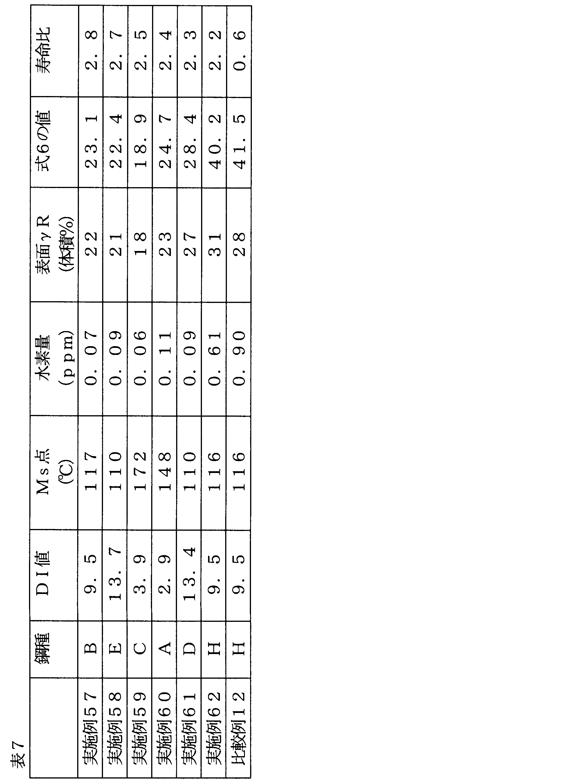
表7に示すように、実施例57~62は、Ms点が173℃以下、DI値が2.8以上、表面残留オーステナイト量が5~40体積%であり、更に、軌道面の水素量が0.61ppm以下であり、何れも計算寿命に対して2倍以上の寿命を有する。
また、軌道面の水素量と表面残留オーステナイトで表される式6の値と、寿命比との間に相関があることを見出した。表7に式6の値を併記するとともに、図11に式6の値と寿命比との関係をグラフ化して示すが、式6の値が40.2以下であれば寿命比を大きく延長させることができる。
式6=(軌道面の水素量)×15+表面残留オーステナイト量
式6=(軌道面の水素量)×15+表面残留オーステナイト量
本発明を詳細にまた特定の実施態様を参照して説明したが、本発明の精神と範囲を逸脱することなく様々な変更や修正を加えることができることは当業者にとって明らかである。
本出願は、2014年5月30日出願の日本特許出願(特願2014-112386)、2014年6月10日出願の日本特許出願(特願2014-119697)、2014年11月4日出願の日本特許出願(特願2014-224033)、2015年1月26日出願の日本特許出願(特願2015-012610)、2015年1月27日出願の日本特許出願(特願2015-013626)に基づくものであり、その内容はここに参照として取り込まれる。
本出願は、2014年5月30日出願の日本特許出願(特願2014-112386)、2014年6月10日出願の日本特許出願(特願2014-119697)、2014年11月4日出願の日本特許出願(特願2014-224033)、2015年1月26日出願の日本特許出願(特願2015-012610)、2015年1月27日出願の日本特許出願(特願2015-013626)に基づくものであり、その内容はここに参照として取り込まれる。
本発明のボールねじ装置は、これまでよりも優れた寸法安定性、白色はく離を含めたはく離への耐性及び耐摩耗性を備えるため、特に射出成形機用のボールねじ装置に有用であり、高性能で長寿命となる。
Claims (3)
- 外周面に螺旋溝を有するねじ軸と、前記ねじ軸の螺旋溝に対向する螺旋溝を内周面に有するボールナットと、前記両螺旋溝間に介挿されるとともにボールナットに設けたボール循環路によって循環可能とされた複数個のボールとを備えるボールねじ装置において、
前記ねじ軸が、高炭素軸受鋼または下記式1で算出されるMs点が172℃以下で下記式2で算出されるDI値が2.8以上である鋼材を熱硬化処理してなり、かつ、
径方向断面における硬さがHV500以上である有効硬化層の割合が60%以下、
硬さがHV500未満である非硬化層がフェライト相及びセメンタイト相を含有する金属組織であり、
径方向断面における平均残留オーステナイト量が4.5%以下であり、
螺旋溝の転動面の水素量が0.61ppm以下であり、
溝底の炭化物面積率が1.5%以上であり、
軌道面から深さ50μmでの残留オーステナイト量が5~40体積%
であることを特徴とするボールねじ装置。
式1=550-361[C]-39[Mn]-20[Cr]-17[Ni]-5[Mo]
式2=(0.2[C]+0.14)×(0.64[Si]+1)×(4.1[Mn]+1)×(2.33[Cr]+1)×(3.14[Mo]+1)×(0.52[Ni]+1)
(式中、[C]、[Si]、[Mn]、[Cr]、[Mo]、[Ni]は、鋼材中のC、Si、Mn、Cr、Mo、Niの各含有量(質量%)である。) - 前記ねじ軸の軌道面表面の硬さ(HRC)及び軌道面から深さ50μmでの残留オーステナイト量(γR)が、下記式3及び式4を満足することを特徴とする請求項1記載のボールねじ装置。
式3:γR+0.15×HRC-19.1≧0
式4:γR+21.2×HRC-1176≧0 - 前記ねじ軸の溝底の旧オーステナイト粒径が30μm以下であることを特徴とする請求項1または2記載のボールねじ装置。
Priority Applications (1)
| Application Number | Priority Date | Filing Date | Title |
|---|---|---|---|
| JP2016523590A JPWO2015182767A1 (ja) | 2014-05-30 | 2015-05-29 | ボールねじ装置 |
Applications Claiming Priority (10)
| Application Number | Priority Date | Filing Date | Title |
|---|---|---|---|
| JP2014112386 | 2014-05-30 | ||
| JP2014-112386 | 2014-05-30 | ||
| JP2014119697 | 2014-06-10 | ||
| JP2014-119697 | 2014-06-10 | ||
| JP2014224033 | 2014-11-04 | ||
| JP2014-224033 | 2014-11-04 | ||
| JP2015-012610 | 2015-01-26 | ||
| JP2015012610 | 2015-01-26 | ||
| JP2015-013626 | 2015-01-27 | ||
| JP2015013626 | 2015-01-27 |
Publications (1)
| Publication Number | Publication Date |
|---|---|
| WO2015182767A1 true WO2015182767A1 (ja) | 2015-12-03 |
Family
ID=54699081
Family Applications (3)
| Application Number | Title | Priority Date | Filing Date |
|---|---|---|---|
| PCT/JP2015/065638 Ceased WO2015182764A1 (ja) | 2014-05-30 | 2015-05-29 | ボールねじ装置 |
| PCT/JP2015/065645 Ceased WO2015182767A1 (ja) | 2014-05-30 | 2015-05-29 | ボールねじ装置 |
| PCT/JP2015/065632 Ceased WO2015182761A1 (ja) | 2014-05-30 | 2015-05-29 | ボールねじ装置 |
Family Applications Before (1)
| Application Number | Title | Priority Date | Filing Date |
|---|---|---|---|
| PCT/JP2015/065638 Ceased WO2015182764A1 (ja) | 2014-05-30 | 2015-05-29 | ボールねじ装置 |
Family Applications After (1)
| Application Number | Title | Priority Date | Filing Date |
|---|---|---|---|
| PCT/JP2015/065632 Ceased WO2015182761A1 (ja) | 2014-05-30 | 2015-05-29 | ボールねじ装置 |
Country Status (3)
| Country | Link |
|---|---|
| JP (3) | JPWO2015182767A1 (ja) |
| TW (3) | TW201608152A (ja) |
| WO (3) | WO2015182764A1 (ja) |
Cited By (1)
| Publication number | Priority date | Publication date | Assignee | Title |
|---|---|---|---|---|
| JP2018054112A (ja) * | 2016-09-30 | 2018-04-05 | 日本精工株式会社 | ねじ装置 |
Families Citing this family (2)
| Publication number | Priority date | Publication date | Assignee | Title |
|---|---|---|---|---|
| DE102023109536A1 (de) * | 2023-04-17 | 2024-10-17 | Stabilus Gmbh | Spindelantriebseinrichtung |
| CN117387459B (zh) * | 2023-12-08 | 2024-02-27 | 天津德科智控股份有限公司 | 一种滚珠螺母内螺纹滚道加工精度的定性测量检具 |
Citations (4)
| Publication number | Priority date | Publication date | Assignee | Title |
|---|---|---|---|---|
| JP2004076823A (ja) * | 2002-08-13 | 2004-03-11 | Nsk Ltd | 転動装置 |
| JP2005299720A (ja) * | 2004-04-07 | 2005-10-27 | Ntn Corp | 自動車用ボールねじ |
| JP2010090924A (ja) * | 2008-10-03 | 2010-04-22 | Thk Co Ltd | ボールねじ |
| JP2010255702A (ja) * | 2009-04-23 | 2010-11-11 | Nagato:Kk | 転動溝付き軸部品 |
Family Cites Families (11)
| Publication number | Priority date | Publication date | Assignee | Title |
|---|---|---|---|---|
| JPH10259451A (ja) * | 1997-01-20 | 1998-09-29 | Nippon Seiko Kk | 転がり軸受 |
| JP2000326856A (ja) * | 1999-05-18 | 2000-11-28 | Ntn Corp | 電動式パワーステアリング装置 |
| JP3975314B2 (ja) * | 1999-08-27 | 2007-09-12 | 株式会社ジェイテクト | 軸受部品素材及び転がり軸受の軌道輪の製作方法 |
| JP2004115903A (ja) * | 2002-09-30 | 2004-04-15 | Ntn Corp | ボールねじ部品およびボールねじ |
| JP4121393B2 (ja) * | 2003-02-25 | 2008-07-23 | 株式会社ジェイテクト | ねじ軸、ねじ軸の硬化方法およびボールねじ |
| JP2005155714A (ja) * | 2003-11-21 | 2005-06-16 | Nsk Ltd | ボールねじ |
| JP2005240970A (ja) * | 2004-02-27 | 2005-09-08 | Nsk Ltd | ねじ装置 |
| JP2006083988A (ja) * | 2004-09-17 | 2006-03-30 | Nsk Ltd | ボールねじ |
| JP5130886B2 (ja) * | 2007-12-03 | 2013-01-30 | 日本精工株式会社 | 転がりねじ装置及びその製造方法 |
| JP2009204036A (ja) * | 2008-02-27 | 2009-09-10 | Nsk Ltd | ボールねじ装置 |
| JP6040700B2 (ja) * | 2012-10-23 | 2016-12-07 | 日本精工株式会社 | 転がり軸受 |
-
2015
- 2015-05-29 TW TW104117500A patent/TW201608152A/zh unknown
- 2015-05-29 WO PCT/JP2015/065638 patent/WO2015182764A1/ja not_active Ceased
- 2015-05-29 JP JP2016523590A patent/JPWO2015182767A1/ja active Pending
- 2015-05-29 TW TW104117499A patent/TWI575171B/zh not_active IP Right Cessation
- 2015-05-29 JP JP2016523585A patent/JPWO2015182761A1/ja active Pending
- 2015-05-29 WO PCT/JP2015/065645 patent/WO2015182767A1/ja not_active Ceased
- 2015-05-29 WO PCT/JP2015/065632 patent/WO2015182761A1/ja not_active Ceased
- 2015-05-29 TW TW104117497A patent/TWI575170B/zh not_active IP Right Cessation
- 2015-05-29 JP JP2016523587A patent/JP6044744B2/ja active Active
Patent Citations (4)
| Publication number | Priority date | Publication date | Assignee | Title |
|---|---|---|---|---|
| JP2004076823A (ja) * | 2002-08-13 | 2004-03-11 | Nsk Ltd | 転動装置 |
| JP2005299720A (ja) * | 2004-04-07 | 2005-10-27 | Ntn Corp | 自動車用ボールねじ |
| JP2010090924A (ja) * | 2008-10-03 | 2010-04-22 | Thk Co Ltd | ボールねじ |
| JP2010255702A (ja) * | 2009-04-23 | 2010-11-11 | Nagato:Kk | 転動溝付き軸部品 |
Cited By (1)
| Publication number | Priority date | Publication date | Assignee | Title |
|---|---|---|---|---|
| JP2018054112A (ja) * | 2016-09-30 | 2018-04-05 | 日本精工株式会社 | ねじ装置 |
Also Published As
| Publication number | Publication date |
|---|---|
| TWI575171B (zh) | 2017-03-21 |
| WO2015182761A1 (ja) | 2015-12-03 |
| WO2015182764A1 (ja) | 2015-12-03 |
| JPWO2015182764A1 (ja) | 2017-04-20 |
| JPWO2015182761A1 (ja) | 2017-04-20 |
| TW201608154A (zh) | 2016-03-01 |
| JP6044744B2 (ja) | 2016-12-14 |
| TWI575170B (zh) | 2017-03-21 |
| TW201608153A (zh) | 2016-03-01 |
| JPWO2015182767A1 (ja) | 2017-04-20 |
| TW201608152A (zh) | 2016-03-01 |
Similar Documents
| Publication | Publication Date | Title |
|---|---|---|
| US9394583B2 (en) | Rolling bearing | |
| CN103237913B (zh) | 滚动轴承及其制造方法 | |
| JP2014020538A (ja) | 転がり軸受、転がり軸受の製造方法、高周波熱処理装置 | |
| JP2008223104A (ja) | 転動軸 | |
| JP2015042897A (ja) | ボールねじのねじ軸の製造方法、ボールねじ | |
| JP5298683B2 (ja) | 転がり軸受及びその製造方法 | |
| KR20240012362A (ko) | 궤도륜 및 샤프트 | |
| WO2015182767A1 (ja) | ボールねじ装置 | |
| JP2010025311A (ja) | 転がり軸受及びその製造方法 | |
| JP2005273759A (ja) | 転がり支持装置、転がり支持装置の構成部品の製造方法、鋼の熱処理方法 | |
| JP2005282854A (ja) | 転がり軸受 | |
| JP2015218746A (ja) | 転動軸 | |
| JP6238124B2 (ja) | 水素脆性型の面疲労強度に優れた浸炭窒化鋼及びそれを用いた浸炭窒化部品 | |
| JP5168898B2 (ja) | 転動軸 | |
| JP5668283B2 (ja) | 転がり摺動部材の製造方法 | |
| JP5879681B2 (ja) | 転動軸の製造方法 | |
| JP2013221207A (ja) | 転動軸 | |
| JP2005290496A (ja) | 転動部品および転がり軸受 | |
| JP6658143B2 (ja) | 転がり摺動部材及び転がり軸受 | |
| JP4534537B2 (ja) | 転がり軸受 | |
| JP6881496B2 (ja) | 部品およびその製造方法 | |
| JP2006329268A (ja) | プラネタリギヤ機構用転がり軸受 | |
| JP2007024250A (ja) | ピニオンシャフト | |
| WO2023026621A1 (ja) | 転がり軸受 | |
| JP2017002359A (ja) | 転動軸の製造方法 |
Legal Events
| Date | Code | Title | Description |
|---|---|---|---|
| 121 | Ep: the epo has been informed by wipo that ep was designated in this application |
Ref document number: 15799297 Country of ref document: EP Kind code of ref document: A1 |
|
| ENP | Entry into the national phase |
Ref document number: 2016523590 Country of ref document: JP Kind code of ref document: A |
|
| NENP | Non-entry into the national phase |
Ref country code: DE |
|
| 122 | Ep: pct application non-entry in european phase |
Ref document number: 15799297 Country of ref document: EP Kind code of ref document: A1 |