WO2015159571A1 - 鞍乗型車両のラジエータ - Google Patents
鞍乗型車両のラジエータ Download PDFInfo
- Publication number
- WO2015159571A1 WO2015159571A1 PCT/JP2015/053054 JP2015053054W WO2015159571A1 WO 2015159571 A1 WO2015159571 A1 WO 2015159571A1 JP 2015053054 W JP2015053054 W JP 2015053054W WO 2015159571 A1 WO2015159571 A1 WO 2015159571A1
- Authority
- WO
- WIPO (PCT)
- Prior art keywords
- radiator
- fan
- core
- cooling fan
- cooling
- Prior art date
- Legal status (The legal status is an assumption and is not a legal conclusion. Google has not performed a legal analysis and makes no representation as to the accuracy of the status listed.)
- Ceased
Links
Images

Classifications
-
- B—PERFORMING OPERATIONS; TRANSPORTING
- B62—LAND VEHICLES FOR TRAVELLING OTHERWISE THAN ON RAILS
- B62J—CYCLE SADDLES OR SEATS; AUXILIARY DEVICES OR ACCESSORIES SPECIALLY ADAPTED TO CYCLES AND NOT OTHERWISE PROVIDED FOR, e.g. ARTICLE CARRIERS OR CYCLE PROTECTORS
- B62J41/00—Arrangements of radiators, coolant hoses or pipes on cycles
-
- B—PERFORMING OPERATIONS; TRANSPORTING
- B60—VEHICLES IN GENERAL
- B60K—ARRANGEMENT OR MOUNTING OF PROPULSION UNITS OR OF TRANSMISSIONS IN VEHICLES; ARRANGEMENT OR MOUNTING OF PLURAL DIVERSE PRIME-MOVERS IN VEHICLES; AUXILIARY DRIVES FOR VEHICLES; INSTRUMENTATION OR DASHBOARDS FOR VEHICLES; ARRANGEMENTS IN CONNECTION WITH COOLING, AIR INTAKE, GAS EXHAUST OR FUEL SUPPLY OF PROPULSION UNITS IN VEHICLES
- B60K11/00—Arrangement in connection with cooling of propulsion units
- B60K11/02—Arrangement in connection with cooling of propulsion units with liquid cooling
- B60K11/04—Arrangement or mounting of radiators, radiator shutters, or radiator blinds
-
- B—PERFORMING OPERATIONS; TRANSPORTING
- B62—LAND VEHICLES FOR TRAVELLING OTHERWISE THAN ON RAILS
- B62J—CYCLE SADDLES OR SEATS; AUXILIARY DEVICES OR ACCESSORIES SPECIALLY ADAPTED TO CYCLES AND NOT OTHERWISE PROVIDED FOR, e.g. ARTICLE CARRIERS OR CYCLE PROTECTORS
- B62J17/00—Weather guards for riders; Fairings or stream-lining parts not otherwise provided for
- B62J17/10—Ventilation or air guiding devices forming part of fairings
-
- B—PERFORMING OPERATIONS; TRANSPORTING
- B62—LAND VEHICLES FOR TRAVELLING OTHERWISE THAN ON RAILS
- B62J—CYCLE SADDLES OR SEATS; AUXILIARY DEVICES OR ACCESSORIES SPECIALLY ADAPTED TO CYCLES AND NOT OTHERWISE PROVIDED FOR, e.g. ARTICLE CARRIERS OR CYCLE PROTECTORS
- B62J23/00—Other protectors specially adapted for cycles
Definitions
- the present invention relates to a radiator that is mounted on a straddle-type vehicle such as a motorcycle and radiates heat from an engine coolant.
- Patent Document 1 As a radiator mounted on a saddle riding type vehicle such as a motorcycle, an electric fan disposed close to the radiator heat dissipation core from the downstream side of the traveling wind and a shroud covering the electric fan are provided. There exists a thing of a structure (for example, patent document 1).
- the shroud of Patent Document 1 covers the electric fan from the downstream side of the traveling wind and also covers the electric fan from the upper side to the both sides and opens downward.
- An object of the present invention is to provide a radiator for a saddle-ride type vehicle in which heat dissipation efficiency does not decrease by preventing the exhaust air that has passed through the fan of the radiator and discharged to the lower side of the fan from flowing backward to the front of the core of the radiator. is there.
- a radiator of a saddle riding type vehicle is a radiator that dissipates heat from a cooling medium of a prime mover mounted on the saddle riding type vehicle, and a core through which the cooling medium flows and a downstream thereof
- a cooling fan disposed on the side and ventilating the core; a fan cover that covers the upper side, both sides, and the downstream side of the cooling fan; and opens downward; and a space between the lower part of the core and the lower part of the cooling fan And a partition wall that suppresses the exhaust air from the opening from flowing back to the core.
- the partition wall protrudes downward from the core. According to this configuration, since the exhaust air is reliably prevented from flowing downwardly of the radiator, it is possible to more efficiently prevent a part of the exhaust air from flowing backward to the front of the radiator.
- the outer diameter D of the cooling fan is substantially the same as the vertical length H of the core, and the protruding length P of the fan cover downward from the core is the vertical length H of the core. Is preferably 0.1 to 0.3 times.
- the fan outer diameter D is increased so as to be substantially the same as the length H of the core. Therefore, even when the traveling wind cannot be used sufficiently, such as when driving at low speed or when stopping, The heat radiation efficiency can be improved by introducing air to the part. Further, since the protrusion length P is set to 0.1 to 0.3H, the size of the fan cover does not become larger than necessary.
- the size of the entire radiator including the fan cover is suppressed, and the fan cover can be smoothly smoothed while suppressing the speed of exhaust air from the cooling fan of the radiator from being reduced by friction loss with the fan cover inner surface. It can be discharged from the opening below.
- the exhaust air is downstream in the radially inner side of the cooling fan so as to guide the exhaust air to the outer periphery of the fan housing of the cooling fan in the fan proximity region of the partition wall facing the outer periphery of the cooling fan.
- the guide part which inclines to the side is formed.
- the inclination angle ⁇ of the guide portion with respect to the front surface of the cooling fan is, for example, 30 to 60 °. According to this configuration, the exhaust air can be guided to the outer periphery of the fan housing of the cooling fan along the guide portion, and the exhaust air guided to the outer periphery of the fan housing does not pass through the cooling fan again. It can be quickly discharged from the lower opening of the cover.
- the guide portion is provided to face an outer periphery of a lower half of the cooling fan. According to this configuration, it is possible to suppress the exhaust air discharged downward from the cooling fan from flowing backward to the front of the core while miniaturizing the fan cover as much as possible.
- the fan cover is attached to the core via an attachment piece, and the fan cover, the partition wall, and the attachment piece are integrally formed. According to this configuration, the handleability is improved by reducing the number of parts, and the fan cover can be easily attached to the core.
- a rear wall that covers the cooling fan from the downstream side is orthogonal to the axis of the cooling fan.
- the fan outlet space Since the dimension of the upper part in the axial direction, that is, the depth of the upper part of the fan cover increases, the upper part of the core is sufficiently ventilated to improve the heat radiation efficiency.
- the fan cover has a generally inverted U shape with a narrow upper portion and a wide lower portion as viewed from the axial center of the cooling fan. According to this configuration, the fan outlet space that extends in the width direction from the upper side to the lower side is formed, so that the downward air discharge becomes smooth.
- FIG. 1 is a side view showing a front half portion of a motorcycle including a radiator according to a preferred embodiment of the present invention. It is the front view which looked at the same radiator from the front side. It is a longitudinal cross-sectional view of the same radiator. It is the rear view which looked at the same radiator from the back side. It is a top view of the same radiator. It is a bottom view of the same radiator. It is the side view which looked at the same radiator from the left side of the body. It is the side view which looked at the same radiator from the right side of a vehicle body.
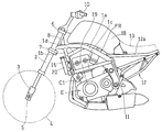
- FIG. 1 shows a front half of a motorcycle to which a radiator according to a preferred embodiment of the present invention is applied.
- the motorcycle of the present invention has a main frame 1 that forms the front half of the vehicle body frame FR and a rear frame 12 that forms the rear half.
- a front fork 2 is supported at the front end of the main frame 1, and a front wheel 4 is supported via an axle 5 on a bottom case 3 provided at the lower end of the front fork 2.
- the front fork 2 is rotatably supported by a head pipe 8 at the front end of the main frame 1 together with an upper bracket 6 and a lower bracket 7 that support the front fork 2, and a handle 10 is attached to the upper bracket 6.
- a swing arm bracket 11 is fixed to the lower portion of the rear end of the main frame 1, and a swing arm that supports a rear wheel (not shown) is pivotally supported by the swing arm bracket 11 so as to be swingable.
- An engine E which is a prime mover for driving the rear wheels, is supported at the lower center of the main frame 1.
- the main frame 1 has a pair of left and right first frame pieces 1a, 1a that extend in the front-rear direction and then bend and extend downward.
- the upper end of the main frame 1 is joined to the rear of the head pipe 8 at the front part of the first frame piece 1a.
- a pair of left and right fourth frame pieces 1d having both ends joined to an intermediate portion in the vertical direction of 1b and 1b and a front portion of an intermediate bent portion of the first frame piece 1a are provided.
- the rear frame 12 has a pair of left and right seat rails 12a connected to the first frame pieces 1a, 1a at an upper portion thereof, and a rider's seat 13 and a passenger's rear seat (not shown) are attached to the seat rails 12a. And are supported.
- a radiator 15 that dissipates the cooling medium of the engine E is attached to the front of the main frame 1 diagonally above and behind the front wheels 4.
- the cooling medium is, for example, cooling water.
- the radiator 15 has a forward leaning posture with its upper end positioned forward of the lower end, and is inclined 10 to 20 ° with respect to the vertical direction in an empty state, and 15 ° in FIG. .
- the inclined radiator 15 is parallel to the second frame piece 1b and the cylinder axis C1 of the engine E in a side view.
- a fuel tank 18 is supported at the upper part of the main frame 1, that is, at the upper part of the vehicle body, between the head pipe 8 and the rider seat 13.
- FIGS. show a state in which the cooling fan 28 and the fan cover 30 are assembled to the radiator 15.
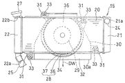
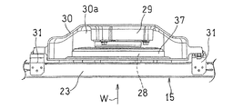
- 2 and 3 are a front view and a longitudinal sectional view of the radiator 15, respectively.
- the radiator 15 has a horizontally long rectangular shape when viewed from the front, and has a core 20 that allows a cooling medium to flow horizontally in a plurality of horizontal fins.
- a cooling medium introduction tank 21 is provided at the right end (left side of the vehicle body) of the core 20, and a cooling medium outlet tank 22 is provided at the left end (right side of the vehicle body). That is, the radiator 15 of this embodiment is a cross flow type.
- the type of the radiator is not limited to this, and for example, the core 20 may be a vertical type in which a cooling medium flows in the vertical direction.
- “left side” and “right side” refer to the left and right sides of the vehicle body, that is, the left and right sides as viewed from the driver who rides the motorcycle.
- the introduction tank 21 introduces a high-temperature cooling medium discharged from the cylinder head 19 of the engine E in FIG. 1 and guides it to the core 20 in FIG.
- a cylindrical cooling medium inlet 21a is provided at the upper end of the introduction tank 21, and an introduction hose 24 for introducing a high-temperature cooling medium from the cylinder head 19 (FIG. 1) is connected to the cooling medium inlet 21a.
- the outlet tank 22 of the radiator 15 guides the coolant that has passed through the core 20 and has become low temperature to the engine E side.
- a cylindrical cooling medium outlet 22a is provided at the lower end of the outlet tank 22, and an outlet hose 25 is connected to the cooling medium outlet 22a.
- a replenishing port 22b for replenishing the cooling medium is provided at the upper end of the lead-out tank 22, and the replenishing port 22b is normally closed with a cap 27.
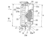
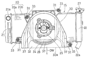
- a cooling fan 28 that ventilates the core 20 and an electric motor 29 that drives the cooling fan 28 are disposed on the back side of the core 20 of the radiator 15.
- the cooling fan 28 is obtained by covering the outer periphery of the rotary blade 36 connected to the electric motor 29 with a fan housing 37, but the fan housing 37 may be omitted.
- the cooling fan 28 and the electric motor 29 are covered with a fan cover 30 having an opening 30a below the upper side, both sides, and the downstream side (rear side).
- a partition wall 32 that partitions the lower portion of the core 20 and the lower portion of the cooling fan 28 is provided radially outward of the front portion of the cooling fan 28.
- the partition wall 32 suppresses the exhaust air DW from the opening 30 a from flowing backward to the core 20.
- the axial position of the front surface of the partition wall 32 substantially matches the front surface of the rotary blade 36 of the cooling fan 28.
- the core 20 is supported by a rectangular frame body 20b that covers the periphery of the plurality of fins when viewed from the front, and the partition wall 32 projects downward from the lower surface of the frame body 20b.
- the fan cover 30 is attached to the frame body 20b of the core 20 by screws through a plurality of attachment pieces 31 provided on the outer periphery thereof.
- the fan cover 30, the partition wall 32, and the attachment piece 31 are made of, for example, resin and are integrally formed by molding.
- the fan cover 30 has a generally inverted U shape with a narrow upper part and a wide lower part as viewed from the direction of the axis C of the cooling fan 28.
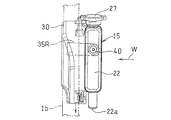
- the introduction tank 21 on the left side of the radiator 15 is attached to the second frame piece 1b on the left side of the main frame 1 via a plate-like left attachment piece 35L.
- the right lead-out tank 22 of the radiator 15 is attached to the right second frame piece 1b via a plate-like right attachment piece 35R.
- the cooling fan 28 is covered with a fan housing 37.
- the electric motor 29 is disposed behind the cooling fan 28, and the cooling fan 28 and the electric motor 29 are covered with a fan cover 30.
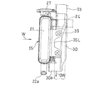
- FIG. 7 which is a side view seen from the left side of the vehicle body
- the left mounting piece 35L is welded to the introduction tank 21 of the radiator 15, and the left mounting piece 35L is connected to the second
- the frame piece 1b is detachably attached.
- FIG. 8 which is a side view seen from the right side of the vehicle body
- a right mounting piece 35R is welded to the right second frame piece 1b, and the right mounting piece 35R is attached to the right side of the radiator 15 by a single screw body 40.
- the lead-out tank 22 is detachably attached.
- a guide portion 34 is formed on the outer periphery of the cooling fan 28 in the partition wall 32, that is, in the fan proximity region close to the outer periphery of the fan housing 37.
- the guide portion 34 is inclined toward the downstream side toward the radially inner side of the cooling fan 28 so as to guide air to the outer periphery of the fan housing 37 of the cooling fan 28.
- the guide portion 34 is provided to face the outer periphery of the lower half of the cooling fan 28.
- the inclination angle ⁇ with respect to the plane orthogonal to the axis C of the guide portion 34, that is, the cooling fan front surface is preferably 30 to 60 °, and more preferably 40 to 50 °.
- the length P projecting downward from the core 20 of the partition wall 32 is 0.1 to 0.3 times, preferably 0.15 to 0.25 times the vertical length H of the core 20.
- the protrusion length P is less than 0.1 times H, a sufficient backflow prevention effect of the exhaust air DW cannot be obtained.
- the protrusion length P is 0.3 times that of H, the effect of preventing the backflow is sufficient, and when it exceeds 0.3 times, the entire radiator 15 including the fan cover becomes larger than necessary.
- the rear wall 30 c on the downstream side of the fan cover 30 that covers the cooling fan 28 from the downstream side is orthogonal to the axis C of the cooling fan 28.
- the radiator 15 is covered with a fan cover 30 that opens downward, on both sides and downstream of the cooling fan 28 that ventilates the core 20. Therefore, the exhaust air DW passing through the core 20 and the cooling fan 28 of the radiator 15 is reliably discharged downward from the lower opening 30a of the fan cover 30. This prevents the rider from being exposed to the exhaust air DW.
- the partition wall 32 protrudes downward from the core 20, the exhaust air DW is reliably prevented from entering the lower portion of the radiator 15, and a part of the exhaust air DW is prevented from flowing backward in front of the radiator 15. It can be blocked more effectively.
- the outer diameter D of the cooling fan 28 is increased so as to be substantially the same as the vertical length H of the core 20, even when the traveling wind W is not sufficiently utilized, such as when traveling at a low speed or when stopping, the core 20 It is possible to improve heat dissipation efficiency by introducing air to the main part. Further, since the length P of the fan cover 30 protruding downward from the core 20 is as short as 0.1 to 0.3 times the vertical length H of the core 20, the fan cover 30 does not become larger than necessary. Therefore, the enlargement of the entire radiator 15 including the fan cover 30 is suppressed.
- the speed of the exhaust air DW from the cooling fan 28 of the radiator 15 is suppressed from decreasing due to loss due to friction with the inner surface of the fan cover 30, and the exhaust air DW is reduced.
- the air can be smoothly discharged from the opening 30a below the fan cover 30.
- a guide portion 34 is formed in a fan proximity region facing the outer periphery of the cooling fan 28 in the partition wall 32, and air is guided along the guide portion 34 to the outer periphery of the fan housing 37 of the cooling fan 28. Therefore, even if the exhaust air DW passes over the partition wall 32 and goes below the core 20, it is guided to the outer periphery of the fan housing 37 together with the air. As a result, the exhaust air DW is quickly discharged from the lower opening 30a of the fan cover 30 without passing through the cooling fan 28 again.
- the guide part 34 is provided facing the outer periphery of the lower half of the cooling fan 28, the exhaust air DW exhausted downward from the cooling fan 28 while the fan cover 30 is miniaturized as much as possible. It is possible to suppress backflowing forward.
- the fan cover 30 is attached to the core 20 via an attachment piece 31, and the fan cover 30, the partition wall 32, and the attachment piece 31 are integrally formed. Thereby, the handleability is improved by reducing the number of parts, and the fan cover 30 can be easily attached to the core 20.
- the rear wall 30c that covers the cooling fan 28 shown in FIG. 3 from the downstream side is orthogonal to the axis C of the cooling fan. Accordingly, the upper portion of the fan outlet space is compared with the case of forming a so-called widening fan outlet space in which the rear wall 30c is inclined backward from the upper side to the lower side in order to smooth the exhaust air DW downward. Therefore, the exhaust wind DW can be smoothly discharged from the lower opening 30 a of the fan cover 30. In addition, the upper portion of the core 20 is sufficiently ventilated, and the heat dissipation efficiency of the radiator 15 is improved.
- the motorcycle is exemplified as the saddle riding type vehicle.
- the present invention can be similarly applied to a saddle riding type vehicle even if it is a three-wheel or four-wheel rough terrain vehicle.
- An electric motor may be used as the prime mover. Therefore, such a thing is also included in the scope of the present invention.
Landscapes
- Engineering & Computer Science (AREA)
- Mechanical Engineering (AREA)
- Chemical & Material Sciences (AREA)
- Combustion & Propulsion (AREA)
- Transportation (AREA)
- Cooling, Air Intake And Gas Exhaust, And Fuel Tank Arrangements In Propulsion Units (AREA)
Priority Applications (2)
| Application Number | Priority Date | Filing Date | Title |
|---|---|---|---|
| EP15780445.1A EP3133007B1 (en) | 2014-04-15 | 2015-02-04 | Radiator for saddled vehicle |
| US15/286,343 US10124662B2 (en) | 2014-04-15 | 2016-10-05 | Radiator for saddled vehicle |
Applications Claiming Priority (2)
| Application Number | Priority Date | Filing Date | Title |
|---|---|---|---|
| JP2014-083378 | 2014-04-15 | ||
| JP2014083378A JP6243282B2 (ja) | 2014-04-15 | 2014-04-15 | 鞍乗型車両のラジエータ |
Related Child Applications (1)
| Application Number | Title | Priority Date | Filing Date |
|---|---|---|---|
| US15/286,343 Continuation US10124662B2 (en) | 2014-04-15 | 2016-10-05 | Radiator for saddled vehicle |
Publications (1)
| Publication Number | Publication Date |
|---|---|
| WO2015159571A1 true WO2015159571A1 (ja) | 2015-10-22 |
Family
ID=54323789
Family Applications (1)
| Application Number | Title | Priority Date | Filing Date |
|---|---|---|---|
| PCT/JP2015/053054 Ceased WO2015159571A1 (ja) | 2014-04-15 | 2015-02-04 | 鞍乗型車両のラジエータ |
Country Status (4)
| Country | Link |
|---|---|
| US (1) | US10124662B2 (enExample) |
| EP (1) | EP3133007B1 (enExample) |
| JP (1) | JP6243282B2 (enExample) |
| WO (1) | WO2015159571A1 (enExample) |
Cited By (6)
| Publication number | Priority date | Publication date | Assignee | Title |
|---|---|---|---|---|
| US11173808B2 (en) | 2016-12-22 | 2021-11-16 | Polaris Industies Inc. | Vehicle |
| US12172518B2 (en) | 2019-04-30 | 2024-12-24 | Polaris Industries Inc. | Vehicle |
| US12187127B2 (en) | 2020-05-15 | 2025-01-07 | Polaris Industries Inc. | Off-road vehicle |
| US12384464B2 (en) | 2020-05-15 | 2025-08-12 | Polaris Industries Inc. | Off-road vehicle |
| US12385429B2 (en) | 2022-06-13 | 2025-08-12 | Polaris Industries Inc. | Powertrain for a utility vehicle |
| US12552246B2 (en) | 2015-05-15 | 2026-02-17 | Polaris Industries Inc. | Utility vehicle |
Families Citing this family (10)
| Publication number | Priority date | Publication date | Assignee | Title |
|---|---|---|---|---|
| JP6437981B2 (ja) * | 2016-10-20 | 2018-12-12 | 本田技研工業株式会社 | 鞍乗型車両 |
| IT201600130142A1 (it) * | 2016-12-22 | 2018-06-22 | Piaggio & C Spa | Sistema di raffreddamento del motore di un motoveicolo |
| US10655536B1 (en) | 2017-05-24 | 2020-05-19 | Indian Motorcycle International, LLC | Engine |
| US10589621B1 (en) | 2017-05-24 | 2020-03-17 | Indian Motorcycle International, LLC | Two-wheeled vehicle |
| JP6689798B2 (ja) * | 2017-08-30 | 2020-04-28 | 本田技研工業株式会社 | 鞍乗り型車両 |
| DE102019115786B4 (de) * | 2019-06-11 | 2021-03-04 | Bayerische Motoren Werke Aktiengesellschaft | Elektromotorrad |
| JP2021160372A (ja) * | 2020-03-30 | 2021-10-11 | 本田技研工業株式会社 | ラジエータ |
| US11674432B2 (en) * | 2020-04-23 | 2023-06-13 | Clark Equipment Company | Identification and reduction of backflow suction in cooling systems |
| CN112208690B (zh) * | 2020-10-13 | 2022-01-25 | 唐山金亨通车料有限公司 | 一种可快速降温自行车坐垫 |
| JP7773853B2 (ja) * | 2020-11-12 | 2025-11-20 | カワサキモータース株式会社 | 鞍乗型車両 |
Citations (4)
| Publication number | Priority date | Publication date | Assignee | Title |
|---|---|---|---|---|
| JP2007532814A (ja) * | 2004-04-08 | 2007-11-15 | ベール ゲーエムベーハー ウント コー カーゲー | 冷却システム |
| JP2008013149A (ja) * | 2006-07-10 | 2008-01-24 | Honda Motor Co Ltd | 車両の導風板 |
| JP2008254463A (ja) * | 2007-03-30 | 2008-10-23 | Honda Motor Co Ltd | 自動2輪車用エンジンの冷却装置 |
| JP2013136273A (ja) * | 2011-12-28 | 2013-07-11 | Kawasaki Heavy Ind Ltd | 鞍乗型車両のラジエータの導風構造 |
Family Cites Families (13)
| Publication number | Priority date | Publication date | Assignee | Title |
|---|---|---|---|---|
| JPS59114178A (ja) * | 1982-12-17 | 1984-07-02 | ヤマハ発動機株式会社 | スク−タ型車輌 |
| JPH01262278A (ja) * | 1988-04-11 | 1989-10-19 | Yamaha Motor Co Ltd | 自動二,三輪車のエンジン冷却装置 |
| JP2002019662A (ja) * | 2000-07-05 | 2002-01-23 | Yamaha Motor Co Ltd | スクータ型車両用フロント側カバー構造 |
| CN101164825A (zh) * | 2006-10-16 | 2008-04-23 | 光阳工业股份有限公司 | 热气导引装置 |
| JP4160105B2 (ja) * | 2007-11-12 | 2008-10-01 | 本田技研工業株式会社 | スクータ型車両用燃料タンクの遮熱構造 |
| US8539929B2 (en) * | 2009-11-18 | 2013-09-24 | Harley-Davidson Motor Company | Cylinder head cooling system |
| JP2011173484A (ja) * | 2010-02-24 | 2011-09-08 | Honda Motor Co Ltd | 車両用冷却装置 |
| JP5916456B2 (ja) | 2012-03-22 | 2016-05-11 | 本田技研工業株式会社 | 鞍乗り型車両のラジエータ用排風構造 |
| JP5963196B2 (ja) * | 2012-07-31 | 2016-08-03 | 本田技研工業株式会社 | 鞍乗り型車両におけるラジエータの通風構造 |
| WO2015036985A1 (en) * | 2013-09-13 | 2015-03-19 | Bombardier Recreational Products Inc. | Radiator assembly for a vehicle |
| JP2015217829A (ja) * | 2014-05-19 | 2015-12-07 | 本田技研工業株式会社 | 車両の冷却構造 |
| JP6280483B2 (ja) * | 2014-09-30 | 2018-02-14 | 本田技研工業株式会社 | 鞍乗り型車両の冷却構造 |
| JP6122820B2 (ja) * | 2014-09-30 | 2017-04-26 | 本田技研工業株式会社 | 鞍乗り型車両 |
-
2014
- 2014-04-15 JP JP2014083378A patent/JP6243282B2/ja active Active
-
2015
- 2015-02-04 WO PCT/JP2015/053054 patent/WO2015159571A1/ja not_active Ceased
- 2015-02-04 EP EP15780445.1A patent/EP3133007B1/en active Active
-
2016
- 2016-10-05 US US15/286,343 patent/US10124662B2/en active Active
Patent Citations (4)
| Publication number | Priority date | Publication date | Assignee | Title |
|---|---|---|---|---|
| JP2007532814A (ja) * | 2004-04-08 | 2007-11-15 | ベール ゲーエムベーハー ウント コー カーゲー | 冷却システム |
| JP2008013149A (ja) * | 2006-07-10 | 2008-01-24 | Honda Motor Co Ltd | 車両の導風板 |
| JP2008254463A (ja) * | 2007-03-30 | 2008-10-23 | Honda Motor Co Ltd | 自動2輪車用エンジンの冷却装置 |
| JP2013136273A (ja) * | 2011-12-28 | 2013-07-11 | Kawasaki Heavy Ind Ltd | 鞍乗型車両のラジエータの導風構造 |
Cited By (8)
| Publication number | Priority date | Publication date | Assignee | Title |
|---|---|---|---|---|
| US12552246B2 (en) | 2015-05-15 | 2026-02-17 | Polaris Industries Inc. | Utility vehicle |
| US11173808B2 (en) | 2016-12-22 | 2021-11-16 | Polaris Industies Inc. | Vehicle |
| US12208706B2 (en) | 2016-12-22 | 2025-01-28 | Polaris Industries Inc. | Vehicle |
| US12172518B2 (en) | 2019-04-30 | 2024-12-24 | Polaris Industries Inc. | Vehicle |
| US12187127B2 (en) | 2020-05-15 | 2025-01-07 | Polaris Industries Inc. | Off-road vehicle |
| US12337690B2 (en) | 2020-05-15 | 2025-06-24 | Polaris Industries Inc. | Off-road vehicle |
| US12384464B2 (en) | 2020-05-15 | 2025-08-12 | Polaris Industries Inc. | Off-road vehicle |
| US12385429B2 (en) | 2022-06-13 | 2025-08-12 | Polaris Industries Inc. | Powertrain for a utility vehicle |
Also Published As
| Publication number | Publication date |
|---|---|
| EP3133007A1 (en) | 2017-02-22 |
| EP3133007B1 (en) | 2022-01-26 |
| JP6243282B2 (ja) | 2017-12-06 |
| US20170021719A1 (en) | 2017-01-26 |
| EP3133007A4 (en) | 2018-01-03 |
| JP2015202791A (ja) | 2015-11-16 |
| US10124662B2 (en) | 2018-11-13 |
Similar Documents
| Publication | Publication Date | Title |
|---|---|---|
| JP6243282B2 (ja) | 鞍乗型車両のラジエータ | |
| JP6163518B2 (ja) | 冷却装置 | |
| US8783399B2 (en) | Saddle-riding type vehicle including multi-part shroud | |
| CN102421662B (zh) | 二轮摩托车 | |
| US10293655B2 (en) | Ventilation structure of radiator in straddle type vehicle | |
| JP4586438B2 (ja) | 不整地走行車両の前部構造 | |
| JP6845766B2 (ja) | 鞍乗型車両及びラジエータ導風装置 | |
| JP6147540B2 (ja) | 鞍乗り型車両 | |
| JP2006069404A (ja) | 車両 | |
| JP6689798B2 (ja) | 鞍乗り型車両 | |
| JP6034430B2 (ja) | 鞍乗型車両のラジエータ配置構造 | |
| JP5465642B2 (ja) | 鞍乗り型車両 | |
| JP5674502B2 (ja) | 自動二輪車の排気装置 | |
| JP6795681B2 (ja) | 鞍乗り型車両 | |
| JP6147534B2 (ja) | 鞍乗型車両 | |
| WO2021199616A1 (ja) | 鞍乗り型車両のラジエータ排風構造 | |
| JP7661386B2 (ja) | 鞍乗り型車両 | |
| JP6175123B2 (ja) | 鞍乗り型車両のラジエータ構造 | |
| JP2025008643A (ja) | 鞍乗り車両またはatv用ラジエータユニット | |
| JP2020147242A (ja) | 鞍乗り型車両におけるエアクリーナ構造 |
Legal Events
| Date | Code | Title | Description |
|---|---|---|---|
| 121 | Ep: the epo has been informed by wipo that ep was designated in this application |
Ref document number: 15780445 Country of ref document: EP Kind code of ref document: A1 |
|
| REEP | Request for entry into the european phase |
Ref document number: 2015780445 Country of ref document: EP |
|
| WWE | Wipo information: entry into national phase |
Ref document number: 2015780445 Country of ref document: EP |
|
| NENP | Non-entry into the national phase |
Ref country code: DE |