EP3133007B1 - Radiator for saddled vehicle - Google Patents
Radiator for saddled vehicle Download PDFInfo
- Publication number
- EP3133007B1 EP3133007B1 EP15780445.1A EP15780445A EP3133007B1 EP 3133007 B1 EP3133007 B1 EP 3133007B1 EP 15780445 A EP15780445 A EP 15780445A EP 3133007 B1 EP3133007 B1 EP 3133007B1
- Authority
- EP
- European Patent Office
- Prior art keywords
- fan
- cooling fan
- core
- radiator
- covering
- Prior art date
- Legal status (The legal status is an assumption and is not a legal conclusion. Google has not performed a legal analysis and makes no representation as to the accuracy of the status listed.)
- Active
Links
Images

Classifications
-
- B—PERFORMING OPERATIONS; TRANSPORTING
- B62—LAND VEHICLES FOR TRAVELLING OTHERWISE THAN ON RAILS
- B62J—CYCLE SADDLES OR SEATS; AUXILIARY DEVICES OR ACCESSORIES SPECIALLY ADAPTED TO CYCLES AND NOT OTHERWISE PROVIDED FOR, e.g. ARTICLE CARRIERS OR CYCLE PROTECTORS
- B62J41/00—Arrangements of radiators, coolant hoses or pipes on cycles
-
- B—PERFORMING OPERATIONS; TRANSPORTING
- B60—VEHICLES IN GENERAL
- B60K—ARRANGEMENT OR MOUNTING OF PROPULSION UNITS OR OF TRANSMISSIONS IN VEHICLES; ARRANGEMENT OR MOUNTING OF PLURAL DIVERSE PRIME-MOVERS IN VEHICLES; AUXILIARY DRIVES FOR VEHICLES; INSTRUMENTATION OR DASHBOARDS FOR VEHICLES; ARRANGEMENTS IN CONNECTION WITH COOLING, AIR INTAKE, GAS EXHAUST OR FUEL SUPPLY OF PROPULSION UNITS IN VEHICLES
- B60K11/00—Arrangement in connection with cooling of propulsion units
- B60K11/02—Arrangement in connection with cooling of propulsion units with liquid cooling
- B60K11/04—Arrangement or mounting of radiators, radiator shutters, or radiator blinds
-
- B—PERFORMING OPERATIONS; TRANSPORTING
- B62—LAND VEHICLES FOR TRAVELLING OTHERWISE THAN ON RAILS
- B62J—CYCLE SADDLES OR SEATS; AUXILIARY DEVICES OR ACCESSORIES SPECIALLY ADAPTED TO CYCLES AND NOT OTHERWISE PROVIDED FOR, e.g. ARTICLE CARRIERS OR CYCLE PROTECTORS
- B62J17/00—Weather guards for riders; Fairings or stream-lining parts not otherwise provided for
- B62J17/10—Ventilation or air guiding devices forming part of fairings
-
- B—PERFORMING OPERATIONS; TRANSPORTING
- B62—LAND VEHICLES FOR TRAVELLING OTHERWISE THAN ON RAILS
- B62J—CYCLE SADDLES OR SEATS; AUXILIARY DEVICES OR ACCESSORIES SPECIALLY ADAPTED TO CYCLES AND NOT OTHERWISE PROVIDED FOR, e.g. ARTICLE CARRIERS OR CYCLE PROTECTORS
- B62J23/00—Other protectors specially adapted for cycles
Definitions
- the present invention relates to a radiator for radiating heat, which radiator is mounted on a saddled vehicle or a saddle-riding vehicle such as, for example, a motorcycle.
- a radiator of a kind mounted on the saddle-riding vehicle such as, for example, a motorcycle has been well known from, for example, the patent document 1 listed below, in which includes an electrically powered fan is disposed in a core of the radiator for heat radiation adjacently from a downstream side of the incoming wind, and a shroud encloses the electrically powered fan.
- the shroud disclosed in the patent document 1 opens downwards while enclosing it from the downstream side of the incoming wind and also encloses opposite lateral sides from above.
- Patent Document 1 JP Laid-open Patent Publication No. 2013-136273
- the radiator for the saddle-riding vehicle designed in accordance with the present invention has all of the features of appended claim 1.
- the partition wall is preferably protrudes downwardly beyond the core. According to this construction, since entanglement of the discharge air towards downward of the radiator can be assuredly inhibited, the backward flow of a portion of the discharge air can be further efficiently avoided.
- the cooling fan has an outer diameter D that is preferably substantially identical to the vertical length H of the core, in which case the length P of protrusion of the fan covering from the core to an area downwardly is preferably within the range of 0.1 to 0.3 times the vertical length H of the core.
- the fan outer diameter D is so chosen as to be substantially equal to the vertical length of the core and, therefore, even under the condition in which the incoming wind cannot be utilized sufficiently during, for example, a low speed drive or parking, the heat radiating efficiency can be increased by guiding the wind towards a major portion of the core.
- the protrusion length P is so chosen as to be within the range of 0.1 to 0.3 H and, hence, the dimension of the fan covering does not unnecessarily increase. Accordingly, an undesirable increase of the size of the radiator in its entirety including the fan covering can be suppressed, and also the discharge air from the cooling fan of the radiator can be smoothly discharged through the opening below the fan covering while an undesirable lowering of the velocity of flow of the discharge air from the cooling fan, which would result from the frictional loss with a fan covering inner surface, is avoided.
- the partition wall includes a fan adjacent region confronting an outer periphery of the cooling fan formed with a guide portion which is inclined towards a downstream side in a direction radially inwardly of the cooling fan so that the discharge air is guided towards an outer periphery of a fan housing of the cooling fan.
- An angle of inclination ⁇ of the guide portion relative to a front surface of the cooling fan is so set as to be within the range of, for example, 30 to 60°.
- the discharge air can be guided towards the outer periphery of the fan housing of the cooling fan along the guide portion, and thus, the discharge air so guided towards the outer periphery of the fan housing can be quickly discharged from the downwardly oriented opening of the fan covering without allowing the discharge air to pass again through the cooling fan.
- the guide portion is preferably provided to confront an outer periphery of a lower half portion of the cooling fan. According to this construction, while the size of the fan covering is made as small as possible, an undesirable backward flow of the discharge air, discharged downwardly from the cooling fan, towards front of the core can be suppressed.
- the fan covering is fitted to the core through a mounting piece.
- the fan covering, the partition wall and the mounting piece preferably form a one piece construction. According to this construction, the handlability increases as a result of the number of component parts being reduced and, hence, the fitting of the fan covering to the core can be conveniently performed.
- a rear wall for enclosing the cooling fan from the downstream side with respect to the flow direction preferably lies perpendicular to a shaft axis of the cooling fan.
- the fan covering is, as viewed in a direction along a shaft axis of the cooling fan, preferably of a generally inverted U-shape with an upper portion thereof reduced in widthwise dimension and also with a lower portion increased in widthwise dimension.
- the fan outlet space with its widthwise boundary flaring from an upper area towards a lower area is formed and, therefore, flow of the discharge air towards the lower area is smoothened.
- Fig. 1 illustrates a front half section of a motorcycle to which a radiator designed in accordance with the preferred embodiment of the present invention is applied.
- the motorcycle of the present invention includes a main frame 1 forming the front half section of a vehicle frame structure FR and a rear frame 12 forming a rear half section thereof.
- a front fork 2 is supported by a front end of the main frame 1, and a front wheel 4 is supported in a bottom casing 3, provided in a lower end portion of the front fork 2, through an axle 5.
- the front fork 2 is rotatably supported by a head pipe 8 at the front end of the main frame 1 together with an upper bracket 6 and a lower bracket 7 both cooperating to support the front fork 2, and a handlebar 10 is fitted to the upper bracket 6.
- a swingarm bracket 11 is secured to a rear end lower portion of the main frame 1, and a swingarm for supporting a rear wheel (not shown) is pivotally by the swingarm bracket 11.
- a combustion engine E which is a drive source for driving the rear wheel, is supported by an intermediate lower portion of the main frame 1.
- the main frame 1 includes a pair of left and right first frame pieces 1a and 1a which are so bent as to extend downwards after having been extended in a forward and rearward direction or longitudinal direction of the motorcycle, a pair of left and right second frame pieces 1b and 1b each having am upper end portion jointed at a front portion of the associated first frame piece 1a in the rearward vicinity of the head pipe 8, a third frame piece 1c jointed between a lower end portion of the second frame piece 1b and an intermediate bend portion of the first frame piece 1a, and a pair of left and right fourth frame piece 1d each having its opposite ends jointed respectively to a vertical direction intermediate portion of the associated second frame piece 1b and a front portion of the first frame piece 1a forwardly of the intermediate bent portion.
- the rear frame 12 referred to above includes a pair of left and right seat rails 12a connected respectively to the first frame pieces 1a and 1a.
- a rider's seat 13 and a fellow passenger's rear seat (not shown) are supported by those seat rails 12a.
- a radiator 15 for radiating heat from a cooling medium used in the combustion engine E is fitted to an area of the front portion of the main frame 1 diagonally upwardly and rearwardly of the front wheel 4.
- the cooling medium referred to above is employed in the form of, for example, a cooling water.
- the radiator 15 assumes a forwardly tilted positon in which, as is the case with the combustion engine E, an upper end portion thereof is positioned forwardly of a lower end portion thereof, and is tilted at an angle within the range of 10 to 20° (about 15° in Fig. 1 ) relative to a vertical direction when in an empty condition.
- a fuel tank 18 is supported at an upper portion of the main frame 1, that is, a vehicle body upper portion so as to occupy a position between the head pipe 8 and the rider's seat 13.
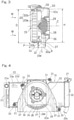
- Figs. 2 to 8 illustrate an assembled condition in which a cooling fan 28 and a fan covering 30 are assembled in the radiator 15.
- Figs. 2 and 3 illustrate a front elevational view and a longitudinal sectional view, respectively, of the radiator 15.
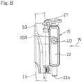
- the radiator 15 represents a rectangular shape of a horizontal format (elongated in a vehicle widthwise direction) when viewed from a front side, and includes a core 20 for draining the cooling medium through a plurality of fins in a horizontal direction.
- An introducing tank 21 for the cooling medium is provided at a right end (left side of a vehicle body) of the core 20 and a deriving tank 22 for the cooling medium is provided at a left end (right side of the vehicle body) of the core 20.
- the radiator 15 employed in the practice of the preferred embodiment of the present invention is a cross flow type.
- radiator that can be employed in the practice of the present invention is not necessarily limited to that type and may be of a vertical type in which the cooling medium is drained by the core 20 in an up and down direction or vertical direction.
- left side and rear side or similar notations, that are hereinabove and hereinafter used are to be understood as meaning relative terms descriptive of positions and/or directions as viewed from a vehicle rider occupying the seat.
- the introducing tank 21 is operable to introduce the cooling medium of a high temperature, that is discharged from the cylinder head 19 of the combustion engine E shown in Fig. 1 , and then guide it towards the core 20 shown in Fig. 2 .
- the introducing tank 21 has an upper end portion provided with a cylindrical cooling medium inlet 21a, and an introducing hose 24 for introducing the high temperature cooling medium from the cylinder head 19 (shown in Fig. 1 ) is fluid connected with this cooling medium inlet 21.
- the deriving tank 22 of the radiator 15 is operable to guide the cooling medium, which is lowered in temperature as a result of passage through the core 20, towards an engine E side.
- the deriving tank 22 has a lower end portion provided with a cylindrical cooling medium outlet 22a, and a deriving hose 25 is fluid connected with this cooling medium outlet 22a.
- the deriving tank 22 also has an upper end portion provided with a replenishing port 22b through which the cooling medium is replenished, and this replenishing port 22b is closed by a cap 27 during a normal time.
- the cooling fan 28 for ventilating the core 20 and an electric drive motor 29 for driving the cooling fan 28 are disposed on a back side (rear side) of the core 20 of the radiator 15, the cooling fan 28 for ventilating the core 20 and an electric drive motor 29 for driving the cooling fan 28 are disposed.
- the cooling fan 28 in the present embodiment includes a rotary blade assembly 36, drivingly connected with the electric drive motor 29, and a fan housing 37 for enclosing an outer periphery of the rotary blade assembly 36, but the fan housing 37 may be dispensed with.
- Areas above, on opposite lateral sides and on a downstream side (rear side) of both of the cooling fan 28 and the electric drive motor 29 are enclosed by the fan covering 30.
- the fan covering 30 has a downwardly oriented opening 30a defined therein.
- a partition wall 32 partitioning between a lower portion of the core 20 and a lower portion of the cooling fan 28 is provided radially outwardly of a front portion of the cooling fan 28.
- the partition wall 32 is operable to suppress a backflow of a discharge air DW through the opening 30a from flowing into the core 20.
- the axial position of a front surface of the partition wall 32 is in flush with a front surface of the rotary vane assembly 36 of the cooling fan 28.
- the core 20 is supported by a frame assembly 20b, which is rectangular in shape when viewed from front and which encloses the periphery of a plurality of fins.
- the partition wall 32 protrudes downwardly from an undersurface of the frame assembly 20b.
- the fan covering 30 has a plurality of mounting pieces 31 provided in the outer periphery thereof and is fitted to the frame assembly 20b of the core 20 with the plurality of the mounting pieces 31 secured thereto by means of screws.
- the fan covering 30 and both of the partition wall 32 and the mounting pieces 31 are of one piece construction formed of, for example, a resinous material with the use of any known molding technique.
- the fan covering 30, when viewed in a direction along a shaft axis C of the cooling fan 28, is of a generally inverted U-shape having a reduced width in an upper portion thereof and a large width in a lower portion thereof.
- the introducing tank 21 on a left side of the radiator 15 is fitted to the second frame piece 1b on a left side of the main frame 1 through a plate-shaped left side mounting piece 35L.
- the deriving tank 22 on a right side of the radiator 15 is fitted to the second frame piece 1b on a right side through a plate-shaped right side mounting piece 35R.
- the cooling fan 28 is covered by the fan housing 37.
- the electric drive motor 29 is disposed rearwardly of this cooling fan 28 and both of the cooling fan 28 and the electric drive motor 29 are covered by the fan covering 30.
- the left side mounting piece 35L is welded to the introducing tank 21 of the radiator 15, and this left side mounting piece 35L is removably fitted to the second frame piece 1b on the left side by means of two, upper and lower screw members 39 and 39.
- the right side mounting piece 36R is welded to the second frame piece 1b on the right side, and this right side mounting piece 35R is removably fitted to the deriving tank 22 on the right side of the radiator 15 by means of a single screw member 40.
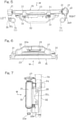
- the partition wall 32 includes a region confronting the outer periphery of the cooling fan 28, that is, a fan adjacent region proximate to the outer periphery of the fan housing 37, formed with a guide portion 34.
- This guide portion 34 is so inclined on a downstream side (rear side) towards a radial inner side of the cooling fan 28 so that air can be guided towards the outer periphery of the fan housing 37 of the cooling fan 28.
- This guide portion 34 is provided to confront the outer periphery of a lower half of the cooling fan 28 as shown in Fig. 4 . As shown in Fig.
- the angle of inclination ⁇ of the guide portion 34 relative to a surface perpendicular to a shaft axis C, that is, a cooling fan front surface is so chosen as to be within the range of 30 to 60° and, preferably, within the range of 40 to 50°.
- the length P of protrusion of the partition wall 32 in a direction downwardly from the core 20 is so chosen as to be 0.1 to 0.3 times the vertical length H of the core 20 and, preferably, 0.15 to 0.25 times the vertical length H. If the protrusion length P is not greater than 0.1 times the vertical length H, no sufficient effect of preventing the discharge air DW from flowing backwardly can be obtained. The backward flow preventive effect will be sufficient if the protrusion length P is 0.3 times the vertical length H.
- the radiator 15 is so configured that areas above and on opposite sides and on a downstream side (rear side) of the cooling fan 28 for ventilating the core 20 are covered by the downwardly opened fan covering 30. Therefore, the discharge air DW flowing through the core 20 of the radiator 15 and the cooling fan 28 is assuredly discharged in a direction downwardly from the downwardly oriented opening 30a of the fan covering 30. Accordingly, the rider will not be exposed to the discharge air DW.
- the discharge air DW having passed through the cooling fan 28 is discharged from the opening 30a of the fan covering 30, if a portion of the discharge air DW will be likely to flow backwards, as shown by the arrow shown by the double dotted line, in a direction forwardly of the vehicle body, the backward flow of the discharge air DW can be blocked by the partition wall 32. Therefore, the discharge air DW can be prevented from being again sucked from front into the core 20. Accordingly, the heat radiating efficiency of the radiator 15 will not be lowered as a result of entanglement of the discharge air DW of high temperature, thus allowing the radiator 15 to exhibit its original performance.
- the outer diameter D of the cooling fan 28 is made large enough to allow the diameter D to become substantially equal to the vertical length H of the core 20. Therefore, the heat radiating efficiency can be increased by guiding air towards a major portion of the core 20 even under a condition in which the incoming wind W cannot be utilized sufficiently such as during, for example, a low speed running or parking. Also, the length P of protrusion of the fan covering 30 downwardly from the core 20 is made small enough to become 0.1 to 0.3 times the vertical length H of the core 20. Accordingly, the fan covering 30 will not become large in size unnecessarily and, therefore, the increase in size of the radiator 15 in its entirety including the fan covering 30 can be suppressed.
- the guide portion 34 is formed in the fan adjacent region of the partition wall 32, which faces the outer periphery of the cooling fan 28, and the air can be guided toward the outer periphery of the fan housing 37 of the cooling fan 28 along the guide portion 34. Accordingly, even when the discharge air DW entangles over the partition wall 32 and downwardly of the core 20, the discharge air DW can be guided towards the outer periphery of the fan housing 37 together with air. As a result, the discharge air DW can be quickly discharged from the downwardly oriented opening 30a of the fan covering 30 without passing again in the cooling fan 28.
- the guide portion 34 is provided so as to confront the lower half portion of the cooling fan 28, the back flow of the discharge air DW, which is to be discharged downwardly from the cooling fan 28, in a direction forwardly of the core 20 can be suppressed while the size of the fan covering 30 is made as small as possible.
- the fan covering 30 is fitted to the core 20 through the mounting piece 31, and the fan covering 30, the partition wall 32 and the mounting piece 31 form the one piece structure. Accordingly, the handlability is increased with the number of component parts reduced and, also, the fitting of the fan covering 30 to the core 20 can be conveniently performed.
- the rear wall 3c for enclosing the cooling fan 28 from the downstream side (rear side) as shown in Fig. 3 lies perpendicular to the shaft axis C of the cooling fan 28.
- the rear wall 30c is inclined rearwardly from top to down, that is, a so-called flaring fan outlet space is formed, the axial dimension of an upper portion of the fan outlet space, that is, the depth of an upper portion of the fan covering 30 is increased. Accordingly, the discharge air DW from the downwardly oriented opening 30a of the fan covering 30 can be smoothly discharged.
- the upper portion of the core 20 is sufficiently ventilated and the heat radiating efficiency of the radiator 15 increases accordingly.
- the saddle-riding vehicle referred to hereinabove has been shown and described as the motorcycle, the present invention can be equally applied even when the saddle-riding vehicle is a three or four-wheeled vehicle such as an irregular ground travelling vehicle.
- an electric drive motor may be used for the drive source.
Landscapes
- Engineering & Computer Science (AREA)
- Mechanical Engineering (AREA)
- Chemical & Material Sciences (AREA)
- Combustion & Propulsion (AREA)
- Transportation (AREA)
- Cooling, Air Intake And Gas Exhaust, And Fuel Tank Arrangements In Propulsion Units (AREA)
Applications Claiming Priority (2)
| Application Number | Priority Date | Filing Date | Title |
|---|---|---|---|
| JP2014083378A JP6243282B2 (ja) | 2014-04-15 | 2014-04-15 | 鞍乗型車両のラジエータ |
| PCT/JP2015/053054 WO2015159571A1 (ja) | 2014-04-15 | 2015-02-04 | 鞍乗型車両のラジエータ |
Publications (3)
| Publication Number | Publication Date |
|---|---|
| EP3133007A1 EP3133007A1 (en) | 2017-02-22 |
| EP3133007A4 EP3133007A4 (en) | 2018-01-03 |
| EP3133007B1 true EP3133007B1 (en) | 2022-01-26 |
Family
ID=54323789
Family Applications (1)
| Application Number | Title | Priority Date | Filing Date |
|---|---|---|---|
| EP15780445.1A Active EP3133007B1 (en) | 2014-04-15 | 2015-02-04 | Radiator for saddled vehicle |
Country Status (4)
| Country | Link |
|---|---|
| US (1) | US10124662B2 (enExample) |
| EP (1) | EP3133007B1 (enExample) |
| JP (1) | JP6243282B2 (enExample) |
| WO (1) | WO2015159571A1 (enExample) |
Families Citing this family (16)
| Publication number | Priority date | Publication date | Assignee | Title |
|---|---|---|---|---|
| MX2017014403A (es) | 2015-05-15 | 2018-04-11 | Polaris Inc | Vehiculo utilitario. |
| JP6437981B2 (ja) * | 2016-10-20 | 2018-12-12 | 本田技研工業株式会社 | 鞍乗型車両 |
| US11173808B2 (en) | 2016-12-22 | 2021-11-16 | Polaris Industies Inc. | Vehicle |
| IT201600130142A1 (it) * | 2016-12-22 | 2018-06-22 | Piaggio & C Spa | Sistema di raffreddamento del motore di un motoveicolo |
| US10589621B1 (en) | 2017-05-24 | 2020-03-17 | Indian Motorcycle International, LLC | Two-wheeled vehicle |
| US10655536B1 (en) | 2017-05-24 | 2020-05-19 | Indian Motorcycle International, LLC | Engine |
| JP6689798B2 (ja) * | 2017-08-30 | 2020-04-28 | 本田技研工業株式会社 | 鞍乗り型車両 |
| CA3299413A1 (en) | 2019-04-30 | 2026-03-02 | Polaris Industries Inc. | Vehicle with removable final drive |
| DE102019115786B4 (de) * | 2019-06-11 | 2021-03-04 | Bayerische Motoren Werke Aktiengesellschaft | Elektromotorrad |
| JP2021160372A (ja) * | 2020-03-30 | 2021-10-11 | 本田技研工業株式会社 | ラジエータ |
| US11674432B2 (en) * | 2020-04-23 | 2023-06-13 | Clark Equipment Company | Identification and reduction of backflow suction in cooling systems |
| US11691674B2 (en) | 2020-05-15 | 2023-07-04 | Polaris Industries Inc. | Off-road vehicle |
| US12187127B2 (en) | 2020-05-15 | 2025-01-07 | Polaris Industries Inc. | Off-road vehicle |
| CN112208690B (zh) * | 2020-10-13 | 2022-01-25 | 唐山金亨通车料有限公司 | 一种可快速降温自行车坐垫 |
| JP7773853B2 (ja) * | 2020-11-12 | 2025-11-20 | カワサキモータース株式会社 | 鞍乗型車両 |
| MX2023006716A (es) | 2022-06-13 | 2023-12-14 | Polaris Inc | Tren de potencia para vehiculo utilitario. |
Family Cites Families (17)
| Publication number | Priority date | Publication date | Assignee | Title |
|---|---|---|---|---|
| JPS59114178A (ja) * | 1982-12-17 | 1984-07-02 | ヤマハ発動機株式会社 | スク−タ型車輌 |
| JPH01262278A (ja) * | 1988-04-11 | 1989-10-19 | Yamaha Motor Co Ltd | 自動二,三輪車のエンジン冷却装置 |
| JP2002019662A (ja) * | 2000-07-05 | 2002-01-23 | Yamaha Motor Co Ltd | スクータ型車両用フロント側カバー構造 |
| DE102004018036A1 (de) * | 2004-04-08 | 2005-11-10 | Behr Gmbh & Co. Kg | Kühlsystem |
| JP2008013149A (ja) | 2006-07-10 | 2008-01-24 | Honda Motor Co Ltd | 車両の導風板 |
| CN101164825A (zh) * | 2006-10-16 | 2008-04-23 | 光阳工业股份有限公司 | 热气导引装置 |
| JP4986685B2 (ja) * | 2007-03-30 | 2012-07-25 | 本田技研工業株式会社 | 自動2輪車用エンジンの冷却装置 |
| JP4160105B2 (ja) * | 2007-11-12 | 2008-10-01 | 本田技研工業株式会社 | スクータ型車両用燃料タンクの遮熱構造 |
| US8539929B2 (en) * | 2009-11-18 | 2013-09-24 | Harley-Davidson Motor Company | Cylinder head cooling system |
| JP2011173484A (ja) * | 2010-02-24 | 2011-09-08 | Honda Motor Co Ltd | 車両用冷却装置 |
| JP5829907B2 (ja) * | 2011-12-28 | 2015-12-09 | 川崎重工業株式会社 | 鞍乗型車両 |
| JP5916456B2 (ja) | 2012-03-22 | 2016-05-11 | 本田技研工業株式会社 | 鞍乗り型車両のラジエータ用排風構造 |
| JP5963196B2 (ja) * | 2012-07-31 | 2016-08-03 | 本田技研工業株式会社 | 鞍乗り型車両におけるラジエータの通風構造 |
| WO2015036985A1 (en) * | 2013-09-13 | 2015-03-19 | Bombardier Recreational Products Inc. | Radiator assembly for a vehicle |
| JP2015217829A (ja) * | 2014-05-19 | 2015-12-07 | 本田技研工業株式会社 | 車両の冷却構造 |
| JP6280483B2 (ja) * | 2014-09-30 | 2018-02-14 | 本田技研工業株式会社 | 鞍乗り型車両の冷却構造 |
| JP6122820B2 (ja) * | 2014-09-30 | 2017-04-26 | 本田技研工業株式会社 | 鞍乗り型車両 |
-
2014
- 2014-04-15 JP JP2014083378A patent/JP6243282B2/ja active Active
-
2015
- 2015-02-04 EP EP15780445.1A patent/EP3133007B1/en active Active
- 2015-02-04 WO PCT/JP2015/053054 patent/WO2015159571A1/ja not_active Ceased
-
2016
- 2016-10-05 US US15/286,343 patent/US10124662B2/en active Active
Also Published As
| Publication number | Publication date |
|---|---|
| JP6243282B2 (ja) | 2017-12-06 |
| WO2015159571A1 (ja) | 2015-10-22 |
| JP2015202791A (ja) | 2015-11-16 |
| US20170021719A1 (en) | 2017-01-26 |
| US10124662B2 (en) | 2018-11-13 |
| EP3133007A1 (en) | 2017-02-22 |
| EP3133007A4 (en) | 2018-01-03 |
Similar Documents
| Publication | Publication Date | Title |
|---|---|---|
| EP3133007B1 (en) | Radiator for saddled vehicle | |
| US10293655B2 (en) | Ventilation structure of radiator in straddle type vehicle | |
| JP4586438B2 (ja) | 不整地走行車両の前部構造 | |
| CN104822583B (zh) | 用于车辆的空气通风系统 | |
| US8783399B2 (en) | Saddle-riding type vehicle including multi-part shroud | |
| JP6163518B2 (ja) | 冷却装置 | |
| JP6147540B2 (ja) | 鞍乗り型車両 | |
| JP6845766B2 (ja) | 鞍乗型車両及びラジエータ導風装置 | |
| JP2011073537A (ja) | 冷却装置のシュラウド構造 | |
| JP6689798B2 (ja) | 鞍乗り型車両 | |
| EP3348462B1 (en) | Straddled vehicle | |
| FR2532892A1 (fr) | Motocycle avec moteur a refroidissement par eau | |
| EP2055520B1 (en) | Radiator cover and straddle-type vehicle having the same | |
| JP2008201230A (ja) | 鞍乗型車両 | |
| EP2159093A1 (en) | Motorcycle | |
| JPH06171568A (ja) | 自動2輪車のエンジン冷却装置 | |
| JP6795681B2 (ja) | 鞍乗り型車両 | |
| WO2013111155A1 (en) | Scooter type vehicle | |
| EP3726020B1 (en) | A cooling system | |
| JP6175123B2 (ja) | 鞍乗り型車両のラジエータ構造 |
Legal Events
| Date | Code | Title | Description |
|---|---|---|---|
| STAA | Information on the status of an ep patent application or granted ep patent |
Free format text: STATUS: THE INTERNATIONAL PUBLICATION HAS BEEN MADE |
|
| PUAI | Public reference made under article 153(3) epc to a published international application that has entered the european phase |
Free format text: ORIGINAL CODE: 0009012 |
|
| STAA | Information on the status of an ep patent application or granted ep patent |
Free format text: STATUS: REQUEST FOR EXAMINATION WAS MADE |
|
| 17P | Request for examination filed |
Effective date: 20161014 |
|
| AK | Designated contracting states |
Kind code of ref document: A1 Designated state(s): AL AT BE BG CH CY CZ DE DK EE ES FI FR GB GR HR HU IE IS IT LI LT LU LV MC MK MT NL NO PL PT RO RS SE SI SK SM TR |
|
| AX | Request for extension of the european patent |
Extension state: BA ME |
|
| DAX | Request for extension of the european patent (deleted) | ||
| A4 | Supplementary search report drawn up and despatched |
Effective date: 20171205 |
|
| RIC1 | Information provided on ipc code assigned before grant |
Ipc: B62J 99/00 20090101AFI20171129BHEP Ipc: B62J 23/00 20060101ALI20171129BHEP |
|
| STAA | Information on the status of an ep patent application or granted ep patent |
Free format text: STATUS: EXAMINATION IS IN PROGRESS |
|
| 17Q | First examination report despatched |
Effective date: 20180914 |
|
| REG | Reference to a national code |
Ref country code: DE Ref legal event code: R079 Ref document number: 602015076668 Country of ref document: DE Free format text: PREVIOUS MAIN CLASS: B62J0099000000 Ipc: B62J0017100000 |
|
| RIC1 | Information provided on ipc code assigned before grant |
Ipc: B62J 17/10 20200101AFI20201014BHEP Ipc: B62J 41/00 20200101ALI20201014BHEP |
|
| GRAP | Despatch of communication of intention to grant a patent |
Free format text: ORIGINAL CODE: EPIDOSNIGR1 |
|
| STAA | Information on the status of an ep patent application or granted ep patent |
Free format text: STATUS: GRANT OF PATENT IS INTENDED |
|
| INTG | Intention to grant announced |
Effective date: 20201123 |
|
| GRAJ | Information related to disapproval of communication of intention to grant by the applicant or resumption of examination proceedings by the epo deleted |
Free format text: ORIGINAL CODE: EPIDOSDIGR1 |
|
| STAA | Information on the status of an ep patent application or granted ep patent |
Free format text: STATUS: EXAMINATION IS IN PROGRESS |
|
| INTC | Intention to grant announced (deleted) | ||
| GRAP | Despatch of communication of intention to grant a patent |
Free format text: ORIGINAL CODE: EPIDOSNIGR1 |
|
| STAA | Information on the status of an ep patent application or granted ep patent |
Free format text: STATUS: GRANT OF PATENT IS INTENDED |
|
| INTG | Intention to grant announced |
Effective date: 20211117 |
|
| GRAS | Grant fee paid |
Free format text: ORIGINAL CODE: EPIDOSNIGR3 |
|
| GRAA | (expected) grant |
Free format text: ORIGINAL CODE: 0009210 |
|
| STAA | Information on the status of an ep patent application or granted ep patent |
Free format text: STATUS: THE PATENT HAS BEEN GRANTED |
|
| AK | Designated contracting states |
Kind code of ref document: B1 Designated state(s): AL AT BE BG CH CY CZ DE DK EE ES FI FR GB GR HR HU IE IS IT LI LT LU LV MC MK MT NL NO PL PT RO RS SE SI SK SM TR |
|
| REG | Reference to a national code |
Ref country code: GB Ref legal event code: FG4D |
|
| REG | Reference to a national code |
Ref country code: CH Ref legal event code: EP |
|
| REG | Reference to a national code |
Ref country code: AT Ref legal event code: REF Ref document number: 1465076 Country of ref document: AT Kind code of ref document: T Effective date: 20220215 |
|
| REG | Reference to a national code |
Ref country code: IE Ref legal event code: FG4D |
|
| REG | Reference to a national code |
Ref country code: DE Ref legal event code: R096 Ref document number: 602015076668 Country of ref document: DE |
|
| REG | Reference to a national code |
Ref country code: DE Ref legal event code: R081 Ref document number: 602015076668 Country of ref document: DE Owner name: KAWASAKI MOTORS, LTD., AKASHI-SHI, JP Free format text: FORMER OWNER: KAWASAKI JUKOGYO KABUSHIKI KAISHA, KOBE-SHI, HYOGO, JP |
|
| REG | Reference to a national code |
Ref country code: LT Ref legal event code: MG9D |
|
| REG | Reference to a national code |
Ref country code: NL Ref legal event code: MP Effective date: 20220126 |
|
| REG | Reference to a national code |
Ref country code: AT Ref legal event code: MK05 Ref document number: 1465076 Country of ref document: AT Kind code of ref document: T Effective date: 20220126 |
|
| PG25 | Lapsed in a contracting state [announced via postgrant information from national office to epo] |
Ref country code: NL Free format text: LAPSE BECAUSE OF FAILURE TO SUBMIT A TRANSLATION OF THE DESCRIPTION OR TO PAY THE FEE WITHIN THE PRESCRIBED TIME-LIMIT Effective date: 20220126 |
|
| PG25 | Lapsed in a contracting state [announced via postgrant information from national office to epo] |
Ref country code: SE Free format text: LAPSE BECAUSE OF FAILURE TO SUBMIT A TRANSLATION OF THE DESCRIPTION OR TO PAY THE FEE WITHIN THE PRESCRIBED TIME-LIMIT Effective date: 20220126 Ref country code: RS Free format text: LAPSE BECAUSE OF FAILURE TO SUBMIT A TRANSLATION OF THE DESCRIPTION OR TO PAY THE FEE WITHIN THE PRESCRIBED TIME-LIMIT Effective date: 20220126 Ref country code: PT Free format text: LAPSE BECAUSE OF FAILURE TO SUBMIT A TRANSLATION OF THE DESCRIPTION OR TO PAY THE FEE WITHIN THE PRESCRIBED TIME-LIMIT Effective date: 20220526 Ref country code: NO Free format text: LAPSE BECAUSE OF FAILURE TO SUBMIT A TRANSLATION OF THE DESCRIPTION OR TO PAY THE FEE WITHIN THE PRESCRIBED TIME-LIMIT Effective date: 20220426 Ref country code: LT Free format text: LAPSE BECAUSE OF FAILURE TO SUBMIT A TRANSLATION OF THE DESCRIPTION OR TO PAY THE FEE WITHIN THE PRESCRIBED TIME-LIMIT Effective date: 20220126 Ref country code: HR Free format text: LAPSE BECAUSE OF FAILURE TO SUBMIT A TRANSLATION OF THE DESCRIPTION OR TO PAY THE FEE WITHIN THE PRESCRIBED TIME-LIMIT Effective date: 20220126 Ref country code: ES Free format text: LAPSE BECAUSE OF FAILURE TO SUBMIT A TRANSLATION OF THE DESCRIPTION OR TO PAY THE FEE WITHIN THE PRESCRIBED TIME-LIMIT Effective date: 20220126 Ref country code: BG Free format text: LAPSE BECAUSE OF FAILURE TO SUBMIT A TRANSLATION OF THE DESCRIPTION OR TO PAY THE FEE WITHIN THE PRESCRIBED TIME-LIMIT Effective date: 20220426 |
|
| PG25 | Lapsed in a contracting state [announced via postgrant information from national office to epo] |
Ref country code: PL Free format text: LAPSE BECAUSE OF FAILURE TO SUBMIT A TRANSLATION OF THE DESCRIPTION OR TO PAY THE FEE WITHIN THE PRESCRIBED TIME-LIMIT Effective date: 20220126 Ref country code: LV Free format text: LAPSE BECAUSE OF FAILURE TO SUBMIT A TRANSLATION OF THE DESCRIPTION OR TO PAY THE FEE WITHIN THE PRESCRIBED TIME-LIMIT Effective date: 20220126 Ref country code: GR Free format text: LAPSE BECAUSE OF FAILURE TO SUBMIT A TRANSLATION OF THE DESCRIPTION OR TO PAY THE FEE WITHIN THE PRESCRIBED TIME-LIMIT Effective date: 20220427 Ref country code: FI Free format text: LAPSE BECAUSE OF FAILURE TO SUBMIT A TRANSLATION OF THE DESCRIPTION OR TO PAY THE FEE WITHIN THE PRESCRIBED TIME-LIMIT Effective date: 20220126 Ref country code: AT Free format text: LAPSE BECAUSE OF FAILURE TO SUBMIT A TRANSLATION OF THE DESCRIPTION OR TO PAY THE FEE WITHIN THE PRESCRIBED TIME-LIMIT Effective date: 20220126 |
|
| PG25 | Lapsed in a contracting state [announced via postgrant information from national office to epo] |
Ref country code: IS Free format text: LAPSE BECAUSE OF FAILURE TO SUBMIT A TRANSLATION OF THE DESCRIPTION OR TO PAY THE FEE WITHIN THE PRESCRIBED TIME-LIMIT Effective date: 20220526 |
|
| REG | Reference to a national code |
Ref country code: CH Ref legal event code: PL |
|
| REG | Reference to a national code |
Ref country code: BE Ref legal event code: MM Effective date: 20220228 |
|
| REG | Reference to a national code |
Ref country code: DE Ref legal event code: R097 Ref document number: 602015076668 Country of ref document: DE |
|
| PG25 | Lapsed in a contracting state [announced via postgrant information from national office to epo] |
Ref country code: SM Free format text: LAPSE BECAUSE OF FAILURE TO SUBMIT A TRANSLATION OF THE DESCRIPTION OR TO PAY THE FEE WITHIN THE PRESCRIBED TIME-LIMIT Effective date: 20220126 Ref country code: SK Free format text: LAPSE BECAUSE OF FAILURE TO SUBMIT A TRANSLATION OF THE DESCRIPTION OR TO PAY THE FEE WITHIN THE PRESCRIBED TIME-LIMIT Effective date: 20220126 Ref country code: RO Free format text: LAPSE BECAUSE OF FAILURE TO SUBMIT A TRANSLATION OF THE DESCRIPTION OR TO PAY THE FEE WITHIN THE PRESCRIBED TIME-LIMIT Effective date: 20220126 Ref country code: MC Free format text: LAPSE BECAUSE OF FAILURE TO SUBMIT A TRANSLATION OF THE DESCRIPTION OR TO PAY THE FEE WITHIN THE PRESCRIBED TIME-LIMIT Effective date: 20220126 Ref country code: LU Free format text: LAPSE BECAUSE OF NON-PAYMENT OF DUE FEES Effective date: 20220204 Ref country code: EE Free format text: LAPSE BECAUSE OF FAILURE TO SUBMIT A TRANSLATION OF THE DESCRIPTION OR TO PAY THE FEE WITHIN THE PRESCRIBED TIME-LIMIT Effective date: 20220126 Ref country code: DK Free format text: LAPSE BECAUSE OF FAILURE TO SUBMIT A TRANSLATION OF THE DESCRIPTION OR TO PAY THE FEE WITHIN THE PRESCRIBED TIME-LIMIT Effective date: 20220126 Ref country code: CZ Free format text: LAPSE BECAUSE OF FAILURE TO SUBMIT A TRANSLATION OF THE DESCRIPTION OR TO PAY THE FEE WITHIN THE PRESCRIBED TIME-LIMIT Effective date: 20220126 |
|
| PG25 | Lapsed in a contracting state [announced via postgrant information from national office to epo] |
Ref country code: AL Free format text: LAPSE BECAUSE OF FAILURE TO SUBMIT A TRANSLATION OF THE DESCRIPTION OR TO PAY THE FEE WITHIN THE PRESCRIBED TIME-LIMIT Effective date: 20220126 |
|
| PLBE | No opposition filed within time limit |
Free format text: ORIGINAL CODE: 0009261 |
|
| STAA | Information on the status of an ep patent application or granted ep patent |
Free format text: STATUS: NO OPPOSITION FILED WITHIN TIME LIMIT |
|
| GBPC | Gb: european patent ceased through non-payment of renewal fee |
Effective date: 20220426 |
|
| 26N | No opposition filed |
Effective date: 20221027 |
|
| PG25 | Lapsed in a contracting state [announced via postgrant information from national office to epo] |
Ref country code: LI Free format text: LAPSE BECAUSE OF NON-PAYMENT OF DUE FEES Effective date: 20220228 Ref country code: IE Free format text: LAPSE BECAUSE OF NON-PAYMENT OF DUE FEES Effective date: 20220204 Ref country code: GB Free format text: LAPSE BECAUSE OF NON-PAYMENT OF DUE FEES Effective date: 20220426 Ref country code: FR Free format text: LAPSE BECAUSE OF NON-PAYMENT OF DUE FEES Effective date: 20220326 Ref country code: CH Free format text: LAPSE BECAUSE OF NON-PAYMENT OF DUE FEES Effective date: 20220228 |
|
| PG25 | Lapsed in a contracting state [announced via postgrant information from national office to epo] |
Ref country code: SI Free format text: LAPSE BECAUSE OF FAILURE TO SUBMIT A TRANSLATION OF THE DESCRIPTION OR TO PAY THE FEE WITHIN THE PRESCRIBED TIME-LIMIT Effective date: 20220126 Ref country code: BE Free format text: LAPSE BECAUSE OF NON-PAYMENT OF DUE FEES Effective date: 20220228 |
|
| PG25 | Lapsed in a contracting state [announced via postgrant information from national office to epo] |
Ref country code: IT Free format text: LAPSE BECAUSE OF FAILURE TO SUBMIT A TRANSLATION OF THE DESCRIPTION OR TO PAY THE FEE WITHIN THE PRESCRIBED TIME-LIMIT Effective date: 20220126 |
|
| PG25 | Lapsed in a contracting state [announced via postgrant information from national office to epo] |
Ref country code: HU Free format text: LAPSE BECAUSE OF FAILURE TO SUBMIT A TRANSLATION OF THE DESCRIPTION OR TO PAY THE FEE WITHIN THE PRESCRIBED TIME-LIMIT; INVALID AB INITIO Effective date: 20150204 |
|
| PG25 | Lapsed in a contracting state [announced via postgrant information from national office to epo] |
Ref country code: MK Free format text: LAPSE BECAUSE OF FAILURE TO SUBMIT A TRANSLATION OF THE DESCRIPTION OR TO PAY THE FEE WITHIN THE PRESCRIBED TIME-LIMIT Effective date: 20220126 Ref country code: CY Free format text: LAPSE BECAUSE OF FAILURE TO SUBMIT A TRANSLATION OF THE DESCRIPTION OR TO PAY THE FEE WITHIN THE PRESCRIBED TIME-LIMIT Effective date: 20220126 |
|
| PG25 | Lapsed in a contracting state [announced via postgrant information from national office to epo] |
Ref country code: MT Free format text: LAPSE BECAUSE OF FAILURE TO SUBMIT A TRANSLATION OF THE DESCRIPTION OR TO PAY THE FEE WITHIN THE PRESCRIBED TIME-LIMIT Effective date: 20220126 |
|
| PG25 | Lapsed in a contracting state [announced via postgrant information from national office to epo] |
Ref country code: TR Free format text: LAPSE BECAUSE OF FAILURE TO SUBMIT A TRANSLATION OF THE DESCRIPTION OR TO PAY THE FEE WITHIN THE PRESCRIBED TIME-LIMIT Effective date: 20220126 |
|
| PGFP | Annual fee paid to national office [announced via postgrant information from national office to epo] |
Ref country code: DE Payment date: 20251230 Year of fee payment: 12 |