WO2015159571A1 - Radiator for saddled vehicle - Google Patents
Radiator for saddled vehicle Download PDFInfo
- Publication number
- WO2015159571A1 WO2015159571A1 PCT/JP2015/053054 JP2015053054W WO2015159571A1 WO 2015159571 A1 WO2015159571 A1 WO 2015159571A1 JP 2015053054 W JP2015053054 W JP 2015053054W WO 2015159571 A1 WO2015159571 A1 WO 2015159571A1
- Authority
- WO
- WIPO (PCT)
- Prior art keywords
- radiator
- fan
- core
- cooling fan
- cooling
- Prior art date
Links
Images

Classifications
-
- B—PERFORMING OPERATIONS; TRANSPORTING
- B62—LAND VEHICLES FOR TRAVELLING OTHERWISE THAN ON RAILS
- B62J—CYCLE SADDLES OR SEATS; AUXILIARY DEVICES OR ACCESSORIES SPECIALLY ADAPTED TO CYCLES AND NOT OTHERWISE PROVIDED FOR, e.g. ARTICLE CARRIERS OR CYCLE PROTECTORS
- B62J41/00—Arrangements of radiators, coolant hoses or pipes on cycles
-
- B—PERFORMING OPERATIONS; TRANSPORTING
- B60—VEHICLES IN GENERAL
- B60K—ARRANGEMENT OR MOUNTING OF PROPULSION UNITS OR OF TRANSMISSIONS IN VEHICLES; ARRANGEMENT OR MOUNTING OF PLURAL DIVERSE PRIME-MOVERS IN VEHICLES; AUXILIARY DRIVES FOR VEHICLES; INSTRUMENTATION OR DASHBOARDS FOR VEHICLES; ARRANGEMENTS IN CONNECTION WITH COOLING, AIR INTAKE, GAS EXHAUST OR FUEL SUPPLY OF PROPULSION UNITS IN VEHICLES
- B60K11/00—Arrangement in connection with cooling of propulsion units
- B60K11/02—Arrangement in connection with cooling of propulsion units with liquid cooling
- B60K11/04—Arrangement or mounting of radiators, radiator shutters, or radiator blinds
-
- B—PERFORMING OPERATIONS; TRANSPORTING
- B62—LAND VEHICLES FOR TRAVELLING OTHERWISE THAN ON RAILS
- B62J—CYCLE SADDLES OR SEATS; AUXILIARY DEVICES OR ACCESSORIES SPECIALLY ADAPTED TO CYCLES AND NOT OTHERWISE PROVIDED FOR, e.g. ARTICLE CARRIERS OR CYCLE PROTECTORS
- B62J17/00—Weather guards for riders; Fairings or stream-lining parts not otherwise provided for
- B62J17/10—Ventilation or air guiding devices forming part of fairings
-
- B—PERFORMING OPERATIONS; TRANSPORTING
- B62—LAND VEHICLES FOR TRAVELLING OTHERWISE THAN ON RAILS
- B62J—CYCLE SADDLES OR SEATS; AUXILIARY DEVICES OR ACCESSORIES SPECIALLY ADAPTED TO CYCLES AND NOT OTHERWISE PROVIDED FOR, e.g. ARTICLE CARRIERS OR CYCLE PROTECTORS
- B62J23/00—Other protectors specially adapted for cycles
Definitions
- the present invention relates to a radiator that is mounted on a straddle-type vehicle such as a motorcycle and radiates heat from an engine coolant.
- Patent Document 1 As a radiator mounted on a saddle riding type vehicle such as a motorcycle, an electric fan disposed close to the radiator heat dissipation core from the downstream side of the traveling wind and a shroud covering the electric fan are provided. There exists a thing of a structure (for example, patent document 1).
- the shroud of Patent Document 1 covers the electric fan from the downstream side of the traveling wind and also covers the electric fan from the upper side to the both sides and opens downward.
- An object of the present invention is to provide a radiator for a saddle-ride type vehicle in which heat dissipation efficiency does not decrease by preventing the exhaust air that has passed through the fan of the radiator and discharged to the lower side of the fan from flowing backward to the front of the core of the radiator. is there.
- a radiator of a saddle riding type vehicle is a radiator that dissipates heat from a cooling medium of a prime mover mounted on the saddle riding type vehicle, and a core through which the cooling medium flows and a downstream thereof
- a cooling fan disposed on the side and ventilating the core; a fan cover that covers the upper side, both sides, and the downstream side of the cooling fan; and opens downward; and a space between the lower part of the core and the lower part of the cooling fan And a partition wall that suppresses the exhaust air from the opening from flowing back to the core.
- the partition wall protrudes downward from the core. According to this configuration, since the exhaust air is reliably prevented from flowing downwardly of the radiator, it is possible to more efficiently prevent a part of the exhaust air from flowing backward to the front of the radiator.
- the outer diameter D of the cooling fan is substantially the same as the vertical length H of the core, and the protruding length P of the fan cover downward from the core is the vertical length H of the core. Is preferably 0.1 to 0.3 times.
- the fan outer diameter D is increased so as to be substantially the same as the length H of the core. Therefore, even when the traveling wind cannot be used sufficiently, such as when driving at low speed or when stopping, The heat radiation efficiency can be improved by introducing air to the part. Further, since the protrusion length P is set to 0.1 to 0.3H, the size of the fan cover does not become larger than necessary.
- the size of the entire radiator including the fan cover is suppressed, and the fan cover can be smoothly smoothed while suppressing the speed of exhaust air from the cooling fan of the radiator from being reduced by friction loss with the fan cover inner surface. It can be discharged from the opening below.
- the exhaust air is downstream in the radially inner side of the cooling fan so as to guide the exhaust air to the outer periphery of the fan housing of the cooling fan in the fan proximity region of the partition wall facing the outer periphery of the cooling fan.
- the guide part which inclines to the side is formed.
- the inclination angle ⁇ of the guide portion with respect to the front surface of the cooling fan is, for example, 30 to 60 °. According to this configuration, the exhaust air can be guided to the outer periphery of the fan housing of the cooling fan along the guide portion, and the exhaust air guided to the outer periphery of the fan housing does not pass through the cooling fan again. It can be quickly discharged from the lower opening of the cover.
- the guide portion is provided to face an outer periphery of a lower half of the cooling fan. According to this configuration, it is possible to suppress the exhaust air discharged downward from the cooling fan from flowing backward to the front of the core while miniaturizing the fan cover as much as possible.
- the fan cover is attached to the core via an attachment piece, and the fan cover, the partition wall, and the attachment piece are integrally formed. According to this configuration, the handleability is improved by reducing the number of parts, and the fan cover can be easily attached to the core.
- a rear wall that covers the cooling fan from the downstream side is orthogonal to the axis of the cooling fan.
- the fan outlet space Since the dimension of the upper part in the axial direction, that is, the depth of the upper part of the fan cover increases, the upper part of the core is sufficiently ventilated to improve the heat radiation efficiency.
- the fan cover has a generally inverted U shape with a narrow upper portion and a wide lower portion as viewed from the axial center of the cooling fan. According to this configuration, the fan outlet space that extends in the width direction from the upper side to the lower side is formed, so that the downward air discharge becomes smooth.
- FIG. 1 is a side view showing a front half portion of a motorcycle including a radiator according to a preferred embodiment of the present invention. It is the front view which looked at the same radiator from the front side. It is a longitudinal cross-sectional view of the same radiator. It is the rear view which looked at the same radiator from the back side. It is a top view of the same radiator. It is a bottom view of the same radiator. It is the side view which looked at the same radiator from the left side of the body. It is the side view which looked at the same radiator from the right side of a vehicle body.
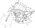
- FIG. 1 shows a front half of a motorcycle to which a radiator according to a preferred embodiment of the present invention is applied.
- the motorcycle of the present invention has a main frame 1 that forms the front half of the vehicle body frame FR and a rear frame 12 that forms the rear half.
- a front fork 2 is supported at the front end of the main frame 1, and a front wheel 4 is supported via an axle 5 on a bottom case 3 provided at the lower end of the front fork 2.
- the front fork 2 is rotatably supported by a head pipe 8 at the front end of the main frame 1 together with an upper bracket 6 and a lower bracket 7 that support the front fork 2, and a handle 10 is attached to the upper bracket 6.
- a swing arm bracket 11 is fixed to the lower portion of the rear end of the main frame 1, and a swing arm that supports a rear wheel (not shown) is pivotally supported by the swing arm bracket 11 so as to be swingable.
- An engine E which is a prime mover for driving the rear wheels, is supported at the lower center of the main frame 1.
- the main frame 1 has a pair of left and right first frame pieces 1a, 1a that extend in the front-rear direction and then bend and extend downward.
- the upper end of the main frame 1 is joined to the rear of the head pipe 8 at the front part of the first frame piece 1a.
- a pair of left and right fourth frame pieces 1d having both ends joined to an intermediate portion in the vertical direction of 1b and 1b and a front portion of an intermediate bent portion of the first frame piece 1a are provided.
- the rear frame 12 has a pair of left and right seat rails 12a connected to the first frame pieces 1a, 1a at an upper portion thereof, and a rider's seat 13 and a passenger's rear seat (not shown) are attached to the seat rails 12a. And are supported.
- a radiator 15 that dissipates the cooling medium of the engine E is attached to the front of the main frame 1 diagonally above and behind the front wheels 4.
- the cooling medium is, for example, cooling water.
- the radiator 15 has a forward leaning posture with its upper end positioned forward of the lower end, and is inclined 10 to 20 ° with respect to the vertical direction in an empty state, and 15 ° in FIG. .
- the inclined radiator 15 is parallel to the second frame piece 1b and the cylinder axis C1 of the engine E in a side view.
- a fuel tank 18 is supported at the upper part of the main frame 1, that is, at the upper part of the vehicle body, between the head pipe 8 and the rider seat 13.
- FIGS. show a state in which the cooling fan 28 and the fan cover 30 are assembled to the radiator 15.
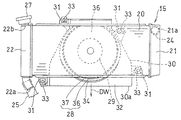
- 2 and 3 are a front view and a longitudinal sectional view of the radiator 15, respectively.
- the radiator 15 has a horizontally long rectangular shape when viewed from the front, and has a core 20 that allows a cooling medium to flow horizontally in a plurality of horizontal fins.
- a cooling medium introduction tank 21 is provided at the right end (left side of the vehicle body) of the core 20, and a cooling medium outlet tank 22 is provided at the left end (right side of the vehicle body). That is, the radiator 15 of this embodiment is a cross flow type.
- the type of the radiator is not limited to this, and for example, the core 20 may be a vertical type in which a cooling medium flows in the vertical direction.
- “left side” and “right side” refer to the left and right sides of the vehicle body, that is, the left and right sides as viewed from the driver who rides the motorcycle.
- the introduction tank 21 introduces a high-temperature cooling medium discharged from the cylinder head 19 of the engine E in FIG. 1 and guides it to the core 20 in FIG.
- a cylindrical cooling medium inlet 21a is provided at the upper end of the introduction tank 21, and an introduction hose 24 for introducing a high-temperature cooling medium from the cylinder head 19 (FIG. 1) is connected to the cooling medium inlet 21a.
- the outlet tank 22 of the radiator 15 guides the coolant that has passed through the core 20 and has become low temperature to the engine E side.
- a cylindrical cooling medium outlet 22a is provided at the lower end of the outlet tank 22, and an outlet hose 25 is connected to the cooling medium outlet 22a.
- a replenishing port 22b for replenishing the cooling medium is provided at the upper end of the lead-out tank 22, and the replenishing port 22b is normally closed with a cap 27.
- a cooling fan 28 that ventilates the core 20 and an electric motor 29 that drives the cooling fan 28 are disposed on the back side of the core 20 of the radiator 15.
- the cooling fan 28 is obtained by covering the outer periphery of the rotary blade 36 connected to the electric motor 29 with a fan housing 37, but the fan housing 37 may be omitted.
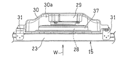
- the cooling fan 28 and the electric motor 29 are covered with a fan cover 30 having an opening 30a below the upper side, both sides, and the downstream side (rear side).
- a partition wall 32 that partitions the lower portion of the core 20 and the lower portion of the cooling fan 28 is provided radially outward of the front portion of the cooling fan 28.
- the partition wall 32 suppresses the exhaust air DW from the opening 30 a from flowing backward to the core 20.
- the axial position of the front surface of the partition wall 32 substantially matches the front surface of the rotary blade 36 of the cooling fan 28.
- the core 20 is supported by a rectangular frame body 20b that covers the periphery of the plurality of fins when viewed from the front, and the partition wall 32 projects downward from the lower surface of the frame body 20b.
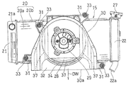
- the fan cover 30 is attached to the frame body 20b of the core 20 by screws through a plurality of attachment pieces 31 provided on the outer periphery thereof.
- the fan cover 30, the partition wall 32, and the attachment piece 31 are made of, for example, resin and are integrally formed by molding.
- the fan cover 30 has a generally inverted U shape with a narrow upper part and a wide lower part as viewed from the direction of the axis C of the cooling fan 28.
- the introduction tank 21 on the left side of the radiator 15 is attached to the second frame piece 1b on the left side of the main frame 1 via a plate-like left attachment piece 35L.
- the right lead-out tank 22 of the radiator 15 is attached to the right second frame piece 1b via a plate-like right attachment piece 35R.
- the cooling fan 28 is covered with a fan housing 37.
- the electric motor 29 is disposed behind the cooling fan 28, and the cooling fan 28 and the electric motor 29 are covered with a fan cover 30.
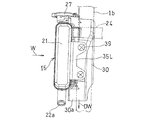
- FIG. 7 which is a side view seen from the left side of the vehicle body
- the left mounting piece 35L is welded to the introduction tank 21 of the radiator 15, and the left mounting piece 35L is connected to the second
- the frame piece 1b is detachably attached.
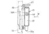
- FIG. 8 which is a side view seen from the right side of the vehicle body
- a right mounting piece 35R is welded to the right second frame piece 1b, and the right mounting piece 35R is attached to the right side of the radiator 15 by a single screw body 40.
- the lead-out tank 22 is detachably attached.
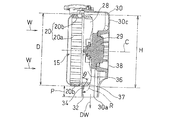
- a guide portion 34 is formed on the outer periphery of the cooling fan 28 in the partition wall 32, that is, in the fan proximity region close to the outer periphery of the fan housing 37.
- the guide portion 34 is inclined toward the downstream side toward the radially inner side of the cooling fan 28 so as to guide air to the outer periphery of the fan housing 37 of the cooling fan 28.
- the guide portion 34 is provided to face the outer periphery of the lower half of the cooling fan 28.
- the inclination angle ⁇ with respect to the plane orthogonal to the axis C of the guide portion 34, that is, the cooling fan front surface is preferably 30 to 60 °, and more preferably 40 to 50 °.
- the length P projecting downward from the core 20 of the partition wall 32 is 0.1 to 0.3 times, preferably 0.15 to 0.25 times the vertical length H of the core 20.
- the protrusion length P is less than 0.1 times H, a sufficient backflow prevention effect of the exhaust air DW cannot be obtained.
- the protrusion length P is 0.3 times that of H, the effect of preventing the backflow is sufficient, and when it exceeds 0.3 times, the entire radiator 15 including the fan cover becomes larger than necessary.
- the rear wall 30 c on the downstream side of the fan cover 30 that covers the cooling fan 28 from the downstream side is orthogonal to the axis C of the cooling fan 28.
- the radiator 15 is covered with a fan cover 30 that opens downward, on both sides and downstream of the cooling fan 28 that ventilates the core 20. Therefore, the exhaust air DW passing through the core 20 and the cooling fan 28 of the radiator 15 is reliably discharged downward from the lower opening 30a of the fan cover 30. This prevents the rider from being exposed to the exhaust air DW.
- the partition wall 32 protrudes downward from the core 20, the exhaust air DW is reliably prevented from entering the lower portion of the radiator 15, and a part of the exhaust air DW is prevented from flowing backward in front of the radiator 15. It can be blocked more effectively.
- the outer diameter D of the cooling fan 28 is increased so as to be substantially the same as the vertical length H of the core 20, even when the traveling wind W is not sufficiently utilized, such as when traveling at a low speed or when stopping, the core 20 It is possible to improve heat dissipation efficiency by introducing air to the main part. Further, since the length P of the fan cover 30 protruding downward from the core 20 is as short as 0.1 to 0.3 times the vertical length H of the core 20, the fan cover 30 does not become larger than necessary. Therefore, the enlargement of the entire radiator 15 including the fan cover 30 is suppressed.
- the speed of the exhaust air DW from the cooling fan 28 of the radiator 15 is suppressed from decreasing due to loss due to friction with the inner surface of the fan cover 30, and the exhaust air DW is reduced.
- the air can be smoothly discharged from the opening 30a below the fan cover 30.
- a guide portion 34 is formed in a fan proximity region facing the outer periphery of the cooling fan 28 in the partition wall 32, and air is guided along the guide portion 34 to the outer periphery of the fan housing 37 of the cooling fan 28. Therefore, even if the exhaust air DW passes over the partition wall 32 and goes below the core 20, it is guided to the outer periphery of the fan housing 37 together with the air. As a result, the exhaust air DW is quickly discharged from the lower opening 30a of the fan cover 30 without passing through the cooling fan 28 again.
- the guide part 34 is provided facing the outer periphery of the lower half of the cooling fan 28, the exhaust air DW exhausted downward from the cooling fan 28 while the fan cover 30 is miniaturized as much as possible. It is possible to suppress backflowing forward.
- the fan cover 30 is attached to the core 20 via an attachment piece 31, and the fan cover 30, the partition wall 32, and the attachment piece 31 are integrally formed. Thereby, the handleability is improved by reducing the number of parts, and the fan cover 30 can be easily attached to the core 20.
- the rear wall 30c that covers the cooling fan 28 shown in FIG. 3 from the downstream side is orthogonal to the axis C of the cooling fan. Accordingly, the upper portion of the fan outlet space is compared with the case of forming a so-called widening fan outlet space in which the rear wall 30c is inclined backward from the upper side to the lower side in order to smooth the exhaust air DW downward. Therefore, the exhaust wind DW can be smoothly discharged from the lower opening 30 a of the fan cover 30. In addition, the upper portion of the core 20 is sufficiently ventilated, and the heat dissipation efficiency of the radiator 15 is improved.
- the motorcycle is exemplified as the saddle riding type vehicle.
- the present invention can be similarly applied to a saddle riding type vehicle even if it is a three-wheel or four-wheel rough terrain vehicle.
- An electric motor may be used as the prime mover. Therefore, such a thing is also included in the scope of the present invention.
Abstract
Provided is a radiator for a saddled vehicle, the radiator being configured so that discharge air which has passed through the fan of the radiator and has been discharged downward from the fan is kept from flowing backward ahead of the vehicle body, thereby preventing the heat radiation efficiency from decreasing.
A radiator (15) for a two-wheeled motor vehicle is provided with: a core (20) through which a coolant flows; a cooling fan (28) disposed downstream of the core (20) and causing air to flow through the core (20); a fan cover (30) for covering the cooling fan (28) from above, from both sides, and from the downstream side and open downward; and a partition wall (32) for separating the lower part of the core (20) and the lower part of the cooling fan (28) to prevent discharge air flow (DW), which flows from the opening (30a), from flowing backward to the core (20).
Description
この出願は、2014年4月15日出願の特願2014-083378の優先権を主張するものであり、その全体を参照により本願の一部をなすものとして引用する。
This application claims the priority of Japanese Patent Application No. 2014-083378 filed on April 15, 2014, and is incorporated herein by reference in its entirety.
本発明は、例えば自動二輪車のような鞍乗型車両に搭載されて、エンジンの冷却媒体を放熱させるラジエータに関する。
The present invention relates to a radiator that is mounted on a straddle-type vehicle such as a motorcycle and radiates heat from an engine coolant.
自動二輪車のような鞍乗型車両に搭載されるラジエータとして、ラジエータの放熱用のコアに走行風の下流側から近接して配設された電動ファンと、この電動ファンを覆うシュラウドとを備えた構造のものがある(例えば特許文献1)。特許文献1のシュラウドは、電動ファンを、走行風の下流側から覆うとともに、その上方から両側方にかけても覆い、下方に開口している。
As a radiator mounted on a saddle riding type vehicle such as a motorcycle, an electric fan disposed close to the radiator heat dissipation core from the downstream side of the traveling wind and a shroud covering the electric fan are provided. There exists a thing of a structure (for example, patent document 1). The shroud of Patent Document 1 covers the electric fan from the downstream side of the traveling wind and also covers the electric fan from the upper side to the both sides and opens downward.
上記特許文献1のラジエータによれば、ラジエータのコアからの排風(熱風)がシュラウドの下方開口から電動ファンの下方に排出されるので、ライダーが排風に曝されることによる不快感が少なくなる。
According to the radiator disclosed in Patent Document 1, exhaust air (hot air) from the core of the radiator is discharged from the lower opening of the shroud to the lower side of the electric fan, so there is less discomfort due to the rider being exposed to the exhaust air. Become.
しかしながら、特許文献1のラジエータでは、ラジエータの電動ファンを通過した排風は、電動ファンの下方へ排出されるが、排風の一部が、コアの下方を通って車体の前方に逆流し、ラジエータから再度吸い込まれる場合がある。高温の排風がラジエータに再度吸い込まれると、ラジエータの放熱効率が低下する。
However, in the radiator of Patent Document 1, exhaust air that has passed through the electric fan of the radiator is discharged to the lower side of the electric fan, but a part of the exhaust air flows backward to the front of the vehicle body under the core, May be sucked in again from the radiator. When the high-temperature exhaust air is sucked into the radiator again, the heat dissipation efficiency of the radiator decreases.
本発明の目的は、ラジエータのファンを通過してファンの下方へ排出された排風をラジエータのコアの前方に逆流させないことで、放熱効率が低下しない鞍乗型車両のラジエータを提供することにある。
SUMMARY OF THE INVENTION An object of the present invention is to provide a radiator for a saddle-ride type vehicle in which heat dissipation efficiency does not decrease by preventing the exhaust air that has passed through the fan of the radiator and discharged to the lower side of the fan from flowing backward to the front of the core of the radiator. is there.
前記目的を達成するために、本発明に係る鞍乗型車両のラジエータは、鞍乗型車両に搭載される原動機の冷却媒体を放熱させるラジエータであって、前記冷却媒体を流すコアと、その下流側に配設されて前記コアに通風する冷却ファンと、前記冷却ファンの上方、両側方および下流側を覆い、下方に開口したファンカバーと、前記コアの下部と前記冷却ファンの下部との間を仕切って前記開口からの排風が前記コアに逆流するのを抑制する仕切り壁とを備えている。
In order to achieve the above object, a radiator of a saddle riding type vehicle according to the present invention is a radiator that dissipates heat from a cooling medium of a prime mover mounted on the saddle riding type vehicle, and a core through which the cooling medium flows and a downstream thereof A cooling fan disposed on the side and ventilating the core; a fan cover that covers the upper side, both sides, and the downstream side of the cooling fan; and opens downward; and a space between the lower part of the core and the lower part of the cooling fan And a partition wall that suppresses the exhaust air from the opening from flowing back to the core.
この構成によれば、ラジエータの冷却ファンを通過した排風が、ファンカバーの下方の開口から排出されるとき、排風の一部が、ラジエータの前方に逆流しようとしても、仕切り壁によって、その逆流が阻止され、ラジエータから再度吸い込まれることがない。したがって、排風をファンカバーの下方開口から下方に向かって円滑に排出できるので、ライダーが排風に曝される不快感がないのはもとより、ラジエータの放熱効率が低下するのを抑制できる。
According to this configuration, when the exhaust air that has passed through the cooling fan of the radiator is exhausted from the opening below the fan cover, even if a part of the exhaust air flows back to the front of the radiator, the partition wall Backflow is prevented and it is not sucked again from the radiator. Therefore, since the exhaust air can be smoothly discharged downward from the lower opening of the fan cover, it is possible to suppress a reduction in the heat dissipation efficiency of the radiator as well as no discomfort for the rider to be exposed to the exhaust air.
本発明のラジエータにおいて、前記仕切り壁は前記コアよりも下方に突出していることが好ましい。この構成によれば、排風がラジエータの下方に回り込むのを確実に阻止されるので、排風の一部がラジエータの前方に逆流するのを一層効率的に阻止することができる。
In the radiator of the present invention, it is preferable that the partition wall protrudes downward from the core. According to this configuration, since the exhaust air is reliably prevented from flowing downwardly of the radiator, it is possible to more efficiently prevent a part of the exhaust air from flowing backward to the front of the radiator.
本発明のラジエータにおいて、前記冷却ファンの外径Dは前記コアの上下長さHとほぼ同一であり、前記ファンカバーのコアから下方への突出長さPは、前記コアの前記上下長さHの0.1~0.3倍であることが好ましい。この構成によれば、ファン外径Dをコア上下長さHとほぼ同一になるように大きくしたので、低速走行時もしくは停車時のような、走行風を十分に利用できない状況でも、コアの主要部に導風して放熱効率を向上させることができる。また、突出長さP=0.1~0.3Hとしたから、ファンカバーの寸法が必要以上に大きくならない。したがって、ファンカバーを含むラジエータ全体の大形化が抑制されるとともに、ラジエータの冷却ファンからの排風の速度を、ファンカバー内面との摩擦損失によって低下させるのを抑制しながら、円滑にファンカバーの下方の開口から排出させることができる。
In the radiator according to the present invention, the outer diameter D of the cooling fan is substantially the same as the vertical length H of the core, and the protruding length P of the fan cover downward from the core is the vertical length H of the core. Is preferably 0.1 to 0.3 times. According to this configuration, the fan outer diameter D is increased so as to be substantially the same as the length H of the core. Therefore, even when the traveling wind cannot be used sufficiently, such as when driving at low speed or when stopping, The heat radiation efficiency can be improved by introducing air to the part. Further, since the protrusion length P is set to 0.1 to 0.3H, the size of the fan cover does not become larger than necessary. Therefore, the size of the entire radiator including the fan cover is suppressed, and the fan cover can be smoothly smoothed while suppressing the speed of exhaust air from the cooling fan of the radiator from being reduced by friction loss with the fan cover inner surface. It can be discharged from the opening below.
本発明のラジエータにおいて、前記仕切り壁における前記冷却ファンの外周に対向するファン近接領域に、前記排風を前記冷却ファンのファンハウジングの外周に導くように前記冷却ファンの径方向内側に向かって下流側へ傾斜するガイド部が形成されていることが好ましい。前記冷却ファンの前面に対する前記ガイド部の傾斜角度θは、例えば、30~60°である。この構成によれば、排風をガイド部に沿わせて冷却ファンのファンハウジングの外周に導くことができ、ファンハウジングの外周に導かれた排風は、冷却ファンを再度通過することなく、ファンカバーの下方開口から速やかに排出できる。
In the radiator according to the aspect of the invention, the exhaust air is downstream in the radially inner side of the cooling fan so as to guide the exhaust air to the outer periphery of the fan housing of the cooling fan in the fan proximity region of the partition wall facing the outer periphery of the cooling fan. It is preferable that the guide part which inclines to the side is formed. The inclination angle θ of the guide portion with respect to the front surface of the cooling fan is, for example, 30 to 60 °. According to this configuration, the exhaust air can be guided to the outer periphery of the fan housing of the cooling fan along the guide portion, and the exhaust air guided to the outer periphery of the fan housing does not pass through the cooling fan again. It can be quickly discharged from the lower opening of the cover.
本発明のラジエータにおいて、さらに、前記ガイド部は、前記冷却ファンの下半分の外周に対向して設けられていることが好ましい。この構成によれば、ファンカバーを極力小形化しながら冷却ファンから下方へ排出される排風がコアの前方へ逆流するのを抑制できる。
In the radiator according to the aspect of the invention, it is preferable that the guide portion is provided to face an outer periphery of a lower half of the cooling fan. According to this configuration, it is possible to suppress the exhaust air discharged downward from the cooling fan from flowing backward to the front of the core while miniaturizing the fan cover as much as possible.
本発明のラジエータにおいて、前記ファンカバーは前記コアに取付片を介して取り付けられており、前記ファンカバー、前記仕切り壁および前記取付片が一体成形物であることが好ましい。この構成によれば、部品点数の削減により取扱性が向上し、コアに対するファンカバーの取付も簡便に行える。
In the radiator of the present invention, it is preferable that the fan cover is attached to the core via an attachment piece, and the fan cover, the partition wall, and the attachment piece are integrally formed. According to this configuration, the handleability is improved by reducing the number of parts, and the fan cover can be easily attached to the core.
本発明のラジエータにおいて、前記冷却ファンを下流側から覆う後壁は、前記冷却ファンの軸心と直交していることが好ましい。この構成によれば、下方への排風を円滑化するために後壁を上方から下方へ向かって後方へ傾斜させる、いわゆる末広がりのファン出口空間を形成する場合と比較して、ファン出口空間の上部の前記軸心方向の寸法、つまり、ファンカバーの上部の奥行きが広がるので、コアの上部が十分に通風されて、放熱効率が向上する。
In the radiator of the present invention, it is preferable that a rear wall that covers the cooling fan from the downstream side is orthogonal to the axis of the cooling fan. According to this configuration, compared with the case of forming a so-called wide fan outlet space in which the rear wall is inclined backward from the upper side to the lower side in order to smooth the exhaust air downward, the fan outlet space Since the dimension of the upper part in the axial direction, that is, the depth of the upper part of the fan cover increases, the upper part of the core is sufficiently ventilated to improve the heat radiation efficiency.
本発明のラジエータにおいて、前記ファンカバーは、前記冷却ファンの軸心の方向から見て、上部が幅狭で下部が幅広の概ね逆U字形であることが好ましい。この構成によれば、上方から下方へ向かって幅方向に広がるファン出口空間が形成されるので、下方への排風が円滑になる。
In the radiator according to the aspect of the invention, it is preferable that the fan cover has a generally inverted U shape with a narrow upper portion and a wide lower portion as viewed from the axial center of the cooling fan. According to this configuration, the fan outlet space that extends in the width direction from the upper side to the lower side is formed, so that the downward air discharge becomes smooth.
請求の範囲および/または明細書および/または図面に開示された少なくとも2つの構成のどのような組合せも、本発明に含まれる。特に、請求の範囲の各請求項の2つ以上のどのような組合せも、本発明に含まれる。
Any combination of at least two configurations disclosed in the claims and / or the specification and / or drawings is included in the present invention. In particular, any combination of two or more of each claim in the claims is included in the present invention.
本発明は、添付の図面を参考にした以下の好適な実施形態の説明からより明瞭に理解されるであろう。しかしながら、実施形態および図面は単なる図示および説明のためのものであり、本発明の範囲を定めるために利用されるべきものではない。本発明の範囲は添付の請求の範囲によって定まる。添付図面において、複数の図面における同一の部品番号は、同一または相当部分を示す。
本発明の好ましい実施形態に係るラジエータを備えた自動二輪車の前半部を示す側面図である。
同ラジエータを前方側から見た正面図である。
同ラジエータの縦断面図である。
同ラジエータを後方側から見た背面図である。
同ラジエータの平面図である。
同ラジエータの底面図である。
同ラジエータを車体の左側から見た側面図である。
同ラジエータを車体の右側から見た側面図である。
The present invention will be more clearly understood from the following description of preferred embodiments with reference to the accompanying drawings. However, the embodiments and drawings are for illustration and description only and should not be used to define the scope of the present invention. The scope of the invention is defined by the appended claims. In the accompanying drawings, the same part numbers in a plurality of drawings indicate the same or corresponding parts.
1 is a side view showing a front half portion of a motorcycle including a radiator according to a preferred embodiment of the present invention. It is the front view which looked at the same radiator from the front side. It is a longitudinal cross-sectional view of the same radiator. It is the rear view which looked at the same radiator from the back side. It is a top view of the same radiator. It is a bottom view of the same radiator. It is the side view which looked at the same radiator from the left side of the body. It is the side view which looked at the same radiator from the right side of a vehicle body.
以下、本発明の好ましい実施形態について図面を参照しながら説明する。図1は本発明の好ましい実施形態に係るラジエータを適用した自動二輪車の前半部を示す。図1において、本発明の自動二輪車は、車体フレームFRの前半部を形成するメインフレーム1と、後半部を形成するリヤフレーム12とを有している。メインフレーム1の前端にフロントフォーク2が支持され、このフロントフォーク2の下端部に設けたボトムケース3に、前輪4が、車軸5を介して支持されている。
Hereinafter, preferred embodiments of the present invention will be described with reference to the drawings. FIG. 1 shows a front half of a motorcycle to which a radiator according to a preferred embodiment of the present invention is applied. In FIG. 1, the motorcycle of the present invention has a main frame 1 that forms the front half of the vehicle body frame FR and a rear frame 12 that forms the rear half. A front fork 2 is supported at the front end of the main frame 1, and a front wheel 4 is supported via an axle 5 on a bottom case 3 provided at the lower end of the front fork 2.
フロントフォーク2は、これを支持するアッパブラケット6およびロワブラケット7とともに、メインフレーム1の前端のヘッドパイプ8に回動自在に支持されており、アッパブラケット6にハンドル10が取り付けられている。一方、メインフレーム1の後端下部には、スイングアームブラケット11が固着され、このスイングアームブラケット11に、図示しない後輪を支持するスイングアームが揺動自在に軸支されている。メインフレーム1の中央下部には後輪を駆動する原動機であるエンジンEが支持されている。
The front fork 2 is rotatably supported by a head pipe 8 at the front end of the main frame 1 together with an upper bracket 6 and a lower bracket 7 that support the front fork 2, and a handle 10 is attached to the upper bracket 6. On the other hand, a swing arm bracket 11 is fixed to the lower portion of the rear end of the main frame 1, and a swing arm that supports a rear wheel (not shown) is pivotally supported by the swing arm bracket 11 so as to be swingable. An engine E, which is a prime mover for driving the rear wheels, is supported at the lower center of the main frame 1.
メインフレーム1は、前後方向に延びたのち屈曲して下方に延びる左右一対の第1フレーム片1a,1a、第1フレーム片1aの前部でヘッドパイプ8の後方近傍に上端部が接合された左右一対の第2フレーム片1b、1b、第2フレーム片1bの下端部と第1フレーム片1aの屈折部との間に接合された第3フレーム片1c、および前傾姿勢の第2フレーム片1b,1bの上下方向中間部と第1フレーム片1aにおける中間の屈曲部よりも前方部分とに両端が接合された左右一対の第4フレーム片1dを備えている。
The main frame 1 has a pair of left and right first frame pieces 1a, 1a that extend in the front-rear direction and then bend and extend downward. The upper end of the main frame 1 is joined to the rear of the head pipe 8 at the front part of the first frame piece 1a. A pair of left and right second frame pieces 1b and 1b, a third frame piece 1c joined between a lower end portion of the second frame piece 1b and a refracting portion of the first frame piece 1a, and a second frame piece in a forward inclined posture. A pair of left and right fourth frame pieces 1d having both ends joined to an intermediate portion in the vertical direction of 1b and 1b and a front portion of an intermediate bent portion of the first frame piece 1a are provided.
リヤフレーム12は、その上部に、第1フレーム片1a,1aに連結された左右一対のシートレール12aを有し、これらシートレール12aにライダーシート13と同乗者用の後部シート(図示せず)とが支持されている。メインフレーム1の前部における前輪4の後方斜め上方には、エンジンEの冷却媒体を放熱するラジエータ15が取り付けられている。冷却媒体は、例えば、冷却水である。
The rear frame 12 has a pair of left and right seat rails 12a connected to the first frame pieces 1a, 1a at an upper portion thereof, and a rider's seat 13 and a passenger's rear seat (not shown) are attached to the seat rails 12a. And are supported. A radiator 15 that dissipates the cooling medium of the engine E is attached to the front of the main frame 1 diagonally above and behind the front wheels 4. The cooling medium is, for example, cooling water.
ラジエータ15は、エンジンEと同様に、その上端部が下端部よりも前方に位置する前傾姿勢であり、空車状態で鉛直方向に対し、10~20°、図1では15°傾斜している。傾斜したラジエータ15は、側面視で第2フレーム片1bおよびエンジンEのシリンダ軸心C1と平行である。メインフレーム1の上部、つまり、車体上部には、ヘッドパイプ8とライダーシート13との間に位置して、燃料タンク18が支持されている。
Like the engine E, the radiator 15 has a forward leaning posture with its upper end positioned forward of the lower end, and is inclined 10 to 20 ° with respect to the vertical direction in an empty state, and 15 ° in FIG. . The inclined radiator 15 is parallel to the second frame piece 1b and the cylinder axis C1 of the engine E in a side view. A fuel tank 18 is supported at the upper part of the main frame 1, that is, at the upper part of the vehicle body, between the head pipe 8 and the rider seat 13.
つぎに、図2~図8によりラジエータ15の詳細について説明する。これらの図は、ラジエータ15に冷却ファン28およびファンカバー30をアセンブリした状態を示す。図2および図3は、それぞれ、ラジエータ15の正面図および縦断面図である。
Next, details of the radiator 15 will be described with reference to FIGS. These drawings show a state in which the cooling fan 28 and the fan cover 30 are assembled to the radiator 15. 2 and 3 are a front view and a longitudinal sectional view of the radiator 15, respectively.
図2に示すように、ラジエータ15は正面視で横長の矩形状であり、水平な複数のフィン内に冷却媒体を水平方向に流すコア20を有している。コア20の右端(車体の左側)に冷却媒体の導入タンク21が設けられ、左端(車体の右側)に冷却媒体の導出タンク22が設けられている。つまり、本実施形態のラジエータ15は、クロスフロータイプである。ラジエータの形式はこれに限定されず、例えば、コア20は上下方向に冷却媒体を流すバーチカルタイプであってもよい。以下の説明において、「左側」および「右側」は、車体の左右側、つまり、自動二輪車に乗車した運転者から見た左右側をいう。
As shown in FIG. 2, the radiator 15 has a horizontally long rectangular shape when viewed from the front, and has a core 20 that allows a cooling medium to flow horizontally in a plurality of horizontal fins. A cooling medium introduction tank 21 is provided at the right end (left side of the vehicle body) of the core 20, and a cooling medium outlet tank 22 is provided at the left end (right side of the vehicle body). That is, the radiator 15 of this embodiment is a cross flow type. The type of the radiator is not limited to this, and for example, the core 20 may be a vertical type in which a cooling medium flows in the vertical direction. In the following description, “left side” and “right side” refer to the left and right sides of the vehicle body, that is, the left and right sides as viewed from the driver who rides the motorcycle.
導入タンク21は、図1のエンジンEのシリンダヘッド19から排出された高温の冷却媒体を導入して、図2のコア20に導くものである。導入タンク21の上端部に円筒状の冷却媒体入口21aが設けられ、この冷却媒体入口21aに、シリンダヘッド19(図1)からの高温の冷却媒体を導入する導入ホース24が接続される。
The introduction tank 21 introduces a high-temperature cooling medium discharged from the cylinder head 19 of the engine E in FIG. 1 and guides it to the core 20 in FIG. A cylindrical cooling medium inlet 21a is provided at the upper end of the introduction tank 21, and an introduction hose 24 for introducing a high-temperature cooling medium from the cylinder head 19 (FIG. 1) is connected to the cooling medium inlet 21a.
ラジエータ15の導出タンク22は、コア20を通過して低温となった冷却媒体をエンジンE側に導くものである。導出タンク22の下端部には円筒状の冷却媒体出口22aが設けられ、この冷却媒体出口22aに導出ホース25が接続される。また、導出タンク22の上端部には冷却媒体を補給する補給口22bが設けられ、通常時は、補給口22bはキャップ27で閉蓋されている。
The outlet tank 22 of the radiator 15 guides the coolant that has passed through the core 20 and has become low temperature to the engine E side. A cylindrical cooling medium outlet 22a is provided at the lower end of the outlet tank 22, and an outlet hose 25 is connected to the cooling medium outlet 22a. A replenishing port 22b for replenishing the cooling medium is provided at the upper end of the lead-out tank 22, and the replenishing port 22b is normally closed with a cap 27.
図3に示すように、ラジエータ15のコア20の背面側には、コア20に通風する冷却ファン28と、この冷却ファン28を駆動する電動モータ29とが配設されている。冷却ファン28は、電動モータ29に連結された回転羽根36の外周をファンハウジング37で覆ったものであるが、ファンハウジング37は割愛される場合がある。これら冷却ファン28および電動モータ29は、その上方、両側方および下流側(後方)が、下方に開口30aを有するファンカバー30により覆われている。
As shown in FIG. 3, a cooling fan 28 that ventilates the core 20 and an electric motor 29 that drives the cooling fan 28 are disposed on the back side of the core 20 of the radiator 15. The cooling fan 28 is obtained by covering the outer periphery of the rotary blade 36 connected to the electric motor 29 with a fan housing 37, but the fan housing 37 may be omitted. The cooling fan 28 and the electric motor 29 are covered with a fan cover 30 having an opening 30a below the upper side, both sides, and the downstream side (rear side).
冷却ファン28の前部の径方向外方には、コア20の下部と冷却ファン28の下部との間を仕切る仕切り壁32が設けられている。仕切り壁32は、開口30aからの排風DWがコア20に逆流するのを抑制する。仕切り壁32の前面の軸方向位置は、冷却ファン28の回転羽根36の前面とほぼ合致している。コア20は、複数のフィンの周囲を覆う正面視で矩形の枠体20bによって支持されており、仕切り壁32は枠体20bの下面よりも下方に突出している。
A partition wall 32 that partitions the lower portion of the core 20 and the lower portion of the cooling fan 28 is provided radially outward of the front portion of the cooling fan 28. The partition wall 32 suppresses the exhaust air DW from the opening 30 a from flowing backward to the core 20. The axial position of the front surface of the partition wall 32 substantially matches the front surface of the rotary blade 36 of the cooling fan 28. The core 20 is supported by a rectangular frame body 20b that covers the periphery of the plurality of fins when viewed from the front, and the partition wall 32 projects downward from the lower surface of the frame body 20b.
図4の背面図に示すように、ファンカバー30は、その外周に設けた複数の取付片31を介してコア20の枠体20bにねじ止めにより取り付けられている。ファンカバー30と仕切り壁32および取付片31は、例えば樹脂製で、型成形により一体成形されている。ファンカバー30は、冷却ファン28の軸心Cの方向から見て、上部が幅狭で下部が幅広の概ね逆U字形を呈している。
As shown in the rear view of FIG. 4, the fan cover 30 is attached to the frame body 20b of the core 20 by screws through a plurality of attachment pieces 31 provided on the outer periphery thereof. The fan cover 30, the partition wall 32, and the attachment piece 31 are made of, for example, resin and are integrally formed by molding. The fan cover 30 has a generally inverted U shape with a narrow upper part and a wide lower part as viewed from the direction of the axis C of the cooling fan 28.
図5の平面図に示すように、ラジエータ15の左側の導入タンク21が、メインフレーム1の左側の第2フレーム片1bに、板状の左側取付片35Lを介して取り付けられている。一方、ラジエータ15の右側の導出タンク22は、右側の第2フレーム片1bに、板状の右側取付片35Rを介して取り付けられている。
As shown in the plan view of FIG. 5, the introduction tank 21 on the left side of the radiator 15 is attached to the second frame piece 1b on the left side of the main frame 1 via a plate-like left attachment piece 35L. On the other hand, the right lead-out tank 22 of the radiator 15 is attached to the right second frame piece 1b via a plate-like right attachment piece 35R.
図6の底面図に明示するように、冷却ファン28はファンハウジング37によって覆われている。この冷却ファン28の背後には前記電動モータ29が配設されており、これら冷却ファン28および電動モータ29がファンカバー30で覆われている。
As clearly shown in the bottom view of FIG. 6, the cooling fan 28 is covered with a fan housing 37. The electric motor 29 is disposed behind the cooling fan 28, and the cooling fan 28 and the electric motor 29 are covered with a fan cover 30.
車体左側から見た側面図である図7に示すように、ラジエータ15の導入タンク21に左側取付片35Lが溶接され、この左側取付片35Lが上下2つのねじ体39,39により左側の第2フレーム片1bに着脱自在に取り付けられている。車体右側から見た側面図である図8に示すように、右側の第2フレーム片1bに右側取付片35Rが溶接され、この右側取付片35Rが単一のねじ体40によりラジエータ15の右側の導出タンク22に着脱自在に取り付けられている。
As shown in FIG. 7 which is a side view seen from the left side of the vehicle body, the left mounting piece 35L is welded to the introduction tank 21 of the radiator 15, and the left mounting piece 35L is connected to the second The frame piece 1b is detachably attached. As shown in FIG. 8 which is a side view seen from the right side of the vehicle body, a right mounting piece 35R is welded to the right second frame piece 1b, and the right mounting piece 35R is attached to the right side of the radiator 15 by a single screw body 40. The lead-out tank 22 is detachably attached.
図3に示すように、仕切り壁32における冷却ファン28の外周、つまり、ファンハウジング37の外周に近接するファン近接領域に、ガイド部34が形成されている。ガイド部34は、空気を冷却ファン28のファンハウジング37の外周に導くように、冷却ファン28の径方向内側に向かって下流側へ傾斜している。このガイド部34は、図4に示すように、冷却ファン28の下半分の外周に対向して設けられている。図3に示すように、ガイド部34の軸心Cと直交する面、つまり冷却ファン前面に対する傾斜角度θは、30~60°が好ましく、40~50°がより好ましい。
As shown in FIG. 3, a guide portion 34 is formed on the outer periphery of the cooling fan 28 in the partition wall 32, that is, in the fan proximity region close to the outer periphery of the fan housing 37. The guide portion 34 is inclined toward the downstream side toward the radially inner side of the cooling fan 28 so as to guide air to the outer periphery of the fan housing 37 of the cooling fan 28. As shown in FIG. 4, the guide portion 34 is provided to face the outer periphery of the lower half of the cooling fan 28. As shown in FIG. 3, the inclination angle θ with respect to the plane orthogonal to the axis C of the guide portion 34, that is, the cooling fan front surface is preferably 30 to 60 °, and more preferably 40 to 50 °.
ファンハウジング37を含めた冷却ファン28の外径Dは、コア20の上下長さHとほぼ同一、すなわち、D=0.9~1.1Hであるが、外径Dを小さくして、D=0.7~0.9程度としてもよい。仕切り壁32のコア20から下方への突出長さPは、コア20の上下長さHの0.1~0.3倍であり、好ましくは0.15~0.25倍である。突出長さPがHの0.1倍未満では、排風DWの十分な逆流防止効果が得られない。突出長さPがHの0.3倍で逆流防止効果は十分となり、0.3倍を超えると、ファンカバーを含むラジエータ15全体が必要以上に大形化する。また、冷却ファン28を下流側から覆うファンカバー30の下流側である後壁30cは、冷却ファン28の軸心Cと直交している。
The outer diameter D of the cooling fan 28 including the fan housing 37 is substantially the same as the vertical length H of the core 20, that is, D = 0.9 to 1.1H. It may be about 0.7 to 0.9. The length P projecting downward from the core 20 of the partition wall 32 is 0.1 to 0.3 times, preferably 0.15 to 0.25 times the vertical length H of the core 20. When the protrusion length P is less than 0.1 times H, a sufficient backflow prevention effect of the exhaust air DW cannot be obtained. When the protrusion length P is 0.3 times that of H, the effect of preventing the backflow is sufficient, and when it exceeds 0.3 times, the entire radiator 15 including the fan cover becomes larger than necessary. Further, the rear wall 30 c on the downstream side of the fan cover 30 that covers the cooling fan 28 from the downstream side is orthogonal to the axis C of the cooling fan 28.
上記構成において、ラジエータ15は、コア20に通風する冷却ファン28の上方、両側方および下流側が、下方に開口したファンカバー30により覆われている。したがって、ラジエータ15のコア20および冷却ファン28を通った排風DWは、確実にファンカバー30の下方開口30aから下方に向かって排出される。これにより、ライダーが排風DWに曝されることがなくなる。
In the above configuration, the radiator 15 is covered with a fan cover 30 that opens downward, on both sides and downstream of the cooling fan 28 that ventilates the core 20. Therefore, the exhaust air DW passing through the core 20 and the cooling fan 28 of the radiator 15 is reliably discharged downward from the lower opening 30a of the fan cover 30. This prevents the rider from being exposed to the exhaust air DW.
また、冷却ファン28を通過した排風DWが、ファンカバー30の下方の開口30aから排出されるとき、排風DWの一部が、車体の前方へ二点鎖線の矢印Rで示すように逆流しようとしても、仕切り壁32によって逆流が阻まれ、前方からコア20内へ再度吸い込まれることがない。したがって、高温の排風DWの巻き込みにより、ラジエータ15の放熱効率が低下することなく、ラジエータ15の本来の性能を十分に発揮させることができる。
Further, when the exhaust air DW that has passed through the cooling fan 28 is exhausted from the opening 30a below the fan cover 30, a part of the exhaust air DW flows backward to the front of the vehicle body as indicated by the two-dot chain line arrow R. Even if an attempt is made, the partition wall 32 prevents the backflow from being sucked into the core 20 again from the front. Therefore, the original performance of the radiator 15 can be sufficiently exhibited without lowering the heat dissipation efficiency of the radiator 15 due to the entrainment of the high temperature exhaust air DW.
また、仕切り壁32はコア20よりも下方に突出しているので、排風DWがラジエータ15の下方に回り込むのを確実に阻止され、排風DWの一部がラジエータ15の前方に逆流するのを一層効果的に阻止することができる。
Further, since the partition wall 32 protrudes downward from the core 20, the exhaust air DW is reliably prevented from entering the lower portion of the radiator 15, and a part of the exhaust air DW is prevented from flowing backward in front of the radiator 15. It can be blocked more effectively.
冷却ファン28の外径Dをコア20の上下長さHとほぼ同一になるように大きくしたので、低速走行時もしくは停車時のような、走行風Wを十分に利用できない状況でも、コア20の主要部に導風して放熱効率を向上させることができる。また、ファンカバー30のコア20から下方への突出長さPは、コア20の上下長さHの0.1~0.3倍と短くしたから、ファンカバー30が必要以上に大形化しないので、ファンカバー30を含むラジエータ15全体の大形化が抑制される。しかも、突出長さPの抑制により、ラジエータ15の冷却ファン28からの排風DWの速度が、ファンカバー30の内面との摩擦に起因する損失によって低下するのを抑制して、排風DWを円滑にファンカバー30の下方の開口30aから排出することができる。
Since the outer diameter D of the cooling fan 28 is increased so as to be substantially the same as the vertical length H of the core 20, even when the traveling wind W is not sufficiently utilized, such as when traveling at a low speed or when stopping, the core 20 It is possible to improve heat dissipation efficiency by introducing air to the main part. Further, since the length P of the fan cover 30 protruding downward from the core 20 is as short as 0.1 to 0.3 times the vertical length H of the core 20, the fan cover 30 does not become larger than necessary. Therefore, the enlargement of the entire radiator 15 including the fan cover 30 is suppressed. In addition, by suppressing the protrusion length P, the speed of the exhaust air DW from the cooling fan 28 of the radiator 15 is suppressed from decreasing due to loss due to friction with the inner surface of the fan cover 30, and the exhaust air DW is reduced. The air can be smoothly discharged from the opening 30a below the fan cover 30.
また、仕切り壁32における冷却ファン28の外周に対向するファン近接領域にガイド部34が形成され、このガイド部34に沿って空気が冷却ファン28のファンハウジング37の外周に導かれる。したがって、排風DWが、仕切り壁32を越えてコア20の下方に回り込んでも、空気とともにファンハウジング37の外周に導かれる。その結果、排風DWは、冷却ファン28を再度通過することなく、ファンカバー30の下方開口30aから速やかに排出される。
In addition, a guide portion 34 is formed in a fan proximity region facing the outer periphery of the cooling fan 28 in the partition wall 32, and air is guided along the guide portion 34 to the outer periphery of the fan housing 37 of the cooling fan 28. Therefore, even if the exhaust air DW passes over the partition wall 32 and goes below the core 20, it is guided to the outer periphery of the fan housing 37 together with the air. As a result, the exhaust air DW is quickly discharged from the lower opening 30a of the fan cover 30 without passing through the cooling fan 28 again.
さらに、ガイド部34は、冷却ファン28の下半分の外周に対向して設けられているので、ファンカバー30を極力小形化しながら、冷却ファン28から下方へ排出される排風DWがコア20の前方へ逆流するのを抑制できる。
Furthermore, since the guide part 34 is provided facing the outer periphery of the lower half of the cooling fan 28, the exhaust air DW exhausted downward from the cooling fan 28 while the fan cover 30 is miniaturized as much as possible. It is possible to suppress backflowing forward.
図4に示すように、ファンカバー30はコア20に取付片31を介して取り付けられており、ファンカバー30、仕切り壁32および取付片31が一体成形物である。これにより、部品点数の削減により取扱性が向上し、コア20に対するファンカバー30の取付も簡便に行える。
As shown in FIG. 4, the fan cover 30 is attached to the core 20 via an attachment piece 31, and the fan cover 30, the partition wall 32, and the attachment piece 31 are integrally formed. Thereby, the handleability is improved by reducing the number of parts, and the fan cover 30 can be easily attached to the core 20.
さらに、図3に示す冷却ファン28を下流側から覆う後壁30cは、冷却ファンの軸心Cと直交している。これにより、下方への排風DWを円滑化するために後壁30cを上方から下方へ向かって後方へ傾斜させる、いわゆる末広がりのファン出口空間を形成する場合と比較して、ファン出口空間の上部の軸心方向の寸法、つまり、ファンカバー30の上部の奥行きが広がるので、ファンカバー30の下方開口30aから排風DWを円滑に排出させることができる。しかも、コア20の上部が十分に通風されて、ラジエータ15の放熱効率が向上する。
Furthermore, the rear wall 30c that covers the cooling fan 28 shown in FIG. 3 from the downstream side is orthogonal to the axis C of the cooling fan. Accordingly, the upper portion of the fan outlet space is compared with the case of forming a so-called widening fan outlet space in which the rear wall 30c is inclined backward from the upper side to the lower side in order to smooth the exhaust air DW downward. Therefore, the exhaust wind DW can be smoothly discharged from the lower opening 30 a of the fan cover 30. In addition, the upper portion of the core 20 is sufficiently ventilated, and the heat dissipation efficiency of the radiator 15 is improved.
以上のとおり、図面を参照しながら好適な実施形態を説明したが、本発明の趣旨を逸脱しない範囲内で、種々の追加、変更または削除が可能である。例えば、鞍乗型車両として、前述した説明では自動二輪車を例示したが、三輪または四輪の不整地走行車両などであっても、鞍乗型車両であれば、本発明を同様に適用できる。また、原動機として電動モータを使用してもよい。したがって、そのようなものも本発明の範囲内に含まれる。
As described above, the preferred embodiments have been described with reference to the drawings, but various additions, changes, or deletions can be made without departing from the spirit of the present invention. For example, in the above description, the motorcycle is exemplified as the saddle riding type vehicle. However, the present invention can be similarly applied to a saddle riding type vehicle even if it is a three-wheel or four-wheel rough terrain vehicle. An electric motor may be used as the prime mover. Therefore, such a thing is also included in the scope of the present invention.
15…ラジエータ
20…コア
28…冷却ファン
29…電動モータ
30…ファンカバー
30a…開口
30c…後壁
31…取付片
32…仕切り壁
34…ガイド部
37…ファンハウジング
C…(電動モータの)軸心
DW…排風
W…走行風 DESCRIPTION OFSYMBOLS 15 ... Radiator 20 ... Core 28 ... Cooling fan 29 ... Electric motor 30 ... Fan cover 30a ... Opening 30c ... Rear wall 31 ... Mounting piece 32 ... Partition wall 34 ... Guide part 37 ... Fan housing C ... Shaft center (electric motor) DW ... exhaust wind W ... running wind
20…コア
28…冷却ファン
29…電動モータ
30…ファンカバー
30a…開口
30c…後壁
31…取付片
32…仕切り壁
34…ガイド部
37…ファンハウジング
C…(電動モータの)軸心
DW…排風
W…走行風 DESCRIPTION OF
Claims (9)
- 鞍乗型車両に搭載される原動機の冷却媒体を放熱させるラジエータであって、
前記冷却媒体を流すコアと、
その下流側に配設されて前記コアに通風する冷却ファンと、
前記冷却ファンの上方、両側方および下流側を覆い、下方に開口したファンカバーと、
前記コアの下部と前記冷却ファンの下部との間を仕切って前記開口からの排風が前記コアに逆流するのを抑制する仕切り壁とを備えた鞍乗型車両のラジエータ。 A radiator that dissipates the cooling medium of a prime mover mounted on a saddle riding type vehicle,
A core through which the cooling medium flows;
A cooling fan disposed downstream thereof and ventilating the core;
A fan cover that covers the upper side, both sides, and the downstream side of the cooling fan and opens downward;
A radiator for a saddle-ride type vehicle, comprising: a partition wall that partitions between a lower portion of the core and a lower portion of the cooling fan and suppresses exhaust air from the opening from flowing backward to the core. - 請求項1に記載のラジエータにおいて、前記仕切り壁は前記コアよりも下方に突出している鞍乗型車両のラジエータ。 2. The radiator according to claim 1, wherein the partition wall projects downward from the core.
- 請求項1または2に記載のラジエータにおいて、前記冷却ファンの外径Dは前記コアの上下長さHとほぼ同一であり、前記ファンカバーのコアから下方への突出長さPは、前記コアの前記上下長さHの0.1~0.3倍である鞍乗型車両のラジエータ。 3. The radiator according to claim 1, wherein an outer diameter D of the cooling fan is substantially the same as a vertical length H of the core, and a protruding length P of the fan cover downward from the core is defined by A saddle-type vehicle radiator having a vertical length H of 0.1 to 0.3 times.
- 請求項1ないし3のいずれか一項に記載のラジエータにおいて、前記仕切り壁における前記冷却ファンの外周に対向するファン近接領域に、前記排風を前記冷却ファンのファンハウジングの外周に導くように前記冷却ファンの径方向内側に向かって下流側へ傾斜するガイド部が形成されている鞍乗型車両のラジエータ。 4. The radiator according to claim 1, wherein the exhaust air is guided to an outer periphery of a fan housing of the cooling fan in a fan proximity region of the partition wall facing the outer periphery of the cooling fan. 5. A radiator for a saddle-ride type vehicle in which a guide portion that is inclined toward a downstream side toward a radially inner side of a cooling fan is formed.
- 請求項4に記載のラジエータにおいて、前記ガイド部は、前記冷却ファンの下半分の外周に対向して設けられている鞍乗型車両のラジエータ。 5. The radiator according to claim 4, wherein the guide portion is provided to face an outer periphery of a lower half of the cooling fan.
- 請求項4または5に記載のラジエータにおいて、前記冷却ファンの前面に対する前記ガイド部の傾斜角度θが30~60°に設定されている鞍乗型車両のラジエータ。 6. The radiator according to claim 4, wherein an inclination angle θ of the guide portion with respect to a front surface of the cooling fan is set to 30 to 60 °.
- 請求項1ないし6のいずれか一項に記載のラジエータにおいて、前記ファンカバーは前記コアに取付片を介して取り付けられており、前記ファンカバー、前記仕切り壁および前記取付片が一体成形物である鞍乗型車両のラジエータ。 7. The radiator according to claim 1, wherein the fan cover is attached to the core via an attachment piece, and the fan cover, the partition wall, and the attachment piece are integrally formed. A radiator for saddle riding type vehicles.
- 請求項1ないし7のいずれか一項に記載のラジエータにおいて、前記冷却ファンを下流側から覆う後壁は、前記冷却ファンの軸心と直交している鞍乗型車両のラジエータ。 8. The radiator according to claim 1, wherein a rear wall that covers the cooling fan from the downstream side is orthogonal to an axis of the cooling fan.
- 請求項1ないし8のいずれか一項に記載のラジエータにおいて、前記ファンカバーは、前記冷却ファンの軸心の方向から見て、上部が幅狭で下部が幅広の概ね逆U字形である鞍乗型車両のラジエータ。
The radiator according to any one of claims 1 to 8, wherein the fan cover has a generally inverted U shape with a narrow upper portion and a wide lower portion as viewed from the axial center of the cooling fan. Type vehicle radiator.
Priority Applications (2)
| Application Number | Priority Date | Filing Date | Title |
|---|---|---|---|
| EP15780445.1A EP3133007B1 (en) | 2014-04-15 | 2015-02-04 | Radiator for saddled vehicle |
| US15/286,343 US10124662B2 (en) | 2014-04-15 | 2016-10-05 | Radiator for saddled vehicle |
Applications Claiming Priority (2)
| Application Number | Priority Date | Filing Date | Title |
|---|---|---|---|
| JP2014-083378 | 2014-04-15 | ||
| JP2014083378A JP6243282B2 (en) | 2014-04-15 | 2014-04-15 | Saddle-type vehicle radiator |
Related Child Applications (1)
| Application Number | Title | Priority Date | Filing Date |
|---|---|---|---|
| US15/286,343 Continuation US10124662B2 (en) | 2014-04-15 | 2016-10-05 | Radiator for saddled vehicle |
Publications (1)
| Publication Number | Publication Date |
|---|---|
| WO2015159571A1 true WO2015159571A1 (en) | 2015-10-22 |
Family
ID=54323789
Family Applications (1)
| Application Number | Title | Priority Date | Filing Date |
|---|---|---|---|
| PCT/JP2015/053054 WO2015159571A1 (en) | 2014-04-15 | 2015-02-04 | Radiator for saddled vehicle |
Country Status (4)
| Country | Link |
|---|---|
| US (1) | US10124662B2 (en) |
| EP (1) | EP3133007B1 (en) |
| JP (1) | JP6243282B2 (en) |
| WO (1) | WO2015159571A1 (en) |
Cited By (1)
| Publication number | Priority date | Publication date | Assignee | Title |
|---|---|---|---|---|
| US11173808B2 (en) | 2016-12-22 | 2021-11-16 | Polaris Industies Inc. | Vehicle |
Families Citing this family (9)
| Publication number | Priority date | Publication date | Assignee | Title |
|---|---|---|---|---|
| JP6437981B2 (en) * | 2016-10-20 | 2018-12-12 | 本田技研工業株式会社 | Saddle riding vehicle |
| IT201600130142A1 (en) * | 2016-12-22 | 2018-06-22 | Piaggio & C Spa | Engine cooling system of a motor vehicle |
| US10655536B1 (en) | 2017-05-24 | 2020-05-19 | Indian Motorcycle International, LLC | Engine |
| US10589621B1 (en) | 2017-05-24 | 2020-03-17 | Indian Motorcycle International, LLC | Two-wheeled vehicle |
| JP6689798B2 (en) * | 2017-08-30 | 2020-04-28 | 本田技研工業株式会社 | Saddle type vehicle |
| DE102019115786B4 (en) * | 2019-06-11 | 2021-03-04 | Bayerische Motoren Werke Aktiengesellschaft | Electric motorcycle |
| JP2021160372A (en) * | 2020-03-30 | 2021-10-11 | 本田技研工業株式会社 | Radiator |
| EP4139575A1 (en) * | 2020-04-23 | 2023-03-01 | Clark Equipment Company | Identification and reduction of backflow suction in cooling systems |
| CN112208690B (en) * | 2020-10-13 | 2022-01-25 | 唐山金亨通车料有限公司 | Bicycle saddle capable of being cooled rapidly |
Citations (4)
| Publication number | Priority date | Publication date | Assignee | Title |
|---|---|---|---|---|
| JP2007532814A (en) * | 2004-04-08 | 2007-11-15 | ベール ゲーエムベーハー ウント コー カーゲー | Cooling system |
| JP2008013149A (en) * | 2006-07-10 | 2008-01-24 | Honda Motor Co Ltd | Baffle plate for vehicle |
| JP2008254463A (en) * | 2007-03-30 | 2008-10-23 | Honda Motor Co Ltd | Cooling device of engine for motorcycle |
| JP2013136273A (en) * | 2011-12-28 | 2013-07-11 | Kawasaki Heavy Ind Ltd | Wind guide structure of radiator of saddle-riding type vehicle |
Family Cites Families (13)
| Publication number | Priority date | Publication date | Assignee | Title |
|---|---|---|---|---|
| JPS59114178A (en) * | 1982-12-17 | 1984-07-02 | ヤマハ発動機株式会社 | Scooter type car |
| JPH01262278A (en) * | 1988-04-11 | 1989-10-19 | Yamaha Motor Co Ltd | Engine cooling device for motorcycle and motor tricycle |
| JP2002019662A (en) * | 2000-07-05 | 2002-01-23 | Yamaha Motor Co Ltd | Front cover structure for scooter type vehicle |
| CN101164825A (en) * | 2006-10-16 | 2008-04-23 | 光阳工业股份有限公司 | Hot-air guiding device |
| JP4160105B2 (en) * | 2007-11-12 | 2008-10-01 | 本田技研工業株式会社 | Heat shield structure of scooter type vehicle fuel tank |
| US8539929B2 (en) * | 2009-11-18 | 2013-09-24 | Harley-Davidson Motor Company | Cylinder head cooling system |
| JP2011173484A (en) * | 2010-02-24 | 2011-09-08 | Honda Motor Co Ltd | Cooling device for vehicle |
| JP5916456B2 (en) * | 2012-03-22 | 2016-05-11 | 本田技研工業株式会社 | Wind exhaust structure for radiators of saddle-ride type vehicles |
| JP5963196B2 (en) * | 2012-07-31 | 2016-08-03 | 本田技研工業株式会社 | Ventilation structure of radiator in saddle riding type vehicle |
| CA2924271C (en) * | 2013-09-13 | 2017-11-28 | Bombardier Recreational Products Inc. | Radiator assembly for a vehicle |
| JP2015217829A (en) * | 2014-05-19 | 2015-12-07 | 本田技研工業株式会社 | Vehicle cooling structure |
| JP6280483B2 (en) * | 2014-09-30 | 2018-02-14 | 本田技研工業株式会社 | Cooling structure for saddle-ride type vehicles |
| JP6122820B2 (en) * | 2014-09-30 | 2017-04-26 | 本田技研工業株式会社 | Saddle riding type vehicle |
-
2014
- 2014-04-15 JP JP2014083378A patent/JP6243282B2/en active Active
-
2015
- 2015-02-04 EP EP15780445.1A patent/EP3133007B1/en active Active
- 2015-02-04 WO PCT/JP2015/053054 patent/WO2015159571A1/en active Application Filing
-
2016
- 2016-10-05 US US15/286,343 patent/US10124662B2/en active Active
Patent Citations (4)
| Publication number | Priority date | Publication date | Assignee | Title |
|---|---|---|---|---|
| JP2007532814A (en) * | 2004-04-08 | 2007-11-15 | ベール ゲーエムベーハー ウント コー カーゲー | Cooling system |
| JP2008013149A (en) * | 2006-07-10 | 2008-01-24 | Honda Motor Co Ltd | Baffle plate for vehicle |
| JP2008254463A (en) * | 2007-03-30 | 2008-10-23 | Honda Motor Co Ltd | Cooling device of engine for motorcycle |
| JP2013136273A (en) * | 2011-12-28 | 2013-07-11 | Kawasaki Heavy Ind Ltd | Wind guide structure of radiator of saddle-riding type vehicle |
Cited By (1)
| Publication number | Priority date | Publication date | Assignee | Title |
|---|---|---|---|---|
| US11173808B2 (en) | 2016-12-22 | 2021-11-16 | Polaris Industies Inc. | Vehicle |
Also Published As
| Publication number | Publication date |
|---|---|
| EP3133007A4 (en) | 2018-01-03 |
| JP2015202791A (en) | 2015-11-16 |
| US10124662B2 (en) | 2018-11-13 |
| US20170021719A1 (en) | 2017-01-26 |
| EP3133007A1 (en) | 2017-02-22 |
| EP3133007B1 (en) | 2022-01-26 |
| JP6243282B2 (en) | 2017-12-06 |
Similar Documents
| Publication | Publication Date | Title |
|---|---|---|
| WO2015159571A1 (en) | Radiator for saddled vehicle | |
| JP6163518B2 (en) | Cooling system | |
| US8783399B2 (en) | Saddle-riding type vehicle including multi-part shroud | |
| JP4586438B2 (en) | Front structure of rough terrain vehicle | |
| US10293655B2 (en) | Ventilation structure of radiator in straddle type vehicle | |
| JP6147540B2 (en) | Saddle riding | |
| WO2010137621A1 (en) | Two-wheeled motor vehicle | |
| JP2006069404A (en) | Vehicle | |
| JP6845766B2 (en) | Saddle-type vehicle and radiator wind guide | |
| JP2018111414A (en) | Saddle-riding type vehicle | |
| US10960753B2 (en) | Saddle riding vehicle | |
| JP6034430B2 (en) | Radiator arrangement structure for saddle riding type vehicle | |
| JP5465642B2 (en) | Saddle riding | |
| JP6593085B2 (en) | Wind guide structure of front fender of motorcycle | |
| JP6795681B2 (en) | Saddle-type vehicle | |
| JP2009107553A (en) | Saddle-riding type vehicle | |
| JP7056352B2 (en) | Front cowl structure and motorcycle | |
| WO2021199616A1 (en) | Radiator exhaust structure for saddle-type vehicle | |
| JP6175123B2 (en) | Radiator structure for saddle-ride type vehicles | |
| JP6147534B2 (en) | Saddle riding vehicle | |
| JP2020147242A (en) | Air cleaner structure in saddle riding vehicle | |
| JP2023038648A (en) | Saddle riding vehicle | |
| JP2009202826A (en) | Motorcycle |
Legal Events
| Date | Code | Title | Description |
|---|---|---|---|
| 121 | Ep: the epo has been informed by wipo that ep was designated in this application |
Ref document number: 15780445 Country of ref document: EP Kind code of ref document: A1 |
|
| REEP | Request for entry into the european phase |
Ref document number: 2015780445 Country of ref document: EP |
|
| WWE | Wipo information: entry into national phase |
Ref document number: 2015780445 Country of ref document: EP |
|
| NENP | Non-entry into the national phase |
Ref country code: DE |