WO2015064041A1 - 走行制御装置、サーバ、車載装置 - Google Patents
走行制御装置、サーバ、車載装置 Download PDFInfo
- Publication number
- WO2015064041A1 WO2015064041A1 PCT/JP2014/005268 JP2014005268W WO2015064041A1 WO 2015064041 A1 WO2015064041 A1 WO 2015064041A1 JP 2014005268 W JP2014005268 W JP 2014005268W WO 2015064041 A1 WO2015064041 A1 WO 2015064041A1
- Authority
- WO
- WIPO (PCT)
- Prior art keywords
- vehicle
- information
- host vehicle
- control
- potential field
- Prior art date
Links
- 238000001514 detection method Methods 0.000 claims description 23
- 238000004891 communication Methods 0.000 claims description 17
- 230000005540 biological transmission Effects 0.000 claims description 6
- 230000002093 peripheral effect Effects 0.000 abstract description 6
- 238000000034 method Methods 0.000 description 67
- 230000008569 process Effects 0.000 description 48
- 238000004364 calculation method Methods 0.000 description 30
- 240000004050 Pentaglottis sempervirens Species 0.000 description 10
- 235000004522 Pentaglottis sempervirens Nutrition 0.000 description 10
- 238000012545 processing Methods 0.000 description 10
- 230000008859 change Effects 0.000 description 9
- 230000006399 behavior Effects 0.000 description 6
- 238000010586 diagram Methods 0.000 description 6
- 230000000694 effects Effects 0.000 description 4
- 238000006073 displacement reaction Methods 0.000 description 3
- 238000005516 engineering process Methods 0.000 description 3
- 230000010365 information processing Effects 0.000 description 2
- 238000005259 measurement Methods 0.000 description 2
- 238000012986 modification Methods 0.000 description 2
- 230000004048 modification Effects 0.000 description 2
- 238000013459 approach Methods 0.000 description 1
- 230000006870 function Effects 0.000 description 1
- 238000003384 imaging method Methods 0.000 description 1
- 230000001678 irradiating effect Effects 0.000 description 1
- 230000008520 organization Effects 0.000 description 1
- 238000001556 precipitation Methods 0.000 description 1
Images


Classifications
-
- B—PERFORMING OPERATIONS; TRANSPORTING
- B60—VEHICLES IN GENERAL
- B60W—CONJOINT CONTROL OF VEHICLE SUB-UNITS OF DIFFERENT TYPE OR DIFFERENT FUNCTION; CONTROL SYSTEMS SPECIALLY ADAPTED FOR HYBRID VEHICLES; ROAD VEHICLE DRIVE CONTROL SYSTEMS FOR PURPOSES NOT RELATED TO THE CONTROL OF A PARTICULAR SUB-UNIT
- B60W30/00—Purposes of road vehicle drive control systems not related to the control of a particular sub-unit, e.g. of systems using conjoint control of vehicle sub-units, or advanced driver assistance systems for ensuring comfort, stability and safety or drive control systems for propelling or retarding the vehicle
- B60W30/08—Active safety systems predicting or avoiding probable or impending collision or attempting to minimise its consequences
-
- B—PERFORMING OPERATIONS; TRANSPORTING
- B60—VEHICLES IN GENERAL
- B60K—ARRANGEMENT OR MOUNTING OF PROPULSION UNITS OR OF TRANSMISSIONS IN VEHICLES; ARRANGEMENT OR MOUNTING OF PLURAL DIVERSE PRIME-MOVERS IN VEHICLES; AUXILIARY DRIVES FOR VEHICLES; INSTRUMENTATION OR DASHBOARDS FOR VEHICLES; ARRANGEMENTS IN CONNECTION WITH COOLING, AIR INTAKE, GAS EXHAUST OR FUEL SUPPLY OF PROPULSION UNITS IN VEHICLES
- B60K35/00—Arrangement of adaptations of instruments
-
- B60K35/81—
-
- B—PERFORMING OPERATIONS; TRANSPORTING
- B60—VEHICLES IN GENERAL
- B60R—VEHICLES, VEHICLE FITTINGS, OR VEHICLE PARTS, NOT OTHERWISE PROVIDED FOR
- B60R21/00—Arrangements or fittings on vehicles for protecting or preventing injuries to occupants or pedestrians in case of accidents or other traffic risks
-
- B—PERFORMING OPERATIONS; TRANSPORTING
- B60—VEHICLES IN GENERAL
- B60T—VEHICLE BRAKE CONTROL SYSTEMS OR PARTS THEREOF; BRAKE CONTROL SYSTEMS OR PARTS THEREOF, IN GENERAL; ARRANGEMENT OF BRAKING ELEMENTS ON VEHICLES IN GENERAL; PORTABLE DEVICES FOR PREVENTING UNWANTED MOVEMENT OF VEHICLES; VEHICLE MODIFICATIONS TO FACILITATE COOLING OF BRAKES
- B60T7/00—Brake-action initiating means
- B60T7/12—Brake-action initiating means for automatic initiation; for initiation not subject to will of driver or passenger
-
- B—PERFORMING OPERATIONS; TRANSPORTING
- B60—VEHICLES IN GENERAL
- B60T—VEHICLE BRAKE CONTROL SYSTEMS OR PARTS THEREOF; BRAKE CONTROL SYSTEMS OR PARTS THEREOF, IN GENERAL; ARRANGEMENT OF BRAKING ELEMENTS ON VEHICLES IN GENERAL; PORTABLE DEVICES FOR PREVENTING UNWANTED MOVEMENT OF VEHICLES; VEHICLE MODIFICATIONS TO FACILITATE COOLING OF BRAKES
- B60T8/00—Arrangements for adjusting wheel-braking force to meet varying vehicular or ground-surface conditions, e.g. limiting or varying distribution of braking force
- B60T8/17—Using electrical or electronic regulation means to control braking
- B60T8/172—Determining control parameters used in the regulation, e.g. by calculations involving measured or detected parameters
-
- B—PERFORMING OPERATIONS; TRANSPORTING
- B60—VEHICLES IN GENERAL
- B60W—CONJOINT CONTROL OF VEHICLE SUB-UNITS OF DIFFERENT TYPE OR DIFFERENT FUNCTION; CONTROL SYSTEMS SPECIALLY ADAPTED FOR HYBRID VEHICLES; ROAD VEHICLE DRIVE CONTROL SYSTEMS FOR PURPOSES NOT RELATED TO THE CONTROL OF A PARTICULAR SUB-UNIT
- B60W30/00—Purposes of road vehicle drive control systems not related to the control of a particular sub-unit, e.g. of systems using conjoint control of vehicle sub-units, or advanced driver assistance systems for ensuring comfort, stability and safety or drive control systems for propelling or retarding the vehicle
- B60W30/14—Adaptive cruise control
- B60W30/16—Control of distance between vehicles, e.g. keeping a distance to preceding vehicle
-
- B—PERFORMING OPERATIONS; TRANSPORTING
- B60—VEHICLES IN GENERAL
- B60W—CONJOINT CONTROL OF VEHICLE SUB-UNITS OF DIFFERENT TYPE OR DIFFERENT FUNCTION; CONTROL SYSTEMS SPECIALLY ADAPTED FOR HYBRID VEHICLES; ROAD VEHICLE DRIVE CONTROL SYSTEMS FOR PURPOSES NOT RELATED TO THE CONTROL OF A PARTICULAR SUB-UNIT
- B60W50/00—Details of control systems for road vehicle drive control not related to the control of a particular sub-unit, e.g. process diagnostic or vehicle driver interfaces
- B60W50/08—Interaction between the driver and the control system
- B60W50/14—Means for informing the driver, warning the driver or prompting a driver intervention
- B60W50/16—Tactile feedback to the driver, e.g. vibration or force feedback to the driver on the steering wheel or the accelerator pedal
-
- B—PERFORMING OPERATIONS; TRANSPORTING
- B60—VEHICLES IN GENERAL
- B60W—CONJOINT CONTROL OF VEHICLE SUB-UNITS OF DIFFERENT TYPE OR DIFFERENT FUNCTION; CONTROL SYSTEMS SPECIALLY ADAPTED FOR HYBRID VEHICLES; ROAD VEHICLE DRIVE CONTROL SYSTEMS FOR PURPOSES NOT RELATED TO THE CONTROL OF A PARTICULAR SUB-UNIT
- B60W60/00—Drive control systems specially adapted for autonomous road vehicles
- B60W60/001—Planning or execution of driving tasks
- B60W60/0015—Planning or execution of driving tasks specially adapted for safety
- B60W60/0016—Planning or execution of driving tasks specially adapted for safety of the vehicle or its occupants
-
- G—PHYSICS
- G08—SIGNALLING
- G08G—TRAFFIC CONTROL SYSTEMS
- G08G1/00—Traffic control systems for road vehicles
- G08G1/01—Detecting movement of traffic to be counted or controlled
- G08G1/0104—Measuring and analyzing of parameters relative to traffic conditions
- G08G1/0125—Traffic data processing
-
- G—PHYSICS
- G08—SIGNALLING
- G08G—TRAFFIC CONTROL SYSTEMS
- G08G1/00—Traffic control systems for road vehicles
- G08G1/01—Detecting movement of traffic to be counted or controlled
- G08G1/04—Detecting movement of traffic to be counted or controlled using optical or ultrasonic detectors
-
- G—PHYSICS
- G08—SIGNALLING
- G08G—TRAFFIC CONTROL SYSTEMS
- G08G1/00—Traffic control systems for road vehicles
- G08G1/09—Arrangements for giving variable traffic instructions
- G08G1/0962—Arrangements for giving variable traffic instructions having an indicator mounted inside the vehicle, e.g. giving voice messages
- G08G1/0967—Systems involving transmission of highway information, e.g. weather, speed limits
- G08G1/096708—Systems involving transmission of highway information, e.g. weather, speed limits where the received information might be used to generate an automatic action on the vehicle control
- G08G1/096725—Systems involving transmission of highway information, e.g. weather, speed limits where the received information might be used to generate an automatic action on the vehicle control where the received information generates an automatic action on the vehicle control
-
- G—PHYSICS
- G08—SIGNALLING
- G08G—TRAFFIC CONTROL SYSTEMS
- G08G1/00—Traffic control systems for road vehicles
- G08G1/09—Arrangements for giving variable traffic instructions
- G08G1/0962—Arrangements for giving variable traffic instructions having an indicator mounted inside the vehicle, e.g. giving voice messages
- G08G1/0967—Systems involving transmission of highway information, e.g. weather, speed limits
- G08G1/096733—Systems involving transmission of highway information, e.g. weather, speed limits where a selection of the information might take place
- G08G1/096758—Systems involving transmission of highway information, e.g. weather, speed limits where a selection of the information might take place where no selection takes place on the transmitted or the received information
-
- G—PHYSICS
- G08—SIGNALLING
- G08G—TRAFFIC CONTROL SYSTEMS
- G08G1/00—Traffic control systems for road vehicles
- G08G1/09—Arrangements for giving variable traffic instructions
- G08G1/0962—Arrangements for giving variable traffic instructions having an indicator mounted inside the vehicle, e.g. giving voice messages
- G08G1/0967—Systems involving transmission of highway information, e.g. weather, speed limits
- G08G1/096766—Systems involving transmission of highway information, e.g. weather, speed limits where the system is characterised by the origin of the information transmission
- G08G1/096775—Systems involving transmission of highway information, e.g. weather, speed limits where the system is characterised by the origin of the information transmission where the origin of the information is a central station
-
- G—PHYSICS
- G08—SIGNALLING
- G08G—TRAFFIC CONTROL SYSTEMS
- G08G1/00—Traffic control systems for road vehicles
- G08G1/16—Anti-collision systems
-
- G—PHYSICS
- G08—SIGNALLING
- G08G—TRAFFIC CONTROL SYSTEMS
- G08G1/00—Traffic control systems for road vehicles
- G08G1/16—Anti-collision systems
- G08G1/164—Centralised systems, e.g. external to vehicles
-
- H—ELECTRICITY
- H04—ELECTRIC COMMUNICATION TECHNIQUE
- H04L—TRANSMISSION OF DIGITAL INFORMATION, e.g. TELEGRAPHIC COMMUNICATION
- H04L67/00—Network arrangements or protocols for supporting network services or applications
- H04L67/01—Protocols
- H04L67/12—Protocols specially adapted for proprietary or special-purpose networking environments, e.g. medical networks, sensor networks, networks in vehicles or remote metering networks
-
- B—PERFORMING OPERATIONS; TRANSPORTING
- B60—VEHICLES IN GENERAL
- B60T—VEHICLE BRAKE CONTROL SYSTEMS OR PARTS THEREOF; BRAKE CONTROL SYSTEMS OR PARTS THEREOF, IN GENERAL; ARRANGEMENT OF BRAKING ELEMENTS ON VEHICLES IN GENERAL; PORTABLE DEVICES FOR PREVENTING UNWANTED MOVEMENT OF VEHICLES; VEHICLE MODIFICATIONS TO FACILITATE COOLING OF BRAKES
- B60T2201/00—Particular use of vehicle brake systems; Special systems using also the brakes; Special software modules within the brake system controller
- B60T2201/08—Lane monitoring; Lane Keeping Systems
-
- B—PERFORMING OPERATIONS; TRANSPORTING
- B60—VEHICLES IN GENERAL
- B60T—VEHICLE BRAKE CONTROL SYSTEMS OR PARTS THEREOF; BRAKE CONTROL SYSTEMS OR PARTS THEREOF, IN GENERAL; ARRANGEMENT OF BRAKING ELEMENTS ON VEHICLES IN GENERAL; PORTABLE DEVICES FOR PREVENTING UNWANTED MOVEMENT OF VEHICLES; VEHICLE MODIFICATIONS TO FACILITATE COOLING OF BRAKES
- B60T2210/00—Detection or estimation of road or environment conditions; Detection or estimation of road shapes
- B60T2210/30—Environment conditions or position therewithin
- B60T2210/32—Vehicle surroundings
-
- B—PERFORMING OPERATIONS; TRANSPORTING
- B60—VEHICLES IN GENERAL
- B60T—VEHICLE BRAKE CONTROL SYSTEMS OR PARTS THEREOF; BRAKE CONTROL SYSTEMS OR PARTS THEREOF, IN GENERAL; ARRANGEMENT OF BRAKING ELEMENTS ON VEHICLES IN GENERAL; PORTABLE DEVICES FOR PREVENTING UNWANTED MOVEMENT OF VEHICLES; VEHICLE MODIFICATIONS TO FACILITATE COOLING OF BRAKES
- B60T2210/00—Detection or estimation of road or environment conditions; Detection or estimation of road shapes
- B60T2210/30—Environment conditions or position therewithin
- B60T2210/34—Blind spots
-
- B—PERFORMING OPERATIONS; TRANSPORTING
- B60—VEHICLES IN GENERAL
- B60W—CONJOINT CONTROL OF VEHICLE SUB-UNITS OF DIFFERENT TYPE OR DIFFERENT FUNCTION; CONTROL SYSTEMS SPECIALLY ADAPTED FOR HYBRID VEHICLES; ROAD VEHICLE DRIVE CONTROL SYSTEMS FOR PURPOSES NOT RELATED TO THE CONTROL OF A PARTICULAR SUB-UNIT
- B60W50/00—Details of control systems for road vehicle drive control not related to the control of a particular sub-unit, e.g. process diagnostic or vehicle driver interfaces
- B60W2050/0062—Adapting control system settings
- B60W2050/007—Switching between manual and automatic parameter input, and vice versa
-
- B—PERFORMING OPERATIONS; TRANSPORTING
- B60—VEHICLES IN GENERAL
- B60W—CONJOINT CONTROL OF VEHICLE SUB-UNITS OF DIFFERENT TYPE OR DIFFERENT FUNCTION; CONTROL SYSTEMS SPECIALLY ADAPTED FOR HYBRID VEHICLES; ROAD VEHICLE DRIVE CONTROL SYSTEMS FOR PURPOSES NOT RELATED TO THE CONTROL OF A PARTICULAR SUB-UNIT
- B60W50/00—Details of control systems for road vehicle drive control not related to the control of a particular sub-unit, e.g. process diagnostic or vehicle driver interfaces
- B60W50/08—Interaction between the driver and the control system
- B60W50/14—Means for informing the driver, warning the driver or prompting a driver intervention
- B60W2050/143—Alarm means
-
- B—PERFORMING OPERATIONS; TRANSPORTING
- B60—VEHICLES IN GENERAL
- B60W—CONJOINT CONTROL OF VEHICLE SUB-UNITS OF DIFFERENT TYPE OR DIFFERENT FUNCTION; CONTROL SYSTEMS SPECIALLY ADAPTED FOR HYBRID VEHICLES; ROAD VEHICLE DRIVE CONTROL SYSTEMS FOR PURPOSES NOT RELATED TO THE CONTROL OF A PARTICULAR SUB-UNIT
- B60W50/00—Details of control systems for road vehicle drive control not related to the control of a particular sub-unit, e.g. process diagnostic or vehicle driver interfaces
- B60W50/08—Interaction between the driver and the control system
- B60W50/14—Means for informing the driver, warning the driver or prompting a driver intervention
- B60W2050/146—Display means
-
- B—PERFORMING OPERATIONS; TRANSPORTING
- B60—VEHICLES IN GENERAL
- B60W—CONJOINT CONTROL OF VEHICLE SUB-UNITS OF DIFFERENT TYPE OR DIFFERENT FUNCTION; CONTROL SYSTEMS SPECIALLY ADAPTED FOR HYBRID VEHICLES; ROAD VEHICLE DRIVE CONTROL SYSTEMS FOR PURPOSES NOT RELATED TO THE CONTROL OF A PARTICULAR SUB-UNIT
- B60W2540/00—Input parameters relating to occupants
- B60W2540/22—Psychological state; Stress level or workload
-
- B—PERFORMING OPERATIONS; TRANSPORTING
- B60—VEHICLES IN GENERAL
- B60W—CONJOINT CONTROL OF VEHICLE SUB-UNITS OF DIFFERENT TYPE OR DIFFERENT FUNCTION; CONTROL SYSTEMS SPECIALLY ADAPTED FOR HYBRID VEHICLES; ROAD VEHICLE DRIVE CONTROL SYSTEMS FOR PURPOSES NOT RELATED TO THE CONTROL OF A PARTICULAR SUB-UNIT
- B60W2540/00—Input parameters relating to occupants
- B60W2540/30—Driving style
-
- B—PERFORMING OPERATIONS; TRANSPORTING
- B60—VEHICLES IN GENERAL
- B60W—CONJOINT CONTROL OF VEHICLE SUB-UNITS OF DIFFERENT TYPE OR DIFFERENT FUNCTION; CONTROL SYSTEMS SPECIALLY ADAPTED FOR HYBRID VEHICLES; ROAD VEHICLE DRIVE CONTROL SYSTEMS FOR PURPOSES NOT RELATED TO THE CONTROL OF A PARTICULAR SUB-UNIT
- B60W2552/00—Input parameters relating to infrastructure
- B60W2552/10—Number of lanes
-
- B—PERFORMING OPERATIONS; TRANSPORTING
- B60—VEHICLES IN GENERAL
- B60W—CONJOINT CONTROL OF VEHICLE SUB-UNITS OF DIFFERENT TYPE OR DIFFERENT FUNCTION; CONTROL SYSTEMS SPECIALLY ADAPTED FOR HYBRID VEHICLES; ROAD VEHICLE DRIVE CONTROL SYSTEMS FOR PURPOSES NOT RELATED TO THE CONTROL OF A PARTICULAR SUB-UNIT
- B60W2552/00—Input parameters relating to infrastructure
- B60W2552/15—Road slope
-
- B—PERFORMING OPERATIONS; TRANSPORTING
- B60—VEHICLES IN GENERAL
- B60W—CONJOINT CONTROL OF VEHICLE SUB-UNITS OF DIFFERENT TYPE OR DIFFERENT FUNCTION; CONTROL SYSTEMS SPECIALLY ADAPTED FOR HYBRID VEHICLES; ROAD VEHICLE DRIVE CONTROL SYSTEMS FOR PURPOSES NOT RELATED TO THE CONTROL OF A PARTICULAR SUB-UNIT
- B60W2552/00—Input parameters relating to infrastructure
- B60W2552/30—Road curve radius
-
- B—PERFORMING OPERATIONS; TRANSPORTING
- B60—VEHICLES IN GENERAL
- B60W—CONJOINT CONTROL OF VEHICLE SUB-UNITS OF DIFFERENT TYPE OR DIFFERENT FUNCTION; CONTROL SYSTEMS SPECIALLY ADAPTED FOR HYBRID VEHICLES; ROAD VEHICLE DRIVE CONTROL SYSTEMS FOR PURPOSES NOT RELATED TO THE CONTROL OF A PARTICULAR SUB-UNIT
- B60W2552/00—Input parameters relating to infrastructure
- B60W2552/53—Road markings, e.g. lane marker or crosswalk
-
- B—PERFORMING OPERATIONS; TRANSPORTING
- B60—VEHICLES IN GENERAL
- B60W—CONJOINT CONTROL OF VEHICLE SUB-UNITS OF DIFFERENT TYPE OR DIFFERENT FUNCTION; CONTROL SYSTEMS SPECIALLY ADAPTED FOR HYBRID VEHICLES; ROAD VEHICLE DRIVE CONTROL SYSTEMS FOR PURPOSES NOT RELATED TO THE CONTROL OF A PARTICULAR SUB-UNIT
- B60W2554/00—Input parameters relating to objects
- B60W2554/40—Dynamic objects, e.g. animals, windblown objects
- B60W2554/404—Characteristics
- B60W2554/4046—Behavior, e.g. aggressive or erratic
-
- B—PERFORMING OPERATIONS; TRANSPORTING
- B60—VEHICLES IN GENERAL
- B60W—CONJOINT CONTROL OF VEHICLE SUB-UNITS OF DIFFERENT TYPE OR DIFFERENT FUNCTION; CONTROL SYSTEMS SPECIALLY ADAPTED FOR HYBRID VEHICLES; ROAD VEHICLE DRIVE CONTROL SYSTEMS FOR PURPOSES NOT RELATED TO THE CONTROL OF A PARTICULAR SUB-UNIT
- B60W2554/00—Input parameters relating to objects
- B60W2554/40—Dynamic objects, e.g. animals, windblown objects
- B60W2554/406—Traffic density
-
- B—PERFORMING OPERATIONS; TRANSPORTING
- B60—VEHICLES IN GENERAL
- B60W—CONJOINT CONTROL OF VEHICLE SUB-UNITS OF DIFFERENT TYPE OR DIFFERENT FUNCTION; CONTROL SYSTEMS SPECIALLY ADAPTED FOR HYBRID VEHICLES; ROAD VEHICLE DRIVE CONTROL SYSTEMS FOR PURPOSES NOT RELATED TO THE CONTROL OF A PARTICULAR SUB-UNIT
- B60W2554/00—Input parameters relating to objects
- B60W2554/80—Spatial relation or speed relative to objects
-
- B—PERFORMING OPERATIONS; TRANSPORTING
- B60—VEHICLES IN GENERAL
- B60W—CONJOINT CONTROL OF VEHICLE SUB-UNITS OF DIFFERENT TYPE OR DIFFERENT FUNCTION; CONTROL SYSTEMS SPECIALLY ADAPTED FOR HYBRID VEHICLES; ROAD VEHICLE DRIVE CONTROL SYSTEMS FOR PURPOSES NOT RELATED TO THE CONTROL OF A PARTICULAR SUB-UNIT
- B60W2555/00—Input parameters relating to exterior conditions, not covered by groups B60W2552/00, B60W2554/00
- B60W2555/20—Ambient conditions, e.g. wind or rain
-
- B—PERFORMING OPERATIONS; TRANSPORTING
- B60—VEHICLES IN GENERAL
- B60W—CONJOINT CONTROL OF VEHICLE SUB-UNITS OF DIFFERENT TYPE OR DIFFERENT FUNCTION; CONTROL SYSTEMS SPECIALLY ADAPTED FOR HYBRID VEHICLES; ROAD VEHICLE DRIVE CONTROL SYSTEMS FOR PURPOSES NOT RELATED TO THE CONTROL OF A PARTICULAR SUB-UNIT
- B60W2556/00—Input parameters relating to data
- B60W2556/45—External transmission of data to or from the vehicle
- B60W2556/50—External transmission of data to or from the vehicle for navigation systems
-
- B—PERFORMING OPERATIONS; TRANSPORTING
- B60—VEHICLES IN GENERAL
- B60W—CONJOINT CONTROL OF VEHICLE SUB-UNITS OF DIFFERENT TYPE OR DIFFERENT FUNCTION; CONTROL SYSTEMS SPECIALLY ADAPTED FOR HYBRID VEHICLES; ROAD VEHICLE DRIVE CONTROL SYSTEMS FOR PURPOSES NOT RELATED TO THE CONTROL OF A PARTICULAR SUB-UNIT
- B60W2556/00—Input parameters relating to data
- B60W2556/45—External transmission of data to or from the vehicle
- B60W2556/65—Data transmitted between vehicles
-
- B—PERFORMING OPERATIONS; TRANSPORTING
- B60—VEHICLES IN GENERAL
- B60W—CONJOINT CONTROL OF VEHICLE SUB-UNITS OF DIFFERENT TYPE OR DIFFERENT FUNCTION; CONTROL SYSTEMS SPECIALLY ADAPTED FOR HYBRID VEHICLES; ROAD VEHICLE DRIVE CONTROL SYSTEMS FOR PURPOSES NOT RELATED TO THE CONTROL OF A PARTICULAR SUB-UNIT
- B60W2756/00—Output or target parameters relating to data
- B60W2756/10—Involving external transmission of data to or from the vehicle
Definitions
- the present disclosure relates to a traveling control device, a server, and an in-vehicle device that control a traveling state of a vehicle.
- a technique for automatically controlling the speed of the own vehicle is known in order to maintain an appropriate inter-vehicle distance from the preceding vehicle traveling in front of the own vehicle.
- this type of technology for example, there is a technology described in Patent Document 1.
- the distance between the host vehicle and the preceding vehicle is set to the adjacent lane for the purpose of allowing a vehicle traveling in the adjacent lane of the host vehicle to easily join the front of the host vehicle. It is designed to secure more than the length required from the vehicle.
- Patent Document 1 does not adjust the traveling position of the host vehicle in consideration of the psychological pressure that the driver of the host vehicle receives from surrounding vehicles. For this reason, in the prior art, it is impossible to deny the possibility of receiving a strong psychological pressure from a vehicle in close proximity to the host vehicle at the travel position adjusted by automatic control.
- the present disclosure is intended to provide a row control device, a server, and an in-vehicle device for controlling the running state of a vehicle so that the driver feels that the driver of the vehicle receives psychological pressure from surrounding vehicles.
- the travel control device is a peripheral vehicle that travels around the host vehicle on a lane in which the host vehicle travels and on a lane in the same traveling direction adjacent to the lane in which the host vehicle travels. And a potential field representing the degree of psychological pressure experienced by the driver of the host vehicle with respect to a predetermined area adjacent to the position of each surrounding vehicle detected by the vehicle detection device. And generating a potential distribution which is a distribution of potential fields on the road by each of the surrounding vehicles, and in the potential distribution generated by the generating apparatus, the potential field is set to travel at a relatively low position. And a control device that controls the running state of the host vehicle.
- the surrounding area of the surrounding vehicle is A potential field indicating the degree of oppressive feeling is given. Then, based on the distribution of the potential field on the road, the traveling state of the host vehicle can be controlled so as to travel while avoiding a position where the potential field is high. By doing in this way, the psychological pressure feeling which the driver
- the server acquires, with respect to each of a plurality of vehicles traveling on a road composed of a plurality of lanes in the same traveling direction, the information regarding the position and traveling state of each vehicle, and the acquisition Based on the information of each vehicle acquired by the device, a predetermined field adjacent to the position of each vehicle is assigned a potential field that represents the degree of psychological pressure experienced by the driver of the other vehicle,
- a predetermined field adjacent to the position of each vehicle is assigned a potential field that represents the degree of psychological pressure experienced by the driver of the other vehicle
- the generation device that generates a potential distribution that is a distribution of potential fields on the road by each vehicle, and in the potential distribution generated by the generation device, each vehicle travels in a position where the potential field is relatively low.
- a determination device that determines control information related to the running state of each vehicle, and control information for each vehicle determined by the determination device, respectively.
- the server can collect information on a plurality of vehicles traveling on the road, and can generate a potential field distribution indicating the degree of psychological pressure on the road based on the information of each vehicle. Based on the distribution of the potential field on the road, information for controlling the traveling state of each vehicle can be determined comprehensively so that each vehicle travels while avoiding a position where the potential field is high. Then, the control information determined by the server is notified to each vehicle, and the driving state is controlled in each vehicle based on the notified control information, so that the driver of each vehicle receives psychological pressure from surrounding vehicles. The feeling can be reduced.
- a vehicle-mounted apparatus is a communication apparatus which communicates with the server as described in a 2nd aspect, The vehicle transmission apparatus which transmits the information regarding the position and driving state of the own vehicle to the said server, The said server The vehicle receiving apparatus which receives the control information determined in (2) from the said server, and the control apparatus which controls the own vehicle according to the control information received by the said receiving apparatus.
- the surrounding area of the surrounding vehicle is A potential field indicating the degree of oppressive feeling is given. Then, based on the distribution of the potential field on the road, the traveling state of the host vehicle can be controlled so as to travel while avoiding a position where the potential field is high. By doing in this way, the psychological pressure feeling which the driver
- FIG. 1 is a block diagram showing a schematic configuration of the travel control system of the first embodiment.
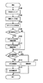
- FIG. 2 is a flowchart showing the procedure of the main process.
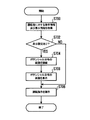
- FIG. 3 is a flowchart showing the procedure of the travel control process.
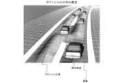
- FIG. 4A is a diagram showing the concept of potential distribution;
- FIG. 4B is a schematic diagram showing the density distribution of FIG. 4A with dots.
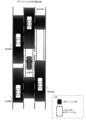
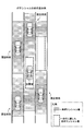
- FIG. 5A is a diagram illustrating a display example of a potential distribution,
- FIG. 5B is a schematic diagram showing the density distribution of FIG. 5A with dots.
- FIG. 1 is a block diagram showing a schematic configuration of the travel control system of the first embodiment.
- FIG. 2 is a flowchart showing the procedure of the main process.
- FIG. 3 is a flowchart showing the procedure of the travel control process.
- FIG. 4A is a diagram showing the concept of potential distribution
- FIG. 4B is a schematic diagram showing the density distribution of FIG. 4A with dots.
- FIG. 6 is a block diagram illustrating a schematic configuration of the server and the in-vehicle device according to the second embodiment.
- FIG. 7 is a flowchart showing a procedure of information transmission processing.
- FIG. 8 is a flowchart showing the procedure of the main process.
- FIG. 9 is a flowchart showing the procedure of the control determination process.
- FIG. 10 is a flowchart showing the procedure of the vehicle control process.
- FIG. 11 is a flowchart showing the procedure of the driving instruction process.
- the travel control system 1 of the first embodiment includes a detection unit 10, a vehicle information input unit 11, a positioning unit 12, a map information input unit 13, an operation unit 14, a communication unit 15, a display unit 16, and A control unit 17 and a storage unit 19 are provided.
- the detection unit 10 includes sensors for detecting the position, relative speed, and size of a surrounding vehicle that travels in the same direction as the host vehicle on the lane in which the host vehicle is traveling and on the adjacent lane.
- the detection unit 10 is embodied by, for example, a sonar, a radar, a camera, or the like.
- Sonar transmits ultrasonic waves from each antenna directed in the front / rear / left / right direction of the vehicle and receives the reflected waves. And based on the received reflected wave, about the object which exists in the front-back, left-right direction of the own vehicle, a positional relationship with the own vehicle, a distance, etc. are output.
- the radar scans a predetermined detection area by irradiating a laser or millimeter wave from an antenna directed in the front / rear / left / right direction of the host vehicle, and receives the reflected wave. And based on the received reflected wave, the positional relationship with the host vehicle, distance, relative speed, etc. are output about the object which exists in the front-back, left-right direction of a vehicle.
- the camera is provided at a predetermined position in the front / rear / left / right direction of the host vehicle, and outputs imaging data showing surrounding vehicles existing in the front / rear / left / right direction of the host vehicle.
- a plurality of sensors such as sonar, radar, and camera may be used in combination, or may be used alone.
- the vehicle information input unit 11 inputs information indicating the state of the host vehicle related to travel control to the control unit 17. Examples of information indicating the state of the host vehicle include speed, accelerator opening, brake operation amount, steering angle, and the like.
- the positioning unit 12 measures the current location of the host vehicle.
- the positioning unit 12 is embodied by, for example, a high-accuracy positioning receiver that supports high-precision GPS (Global Positioning System).
- the map information input unit 13 acquires information about a road on which the host vehicle is currently traveling from a storage medium that stores road map information, and inputs the information to the control unit 17. In the present embodiment, information such as the number of lanes, the lane width, the turn, the gradient, the merge, and the regulation is assumed as the road information input by the map information input unit 13.
- the operation unit 14 is an input device for inputting operation instructions such as on / off of travel control and on / off of display of a potential distribution image.
- a switch provided in a spoke portion of a steering wheel of a vehicle, etc. It is embodied by.
- the communication unit 15 is a communication device for performing road-to-vehicle communication and vehicle-to-vehicle communication with a roadside wireless communication station and a communication device mounted on a surrounding vehicle.
- the display unit 16 is a display device that includes a center display provided in the center of the instrument panel and an indicator provided in the meter panel. The center display displays an image of the potential distribution drawn by the control unit 17. Moreover, the indicator in a meter panel displays the on / off state of traveling control.
- the control unit 17 is an information processing apparatus mainly configured by a CPU, a ROM, a RAM, and the like (not shown), and comprehensively controls each unit of the traveling control system 1.
- the control unit 17 executes various processes when the CPU executes a control program stored in the ROM.
- the control unit 17 is connected to a vehicle control unit 18 to be controlled by a travel control process executed by the control unit 17.
- various electronic control devices such as an engine control ECU, a brake control ECU, and a steering angle ECU are assumed as the vehicle control unit 18.
- the engine control ECU controls the output of the engine by issuing a control command corresponding to the operation amount of the accelerator pedal and the state of the engine.
- the brake control ECU controls the braking force of the brake according to the operation amount of the brake pedal.
- the steering angle control ECU controls the steering angle of the steering.
- the controller 17 automatically controls the traveling state of the vehicle by giving commands to the engine control ECU, the brake control ECU, and the steering angle control ECU in a travel control process described later.
- the storage unit 19 is a storage device that stores learning information related to driving behavior of the host vehicle. Based on information input from the detection unit 10, the vehicle information input unit 11, the positioning unit 12, the map information input unit 13, and the like, the control unit 17 determines the distance between the host vehicle and the surrounding vehicle, and the host vehicle has traveled. Information representing driving behavior such as the position of the lane is stored in the storage unit 19 as learning information.
- the control unit 17 senses the vicinity of the host vehicle by the detection unit 10. Here, the position, size, relative speed, etc. of the vehicle existing around the host vehicle are detected. The detection of the surrounding vehicles is performed based on the image recognition of the image captured by the camera of the detection unit 10 and the measurement results of radar, sonar, and the like. Further, the lane in which the host vehicle is traveling is recognized by recognizing the white line from the image captured by the camera. In S102, the control unit 17 creates a bird's-eye view image representing the positional relationship between the own vehicle and the surrounding vehicle on the road based on the surrounding vehicle detected in S100, the position of the own vehicle, and the road map information.
- This bird's-eye view is a composition that looks down on the positional relationship between the host vehicle and the surrounding vehicles on the driving lane where the host vehicle is located or on the adjacent lane in the same direction, from the top of the host vehicle. It is arranged at a corresponding position in the region where the shape is reproduced.
- the control unit 17 assigns a potential field to each peripheral vehicle of the bird's-eye image created in S102, and combines the potential fields of each peripheral vehicle to express the potential field distribution state in the entire bird's-eye image region. Create a distribution.
- the potential field is a concept in which the degree of psychological pressure that the presence of surrounding vehicles has on the driver of the host vehicle is associated with the position on the road. In the present embodiment, the following method is exemplified as a specific potential field calculation method.
- the value of the potential field is added to the area from the front end or rear end of the surrounding vehicle to the predetermined safety distance.
- the width of the potential field applied in the longitudinal direction of the surrounding vehicle is the width of the lane where the surrounding vehicle is located.
- the value of the potential field is set to 0 at a position away from the safety distance in the front-rear direction.
- the value of the potential field in the region less than the safe distance may be set so as to increase as it approaches the surrounding vehicle, or may be set to a constant value regardless of the distance from the surrounding vehicle.
- This safety distance is, for example, 22 m when the speed of the host vehicle is 40 km / h, 44 m when the host vehicle is 60 km / h, 112 m when the host vehicle speed is 100 km / h, and so on. It is conceivable to make it variable according to (speed). Further, when it is raining (when the wiper is activated), the safety distance may be set to 1.5 times the normal distance. Or you may make it set the value of a potential field high, so that the speed of the own vehicle and the speed of a surrounding vehicle are high.
- the left-right area of the surrounding vehicle it is assumed that the area of one lane adjacent to the lane where the surrounding vehicle is located will be affected by this surrounding vehicle, and the length of the surrounding vehicle is equivalent to the width of the adjacent lane.
- the potential field value and range depending on the size of the surrounding vehicle. May be adjusted. For example, as the vehicle height detected by the detection unit 10 is higher, it is conceivable that the region to which the potential field is applied is expanded or the value of the potential field is increased. In addition, it is conceivable to increase the value of the potential field applied in the left-right direction of the surrounding vehicle as the vehicle width detected by the detection unit 10 increases.
- the value and range of the potential field applied to the surrounding vehicles may be adjusted according to the properties of the road such as the width, turn, and gradient of the road indicated by the road map information. Specifically, in places where the width of the road is below the standard, or places where there are bends or slopes above the standard, it may be possible to expand the range to which the potential field is applied or to increase the potential field value higher than usual. .
- the potential field can be broadened under bad weather conditions such as precipitation, strong wind, or fog, or the potential field value can be set higher than usual. You may comprise so that it may become high. Further, the configuration may be such that the user can arbitrarily change the width of the potential field and the reference of the value via the operation unit 14.
- the value and range of the potential field applied to the surrounding vehicle can be made variable based on the driving behavior tendency represented by the learning information accumulated in the storage unit 19. For example, if the driver tends to maintain a relatively short (or long) inter-vehicle distance based on learning information related to the inter-vehicle distance, the range of the potential field applied to the rear of the surrounding vehicle is set short (or long). Can be considered. Also, based on learning information about the position of the lane on which the host vehicle has traveled, the height of the potential field applied to the lane that the driver prefers to travel is set relatively low, and is applied to the lane where the driver does not travel much. It can be considered to set the height of the potential field relatively high.
- FIGS. 4A and 4B are abstract representations of the potential distribution created in S104.
- a potential field formed in a region adjacent to the surrounding vehicle in the front-rear and left-right directions is represented by a bump on the road surface.
- a high potential field expressed by road bumps it means that the degree of psychological pressure experienced by the driver of the vehicle is strong.
- the control unit 17 branches the process depending on whether or not the setting for displaying an image visualizing the potential distribution is turned on. In the present embodiment, it is assumed that the driver can designate on / off of the display at any time via the steering switch of the operation unit 14.
- the control unit 17 proceeds to S112.
- the control unit 17 proceeds to S108.
- the control unit 17 draws a virtual image for visualizing the potential distribution created in S104.
- a specific example of the potential distribution image drawn in S108 will be described with reference to FIGS. 5A and 5B.
- the image of the potential distribution is drawn with a composition overlooking the road around the host vehicle from above the host vehicle.
- an image of the detected surrounding vehicle is drawn in an area corresponding to the relative position with the host vehicle.
- a potential field is drawn around the image of each surrounding vehicle.
- the potential field is represented by the color depth of the image, and the region having a higher potential field value is drawn in a darker color.
- a region outside the range of the potential field formed by the surrounding vehicle is defined as a low potential field.
- a range in which the value of the potential field is equal to or less than the reference value may be included in the low potential field.
- FIGS. 5A and 5B when a low potential field that is wider than the entire length of the host vehicle exists in a range that can be moved from the position of the host vehicle, highlighting that is a broken-line rectangle is applied to the range of the potential field. ing. Thereby, a low potential field suitable for the host vehicle to travel is clearly indicated.
- 5A and 5B show an example in which the potential distribution is drawn as a two-dimensional bird's-eye view image. However, as illustrated in FIGS. 4A and 4B, the drawing is performed as a three-dimensional stereoscopic image. Also good.
- the control unit 17 displays the potential distribution image drawn in S108 on the center display of the display unit 16.
- the control unit 17 branches the process depending on whether or not the current situation of the host vehicle satisfies the travel control cancellation condition.
- the travel control release condition it is assumed that the driver can set the travel control on / off at any time via a steering switch of the operation unit 14 or the like.
- traffic congestion has occurred in front of the course of the host vehicle based on the traffic flow around the host vehicle detected by the detection unit 10 and traffic jam information received by the communication unit 15. It is assumed that the travel control is canceled on the condition that it has been determined. Thereafter, the travel control is resumed on the condition that information indicating that the traffic jam is resolved is acquired.
- the control unit 17 proceeds to S114.
- S ⁇ b> 114 the control unit 17 notifies the driver that the traveling control is performed via the display unit 16. Specifically, the indicator in the meter panel displays a state where the traveling control is on.
- the control unit 17 executes a travel control process based on the potential distribution created in S104. The detailed procedure of this traveling control process will be described later. After S118, the control unit 17 ends this process.
- control unit 17 proceeds to S116.
- the control part 17 notifies a driver
- the control unit 17 determines whether the potential at the position where the host vehicle is present is high in the potential distribution created in S104. When the position of the own vehicle corresponds to the low potential field (S200: NO), the control unit 17 proceeds to S202.
- the low potential field refers to a region outside the range of the potential field formed by the surrounding vehicle. Alternatively, a range in which the value of the potential field formed by the surrounding vehicles is equal to or less than the reference value may be included in the low potential field.
- the control unit 17 instructs the engine control ECU of the vehicle control unit 18 to maintain the current speed.
- the control part 17 progresses to S204.
- the high potential field here refers to the range of the potential field formed by the surrounding vehicles. Or you may exclude from the high potential field about the range whose potential value is below a reference value among the potential fields formed by surrounding vehicles.
- the control unit 17 retreats from the high potential field to the low potential field by changing the relative position of the host vehicle in the front-rear direction while maintaining the current travel lane in the potential distribution created in S104. Determine whether it is possible.
- there is a sufficiently low potential field in front of or behind the traveling lane where the host vehicle is located and no other vehicle exists on the traveling lane between the host vehicle and the low potential field. Affirmative determination is made on the condition.
- control unit 17 proceeds to S206.
- the control unit 17 instructs the engine control ECU and the brake control ECU of the vehicle control unit 18 to adjust the speed so that the host vehicle enters a low potential field in front of or behind the traveling lane.
- the driver may be notified in advance by voice or the like.
- the control unit 17 determines whether or not the vehicle can be evacuated to a low potential field by changing the lane to the adjacent lane adjacent to the traveling lane where the host vehicle is located.
- the control unit 17 determines whether or not the vehicle can be evacuated to a low potential field by changing the lane to the adjacent lane adjacent to the traveling lane where the host vehicle is located.
- one of the conditions for making an affirmative determination is that there is a sufficiently low potential field in a range that can be entered by changing the lane to the adjacent lane.
- overtaking with respect to surrounding vehicles traveling in adjacent lanes may be involved.
- control unit 17 proceeds to S210.
- the control unit 17 controls the engine control ECU, brake control ECU, and steering angle control ECU of the vehicle control unit 18 so that the host vehicle enters the low potential field in the adjacent lane by changing the lane or overtaking. Commanding and steering. When changing lanes or overtaking, the driver may be notified in advance by voice or the like.
- the control unit 17 ends the present process without performing the traveling control.
- the speed, size of surrounding vehicles, road properties, and weather conditions can be reflected in the potential field calculation.
- an optimum potential distribution according to the speed and the surrounding situation can be created, and more accurate traveling control is realized based on the optimum potential distribution.
- the image (see FIGS. 5A and 5B) in which the potential distribution is visualized can be displayed to the driver, the driver can determine where the driver can reduce the feeling of psychological pressure by the surrounding vehicle. It is convenient because it can be easily grasped.
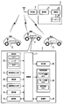
- the server-managed travel control system includes an in-vehicle device 2 mounted on each of a plurality of vehicles traveling on a road, and a server 3 installed in an information center that provides information to vehicles in a wide area. It consists of.
- the second embodiment is different from the first embodiment in that the server 3 executes the creation of potential distribution and the determination of vehicle control for a plurality of vehicles.
- the in-vehicle device 2 includes a detection unit 10, a vehicle information input unit 11, a positioning unit 12, a map information input unit 13, an operation unit 14, a communication unit 15, a display unit 16, as in the traveling control system 1 of the first embodiment. And a control unit 17, a vehicle control unit 18, a storage unit 19 and the like.
- symbol shall be used about the component similar to the traveling control system 1 of 1st Embodiment, and description about a common function is abbreviate
- the communication unit 15 of the in-vehicle device 2 performs wireless communication with the server 3 through the base station 4 of the wide area communication network.
- the server 3 is an information processing apparatus installed in an organization (information center) that provides various types of information to vehicles in a wide area.
- the server 3 communicates with the in-vehicle device 2 via a base station 4 and a wireless communication network provided in a wide area.
- the server 3 includes a communication unit 31, a calculation unit 32, a database 33, and the like for communicating with the outside via the base station 4.
- the server 3 collects various information uploaded from a large number of vehicles traveling on the road. Based on the information collected from each vehicle, the calculation unit 32 creates control information related to the travel control of each vehicle and distributes the control information to each vehicle. Further, the database 33 stores learning information related to driving behavior for each vehicle that has provided information to the server 3. Based on the information uploaded from each vehicle, the calculation unit 32 associates information representing the driving behavior of each vehicle such as the inter-vehicle distance and the position of the lane in which the vehicle is traveling with the identification information of each vehicle in the database 33 as learning information. accumulate.
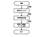
- the control unit 17 senses the periphery of the host vehicle by the detection unit 10. Here, the position, size, relative speed, etc. of the vehicle existing around the host vehicle are detected. The detection of the surrounding vehicles is performed based on the image recognition of the image captured by the camera of the detection unit 10 and the measurement results of radar, sonar, and the like. Further, the lane in which the host vehicle is traveling is recognized by recognizing the white line from the image captured by the camera. In S ⁇ b> 302, the control unit 17 acquires information representing the state of the host vehicle and the current location from the vehicle information input unit 11 and the positioning unit 12. Examples of information indicating the state of the host vehicle include speed, accelerator opening, brake operation amount, steering angle, and the like.
- control unit 17 transmits the information acquired in S300 and S302 to the server 3 in association with the identification information (vehicle ID) of the host vehicle.
- the information transmitted to the server 3 in S304 includes information indicating whether or not automatic driving control that automatically performs speed adjustment and steering is possible. After S304, the control unit 17 ends this process.
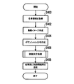
- the calculation unit 32 acquires information transmitted from a plurality of vehicles traveling on a predetermined road section. Moreover, the structure which acquires the information regarding the vehicle detected by the camera, sensor, etc. which were installed as the infrastructure in the said road area may be sufficient.
- the calculation unit 32 creates a bird's-eye image representing the positional relationship of each vehicle on the road based on the information received from each vehicle in S400 and the local road map information.
- This bird's-eye view is a composition in which the positional relationship of all vehicles traveling in the same direction on a given road section is viewed from above, and is arranged at the corresponding position in the area where the number of lanes and the shape of the road are reproduced. It is.
- positioned at a bird's-eye view image contains not only the vehicle which mounted the vehicle-mounted apparatus 2 and provided the information to the server 3, but the surrounding vehicle detected by the sensor of the vehicle mounted with the vehicle-mounted apparatus 2.
- the calculation unit 32 assigns a potential field to each surrounding vehicle of the bird's-eye image created in S402, and combines the potential fields of each vehicle to express the potential distribution representing the potential field distribution in the entire bird's-eye image region.
- Create The potential field is a concept in which the degree of psychological pressure that the presence of each vehicle exerts on the driver of other surrounding vehicles is associated with the position on the road. Note that a specific potential field calculation method is the same as that described for S104 (see FIG. 2) of the first embodiment, and therefore, a duplicate description is omitted.
- the calculation unit 32 executes a control determination process based on the potential distribution created in S404. The detailed procedure of this control determination process will be described later. And in S408, the calculating part 32 transmits the control information regarding the automatic driving
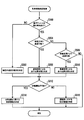
- the calculation unit 32 determines whether or not a vehicle is present at a position corresponding to the high potential field in the potential distribution created in S404.
- the high potential field here refers to the range of a potential field formed by other vehicles existing around a certain vehicle. Or you may exclude from the high potential field about the range whose potential value is below a reference value among potential fields formed by other vehicles.
- the calculation unit 32 proceeds to S502. In S502, the calculation unit 32 determines the control content for maintaining the current speed for each vehicle on which the in-vehicle device 2 is mounted.
- the arithmetic unit 32 proceeds to S504.
- the calculation unit 32 changes the relative position of the vehicle mounted with the in-vehicle device 2 in the front-rear direction among the corresponding vehicle in the high potential field and other vehicles in the vicinity thereof, It is determined whether or not the vehicle can evacuate from the high potential field.
- the arithmetic unit 32 proceeds to S506.
- the calculation unit 32 determines the content of control for changing the travel position by adjusting the speed of the specific vehicle that is the target of the specific travel control so that the vehicle leaves the high potential field.
- the arithmetic unit 32 proceeds to S508.
- the calculation unit 32 changes the lane of any vehicle in which the in-vehicle device 2 is mounted among the corresponding vehicles in the high potential field or other vehicles in the vicinity thereof, so that the corresponding vehicle is withdrawn from the high potential field. Determine whether it is possible.
- one of the conditions for making an affirmative determination is that there is a sufficiently low potential field in a range that can be entered by changing the lane to the adjacent lane.
- overtaking with respect to surrounding vehicles traveling in adjacent lanes may be involved.
- the calculation unit 32 proceeds to S510.
- the calculation part 32 determines the control content which changes the lane of the specific vehicle used as driving
- the calculation unit 32 ends this process.
- the calculation unit 32 branches the process depending on whether or not the specific vehicle that is the target of the control content determined in S502, S506, and S510 is capable of automatic driving.
- the calculation unit 32 proceeds to S514.
- the calculation unit 32 creates control information related to speed adjustment and steering necessary to achieve the traveling state according to the determined control content by the automatic traveling control. After S514, the calculation unit 32 ends this process.
- the calculation unit 32 proceeds to S516.
- the calculation unit 32 creates instruction information to be presented to the driver in order to cause the driver to execute the traveling state according to the determined control content. After S516, the calculation unit 32 ends this process.
- the control content for the vehicle when determining the control content for the vehicle in the above-described S506 and S510, it may be configured to reflect the tendency of the driving behavior represented by the learning information accumulated in the database 33. For example, if the driver has a tendency to maintain a relatively short (or long) inter-vehicle distance based on learning information related to the inter-vehicle distance of a vehicle subject to speed adjustment, the inter-vehicle distance is made relatively short (or It is conceivable to determine the control contents so as to take longer. Further, it is conceivable to determine the control content related to the lane change so that the driver can preferentially travel the lane that the driver likes to travel based on the learning information regarding the position of the lane on which the host vehicle has traveled.
- control unit 17 acquires control information related to automatic driving and image information related to the potential field from the server 3. These pieces of information are information transmitted in S408 of the main process (see FIG. 8) executed by the server 3.
- the control unit 17 branches the process depending on whether or not the setting for displaying an image visualizing the potential distribution is turned on. In the present embodiment, it is assumed that the driver can designate on / off of the display at any time via the steering switch of the operation unit 14.
- the control unit 17 proceeds to S608.
- the control unit 17 proceeds to S604.
- control unit 17 draws an image for displaying the potential distribution on the center display of the display unit 16 according to the image information acquired in S600.
- a specific example of an image in which the potential distribution is visualized is as described in the display examples of FIGS. 5A and 5B in the first embodiment.
- control unit 17 displays the potential distribution image drawn in step S604 on the center display of the display unit 16.
- the control unit 17 notifies the driver by voice or the like that the running state is controlled by automatic driving.
- the control unit 17 executes traveling control by automatic driving. Specifically, the control unit 17 instructs the engine control ECU, brake control ECU, and steering angle control ECU of the vehicle control unit 18 to adjust the speed and steer according to the control information acquired in S600.
- the control unit 17 instructs the engine control ECU, brake control ECU, and steering angle control ECU of the vehicle control unit 18 to adjust the speed and steer according to the control information acquired in S600.
- it is only control of the inter-vehicle distance by speed adjustment after performing the travel control after notifying the driver of the content of the travel control, if the travel control accompanied by the lane change, after notifying the content of the travel control, You may make it implement driving
- the control unit 17 ends this process.
- control unit 17 acquires instruction information for the driver and image information related to the potential field from the server 3. These pieces of information are information transmitted in S408 of the main process (see FIG. 8) executed by the server 3.
- the control unit 17 branches the process depending on whether or not the setting for displaying an image visualizing the potential distribution is turned on. In the present embodiment, it is assumed that the driver can designate on / off of the display at any time via the steering switch of the operation unit 14.
- the control unit 17 proceeds to S708.
- the control unit 17 proceeds to S704.
- control unit 17 draws an image for displaying the potential distribution on the center display of the display unit 16 according to the image information acquired in S700.
- a specific example of an image in which the potential distribution is visualized is as described in the display examples of FIGS. 5A and 5B in the first embodiment.
- control unit 17 displays the image of the potential distribution drawn in step S704 on the center display of the display unit 16.
- control part 17 shows the driving
- the server 3 can collect information on a plurality of vehicles traveling on the road and generate a potential field distribution for each vehicle. Based on the distribution of the generated potential field, information for controlling the traveling state of each vehicle can be comprehensively determined so that each vehicle travels while avoiding the high potential field. Then, the control information determined by the server 3 is notified to each vehicle, and the driving state is controlled in the in-vehicle device 2 of each vehicle based on the notified control information, so that the driver of each vehicle can see the surrounding vehicle. You can reduce the feeling of psychological pressure from you.
- control information for controlling the running state by automatic driving is notified to the vehicle, and for vehicles that do not perform automatic driving, instruction information for the driver is transmitted to the vehicle. Can be notified. In this way, it is possible to comprehensively control the running state of each vehicle so that each vehicle can run avoiding a position with a high potential field on a road where vehicles that perform automatic driving and vehicles that do not perform automatic driving are mixed. .
- each section is expressed as S100, for example.
- each section can be divided into a plurality of subsections, while a plurality of sections can be combined into one section.
- each section configured in this manner can be referred to as a device, module, or means.
Priority Applications (3)
| Application Number | Priority Date | Filing Date | Title |
|---|---|---|---|
| US15/032,513 US9643603B2 (en) | 2013-10-30 | 2014-10-16 | Travel controller, server, and in-vehicle device |
| DE112014005021.0T DE112014005021B4 (de) | 2013-10-30 | 2014-10-16 | Fahrtsteuervorrichtung, Server und In-Vehicle-Vorrichtung |
| CN201480059839.0A CN105745131B (zh) | 2013-10-30 | 2014-10-16 | 行驶控制装置、服务器、车载装置 |
Applications Claiming Priority (4)
| Application Number | Priority Date | Filing Date | Title |
|---|---|---|---|
| JP2013225526 | 2013-10-30 | ||
| JP2013-225526 | 2013-10-30 | ||
| JP2014170669A JP6441610B2 (ja) | 2013-10-30 | 2014-08-25 | 走行制御装置及びサーバ |
| JP2014-170669 | 2014-08-25 |
Publications (1)
| Publication Number | Publication Date |
|---|---|
| WO2015064041A1 true WO2015064041A1 (ja) | 2015-05-07 |
Family
ID=53003675
Family Applications (1)
| Application Number | Title | Priority Date | Filing Date |
|---|---|---|---|
| PCT/JP2014/005268 WO2015064041A1 (ja) | 2013-10-30 | 2014-10-16 | 走行制御装置、サーバ、車載装置 |
Country Status (5)
| Country | Link |
|---|---|
| US (1) | US9643603B2 (de) |
| JP (1) | JP6441610B2 (de) |
| CN (1) | CN105745131B (de) |
| DE (1) | DE112014005021B4 (de) |
| WO (1) | WO2015064041A1 (de) |
Cited By (8)
| Publication number | Priority date | Publication date | Assignee | Title |
|---|---|---|---|---|
| JP2015110403A (ja) * | 2013-10-30 | 2015-06-18 | 株式会社デンソー | 走行制御装置、サーバ、車載装置 |
| WO2016199285A1 (ja) * | 2015-06-12 | 2016-12-15 | 三菱電機株式会社 | 運転支援装置および運転支援方法 |
| JPWO2018020604A1 (ja) * | 2016-07-27 | 2018-07-26 | みこらった株式会社 | 車載装置、自動車、情報提供システム、車載装置用プログラム及び自動車用プログラム |
| RU2682685C1 (ru) * | 2015-07-28 | 2019-03-20 | Ниссан Мотор Ко., Лтд. | Способ и устройство управления движением |
| DE102017009609A1 (de) | 2017-10-17 | 2019-04-18 | Daimler Ag | Verfahren zur Ausgabe einer Überholempfehlung |
| CN110290985A (zh) * | 2017-01-30 | 2019-09-27 | 捷豹路虎有限公司 | 控制车辆的运动 |
| JP2019185246A (ja) * | 2018-04-05 | 2019-10-24 | 三菱電機株式会社 | 自動運転制御システム |
| US20210253107A1 (en) * | 2018-06-29 | 2021-08-19 | Nissan Motor Co., Ltd. | Drive Assisting Method and Vehicle Control Device |
Families Citing this family (46)
| Publication number | Priority date | Publication date | Assignee | Title |
|---|---|---|---|---|
| DE102014212478A1 (de) * | 2014-06-27 | 2015-12-31 | Bayerische Motoren Werke Aktiengesellschaft | Verfahren zur Erstellung eines Umfeldmodells eines Fahrzeugs |
| JP2016103194A (ja) * | 2014-11-28 | 2016-06-02 | パナソニックIpマネジメント株式会社 | 車両走行支援装置及び車両走行支援方法 |
| DE102015204282A1 (de) * | 2015-03-10 | 2016-09-15 | Robert Bosch Gmbh | Verfahren zum Betreiben eines Kraftfahrzeuges, Steuervorrichtung und Computerprogrammprodukt |
| BR112018001589A2 (pt) * | 2015-07-28 | 2018-09-18 | Nissan Motor Co., Ltd. | método de controle de viagem e aparelho de controle de viagem |
| RU2695010C1 (ru) * | 2015-07-28 | 2019-07-18 | Ниссан Мотор Ко., Лтд. | Способ управления движением и устройство управления движением |
| JP6451852B2 (ja) * | 2015-07-28 | 2019-01-16 | 日産自動車株式会社 | 走行制御装置の制御方法および走行制御装置 |
| EP3330946A4 (de) * | 2015-07-31 | 2019-07-03 | Hitachi Automotive Systems, Ltd. | Fahrzeugperipherieinformationverwaltungsvorrichtung |
| JP2017114155A (ja) * | 2015-12-21 | 2017-06-29 | 三菱自動車工業株式会社 | 運転支援装置 |
| JP2017136968A (ja) * | 2016-02-04 | 2017-08-10 | 日立オートモティブシステムズ株式会社 | 車両制御装置 |
| JP6962397B2 (ja) * | 2016-03-15 | 2021-11-05 | 株式会社デンソー | 表示制御装置及び表示制御方法 |
| JP6665605B2 (ja) * | 2016-03-15 | 2020-03-13 | 株式会社デンソー | 表示制御装置及び表示制御方法 |
| JP6558738B2 (ja) * | 2016-03-16 | 2019-08-14 | パナソニックIpマネジメント株式会社 | 運転支援装置、運転支援システム、運転支援方法、運転支援プログラム及び自動運転車両 |
| DE102016115071A1 (de) * | 2016-08-15 | 2018-02-15 | Valeo Schalter Und Sensoren Gmbh | Verfahren und Vorrichtung zum Regeln einer Geschwindigkeit und/oder Beschleunigung eines Kraftfahrzeugs, Fahrerassistenzsystem sowie Kraftfahrzeug |
| JP6776058B2 (ja) * | 2016-08-26 | 2020-10-28 | シャープ株式会社 | 自律走行車両制御装置、自律走行車両制御システム及び自律走行車両制御方法 |
| JP6610798B2 (ja) * | 2016-09-09 | 2019-11-27 | 日産自動車株式会社 | 車両の走行制御方法および走行制御装置 |
| JP6473727B2 (ja) * | 2016-09-09 | 2019-02-20 | 本田技研工業株式会社 | 走行制御装置 |
| KR102057532B1 (ko) | 2016-10-12 | 2019-12-20 | 한국전자통신연구원 | 자율주행 차량의 판단 지능 향상을 위한 주행상황 데이터 공유 및 학습 장치 및 그 동작 방법 |
| WO2018074541A1 (ja) * | 2016-10-21 | 2018-04-26 | マツダ株式会社 | 車両制御装置 |
| CN106856502A (zh) * | 2016-12-02 | 2017-06-16 | 北京京东尚科信息技术有限公司 | 无人车控制方法、无人车、服务器和无人车系统 |
| US11180141B2 (en) * | 2016-12-05 | 2021-11-23 | Mazda Motor Corporation | Vehicle control system |
| JP6447963B2 (ja) * | 2016-12-05 | 2019-01-09 | マツダ株式会社 | 車両制御装置 |
| JP6447962B2 (ja) * | 2016-12-05 | 2019-01-09 | マツダ株式会社 | 車両制御装置 |
| JP6686871B2 (ja) * | 2016-12-26 | 2020-04-22 | トヨタ自動車株式会社 | 自動運転システム |
| CN110121449B (zh) * | 2017-01-11 | 2022-06-28 | 本田技研工业株式会社 | 车辆控制装置、车辆控制方法及存储介质 |
| JP6734205B2 (ja) * | 2017-01-13 | 2020-08-05 | トヨタ自動車株式会社 | 疲労度推定装置 |
| JP6796798B2 (ja) * | 2017-01-23 | 2020-12-09 | パナソニックIpマネジメント株式会社 | イベント予測システム、イベント予測方法、プログラム、及び移動体 |
| CN106897855B (zh) * | 2017-03-10 | 2020-09-08 | 深圳市赛亿科技开发有限公司 | 一种智能无人配送车和无人配送系统 |
| WO2019003325A1 (ja) * | 2017-06-28 | 2019-01-03 | 三菱電機株式会社 | 走行計画修正装置および走行計画修正方法 |
| JP6768604B2 (ja) * | 2017-07-03 | 2020-10-14 | 日立オートモティブシステムズ株式会社 | 車両制御装置 |
| JP6651486B2 (ja) * | 2017-09-01 | 2020-02-19 | 本田技研工業株式会社 | 車両制御装置、車両制御方法、およびプログラム |
| JP6600878B2 (ja) * | 2017-12-21 | 2019-11-06 | 本田技研工業株式会社 | 車両制御装置、車両制御方法、およびプログラム |
| KR102018554B1 (ko) * | 2018-01-18 | 2019-09-05 | 엘지전자 주식회사 | 차량에 구비된 차량 제어 장치 및 차량의 제어방법 |
| GB2570887B (en) * | 2018-02-07 | 2020-08-12 | Jaguar Land Rover Ltd | A system for a vehicle |
| EP3533656A1 (de) * | 2018-03-02 | 2019-09-04 | Panasonic Intellectual Property Corporation of America | Vorrichtung und programm zur verarbeitung von fahrzeugreiseinformationen und zur vermeidung von kollisionen |
| US20190300017A1 (en) * | 2018-04-02 | 2019-10-03 | GM Global Technology Operations LLC | Method of controlling a vehicle |
| US10349246B1 (en) * | 2018-05-08 | 2019-07-09 | BaiJie Teng Technology Corporation | Method and system for vehicle-to-vehicle identification and detection |
| DE102018122374A1 (de) * | 2018-09-13 | 2020-03-19 | Valeo Schalter Und Sensoren Gmbh | Verfahren zum Bestimmen eines ein Kraftfahrzeug umgebenden Freiraums, Computerprogrammprodukt, Freiraumbestimmungseinrichtung und Kraftfahrzeug |
| JP7159849B2 (ja) * | 2018-12-21 | 2022-10-25 | トヨタ自動車株式会社 | 車両制御装置、車両制御方法、プログラム |
| US11410545B2 (en) * | 2019-07-19 | 2022-08-09 | Ford Global Technologies, Llc | Dynamic vehicle perimeter definition and reporting |
| EP3819665B1 (de) | 2019-11-06 | 2022-01-19 | Yandex Self Driving Group LLC | Verfahren und rechnervorrichtung zur kalibrierung eines lidar-systems |
| US11527073B2 (en) * | 2019-11-15 | 2022-12-13 | Honda Motor Co., Ltd. | System and method for providing an interpretable and unified representation for trajectory prediction |
| DE102019219577A1 (de) * | 2019-12-13 | 2021-06-17 | Continental Teves Ag & Co. Ohg | Verfahren und Vorrichtung zur Ermittlung einer durch ein Fahrzeug fahrbaren Trajektorie |
| CN115298073B (zh) | 2020-03-19 | 2024-01-02 | 日产自动车株式会社 | 车辆的行驶辅助方法及行驶辅助装置 |
| JP7061148B2 (ja) * | 2020-03-31 | 2022-04-27 | 本田技研工業株式会社 | 車両制御装置、車両制御方法、およびプログラム |
| JP7211397B2 (ja) * | 2020-05-15 | 2023-01-24 | トヨタ自動車株式会社 | 他車両表示システム |
| US11679768B2 (en) * | 2020-10-19 | 2023-06-20 | Toyota Motor Engineering & Manufacturing North America, Inc. | Systems and methods for vehicle lane estimation |
Citations (5)
| Publication number | Priority date | Publication date | Assignee | Title |
|---|---|---|---|---|
| JP2004258889A (ja) * | 2003-02-25 | 2004-09-16 | Toshiba Corp | 交通流シミュレーションシステム、方法、及びプログラム |
| JP2007287168A (ja) * | 2007-06-11 | 2007-11-01 | Toshiba Corp | 交通流シミュレーション方法 |
| JP2008282275A (ja) * | 2007-05-11 | 2008-11-20 | Toyota Motor Corp | 運転支援システム及び運転支援装置 |
| JP2010175314A (ja) * | 2009-01-28 | 2010-08-12 | Aisin Aw Co Ltd | 車載用ナビゲーション装置 |
| JP2012104031A (ja) * | 2010-11-12 | 2012-05-31 | Denso Corp | 走行支援装置 |
Family Cites Families (11)
| Publication number | Priority date | Publication date | Assignee | Title |
|---|---|---|---|---|
| JPH10211886A (ja) * | 1997-01-29 | 1998-08-11 | Honda Motor Co Ltd | 車両の操舵装置 |
| JP4173292B2 (ja) * | 2001-08-23 | 2008-10-29 | 日産自動車株式会社 | 車両用運転操作補助装置 |
| DE10254402B4 (de) | 2002-11-21 | 2011-02-17 | Lucas Automotive Gmbh | System zur Beeinflussung der Geschwindigkeit eines Kraftfahrzeuges |
| JP4496760B2 (ja) * | 2003-10-29 | 2010-07-07 | 日産自動車株式会社 | 車線逸脱防止装置 |
| JP4329622B2 (ja) * | 2004-06-02 | 2009-09-09 | 日産自動車株式会社 | 車両用運転操作補助装置および車両用運転操作補助装置を備えた車両 |
| JP4400584B2 (ja) * | 2006-03-01 | 2010-01-20 | トヨタ自動車株式会社 | 障害物検出方法及び障害物検出装置 |
| JP4254844B2 (ja) * | 2006-11-01 | 2009-04-15 | トヨタ自動車株式会社 | 走行制御計画評価装置 |
| DE102006061390B4 (de) | 2006-12-23 | 2019-05-16 | Volkswagen Ag | Umfelderfassungssystem und Umfelderfassungsverfahren eines Kraftfahrzeugs |
| JP5035303B2 (ja) * | 2009-06-17 | 2012-09-26 | トヨタ自動車株式会社 | 移動体、これを含むシステム、移動体の動作方法、及びプログラム |
| KR101102144B1 (ko) * | 2009-11-17 | 2012-01-02 | 주식회사 만도 | 차선 유지 제어 방법 및 시스템 |
| JP6441610B2 (ja) * | 2013-10-30 | 2018-12-19 | 株式会社デンソー | 走行制御装置及びサーバ |
-
2014
- 2014-08-25 JP JP2014170669A patent/JP6441610B2/ja not_active Expired - Fee Related
- 2014-10-16 DE DE112014005021.0T patent/DE112014005021B4/de not_active Expired - Fee Related
- 2014-10-16 CN CN201480059839.0A patent/CN105745131B/zh not_active Expired - Fee Related
- 2014-10-16 WO PCT/JP2014/005268 patent/WO2015064041A1/ja active Application Filing
- 2014-10-16 US US15/032,513 patent/US9643603B2/en active Active
Patent Citations (5)
| Publication number | Priority date | Publication date | Assignee | Title |
|---|---|---|---|---|
| JP2004258889A (ja) * | 2003-02-25 | 2004-09-16 | Toshiba Corp | 交通流シミュレーションシステム、方法、及びプログラム |
| JP2008282275A (ja) * | 2007-05-11 | 2008-11-20 | Toyota Motor Corp | 運転支援システム及び運転支援装置 |
| JP2007287168A (ja) * | 2007-06-11 | 2007-11-01 | Toshiba Corp | 交通流シミュレーション方法 |
| JP2010175314A (ja) * | 2009-01-28 | 2010-08-12 | Aisin Aw Co Ltd | 車載用ナビゲーション装置 |
| JP2012104031A (ja) * | 2010-11-12 | 2012-05-31 | Denso Corp | 走行支援装置 |
Cited By (12)
| Publication number | Priority date | Publication date | Assignee | Title |
|---|---|---|---|---|
| JP2015110403A (ja) * | 2013-10-30 | 2015-06-18 | 株式会社デンソー | 走行制御装置、サーバ、車載装置 |
| WO2016199285A1 (ja) * | 2015-06-12 | 2016-12-15 | 三菱電機株式会社 | 運転支援装置および運転支援方法 |
| JPWO2016199285A1 (ja) * | 2015-06-12 | 2017-10-19 | 三菱電機株式会社 | 運転支援装置および運転支援方法 |
| CN107615348A (zh) * | 2015-06-12 | 2018-01-19 | 三菱电机株式会社 | 驾驶辅助装置及驾驶辅助方法 |
| RU2682685C1 (ru) * | 2015-07-28 | 2019-03-20 | Ниссан Мотор Ко., Лтд. | Способ и устройство управления движением |
| JPWO2018020604A1 (ja) * | 2016-07-27 | 2018-07-26 | みこらった株式会社 | 車載装置、自動車、情報提供システム、車載装置用プログラム及び自動車用プログラム |
| CN110290985A (zh) * | 2017-01-30 | 2019-09-27 | 捷豹路虎有限公司 | 控制车辆的运动 |
| US11415979B2 (en) | 2017-01-30 | 2022-08-16 | Jaguar Land Rover Limited | Controlling movement of a vehicle |
| DE102017009609A1 (de) | 2017-10-17 | 2019-04-18 | Daimler Ag | Verfahren zur Ausgabe einer Überholempfehlung |
| JP2019185246A (ja) * | 2018-04-05 | 2019-10-24 | 三菱電機株式会社 | 自動運転制御システム |
| US20210253107A1 (en) * | 2018-06-29 | 2021-08-19 | Nissan Motor Co., Ltd. | Drive Assisting Method and Vehicle Control Device |
| US11447135B2 (en) * | 2018-06-29 | 2022-09-20 | Nissan Motor Co., Ltd. | Drive assisting method and vehicle control device |
Also Published As
| Publication number | Publication date |
|---|---|
| DE112014005021T5 (de) | 2016-08-11 |
| JP6441610B2 (ja) | 2018-12-19 |
| CN105745131B (zh) | 2018-02-13 |
| US9643603B2 (en) | 2017-05-09 |
| JP2015110403A (ja) | 2015-06-18 |
| CN105745131A (zh) | 2016-07-06 |
| DE112014005021B4 (de) | 2022-03-31 |
| US20160272199A1 (en) | 2016-09-22 |
Similar Documents
| Publication | Publication Date | Title |
|---|---|---|
| JP6441610B2 (ja) | 走行制御装置及びサーバ | |
| JP6477927B2 (ja) | 走行制御装置、及びサーバ | |
| US11703876B2 (en) | Autonomous driving system | |
| CN107783535B (zh) | 车辆控制装置 | |
| US10293748B2 (en) | Information presentation system | |
| JP6369488B2 (ja) | 車両制御装置 | |
| CN110895417B (zh) | 车辆控制装置、车辆控制方法及存储介质 | |
| JP6414567B2 (ja) | 車両用制限速度表示装置 | |
| JP7048398B2 (ja) | 車両制御装置、車両制御方法、およびプログラム | |
| CN108282512B (zh) | 用于使用车辆通信进行车辆控制的系统和方法 | |
| EP3048022A1 (de) | Kollisionsvermeidungs-regelungssystem und steuerungsverfahren | |
| US10795374B2 (en) | Vehicle control device | |
| US10173680B2 (en) | Vehicle speed control device | |
| US20160063858A1 (en) | Method and system for using global scene context for adaptive prediction and corresponding program, and vehicle equipped with such system | |
| CN108275149B (zh) | 使用车辆通信进行合并辅助的系统和方法 | |
| CN108263360B (zh) | 紧随场景下用于车辆控制的系统和方法 | |
| CN110087959B (zh) | 车辆控制系统、车辆控制方法及存储介质 | |
| JP2010072973A (ja) | 走行環境認識装置 | |
| CN108275152B (zh) | 车辆系统、控制车辆系统的计算机实施的方法和存储介质 | |
| WO2022044768A1 (ja) | 車両用表示装置 | |
| US11701967B2 (en) | Display control device, display control method, and storage medium | |
| JP2007145095A (ja) | 走行制御装置、走行制御方法、走行制御プログラムおよび記録媒体 | |
| CN110888432B (zh) | 显示系统、显示控制方法及存储介质 | |
| JP2004106588A (ja) | 車両用運転支援装置 | |
| CN110888431B (zh) | 通知系统、通知控制方法及存储介质 |
Legal Events
| Date | Code | Title | Description |
|---|---|---|---|
| 121 | Ep: the epo has been informed by wipo that ep was designated in this application |
Ref document number: 14858431 Country of ref document: EP Kind code of ref document: A1 |
|
| WWE | Wipo information: entry into national phase |
Ref document number: 15032513 Country of ref document: US |
|
| WWE | Wipo information: entry into national phase |
Ref document number: 112014005021 Country of ref document: DE Ref document number: 1120140050210 Country of ref document: DE |
|
| 122 | Ep: pct application non-entry in european phase |
Ref document number: 14858431 Country of ref document: EP Kind code of ref document: A1 |