WO2015063857A1 - 熱交換器、及び、空気調和装置 - Google Patents
熱交換器、及び、空気調和装置 Download PDFInfo
- Publication number
- WO2015063857A1 WO2015063857A1 PCT/JP2013/079247 JP2013079247W WO2015063857A1 WO 2015063857 A1 WO2015063857 A1 WO 2015063857A1 JP 2013079247 W JP2013079247 W JP 2013079247W WO 2015063857 A1 WO2015063857 A1 WO 2015063857A1
- Authority
- WO
- WIPO (PCT)
- Prior art keywords
- heat exchanger
- header
- refrigerant
- heat exchange
- flow path
- Prior art date
Links
Images


Classifications
-
- F—MECHANICAL ENGINEERING; LIGHTING; HEATING; WEAPONS; BLASTING
- F28—HEAT EXCHANGE IN GENERAL
- F28F—DETAILS OF HEAT-EXCHANGE AND HEAT-TRANSFER APPARATUS, OF GENERAL APPLICATION
- F28F9/00—Casings; Header boxes; Auxiliary supports for elements; Auxiliary members within casings
- F28F9/02—Header boxes; End plates
- F28F9/026—Header boxes; End plates with static flow control means, e.g. with means for uniformly distributing heat exchange media into conduits
-
- F—MECHANICAL ENGINEERING; LIGHTING; HEATING; WEAPONS; BLASTING
- F25—REFRIGERATION OR COOLING; COMBINED HEATING AND REFRIGERATION SYSTEMS; HEAT PUMP SYSTEMS; MANUFACTURE OR STORAGE OF ICE; LIQUEFACTION SOLIDIFICATION OF GASES
- F25B—REFRIGERATION MACHINES, PLANTS OR SYSTEMS; COMBINED HEATING AND REFRIGERATION SYSTEMS; HEAT PUMP SYSTEMS
- F25B39/00—Evaporators; Condensers
-
- F—MECHANICAL ENGINEERING; LIGHTING; HEATING; WEAPONS; BLASTING
- F28—HEAT EXCHANGE IN GENERAL
- F28D—HEAT-EXCHANGE APPARATUS, NOT PROVIDED FOR IN ANOTHER SUBCLASS, IN WHICH THE HEAT-EXCHANGE MEDIA DO NOT COME INTO DIRECT CONTACT
- F28D1/00—Heat-exchange apparatus having stationary conduit assemblies for one heat-exchange medium only, the media being in contact with different sides of the conduit wall, in which the other heat-exchange medium is a large body of fluid, e.g. domestic or motor car radiators
- F28D1/02—Heat-exchange apparatus having stationary conduit assemblies for one heat-exchange medium only, the media being in contact with different sides of the conduit wall, in which the other heat-exchange medium is a large body of fluid, e.g. domestic or motor car radiators with heat-exchange conduits immersed in the body of fluid
- F28D1/0233—Heat-exchange apparatus having stationary conduit assemblies for one heat-exchange medium only, the media being in contact with different sides of the conduit wall, in which the other heat-exchange medium is a large body of fluid, e.g. domestic or motor car radiators with heat-exchange conduits immersed in the body of fluid with air flow channels
- F28D1/024—Heat-exchange apparatus having stationary conduit assemblies for one heat-exchange medium only, the media being in contact with different sides of the conduit wall, in which the other heat-exchange medium is a large body of fluid, e.g. domestic or motor car radiators with heat-exchange conduits immersed in the body of fluid with air flow channels with an air driving element
-
- F—MECHANICAL ENGINEERING; LIGHTING; HEATING; WEAPONS; BLASTING
- F28—HEAT EXCHANGE IN GENERAL
- F28D—HEAT-EXCHANGE APPARATUS, NOT PROVIDED FOR IN ANOTHER SUBCLASS, IN WHICH THE HEAT-EXCHANGE MEDIA DO NOT COME INTO DIRECT CONTACT
- F28D1/00—Heat-exchange apparatus having stationary conduit assemblies for one heat-exchange medium only, the media being in contact with different sides of the conduit wall, in which the other heat-exchange medium is a large body of fluid, e.g. domestic or motor car radiators
- F28D1/02—Heat-exchange apparatus having stationary conduit assemblies for one heat-exchange medium only, the media being in contact with different sides of the conduit wall, in which the other heat-exchange medium is a large body of fluid, e.g. domestic or motor car radiators with heat-exchange conduits immersed in the body of fluid
- F28D1/04—Heat-exchange apparatus having stationary conduit assemblies for one heat-exchange medium only, the media being in contact with different sides of the conduit wall, in which the other heat-exchange medium is a large body of fluid, e.g. domestic or motor car radiators with heat-exchange conduits immersed in the body of fluid with tubular conduits
- F28D1/0408—Multi-circuit heat exchangers, e.g. integrating different heat exchange sections in the same unit or heat exchangers for more than two fluids
- F28D1/0426—Multi-circuit heat exchangers, e.g. integrating different heat exchange sections in the same unit or heat exchangers for more than two fluids with units having particular arrangement relative to the large body of fluid, e.g. with interleaved units or with adjacent heat exchange units in common air flow or with units extending at an angle to each other or with units arranged around a central element
-
- F—MECHANICAL ENGINEERING; LIGHTING; HEATING; WEAPONS; BLASTING
- F28—HEAT EXCHANGE IN GENERAL
- F28D—HEAT-EXCHANGE APPARATUS, NOT PROVIDED FOR IN ANOTHER SUBCLASS, IN WHICH THE HEAT-EXCHANGE MEDIA DO NOT COME INTO DIRECT CONTACT
- F28D1/00—Heat-exchange apparatus having stationary conduit assemblies for one heat-exchange medium only, the media being in contact with different sides of the conduit wall, in which the other heat-exchange medium is a large body of fluid, e.g. domestic or motor car radiators
- F28D1/02—Heat-exchange apparatus having stationary conduit assemblies for one heat-exchange medium only, the media being in contact with different sides of the conduit wall, in which the other heat-exchange medium is a large body of fluid, e.g. domestic or motor car radiators with heat-exchange conduits immersed in the body of fluid
- F28D1/04—Heat-exchange apparatus having stationary conduit assemblies for one heat-exchange medium only, the media being in contact with different sides of the conduit wall, in which the other heat-exchange medium is a large body of fluid, e.g. domestic or motor car radiators with heat-exchange conduits immersed in the body of fluid with tubular conduits
- F28D1/047—Heat-exchange apparatus having stationary conduit assemblies for one heat-exchange medium only, the media being in contact with different sides of the conduit wall, in which the other heat-exchange medium is a large body of fluid, e.g. domestic or motor car radiators with heat-exchange conduits immersed in the body of fluid with tubular conduits the conduits being bent, e.g. in a serpentine or zig-zag
- F28D1/0475—Heat-exchange apparatus having stationary conduit assemblies for one heat-exchange medium only, the media being in contact with different sides of the conduit wall, in which the other heat-exchange medium is a large body of fluid, e.g. domestic or motor car radiators with heat-exchange conduits immersed in the body of fluid with tubular conduits the conduits being bent, e.g. in a serpentine or zig-zag the conduits having a single U-bend
- F28D1/0476—Heat-exchange apparatus having stationary conduit assemblies for one heat-exchange medium only, the media being in contact with different sides of the conduit wall, in which the other heat-exchange medium is a large body of fluid, e.g. domestic or motor car radiators with heat-exchange conduits immersed in the body of fluid with tubular conduits the conduits being bent, e.g. in a serpentine or zig-zag the conduits having a single U-bend the conduits having a non-circular cross-section
-
- F—MECHANICAL ENGINEERING; LIGHTING; HEATING; WEAPONS; BLASTING
- F28—HEAT EXCHANGE IN GENERAL
- F28F—DETAILS OF HEAT-EXCHANGE AND HEAT-TRANSFER APPARATUS, OF GENERAL APPLICATION
- F28F1/00—Tubular elements; Assemblies of tubular elements
- F28F1/02—Tubular elements of cross-section which is non-circular
- F28F1/025—Tubular elements of cross-section which is non-circular with variable shape, e.g. with modified tube ends, with different geometrical features
-
- F—MECHANICAL ENGINEERING; LIGHTING; HEATING; WEAPONS; BLASTING
- F28—HEAT EXCHANGE IN GENERAL
- F28F—DETAILS OF HEAT-EXCHANGE AND HEAT-TRANSFER APPARATUS, OF GENERAL APPLICATION
- F28F9/00—Casings; Header boxes; Auxiliary supports for elements; Auxiliary members within casings
- F28F9/02—Header boxes; End plates
- F28F9/0219—Arrangements for sealing end plates into casing or header box; Header box sub-elements
- F28F9/0221—Header boxes or end plates formed by stacked elements
-
- F—MECHANICAL ENGINEERING; LIGHTING; HEATING; WEAPONS; BLASTING
- F28—HEAT EXCHANGE IN GENERAL
- F28F—DETAILS OF HEAT-EXCHANGE AND HEAT-TRANSFER APPARATUS, OF GENERAL APPLICATION
- F28F9/00—Casings; Header boxes; Auxiliary supports for elements; Auxiliary members within casings
- F28F9/02—Header boxes; End plates
- F28F9/026—Header boxes; End plates with static flow control means, e.g. with means for uniformly distributing heat exchange media into conduits
- F28F9/0278—Header boxes; End plates with static flow control means, e.g. with means for uniformly distributing heat exchange media into conduits in the form of stacked distribution plates or perforated plates arranged over end plates
-
- F—MECHANICAL ENGINEERING; LIGHTING; HEATING; WEAPONS; BLASTING
- F25—REFRIGERATION OR COOLING; COMBINED HEATING AND REFRIGERATION SYSTEMS; HEAT PUMP SYSTEMS; MANUFACTURE OR STORAGE OF ICE; LIQUEFACTION SOLIDIFICATION OF GASES
- F25B—REFRIGERATION MACHINES, PLANTS OR SYSTEMS; COMBINED HEATING AND REFRIGERATION SYSTEMS; HEAT PUMP SYSTEMS
- F25B13/00—Compression machines, plants or systems, with reversible cycle
-
- F—MECHANICAL ENGINEERING; LIGHTING; HEATING; WEAPONS; BLASTING
- F25—REFRIGERATION OR COOLING; COMBINED HEATING AND REFRIGERATION SYSTEMS; HEAT PUMP SYSTEMS; MANUFACTURE OR STORAGE OF ICE; LIQUEFACTION SOLIDIFICATION OF GASES
- F25B—REFRIGERATION MACHINES, PLANTS OR SYSTEMS; COMBINED HEATING AND REFRIGERATION SYSTEMS; HEAT PUMP SYSTEMS
- F25B2313/00—Compression machines, plants or systems with reversible cycle not otherwise provided for
- F25B2313/025—Compression machines, plants or systems with reversible cycle not otherwise provided for using multiple outdoor units
- F25B2313/0253—Compression machines, plants or systems with reversible cycle not otherwise provided for using multiple outdoor units in parallel arrangements
Definitions
- the present invention relates to a heat exchanger and an air conditioner.
- a refrigerant flow flowing from one end of the refrigerant flowing out from the other end arranged in parallel with the one end, and a heat exchange section provided with a plurality of stages, and heat Some have a distribution flow channel that is connected to the exchange unit and has a distribution channel that distributes and flows out the refrigerant and a merged flow channel that merges and flows out the refrigerant (for example, see Patent Document 1). ).
- JP 2000-161818 (paragraph [0032] to paragraph [0036], FIG. 7 and FIG. 8)
- the distribution flow path and the merge flow path are formed in one header in the split flow section. Therefore, for example, when the heat exchanger acts as an evaporator, the gas-liquid two-phase refrigerant flows into the heat exchanger, and when the superheated gas refrigerant flows out of the heat exchanger, in the header, A low-temperature refrigerant passes through the distribution channel, and a high-temperature refrigerant passes through the merge channel, and heat transfer occurs due to the temperature difference.
- the heat exchanger acts as a condenser and the superheated gas refrigerant flows into the heat exchanger and the supercooled liquid refrigerant flows out of the heat exchanger, the distribution flow path in the header The high-temperature refrigerant passes through and the low-temperature refrigerant passes through the merge channel, and heat transfer occurs due to the temperature difference. That is, such a heat exchanger has a problem that heat exchange efficiency is low.
- the present invention has been made against the background of the above problems, and an object thereof is to obtain a heat exchanger having improved heat exchange efficiency. Moreover, an object of this invention is to obtain the air conditioning apparatus provided with such a heat exchanger.
- the heat exchanger according to the present invention includes a plurality of refrigerant flow paths in which the refrigerant flowing from one end portion is folded at the first folding portion and flows out from the other end portion arranged in parallel to the one end portion.
- a heat exchange section provided in stages, a distribution channel connected to the heat exchange section and distributing the refrigerant to the plurality of one ends, and the refrigerant flowing out from the plurality of other ends
- a splitting and mixing portion formed with the first and second headers, wherein the splitting and flowing portion is formed with the distribution channel and is not formed with the first and second headers.
- the second header in which the merging channel is formed and the distribution channel is not formed, and at least one of the first header and the second header is a part The plate-like member in which the flow path is formed is arranged so that the partial flow paths communicate with each other. The number are stacked, a stacked header the distribution channel or the joint flow path is formed.
- the diverging flow section is provided in parallel with the first header in which the distribution flow path is formed and the merge flow path is not formed, and the merge flow path is formed and the distribution flow path is formed.
- a second header that is not provided, and at least one of the first header and the second header is a stacked header. Therefore, heat transfer between the refrigerant passing through the distribution flow path and the refrigerant passing through the merge flow path is suppressed, and the refrigerant passing through the distribution flow path or the merge flow path is heated or cooled. , Heat exchange efficiency is improved.
- FIG. 1 is a perspective view of a heat exchanger according to Embodiment 1.
- FIG. It is a perspective view in the state which the laminated header of the heat exchanger which concerns on Embodiment 1 decomposed
- FIG. It is a figure explaining the connection of the heat exchange part and splitting flow part of the heat exchanger which concerns on Embodiment 1.
- FIG. It is a figure explaining the connection of the heat exchange part and splitting flow part of the heat exchanger which concerns on Embodiment 1.
- FIG. It is a figure explaining the connection of the heat exchange part and split mixing flow part of the modification of the heat exchanger which concerns on Embodiment 1.
- FIG. 1 It is a figure explaining the connection of the heat exchange part and split mixing flow part of the modification of the heat exchanger which concerns on Embodiment 1.
- FIG. 2 It is a figure explaining the connection of the heat exchange part and split mixing flow part of the modification of the heat exchanger which concerns on Embodiment 1.
- FIG. It is a figure which shows the structure of the air conditioning apparatus to which the heat exchanger which concerns on Embodiment 1 is applied. It is a figure which shows the structure of the air conditioning apparatus to which the heat exchanger which concerns on Embodiment 1 is applied. It is a figure which shows the outline of the change of the refrigerant
- FIG. It is a figure which shows the outline of the change of the refrigerant
- FIG. It is a perspective view of the heat exchanger which concerns on Embodiment 2.
- FIG. It is a figure explaining the connection of the heat exchange part and splitting flow part of the heat exchanger which concerns on Embodiment 2.
- FIG. It is a figure explaining the connection of the heat exchange part and splitting flow part of the heat exchanger which concerns on Embodiment 2.
- FIG. It is a figure explaining the connection of the heat exchange part and split mixing flow part of the modification of the heat exchanger which concerns on Embodiment 2.
- FIG. 1 It is a figure which shows the structure of the air conditioning apparatus to which the heat exchanger which concerns on Embodiment 2 is applied. It is a figure which shows the structure of the air conditioning apparatus to which the heat exchanger which concerns on Embodiment 2 is applied. 6 is a perspective view of a heat exchanger according to Embodiment 3.
- FIG. It is a figure which shows the structure of the air conditioning apparatus to which the heat exchanger which concerns on Embodiment 3 is applied. It is a figure which shows the structure of the air conditioning apparatus to which the heat exchanger which concerns on Embodiment 3 is applied. It is a perspective view of the heat exchanger which concerns on Embodiment 4.
- FIG. 1 It is a figure which shows the structure of the air conditioning apparatus to which the heat exchanger which concerns on Embodiment 2.
- the heat exchanger which concerns on this invention is applied to an air conditioning apparatus
- coolant circulation circuit May be applied.
- the heat exchanger which concerns on this invention is an outdoor heat exchanger of an air conditioning apparatus
- an air conditioning apparatus switches between heating operation and cooling operation is demonstrated, it is not limited to such a case, You may perform only heating operation or cooling operation.
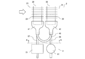
- Embodiment 1 FIG. The heat exchanger according to Embodiment 1 will be described. ⁇ Configuration of heat exchanger> Below, the structure of the heat exchanger which concerns on Embodiment 1 is demonstrated. (Schematic configuration of heat exchanger) Below, schematic structure of the heat exchanger which concerns on Embodiment 1 is demonstrated. 1 is a perspective view of a heat exchanger according to Embodiment 1.
- the heat exchanger 1 includes a heat exchanging unit 2 and a split blending unit 3.
- the heat exchange unit 2 corresponds to the “heat exchange unit” of the present invention.
- the heat exchange unit 2 includes an upwind heat exchange unit 21 disposed on the leeward side and a leeward side disposed on the leeward side in the direction of passage of air passing through the heat exchange unit 2 (the white arrow in the figure). And a heat exchanging unit 31.
- the windward heat exchange unit 21 includes a plurality of windward heat transfer tubes 22 and a plurality of windward fins 23 joined to the plurality of windward heat transfer tubes 22 by, for example, brazing.
- the leeward side heat exchange unit 31 includes a plurality of leeward side heat transfer tubes 32 and a plurality of leeward side fins 33 joined to the plurality of leeward side heat transfer tubes 32 by brazing or the like, for example.
- the heat exchanging unit 2 may be configured by two rows of the windward side heat exchanging unit 21 and the leeward side heat exchanging unit 31, or may be configured by three or more rows.
- the windward side heat transfer tube 22 and the leeward side heat transfer tube 32 are flat tubes, and a plurality of flow paths are formed inside thereof. Each of the plurality of windward side heat transfer tubes 22 and the plurality of leeward side heat transfer tubes 32 is bent in a hairpin shape between one end and the other end to form folded portions 22a and 32a.
- the windward side heat transfer tubes 22 and the leeward side heat transfer tubes 32 are arranged in a plurality of stages in a direction intersecting with the passage direction of air passing through the heat exchanging unit 2 (the white arrow in the figure).
- each of the plurality of windward side heat transfer tubes 22 and the plurality of leeward side heat transfer tubes 32 are arranged in parallel so as to face the mixing / mixing flow portion 3.
- the windward side heat transfer tube 22 and the leeward side heat transfer tube 32 may be circular tubes (for example, a circular tube having a diameter of 4 mm).
- a plurality of channels formed in a flat tube or a channel formed in a circular tube corresponds to the “refrigerant channel” of the present invention.
- the folded portion 22a corresponds to the “first folded portion” of the present invention.
- the folded portion 32a corresponds to the “third folded portion” of the present invention.
- the windward side heat transfer tube 22 and the leeward side heat transfer tube 32 are not bent into a hairpin shape between one end and the other end, and the folded portions 22a and 32a are not formed. And one end of the leeward heat transfer tube 32 and one end of the windward side heat transfer tube 22 and the leeward side heat transfer tube 32 adjacent to the leeward side heat transfer tube 32 are connected members each having a flow path formed therein.
- the refrigerant may be folded back by being connected via the line. In such a case, the flow path formed inside the connecting member corresponds to the “first folded portion” or the “third folded portion” of the present invention.
- the distribution flow unit 3 includes a laminated header 51 and a cylindrical header 61.
- the laminated header 51 and the cylindrical header 61 are arranged side by side so as to follow the passage direction of air passing through the heat exchanging unit 2 (the white arrow in the figure).
- a refrigerant pipe (not shown) is connected to the laminated header 51 via a connection pipe 52.
- a refrigerant pipe (not shown) is connected to the tubular header 61 via a connection pipe 62.
- the connection pipe 52 and the connection pipe 62 are, for example, circular pipes.
- the laminated header 51 is connected to the windward heat exchanging unit 21, and a split flow channel 51 a is formed therein.
- the split-mixing flow channel 51a distributes the refrigerant flowing from the refrigerant pipe (not shown) to the plurality of windward side heat transfer tubes 22 of the windward side heat exchange unit 21. It becomes an outflow distribution channel.
- the split flow channel 51a joins refrigerant flowing in from the plurality of windward side heat transfer tubes 22 of the windward side heat exchange unit 21 to a refrigerant pipe (not shown). It becomes the merging channel that flows out.
- the cylindrical header 61 is connected to the leeward side heat exchanging portion 31 and a split flow channel 61a is formed therein.
- the split flow channel 61a distributes the refrigerant flowing from the refrigerant pipe (not shown) to the plurality of leeward heat transfer tubes 32 of the leeward heat exchange unit 31. It becomes an outflow distribution channel.
- the split-mixing flow channel 61a joins refrigerant flowing in from the plurality of leeward heat transfer tubes 32 of the leeward heat exchange unit 31 to a refrigerant pipe (not shown). It becomes the merging channel that flows out.
- the heat exchanger 1 is a stacked type in which the distribution flow path (split / mixed flow path 51a) is formed and the combined flow path (split / mixed flow path 61a) is not formed when the heat exchanging section 2 acts as an evaporator.
- the header 51 and the cylindrical header 61 in which the merging channel (split / mixed flow channel 61a) is formed and the distribution channel (split / mixed flow channel 51a) is not formed are separately provided.
- the laminated header 51 corresponds to the “first header” of the present invention
- the tubular header 61 corresponds to the “second header” of the present invention.
- the heat exchanger 1 has a cylindrical shape in which a distribution channel (split flow channel 61a) is formed and a merge flow channel (split flow channel 51a) is not formed when the heat exchange unit 2 acts as a condenser.
- the header 61 and the laminated header 51 in which the merging flow path (split flow path 51a) is formed and the distribution flow path (split flow path 61a) is not formed are separately provided.
- the cylindrical header 61 corresponds to a “first header” of the present invention
- the stacked header 51 corresponds to a “second header” of the present invention.
- FIG. 2 is a perspective view of the heat exchanger according to Embodiment 1 in a state where the stacked header is disassembled.
- coolant in case the distribution flow path 51a of the laminated header 51 functions as a distribution flow path is shown by the arrow.
- the third plate-like member 55 formed with is laminated via a plurality of clad members 56_1 to 56_4 in which the partial flow passages 56a are formed, whereby the laminated header 51 is configured.
- a brazing material is applied to both surfaces or one surface of the cladding materials 56_1 to 56_4.
- the first plate member 53, the plurality of second plate members 54_1 to 54_3, the third plate member 55, and the plurality of clad members 56_1 to 56_4 are collectively referred to as “plate members”. May be described.
- the partial flow paths 53a, 55a, and 56a are circular through holes.
- Each of the partial flow paths 54a_1 to 54a_3 is a linear (for example, Z-shaped, S-shaped, etc.) through groove in which the height in the gravity direction of one end and the other end is different from each other.
- a refrigerant pipe (not shown) is connected to the partial flow path 53a through a connection pipe 52.
- the windward heat transfer tube 22 is connected to each of the partial flow paths 55a via the connection pipe 57.
- the connection pipe 57 is, for example, a circular pipe.
- the partial flow path 55 a is a through hole having a shape along the outer peripheral surface of the windward heat transfer tube 22, and the windward heat transfer tube 22 may be directly connected to the through hole without the connection pipe 57.
- the partial flow path 56a of the cladding material 56_1 is formed at a position facing the partial flow path 53a.
- the partial flow path 56a of the cladding material 56_4 is formed at a position facing the partial flow path 55a.
- One end and the other end of the partial flow paths 54a_1 to 54a_3 are opposed to the partial flow paths 56a of the clad members 56_2 to 56_4 laminated adjacent to the side close to the windward heat exchange section 21.
- a portion between one end portion and the other end portion of the partial flow paths 54a_1 to 54a_3 is a partial flow path 56a of the clad material 56_1 to 56_3 laminated adjacent to the side far from the windward heat exchange section 21. Opposite.
- the split flow channel 51a functions as a distribution channel when the refrigerant flows in the direction of the arrow in the figure, and functions as a merging channel when the refrigerant flows in the direction opposite to the arrow in the figure.
- the refrigerant that has flowed into the partial flow channel 53a via the connection pipe 52 passes through the partial flow channel 56a and is at one end of the partial flow channel 54a_1. Between the first end and the other end, hits the surface of the clad material 56_2, and is branched in two directions.
- the branched refrigerant flows out from one end and the other end of the partial flow channel 54a_1, and passes between the one end and the other end of the partial flow channel 54a_2 via the partial flow channel 56a.
- the branched refrigerant flows out from one end and the other end of the partial flow path 54a_2, and passes between the one end and the other end of the partial flow path 54a_3 through the partial flow path 56a. , And hits the surface of the clad material 56_4 to be branched in two directions.
- the branched refrigerant flows out from one end and the other end of the partial flow path 54a_3, and flows into the connection pipe 57 through the partial flow path 56a and the partial flow path 55a.
- the refrigerant that has flowed into the partial channel 55a via the connection pipe 57 passes through the partial channel 56a and is at one end of the partial channel 54a_3. And flows into the other end, and flows into the partial flow path 56a communicating between one end and the other end of the partial flow path 54a_3, thereby being merged.
- the merged refrigerant flows into one end and the other end of the partial flow path 54a_2, and flows into the partial flow path 56a that communicates between one end and the other end of the partial flow path 54a_2. To be merged.
- the merged refrigerant flows into one end and the other end of the partial flow path 54a_1, and flows into the partial flow path 56a that communicates between one end and the other end of the partial flow path 54a_1. To be merged.
- the merged refrigerant flows into the connection pipe 52 through the partial flow path 53a.
- first plate-like member 53, the second plate-like members 54_1 to 54_3, and the third plate-like member 55 may be directly laminated without using the clad members 56_1 to 56_4.
- the partial flow path 56a functions as a refrigerant isolation flow path, so that the refrigerant passing through the partial flow paths 53a, 54a_1 to 54a_3, 55a can be isolated from each other. Ensured.
- Each of the first plate-like member 53, the second plate-like members 54_1 to 54_3, and the third plate-like member 55, and the clad members 56_1 to 56_4 laminated adjacent to each other are integrated into a plate shape.
- the members may be directly laminated.
- FIG. 3 is a perspective view of a cylindrical header of the heat exchanger according to the first embodiment.
- merging flow path is shown by the arrow.
- the cylindrical header 61 includes a cylindrical portion 63 in which one end and the other end are closed so that the axial direction is parallel to the direction of gravity. is there.
- the axial direction of the cylindrical portion 63 may not be parallel to the direction of gravity. Since the cylindrical header 61 is disposed so that the axial direction of the cylindrical portion 63 and the longitudinal direction of the laminated header 51 are parallel to each other, the split flow portion 3 is saved.
- the cylindrical portion 63 may be, for example, a cylindrical portion having an elliptical cross section.
- a refrigerant pipe (not shown) is connected to the side wall of the cylindrical portion 63 via a connection pipe 62.
- the leeward heat transfer tube 32 is connected to the side wall of the cylindrical portion 63 via a plurality of connection pipes 64.
- the connection pipe 64 is, for example, a circular pipe.
- the leeward heat transfer tube 32 may be directly connected to the side wall of the cylindrical portion 63 without using the connection pipe 64.
- the inner side of the cylindrical portion 63 is a split blending flow path 61a.
- the split flow channel 61a functions as a merge channel when the refrigerant flows in the direction of the arrow in the figure, and functions as a distribution channel when the refrigerant flows in the direction opposite to the arrow in the figure.
- the split flow channel 61a functions as a merge channel
- the refrigerant that has flowed into the plurality of connection pipes 64 is merged by passing through the inside of the cylindrical portion 63 and flowing into the connection pipe 62.
- the mixing / mixing flow channel 61 a functions as a distribution channel
- the refrigerant that has flowed into the connection pipe 62 is distributed by passing through the inside of the cylindrical portion 63 and flowing into the plurality of connection pipes 64.
- connection pipe 62 and the plurality of connection pipes 64 are arranged so that the direction in which the connection pipe 62 is connected and the direction in which the plurality of connection pipes 64 are connected are not in a straight line. It is good to be connected. With this configuration, it is possible to improve the uniformity of the refrigerant flowing into the plurality of connection pipes 64 when the mixing / mixing flow path 61a functions as a distribution flow path.
- FIG. 5 is a cross-sectional view taken along line AA in FIG.
- the windward joint member 41 is joined to each of the one end 22 b and the other end 22 c of the windward heat transfer tube 22.
- a flow path is formed inside the windward joint member 41.
- One end of the flow path has a shape along the outer peripheral surface of the windward heat transfer tube 22, and the other end has a circular shape.
- the leeward side joint member 42 is joined to each of the one end portion 32 b and the other end portion 32 c of the leeward side heat transfer tube 32.
- a flow path is formed inside the leeward side joint member 42.
- One end of the flow path has a shape along the outer peripheral surface of the leeward heat transfer tube 32, and the other end has a circular shape.
- the windward joint member 41 joined to the other end 22c of the windward heat transfer tube 22 and the leeward joint member 42 joined to one end 32b of the leeward heat transfer tube 32 are connected to the crossover tube 43.
- the row crossing tube 43 is, for example, a circular tube bent in an arc shape.
- a connection pipe 57 of the laminated header 51 is connected to the windward joint member 41 joined to one end 22 b of the windward heat transfer tube 22.
- a connection pipe 64 of the tubular header 61 is connected to the leeward side joint member 42 joined to the other end 32 c of the leeward side heat transfer tube 32.
- the flow path inside the crossover tube 43 corresponds to the “second folded portion” in the present invention.
- the windward side joint member 41 and the connection pipe 57 may be integrated.
- the leeward side joint member 42 and the connection piping 64 may be integrated.
- the windward side joint member 41, the leeward side joint member 42, and the crossover pipe 43 may be integrated.
- FIG. 6 is a diagram for explaining the connection of the heat exchange unit and the mixing and mixing unit in the modification of the heat exchanger according to the first embodiment. 6 is a cross-sectional view taken along the line AA in FIG. As shown in FIG. 5, the windward side heat transfer tube 22 and the leeward side heat transfer tube 32 include one end 22 b and the other end 22 c of the windward side heat transfer tube 22 and one of the leeward side heat transfer tubes 32.
- the end portion 32b and the other end portion 32c may be arranged in a zigzag shape when the heat exchanger 1 is viewed from the side, and as shown in FIG. You may arrange
- 7 and 8 are diagrams for explaining the connection of the heat exchange unit and the mixing and mixing unit in the modification of the heat exchanger according to the first embodiment.
- 7 and 8 are cross-sectional views taken along the line AA in FIG.
- the other end 22c of the windward heat transfer tube 22, and one end 22b of the windward heat transfer tube 22 adjacent to the windward heat transfer tube 22 are connected by a windward side transition pipe 44, and the other end 32c of the leeward side heat transfer tube 32 and one end 32b of the leeward side heat transfer tube 32 of the next stage of the leeward side heat transfer tube 32 are leeward. It may be connected by a side crossover pipe 45.
- the windward side transition pipe 44 and the leeward side transition pipe 45 are, for example, circular pipes bent in an arc shape.
- the flow path inside the windward side crossover pipe 44 corresponds to the “second folded portion” in the present invention.
- the flow path inside the leeward side crossover tube 45 corresponds to the “second folded portion” in the present invention.
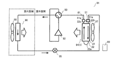
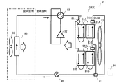
- FIGS. 9 and 10 are diagrams showing a configuration of an air conditioner to which the heat exchanger according to Embodiment 1 is applied.
- FIG. 9 has shown the case where the air conditioning apparatus 91 performs heating operation.
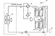
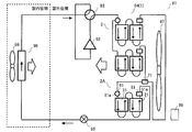
- FIG. 10 shows a case where the air conditioner 91 performs a cooling operation.
- the air conditioner 91 includes a compressor 92, a four-way valve 93, an outdoor heat exchanger (heat source side heat exchanger) 94, an expansion device 95, and an indoor heat exchanger.
- the compressor 92, the four-way valve 93, the outdoor heat exchanger 94, the expansion device 95, and the indoor heat exchanger 96 are connected by a refrigerant pipe to form a refrigerant circulation circuit.
- the four-way valve 93 may be another flow path switching device.
- the outdoor heat exchanger 94 is the heat exchanger 1.
- the heat exchanger 1 is provided such that the laminated header 51 is disposed on the windward side of the air flow generated by driving the outdoor fan 97 and the cylindrical header 61 is disposed on the leeward side.
- the outdoor fan 97 may be provided on the leeward side of the heat exchanger 1 or may be provided on the leeward side of the heat exchanger 1.
- a compressor 92, a four-way valve 93, a throttle device 95, an outdoor fan 97, an indoor fan 98, various sensors, and the like are connected to the control device 99.
- the control device 99 By switching the flow path of the four-way valve 93 by the control device 99, the heating operation and the cooling operation are switched.
- the condensed refrigerant enters a high-pressure supercooled liquid state, flows out of the indoor heat exchanger 96, and becomes a low-pressure gas-liquid two-phase refrigerant by the expansion device 95.
- the low-pressure gas-liquid two-phase refrigerant flows into the outdoor heat exchanger 94, exchanges heat with the air supplied by the outdoor fan 97, and evaporates.
- the evaporated refrigerant enters a low-pressure superheated gas state, flows out of the outdoor heat exchanger 94, and is sucked into the compressor 92 through the four-way valve 93. That is, during the heating operation, the outdoor heat exchanger 94 acts as an evaporator.
- the refrigerant flows into the split flow channel 51 a of the stacked header 51 and is distributed, and flows into one end 22 b of the windward heat transfer tube 22 of the windward heat exchange unit 21.
- the refrigerant that has flowed into one end 22 b of the windward heat transfer tube 22 passes through the turn-back portion 22 a, reaches the other end 22 c of the windward heat transfer tube 22, and exchanges leeward heat through the crossover tube 43. It flows into one end portion 32 b of the leeward heat transfer tube 32 of the portion 31.
- the refrigerant that has flowed into one end portion 32 b of the leeward heat transfer tube 32 passes through the turn-up portion 32 a, reaches the other end portion 32 c of the leeward heat transfer tube 32, and flows into the mixed flow passage 61 a of the tubular header 61. To join.
- the high-pressure and high-temperature gas refrigerant discharged from the compressor 92 flows into the outdoor heat exchanger 94 through the four-way valve 93, exchanges heat with the air supplied by the outdoor fan 97, and condenses.
- the condensed refrigerant enters a high-pressure supercooled liquid state (or a gas-liquid two-phase state having a low dryness), flows out of the outdoor heat exchanger 94, and enters a low-pressure gas-liquid two-phase state by the expansion device 95.
- the low-pressure gas-liquid two-phase refrigerant flows into the indoor heat exchanger 96 and evaporates by heat exchange with the air supplied by the indoor fan 98, thereby cooling the room.
- the evaporated refrigerant becomes a low-pressure superheated gas state, flows out of the indoor heat exchanger 96, and is sucked into the compressor 92 through the four-way valve 93. That is, during the cooling operation, the outdoor heat exchanger 94 functions as a condenser.
- the refrigerant flows into the split flow passage 61a of the cylindrical header 61 and is distributed, and then flows into the other end 32c of the leeward heat transfer tube 32 of the leeward heat exchanger 31.
- the refrigerant that has flowed into the other end portion 32 c of the leeward heat transfer tube 32 passes through the turn-up portion 32 a, reaches one end portion 32 b of the leeward heat transfer tube 32, and exchanges windward heat through the crossover tube 43. It flows into the other end 22c of the windward heat transfer tube 22 of the section 21.
- the refrigerant that has flowed into the other end 22 c of the windward heat transfer tube 22 passes through the turn-back portion 22 a, reaches one end 22 b of the windward heat transfer tube 22, and flows into the mixed flow channel 51 a of the laminated header 51. To join.
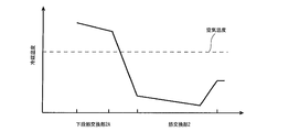
- FIG. 11 is a diagram showing an outline of a change in refrigerant temperature when the heat exchanger according to Embodiment 1 acts as an evaporator.
- FIG. 12 is a diagram showing an outline of a change in refrigerant temperature when the heat exchanger according to Embodiment 1 acts as a condenser. 11 and 12, the change in the refrigerant temperature in the heat exchanger 1 according to Embodiment 1 is indicated by a solid line.
- the heat exchanger in the case where the distribution flow path and the merge flow path are formed in one header is the heat exchanger according to Comparative Example 1, and the change in the refrigerant temperature in the heat exchanger is indicated by a one-dot chain line. Show. Further, the heat exchanger when the distribution flow path and the merge flow path are formed in separate headers, both of which are not stacked headers, is a heat exchanger according to Comparative Example 2, and the heat exchanger A change in the refrigerant temperature is indicated by a dotted line.
- the refrigerant flowing out from the leeward heat exchange section becomes higher in temperature than when flowing into the distribution flow path, and flows into the merge flow path. Since the refrigerant flowing into the merge channel is formed in one header with the distribution channel and the merge channel, the refrigerant is cooled by exchanging heat with the refrigerant before heating that passes through the distribution channel.
- the superheated gas refrigerant flows into the heat exchanger.
- the refrigerant flowing into the distribution channel is cooled by heat exchange with the cooled refrigerant passing through the merge channel because the distribution channel and the merge channel are formed in one header.
- the refrigerant that has passed through the distribution flow path passes through the heat transfer tube of the heat exchanger and the like, enters a supercooled liquid state through the gas-liquid two-phase state, and flows into the merge flow path.
- the refrigerant flowing into the merge channel is heated by exchanging heat with the uncooled refrigerant that passes through the distribution channel because the distribution channel and merge channel are formed in one header.
- the heat exchanger acts as a condenser
- the refrigerant flowing into the merge channel does not exchange heat with the refrigerant before cooling that passes through the distribution channel, and the refrigerant temperature after cooling rises.
- the heat exchange efficiency is improved.
- the heat exchanger 1 since the split flow channel 51a that functions as a distribution flow channel is formed in the laminated header 51, the refrigerant flowing into the split flow channel 61a that functions as a merge channel is further heated. Thus, the heat exchange efficiency is improved. That is, since the laminated header 51 has a larger surface area than a distributor or the like in which a capillary tube is disposed in a part of the flow path, the refrigerant passing through the split flow path 51a is transferred to the windward heat exchange unit 21. Before flowing in, the outdoor fan 97 is heated by the air supplied to the heat exchanger 1 as the outdoor fan 97 is driven.
- the refrigerant passes through the split flow channel 51a while being subdivided, so that the heat transfer performance from the header outer surface to the refrigerant is improved compared to the cylindrical header 61 and the like.
- the refrigerant passing through the split flow passage 51 a is further heated by the air supplied to the heat exchanger 1 as the outdoor fan 97 is driven before flowing into the windward heat exchange unit 21.
- the refrigerant is completely evaporated at an early stage when it passes through the split flow channel 51a, the windward heat transfer tube 22, the leeward heat transfer tube 32, and the like, and the split flow channel that functions as a merged flow channel.
- the refrigerant flowing into 61a becomes even higher in temperature.
- the laminated header 51 is arranged on the windward side as compared with the tubular header 61, the air supplied to the heat exchanger 1 is cooled as the outdoor fan 97 is driven. It will hit the laminated header 51 before, and the refrigerant passing through the split flow channel 51a will be further heated before flowing into the windward heat exchanging section 21, thereby further improving the heat exchange efficiency.
- the laminated header 51 and the tubular header 61 are juxtaposed along the passage direction of the air supplied to the heat exchanger 1 as the outdoor fan 97 is driven, the laminated header 51 becomes the tubular header. 61, the aerodynamic performance of the outdoor fan 97 is improved, and the heat exchanging unit 2 can be enlarged, thereby improving the heat exchange efficiency.
- the split flow channel 51a of the laminated header 51 repeats the bifurcation and distributes the refrigerant, the refrigerant flowing into the plurality of windward side heat transfer tubes 22 and the plurality of leeward side heat transfer tubes 32 is provided. A decrease in uniformity is suppressed. That is, as described above, the refrigerant passing through the split flow channel 51a is heated more than the heat exchanger according to Comparative Example-1 or the heat exchanger according to Comparative Example-2. Approaches 50% and is easily affected by gravity and the like, and it becomes difficult to uniformly distribute the refrigerant to the plurality of windward side heat transfer tubes 22.
- the split flow channel 51a of the laminated header 51 repeats the bifurcation and distributes the refrigerant, even in such a situation, it becomes difficult to be affected by gravity or the like, and a plurality of windward sides It becomes possible to uniformly distribute the refrigerant to the heat transfer tubes 22.
- the split flow channel 51a that functions as the merge channel is formed in the laminated header 51, so that the refrigerant flowing out from the split flow channel 51a that functions as the merge channel is further cooled.
- the heat exchange efficiency is improved. That is, since the laminated header 51 has a larger surface area than a distributor or the like in which a capillary tube is disposed in a part of the flow path, the refrigerant passing through the mixed flow path 51 a is driven by the driving of the outdoor fan 97. Thus, the air is cooled by the air supplied to the heat exchanger 1.
- the refrigerant passes through the mixed flow passage 51a while being gradually merged, so that the heat transfer performance from the header outer surface to the refrigerant is improved as compared with the cylindrical header 61 and the like.
- the refrigerant passing through the split flow channel 51 a is further cooled by the air supplied to the heat exchanger 1 as the outdoor fan 97 is driven.
- the heat exchanger 1 when the heat exchanger 1 acts as a condenser, the refrigerant flows from the plurality of leeward heat transfer tubes 32 to the plurality of leeward heat transfer tubes 22. That is, the passage direction of the air supplied to the heat exchanger 1 with the driving of the outdoor fan 97 and the passage direction of the refrigerant in the row direction of the heat exchange unit 2 are in a counterflow relationship. Therefore, the heat exchange efficiency is improved, and when the heat exchanger 1 acts as a condenser, the difference in refrigerant temperature between the inlet and the outlet of the heat exchanger 1 can be accommodated.
- the split flow channel 61a that functions as a distribution flow channel and the split flow channel 51a that functions as a merge flow channel are formed in separate headers, and the split flow channel 51a that functions as a merge flow channel is a stacked header. Combined with the formation in 51, the heat exchange efficiency is further improved.
- the laminated header 51 is disposed on the windward side as compared with the tubular header 61, the air supplied to the heat exchanger 1 is heated as the outdoor fan 97 is driven. Since it hits the laminated header 51 before, the refrigerant passing through the split flow channel 51a is further cooled, and the heat exchange efficiency is further improved.
- the laminated header 51 and the tubular header 61 are juxtaposed along the passage direction of the air supplied to the heat exchanger 1 as the outdoor fan 97 is driven, the laminated header 51 becomes the tubular header. 61, the aerodynamic performance of the outdoor fan 97 is improved, and the heat exchanging unit 2 can be enlarged, thereby improving the heat exchange efficiency.
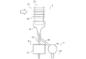
- FIG. 13 is a perspective view of the heat exchanger according to the second embodiment. As shown in FIG. 13, the heat exchange unit 2 has only the windward heat exchange unit 21.
- the windward side heat transfer tubes 22 are arranged in a plurality of stages in a direction intersecting with the passage direction of air passing through the heat exchanging unit 2 (indicated by white arrows in the figure). Each of the plurality of windward side heat transfer tubes 22 is bent in a hairpin shape between one end and the other end to form a folded portion 22a. One end and the other end of each of the plurality of windward side heat transfer tubes 22 are juxtaposed so as to face the laminated header 51.
- the windward heat transfer tube 22 may be a circular tube (for example, a circular tube having a diameter of 4 mm).
- a plurality of channels formed in a flat tube or a channel formed in a circular tube corresponds to the “refrigerant channel” of the present invention.
- the folded portion 22a corresponds to the “first folded portion” of the present invention.
- the laminated header 51 is connected to the windward heat exchanging unit 21, and a split flow channel 51 a is formed therein.
- the split-mixing flow channel 51a distributes the refrigerant flowing from the refrigerant pipe (not shown) to the plurality of windward side heat transfer tubes 22 of the windward side heat exchange unit 21. It becomes an outflow distribution channel.
- the split flow channel 51a joins refrigerant flowing in from the plurality of windward side heat transfer tubes 22 of the windward side heat exchange unit 21 to a refrigerant pipe (not shown). It becomes the merging channel that flows out.
- the cylindrical header 61 is connected to the windward heat exchange unit 21, and a split flow channel 61a is formed therein.
- the split flow channel 61a distributes the refrigerant flowing from the refrigerant pipe (not shown) to the plurality of windward heat transfer tubes 22 of the windward heat exchange unit 21. It becomes an outflow distribution channel.
- the split-mixing flow channel 61a joins refrigerant flowing in from the plurality of windward side heat transfer tubes 22 of the windward side heat exchange unit 21 to a refrigerant pipe (not shown). It becomes the merging channel that flows out.
- the heat exchanger 1 is a stacked type in which the distribution flow path (split / mixed flow path 51a) is formed and the combined flow path (split / mixed flow path 61a) is not formed when the heat exchanging section 2 acts as an evaporator.
- the header 51 and the cylindrical header 61 in which the merging channel (split / mixed flow channel 61a) is formed and the distribution channel (split / mixed flow channel 51a) is not formed are separately provided.
- the laminated header 51 corresponds to the “first header” of the present invention
- the cylindrical header 61 corresponds to the “second header” of the present invention.
- the heat exchanger 1 has a cylindrical shape in which a distribution channel (split flow channel 61a) is formed and a merge flow channel (split flow channel 51a) is not formed when the heat exchange unit 2 acts as a condenser.
- the header 61 and the laminated header 51 in which the merging flow path (split flow path 51a) is formed and the distribution flow path (split flow path 61a) is not formed are separately provided.
- the cylindrical header 61 corresponds to a “first header” of the present invention
- the stacked header 51 corresponds to a “second header” of the present invention.
- FIG.14 and FIG.15 is a figure explaining the connection of the heat exchange part and splitting flow part of the heat exchanger which concerns on Embodiment 2.
- FIG. 15 is a sectional view taken along line BB in FIG.
- the windward joint member 41 is joined to one end 22b and the other end 22c of the windward heat transfer tube 22, respectively.
- a connection pipe 57 of the laminated header 51 is connected to the windward joint member 41 joined to one end 22 b of the windward heat transfer tube 22.
- a connection pipe 64 of the tubular header 61 is connected to the windward joint member 41 joined to the other end 22 c of the windward heat transfer tube 22.
- FIG. 16 is a diagram for explaining the connection of the heat exchange unit and the mixing and mixing unit in a modification of the heat exchanger according to the second embodiment.
- FIG. 16 is a cross-sectional view taken along the line BB in FIG.
- the other end 22 c of the windward heat transfer tube 22 and one end 22 b of the windward heat transfer tube 22 adjacent to the windward heat transfer tube 22 are connected to the windward step. It may be connected by a pipe 44.
- the flow path inside the windward side crossover pipe 44 corresponds to the “second folded portion” in the present invention.
- FIG. 17 is a diagram illustrating a configuration of an air-conditioning apparatus to which the heat exchanger according to Embodiment 2 is applied.
- FIG. 17 has shown the case where the air conditioning apparatus 91 performs heating operation.
- the flow of the refrigerant during the heating operation will be described with reference to FIG.
- the refrigerant flows into the mixed flow passage 51 a of the stacked header 51 and is distributed, and then flows into one end 22 b of the windward heat transfer tube 22 of the windward heat exchange unit 21.
- the refrigerant that has flowed into one end portion 22 b of the windward heat transfer tube 22 passes through the turn-back portion 22 a, reaches the other end portion 22 c of the windward heat transfer tube 22, and flows into the split flow channel 61 a of the tubular header 61.
- FIG. 18 is a diagram illustrating a configuration of an air-conditioning apparatus to which the heat exchanger according to Embodiment 2 is applied.
- FIG. 18 shows a case where the air conditioner 91 performs a cooling operation.
- the flow of the refrigerant during the cooling operation will be described with reference to FIG.
- the refrigerant flows into the split flow passage 61 a of the cylindrical header 61 and is distributed, and then flows into the other end 22 c of the windward heat transfer tube 22 of the windward heat exchange unit 21.
- the refrigerant that has flowed into the other end 22 c of the windward heat transfer tube 22 passes through the turn-back portion 22 a, reaches one end 22 b of the windward heat transfer tube 22, and flows into the mixed flow channel 51 a of the laminated header 51. To join.
- FIG. 3 A heat exchanger according to Embodiment 3 will be described. Note that the description overlapping or similar to the first embodiment and the second embodiment is appropriately simplified or omitted. Moreover, although the case where the heat exchange part 2 of the heat exchanger 1 is comprised in 2 rows like the heat exchanger 1 which concerns on Embodiment 1 below, the heat which concerns on Embodiment 2 is demonstrated. Like the exchanger 1, it may be configured in one row.
- FIG. 19 is a perspective view of a heat exchanger according to the third embodiment.
- the heat exchanging unit 2 is disposed on the lower side in the gravity direction, with the upwind side heat exchange unit 21A and the upwind side heat exchange unit 31A disposed on the upper side in the gravity direction.
- windward upper stage side heat exchange unit 21A and the leeward upper stage side heat exchange unit 31A, and the wind upper and lower stage side heat exchange unit 21B and the leeward lower stage side heat exchange unit 31B are juxtaposed in a direction perpendicular to the direction of gravity, for example. May be.
- the upper laminated header 51A is connected to the upwind side heat exchanging portion 21A, and a split flow channel 51Aa is formed therein.
- the lower laminated header 51B is connected to the wind up / down stage side heat exchanging portion 21B, and a split flow channel 51Ba is formed therein.
- the upper laminated header 51A and the lower laminated header 51B are connected to a distributor 71 in which a capillary is disposed in a part of the flow path.
- the distributor 71 distributes the refrigerant flowing from the refrigerant pipe to the upper laminated header 51A and the lower laminated header 51B.
- the distributor 71 joins and flows out the refrigerant flowing in from the upper laminated header 51A and the lower laminated header 51B to the refrigerant pipe.
- the heat exchange part 2 may be further finely divided, and the distributor 71 may distribute the refrigerant to three or more flow paths.
- a distribution flow path split / mixed flow path 51Aa, split mixed flow path 51Ba
- a combined flow path split / mixed flow path 61a.
- a merged flow channel split flow channel 61a
- a distribution flow channel split flow channel 51Aa, split flow channel 51Ba
- a separate cylindrical header 61 is provided.
- the upper laminated header 51A and the lower laminated header 51B correspond to the “first header” of the present invention
- the tubular header 61 corresponds to the “second header” of the present invention. .
- the heat exchanger 1 when the heat exchanging section 2 acts as a condenser, a distribution channel (split-mix flow channel 61 a) is formed, and a merge flow channel (split-mix flow channel 51 Aa, split-mix flow channel 51 Ba). ) And the upper laminated header 51A in which the merging channel (split-mixing flow channel 51Aa, split-mixing flow channel 51Ba) is formed and the distribution channel (split-mixing flow channel 61a) is not formed.
- the side laminated header 51B is provided separately.
- the tubular header 61 corresponds to the “first header” of the present invention
- the upper laminated header 51A and the lower laminated header 51B correspond to the “second header” of the present invention. .
- FIG. 20 is a diagram illustrating a configuration of an air-conditioning apparatus to which the heat exchanger according to Embodiment 3 is applied.
- FIG. 20 has shown the case where the air conditioning apparatus 91 performs heating operation.
- the flow of the refrigerant during the heating operation will be described with reference to FIG.
- the refrigerant is distributed by the distributor 71, flows into the mixed flow channel 51Aa and the mixed flow channel 51Ba of the upper laminated header 51A and the lower laminated header 51B, and is further distributed. It flows into the upper upper stage side heat exchange part 21A and the wind upper and lower stage side heat exchange part 21B.
- the refrigerant that has passed through the upwind side heat exchange unit 21A and the upside and downside heat exchange unit 21B passes through the upwind side heat exchange unit 31A and the downwind side heat exchange unit 31B, and the combined flow of the cylindrical header 61 It flows into the path 61a and joins.
- FIG. 21 is a diagram illustrating a configuration of an air-conditioning apparatus to which the heat exchanger according to Embodiment 3 is applied.
- FIG. 21 shows a case where the air conditioner 91 performs a cooling operation.
- the flow of the refrigerant during the cooling operation will be described with reference to FIG.
- the refrigerant flows into the split flow passage 61a of the cylindrical header 61 and is distributed, and then flows into the leeward upper stage side heat exchange part 31A and the leeward lower stage side heat exchange part 31B.
- the refrigerant that has passed through the leeward upper stage side heat exchange unit 31A and the leeward lower stage side heat exchange unit 31B passes through the windward upper stage side heat exchange unit 21A and the wind upper and lower stage side heat exchange unit 21B, and the upper laminated header 51A and the lower side It flows into and joins the splitting flow channel 51 ⁇ / b> Aa and splitting flow channel 51 ⁇ / b> Ba of the stacked header 51 ⁇ / b> B, and is further joined by the distributor 71.
- the heat exchanger 1 has an upper laminated header 51A and a lower laminated header 51B, which are connected to the distributor 71.
- the distributor 71 can uniformly distribute the refrigerant, but has a small surface area. Therefore, in the case where the mixing / mixing flow section 3 is configured only by the distributor 71, when the heat exchanger 1 acts as an evaporator, the refrigerant passing through the mixing / mixing flow section 3 cannot be heated, and heat exchange is performed. In the case where the vessel 1 acts as a condenser, the refrigerant passing through the mixing and mixing portion 3 cannot be cooled.
- blending and mixing flow part 3 is comprised with one lamination type header 51 like the heat exchanger 1 which concerns on Embodiment 1, the heat exchange part 2 cannot be divided
- the heat exchanger 1 when the upper laminated header 51A and the lower laminated header 51B are connected to the distributor 71, the surface area is secured and the heat exchange efficiency is improved.
- the heat exchanger 1 acts as an evaporator, the refrigerant can be distributed uniformly, and it is further suppressed that the manufacturing is difficult, and the manufacturing equipment is increased in size. It is suppressed. Moreover, it can respond to the enlargement of the heat exchanger 1 by the increase in the number of sheets, and parts are shared.
- the tubular header 61 distributes the refrigerant in the gas state when the heat exchanger 1 acts as a condenser. Therefore, even if the cylindrical header 61 is divided and they are not connected to the distributor, the uniformity of refrigerant distribution is ensured.
- FIG. 4 A heat exchanger according to Embodiment 4 will be described. Note that descriptions overlapping or similar to the first to third embodiments are appropriately simplified or omitted. Moreover, although the case where the heat exchange part 2 of the heat exchanger 1 is comprised in 2 rows like the heat exchanger 1 which concerns on Embodiment 1 below, the heat which concerns on Embodiment 2 is demonstrated. Like the exchanger 1, it may be configured in one row. Moreover, although the case where the heat exchange part 2 of the heat exchanger 1 is divided
- FIG. 22 is a perspective view of a heat exchanger according to the fourth embodiment.
- the heat exchanger 1 includes a heat exchanging unit 2, a lower heat exchanging unit 2 ⁇ / b> A disposed below the heat exchanging unit 2 in the gravitational direction, a mixing and mixing unit 3, and a mixing and mixing unit. 3A, and a lower-stage blending flow portion 3A disposed below the gravity direction.
- the lower heat exchange unit 2A has the same configuration as the heat exchange unit 2.
- the lower part mixing flow part 3 ⁇ / b> A has the same configuration as the part mixing flow part 3.
- the lower heat exchange part 2A and the lower part blending flow part 3A are shorter in the height direction than the heat exchange part 2 and the part blending flow part 3.
- the heat exchange unit 2 corresponds to the “upper heat exchange unit” of the present invention.
- the lower heat exchange section 2A corresponds to the “heat exchange section” of the present invention.
- connection pipe 52 of the laminated header 51 of the lower heat exchange section 2A is connected to a refrigerant pipe (not shown).
- connection pipe 62 of the cylindrical header 61 of the lower heat exchange unit 2 ⁇ / b> A is connected to the distributor 71.
- a distribution flow path (split mixing flow path 51a) is formed, and a combined flow path (split mixing flow path 61a).
- the cylindrical header 61 is formed separately, and the merged flow path (split and mixed flow path 61a) is formed, and the distribution flow path (split and mixed flow path 51a) is not formed.
- the laminated header 51 corresponds to the “first header” of the present invention
- the tubular header 61 corresponds to the “second header” of the present invention.
- a distribution flow path split flow path 61a
- a combined flow path split flow path 51a
- the merged flow path split and mixed flow path 51a
- the distributed flow path split and mixed flow path 61a
- the cylindrical header 61 corresponds to a “first header” of the present invention
- the stacked header 51 corresponds to a “second header” of the present invention.
- FIG. 23 is a diagram illustrating a configuration of an air-conditioning apparatus to which the heat exchanger according to Embodiment 4 is applied.
- FIG. 23 has shown the case where the air conditioning apparatus 91 performs heating operation.
- the refrigerant flow during the heating operation will be described with reference to FIG.
- the refrigerant is at a higher temperature than the air supplied to the heat exchanger 1 when the outdoor fan 97 is driven, and the mixed flow path of the stacked header 51 of the lower-stage mixed flow section 3 ⁇ / b> A. It flows into 51a, is distributed, and flows into the windward heat exchange unit 21 of the lower heat exchange unit 2A.
- the refrigerant that has flowed into the windward heat exchange section 21 of the lower heat exchange section 2A passes through the leeward heat exchange section 31 of the lower heat exchange section 2A and passes through the split flow path of the cylindrical header 61 of the lower batch mix flow section 3A. It flows into 61a, merges, flows into the distributor 71, and is distributed to the connection pipes 52A and 52B of the heat exchange unit 2.
- FIG. 24 is a diagram illustrating a configuration of an air-conditioning apparatus to which the heat exchanger according to Embodiment 4 is applied.
- FIG. 24 shows a case where the air conditioner 91 performs a cooling operation.
- the flow of the refrigerant during the cooling operation will be described with reference to FIG.
- the refrigerant flows into the distributor 71 from the connection pipes 52A and 52B of the heat exchange unit 2 and is merged, and flows into the mixed flow channel 61a of the cylindrical header 61 of the lower mixed flow unit 3A. It is distributed and flows into the leeward heat exchange section 31 of the lower heat exchange section 2A.
- the refrigerant that has flowed into the leeward heat exchange unit 31 of the lower heat exchange unit 2A passes through the windward heat exchange unit 21 of the lower heat exchange unit 2A, and flows into the mixed flow path of the stacked header 51 of the lower mixed flow unit 3A. It flows into 51a, merges, and flows out into the refrigerant pipe.
- FIG. 25 is a diagram showing an outline of a change in refrigerant temperature when the heat exchanging portion of the heat exchanger according to Embodiment 4 acts as an evaporator.
- the heat exchanging unit 2 acts as an evaporator
- the lower heat exchanging unit is at a higher temperature than the air supplied to the heat exchanger 1 as the outdoor fan 97 is driven.
- the refrigerant flowing into 2A heats the windward side heat transfer tube 22 and the leeward side heat transfer tube 32 of the lower stage heat exchanging part 2A, and the refrigerant temperature decreases.
- the refrigerant that has flowed out of the lower heat exchange section 2A is further reduced in temperature due to the pressure drop caused by the passage of the connection pipe 62, the distributor 71, and the connection pipes 52A and 52B, and the air supplied to the heat exchanger 1 In comparison, the temperature is low.
- the refrigerant that has flowed into the heat exchanging unit 2 is heated by air and completely evaporated, it becomes a superheated gas state, and the refrigerant temperature rises.
- the refrigerant flowing into the distribution flow path passes through the merge flow path.
- Heat exchange with the refrigerant after heating the windward side heat transfer tube 22 and the leeward side heat transfer tube 32 of the exchange unit 2A is suppressed, and the refrigerant temperature is prevented from decreasing before heating, and the above-described refrigeration cycle is performed. The efficiency of improving the quality stability of is improved.
Landscapes
- Engineering & Computer Science (AREA)
- Physics & Mathematics (AREA)
- Thermal Sciences (AREA)
- Mechanical Engineering (AREA)
- General Engineering & Computer Science (AREA)
- Geometry (AREA)
- Heat-Exchange Devices With Radiators And Conduit Assemblies (AREA)
- Other Air-Conditioning Systems (AREA)
Priority Applications (6)
| Application Number | Priority Date | Filing Date | Title |
|---|---|---|---|
| PCT/JP2013/079247 WO2015063857A1 (ja) | 2013-10-29 | 2013-10-29 | 熱交換器、及び、空気調和装置 |
| US15/027,259 US10054376B2 (en) | 2013-10-29 | 2013-10-29 | Heat exchanger and air-conditioning apparatus |
| JP2015544657A JP6091641B2 (ja) | 2013-10-29 | 2013-10-29 | 熱交換器、及び、空気調和装置 |
| AU2013404239A AU2013404239B2 (en) | 2013-10-29 | 2013-10-29 | Heat exchanger and air-conditioning apparatus |
| EP13896696.5A EP3064881B1 (de) | 2013-10-29 | 2013-10-29 | Wärmetauscher und klimaanlage |
| CN201380080610.0A CN105683701A (zh) | 2013-10-29 | 2013-10-29 | 换热器和空调装置 |
Applications Claiming Priority (1)
| Application Number | Priority Date | Filing Date | Title |
|---|---|---|---|
| PCT/JP2013/079247 WO2015063857A1 (ja) | 2013-10-29 | 2013-10-29 | 熱交換器、及び、空気調和装置 |
Publications (1)
| Publication Number | Publication Date |
|---|---|
| WO2015063857A1 true WO2015063857A1 (ja) | 2015-05-07 |
Family
ID=53003508
Family Applications (1)
| Application Number | Title | Priority Date | Filing Date |
|---|---|---|---|
| PCT/JP2013/079247 WO2015063857A1 (ja) | 2013-10-29 | 2013-10-29 | 熱交換器、及び、空気調和装置 |
Country Status (6)
| Country | Link |
|---|---|
| US (1) | US10054376B2 (de) |
| EP (1) | EP3064881B1 (de) |
| JP (1) | JP6091641B2 (de) |
| CN (1) | CN105683701A (de) |
| AU (1) | AU2013404239B2 (de) |
| WO (1) | WO2015063857A1 (de) |
Cited By (12)
| Publication number | Priority date | Publication date | Assignee | Title |
|---|---|---|---|---|
| US20160245560A1 (en) * | 2013-10-29 | 2016-08-25 | Mitsubishi Electric Corporation | Tube fitting, heat exchanger, and air-conditioning apparatus |
| JP2017096550A (ja) * | 2015-11-24 | 2017-06-01 | 株式会社富士通ゼネラル | 熱交換器 |
| JP2017133815A (ja) * | 2016-01-29 | 2017-08-03 | ダイキン工業株式会社 | 熱交換器 |
| WO2017203566A1 (ja) | 2016-05-23 | 2017-11-30 | 三菱電機株式会社 | 分配器、積層型ヘッダ、熱交換器、及び、空気調和装置 |
| WO2018002983A1 (ja) | 2016-06-27 | 2018-01-04 | 三菱電機株式会社 | 冷凍サイクル装置 |
| WO2018029761A1 (ja) * | 2016-08-08 | 2018-02-15 | 三菱電機株式会社 | 積層型ヘッダ、及び積層型ヘッダの製造方法 |
| WO2018138770A1 (ja) * | 2017-01-24 | 2018-08-02 | 三菱電機株式会社 | 熱源側ユニット、及び、冷凍サイクル装置 |
| EP3385643A4 (de) * | 2015-12-01 | 2018-12-05 | Mitsubishi Electric Corporation | Kältekreislaufvorrichtung |
| JP2019132512A (ja) * | 2018-01-31 | 2019-08-08 | ダイキン工業株式会社 | 冷凍装置 |
| WO2020090015A1 (ja) * | 2018-10-30 | 2020-05-07 | 三菱電機株式会社 | 冷媒分配器、熱交換器および空気調和装置 |
| US10753688B2 (en) | 2016-04-07 | 2020-08-25 | Mitsubishi Electric Corporation | Distributer, heat exchanger, and air-conditioning apparatus |
| GB2561098B (en) * | 2015-12-25 | 2021-08-04 | Mitsubishi Electric Corp | Heat exchanger, air-conditioning apparatus including the same, and method of producing flat-tube u-bend |
Families Citing this family (13)
| Publication number | Priority date | Publication date | Assignee | Title |
|---|---|---|---|---|
| US10054376B2 (en) * | 2013-10-29 | 2018-08-21 | Mitsubishi Electric Corporation | Heat exchanger and air-conditioning apparatus |
| JP5949831B2 (ja) * | 2014-05-28 | 2016-07-13 | ダイキン工業株式会社 | 冷凍装置 |
| US10156400B2 (en) * | 2015-01-30 | 2018-12-18 | Mitsubishi Electric Corporation | Heat exchanger and refrigeration cycle device |
| CN209054801U (zh) * | 2016-03-31 | 2019-07-02 | 三菱电机株式会社 | 热交换器以及制冷循环装置 |
| CN106352728A (zh) * | 2016-09-27 | 2017-01-25 | 广东美的制冷设备有限公司 | 连接管组件、换热器组件及空调器 |
| CN106322847A (zh) * | 2016-10-17 | 2017-01-11 | 珠海格力电器股份有限公司 | 多排换热器和包括该多排换热器的空调器 |
| CN106323067A (zh) * | 2016-10-28 | 2017-01-11 | 广东美的制冷设备有限公司 | 连接管组件、换热器组件及空调器 |
| JP6521116B1 (ja) * | 2018-01-31 | 2019-05-29 | ダイキン工業株式会社 | 熱交換器又は熱交換器を有する冷凍装置 |
| JP6985603B2 (ja) * | 2018-01-31 | 2021-12-22 | ダイキン工業株式会社 | 熱交換器又は熱交換器を有する冷凍装置 |
| US11536496B2 (en) * | 2018-10-29 | 2022-12-27 | Mitsubishi Electric Corporation | Heat exchanger and refrigeration cycle apparatus |
| KR102391069B1 (ko) * | 2020-08-25 | 2022-04-28 | 한국에너지기술연구원 | 수직 수평 하이브리드 모듈형 열교환기 |
| US11566845B2 (en) | 2021-03-02 | 2023-01-31 | Evapco, Inc. | Stacked panel heat exchanger for air cooled industrial steam condenser |
| US20240093945A1 (en) * | 2021-03-15 | 2024-03-21 | Mitsubishi Electric Corporation | Heat exchanger and air conditioner |
Citations (9)
| Publication number | Priority date | Publication date | Assignee | Title |
|---|---|---|---|---|
| JPS6380465U (de) * | 1986-11-14 | 1988-05-27 | ||
| JPH0611291A (ja) * | 1992-04-02 | 1994-01-21 | Nartron Corp | 冷却システム用の積層プレートヘッダー及びその製造方法 |
| JPH09189463A (ja) * | 1996-02-29 | 1997-07-22 | Mitsubishi Electric Corp | 熱交換器の分配装置及びその製造方法 |
| JPH10267468A (ja) * | 1997-03-25 | 1998-10-09 | Mitsubishi Electric Corp | 分配ヘッダー |
| JP2000161818A (ja) | 1998-11-25 | 2000-06-16 | Hitachi Ltd | プレート型冷媒分流器およびそれを用いた冷凍サイクル |
| WO2004025207A1 (ja) * | 2002-09-10 | 2004-03-25 | Gac Corporation | 熱交換器およびその製造方法 |
| WO2007063978A1 (ja) * | 2005-12-02 | 2007-06-07 | Showa Denko K.K. | 熱交換器 |
| JP2008286488A (ja) * | 2007-05-18 | 2008-11-27 | Hitachi Appliances Inc | 冷媒分配器 |
| JP2013120039A (ja) * | 2011-12-08 | 2013-06-17 | Samsung Yokohama Research Institute Co Ltd | ヒートポンプシステム |
Family Cites Families (36)
| Publication number | Priority date | Publication date | Assignee | Title |
|---|---|---|---|---|
| US4023618A (en) * | 1975-08-18 | 1977-05-17 | Union Carbide Corporation | Heat exchanger headering arrangement |
| JPH0389463A (ja) * | 1989-08-31 | 1991-04-15 | Aisin Seiki Co Ltd | 鉛蓄電池用極板 |
| US5241839A (en) * | 1991-04-24 | 1993-09-07 | Modine Manufacturing Company | Evaporator for a refrigerant |
| US5479985A (en) * | 1992-03-24 | 1996-01-02 | Nippondenso Co., Ltd. | Heat exchanger |
| US5205347A (en) * | 1992-03-31 | 1993-04-27 | Modine Manufacturing Co. | High efficiency evaporator |
| EP0677716B1 (de) * | 1994-04-12 | 1999-01-07 | Showa Aluminum Corporation | Doppelwärmetauscher in Stapelbauweise |
| JP3444750B2 (ja) | 1997-04-24 | 2003-09-08 | 株式会社日立製作所 | 冷媒分流器 |
| US6810947B2 (en) * | 2001-01-16 | 2004-11-02 | Denso Corporation | Cooling device |
| MXPA04006151A (es) * | 2001-12-21 | 2004-11-01 | Behr Gmbh & Co Kg | Aparato para intercambio de calor. |
| JP2003234590A (ja) * | 2002-02-08 | 2003-08-22 | Denso Corp | 沸騰冷却装置 |
| JP4107051B2 (ja) * | 2002-02-19 | 2008-06-25 | 株式会社デンソー | 熱交換器 |
| JP4055449B2 (ja) | 2002-03-27 | 2008-03-05 | 三菱電機株式会社 | 熱交換器およびこれを用いた空気調和機 |
| JP4120611B2 (ja) * | 2004-04-08 | 2008-07-16 | 株式会社デンソー | 冷媒蒸発器 |
| JP4281634B2 (ja) * | 2004-06-28 | 2009-06-17 | 株式会社デンソー | 冷媒蒸発器 |
| JP2006132920A (ja) * | 2004-07-15 | 2006-05-25 | Showa Denko Kk | 熱交換器 |
| EP2090851A1 (de) * | 2008-02-15 | 2009-08-19 | Delphi Technologies, Inc. | Wärmetauscher mit Mischkammer |
| WO2009105454A2 (en) * | 2008-02-22 | 2009-08-27 | Liebert Corporation | Laminated sheet manifold for microchannel heat exchanger |
| JP2010112695A (ja) * | 2008-10-07 | 2010-05-20 | Showa Denko Kk | エバポレータ |
| JP2012032089A (ja) | 2010-07-30 | 2012-02-16 | Mitsubishi Electric Corp | フィンチューブ型熱交換器及びそれを用いた空気調和機 |
| CN103348212B (zh) * | 2011-01-21 | 2015-06-10 | 大金工业株式会社 | 热交换器及空调装置 |
| US8783057B2 (en) * | 2011-02-22 | 2014-07-22 | Colmac Coil Manufacturing, Inc. | Refrigerant distributor |
| JP5983335B2 (ja) * | 2011-11-30 | 2016-08-31 | 株式会社デンソー | 熱交換器 |
| US10088247B2 (en) * | 2013-05-15 | 2018-10-02 | Mitsubishi Electric Corporation | Stacking-type header, heat exchanger, and air-conditioning apparatus |
| WO2014184915A1 (ja) * | 2013-05-15 | 2014-11-20 | 三菱電機株式会社 | 積層型ヘッダー、熱交換器、及び、空気調和装置 |
| KR20150140836A (ko) * | 2013-05-15 | 2015-12-16 | 미쓰비시덴키 가부시키가이샤 | 적층형 헤더, 열교환기, 및, 공기 조화 장치 |
| CN105209845B (zh) * | 2013-05-15 | 2017-05-03 | 三菱电机株式会社 | 层叠型联管箱、热交换器和空气调节装置 |
| US20160116231A1 (en) * | 2013-05-15 | 2016-04-28 | Mitsubishi Electric Corporation | Stacking-type header, heat exchanger, and air-conditioning apparatus |
| JP5989619B2 (ja) * | 2013-09-13 | 2016-09-07 | 株式会社ティラド | ヘッダープレートレス熱交換器のタンク構造 |
| JP6138264B2 (ja) * | 2013-10-01 | 2017-05-31 | 三菱電機株式会社 | 積層型ヘッダー、熱交換器、及び、空気調和装置 |
| US10054376B2 (en) * | 2013-10-29 | 2018-08-21 | Mitsubishi Electric Corporation | Heat exchanger and air-conditioning apparatus |
| JP6207624B2 (ja) * | 2013-10-29 | 2017-10-04 | 三菱電機株式会社 | 熱交換器、及び、空気調和装置 |
| US10082322B2 (en) * | 2014-10-07 | 2018-09-25 | Mitsubishi Electric Corporation | Heat exchanger and air-conditioning apparatus |
| JP6214789B2 (ja) * | 2014-11-04 | 2017-10-18 | 三菱電機株式会社 | 積層型ヘッダ、熱交換器、及び、空気調和装置 |
| US10156400B2 (en) * | 2015-01-30 | 2018-12-18 | Mitsubishi Electric Corporation | Heat exchanger and refrigeration cycle device |
| WO2016178278A1 (ja) * | 2015-05-01 | 2016-11-10 | 三菱電機株式会社 | 積層型ヘッダ、熱交換器、及び、空気調和装置 |
| CN107367089A (zh) * | 2016-05-13 | 2017-11-21 | 浙江盾安热工科技有限公司 | 微通道换热器 |
-
2013
- 2013-10-29 US US15/027,259 patent/US10054376B2/en active Active
- 2013-10-29 WO PCT/JP2013/079247 patent/WO2015063857A1/ja active Application Filing
- 2013-10-29 AU AU2013404239A patent/AU2013404239B2/en active Active
- 2013-10-29 EP EP13896696.5A patent/EP3064881B1/de active Active
- 2013-10-29 CN CN201380080610.0A patent/CN105683701A/zh active Pending
- 2013-10-29 JP JP2015544657A patent/JP6091641B2/ja active Active
Patent Citations (9)
| Publication number | Priority date | Publication date | Assignee | Title |
|---|---|---|---|---|
| JPS6380465U (de) * | 1986-11-14 | 1988-05-27 | ||
| JPH0611291A (ja) * | 1992-04-02 | 1994-01-21 | Nartron Corp | 冷却システム用の積層プレートヘッダー及びその製造方法 |
| JPH09189463A (ja) * | 1996-02-29 | 1997-07-22 | Mitsubishi Electric Corp | 熱交換器の分配装置及びその製造方法 |
| JPH10267468A (ja) * | 1997-03-25 | 1998-10-09 | Mitsubishi Electric Corp | 分配ヘッダー |
| JP2000161818A (ja) | 1998-11-25 | 2000-06-16 | Hitachi Ltd | プレート型冷媒分流器およびそれを用いた冷凍サイクル |
| WO2004025207A1 (ja) * | 2002-09-10 | 2004-03-25 | Gac Corporation | 熱交換器およびその製造方法 |
| WO2007063978A1 (ja) * | 2005-12-02 | 2007-06-07 | Showa Denko K.K. | 熱交換器 |
| JP2008286488A (ja) * | 2007-05-18 | 2008-11-27 | Hitachi Appliances Inc | 冷媒分配器 |
| JP2013120039A (ja) * | 2011-12-08 | 2013-06-17 | Samsung Yokohama Research Institute Co Ltd | ヒートポンプシステム |
Non-Patent Citations (1)
| Title |
|---|
| See also references of EP3064881A4 |
Cited By (23)
| Publication number | Priority date | Publication date | Assignee | Title |
|---|---|---|---|---|
| US20160245560A1 (en) * | 2013-10-29 | 2016-08-25 | Mitsubishi Electric Corporation | Tube fitting, heat exchanger, and air-conditioning apparatus |
| JP2017096550A (ja) * | 2015-11-24 | 2017-06-01 | 株式会社富士通ゼネラル | 熱交換器 |
| US11105538B2 (en) | 2015-12-01 | 2021-08-31 | Mitsubishi Electric Corporation | Refrigeration cycle apparatus |
| EP3385643A4 (de) * | 2015-12-01 | 2018-12-05 | Mitsubishi Electric Corporation | Kältekreislaufvorrichtung |
| GB2561098B (en) * | 2015-12-25 | 2021-08-04 | Mitsubishi Electric Corp | Heat exchanger, air-conditioning apparatus including the same, and method of producing flat-tube u-bend |
| WO2017130975A1 (ja) * | 2016-01-29 | 2017-08-03 | ダイキン工業株式会社 | 熱交換器 |
| CN108603726A (zh) * | 2016-01-29 | 2018-09-28 | 大金工业株式会社 | 热交换器 |
| JP2017133815A (ja) * | 2016-01-29 | 2017-08-03 | ダイキン工業株式会社 | 熱交換器 |
| US10753688B2 (en) | 2016-04-07 | 2020-08-25 | Mitsubishi Electric Corporation | Distributer, heat exchanger, and air-conditioning apparatus |
| US11226164B2 (en) | 2016-05-23 | 2022-01-18 | Mitsubishi Electric Corporation | Stacked header, heat exchanger, and air-conditioning apparatus |
| WO2017203566A1 (ja) | 2016-05-23 | 2017-11-30 | 三菱電機株式会社 | 分配器、積層型ヘッダ、熱交換器、及び、空気調和装置 |
| EP3467404A4 (de) * | 2016-05-23 | 2019-06-05 | Mitsubishi Electric Corporation | Verteiler, laminiertes kopfteil, wärmetauscher und klimaanlagenvorrichtung |
| WO2018002983A1 (ja) | 2016-06-27 | 2018-01-04 | 三菱電機株式会社 | 冷凍サイクル装置 |
| JPWO2018029761A1 (ja) * | 2016-08-08 | 2019-03-14 | 三菱電機株式会社 | 積層型ヘッダ、及び積層型ヘッダの製造方法 |
| US10921069B2 (en) | 2016-08-08 | 2021-02-16 | Mitsubishi Electric Corporation | Stacking-type header and method of manufacturing stacking-type header |
| US20190154365A1 (en) * | 2016-08-08 | 2019-05-23 | Mitsubishi Electric Corporation | Stacking-type header and method of manufacturing stacking-type header |
| WO2018029761A1 (ja) * | 2016-08-08 | 2018-02-15 | 三菱電機株式会社 | 積層型ヘッダ、及び積層型ヘッダの製造方法 |
| JPWO2018138770A1 (ja) * | 2017-01-24 | 2019-11-07 | 三菱電機株式会社 | 熱源側ユニット、及び、冷凍サイクル装置 |
| WO2018138770A1 (ja) * | 2017-01-24 | 2018-08-02 | 三菱電機株式会社 | 熱源側ユニット、及び、冷凍サイクル装置 |
| JP2019132512A (ja) * | 2018-01-31 | 2019-08-08 | ダイキン工業株式会社 | 冷凍装置 |
| WO2020090015A1 (ja) * | 2018-10-30 | 2020-05-07 | 三菱電機株式会社 | 冷媒分配器、熱交換器および空気調和装置 |
| JPWO2020090015A1 (ja) * | 2018-10-30 | 2021-06-03 | 三菱電機株式会社 | 冷媒分配器、熱交換器および空気調和装置 |
| JP7112164B2 (ja) | 2018-10-30 | 2022-08-03 | 三菱電機株式会社 | 冷媒分配器、熱交換器および空気調和装置 |
Also Published As
| Publication number | Publication date |
|---|---|
| CN105683701A (zh) | 2016-06-15 |
| AU2013404239B2 (en) | 2016-11-03 |
| AU2013404239A1 (en) | 2016-04-28 |
| JPWO2015063857A1 (ja) | 2017-03-09 |
| EP3064881A4 (de) | 2017-07-12 |
| JP6091641B2 (ja) | 2017-03-08 |
| EP3064881A1 (de) | 2016-09-07 |
| EP3064881B1 (de) | 2019-09-11 |
| US10054376B2 (en) | 2018-08-21 |
| US20160245596A1 (en) | 2016-08-25 |
Similar Documents
| Publication | Publication Date | Title |
|---|---|---|
| JP6091641B2 (ja) | 熱交換器、及び、空気調和装置 | |
| JP6207624B2 (ja) | 熱交換器、及び、空気調和装置 | |
| JP6567176B2 (ja) | 積層型ヘッダ、熱交換器、及び、空気調和装置 | |
| JP6333401B2 (ja) | 熱交換器、及び、空気調和装置 | |
| JP6012857B2 (ja) | 積層型ヘッダー、熱交換器、及び、空気調和装置 | |
| JP6336100B2 (ja) | 熱交換器、及び、空気調和装置 | |
| JP6388716B2 (ja) | 積層型ヘッダ、熱交換器、及び、空気調和装置 | |
| JP6116683B2 (ja) | 積層型ヘッダー、熱交換器、及び、空気調和装置 | |
| JP6479195B2 (ja) | 分配器、積層型ヘッダ、熱交換器、及び、空気調和装置 | |
| JP5195733B2 (ja) | 熱交換器及びこれを備えた冷凍サイクル装置 | |
| EP3156752B1 (de) | Wärmetauscher | |
| WO2015111220A1 (ja) | 熱交換器、及び、空気調和装置 | |
| EP3088831B1 (de) | Wärmetauscher und klimaanlage | |
| JP2009150574A (ja) | 分配器、およびそれを搭載した熱交換器並びに空気調和機 | |
| JP5608478B2 (ja) | 熱交換器及びそれを用いた空気調和機 | |
| WO2019130394A1 (ja) | 熱交換器および冷凍サイクル装置 | |
| WO2021245877A1 (ja) | 熱交換器および冷凍サイクル装置 |
Legal Events
| Date | Code | Title | Description |
|---|---|---|---|
| 121 | Ep: the epo has been informed by wipo that ep was designated in this application |
Ref document number: 13896696 Country of ref document: EP Kind code of ref document: A1 |
|
| ENP | Entry into the national phase |
Ref document number: 2015544657 Country of ref document: JP Kind code of ref document: A |
|
| REEP | Request for entry into the european phase |
Ref document number: 2013896696 Country of ref document: EP |
|
| WWE | Wipo information: entry into national phase |
Ref document number: 15027259 Country of ref document: US Ref document number: 2013896696 Country of ref document: EP |
|
| ENP | Entry into the national phase |
Ref document number: 2013404239 Country of ref document: AU Date of ref document: 20131029 Kind code of ref document: A |
|
| NENP | Non-entry into the national phase |
Ref country code: DE |