WO2015037536A1 - 酸化触媒、排ガス処理装置、蓄熱燃焼バーナー、ガス中の可燃成分を酸化する方法及びガス中の窒素酸化物の除去方法 - Google Patents
酸化触媒、排ガス処理装置、蓄熱燃焼バーナー、ガス中の可燃成分を酸化する方法及びガス中の窒素酸化物の除去方法 Download PDFInfo
- Publication number
- WO2015037536A1 WO2015037536A1 PCT/JP2014/073516 JP2014073516W WO2015037536A1 WO 2015037536 A1 WO2015037536 A1 WO 2015037536A1 JP 2014073516 W JP2014073516 W JP 2014073516W WO 2015037536 A1 WO2015037536 A1 WO 2015037536A1
- Authority
- WO
- WIPO (PCT)
- Prior art keywords
- gas
- oxidation catalyst
- catalyst
- pores
- surface area
- Prior art date
- Legal status (The legal status is an assumption and is not a legal conclusion. Google has not performed a legal analysis and makes no representation as to the accuracy of the status listed.)
- Ceased
Links
Images





Classifications
-
- B—PERFORMING OPERATIONS; TRANSPORTING
- B01—PHYSICAL OR CHEMICAL PROCESSES OR APPARATUS IN GENERAL
- B01J—CHEMICAL OR PHYSICAL PROCESSES, e.g. CATALYSIS OR COLLOID CHEMISTRY; THEIR RELEVANT APPARATUS
- B01J23/00—Catalysts comprising metals or metal oxides or hydroxides, not provided for in group B01J21/00
- B01J23/38—Catalysts comprising metals or metal oxides or hydroxides, not provided for in group B01J21/00 of noble metals
- B01J23/40—Catalysts comprising metals or metal oxides or hydroxides, not provided for in group B01J21/00 of noble metals of the platinum group metals
- B01J23/42—Platinum
-
- B—PERFORMING OPERATIONS; TRANSPORTING
- B01—PHYSICAL OR CHEMICAL PROCESSES OR APPARATUS IN GENERAL
- B01D—SEPARATION
- B01D53/00—Separation of gases or vapours; Recovering vapours of volatile solvents from gases; Chemical or biological purification of waste gases, e.g. engine exhaust gases, smoke, fumes, flue gases, aerosols
- B01D53/34—Chemical or biological purification of waste gases
- B01D53/74—General processes for purification of waste gases; Apparatus or devices specially adapted therefor
- B01D53/86—Catalytic processes
- B01D53/8621—Removing nitrogen compounds
- B01D53/8625—Nitrogen oxides
- B01D53/8628—Processes characterised by a specific catalyst
-
- B—PERFORMING OPERATIONS; TRANSPORTING
- B01—PHYSICAL OR CHEMICAL PROCESSES OR APPARATUS IN GENERAL
- B01D—SEPARATION
- B01D53/00—Separation of gases or vapours; Recovering vapours of volatile solvents from gases; Chemical or biological purification of waste gases, e.g. engine exhaust gases, smoke, fumes, flue gases, aerosols
- B01D53/34—Chemical or biological purification of waste gases
- B01D53/74—General processes for purification of waste gases; Apparatus or devices specially adapted therefor
- B01D53/86—Catalytic processes
- B01D53/864—Removing carbon monoxide or hydrocarbons
-
- B—PERFORMING OPERATIONS; TRANSPORTING
- B01—PHYSICAL OR CHEMICAL PROCESSES OR APPARATUS IN GENERAL
- B01J—CHEMICAL OR PHYSICAL PROCESSES, e.g. CATALYSIS OR COLLOID CHEMISTRY; THEIR RELEVANT APPARATUS
- B01J23/00—Catalysts comprising metals or metal oxides or hydroxides, not provided for in group B01J21/00
- B01J23/38—Catalysts comprising metals or metal oxides or hydroxides, not provided for in group B01J21/00 of noble metals
- B01J23/40—Catalysts comprising metals or metal oxides or hydroxides, not provided for in group B01J21/00 of noble metals of the platinum group metals
- B01J23/44—Palladium
-
- B—PERFORMING OPERATIONS; TRANSPORTING
- B01—PHYSICAL OR CHEMICAL PROCESSES OR APPARATUS IN GENERAL
- B01J—CHEMICAL OR PHYSICAL PROCESSES, e.g. CATALYSIS OR COLLOID CHEMISTRY; THEIR RELEVANT APPARATUS
- B01J23/00—Catalysts comprising metals or metal oxides or hydroxides, not provided for in group B01J21/00
- B01J23/38—Catalysts comprising metals or metal oxides or hydroxides, not provided for in group B01J21/00 of noble metals
- B01J23/40—Catalysts comprising metals or metal oxides or hydroxides, not provided for in group B01J21/00 of noble metals of the platinum group metals
- B01J23/46—Ruthenium, rhodium, osmium or iridium
- B01J23/464—Rhodium
-
- B—PERFORMING OPERATIONS; TRANSPORTING
- B01—PHYSICAL OR CHEMICAL PROCESSES OR APPARATUS IN GENERAL
- B01J—CHEMICAL OR PHYSICAL PROCESSES, e.g. CATALYSIS OR COLLOID CHEMISTRY; THEIR RELEVANT APPARATUS
- B01J35/00—Catalysts, in general, characterised by their form or physical properties
- B01J35/60—Catalysts, in general, characterised by their form or physical properties characterised by their surface properties or porosity
- B01J35/64—Pore diameter
- B01J35/647—2-50 nm
-
- B—PERFORMING OPERATIONS; TRANSPORTING
- B01—PHYSICAL OR CHEMICAL PROCESSES OR APPARATUS IN GENERAL
- B01J—CHEMICAL OR PHYSICAL PROCESSES, e.g. CATALYSIS OR COLLOID CHEMISTRY; THEIR RELEVANT APPARATUS
- B01J35/00—Catalysts, in general, characterised by their form or physical properties
- B01J35/60—Catalysts, in general, characterised by their form or physical properties characterised by their surface properties or porosity
- B01J35/64—Pore diameter
- B01J35/651—50-500 nm
-
- B—PERFORMING OPERATIONS; TRANSPORTING
- B01—PHYSICAL OR CHEMICAL PROCESSES OR APPARATUS IN GENERAL
- B01D—SEPARATION
- B01D2255/00—Catalysts
- B01D2255/10—Noble metals or compounds thereof
- B01D2255/102—Platinum group metals
- B01D2255/1021—Platinum
-
- B—PERFORMING OPERATIONS; TRANSPORTING
- B01—PHYSICAL OR CHEMICAL PROCESSES OR APPARATUS IN GENERAL
- B01D—SEPARATION
- B01D2255/00—Catalysts
- B01D2255/20—Metals or compounds thereof
- B01D2255/207—Transition metals
- B01D2255/20707—Titanium
-
- B—PERFORMING OPERATIONS; TRANSPORTING
- B01—PHYSICAL OR CHEMICAL PROCESSES OR APPARATUS IN GENERAL
- B01D—SEPARATION
- B01D2255/00—Catalysts
- B01D2255/90—Physical characteristics of catalysts
- B01D2255/92—Dimensions
- B01D2255/9207—Specific surface
-
- B—PERFORMING OPERATIONS; TRANSPORTING
- B01—PHYSICAL OR CHEMICAL PROCESSES OR APPARATUS IN GENERAL
- B01D—SEPARATION
- B01D2257/00—Components to be removed
- B01D2257/55—Compounds of silicon, phosphorus, germanium or arsenic
- B01D2257/556—Organic compounds
-
- B—PERFORMING OPERATIONS; TRANSPORTING
- B01—PHYSICAL OR CHEMICAL PROCESSES OR APPARATUS IN GENERAL
- B01J—CHEMICAL OR PHYSICAL PROCESSES, e.g. CATALYSIS OR COLLOID CHEMISTRY; THEIR RELEVANT APPARATUS
- B01J21/00—Catalysts comprising the elements, oxides, or hydroxides of magnesium, boron, aluminium, carbon, silicon, titanium, zirconium, or hafnium
- B01J21/06—Silicon, titanium, zirconium or hafnium; Oxides or hydroxides thereof
- B01J21/063—Titanium; Oxides or hydroxides thereof
-
- Y—GENERAL TAGGING OF NEW TECHNOLOGICAL DEVELOPMENTS; GENERAL TAGGING OF CROSS-SECTIONAL TECHNOLOGIES SPANNING OVER SEVERAL SECTIONS OF THE IPC; TECHNICAL SUBJECTS COVERED BY FORMER USPC CROSS-REFERENCE ART COLLECTIONS [XRACs] AND DIGESTS
- Y02—TECHNOLOGIES OR APPLICATIONS FOR MITIGATION OR ADAPTATION AGAINST CLIMATE CHANGE
- Y02A—TECHNOLOGIES FOR ADAPTATION TO CLIMATE CHANGE
- Y02A50/00—TECHNOLOGIES FOR ADAPTATION TO CLIMATE CHANGE in human health protection, e.g. against extreme weather
- Y02A50/20—Air quality improvement or preservation, e.g. vehicle emission control or emission reduction by using catalytic converters
Definitions
- the present invention relates to an oxidation catalyst that oxidizes a combustible component in a gas, an exhaust gas treatment device that uses heat generated when the combustible component in the gas is oxidized, a heat storage combustion burner, a method for oxidizing the combustible component in the gas, and nitrogen oxidation.
- the present invention relates to a method for removing nitrogen oxides.
- wastewater treatment catalysts are often not treated at a high temperature of 500 ° C. or higher during production, and when used for combustion of unburned components in exhaust gas, the properties of the catalyst change during the reaction, There is a risk that strength and catalytic activity may decrease. For this reason, it is difficult to apply the wastewater treatment catalyst as it is to a process for treating unburned components in the exhaust gas.
- the catalysts that can be used in other processes also differ depending on the target reaction and process conditions, and it is difficult to apply these catalysts to oxidative combustion of unburned components in exhaust gas as they are. is there.
- the oxidation catalyst used in the gas to be treated containing sulfur oxide supports a noble metal of 1% by mass or more using a carrier having a surface area of a certain level or more, and the space velocity (unit volume is 1). It is common to cope with this by reducing the volume of the raw material in terms of the standard state passing per hour) to 50000 or less. If the amount of noble metal supported is increased too much, the oxidation of sulfur dioxide to sulfur trioxide increases, but many attempts have been made to suppress the oxidation of sulfur dioxide by adding different elements (for example, the following) (See Patent Documents 5 to 7.)
- JP 2001-336733 A Japanese Patent Laid-Open No. 5-115750 JP 2002-79092 A JP 61-161143 A Japanese Patent No. 4508693 JP 2000-300961 A Japanese Patent Publication No.55-35178
- the present invention suppresses a decrease in the activity of an oxidation catalyst in a gas to be treated containing a catalyst poisonous substance such as sulfur oxide or water vapor while suppressing the amount of metal active species supported, and has a higher space velocity than the prior art.
- An object of the present invention is to provide an oxidation catalyst capable of efficiently oxidizing a combustible substance such as carbon monoxide at a low temperature.
- the present invention uses such an oxidation catalyst to efficiently oxidize a combustible substance such as carbon monoxide at a low temperature in a gas to be treated containing a catalyst poisonous substance.
- the object is to provide a method of oxidation.
- the present invention is an exhaust gas that is filled with such an oxidation catalyst and that can efficiently oxidize a combustible substance such as carbon monoxide even at a low temperature by using heat generated during oxidation of the combustible component in the gas. It is an object of the present invention to provide a treatment apparatus, a heat storage combustion burner, and an efficient nitrogen oxide removal method using such an oxidation catalyst.
- the present inventor has conducted intensive research on a support supporting an active metal and a catalyst supporting an active metal, focusing on specific surface area, pore distribution, constituent elements, and crystal structure. It was.
- the present inventor then pays attention to the pore distribution of the support and the catalyst, and creates a catalyst having a high ratio of pores having a large pore radius, thereby containing a catalyst poisoning substance typified by sulfur oxide.
- a method for suppressing the decrease in the activity of the oxidation catalyst was found, and the present invention was completed.
- the present invention provides the following.
- An oxidation catalyst in which at least one transition element selected from the group consisting of platinum, palladium, and rhodium is supported on a carrier, and the pores having a pore radius in the range of 2 nm to 100 nm in the oxidation catalyst
- the ratio of the surface area formed by pores having a pore radius of 10 nm or more to the total surface area of pores in the range is more than 49%.
- An oxidation catalyst for oxidizing a combustible component in a gas in which at least one transition element selected from the group consisting of platinum, palladium, and rhodium is supported on a carrier, the pore radius in the oxidation catalyst
- the ratio of the surface area formed by pores having a pore radius of 20 nm or more to the total surface area of the pores in the above range is 20% or more, according to any one of (1) to (3) The oxidation catalyst as described.
- the ratio of the surface area formed by pores having a pore radius of 20 nm or more to the total surface area of the pores in the above range is 30% or more, according to any one of (1) to (4) The oxidation catalyst as described.
- the ratio of the surface area formed by pores having a pore radius of 80 nm or more to the total surface area of the pores in the above range is 2% or more, according to any one of (1) to (5) The oxidation catalyst as described.
- the ratio of the transition element supported on the oxidation catalyst is 0.01% or more and 2.0% or less with respect to the total mass of the oxidation catalyst as the sum of the mass ratio of the transition element in terms of metal.
- a combustion catalyst unit for burning unburned components contained in the gas to be treated using a catalyst is provided, and the oxidation catalyst according to any one of (1) to (13) is provided in the combustion catalyst unit
- An exhaust gas treatment device filled with (15) A gas heating unit that is provided upstream of the combustion catalyst unit and increases the temperature of the gas to be processed; and a denitration that is provided downstream of the combustion catalyst unit and removes nitrogen oxides in the gas to be processed.
- An air-fuel mixture injection unit that injects a mixture of fuel and combustion air and a heat storage body are arranged, distribute the gas to be treated to store sensible heat in the heat storage body, and distribute the combustion air after the heat storage
- a heat storage section that heats the combustion air with the amount of heat stored, and the combustion catalyst section provided between the heat storage section and the air-fuel mixture injection section or the heat storage section includes (1) A heat storage combustion burner filled with the oxidation catalyst according to any one of (13) to (13).
- a gas treatment process having a gas heating part for raising the temperature of the gas to be treated and a denitration part for removing nitrogen oxides in the gas to be treated, and containing nitrogen oxides, steam and sulfur oxidation
- a combustion catalyst part filled with the oxidation catalyst described above is disposed, the gas to be treated heated by the gas heating part is passed through the combustion catalyst part, and the combustible component in the gas to be treated is burned.
- a method for removing nitrogen oxides in a gas wherein the temperature of the gas to be treated is further increased by combustion heat.
- a heat exchanger and a gas heating burner or an electric heater are used as the gas heating unit, and the gas discharged from the denitration unit is used as a high-temperature gas of the heat exchanger.
- a heat exchanger and a gas heating burner or an electric heater are used as the gas heating unit, and the position of the combustion catalyst unit is set between the gas heating unit and the denitration unit, and the gas heating unit and the denitration unit.
- the present invention it is possible to oxidize carbon monoxide, nitrogen monoxide, and methane contained in the gas to be treated containing sulfur oxide at a lower temperature than in the prior art, and the metal activity It is possible to provide a catalyst that can be oxidized even when the amount of seed supported is small.
- exhaust gas treatment equipment that uses heat generated during the oxidation of combustible components in the gas, and efficiently oxidize carbon monoxide, nitrogen monoxide, and methane in the gas to be treated And a method for manufacturing such an oxidation catalyst.
- Test Example 1 Comprising: It is a graph which shows the relationship between reaction time and a carbon monoxide conversion rate. It is a figure which shows the result of Test Example 1, Comprising: It is a graph which shows the relationship between reaction time and a carbon monoxide conversion rate. It is a figure which shows the result of Test Example 2, Comprising: It is a graph which shows the relationship between reaction temperature and a carbon monoxide conversion rate. It is a figure which shows the result of Test Example 4, Comprising: It is a graph which shows the relationship between reaction time and a carbon monoxide conversion rate. It is a figure which shows the result of Test Example 5, Comprising: It is a graph which shows the relationship between reaction time and carbon monoxide conversion.
- Factory exhaust gas typified by exhaust gas from a sintering furnace and exhaust gas from a burner contains a large amount of water vapor in addition to sulfur oxides typified by sulfur dioxide and sulfur trioxide.
- sulfur oxides typified by sulfur dioxide and sulfur trioxide.
- sulfur dioxide is oxidized, the amount of sulfur trioxide increases, and concentrated sulfuric acid is generated. It is known that sulfur trioxide and concentrated sulfuric acid easily react with many oxides to form a sulfate, and this reaction is known to greatly impair the activity of the catalyst.
- titanium dioxide and zirconium oxide are known as carriers that are not easily sulfated. It is known that when titanium dioxide is dissolved in concentrated sulfuric acid, a titanium oxide sulfate film is formed on the surface of the titanium dioxide particles, preventing internal sulfation. Moreover, when the ilmenite ore used as the raw material of titanium dioxide is dissolved, it is necessary to raise the temperature of the ilmenite ore to about 1000 ° C. in hot concentrated sulfuric acid.
- titanium dioxide and zirconium oxide show high resistance to sulfur oxides.
- the use of titanium dioxide or zirconium oxide as a carrier can suppress a decrease in activity in the gas to be treated containing sulfur oxides. Absent. This knowledge is as shown in the following experimental example.
- the temperature dependence of the reaction activity was investigated for the catalyst that showed a rapid decrease in activity, it showed a sharp change in activity near 300 ° C, and this activity change was repeatedly observed reversibly by raising and lowering the temperature. It was done.
- Concentrated sulfuric acid is a liquid having a very low vapor pressure and has a boiling point of 300 ° C. or higher.
- the concentrated sulfuric acid produced as a by-product can stably exist as a liquid even in a temperature range below the boiling point.
- it is known that the ease of condensation of concentrated sulfuric acid is greatly influenced by the shape of the carrier.
- the liquid vapor pressure changes depending on the pore radius of the carrier.
- the equilibrium of state change is determined by the change in Gibbs energy and depends on the energy difference before and after the state change.
- the influence of the interfacial energy at the gas-liquid interface increases as the curvature inside the pores increases, and as a result, the partial pressure of the atmospheric pressure in equilibrium with the liquid decreases.
- Such a decrease in partial pressure means that the liquid tends to condense.
- the equation showing this relationship is known as the Kelvin equation and is shown by the following equation.
- the equation of such Kelvin as the pore radius r is reduced, it can be seen that the vapor pressure P is reduced relative to the vapor pressure P o on a plane.
- the meanings of the formulas and symbols used in the formulas are shown below.
- Kelvin's formula: ln (P / P 0 ) ⁇ 2 ⁇ V m COS ⁇ / (rRT) P: Vapor pressure P 0 : Saturated vapor pressure ⁇ : Surface tension [N / m] V m : molar volume [m 3 / mol] r: droplet radius [m] R: Gas constant [J / mol ⁇ K] T: Absolute temperature [K] ⁇ : Contact angle [rad]
- the influence of the shape of the carrier on the condensation of concentrated sulfuric acid is that the gas diffusion rate changes depending on the pore radius.
- the surface of both titanium dioxide and zirconium oxide is sulfated.
- titanium oxide sulfate (IV) produced by sulfating the surface of titanium dioxide, it is in a hydrated state in the range of 400 ° C. or lower.
- sulfur trioxide and water vapor are easily adsorbed. For this reason, these molecules diffuse in the pores while repeating adsorption and desorption, and cause the diffusion to be delayed.
- the gaseous gas species is nitrogen
- the pressure is 1 atm
- the temperature is 523 K
- the mean free path of gas molecules is 100 nm or more. Therefore, in the case of pores of 10 nm or less, collisions between gas molecules are almost ignored, and gas molecules travel in the pores while repeating collisions with the pore wall surfaces (free molecular flow region).
- the present inventor conducted an experiment using a carrier having a high pore ratio with a large pore radius, and the influence of clogging was suppressed, and in a temperature region below the boiling point of concentrated sulfuric acid. Catalytic activity increased, and no steep activity fluctuations near the boiling point of concentrated sulfuric acid were observed. At that time, these phenomena were found to have a strong correlation with the pore distribution.
- a relatively large pore radius of 20 nm or more in order to promote diffusion of sulfur trioxide. It was confirmed that a higher effect can be obtained when the ratio of the pores is high.
- the ratio of the surface area formed by pores having a pore radius of 10 nm or more out of the surface areas formed by pores having a pore radius of 2 nm or more and 100 nm or less is more preferably 50% or more, % Or more is more preferable, and 80% or more is even more preferable.
- the surface areas formed by pores having a pore radius in the range of 2 nm to 100 nm not only the ratio of the surface area formed by pores having a pore radius of 10 nm or more, but also pores having a pore radius of 20 nm or more.
- the ratio of the surface area to be formed is 20% or more, the effect of the present invention can be further exerted, and not only the ratio of the surface area formed by pores having a pore radius of 10 nm or more but also fine pores having a radius of 20 nm or more.
- the ratio of the surface area formed by the holes By setting the ratio of the surface area formed by the holes to 30% or more, the effect of the present invention is more preferably exhibited.
- the ratio of the surface area formed by pores having a pore radius of 80 nm or more is 2% or more among the surface areas formed by pores having a pore radius of 2 nm or more and 100 nm or less.
- the peak of pore distribution is less than a pore radius of 10 nm and is formed by pores having a pore radius of 10 nm or more.
- the ratio of the surface area is small.
- the DH method is one of the methods for calculating the pore distribution.
- the DH method is provided as standard in the analysis software attached to the specific surface area measuring device, and the details are shown in the manual attached to the device. Further, details are shown in many reference books (see, for example, Non-Patent Document 2 above).
- the Barrett-Joyner-Halenda (BJH) method, the Cranston-Inkley (CI) method, etc. are known as methods for obtaining the pore distribution, and the models used for calculation are basically the same in any method. is there.
- the range of the pore radius of 2 nm or more and 100 nm or less the difference between the models is small, and the influence of the measurement error of the apparatus is also small. Therefore, in the present invention, the range of the pore radius to be taken into consideration is limited to the range of 2 nm to 100 nm.
- any method can be used.
- the pore distribution obtained by the analysis using the measurement data in the adsorption process has a stronger correlation with the activity of the catalyst. .
- All the pore distribution analysis methods including the DH method perform calculations based on the difference in nitrogen adsorption amount between two measurement points in the adsorption isotherm measurement process. For this reason, if the measurement interval becomes too wide, the obtained distribution is also greatly increased, and evaluation using the pore distribution cannot be performed. Therefore, it is preferable to perform measurement under the condition that the pore distribution is obtained at intervals of less than 2 nm, particularly for measurement points corresponding to the range of pore radius of 5 nm or more and less than 15 nm. In the range where the pore radius is 15 nm or more and less than 30 nm, the measurement is preferably performed under the condition that the pore distribution is obtained at intervals of less than 5 nm.
- the measurement is preferably performed under the condition that the pore distribution is obtained at intervals of less than 10 nm.
- the measurement is preferably performed under the condition that the pore distribution is obtained at intervals of less than 15 nm. In the following experimental examples, all measurements are performed under these conditions. However, there is no problem if it is determined that a sufficient number of measurements are obtained to determine the state of the pore distribution even when the interval of the pore distribution obtained from this is wide.
- a catalyst having higher activity can be produced by using a carrier having a small pore radius and a large specific surface area.
- the catalytic reaction proceeds on an active point showing catalytic activity.
- the poisoning substance is adsorbed on some or all of these active sites, thereby reducing the proportion of the portion contributing to the catalytic reaction or reducing the activity of adjacent active sites.
- an attempt is made to increase the absolute number of active sites that maintain the activity even in the presence of poisonous substances by increasing the number of active sites.
- the amount of active metal species supported on the carrier is increased.
- a large specific surface area is required.
- a structure with more irregularities is required, and a structure with a small pore radius is required.
- a specific surface area is preferably 50 m 2 / g or less, more preferably by using a carrier having a small specific surface area.
- an oxidation catalyst having a specific surface area of 20 m 2 / g or less is realized.
- titanium dioxide when titanium dioxide was used as a carrier, there was a difference in the activity of the catalyst obtained depending on the type of carrier.
- the rutile type Compared with carriers prepared by the sulfuric acid method, the rutile type has a high tendency for platinum to be oxidized, and a reduction treatment is necessary to obtain high activity.
- the crystal structure of the titanium dioxide support is more preferably an anatase type structure. Titanium dioxide support is often obtained as a mixture of rutile and anatase types, but a mass ratio calculated from the relative ratio of the strongest diffraction lines of powder X-ray diffraction measurement, that 50% or more has an anatase type structure. preferable.
- anatase type structure carrier prepared by the chlorine method and an anatase type structure carrier prepared by the sulfuric acid method are compared.
- a carrier prepared by the chlorine method is used.
- platinum the prepared platinum was oxidized, and the activity could not be obtained without reduction treatment.
- any reaction proceeds on the metal surface (see, for example, Non-Patent Document 4 above).
- the reactants do not come into contact with the noble metal in the first place, and the activity is reduced in any reaction under the condition of pore clogging.
- an oxidation reaction examples include oxidation reactions of carbon monoxide, nitrogen monoxide, and methane. In any of these oxidation reactions, it is known that the reaction proceeds on the surface of the noble metal and the reaction does not easily proceed in the absence of the noble metal.
- the active metal species is not particularly limited, but if it reacts easily with sulfur dioxide, the active species itself loses its activity even if pore clogging does not occur, and the activity cannot be obtained.
- metal species having high activity as an oxidation catalyst for example, cobalt, nickel, copper, ruthenium, rhodium, palladium, platinum, gold and the like are known.
- the standard generation enthalpy of oxide can be used as an index as a substance that hardly reacts with sulfur dioxide to form sulfur oxide, and it can be determined that the smaller the absolute value of the standard generation enthalpy is, the less the substance is oxidized.
- the standard generation enthalpy value is published not only in books but also in databases on the Internet (for example, see Non-Patent Document 5 above).
- gold, platinum, palladium and rhodium are preferable as the active metal species, and platinum and gold are particularly preferable.
- a catalyst supporting gold alone has a high oxidation activity at the interface between the gold fine particles and the oxide carrier, and the surface of the oxide carrier is sulfated, so that it is highly active. Decreases. Therefore, when using gold, it is more preferable to use in combination with other transition metals or to use platinum.
- the surface of palladium or rhodium particles is covered with platinum and used as a core-shell structure, so that the formation of sulfate can be suppressed.
- the amount of platinum used can be reduced, and the cost can be reduced.
- the amount of the active metal species supported is not particularly limited, but is limited from an economical viewpoint.
- the loading amount increases, the active point increases and the catalytic activity increases, while the particle size of the supported metal fine particles increases, and the proportion of the portion that does not contribute to the reaction tends to increase.
- the noble metal particles themselves cause clogging / stenosis of the pores and the influence of the clogging of the pores due to the concentrated sulfuric acid is likely to occur, the proportion of the portion that does not contribute to the reaction further increases.
- the loading amount is 0.01 mass. % Or more is preferable.
- all of the catalysts exhibiting high sulfur resistance according to the present invention have a specific surface area of 50 m 2 / g or less, so that the platinum loading is 2.0 mass% or less. It is considered that finer platinum particles can be achieved, which is preferable.
- the oxidation catalyst of the present invention exhibits high activity in many gases to be treated, but the effect is exhibited particularly in a gas containing sulfur oxide and water vapor.
- a gas containing sulfur oxide and water vapor When the oxidation reaction proceeds in a state where these gases are contained in the gas to be treated, concentrated sulfuric acid is generated as a side reaction regardless of the concentration, and pores are blocked. By suppressing the effect of this pore blockage, it is expected that the decrease in activity is suppressed.
- the volume ratio of the sulfur oxide in the gas to be treated is preferably smaller than at least the sum of the volume ratios of carbon monoxide, nitrogen monoxide, and methane.
- the temperature of the gas to be treated it is expected that the activity equal to or higher than that of the conventional catalyst can be obtained at any temperature.
- the reaction temperature is raised to be higher than the boiling point of concentrated sulfuric acid, there is a difference due to the difference in pore radius. Hard to come out.
- the boiling point of concentrated sulfuric acid varies greatly depending on its concentration and is also influenced by the concentration of water vapor in the gas to be treated, so it is difficult to determine uniquely.
- the sum of the partial pressures of water vapor and hydrosulfuric acid is 1 atm or higher in concentrated sulfuric acid of all concentrations (see, for example, Non-Patent Document 8 above).
- the reaction temperature is preferably at least 400 ° C. or lower.
- reaction temperature is too low, the reaction will not proceed in the first place, and it will be necessary to increase the amount of catalyst, leading to an increase in cost.
- the reaction temperature is increased to about 200 ° C. It is known (see, for example, Non-Patent Document 9 above). Therefore, also in the method according to the present invention, it is preferable to increase the reaction temperature to 200 ° C. or higher.
- the reaction temperature is more preferably 250 ° C. or higher from the viewpoint of increasing the reaction rate and suppressing the necessary amount of catalyst. Further, as shown in the following experimental examples, the effect of the present invention becomes difficult to obtain at a temperature of 300 ° C. or higher, and therefore the reaction temperature is more preferably 300 ° C. or lower.
- the method for supporting the active metal species is not particularly limited, but it is considered that the precipitation reduction method avoids excessive heat treatment on the support and easily obtains the expected pore distribution.
- the precipitation reduction method avoids excessive heat treatment on the support and easily obtains the expected pore distribution.
- a platinum-supported catalyst is often obtained by performing calcination treatment at about 500 ° C. using chloroplatinic acid as a precursor. Therefore, it is preferable to use a carrier having a small structural change when the temperature is raised to 500 ° C.
- a carrier having a Tamman temperature of 500 ° C. or more which is an empirical indicator that atoms on the solid surface start to diffuse. Since the Tamman temperature is an empirical expression that is about 1 ⁇ 2 of the melting point in absolute temperature notation, it is preferable to use a carrier having a melting point of 1300 ° C. or higher. Examples of such carriers include titanium dioxide, zirconium oxide, aluminum oxide, silicon dioxide and the like.
- titanium dioxide When titanium dioxide is used as a carrier, titanium dioxide tends to cause a phase transition, so that the pore distribution changes when the firing temperature is not appropriate.
- the ratio of the pores having a small pore radius increases.
- the specific surface area decreases, the number of pores having a pore radius of 10 nm or less decreases, and the pore radius of pores having a pore radius of 10 nm or more is reduced. Changes in the direction of decreasing. This changes the relationship between the pore radius and the specific surface area.
- a carrier having pores having a sufficiently large pore radius so that the specific surface area of pores having a pore radius of 10 nm or more is kept large even if the pore distribution changes.
- the heat treatment is performed in advance and the noble metal precursor is devised to avoid heating to 650 ° C. or higher.
- a noble metal precursor for example, when gold is used, gold chloride (III) acid hydrate is suitable, and when platinum is used, platinum chloride (IV) acid hydrate is suitable, When palladium is used, diammine dinitropalladium (II) or the like is preferable, and when rhodium is used, rhodium (III) chloride hydrate or the like is preferable.
- an exhaust gas treatment apparatus having a combustion catalyst unit for burning unburned components in exhaust gas containing water vapor using a catalyst having the above properties. That is, the oxidation catalyst according to the present invention is filled in the combustion catalyst portion provided in the exhaust gas treatment apparatus.
- This exhaust gas treatment device is used as a removal device for unburned components such as carbon monoxide and nitrogen oxides, exhaust heat recovery equipment that recovers and uses the amount of heat generated by combustion of unburned components, or as an energy saving process. Can be applied.
- the oxidative combustion reaction of the unburned components performed using the oxidation catalyst according to the present embodiment is performed under a pressure of about normal pressure to about 0.2 MPa. Since the reaction is carried out at normal pressure to about 0.2 MPa, it is preferable that the direction of travel of the exhaust gas in the combustion catalyst section is the horizontal direction or the direction from the upper side to the lower side in the vertical direction. Further, in the combustion catalyst part of such an exhaust gas treatment device, the reaction proceeds using the sensible heat of the exhaust gas, and unlike the waste water treatment process, it is not necessary to heat the combustion catalyst part itself.
- the filling method of the oxidation catalyst according to the present invention in the combustion catalyst section is not particularly limited, and various known methods such as filling the oxidation catalyst according to the present invention into a honeycomb shape may be used. Can be used. At this time, the transition element as described above may be supported on the support formed in the honeycomb shape, and after adding various binders to the above oxidation catalyst, the oxidation catalyst itself is added to the honeycomb. You may form in a shape.
- an exhaust gas denitration method including a combustible gas.
- This heating is usually performed using combustion heat such as natural gas.
- the cost can be reduced by substituting the heating with the combustion heat of the combustible gas component obtained by the oxidation catalyst according to the present invention.
- the process shown in FIG. 1 includes a heat exchange unit 1, a gas heating burner 2 that is an example of a gas heating unit provided at the subsequent stage of the heat exchange unit 1, and a combustion catalyst provided at the subsequent stage of the gas heating burner 2.
- Part 3 and a denitration device part 4 which is an example of a denitration part provided at the rear stage of combustion catalyst part 3.
- the exhaust gas introduced into the heat exchange unit 1 is heat-exchanged using heat generated in the subsequent denitration device unit 4 and then flows into the gas heating burner 2.
- the exhaust gas heated by the gas heating burner 2 flows into the combustion catalyst section 3 filled with the oxidation catalyst according to the present invention, and the unburned components contained in the exhaust gas are oxidized and burned by the oxidation catalyst according to the present invention.
- the exhaust gas is further heated by the generated combustion heat.
- the exhaust gas combusted with the unburned components flows into the denitration unit 4 together with ammonia, and the reaction between ammonia and nitrogen oxide proceeds by the denitration catalyst. Further, the exhaust gas after the denitration process is supplied to the heat exchanging unit 1 for heat exchange.
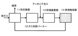
- the process shown in FIG. 2 includes a heat exchange unit 11, a gas heating burner 12 that is an example of a gas heating unit provided at the subsequent stage of the heat exchange unit 11, and a denitration process that is provided at the subsequent stage of the gas heating burner 12.
- the denitration device unit 13, which is an example of the unit, and the combustion catalyst unit 14 provided at the subsequent stage of the denitration device unit 13 are provided.
- the exhaust gas introduced into the heat exchange unit 11 is heat-exchanged using the combustion heat generated in the combustion catalyst unit 14 at the subsequent stage, and then flows into the gas heating burner 12.
- the exhaust gas heated by the gas heating burner 12 flows into the denitration unit 13 together with ammonia, and the reaction between ammonia and nitrogen oxide proceeds by the denitration catalyst.
- the exhaust gas that has undergone the denitration treatment flows into the combustion catalyst section 14 filled with the oxidation catalyst according to the present invention, and the unburned components contained in the exhaust gas that has undergone the denitration treatment are oxidized and combusted by the oxidation catalyst according to the present invention. Is done.
- the generated combustion heat is supplied to the heat exchange unit 1.
- the installation location of the combustion catalyst unit may be either upstream or downstream of the denitration device. Since the temperature required to advance the reaction in the denitration catalyst unit is constant, in the process of FIG. 1, the reaction temperature at the inlet of the combustion catalyst unit is 200 to 250 ° C. In the process of FIG. The reaction temperature at the entrance of the combustion catalyst section is about 250 to 300 ° C.
- exhaust gas treatment equipment examples include regenerative burners and radiant tube heat storage combustion burners.
- the process in these heat storage combustion burners is a process in which one set of a burner and a heat storage body is used as a pair, and the exhaust heat of exhaust gas when burner injection is performed in one set is stored in the other heat storage body. .
- FIG. 3 shows an outline of the process in such a heat storage combustion burner.
- Such a process injects, as main components, an exhaust air flow path switch 21, a heat storage section 22a, 22b containing a heat storage body and a combustion catalyst, a fuel gas supply section 23a, 23b, and a mixture of combustion air and fuel gas.
- the air-fuel mixture injection sections 24a and 24b, a space 25 heated by burner injection, an air introduction path 26, and an exhaust gas path 27 are provided.
- the oxidation catalyst which concerns on this invention is utilized for the combustion catalyst contained in the thermal storage part 22a, 22b. That is, in the heat storage combustion burner shown in FIG. 3, it can be said that the heat storage portions 22a and 22b are composed of a heat storage body and a combustion catalyst portion.
- FIG. 3 shows a process in the case of performing burner injection at the mixture injection section 24a and taking out the exhaust gas from the mixture injection section 24b.
- Such a burner controls the exhaust air flow path switch 21 to introduce air into the heat storage section 22a from the air introduction path 26, and the air heated by the heat storage section and the fuel gas supplied from the fuel gas supply section 23a. Are injected from the mixture injection section 24a. Then, the exhaust gas discharged through the air-fuel mixture injection unit 24b is introduced into the heat storage unit 22b, the air introduced from the secondary air introduction unit 28b and the unburned components in the exhaust gas are burned by the combustion catalyst, After the obtained heat is stored in the heat storage unit 22b, the exhaust gas is exhausted from the exhaust gas passage 27.
- the exhaust air switch 21 is switched to reverse the flow of the heat storage units 22a and 22b and the burner injection units 24a and 24b.
- combustion heating is performed on the oxidation catalyst using unburned components in the exhaust gas injected from the air-fuel mixture injection units 24a and 24b, and the amount of sensible heat stored in the heat storage body is increased. Can be improved.
- the temperature of the heat accumulators 22a and 22b in a general burner is higher at a portion closer to the space 25 and reaches about 1200 ° C. at the highest, while the temperature is lower at a portion closer to the exhaust air flow path switching device 21 and at the highest. It reaches only about 250 ° C.
- the combustion catalyst filled in the heat storage units 22a and 22b is preferably filled in a portion where the maximum temperature reaches less than 600 ° C, and more preferably a portion where the temperature reaches less than 500 ° C. .
- the time when the temperature is lower than 300 ° C. becomes longer in a portion having a relatively low temperature range. Therefore, by using the oxidation catalyst according to the present invention as a combustion catalyst, it is possible to obtain the effect of preventing the decrease in activity due to concentrated sulfuric acid.
- the structure of the heat storage combustion burner according to the present invention is not limited to the above structure.
- the heat storage body and the fuel catalyst part filled with the oxidation catalyst according to the present invention are installed in the same place, but the heat storage body and the combustion catalyst part are divided as separate components, The heat storage unit and the fuel catalyst unit may be independent from each other.
- FIG. 3 illustrates a case where the heat storage unit includes two systems. However, the flow path is branched from the exhaust air switching device 21 into three or more systems so as to have three or more heat storage units. A configuration may be adopted in which a plurality of flow paths are switched simultaneously.
- the application destination of the exhaust heat recovery equipment using the exhaust gas treatment apparatus of the present invention is not limited to the exhaust gas denitration method and the heat storage combustion burner described above, but also applies to the exhaust heat recovery apparatus in other processes. Can do.
- Titanium oxide support TIO-2 reference catalyst
- titanium oxide support TIO-6 reference catalyst
- zirconium oxide support ZRO-4 reference catalyst
- titanium oxide support TIO-4 reference catalyst
- Titanium oxide support TIO-8 catalyst society reference catalyst
- titanium oxide support TIO-7 catalysis society reference catalyst
- titanium oxide support ST-01 Ishihara Sangyo
- titanium oxide support FTL-110 Ishihara Sangyo
- Titanium oxide support FTL-200 Ishihara Sangyo
- zirconium oxide support ZRO-3 catalyst society reference catalyst
- aluminum oxide support ALO-1 catalysis society reference catalyst
- the shape of the carrier is powdery.
- the physical properties of the carriers 1 to 8 are summarized in Table 1 below.
- the crystal structure of the carrier was determined by powder X-ray diffraction measurement, and when possible, the abundance ratio was calculated using the relative intensity of the strongest diffraction line of each phase.
- Specific surface area was determined by BET method using nitrogen adsorption isotherm at liquid nitrogen temperature, and pore distribution was determined by DH method using data of adsorption process. The pore volume was calculated using the value of the relative partial pressure 0.99 of the adsorption isotherm. Thereafter, in all Examples and Comparative Examples, physical property values were obtained in the same manner.
- Example 1 platinum-supported catalyst
- 0.00265 g of hexachloroplatinic acid was dissolved in 0.20 ml, 0.45 ml, 0.20 ml, and 0.35 ml of pure water.
- the obtained platinum precursor solution was added dropwise to 1.00 g of each of the oxide carriers 1 to 5 while being sufficiently mixed, and impregnated.
- the obtained powder was calcined at 100 ° C. for 10 hours and at 500 ° C. for 1 hour, and the obtained catalysts were used as Samples 1 and 4-7.
- the amount of platinum supported was 0.1% by mass in terms of platinum in the metal state.
- FIG. 4A to FIG. 4C show cumulative values of the ratio (A r / A 2-100 nm ) of the surface area formed by the pores having the respective pore radii below the surface area formed by the pores in the range.
- Table 2 shows values obtained by calculating the ratio of the surface area formed by pores having a pore radius of 10 nm or more out of the surface areas formed by pores having a pore radius of 2 nm or more and 100 nm or less. This value was calculated by subtracting from 100 the value of A r / A 2-100 nm at a pore radius of 10 nm.
- Example 2 Palladium-supported catalyst
- Dinitrodiammine palladium (Kojima Chemical) 0.00220 g was dissolved in 15 ml of nitric acid, and 1.00 g of oxide carrier 1 of carrier 1 was added. After stirring for 1 hour, the mixture was stirred on a hot stirrer at 80 ° C. and evaporated to dryness. The obtained solid was dried at 120 ° C. for 10 hours in the air, then heated to 400 ° C. and calcined for 30 minutes. The catalyst obtained after cooling was designated as Sample 2.
- Table 2 shows the physical property values of Sample 2 measured in the same manner as in Example 1.
- Example 3 Rhodium supported catalyst
- Rhodium (III) chloride trihydrate 0.00256 was dissolved in 0.20 ml of pure water.
- the obtained aqueous rhodium precursor solution was added dropwise to 1.00 g of the oxide carrier of carrier 1 while being sufficiently mixed, and impregnated.
- the obtained powder was calcined at 100 ° C. for 10 hours and at 500 ° C. for 1 hour, and the obtained catalyst was used as Sample 3.
- the supported amount of rhodium was 0.1% by mass in terms of rhodium in the metal state.
- Table 2 shows the physical property values of Sample 3 measured in the same manner as in Example 1.
- Example 4 Low supported platinum supported catalyst 0.00265 g of hexachloroplatinic acid was dissolved in 1.0 ml of pure water. 0.30 ml of the obtained platinum precursor solution was added dropwise to 1.00 g of each oxide carrier of carrier 1 while being sufficiently mixed, and impregnated. The obtained powder was calcined at 100 ° C. for 10 hours and at 500 ° C. for 1 hour, and the obtained catalyst was used as Sample 8. The amount of platinum supported was 0.03% by mass in terms of platinum in the metal state. Table 2 shows the physical property values of Sample 8 measured in the same manner as in Example 1.
- Example 5 High supported platinum supported catalyst
- Hexachloroplatinic acid 0.02589 g and 0.05178 were dissolved in 0.45 ml of pure water, respectively.
- Each of the obtained platinum precursor solutions was dropped and impregnated while being sufficiently mixed with 1.00 g of the oxide carrier of the carrier 2.
- the obtained powder was calcined at 100 ° C. for 10 hours and at 500 ° C. for 1 hour, and the obtained catalysts were used as Samples 9 and 10, respectively.
- the supported amounts of platinum were 1% by mass and 2% by mass, respectively, in terms of platinum in the metal state.
- Table 2 shows physical property values of Samples 9 and 10 measured in the same manner as in Example 1.
- FIG. 5A to FIG. 5C show the ratio (A r / A 2-100 nm ) of the surface area formed by the pores having the pore diameters or less among the surface areas formed by the pores.
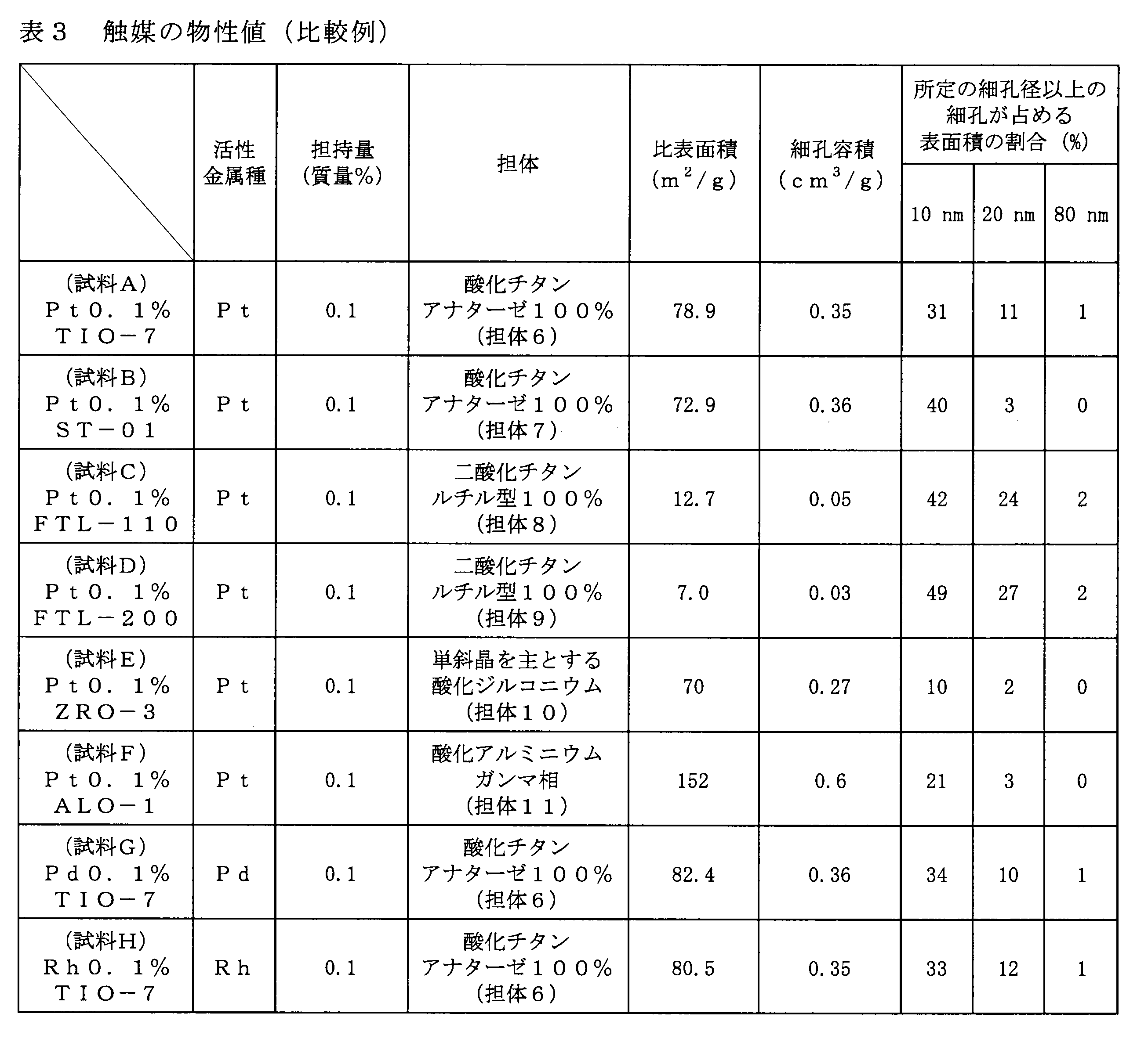
- Table 3 shows the physical property values of Samples A to F measured in the same manner as in Example 1.
- Rhodium (III) chloride trihydrate 0.00256 was dissolved in 0.20 ml of pure water.
- the obtained rhodium precursor aqueous solution was added dropwise to 1.00 g of the oxide carrier of the carrier 6 while being sufficiently mixed, and impregnated.
- the obtained powder was calcined at 100 ° C. for 10 hours and at 500 ° C. for 1 hour, and the obtained catalyst was used as sample H.
- the supported amount of rhodium is 0.1% by mass in terms of rhodium in the metal state.
- Table 3 shows the physical property values of Sample H measured in the same manner as in Example 1.
- the space velocity indicating the relative ratio of gas and catalyst amount is approximately 600000 cm 3 ⁇ hour ⁇ 1 ⁇ catalyst mass (g) ⁇ 1 .
- the value of the space velocity used for the reaction is about 1/10 of the space velocity. It was decided to demonstrate the high stability of the catalyst of the present invention by conducting the activity test at a space velocity higher than a general value.
- the gas flow rate and composition are adjusted using a mass flow controller, and the gas cylinder as a gas source is carbon monoxide 5% + nitrogen 95%, sulfur dioxide 200 ppm + nitrogen monoxide 200 ppm + nitrogen balance, oxygen (purity 99.9999 or more) And four types of nitrogen (purity 99.9999% or more) were prepared.
- the water vapor was adjusted by introducing a required amount of pure water with a water pump. Thereafter, the gas composition was adjusted in the same manner in all tests.
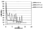
- FIG. 6A to FIG. 6D The results of the reaction test are shown in FIG. 6A to FIG. 6D.
- Samples 9 and 10 are not shown in FIGS. 6A to 6D, the carbon monoxide conversion rate remained at 100% from the start to the end of the reaction in both cases.
- Samples 1 and 4 to 10 of the invention example and Samples A to F of the comparative example have a great difference in time dependency of the conversion rate of carbon monoxide.
- Samples 1 and 4 to 10 have a reaction time of 15 hours. However, it can be seen that in Samples A to F, the activity decreased greatly after 15 hours.
- Sample 6 has a lower activity at the time point of 15 hours than Samples 1, 4, and 5 of the invention, and sample 7 has an unstable activity.
- the ratio of the surface area formed by pores having a pore radius of 10 nm or more is lower in Sample 6 than in the other invention examples, and the pore radius is 10 nm or more. It is considered that a higher carbon monoxide conversion is obtained as the ratio of the specific surface area formed by the pores is larger.
- the ratio of the surface area formed by pores having a pore radius of 20 nm or more is high although the ratio of the surface area formed by pores having a pore radius of 10 nm or more is high.
- the ratio is significantly lower than that of Samples 1 and 4-6. It can also be seen that the ratio of the surface area formed by pores having a pore radius of 80 nm or more is lower than that of Samples 1 and 4-6.
- the surface area formed by pores having a pore radius of 10 nm or more in addition to a large proportion of the surface area formed by pores having a pore radius of 10 nm or more, the surface area formed by pores having a pore radius of 20 nm or more. It can be seen that a higher ratio is more preferable. It can also be seen that a higher proportion of the surface area formed by pores having a pore radius of 80 nm or more is more preferable.
- Sample B a phenomenon in which the activity increases intermittently even after the carbon monoxide conversion rate once decreases is observed.
- the pore distribution of sample B slightly changes, and in the pores in the range of pore radius of 2 nm to 100 nm, the surface area of the pores having a pore radius of 10 nm or more occupying the total surface area of the pores in this range. If the ratio exceeds 40%, a significant decrease in activity may be avoided.
- samples C and D Is expected to be higher in stability than sample B, but samples C and D have a significantly smaller pore volume than sample B, so it is considered that the time required to close the pores is shorter.
- the alumina carrier itself reacts with concentrated sulfuric acid to become a sulfate.
- the alumina carrier reacts with concentrated sulfuric acid to form sulfate, and the amount of sulfate remaining as concentrated sulfuric acid is relatively reduced. It is considered that the time required for the carbon monoxide conversion rate to decrease is increased due to these factors.
- Each 1 mg of each of the three types of catalysts was diluted by mixing 30 mg of carriers 1, 2, and 7 and filled in quartz glass tubes.
- the difference between the example and the comparative example is large, and it can be seen that the catalytic activity of the sample B is very low.
- the influence of pore clogging has become obvious. Also from these points, it is considered that in the Examples, the influence of pore clogging by concentrated sulfuric acid is small, and high activity is obtained.
- the supported amount of platinum is 0.03% by mass or less
- the platinum fine particles are present as fine particles having a critical particle size
- the supported amount of noble metal is 0.03% by mass or less
- the effect of the present invention is exhibited even with a catalyst having a loading amount of 0.01%, and the activity in the range of 300 ° C. or lower can be achieved by using a catalyst having a high surface area ratio occupied by pores having a pore radius of 10 nm or more.
- the ratio of the surface area occupied by pores having a pore radius of 10 nm or more is higher than that of a catalyst having a low surface area.
- Test Example 3 Influence of sulfur dioxide concentration and water vapor concentration
- Sample B the same measurement as in Test Example 1 was performed. Thereafter, from the gas composition shown in Table 4, the measurement was performed in each case where the sulfur dioxide was 20 ppm or the water vapor amount was 10%. As a result, the conversion rates of carbon monoxide were 9.4% and 7.4%, respectively, which were values that were not significantly different from 8.4% before the gas composition was changed. From this, it is considered that the clogging of the pores due to the concentrated sulfuric acid observed in the sample B occurs even if the concentrations of sulfur dioxide and water vapor are different.
- Samples 1 to 3 and Samples G and H were subjected to a carbon monoxide oxidation reaction test.
- 20 mg of carrier 1 was mixed and diluted with 10 mg of each catalyst of Samples 1 to 3, respectively, and filled in a quartz glass tube.
- 20 mg of the carrier 5 was mixed and diluted with 10 mg of each of the catalysts of Samples G and H, and each was filled in a quartz glass tube.
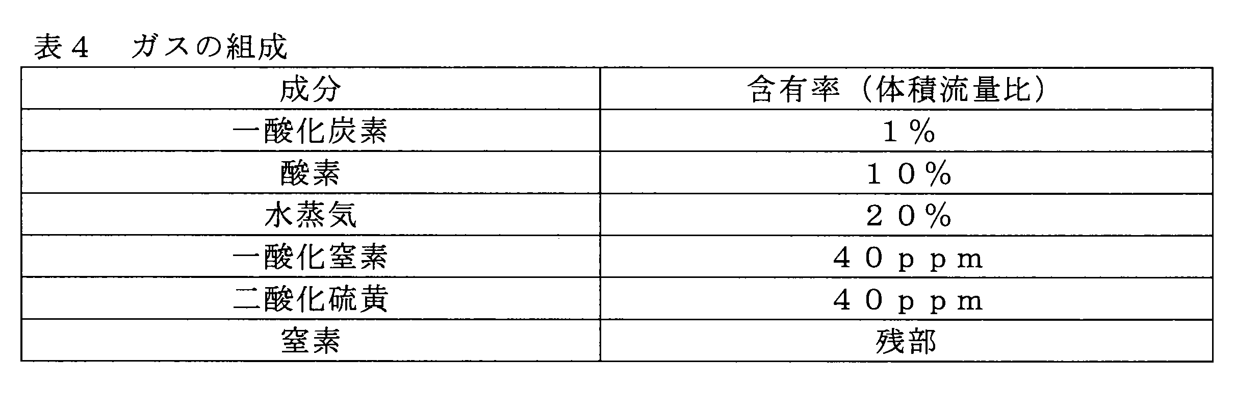
- the temperature was raised to 250 ° C. in a nitrogen stream at 100 cm 3 / min. After confirming that the temperature was stable, the reaction was performed by flowing a gas having the composition shown in Table 4 at a flow rate of 100 cm 3 / min.
- the space velocity indicating the relative ratio of gas and catalyst amount is approximately 600000 cm 3 ⁇ hour ⁇ 1 ⁇ catalyst mass (g) ⁇ 1 .
- Samples 1, 4, and 6 were subjected to a carbon monoxide oxidation reaction test.
- 10 mg of each of the three types of catalysts 20 mg of carriers 1, 2, and 4 were mixed and diluted, respectively, and filled into quartz glass tubes.
- the composition shown in Table 4 at a reaction temperature of 250 ° C. and a flow rate of 100 cm 3 / min was used for both the case where the reduction treatment was performed under a hydrogen stream at 500 ° C. and 60 cm 3 / min.
- the reaction was performed by flowing gas.
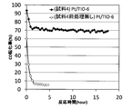
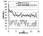
- the results are shown in FIGS. 9A to 9C.
- Sample 1 the same carbon monoxide conversion rate was obtained regardless of the presence or absence of the reduction treatment, but in Samples 4 and 6, the activity changed greatly depending on the presence or absence of the reduction treatment, and the reduction treatment was not performed. There is no activity.
- the titanium dioxide carrier used in Sample 1 is an anatase type structure carrier prepared by the sulfuric acid method, has a smaller amount of oxygen deficiency than the rutile type structure of Sample 5, and is difficult to oxidize the supported platinum. It is known that high activity is likely to occur even when there is no reduction treatment. Further, it is known that the anatase type structure prepared by the sulfuric acid method is less likely to cause a phase transition at a temperature of 500 ° C. or higher than the anatase type structure prepared by the chlorine method of Sample 6. For this reason, it is considered that the conversion rate of carbon monoxide in Sample 1 was the same as that obtained in the case of the reduction treatment even in the case of no reduction treatment.
- the denitration process shown in FIG. 1 was examined using each of the honeycomb-shaped catalysts 1, 2, and 3.
- a throw-in type electric heater was used instead of the gas heating burner 2, and a shell and tube type heat exchanger was used as the heat exchanging unit 1.
- a denitration reaction test was conducted with the entire apparatus kept warm.
- the combustion catalyst filled in the combustion catalyst portion 3 the honeycomb-shaped catalysts 1, 2, and 3 were used, and the filling amount was 1.2L.
- the denitration catalyst unit 4 was filled with 5 L of the lattice catalyst.
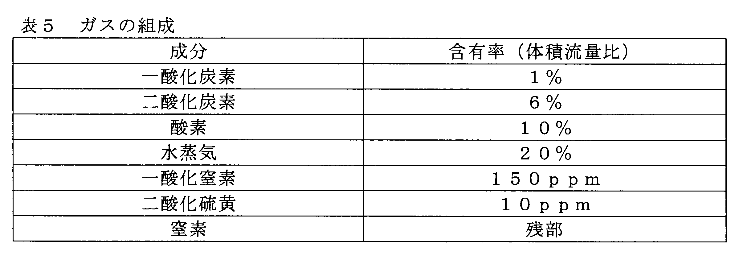
- As the composition of the exhaust gas a gas having the composition shown in Table 5 that simulates the sintering furnace exhaust gas of the steel manufacturing process was used.
- the honeycomb-shaped oxidation catalysts 1, 2, and 3 of the present invention are filled with 1.2 L and denitration catalyst with 1.6 L, and an exhaust gas at 60 ° C. having the composition shown in Table 5 is supplied from the inlet of the heat exchange section to 30 Nm 3 / hour (hour). It was made to flow in.
- the electric heater is turned on, and when the temperature at the inlet of the combustion catalyst reaches 200 ° C., ammonia is injected from the upstream of the denitration unit 4 so that the flow rate ratio to nitrogen monoxide is 0.9.
- the heater was turned off.
- a good denitration rate was maintained in all cases of the honeycomb catalysts 1, 2, and 3. The results are shown in Table 6.
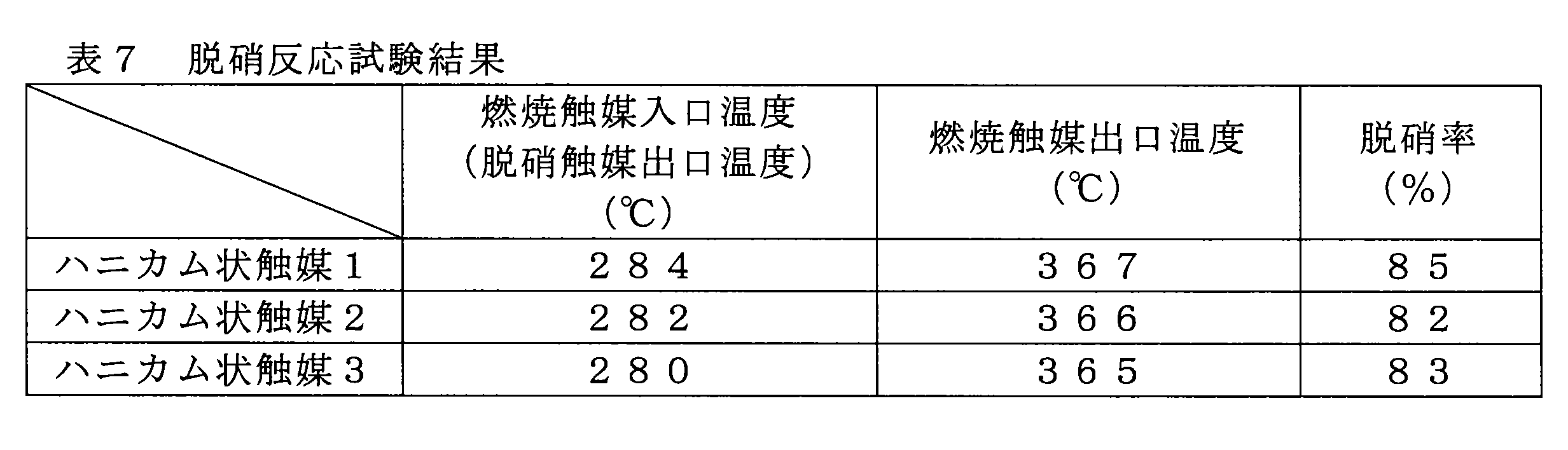
- the denitration process shown in FIG. 2 was examined using each of the above honeycomb-like catalysts 1, 2, and 3.
- a throwing type electric heater was used instead of the gas heating burner 12, and a shell and tube type heat exchanger was used for the heat exchanging portion 11.
- the denitration catalyst section 13 was filled with a 3.3 mm pitch titanium dioxide-based lattice catalyst, and a denitration reaction test was performed in a state where the entire apparatus was sufficiently kept warm.
- the combustion catalyst filled in the combustion catalyst section 14 the honeycomb-shaped catalysts 1, 2, and 3 were used, and the composition of the exhaust gas was a gas having the composition shown in Table 5 as in Test Example 6.
- the honeycomb-shaped catalysts 1, 2, and 3 were filled with 1.2 L and the denitration catalyst was filled with 1.6 L, and an exhaust gas at 60 ° C. having the composition shown in Table 5 was introduced at 30 Nm 3 / hour from the inlet of the heat exchange section. .
- the electric heater is turned on, and when the temperature at the inlet of the combustion catalyst section reaches 280 ° C., ammonia is injected from the upstream side of the denitration apparatus section 13 so that the flow rate ratio to nitrogen monoxide becomes 0.9.
- the heater was turned off.
- a good denitration rate was maintained in all cases of the honeycomb catalysts 1, 2, and 3. The results are shown in Table 7.
Landscapes
- Chemical & Material Sciences (AREA)
- Engineering & Computer Science (AREA)
- Chemical Kinetics & Catalysis (AREA)
- Organic Chemistry (AREA)
- Materials Engineering (AREA)
- Environmental & Geological Engineering (AREA)
- General Chemical & Material Sciences (AREA)
- Oil, Petroleum & Natural Gas (AREA)
- Biomedical Technology (AREA)
- Analytical Chemistry (AREA)
- Health & Medical Sciences (AREA)
- Catalysts (AREA)
- Nanotechnology (AREA)
- Exhaust Gas Treatment By Means Of Catalyst (AREA)
- Incineration Of Waste (AREA)
- Air Supply (AREA)
Abstract
Description
(1)担体に、白金、パラジウム、ロジウムからなる群から選ばれる遷移元素のうち少なくとも1種が担持された酸化触媒であり、前記酸化触媒における細孔半径2nm以上100nm以下の範囲の細孔において、当該範囲の細孔の全表面積に占める、細孔半径10nm以上の細孔で形成される表面積の割合が、49%超である、酸化触媒。
(2)担体に、白金、パラジウム、ロジウムからなる群から選ばれる遷移元素のうち少なくとも1種が担持された、ガス中の可燃成分を酸化する酸化触媒であって、前記酸化触媒における細孔半径2nm以上100nm以下の範囲の細孔において、当該範囲の細孔の全表面積に占める、細孔半径10nm以上の細孔で形成される表面積の割合が、49%超である、酸化触媒。
(3)前記範囲の細孔の全表面積に占める、細孔半径10nm以上の細孔で形成される表面積の割合が、60%以上である、(1)又は(2)に記載の酸化触媒。
(4)前記範囲の細孔の全表面積に占める、細孔半径20nm以上の細孔で形成される表面積の割合が、20%以上である、(1)~(3)の何れか1項に記載の酸化触媒。
(5)前記範囲の細孔の全表面積に占める、細孔半径20nm以上の細孔で形成される表面積の割合が、30%以上である、(1)~(4)の何れか1項に記載の酸化触媒。
(6)前記範囲の細孔の全表面積に占める、細孔半径80nm以上の細孔で形成される表面積の割合が、2%以上である、(1)~(5)の何れか1項に記載の酸化触媒。
(7)比表面積が20m2/g以下である、(1)~(6)の何れか1項に記載の酸化触媒。
(8)前記酸化触媒に担持される前記遷移金属が、白金である、(1)~(7)の何れか1項に記載の酸化触媒。
(9)前記酸化触媒に担持される前記遷移元素の比率が、当該遷移元素の金属換算の質量比の和として、前記酸化触媒の全質量に対して、0.01%以上2.0%以下である、(1)~(8)の何れか1項に記載の酸化触媒。
(10)前記酸化触媒の担体が、融点1300℃以上の酸化物担体である、(1)~(9)の何れか1項に記載の酸化触媒。
(11)前記酸化触媒の担体が、二酸化チタン、又は、酸化ジルコニウムの何れかである、(1)~(10)の何れか1項に記載の酸化触媒。
(12)前記酸化触媒の担体が、アナターゼ型構造の二酸化チタンである、(11)に記載の酸化触媒。
(13)前記二酸化チタンは、硫酸法にて製造された二酸化チタンである、(11)又は(12)に記載の酸化触媒。
(14)触媒を利用して被処理ガス中に含まれる未燃成分を燃焼させる燃焼触媒部を備え、前記燃焼触媒部に、(1)~(13)の何れか1項に記載の酸化触媒が充填されている、排ガス処理装置。
(15)前記燃焼触媒部の前段に設けられ、前記被処理ガスの温度を上昇させるガス加熱部と、前記燃焼触媒部の後段に設けられ、前記被処理ガス中の窒素酸化物を除去する脱硝部と、を更に備える、(14)に記載の排ガス処理装置。
(16)前記燃焼触媒部の前段に設けられ、前記被処理ガス中の窒素酸化物を除去する脱硝部と、前記脱硝部の前段に設けられ、前記被処理ガスの温度を上昇させるガス加熱部と、
を更に備え、前記燃焼触媒部で発生した燃焼熱が、前記ガス加熱部に供給される前記被処理ガスの加熱に用いられる、(14)に記載の排ガス処理装置。
(17)燃料及び燃焼空気の混合気を噴射する混合気噴射部と、蓄熱体が配置されており、被処理ガスを流通させて顕熱を蓄熱体に蓄熱し、蓄熱後に燃焼空気を流通させて、蓄熱した熱量で当該燃焼空気を加熱する蓄熱部と、を備え、前記蓄熱部と前記混合気噴射部との間に設けられた燃焼触媒部、又は、前記蓄熱部には、(1)~(13)の何れか1項に記載の酸化触媒が充填されている、蓄熱燃焼バーナー。
(18)(1)~(13)のいずれか1項に記載の酸化触媒を用いて、水蒸気及び硫黄酸化物を含む被処理ガス中の一酸化炭素、一酸化窒素、メタンからなる群から選ばれる可燃成分を酸化する、ガス中の可燃成分を酸化する方法。
(19)前記被処理ガスと前記酸化触媒の接触する温度が、250℃以上300℃未満である、(18)に記載のガス中の可燃成分を酸化する方法。
(20)被処理ガスの温度を上昇させるガス加熱部と、被処理ガス中の窒素酸化物を除去する脱硝部と、を有するガス処理プロセスを用い、窒素酸化物を含むと共に、水蒸気と硫黄酸化物と可燃性ガスとを含む被処理ガス中の窒素酸化物を除去する方法であって、前記ガス加熱部と前記脱硝部との間に、(1)~(13)の何れか1項に記載の酸化触媒が充填された燃焼触媒部を配置し、当該燃焼触媒部に前記ガス加熱部で加熱された前記被処理ガスを通過させて、前記被処理ガス中の可燃成分を燃焼し、その燃焼熱により前記被処理ガスの温度を更に上昇させる、ガス中の窒素酸化物の除去方法。
(21)前記ガス加熱部として、熱交換器と、ガス加熱バーナー又は電熱ヒーターとを用い、前記脱硝部から排出されたガスを、前記熱交換器の高温ガスとして使用する、(20)に記載のガス中の窒素酸化物の除去方法。
(22)前記ガス加熱部として、熱交換器と、ガス加熱バーナー又は電熱ヒーターとを用い、前記燃焼触媒部の位置を、前記ガス加熱部と前記脱硝部の間から、前記ガス加熱部及び前記脱硝部の後段に配置換えし、前記燃焼触媒部から排出されたガスを、前記熱交換器の高温ガスとして使用する、(20)に記載のガス中の窒素酸化物の除去方法。
(23)前記被処理ガスが、鉄鋼製造プロセスにおける焼結炉の排ガスである、(20)~(22)の何れか1項に記載のガス中の窒素酸化物の除去方法。
焼結炉からの排ガスやバーナーからの排ガスに代表される工場排ガス中には、二酸化硫黄、三酸化硫黄に代表される硫黄酸化物に加え、多量の水蒸気が含まれている。酸化触媒を用いて、これらの排ガスに含まれる可燃物質を燃焼させる際には、二酸化硫黄が酸化されて三酸化硫黄の量が増大し、濃硫酸が生成する。三酸化硫黄及び濃硫酸は、多くの酸化物と容易に反応し、硫酸化物となることが知られており、この反応により触媒の活性が大きく損なわれることが知られている。
P:蒸気圧 P0:飽和蒸気圧 γ:表面張力[N/m]
Vm:モル体積[m3/mol] r:液滴半径[m]
R:気体定数[J/mol・K] T:絶対温度[K] θ:接触角[rad]
以上の検討を踏まえ、細孔半径の大きい細孔の比率が高い担体を用いることで、細孔内部での濃硫酸の閉塞を抑制出来ると考えられた。つまり、上記第一の要因については、細孔半径が大きくなることで液体の凝縮に要する蒸気圧が大きくなり、細孔の閉塞が生じ難くなると考えられた。上記第二の要因については、平均自由工程に対して細孔半径が大きくなるにつれて、気相中を運動する分子同士の衝突の影響が現れ、壁面との衝突による影響が小さくなる。その結果、細孔内での三酸化硫黄の拡散が生じ易くなり、第二の要因に関しても細孔の閉塞が生じ難くなると考えられた。
(担体1~11)
酸化チタン担体TIO-2(触媒学会参照触媒)、酸化チタン担体TIO-6(触媒学会参照触媒)、酸化ジルコニウム担体ZRO-4(触媒学会参照触媒)、酸化チタン担体TIO-4(触媒学会参照触媒)、酸化チタン担体TIO-8(触媒学会参照触媒)、酸化チタン担体TIO-7(触媒学会参照触媒)、酸化チタン担体ST-01(石原産業)、酸化チタン担体FTL-110(石原産業)、酸化チタン担体FTL-200(石原産業)、酸化ジルコニウム担体ZRO-3(触媒学会参照触媒)、酸化アルミニウム担体ALO-1(触媒学会参照触媒)を用意し、それぞれを大気雰囲気下500℃にて1時間焼成した。得られた担体を、それぞれ担体1~11とした。

(実施例1:白金担持触媒)
ヘキサクロロ白金酸0.00265gを、0.20ml、0.45ml、0.20ml、0.35mlの純水それぞれに溶解させた。得られた白金前駆体溶液を、担体1~5の酸化物担体各1.00gに対して十分な混合を行いながらそれぞれ滴下し、含浸させた。得られた粉末を、100℃にて10時間、500℃にて1時間焼成し、得られた触媒を試料1、4~7とした。白金の担持量はいずれも、金属状態の白金換算で0.1質量%であった。
ジニトロジアンミンパラジウム(小島化学薬品)0.00220gを硝酸15mlに溶解し、担体1の酸化物担体1.00gを加えた。1時間攪拌を行った後に、ホットスターラー上80℃にて攪拌を行い、蒸発乾固した。得られた固体を、大気下120℃にて10時間乾燥させた後に400℃まで昇温し30分焼成した。冷却後得られた触媒を、試料2とした。試料2について、実施例1の場合と同様に測定した物性値を、表2に示す。
塩化ロジウム(III)三水和物0.00256を、0.20mlの純水に溶解させた。得られたロジウム前駆体水溶液を、担体1の酸化物担体1.00gに対して、十分な混合を行いながらそれぞれ滴下し、含浸させた。得られた粉末を、100℃にて10時間、500℃にて1時間焼成し、得られた触媒を試料3とした。ロジウムの担持量は、金属状態のロジウム換算で0.1質量%であった。試料3について、実施例1の場合と同様に測定した物性値を、表2に示す。
ヘキサクロロ白金酸0.00265gを、1.0mlの純水に溶解させた。得られた白金前駆体溶液のうち0.30mlを、担体1の酸化物担体各1.00gに対して十分な混合を行いながら滴下し、含浸させた。得られた粉末を、100℃にて10時間、500℃にて1時間焼成し、得られた触媒を試料8とした。白金の担持量は、金属状態の白金換算で0.03質量%であった。試料8について、実施例1の場合と同様に測定した物性値を表2に示す。
ヘキサクロロ白金酸0.02589g、0.05178を、それぞれ0.45mlの純水に溶解させた。得られた白金前駆体溶液をそれぞれ、担体2の酸化物担体1.00gに対して十分な混合を行いながらそれぞれ滴下し、含浸させた。得られた粉末を、100℃にて10時間、500℃にて1時間焼成し、得られた触媒をそれぞれ試料9、10とした。白金の担持量はそれぞれ、金属状態の白金換算で1質量%、2質量%であった。試料9、10について、実施例1の場合と同様に測定した物性値を表2に示す。
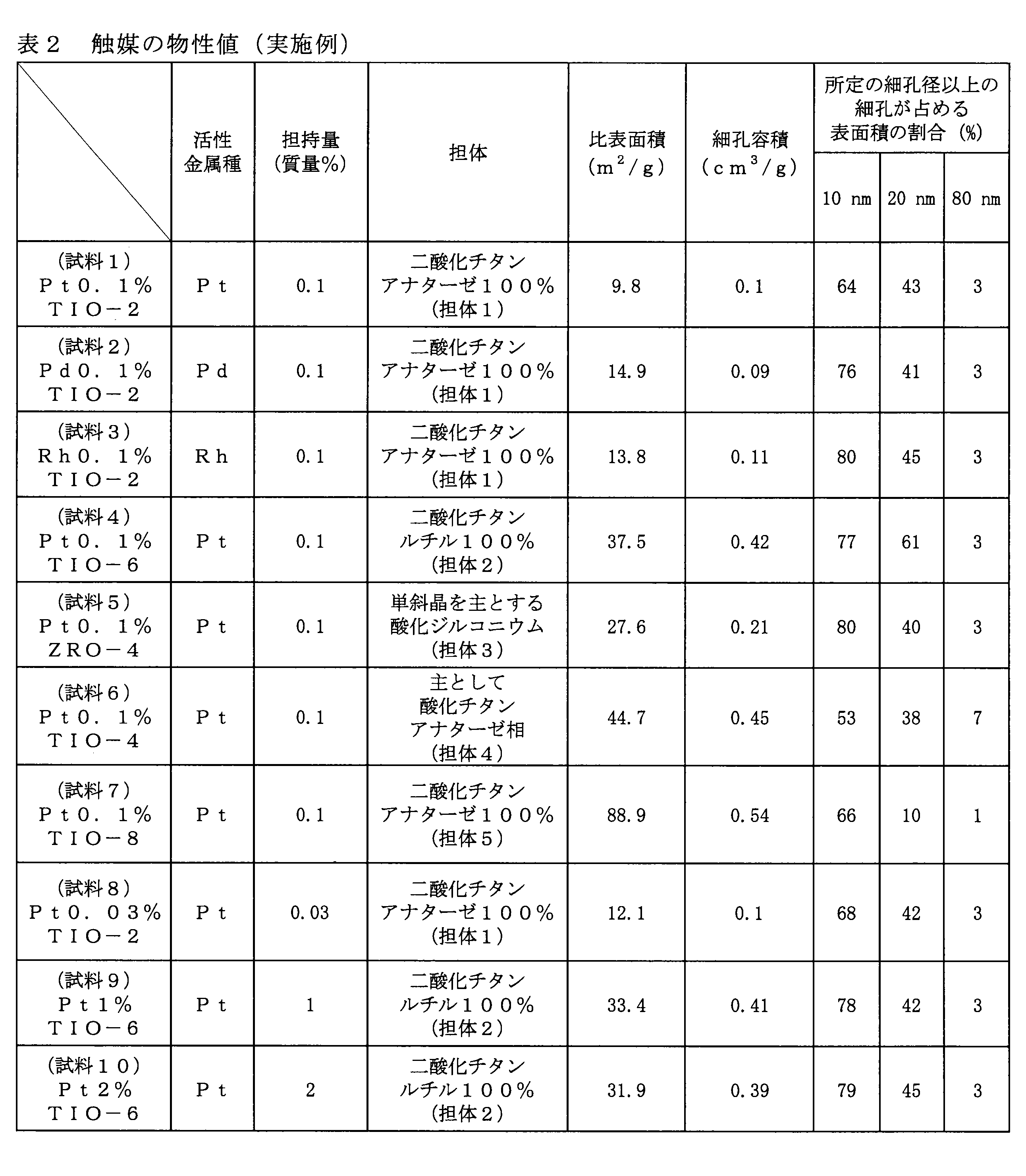
ヘキサクロロ白金酸0.00265gを、表1に示す担体6~11の細孔容積と同量の純水に溶解させた。得られた白金前駆体溶液を、それぞれ担体6~11の酸化物担体各1.00gに対して十分な混合を行いながらそれぞれ滴下し、各担体に含浸させた。得られた粉末を、100℃にて10時間、500℃にて1時間焼成し、得られた触媒を試料A~Fとした。白金の担持量はいずれも、金属状態の白金換算で0.1質量%であった。
ジニトロジアンミンパラジウム(小島化学薬品)0.00220gを硝酸15mlに溶解し、担体6の酸化物担体1.00gを加えた。1時間攪拌を行った後に、ホットスターラー上80℃にて攪拌を行い、蒸発乾固した。得られた固体を、大気下120℃にて10時間乾燥させた後に、400℃まで昇温し30分焼成した。冷却後得られた触媒を試料Gとした。試料Gについて、実施例1の場合と同様に測定した物性値を表3に示す。
塩化ロジウム(III)三水和物0.00256を0.20mlの純水に溶解させた。得られたロジウム前駆体水溶液を、担体6の酸化物担体1.00gに対して、十分な混合を行いながらそれぞれ滴下し、含浸させた。得られた粉末を、100℃にて10時間、500℃にて1時間焼成し、得られた触媒を試料Hとした。ロジウムの担持量は、金属状態のロジウム換算で0.1質量%である。試料Hについて、実施例1の場合と同様に測定した物性値を表3に示す。
(試験例1:還元前処理後加速試験)
試料1、4~10及び、試料A~Fについて一酸化炭素酸化反応試験を行った。
先ず、試料1、4~7、9、10、A~Fの各触媒10mgそれぞれに対して、20mgの担体1、2、3、4、5、2、2、6、7、8、9、10、11をそれぞれ混合して希釈し、それぞれ石英ガラス管に充填した。貴金属担持量の少ない試料8については、33mg秤量し、希釈せずに石英ガラス管に充填した。
次に、60cm3/分の水素気流中、500℃にて1時間還元処理を行った後に250℃まで降温した。100cm3/分の窒素気流中にて10分間パージを行った後に、反応温度250℃、大気圧で流量100cm3/分にて表4に示す組成のガスを流して反応を行った。
試料9、10については図6A~図6Dに記載していないが、両者共に反応開始から終了時まで、一酸化炭素転化率は、100%で推移した。発明例の試料1、4~10と比較例の試料A~Fでは、その一酸化炭素の転化率の時間依存性に大きな違いがあり、試料1、4~10では反応時間15時間経過時点においても高い活性が得られているものの、試料A~Fでは15時間経過時点において活性が大きく低下していることが分る。
発明例である試料1、4及び比較例である試料Bについて、一酸化炭素酸化活性の温度依存性を調べた。
試料Bについて、試験例1と同様の測定を行った。その後に、表4に示すガス組成から、二酸化硫黄を20ppmに、又は、水蒸気量を10%にしたそれぞれの場合にて、測定を行った。その結果、それぞれ一酸化炭素転化率は9.4%、7.4%であり、ガス組成を変える前の8.4%と大きく差の無い値となった。このことより、試料Bで見られた濃硫酸による細孔の閉塞は、二酸化硫黄と水蒸気の濃度が異なっていても生じるものと考えられる。
試料1~3、試料G、Hについて、一酸化炭素酸化反応試験を行った。試料1~3の各触媒10mgそれぞれに対して、20mgの担体1をそれぞれ混合して希釈し、それぞれ石英ガラス管に充填した。また、試料G、Hの各触媒10mgそれぞれに対して、20mgの担体5をそれぞれ混合して希釈し、それぞれ石英ガラス管に充填した。100cm3/分の窒素気流中にて250℃まで昇温した。温度が安定したことを確認した上で、流量100cm3/分で表4に示す組成のガスを流して反応を行った。ガスと触媒量の相対比を示す空間速度は、大凡600000cm3・時間(hour)-1・触媒質量(g)-1である。
試料1、4、6について一酸化炭素酸化反応試験を行った。3種類の各触媒10mgそれぞれに対して、20mgの担体1、2、4をそれぞれ混合して希釈し、それぞれ石英ガラス管に充填した。反応開始前に、500℃、60cm3/分の水素気流下での還元処理を行ったものと、行わなかったものの双方について、反応温度250℃、流量100cm3/分で表4に示す組成のガスを流して反応を行った。
試料1、2、5の粉末それぞれを、4.2mmピッチ(壁厚0.5mm)のコージェライト製ハニカム素材に対し、基材表面積当り200g/m2でコートし、ハニカム状触媒1、2、3を得た。脱硝触媒には、3.3mmピッチのコージェライト製ハニカムに対し、二酸化チタン系脱硝触媒を基材表面積当り200g/m2でコートした格子状触媒を用いた。

試料1、2、5の粉末それぞれを、4.2mmピッチ(壁厚0.5mm)のコージェライト製ハニカム素材に対し、基材表面積当り200g/m2でコートし、ハニカム状触媒1、2、3を得た。
2 ガス加熱バーナー
3 燃焼触媒部
4 脱硝装置部
11 熱交換部
12 ガス加熱バーナー
13 脱硝装置部
14 燃焼触媒部
21 排気空気流路切替器
22a,22b 蓄熱部
23a,23b 燃料ガス供給部
24a,24b 混合気噴射部
25 空間
26 空気導入経路
27 排ガス経路
28a,28b 二次空気導入経路
Claims (23)
- 担体に、白金、パラジウム、ロジウムからなる群から選ばれる遷移元素のうち少なくとも1種が担持された酸化触媒であり、
前記酸化触媒における細孔半径2nm以上100nm以下の範囲の細孔において、当該範囲の細孔の全表面積に占める、細孔半径10nm以上の細孔で形成される表面積の割合が、49%超である、酸化触媒。 - 担体に、白金、パラジウム、ロジウムからなる群から選ばれる遷移元素のうち少なくとも1種が担持された、ガス中の可燃成分を酸化する酸化触媒であって、
前記酸化触媒における細孔半径2nm以上100nm以下の範囲の細孔において、当該範囲の細孔の全表面積に占める、細孔半径10nm以上の細孔で形成される表面積の割合が、49%超である、酸化触媒。 - 前記範囲の細孔の全表面積に占める、細孔半径10nm以上の細孔で形成される表面積の割合が、60%以上である、請求項1又は2に記載の酸化触媒。
- 前記範囲の細孔の全表面積に占める、細孔半径20nm以上の細孔で形成される表面積の割合が、20%以上である、請求項1~3の何れか1項に記載の酸化触媒。
- 前記範囲の細孔の全表面積に占める、細孔半径20nm以上の細孔で形成される表面積の割合が、30%以上である、請求項1~4の何れか1項に記載の酸化触媒。
- 前記範囲の細孔の全表面積に占める、細孔半径80nm以上の細孔で形成される表面積の割合が、2%以上である、請求項1~5の何れか1項に記載の酸化触媒。
- 比表面積が20m2/g以下である、請求項1~6の何れか1項に記載の酸化触媒。
- 前記酸化触媒に担持される前記遷移金属が、白金である、請求項1~7の何れか1項に記載の酸化触媒。
- 前記酸化触媒に担持される前記遷移元素の比率が、当該遷移元素の金属換算の質量比の和として、前記酸化触媒の全質量に対して、0.01%以上2.0%以下である、請求項1~8の何れか1項に記載の酸化触媒。
- 前記酸化触媒の担体が、融点1300℃以上の酸化物担体である、請求項1~9の何れか1項に記載の酸化触媒。
- 前記酸化触媒の担体が、二酸化チタン、又は、酸化ジルコニウムの何れかである、請求項1~10の何れか1項に記載の酸化触媒。
- 前記酸化触媒の担体が、アナターゼ型構造の二酸化チタンである、請求項11に記載の酸化触媒。
- 前記二酸化チタンは、硫酸法にて製造された二酸化チタンである、請求項11又は12に記載の酸化触媒。
- 触媒を利用して被処理ガス中に含まれる未燃成分を燃焼させる燃焼触媒部を備え、
前記燃焼触媒部に、請求項1~13の何れか1項に記載の酸化触媒が充填されている、排ガス処理装置。 - 前記燃焼触媒部の前段に設けられ、前記被処理ガスの温度を上昇させるガス加熱部と、
前記燃焼触媒部の後段に設けられ、前記被処理ガス中の窒素酸化物を除去する脱硝部と、
を更に備える、請求項14に記載の排ガス処理装置。 - 前記燃焼触媒部の前段に設けられ、前記被処理ガス中の窒素酸化物を除去する脱硝部と、
前記脱硝部の前段に設けられ、前記被処理ガスの温度を上昇させるガス加熱部と、
を更に備え、
前記燃焼触媒部で発生した燃焼熱が、前記ガス加熱部に供給される前記被処理ガスの加熱に用いられる、請求項14に記載の排ガス処理装置。 - 燃料及び燃焼空気の混合気を噴射する混合気噴射部と、
蓄熱体が配置されており、被処理ガスを流通させて顕熱を蓄熱体に蓄熱し、蓄熱後に燃焼空気を流通させて、蓄熱した熱量で当該燃焼空気を加熱する蓄熱部と、
を備え、
前記蓄熱部と前記混合気噴射部との間に設けられた燃焼触媒部、又は、前記蓄熱部には、請求項1~13の何れか1項に記載の酸化触媒が充填されている、蓄熱燃焼バーナー。 - 請求項1~13のいずれか1項に記載の酸化触媒を用いて、水蒸気及び硫黄酸化物を含む被処理ガス中の一酸化炭素、一酸化窒素、メタンからなる群から選ばれる可燃成分を酸化する、ガス中の可燃成分を酸化する方法。
- 前記被処理ガスと前記酸化触媒の接触する温度が、250℃以上300℃未満である、請求項18に記載のガス中の可燃成分を酸化する方法。
- 被処理ガスの温度を上昇させるガス加熱部と、被処理ガス中の窒素酸化物を除去する脱硝部と、を有するガス処理プロセスを用い、窒素酸化物を含むと共に、水蒸気と硫黄酸化物と可燃性ガスとを含む被処理ガス中の窒素酸化物を除去する方法であって、
前記ガス加熱部と前記脱硝部との間に、請求項1~13の何れか1項に記載の酸化触媒が充填された燃焼触媒部を配置し、
当該燃焼触媒部に前記ガス加熱部で加熱された前記被処理ガスを通過させて、前記被処理ガス中の可燃成分を燃焼し、その燃焼熱により前記被処理ガスの温度を更に上昇させる、ガス中の窒素酸化物の除去方法。 - 前記ガス加熱部として、熱交換器と、ガス加熱バーナー又は電熱ヒーターとを用い、
前記脱硝部から排出されたガスを、前記熱交換器の高温ガスとして使用する、請求項20に記載のガス中の窒素酸化物の除去方法。 - 前記ガス加熱部として、熱交換器と、ガス加熱バーナー又は電熱ヒーターとを用い、
前記燃焼触媒部の位置を、前記ガス加熱部と前記脱硝部の間から、前記ガス加熱部及び前記脱硝部の後段に配置換えし、
前記燃焼触媒部から排出されたガスを、前記熱交換器の高温ガスとして使用する、請求項20に記載のガス中の窒素酸化物の除去方法。 - 前記被処理ガスが、鉄鋼製造プロセスにおける焼結炉の排ガスである、請求項20~22の何れか1項に記載のガス中の窒素酸化物の除去方法。
Priority Applications (3)
| Application Number | Priority Date | Filing Date | Title |
|---|---|---|---|
| CN201480050004.9A CN105531026B (zh) | 2013-09-10 | 2014-09-05 | 氧化催化剂、废气处理装置、蓄热燃烧器、气体中的可燃成分的氧化方法和气体中的氮氧化物的去除方法 |
| KR1020157034663A KR101814893B1 (ko) | 2013-09-10 | 2014-09-05 | 산화 촉매, 배기 가스 처리 장치, 축열 연소 버너, 가스 중의 가연 성분을 산화하는 방법 및 가스 중의 질소산화물의 제거 방법 |
| JP2015536562A JP6103067B2 (ja) | 2013-09-10 | 2014-09-05 | 酸化触媒、排ガス処理装置、蓄熱燃焼バーナー、ガス中の可燃成分を酸化する方法及びガス中の窒素酸化物の除去方法 |
Applications Claiming Priority (2)
| Application Number | Priority Date | Filing Date | Title |
|---|---|---|---|
| JP2013-187107 | 2013-09-10 | ||
| JP2013187107 | 2013-09-10 |
Publications (1)
| Publication Number | Publication Date |
|---|---|
| WO2015037536A1 true WO2015037536A1 (ja) | 2015-03-19 |
Family
ID=52665642
Family Applications (1)
| Application Number | Title | Priority Date | Filing Date |
|---|---|---|---|
| PCT/JP2014/073516 Ceased WO2015037536A1 (ja) | 2013-09-10 | 2014-09-05 | 酸化触媒、排ガス処理装置、蓄熱燃焼バーナー、ガス中の可燃成分を酸化する方法及びガス中の窒素酸化物の除去方法 |
Country Status (5)
| Country | Link |
|---|---|
| JP (1) | JP6103067B2 (ja) |
| KR (1) | KR101814893B1 (ja) |
| CN (1) | CN105531026B (ja) |
| TW (1) | TWI600467B (ja) |
| WO (1) | WO2015037536A1 (ja) |
Cited By (10)
| Publication number | Priority date | Publication date | Assignee | Title |
|---|---|---|---|---|
| JP2015211960A (ja) * | 2014-04-16 | 2015-11-26 | 新日鐵住金株式会社 | 被処理ガス中の可燃成分の酸化触媒、被処理ガス中の可燃成分の酸化触媒の製造方法、被処理ガス中の可燃成分の酸化方法、及び、被処理ガス中の窒素酸化物の除去方法 |
| JP2017018922A (ja) * | 2015-07-14 | 2017-01-26 | 新日鐵住金株式会社 | 酸化触媒 |
| JP2017064627A (ja) * | 2015-09-30 | 2017-04-06 | 日揮触媒化成株式会社 | 排ガス処理用触媒およびその製造方法 |
| JP2017080678A (ja) * | 2015-10-28 | 2017-05-18 | 新日鐵住金株式会社 | 排ガス中の未燃成分の除去方法及び排ガス中の窒素酸化物の除去方法 |
| JP2018094520A (ja) * | 2016-12-15 | 2018-06-21 | 三菱日立パワーシステムズ株式会社 | 燃焼排ガスからNOxを除去するための触媒および方法 |
| WO2018164193A1 (ja) * | 2017-03-08 | 2018-09-13 | 三菱ケミカル株式会社 | カルボニル化合物の水素化触媒ならびにアルコールの製造方法 |
| WO2019054071A1 (ja) * | 2017-09-12 | 2019-03-21 | 三菱日立パワーシステムズ株式会社 | Co酸化触媒及びその製造方法 |
| WO2020039903A1 (ja) * | 2018-08-22 | 2020-02-27 | 三井金属鉱業株式会社 | 排ガス浄化触媒用多孔質構造体及びそれを用いた排ガス浄化触媒並びに排ガス浄化方法 |
| CN113790445A (zh) * | 2021-08-16 | 2021-12-14 | 昆明理工大学 | 一种天然气催化燃烧蓄热型红外加热物体的方法 |
| US12415158B2 (en) | 2020-07-07 | 2025-09-16 | Daphne Technology SA | Apparatus and method for electron irradiation scrubbing |
Families Citing this family (3)
| Publication number | Priority date | Publication date | Assignee | Title |
|---|---|---|---|---|
| JP7211709B2 (ja) * | 2018-02-27 | 2023-01-24 | エヌ・イーケムキャット株式会社 | 排ガス浄化用三元触媒及びその製造方法、並びに一体構造型排ガス浄化用触媒 |
| CN110038558B (zh) * | 2019-04-09 | 2022-09-27 | 中国船舶重工集团公司第七一八研究所 | 一种低贵金属含量高活性催化剂的制备方法及其应用 |
| US20230264178A1 (en) * | 2022-02-23 | 2023-08-24 | Robert Bosch Gmbh | Propane gas removal material |
Citations (10)
| Publication number | Priority date | Publication date | Assignee | Title |
|---|---|---|---|---|
| JPH05115750A (ja) * | 1991-10-28 | 1993-05-14 | Kawasaki Steel Corp | 焼結炉排ガス中の一酸化炭素の酸化制御方法 |
| JPH06171915A (ja) * | 1992-08-12 | 1994-06-21 | Corning Inc | 細孔径を調整したリン酸塩−アルミナ材料 |
| JPH09117674A (ja) * | 1995-09-12 | 1997-05-06 | Basf Ag | 単一モード又は多モードの触媒担体又は触媒、その製造方法及び塩素の製造方法 |
| JPH11104493A (ja) * | 1997-10-02 | 1999-04-20 | Nissan Motor Co Ltd | 排気ガス浄化用触媒及び使用方法 |
| JPH11169728A (ja) * | 1997-12-15 | 1999-06-29 | Toho Gas Co Ltd | メタン酸化触媒 |
| JP2000300961A (ja) * | 1999-04-20 | 2000-10-31 | Mitsubishi Heavy Ind Ltd | 排ガス脱硝方法及び装置 |
| JP2001336733A (ja) * | 2000-05-26 | 2001-12-07 | Mitsubishi Kakoki Kaisha Ltd | 蓄熱燃焼バ−ナ |
| JP2005270821A (ja) * | 2004-03-25 | 2005-10-06 | Mitsubishi Heavy Ind Ltd | 一酸化炭素燃焼触媒およびその製造方法 |
| JP2010227931A (ja) * | 2009-03-06 | 2010-10-14 | Ict:Kk | 排気ガス浄化用触媒及びその製造方法、並びに排気ガス浄化方法 |
| JP2012011308A (ja) * | 2010-06-30 | 2012-01-19 | Jgc Catalysts & Chemicals Ltd | 排ガス浄化触媒及び排ガス浄化触媒の製造方法 |
Family Cites Families (12)
| Publication number | Priority date | Publication date | Assignee | Title |
|---|---|---|---|---|
| JPS51104488A (en) * | 1975-03-13 | 1976-09-16 | Toyota Motor Co Ltd | Shokubaitantai oyobi shokubai |
| JPS5535178A (en) | 1978-09-05 | 1980-03-12 | Toyota Motor Corp | Exhaust gas recirculating apparatus for internal combustion engine |
| JPS61161143A (ja) | 1984-12-29 | 1986-07-21 | Kawasaki Steel Corp | 排ガス中一酸化炭素酸化触媒および排ガス中の一酸化炭素酸化方法 |
| JP4411740B2 (ja) * | 2000-04-21 | 2010-02-10 | 三菱瓦斯化学株式会社 | 担持触媒及びその製造方法 |
| JP3742290B2 (ja) | 2000-09-08 | 2006-02-01 | 株式会社日本触媒 | 排水処理用触媒および該触媒を用いた排水の処理方法 |
| JP2007000697A (ja) * | 2005-06-21 | 2007-01-11 | Nissan Motor Co Ltd | 排ガス浄化触媒 |
| JP5165204B2 (ja) * | 2006-03-09 | 2013-03-21 | 国立大学法人大阪大学 | パラジウム微粒子の製造方法 |
| JP2008036602A (ja) * | 2006-08-10 | 2008-02-21 | Osaka Univ | 酸化反応用触媒、その製造方法およびそれを用いたp−キシリレンジアセテートの製造方法 |
| JP5447766B2 (ja) * | 2008-07-06 | 2014-03-19 | 独立行政法人産業技術総合研究所 | 金属ナノ粒子担持無機酸化物触媒による環境調和型酸素酸化法 |
| US8211392B2 (en) * | 2009-01-16 | 2012-07-03 | Basf Corporation | Diesel oxidation catalyst composite with layer structure for carbon monoxide and hydrocarbon conversion |
| EP2606971B1 (en) * | 2010-08-20 | 2017-03-29 | Mitsui Mining and Smelting Co., Ltd. | Oxidation catalyst suitable for combustion of light oil component |
| JP5788298B2 (ja) | 2011-11-22 | 2015-09-30 | 株式会社豊田中央研究所 | 排ガス浄化用触媒担体、それを用いた排ガス浄化用触媒、及びそれらの製造方法 |
-
2014
- 2014-09-05 KR KR1020157034663A patent/KR101814893B1/ko active Active
- 2014-09-05 CN CN201480050004.9A patent/CN105531026B/zh active Active
- 2014-09-05 WO PCT/JP2014/073516 patent/WO2015037536A1/ja not_active Ceased
- 2014-09-05 JP JP2015536562A patent/JP6103067B2/ja active Active
- 2014-09-09 TW TW103131018A patent/TWI600467B/zh active
Patent Citations (10)
| Publication number | Priority date | Publication date | Assignee | Title |
|---|---|---|---|---|
| JPH05115750A (ja) * | 1991-10-28 | 1993-05-14 | Kawasaki Steel Corp | 焼結炉排ガス中の一酸化炭素の酸化制御方法 |
| JPH06171915A (ja) * | 1992-08-12 | 1994-06-21 | Corning Inc | 細孔径を調整したリン酸塩−アルミナ材料 |
| JPH09117674A (ja) * | 1995-09-12 | 1997-05-06 | Basf Ag | 単一モード又は多モードの触媒担体又は触媒、その製造方法及び塩素の製造方法 |
| JPH11104493A (ja) * | 1997-10-02 | 1999-04-20 | Nissan Motor Co Ltd | 排気ガス浄化用触媒及び使用方法 |
| JPH11169728A (ja) * | 1997-12-15 | 1999-06-29 | Toho Gas Co Ltd | メタン酸化触媒 |
| JP2000300961A (ja) * | 1999-04-20 | 2000-10-31 | Mitsubishi Heavy Ind Ltd | 排ガス脱硝方法及び装置 |
| JP2001336733A (ja) * | 2000-05-26 | 2001-12-07 | Mitsubishi Kakoki Kaisha Ltd | 蓄熱燃焼バ−ナ |
| JP2005270821A (ja) * | 2004-03-25 | 2005-10-06 | Mitsubishi Heavy Ind Ltd | 一酸化炭素燃焼触媒およびその製造方法 |
| JP2010227931A (ja) * | 2009-03-06 | 2010-10-14 | Ict:Kk | 排気ガス浄化用触媒及びその製造方法、並びに排気ガス浄化方法 |
| JP2012011308A (ja) * | 2010-06-30 | 2012-01-19 | Jgc Catalysts & Chemicals Ltd | 排ガス浄化触媒及び排ガス浄化触媒の製造方法 |
Cited By (16)
| Publication number | Priority date | Publication date | Assignee | Title |
|---|---|---|---|---|
| JP2015211960A (ja) * | 2014-04-16 | 2015-11-26 | 新日鐵住金株式会社 | 被処理ガス中の可燃成分の酸化触媒、被処理ガス中の可燃成分の酸化触媒の製造方法、被処理ガス中の可燃成分の酸化方法、及び、被処理ガス中の窒素酸化物の除去方法 |
| JP2017018922A (ja) * | 2015-07-14 | 2017-01-26 | 新日鐵住金株式会社 | 酸化触媒 |
| JP2017064627A (ja) * | 2015-09-30 | 2017-04-06 | 日揮触媒化成株式会社 | 排ガス処理用触媒およびその製造方法 |
| JP2017080678A (ja) * | 2015-10-28 | 2017-05-18 | 新日鐵住金株式会社 | 排ガス中の未燃成分の除去方法及び排ガス中の窒素酸化物の除去方法 |
| JP2018094520A (ja) * | 2016-12-15 | 2018-06-21 | 三菱日立パワーシステムズ株式会社 | 燃焼排ガスからNOxを除去するための触媒および方法 |
| US11352309B2 (en) | 2017-03-08 | 2022-06-07 | Mitsubishi Chemical Corporation | Catalyst for hydrogenation of carbonyl compound and alcohol production method |
| WO2018164193A1 (ja) * | 2017-03-08 | 2018-09-13 | 三菱ケミカル株式会社 | カルボニル化合物の水素化触媒ならびにアルコールの製造方法 |
| JPWO2018164193A1 (ja) * | 2017-03-08 | 2020-01-09 | 三菱ケミカル株式会社 | カルボニル化合物の水素化触媒ならびにアルコールの製造方法 |
| JP7111093B2 (ja) | 2017-03-08 | 2022-08-02 | 三菱ケミカル株式会社 | カルボニル化合物の水素化触媒ならびにアルコールの製造方法 |
| US11014862B2 (en) | 2017-03-08 | 2021-05-25 | Mitsubishi Chemical Corporation | Catalyst for hydrogenation of carbonyl compound and alcohol production method |
| WO2019054071A1 (ja) * | 2017-09-12 | 2019-03-21 | 三菱日立パワーシステムズ株式会社 | Co酸化触媒及びその製造方法 |
| WO2020039903A1 (ja) * | 2018-08-22 | 2020-02-27 | 三井金属鉱業株式会社 | 排ガス浄化触媒用多孔質構造体及びそれを用いた排ガス浄化触媒並びに排ガス浄化方法 |
| US11141721B2 (en) | 2018-08-22 | 2021-10-12 | Mitsui Mining & Smelting Co., Ltd. | Porous structure for exhaust gas purification catalyst, exhaust gas purification catalyst using porous structure, and exhaust gas purification method |
| JPWO2020039903A1 (ja) * | 2018-08-22 | 2020-10-22 | 三井金属鉱業株式会社 | 排ガス浄化触媒用多孔質構造体及びそれを用いた排ガス浄化触媒並びに排ガス浄化方法 |
| US12415158B2 (en) | 2020-07-07 | 2025-09-16 | Daphne Technology SA | Apparatus and method for electron irradiation scrubbing |
| CN113790445A (zh) * | 2021-08-16 | 2021-12-14 | 昆明理工大学 | 一种天然气催化燃烧蓄热型红外加热物体的方法 |
Also Published As
| Publication number | Publication date |
|---|---|
| KR101814893B1 (ko) | 2018-01-04 |
| KR20160009603A (ko) | 2016-01-26 |
| TWI600467B (zh) | 2017-10-01 |
| JP6103067B2 (ja) | 2017-03-29 |
| TW201515701A (zh) | 2015-05-01 |
| CN105531026B (zh) | 2018-03-20 |
| CN105531026A (zh) | 2016-04-27 |
| JPWO2015037536A1 (ja) | 2017-03-02 |
Similar Documents
| Publication | Publication Date | Title |
|---|---|---|
| JP6103067B2 (ja) | 酸化触媒、排ガス処理装置、蓄熱燃焼バーナー、ガス中の可燃成分を酸化する方法及びガス中の窒素酸化物の除去方法 | |
| TWI776842B (zh) | 用於voc(揮發性有機物)之低成本氧化催化劑及鹵化voc排放控制 | |
| Taira et al. | SO x tolerant Pt/TiO2 catalysts for CO oxidation and the effect of TiO2 supports on catalytic activity | |
| Alyani et al. | Kinetic analysis of the Inhibition of CH4 oxidation by H2O on PdO/Al2O3 and CeO2/PdO/Al2O3 catalysts | |
| JP5030818B2 (ja) | 排ガス浄化用触媒および排ガス浄化方法 | |
| CN105682790A (zh) | 用于柴油氧化催化剂用途的协同pgm催化剂体系 | |
| BR112017028424B1 (pt) | Compósito catalisador de remoção de óxido nitroso, sistema de tratamento de emissões, e, método para tratar gases de escape | |
| JP3870783B2 (ja) | 燃料電池自動車用排ガス浄化システムおよび燃料電池自動車の排ガスの浄化方法 | |
| Ao et al. | NO oxidation performance and kinetics analysis of BaMO3 (M= Mn, Co) perovskite catalysts | |
| Promhuad et al. | Effect of metal oxides (CeO2, ZnO, TiO2, and Al2O3) as the support for silver-supported catalysts on the catalytic oxidation of diesel particulate matter | |
| US20030162656A1 (en) | Selective carbon monoxide oxidation catalyst, method of making the same and systems using the same | |
| US8114369B2 (en) | Catalyst containing platinum and palladium for the selective reduction of NOx with hydrogen (H2-SCR) | |
| EP0692300A2 (en) | Exhaust gas cleaner and method for cleaning same | |
| JP4801461B2 (ja) | 排ガス処理用触媒の製造方法 | |
| JP5154887B2 (ja) | バーミキュライト(Expandedvermiculite)を担体に用いた一酸化炭素選択酸化触媒 | |
| CN101772378A (zh) | 去除废气或工艺气体中的有害烃的催化剂 | |
| Papavasiliou et al. | Synergistic structural and surface promotion of monometallic (Pt) TWCs: Effectiveness and thermal aging tolerance | |
| JP5096712B2 (ja) | 一酸化炭素のメタネーション方法 | |
| JP2008238069A (ja) | 排ガスの浄化装置及び排ガスの浄化方法,浄化触媒 | |
| Koutsopoulos et al. | The role of support and promoter on the oxidation of sulfur dioxide using platinum based catalysts | |
| JP2013215718A (ja) | メタンの酸化除去用触媒及びメタンの酸化除去方法 | |
| Aghababaei Talkhonche et al. | NO2 catalytic removal by nickel catalyst supported on multi-walled carbon nanotubes | |
| JP4568640B2 (ja) | メタン含有排ガスの浄化方法、メタン含有排ガス浄化用三元触媒の前処理方法及びこれを用いた三元触媒 | |
| JP6496932B2 (ja) | 被処理ガス中の可燃成分の酸化触媒、被処理ガス中の可燃成分の酸化触媒の製造方法、被処理ガス中の可燃成分の酸化方法、及び、被処理ガス中の窒素酸化物の除去方法 | |
| JP4639381B2 (ja) | 排ガス浄化装置 |
Legal Events
| Date | Code | Title | Description |
|---|---|---|---|
| WWE | Wipo information: entry into national phase |
Ref document number: 201480050004.9 Country of ref document: CN |
|
| 121 | Ep: the epo has been informed by wipo that ep was designated in this application |
Ref document number: 14844964 Country of ref document: EP Kind code of ref document: A1 |
|
| ENP | Entry into the national phase |
Ref document number: 2015536562 Country of ref document: JP Kind code of ref document: A |
|
| ENP | Entry into the national phase |
Ref document number: 20157034663 Country of ref document: KR Kind code of ref document: A |
|
| NENP | Non-entry into the national phase |
Ref country code: DE |
|
| 122 | Ep: pct application non-entry in european phase |
Ref document number: 14844964 Country of ref document: EP Kind code of ref document: A1 |