WO2015037487A1 - シートベルトリトラクタ及びシートベルト装置 - Google Patents
シートベルトリトラクタ及びシートベルト装置 Download PDFInfo
- Publication number
- WO2015037487A1 WO2015037487A1 PCT/JP2014/073155 JP2014073155W WO2015037487A1 WO 2015037487 A1 WO2015037487 A1 WO 2015037487A1 JP 2014073155 W JP2014073155 W JP 2014073155W WO 2015037487 A1 WO2015037487 A1 WO 2015037487A1
- Authority
- WO
- WIPO (PCT)
- Prior art keywords
- seat belt
- spool
- belt retractor
- webbing
- cover member
- Prior art date
- Legal status (The legal status is an assumption and is not a legal conclusion. Google has not performed a legal analysis and makes no representation as to the accuracy of the status listed.)
- Ceased
Links
Images


Classifications
-
- B—PERFORMING OPERATIONS; TRANSPORTING
- B60—VEHICLES IN GENERAL
- B60R—VEHICLES, VEHICLE FITTINGS, OR VEHICLE PARTS, NOT OTHERWISE PROVIDED FOR
- B60R22/00—Safety belts or body harnesses in vehicles
- B60R22/34—Belt retractors, e.g. reels
- B60R22/36—Belt retractors, e.g. reels self-locking in an emergency
-
- B—PERFORMING OPERATIONS; TRANSPORTING
- B60—VEHICLES IN GENERAL
- B60R—VEHICLES, VEHICLE FITTINGS, OR VEHICLE PARTS, NOT OTHERWISE PROVIDED FOR
- B60R22/00—Safety belts or body harnesses in vehicles
- B60R22/34—Belt retractors, e.g. reels
- B60R22/46—Reels with means to tension the belt in an emergency by forced winding up
- B60R22/4628—Reels with means to tension the belt in an emergency by forced winding up characterised by fluid actuators, e.g. pyrotechnic gas generators
-
- B—PERFORMING OPERATIONS; TRANSPORTING
- B60—VEHICLES IN GENERAL
- B60R—VEHICLES, VEHICLE FITTINGS, OR VEHICLE PARTS, NOT OTHERWISE PROVIDED FOR
- B60R22/00—Safety belts or body harnesses in vehicles
- B60R22/34—Belt retractors, e.g. reels
- B60R2022/3402—Retractor casings; Mounting thereof
Definitions
- the present invention relates to a seat belt retractor and a seat belt device, and more particularly, to a seat belt retractor suitable for reduction in the number of parts, size reduction, and weight reduction, and a seat belt device including the seat belt retractor.
- a vehicle such as an automobile is generally provided with a seat belt device that restrains an occupant on a seat that includes a seat portion on which the occupant sits and a backrest portion that is positioned on the back of the occupant.
- a seat belt device includes a webbing that restrains an occupant, a seat belt retractor that winds the webbing, a guide anchor that is provided on the vehicle body side and guides the webbing, and a belt anchor that fixes the webbing to the vehicle body side.
- a buckle disposed on a side surface of the seat and a tongue disposed on the webbing, and the passenger is restrained to the seat by webbing by fitting the tongue to the buckle.
- one end of the webbing is fixed to the belt anchor, and the other end of the webbing is inserted into the guide anchor and connected to the seat belt retractor.
- Such a seat belt retractor has a lock mechanism that stops pulling out the webbing when the vehicle is tilted or suddenly decelerates when the vehicle collides, etc., and a pretensioner that removes the slack of the webbing when the vehicle collides. It is becoming common (see, for example, Patent Document 1 and Patent Document 2).
- the lock mechanism (4, 5) is disposed on one outer side (1A) of the base frame (1), and is driven on the other outer side (1B) of the base frame (1).
- a pretensioner (10) provided with means (11, 12, 15) and the like is disposed, and a spring unit (8) is disposed on the outside thereof.
- a pretensioner plate (31) for rotatably supporting the spool is disposed between the base frame and the pretensioner.
- the seat belt retractor described in Patent Document 2 includes a pretensioner in which a spring unit is disposed on one outer side of a base frame (8) and a drive unit (7) is disposed on the other outer side of the base frame (8). And a lock mechanism including a pawl (4) and a control unit (10) on the outside thereof. A bearing ring (13) for rotatably supporting the spool is disposed between the base frame and the pretensioner.
- the seat belt retractor has a complicated mechanism and has a problem that it is difficult to reduce the cost because of a large number of parts. Further, since the above-described seat belt retractor is a component disposed in a narrow space of a vehicle, further reduction in size and weight is desired. However, as described in Patent Document 1 and Patent Document 2 described above, since the spring unit, the lock mechanism, and the pretensioner are arranged on both sides of the base frame, there is a problem that it is difficult to reduce the size and weight. It was.
- the present invention was devised in view of such problems, and an object of the present invention is to provide a seat belt retractor and a seat belt device that can reduce the number of parts and can be reduced in size and weight. .
- a spool that winds up a webbing that restrains an occupant
- a base frame that rotatably accommodates the spool
- a pretensioner that winds up the webbing to remove slack in an emergency.
- the pretensioner is connected to the spool coaxially and has a plurality of engaging teeth formed on the outer periphery thereof, and engages with the engaging teeth to rotate the rotating body.
- a seat belt retractor comprising: a power generation means; and a cover member for accommodating at least the rotating body, wherein the cover member is disposed inside the base frame.
- a webbing that restrains an occupant
- a seat belt retractor that winds up the webbing
- a belt anchor that fixes the webbing to the vehicle body side
- a buckle disposed on a side surface of the seat
- a seat belt device comprising a tong disposed on the webbing, wherein the seat belt retractor includes a spool that winds up the webbing, a base frame that rotatably accommodates the spool, and the webbing in an emergency.
- the cover member is arranged inside the base frame, a seat belt apparatus is provided, characterized in that.
- the cover member may be configured to be capable of bearing the spool directly or indirectly.
- the cover member may have an opening through which an end of the spool can be inserted, and may be configured to support a radial load of the spool by an inner edge of the opening.
- a lock mechanism for stopping the pulling out of the webbing in an emergency may be arranged outside the base frame where the cover member is arranged, and a spring unit for urging the spool in the winding direction is arranged. May be.
- the power generating means is disposed at an end of the guide pipe, an ejection body that engages with the engagement teeth and rotates the rotating body, a guide pipe that accommodates the ejection body and guides driving. And a gas generator for applying power to the injection body, and forming a frame body in which the guide pipe and the cover member are fixed to the base frame, and then assembling other parts.
- the cover member of the pretensioner is disposed inside the base frame, so that the opening of the cover member is used as a part of a spool bearing or a lock mechanism.
- the pretensioner plate and the bearing ring that are conventionally arranged separately from the cover member can be omitted, and the number of parts can be reduced.
- the degree of freedom in designing the locking mechanism and the pretensioner can be increased and optimally arranged, and the seat belt retractor can be reduced in size and weight. be able to.
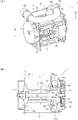
- FIG. 2 is a part development view showing the seat belt retractor according to the first embodiment of the present invention.
- 2A and 2B are diagrams illustrating the seat belt retractor illustrated in FIG. 1, in which FIG. 2A is a perspective view and FIG. 2B is a cross-sectional view taken along the line BB in FIG.
- FIG. 2A is a perspective view
- FIG. 2B is a cross-sectional view taken along the line BB in FIG.
- FIG. 1 is a part development view showing the seat belt retractor according to the first embodiment of the present invention.
- 2A and 2B are views showing the seat belt retractor shown in FIG. 1, wherein FIG. 2A is a perspective view, and FIG. 2B is a cross-sectional view taken along line BB in FIG.
- a seat belt retractor 1 includes a spool 2 that winds up a webbing that restrains an occupant, and a base frame that rotatably accommodates the spool 2. 3, a spring unit 4 that urges the spool 2 in the winding direction, a pretensioner 5 that winds up the webbing to remove slack in an emergency, and a lock mechanism 6 that stops pulling out the webbing in an emergency,
- the pretensioner 5 is connected coaxially to the spool 2 and has a rotating body 51 having a plurality of engaging teeth 51a formed on the outer periphery, and a power generating means for rotating the rotating body 51 by engaging with the engaging teeth 51a. 52 and a cover member 53 that accommodates at least the rotating body 51.
- the cover member 53 is disposed inside the base frame 3, And it is configured to pool 2 possible bearings. In each figure, the webbing is omitted.
- Spool 2 is a winding drum that winds up webbing.
- One end of the spool 2 is connected to the spring unit 4, and the spool 2 is biased in the direction of winding the webbing by the spring spring stored in the spring unit 4.
- the means for applying the winding force to the spool 2 is not limited to the spring unit 4 and may be other means using an electric motor or the like.
- a torsion bar 21 forming an axis is inserted into the cavity formed in the center of the spool 2, and one end of the torsion bar 21 is formed on the inner surface of the end of the spool 2 on the side where the spring unit 4 is connected. The other end of the torsion bar 21 is connected to the locking base 22.
- the configuration of the shock absorbing mechanism including the torsion bar 21 is not limited to the illustrated configuration.
- one end of the torsion bar 21 may pass through the spool 2 and be connected to the spring unit 4. If unnecessary, it may be omitted.
- the locking base 22 has one end inserted through the hollow portion of the spool 2 and the other end rotatably supported by the retainer cover 35. Further, a shaft portion into which a rotating body 51 and a deformation plate 24 described later are fitted is formed on one end side of the locking base 22, and an engaging claw 61 of the lock mechanism 6 is rotatably disposed on the other end side.
- the torsion bar 21 is configured to rotate integrally with the spool 2. Further, when the pretensioner 5 is operated, the webbing can be wound around the spool 2 by rotating the torsion bar 21. Further, when the lock mechanism 6 is operated, the rotation of the torsion bar 21 is restrained, and the rotation of the spool 2 is locked to suppress the webbing from being pulled out.
- the spool 2 is cantilevered by the torsion bar 21, so that the load of the webbing can be limited by the torsional deformation of the torsion bar 21. Absorbs impact energy.
- a metal deformation pin 23 is inserted into the end surface of the spool 2 on the side where the pretensioner 5 is disposed so as to expose the head. Further, a deformation plate 24 having a convex portion that can be engaged with the head of the deformation pin 23 is fitted into the shaft portion of the locking base 22. In addition, the deformation pin 23 and the deformation plate 24 may be integrally formed.
- the energy absorption capability can be improved.
- the deformation pin 23 and the deformation plate 24 may be omitted.
- the base frame 3 is a housing that forms the skeleton of the seat belt retractor 1.
- the base frame 3 includes, for example, a pair of end surfaces 31 and 32 that face each other, a side surface 33 that connects these end surfaces, and a tie plate 34 that faces the side surface 33 and is connected to the end surfaces 31 and 32.
- the spring unit 4 is disposed outside the end surface 31, the pretensioner 5 is disposed inside the end surface 32, and the lock mechanism 6 is disposed outside the end surface 32.
- the lock mechanism 6 is accommodated in a retainer cover 35 connected to the base frame 3.
- the retainer cover 35 is provided with a vehicle sensor 7 that detects sudden deceleration or inclination of the vehicle body.
- the vehicle sensor 7 has a built-in spherical mass body (not shown) and an actuator 71 that is swung by the movement of the mass body, and is housed in a recess formed in the retainer cover 35.
- the vehicle sensor 7 is configured such that when the vehicle body suddenly decelerates or tilts, the mass body moves upward, and accordingly, the tip of the actuator 71 swings upward. By this swinging, the actuator 71 is locked to an external tooth 62a of the lock gear 62 described later. Further, the vehicle sensor 7 may be configured to transmit a detection signal to other electronic components or an electric control system mounted on the vehicle when the vehicle body suddenly decelerates or tilts.
- the pretensioner 5 includes a rotating body 51 connected to the end of the spool 2 via the torsion bar 21 and the locking base 22, power generation means 52 that rotates the rotating body 51, and a cover member 53 that houses the rotating body 51. And have.
- the rotating body 51 has a plurality of engaging teeth 51a formed so as to protrude outward in the radial direction.
- the power generation means 52 includes, for example, an ejection body 52a that engages with the engagement teeth 51a to rotate the rotating body 51, a guide pipe 52b that houses the ejection body 52a and guides driving, and an end portion of the guide pipe 52b And a gas generator 52c that applies power to the injection body 52a.
- the injection body 52a is, for example, a synthetic resin rod, and is formed so as to move while plastically deforming along the shape of the guide pipe 52b within the guide pipe 52b when pressure is applied to the end of the injection body 52a. ing. Further, the projecting body 52a is set to such a length that the rear end is not discharged from the guide pipe 52b when the pretensioner 5 is in an operation-completed state. With this configuration, it is possible to suppress the release of gas from the guide pipe 52b to the outside after the pretensioner 5 is activated.
- the injection body 52a is not limited to the rod member.
- the injection body 52a uses a plurality of metal or resin spheres or a plurality of twin balls connected with two metal or resin spheres. It may be used.
- the guide pipe 52b is disposed at a position where the front end faces the engaging teeth 51a of the rotating body 51, and the rear end side is extended by a length necessary for the movement of the injection body 52a to be the outer shape of the seat belt retractor 1.
- a notch 52d is formed in a part of the outer periphery, and the engaging teeth 51a of the rotating body 51 pass through the guide pipe 52b and can rotate from the notch 52d. Yes.
- the gas generator 52c is, for example, a micro gas generator that ejects gas to the guide pipe 52b in response to detection signals from the vehicle sensor 7 and an acceleration sensor mounted on the vehicle body. Between the gas generator 52c and the injection body 52a, a piston (not shown) that seals the gap between the injection body 52a and the peripheral surface of the guide pipe 52b and forms a pressure receiving surface may be disposed.
- the state in which the injection body 52a is accommodated in the guide pipe 52b is maintained by the rigidity of the injection body 52a at normal times.
- the ejector 52a moves in the guide pipe 52b while being plastically deformed, and is discharged into the cover member 53 from the tip of the guide pipe 52b.
- the injection body 52a engages with the engaging teeth 51a of the rotating body 51 while plastically deforming, and rotates the engaging teeth 51a in the direction of the arrow in the figure.
- the projecting body 52a moves along the outer shape of the cover member 53, and finally comes into contact with the guide pipe 52b, the projecting body 52a, the cover member 53, or other parts and stops.
- the cover member 53 is a metal part having a substantially bowl shape or a box shape, and is fixed to the inside of the end surface 32 and the side surface 33 of the base frame 3. Further, as shown in FIGS. 1 and 2B, the cover member 53 has an opening 53a through which the end of the spool 2 can be inserted, and the deformation plate 24 is interposed by the inner edge of the opening 53a. Thus, it is configured to indirectly support the radial load of the spool 2, and the opening 53 a constitutes a bearing of the spool 2.
- the inner edge side of the opening 53a is bent toward the end face 32 to form a bent portion 53b, and the bent portion 53b constitutes a bearing.
- a bearing may be formed so that the radial load of the spool 2 is directly supported by the inner edge of the opening 53 a of the cover member 53, or the deformation plate 24. You may make it bearing the spool 2 via components other than. Further, the bent portion 53b may be formed by bending the inner edge side of the opening portion 53a toward the end face 31 side.
- the end portion of the spool 2 is also rotatably supported by the retainer cover 35, a small load bearing can be formed by the retainer cover 35 and a large load bearing can be formed by the cover member 53. .
- the thrust load of the spool 2 can be supported by the retainer cover 35 or by the cover member 53.
- the lock mechanism 6 includes an engaging claw 61 (pawl) that is swingably disposed on the end surface 32 of the locking base 22, a lock gear 62 that rotates the engaging claw 61 inward, a lock gear 62, and a retainer. And a flywheel 63 disposed in a space formed between the cover 35 and the cover 35.
- An opening 32a through which the locking base 22 can be inserted is formed on the end surface 32 of the base frame 3, and internal teeth are cut at the inner edge of the opening 32a.
- the engaging claw 61 is disposed so as to be able to engage with the internal teeth of the opening 32a.
- the lock gear 62 is inserted into a shaft portion supported by the retainer cover 35 of the locking base 22, and external teeth 62a are formed on the outer periphery.
- An actuator 71 of the vehicle sensor 7 is engaged with the external teeth 62a.
- a flywheel 63 is swingably disposed outside the lock gear 62.
- a circular recess is formed in the retainer cover 35, and an inner tooth 35a is formed inside the recess.
- the tip of the flywheel 63 is engaged with the internal teeth 35a. Note that the flywheel 63 is urged by a spring (not shown) in a direction in which a tip portion is separated from the internal teeth 35a.
- a cam hole 62b is formed in the flat portion of the lock gear 62 so as to bend from the outer edge side toward the inner edge side.
- a pin (not shown) formed on the side surface of the engaging claw 61 is inserted into the cam hole 62b, and the pin moves along the cam hole 62b with the rotation of the lock gear 62.
- the pawl 61 is swung.
- the engaging claw 61 may be urged by a spring (not shown) in a direction in which the tip portion is separated from the internal teeth of the opening 32a.
- the flywheel 63 is a mass body that is swingably disposed between the retainer cover 35 and the lock gear 62.
- the biasing force (spring elastic force) of the flywheel 63 is set to be larger than the inertial force generated in the flywheel 63. At this time, the flywheel 63 rotates together with the lock gear 62.
- the inertial force generated in the flywheel 63 becomes larger than the urging force (elastic force of the spring), and the tip of the flywheel 63 has the retainer cover 35.
- the inner teeth 35a are approached and engaged.
- the actuator 71, the flywheel 63, and the engagement claw 61 are normally in a non-engagement state, so that the locking base 22 and the lock gear 62 are rotated as the spool 2 rotates. It will rotate.
- the actuator 71 engages with the external teeth 62a of the lock gear 62, and the rotation of the lock gear 62 is restricted. If the webbing is to be pulled out in this state, relative rotation occurs between the locking base 22 and the lock gear 62, and the engaging claw 61 moves along the cam hole 62 b along with this, and the tip of the engaging claw 61 is moved. The portion engages with internal teeth formed at the inner edge of the opening 32 a of the base frame 3. As a result, the rotation of the locking base 22 is restricted.
- the side surface of the base frame 3 can be used as a bearing for the spool 2 by arranging the cover member 53 of the pretensioner 5 inside the base frame 3.
- the pretensioner plate and the bearing ring that have been conventionally arranged separately from the cover member 53 can be omitted, and the number of parts can be reduced.
- the pretensioner 5 is arranged inside the base frame 3, the parts arranged outside the base frame 3 can be reduced, and the seat belt retractor 1 can be downsized.
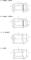
- FIG. 3 is a figure which shows the basic concept of this invention
- (A) is the prior art which shows the comparative example 1
- (B) is the prior art which shows the comparative example 2
- (C) is 1st embodiment.
- (D) shows a modified example.
- the configuration of the seat belt retractor 1 is conceptualized.
- a seat belt retractor 1 ′ according to the prior art (Comparative Example 1) shown in FIG. 3 (A) is, for example, described in Patent Document 1.
- a lock mechanism 6 ′ is disposed on one side of the base frame 3 ′, and a pretensioner 5 ′ and a spring unit 4 ′ are disposed on the opposite side.
- an engaging claw (not shown) of the lock mechanism 6 ′ is engaged with an internal tooth (not shown) of an opening formed in the end surface 32 ′ of the base frame 3 ′. Therefore, the spool 2 'cannot be supported by the opening of the base frame 3'. Therefore, a bearing component 50 '(for example, a pretensioner plate) is disposed between the base frame 3' and the pretensioner 5 '.
- a seat belt retractor 1 ′ according to the conventional technique (Comparative Example 2) shown in FIG. 3 (B) is, for example, described in Patent Document 2.
- a spring unit 4 ′ is disposed on one side of the base frame 3 ′, and a pretensioner 5 ′ and a lock mechanism 6 ′ are disposed on the opposite side.
- the engagement claw (not shown) of the lock mechanism 6 ′ is an internal tooth (not shown) formed in the end surface 32 ′ of the base frame 3 ′. Therefore, the spool 2 'cannot be supported by the opening of the base frame 3'. Therefore, a bearing component 50 '(for example, a bearing ring) is disposed between the base frame 3' and the pretensioner 5 '.
- the seat belt retractor 1 according to the first embodiment shown in FIG. 3C is the one shown in FIGS.
- a pretensioner 5 is disposed on one inner side of the base frame 3
- a lock mechanism 6 is disposed on one outer side
- a spring unit 4 is disposed on the opposite one side.
- the seat belt retractor 1 has an opening portion 32a in which an engaging claw 61 of the lock mechanism 6 is formed on the end surface 32 of the base frame 3, as in the prior art. Therefore, the spool 2 cannot be supported by the opening 32 a of the base frame 3. Therefore, in the present embodiment, the pretensioner 5 is disposed inside the base frame 3, and the spool 2 is supported by the opening 53 a formed in the cover member 53.
- the seat belt retractor 1 according to the modification of the first embodiment shown in FIG. 3 (D) is obtained by replacing the arrangement of the spring unit 4 and the lock mechanism 6 shown in FIG. 3 (C).
- the lock mechanism 6 that stops pulling out the webbing in an emergency may be arranged outside the end face 32 of the base frame 3 on which the cover member 53 is arranged, and the spool 2 is urged in the winding direction.
- a spring unit 4 may be arranged.
- the arrangement of the spring unit 4 and the lock mechanism 6 is arbitrarily set according to the configuration of the seat belt retractor 1.
- the configuration of the seat belt retractor 1 shown in FIGS. 3A to 3D is a conceptual diagram in which the structure is simplified.
- the lock mechanisms 6 and 6 ′ include a lock frame and a pawl in which the base frame 3 It may be arranged separately in the two rules.
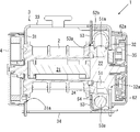
- FIG. 4 is a figure which shows a frame body, (A) is a front perspective view, (B) is a back perspective view, (C) has shown the modification.
- the metal parts such as the base frame 3 and the guide pipe 52b of the pretensioner 5 described above may be coated with an anticorrosion film from the viewpoint of preventing corrosion.
- an anticorrosion film from the viewpoint of preventing corrosion.
- the frame member 100 in which the guide pipe 52b and the cover member 53 are fixed to the base frame 3 is formed by arranging the cover member 53 inside the base frame 3. Then, other parts can be assembled through the opening 32 a formed in the end surface 32 of the base frame 3. Therefore, after forming the frame body 100, the anticorrosion paint can be impregnated to coat the frame body 100 with the anticorrosion coating, and a plurality of parts can be collectively subjected to the anticorrosion treatment. The burden of processing work can be reduced.
- the cover member is the base frame 3. It had to be fixed to the end face 32 of '.
- the cover member 53 is disposed inside the base frame 3 so that the cover member 53 is connected to both the end surface 32 and the side surface 33 of the base frame 3.
- the cover member 53 can be firmly fixed.
- a plurality of protrusions 53 c are formed on the outer periphery of the cover member 53, and these protrusions 53 c are openings formed on the end surface 32 and the side surface 33 of the base frame 3.
- the cover member 53 can be fixed to the base frame 3 by inserting it into the frame or arranging it along the edge and then bending it by caulking as necessary.
- the protrusion 53c of the cover member 53 is inserted into the insertion portion 3a formed on the side surface 33 of the base frame 3 and the penetration portion 3b formed on the end surface 32. You may do it.
- the insertion part 3a is configured by a bridge part in which a part of the side surface 33 of the cover frame 3 is raised inward.
- the inserted protrusion 53c may be bent or may not be bent. Further, the arrangement of the protrusions 53 c is not limited to the illustrated configuration, and is arbitrarily arranged according to the shapes of the base frame 3 and the cover member 53.
- FIG. 5 is a sectional view showing the seat belt retractor according to the second embodiment of the present invention.
- This cross-sectional view is the same cross-sectional view as the BB arrow cross-sectional view shown in FIG.
- symbol is attached
- the arrangement of the base frame 3, the spring unit 4, the pretensioner 5 and the lock mechanism 6 is the same as the seat belt retractor 1 according to the first embodiment described above.
- the cover member 53 in the second embodiment has the same basic configuration as that of the first embodiment described above, but does not have the bent portion 53b in the opening 53a. Thus, whether or not the bent portion 53b is formed in the opening 53a can be arbitrarily set.
- a guide member 54 for guiding the movement of the ejected body 52a discharged into the cover member 53 is disposed.
- the guide member 54 is formed so that the injection body 52 a moves along the outer shape of the cover member 53. Therefore, the guide member 54 can prevent the ejected ejector 52a from interfering with the rotating body 51 (whether or not formed integrally with the locking base 22). Can be stabilized.
- the guide member 54 may have a shape that is inserted into the outside of the deformation plate 24.
- the radial load of the spool 2 may be indirectly supported by supporting the outer peripheral portion of the guide member 54 with the opening 53 a of the cover member 53.
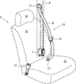
- FIG. 6 is an overall configuration diagram showing the seat belt device according to the embodiment of the present invention.
- components other than the seat belt device are illustrated by a one-dot chain line.
- a seat belt device 10 includes a webbing W that restrains an occupant, a seat belt retractor 1 that winds the webbing W, and a guide anchor 11 that is provided on the vehicle body side and guides the webbing W.
- the seat belt retractor 1 is shown in FIG. As described above, the spool 2 that winds the webbing W, the base frame 3 that rotatably supports the spool 2, the spring unit 4 that biases the spool 2 in the winding direction, and the webbing W that is wound in an emergency.
- the seat S includes, for example, a seat part S1 on which an occupant sits, a backrest part S2 located on the back of the occupant, and a headrest part S3 that supports the head of the occupant.
- the seat belt retractor 1 is built in, for example, the B pillar P of the vehicle body.
- the buckle 13 is often disposed on the side surface of the seat portion S1
- the belt anchor 12 is often disposed on the lower surface of the seat portion S1.
- the guide anchor 11 is often disposed on the B pillar P.
- the webbing W has one end connected to the belt anchor 12 and the other end connected to the seat belt retractor 1 via the guide anchor 11.
- the webbing W is pulled out from the seat belt retractor 1 while sliding through the insertion hole of the guide anchor 11.
- the webbing W is wound up to a certain load by the action of the spring unit 4 of the seat belt retractor 1.
- the above-described seat belt device 10 is obtained by applying the above-described seat belt retractor 1 according to the present embodiment to a normal seat belt device in a front seat. Therefore, also in the seat belt device 10 according to the present embodiment, the number of parts and the size of the seat belt retractor 1 can be reduced.
- the seatbelt apparatus 10 is not limited to application to a front seat,
- the guide anchor 11 is abbreviate
- the present invention is not limited to the above-described embodiments, and various modifications can be made without departing from the spirit of the present invention, for example, it may be applied to a seat belt device used for a vehicle other than a vehicle. Of course.
Landscapes
- Engineering & Computer Science (AREA)
- Mechanical Engineering (AREA)
- Automotive Seat Belt Assembly (AREA)
Priority Applications (3)
| Application Number | Priority Date | Filing Date | Title |
|---|---|---|---|
| CN201480050513.1A CN105531160B (zh) | 2013-09-13 | 2014-09-03 | 安全带卷收器及安全带装置 |
| US15/021,488 US10017150B2 (en) | 2013-09-13 | 2014-09-03 | Seat belt retractor and seat belt apparatus |
| EP14844246.0A EP3045356B1 (en) | 2013-09-13 | 2014-09-03 | Seat belt retractor and seat belt device |
Applications Claiming Priority (2)
| Application Number | Priority Date | Filing Date | Title |
|---|---|---|---|
| JP2013190246A JP6145368B2 (ja) | 2013-09-13 | 2013-09-13 | シートベルトリトラクタ及びシートベルト装置 |
| JP2013-190246 | 2013-09-13 |
Publications (1)
| Publication Number | Publication Date |
|---|---|
| WO2015037487A1 true WO2015037487A1 (ja) | 2015-03-19 |
Family
ID=52665594
Family Applications (1)
| Application Number | Title | Priority Date | Filing Date |
|---|---|---|---|
| PCT/JP2014/073155 Ceased WO2015037487A1 (ja) | 2013-09-13 | 2014-09-03 | シートベルトリトラクタ及びシートベルト装置 |
Country Status (5)
| Country | Link |
|---|---|
| US (1) | US10017150B2 (enExample) |
| EP (1) | EP3045356B1 (enExample) |
| JP (1) | JP6145368B2 (enExample) |
| CN (1) | CN105531160B (enExample) |
| WO (1) | WO2015037487A1 (enExample) |
Cited By (2)
| Publication number | Priority date | Publication date | Assignee | Title |
|---|---|---|---|---|
| US20200238949A1 (en) * | 2015-10-21 | 2020-07-30 | Takata Corporation | Seat belt retractor and seat belt device |
| US11964626B2 (en) | 2020-11-13 | 2024-04-23 | Joyson Safety Systems Japan G.K. | Seat belt retractor and seat belt device |
Families Citing this family (18)
| Publication number | Priority date | Publication date | Assignee | Title |
|---|---|---|---|---|
| GB201413898D0 (en) * | 2014-08-06 | 2014-09-17 | Moog Controls Ltd | Firing mechanism |
| DE102016104614B4 (de) | 2016-03-14 | 2018-04-05 | Autoliv Development Ab | Gurtaufroller mit einer Kraftbegrenzungseinrichtung |
| US10315617B2 (en) * | 2016-08-04 | 2019-06-11 | Trw Vehicle Safety Systems Inc. | Seat belt retractor with load limiting stop mechanism |
| JP6732599B2 (ja) * | 2016-08-10 | 2020-07-29 | Joyson Safety Systems Japan株式会社 | プリテンショナ、リトラクタ及びシートベルト装置 |
| DE102016118469B4 (de) | 2016-09-29 | 2025-05-22 | Zf Automotive Germany Gmbh | Gurtstraffer |
| JP6894227B2 (ja) * | 2016-12-16 | 2021-06-30 | Joyson Safety Systems Japan株式会社 | 駆動輪の製造方法 |
| JP6539638B2 (ja) | 2016-12-19 | 2019-07-03 | 株式会社東海理化電機製作所 | ウェビング巻取装置 |
| CN110304013B (zh) * | 2018-03-27 | 2021-10-22 | 比亚迪股份有限公司 | 卷带装置及车辆 |
| US10864886B2 (en) * | 2019-02-22 | 2020-12-15 | Autoliv Asp, Inc. | Retractor pretensioner assembly |
| JP6843182B2 (ja) * | 2019-06-04 | 2021-03-17 | 株式会社東海理化電機製作所 | ウェビング巻取装置 |
| CN110329205B (zh) * | 2019-07-17 | 2020-10-09 | 重庆光大产业有限公司 | 一种可对弯管全方位固定的卷收器 |
| JP7530713B2 (ja) * | 2019-12-11 | 2024-08-08 | Joyson Safety Systems Japan合同会社 | シートベルトリトラクタ及びシートベルト装置 |
| US11926280B2 (en) * | 2019-12-31 | 2024-03-12 | Joyson Safety Systems Acquisition Llc | Seat belt pretensioner |
| CN111114488A (zh) * | 2020-01-16 | 2020-05-08 | 重庆光大产业有限公司 | 预紧式卷收器及安全带装置 |
| JP7719663B2 (ja) * | 2021-08-20 | 2025-08-06 | Joyson Safety Systems Japan合同会社 | リトラクタ及びシートベルト装置 |
| JP2024037090A (ja) * | 2022-09-06 | 2024-03-18 | Joyson Safety Systems Japan合同会社 | リトラクタ及びシートベルト装置 |
| JP2024127326A (ja) * | 2023-03-09 | 2024-09-20 | 芦森工業株式会社 | シートベルト用リトラクタ |
| DE102024106568A1 (de) * | 2023-03-09 | 2024-09-12 | Ashimori Industry Co., Ltd. | Sicherheitsgurtaufroller |
Citations (5)
| Publication number | Priority date | Publication date | Assignee | Title |
|---|---|---|---|---|
| JP2001163182A (ja) * | 1999-12-13 | 2001-06-19 | Takata Corp | プリテンショナ |
| JP2001301567A (ja) * | 2000-04-24 | 2001-10-31 | Takata Corp | シートベルト巻取り装置 |
| JP2002145012A (ja) | 2000-11-06 | 2002-05-22 | Takata Corp | シートベルトリトラクタ |
| JP2002326558A (ja) * | 2001-05-01 | 2002-11-12 | Takata Corp | シートベルト巻き取り装置の制御方法 |
| JP2012509808A (ja) | 2008-11-27 | 2012-04-26 | オートリブ ディベロップメント エービー | 負荷制限装置および引張装置を有するシートベルトリトラクタ |
Family Cites Families (22)
| Publication number | Priority date | Publication date | Assignee | Title |
|---|---|---|---|---|
| DE2026277C3 (de) * | 1970-05-29 | 1974-07-11 | Ernst Prof. Dipl.-Ing. Dr. Techn. 3300 Braunschweig Fiala | Vorrichtung zum Aufnehmen von Energie für Rückhalteeinrichtungen für Fahrzeuginsassen, insbesondere für Sicherheitsgurte |
| US5383623A (en) * | 1992-02-13 | 1995-01-24 | Takata Corporation | Rotary actuator-operated seat belt pretensioner |
| JP2526348B2 (ja) * | 1992-05-27 | 1996-08-21 | タカタ株式会社 | ロ―タリアクチュエ―タ作動プリテンショナ |
| JPH0624294A (ja) * | 1992-07-08 | 1994-02-01 | Takata Kk | シートベルト装置のプリテンショナ |
| US5485970A (en) * | 1994-03-21 | 1996-01-23 | Trw Vehicle Safety Systems Inc. | Seat belt pretensioner |
| US5881962A (en) * | 1994-04-11 | 1999-03-16 | Autoliv Development Ab | Mass-body drive for a rotary tightening device |
| US5690295A (en) * | 1995-08-02 | 1997-11-25 | Autoliv Development Ab | Mass body drive for a rotational tensioning device |
| US6722600B2 (en) | 1999-02-26 | 2004-04-20 | Takata Corporation | Seat belt retractor |
| US7124974B2 (en) | 1999-02-26 | 2006-10-24 | Takata Corporation | Seat belt retractor |
| US6419176B1 (en) * | 1999-02-26 | 2002-07-16 | Takata Corporation | Pre-tensioner |
| JP4654489B2 (ja) * | 2000-06-16 | 2011-03-23 | タカタ株式会社 | シートベルト巻取装置 |
| EP1405777B1 (en) * | 2002-10-03 | 2005-06-29 | Key Safety Systems, Inc. | Retractor |
| JP4295552B2 (ja) | 2003-05-16 | 2009-07-15 | 株式会社東海理化電機製作所 | ウエビング巻取装置 |
| US7761207B2 (en) * | 2004-10-29 | 2010-07-20 | Autoliv Development Ab | Seat belt device |
| US8459583B2 (en) * | 2008-04-04 | 2013-06-11 | Autoliv Development Ab | Seat belt retractor |
| US7988084B2 (en) * | 2008-08-21 | 2011-08-02 | Autoliv Asp, Inc. | Device for pretensioning a seatbelt |
| JP5317945B2 (ja) * | 2009-12-15 | 2013-10-16 | タカタ株式会社 | シートベルトリトラクタおよびこれを備えたシートベルト装置 |
| JP5455597B2 (ja) * | 2009-12-15 | 2014-03-26 | タカタ株式会社 | シートベルトリトラクタおよびこれを備えたシートベルト装置 |
| US8220735B2 (en) * | 2009-12-22 | 2012-07-17 | Autoliv Asp, Inc. | Adaptive load limiting retractor |
| US20120049500A1 (en) * | 2010-08-31 | 2012-03-01 | Bin Wang | Dual Stage Pretensioning and High Pay-In Capacity Pretensioning Retractor |
| JP5653739B2 (ja) * | 2010-12-13 | 2015-01-14 | タカタ株式会社 | プリテンショナー、これを有するシートベルトリトラクタおよびこれを備えたシートベルト装置 |
| US9079565B2 (en) * | 2013-03-14 | 2015-07-14 | Autoliv Asp, Inc. | Progressive load limiting restraint system |
-
2013
- 2013-09-13 JP JP2013190246A patent/JP6145368B2/ja active Active
-
2014
- 2014-09-03 CN CN201480050513.1A patent/CN105531160B/zh active Active
- 2014-09-03 US US15/021,488 patent/US10017150B2/en not_active Expired - Fee Related
- 2014-09-03 EP EP14844246.0A patent/EP3045356B1/en not_active Not-in-force
- 2014-09-03 WO PCT/JP2014/073155 patent/WO2015037487A1/ja not_active Ceased
Patent Citations (5)
| Publication number | Priority date | Publication date | Assignee | Title |
|---|---|---|---|---|
| JP2001163182A (ja) * | 1999-12-13 | 2001-06-19 | Takata Corp | プリテンショナ |
| JP2001301567A (ja) * | 2000-04-24 | 2001-10-31 | Takata Corp | シートベルト巻取り装置 |
| JP2002145012A (ja) | 2000-11-06 | 2002-05-22 | Takata Corp | シートベルトリトラクタ |
| JP2002326558A (ja) * | 2001-05-01 | 2002-11-12 | Takata Corp | シートベルト巻き取り装置の制御方法 |
| JP2012509808A (ja) | 2008-11-27 | 2012-04-26 | オートリブ ディベロップメント エービー | 負荷制限装置および引張装置を有するシートベルトリトラクタ |
Non-Patent Citations (1)
| Title |
|---|
| See also references of EP3045356A4 |
Cited By (2)
| Publication number | Priority date | Publication date | Assignee | Title |
|---|---|---|---|---|
| US20200238949A1 (en) * | 2015-10-21 | 2020-07-30 | Takata Corporation | Seat belt retractor and seat belt device |
| US11964626B2 (en) | 2020-11-13 | 2024-04-23 | Joyson Safety Systems Japan G.K. | Seat belt retractor and seat belt device |
Also Published As
| Publication number | Publication date |
|---|---|
| JP6145368B2 (ja) | 2017-06-07 |
| CN105531160B (zh) | 2018-07-06 |
| JP2015054650A (ja) | 2015-03-23 |
| US20160221534A1 (en) | 2016-08-04 |
| EP3045356B1 (en) | 2019-08-07 |
| US10017150B2 (en) | 2018-07-10 |
| EP3045356A1 (en) | 2016-07-20 |
| CN105531160A (zh) | 2016-04-27 |
| EP3045356A4 (en) | 2017-06-14 |
Similar Documents
| Publication | Publication Date | Title |
|---|---|---|
| JP6145368B2 (ja) | シートベルトリトラクタ及びシートベルト装置 | |
| WO2015037485A1 (ja) | シートベルトリトラクタ及びシートベルト装置 | |
| JP5428080B2 (ja) | シートベルト用リトラクタ | |
| JP5388042B2 (ja) | シートベルト用リトラクタ | |
| US9278667B2 (en) | Pretensioner, seat belt retractor, and seat belt device | |
| JP5841519B2 (ja) | シートベルトリトラクタ | |
| JP6629038B2 (ja) | シートベルトリトラクタ及びシートベルト装置 | |
| US10246047B2 (en) | Seat belt retractor and seat belt apparatus | |
| JP6775361B2 (ja) | プリテンショナ、リトラクタ及びシートベルト装置 | |
| JP6871037B2 (ja) | シートベルトリトラクタ及びシートベルト装置 | |
| JP6549879B2 (ja) | シートベルトリトラクタ及びシートベルト装置 | |
| JP6732599B2 (ja) | プリテンショナ、リトラクタ及びシートベルト装置 | |
| JP2006137290A (ja) | ウエビング巻取装置 | |
| JP2017154525A (ja) | プリテンショナ、リトラクタ及びシートベルト装置 | |
| JP2020175754A (ja) | リトラクタ及びシートベルト装置 | |
| JP2020104815A (ja) | プリテンショナ、リトラクタ及びシートベルト装置 | |
| JP2017159843A (ja) | プリテンショナ、リトラクタ及びシートベルト装置 | |
| JP7354015B2 (ja) | プリテンショナ、リトラクタ及びシートベルト装置 | |
| JP5263626B2 (ja) | シートベルト用リトラクタ | |
| JP6498070B2 (ja) | ウェビング巻取装置 | |
| JP2020044901A (ja) | シートベルトリトラクタ及びシートベルト装置 | |
| JP2013047099A (ja) | シートベルト用リトラクタ |
Legal Events
| Date | Code | Title | Description |
|---|---|---|---|
| WWE | Wipo information: entry into national phase |
Ref document number: 201480050513.1 Country of ref document: CN |
|
| 121 | Ep: the epo has been informed by wipo that ep was designated in this application |
Ref document number: 14844246 Country of ref document: EP Kind code of ref document: A1 |
|
| WWE | Wipo information: entry into national phase |
Ref document number: 15021488 Country of ref document: US |
|
| NENP | Non-entry into the national phase |
Ref country code: DE |
|
| REEP | Request for entry into the european phase |
Ref document number: 2014844246 Country of ref document: EP |
|
| WWE | Wipo information: entry into national phase |
Ref document number: 2014844246 Country of ref document: EP |