EP3045356B1 - Seat belt retractor and seat belt device - Google Patents
Seat belt retractor and seat belt device Download PDFInfo
- Publication number
- EP3045356B1 EP3045356B1 EP14844246.0A EP14844246A EP3045356B1 EP 3045356 B1 EP3045356 B1 EP 3045356B1 EP 14844246 A EP14844246 A EP 14844246A EP 3045356 B1 EP3045356 B1 EP 3045356B1
- Authority
- EP
- European Patent Office
- Prior art keywords
- seat belt
- spool
- disposed
- webbing
- base frame
- Prior art date
- Legal status (The legal status is an assumption and is not a legal conclusion. Google has not performed a legal analysis and makes no representation as to the accuracy of the status listed.)
- Not-in-force
Links
- 230000007246 mechanism Effects 0.000 claims description 32
- 230000000052 comparative effect Effects 0.000 description 7
- 239000002184 metal Substances 0.000 description 6
- 230000004048 modification Effects 0.000 description 6
- 238000012986 modification Methods 0.000 description 6
- 230000001133 acceleration Effects 0.000 description 5
- 238000010521 absorption reaction Methods 0.000 description 4
- 230000009467 reduction Effects 0.000 description 4
- 238000005452 bending Methods 0.000 description 3
- 238000010586 diagram Methods 0.000 description 3
- 229920003002 synthetic resin Polymers 0.000 description 3
- 239000000057 synthetic resin Substances 0.000 description 3
- 239000011248 coating agent Substances 0.000 description 2
- 238000000576 coating method Methods 0.000 description 2
- 238000001514 detection method Methods 0.000 description 2
- 239000003973 paint Substances 0.000 description 2
- 230000002093 peripheral effect Effects 0.000 description 2
- 230000009471 action Effects 0.000 description 1
- 238000013459 approach Methods 0.000 description 1
- 230000007797 corrosion Effects 0.000 description 1
- 238000005260 corrosion Methods 0.000 description 1
- 230000003247 decreasing effect Effects 0.000 description 1
- 230000000694 effects Effects 0.000 description 1
- 230000004044 response Effects 0.000 description 1
- 239000011435 rock Substances 0.000 description 1
- 238000004804 winding Methods 0.000 description 1
Images
Classifications
-
- B—PERFORMING OPERATIONS; TRANSPORTING
- B60—VEHICLES IN GENERAL
- B60R—VEHICLES, VEHICLE FITTINGS, OR VEHICLE PARTS, NOT OTHERWISE PROVIDED FOR
- B60R22/00—Safety belts or body harnesses in vehicles
- B60R22/34—Belt retractors, e.g. reels
- B60R22/36—Belt retractors, e.g. reels self-locking in an emergency
-
- B—PERFORMING OPERATIONS; TRANSPORTING
- B60—VEHICLES IN GENERAL
- B60R—VEHICLES, VEHICLE FITTINGS, OR VEHICLE PARTS, NOT OTHERWISE PROVIDED FOR
- B60R22/00—Safety belts or body harnesses in vehicles
- B60R22/34—Belt retractors, e.g. reels
- B60R22/46—Reels with means to tension the belt in an emergency by forced winding up
- B60R22/4628—Reels with means to tension the belt in an emergency by forced winding up characterised by fluid actuators, e.g. pyrotechnic gas generators
-
- B—PERFORMING OPERATIONS; TRANSPORTING
- B60—VEHICLES IN GENERAL
- B60R—VEHICLES, VEHICLE FITTINGS, OR VEHICLE PARTS, NOT OTHERWISE PROVIDED FOR
- B60R22/00—Safety belts or body harnesses in vehicles
- B60R22/34—Belt retractors, e.g. reels
- B60R2022/3402—Retractor casings; Mounting thereof
Definitions
- the present invention relates to a seat belt retractor and a seat belt apparatus, and more specifically, to a seat belt retractor suitable for the reduction in the number of components, size, and weight, and a seat belt apparatus having the seat belt retractor.
- US2012/0049500 A1 is the closest prior art document and discloses the preamble of claim 1.
- Vehicles such as automobiles are generally provided with a seat belt apparatus that restrains an occupant in a seat including a seat portion in which the occupant is seated and a backrest portion located behind the occupant.
- a seat belt apparatus includes a webbing that restrains an occupant, a seat belt retractor that retracts the webbing, a guide anchor that is provided on the vehicle body side and that guides the webbing, a belt anchor that fixes the webbing to the vehicle body, a buckle disposed on the side of the seat, and a tongue disposed on the webbing, and restrains the occupant in the seat with the webbing by fitting the tongue into the buckle.
- a seat belt apparatus one end of the webbing is fixed to the belt anchor, and the other end of the webbing is passed through the guide anchor and is connected to the seat belt retractor.
- Such a seat belt retractor includes a locking mechanism that stops the withdrawal of the webbing when the vehicle is inclined or rapidly decreased in speeds in a vehicle collision or the like, and a pretensioner that takes up the slack in the webbing in a vehicle collision or the like (see, for example, Patent Literature 1 and Patent Literature 2).
- a locking mechanism (4, 5) is disposed on one outer side (1A) of a base frame (1)
- a pretensioner (10) including driving means (11, 12, 15) and the like is disposed on the other outer side (1B) of the base frame (1)
- a spring unit (8) is disposed on the outer side thereof.
- a pretensioner plate (31) for rotatably supporting a spool is disposed between the base frame and the pretensioner.
- a spring unit is disposed on one outer side of a base frame (8)
- a pretensioner including a drive unit (7) is disposed on the other outer side of the base frame (8)
- a locking mechanism including a pawl (4) and a control unit (10) is disposed on the outer side thereof.
- a bearing ring (13) for rotatably supporting a spool is disposed between the base frame and the pretensioner.
- the seat belt retractor has a complex mechanism and a large number of components, and therefore there is a problem in that cost reduction is difficult. Because the above-described seat belt retractor is a component disposed in a small space of a vehicle body, reduction in size and weight is desired. However, as described in Patent Literature 1 and Patent Literature 2, the spring unit, locking mechanism, and pretensioner are disposed on both sides of the base frame, and therefore there is a problem in that reduction in size and weight is difficult.
- the present invention is made in view of such problems, and it is an object of the present invention to provide a seat belt retractor and a seat belt apparatus the number of components of which can be reduced and the size and weight of which can be reduced.
- the present invention provides a seat belt retractor including a spool that retracts a webbing that restrains an occupant, a base frame that rotatably houses the spool, and a pretensioner that retracts the webbing to take up the slack therein in an emergency, wherein the pretensioner includes a rotor that is connected coaxially with the spool and that has a plurality of engaging teeth formed on the outer periphery thereof, a power generating means that engages with the engaging teeth and rotates the rotor, and a cover member that houses at least the rotor, and the cover member is disposed inside the base frame.
- the present invention provides a seat belt apparatus including a webbing that restrains an occupant, a seat belt retractor that retracts the webbing, a belt anchor that fixes the webbing to a vehicle body, a buckle disposed on a side face of a seat, and a tongue disposed on the webbing, wherein the seat belt retractor includes a spool that retracts the webbing, a base frame that rotatably houses the spool, and a pretensioner that retracts the webbing to take up the slack therein in an emergency, the pretensioner includes a rotor that is connected coaxially with the spool and that has a plurality of engaging teeth formed on the outer periphery thereof, a power generating means that engages with the engaging teeth and rotates the rotor, and a cover member that houses at least the rotor, and the cover member is disposed inside the base frame.
- the cover member may be able to bear the spool directly or indirectly.
- the cover member may have an opening through which an end of the spool can be passed, and may be configured to support the radial load of the spool with the inner edge of the opening.
- a locking mechanism that stops the withdrawal of the webbing in an emergency or a spring unit that biases the spool in the retracting direction may be disposed outside the base frame in which the cover member is disposed.
- the power generating means may include an projectile that engages with the engaging teeth and rotates the rotor, a guide pipe that houses the projectile and guides the driving, and a gas generator that is disposed at an end of the guide pipe and that imparts power to the projectile.
- the cover member of the pretensioner since the cover member of the pretensioner is disposed inside the base frame, the opening of the cover member can be used as a bearing for the spool or as part of the locking mechanism, a pretensioner plate and a bearing ring that are conventionally disposed separately from the cover member can be omitted, and the number of components can be reduced.
- the pretensioner since the pretensioner is disposed inside the base frame, the degree of freedom in designing the locking mechanism and the pretensioner can be improved, an optimum arrangement can be achieved, and the size and weight of the seat belt retractor can be reduced.
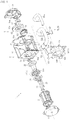
- Fig. 1 is an exploded view showing a seat belt retractor according to a first embodiment of the present invention.
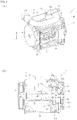
- Fig. 2 shows the seat belt retractor shown in Fig. 1
- (A) is a perspective view
- (B) is a cross-sectional view taken along line B-B of Fig. 2 (A) .
- the seat belt retractor 1 includes, as shown in Fig. 1 and Fig. 2 , a spool 2 that retracts a webbing that restrains an occupant, a base frame 3 that rotatably houses the spool 2, a spring unit 4 that biases the spool 2 in the retracting direction, a pretensioner 5 that retracts the webbing to take up the slack therein in an emergency, and a locking mechanism 6 that stops the withdrawal of the webbing in an emergency.
- the pretensioner 5 has a rotor 51 that is connected coaxially with the spool 2 and that has a plurality of engaging teeth 51a formed on the outer periphery thereof, a power generating means 52 that engages with the engaging teeth 51a and rotates the rotor 51, and a cover member 53 that houses at least the rotor 51.
- the cover member 53 is disposed inside the base frame 3 and can bear the spool 2. In each figure, the depiction of the webbing is omitted.
- the spool 2 is a winding drum that retracts the webbing. One end of the spool 2 is connected to the spring unit 4. The spool 2 is biased in the direction of retracting the webbing by a spiral spring housed in the spring unit 4.
- the means for imparting a retracting force to the spool 2 is not limited to the spring unit 4, and may be another means employing an electric motor or the like.
- a torsion bar 21 forming a central shaft is passed through a cavity formed in the central part of the spool 2.
- One end of the torsion bar 21 is connected to the inner surface of the end of the spool 2 to which the spring unit 4 is connected.
- the other end of the torsion bar 21 is connected to a locking base 22.
- the configuration of the impact absorption mechanism including the torsion bar 21 is not limited to the shown configuration.
- one end of the torsion bar 21 may be connected to the spring unit 4 through the spool 2.
- the configuration of the impact absorption mechanism including the torsion bar 21 may be omitted when unnecessary.
- One end of the locking base 22 is passed through the cavity of the spool 2, and the other end of the locking base 22 is rotatably supported by a retainer cover 35.
- a shaft portion on which the rotor 51 and a deformation plate 24 described later are fitted is formed at one end of the locking base 22, and an engaging pawl 61 of the locking mechanism 6 is rotatably disposed at the other end of the locking base 22.
- the torsion bar 21 rotates integrally with the spool 2.
- the webbing can be retracted on the spool 2 by rotating the torsion bar 21.
- the locking mechanism 6 is in operation, the rotation of the torsion bar 21 is restrained, and the withdrawal of the webbing is suppressed by locking the rotation of the spool 2.
- a deformation pin 23 made of metal is inserted into the end face of the spool 2 on the side on which the pretensioner 5 is disposed such that the head thereof is exposed.
- a deformation plate 24 having a protrusion engageable with the head of the deformation pin 23 is fitted on the shaft portion of the locking base 22.
- the deformation pin 23 and the deformation plate 24 may be formed integrally with each other.
- the energy absorption capacity can be improved.
- the deformation pin 23 and the deformation plate 24 may be omitted.
- the base frame 3 is a case that forms the framework of the seat belt retractor 1.
- the base frame 3 includes, for example, a pair of opposed end faces 31 and 32, a side face 33 connecting these end faces, and a tie plate 34 opposed to the side face 33 and connected to the end faces 31 and 32.
- the spring unit 4 is disposed on the outer side of the end face 31, the pretensioner 5 is disposed on the inner side of the end face 32, and the locking mechanism 6 is disposed on the outer side of the end face 32.
- the locking mechanism 6 is housed in the retainer cover 35 connected to the base frame 3.
- a vehicle sensor 7 that detects rapid deceleration and inclination of the vehicle body is disposed in the retainer cover 35.
- the vehicle sensor 7 has a spherical mass body (not shown) housed therein and an actuator 71 rocked by the movement of the mass body, and is housed in a recess formed in the retainer cover 35.
- Such a vehicle sensor 7 is configured such that when rapid deceleration or inclination occurs in the vehicle body, the mass body moves upward, and accordingly the tip of the actuator 71 is rocked upward. By this rocking, the actuator 71 is engaged with external teeth 62a of a lock gear 62 described later.
- the vehicle sensor 7 may also be configured to transmit a detection signal to other electronic components and an electric control system mounted on the vehicle when rapid deceleration or inclination of the vehicle body is detected.
- the pretensioner 5 includes a rotor 51 that is connected to the end of the spool 2 with the torsion bar 21 and the locking base 22 therebetween, a power generating means 52 that rotates the rotor 51, and a cover member 53 that houses the rotor 51.
- the rotor 51 has a plurality of engaging teeth 51a formed so as to protrude radially outward.
- the power generating means 52 includes, for example, an projectile 52a that engages with the engaging teeth 51a and rotates the rotor 51, a guide pipe 52b that houses the projectile 52a and guides the driving, and a gas generator 52c that is disposed at an end of the guide pipe 52b and that imparts power to the projectile 52a.
- the projectile 52a is, for example, a rod made of synthetic resin, and is configured such that when pressure is applied to the end of the projectile 52a, the projectile 52a moves in the guide pipe 52b while plastically deforming along the shape of the guide pipe 52b.
- the projectile 52a is set to such a length that the back end of the projectile 52a is not discharged from the guide pipe 52b when the operation of the pretensioner 5 is completed. Owing to such a configuration, discharge of gas from the guide pipe 52b to the outside after the operation of the pretensioner 5 is completed can be suppressed.
- the projectile 52a is not limited to a rod member, and may be, for example, a plurality of spheres made of metal or synthetic resin, or a plurality of twin balls that are each formed by connecting two spheres made of metal or synthetic resin.
- the front end of the guide pipe 52b is disposed at a position facing the engaging teeth 51a of the rotor 51.
- the back end of the guide pipe 52b is extended by a length necessary for the movement of the projectile 52a, and is disposed along the outline of the seat belt retractor 1.
- a cutout 52d is formed in part of the outer periphery of the front end of the guide pipe 52b so that the engaging teeth 51a of the rotor 51 can rotate from this cutout 52d through the inside of the guide pipe 52b.
- the gas generator 52c is, for example, a micro gas generator that jets gas into the guide pipe 52b in response to a detection signal from the vehicle sensor 7 or an acceleration sensor mounted in the vehicle body.
- a piston (not shown) that seals the gap between the projectile 52a and the peripheral surface of the guide pipe 52b and forms a pressure receiving surface may be disposed between the gas generator 52c and the projectile 52a.
- a state where the projectile 52a is housed in the guide pipe 52b is maintained by the rigidity of the projectile 52a.
- the projectile 52a moves in the guide pipe 52b while plastically deforming, and is discharged from the front end of the guide pipe 52b into the cover member 53.
- the projectile 52a engages with the engaging teeth 51a of the rotor 51 while plastically deforming, and rotates the engaging teeth 51a in the direction of the arrow in the figure.
- the projectile 52a moves along the outline of the cover member 53, finally, comes into contact with the guide pipe 52b, the projectile 52a itself, the cover member 53, or another component and stops.
- the cover member 53 is a metal component having a substantially bowl shape or a substantially box shape, and is fixed to the inner sides of the end face 32 and the side face 33 of the base frame 3. As shown in Fig. 1 and Fig. 2 (B) , the cover member 53 has an opening 53a through which the end of the spool 2 can be passed, and is configured to support the radial load of the spool 2 with the inner edge of the opening 53a indirectly with the deformation plate 24 therebetween, and the opening 53a forms a bearing for the spool 2.
- a bent portion 53b is formed by bending the inner edge of the opening 53a toward the end face 32, and a bearing is formed by this bent portion 53b.
- a bearing may be formed such that the radial load of the spool 2 is supported directly by the inner edge of the opening 53a of the cover member 53, or the spool 2 may be borne with a component other than the deformation plate 24 therebetween.
- the bent portion 53b may also be formed by bending the inner edge of the opening 53a toward the end face 31.
- the end of the spool 2 is rotatably supported also by the retainer cover 35, a minor load bearing can be formed by the retainer cover 35, and a major load bearing can be formed by the cover member 53.
- the thrust load of the spool 2 may be supported by the retainer cover 35, or may be supported by the cover member 53.
- the locking mechanism 6 includes an engaging pawl 61 (pawl) rockably disposed on the end face of the locking base 22, a lock gear 62 that rotates the engaging pawl 61 inward, and a flywheel 63 disposed in a space formed between the lock gear 62 and the retainer cover 35.
- An opening 32a through which the locking base 22 can be passed is formed in the end face 32 of the base frame 3, and internal teeth are formed on the inner edge of the opening 32a.
- the engaging pawl 61 is disposed engageably with the internal teeth of the opening 32a.
- the lock gear 62 is fitted on a shaft portion of the locking base 22 that is supported by the retainer cover 35, and external teeth 62a are formed on the outer periphery of the lock gear 62.
- the actuator 71 of the vehicle sensor 7 is engaged with the external teeth 62a.
- the flywheel 63 is rockably disposed on the outer side of the lock gear 62.
- a circular recess is formed in the retainer cover 35, and internal teeth 35a are formed inside this recess.
- the tip of the flywheel 63 is engaged with the internal teeth 35a.
- the tip of the flywheel 63 is biased by a spring (not shown) away from the internal teeth 35a.
- a cam hole 62b that is formed so as to curve from the outer edge side toward the inner edge side is formed in the flat portion of the lock gear 62.
- a pin (not shown) formed on a side face of the engaging pawl 61 is passed through the cam hole 62b. This pin moves along the cam hole 62b with the rotation of the lock gear 62, and the engaging pawl 61 is rocked.
- the tip of the engaging pawl 61 may be biased by a spring (not shown) away from the internal teeth of the opening 32a.
- the flywheel 63 is a mass body rockably disposed between the retainer cover 35 and the lock gear 62.
- the biasing force of the flywheel 63 (the elastic force of the spring) is set larger than the inertial force generated in the flywheel 63 when the withdrawal acceleration of the webbing does not exceed a predetermined threshold. In this case, the flywheel 63 rotates together with the lock gear 62.
- the inertial force generated in the flywheel 63 is larger than the biasing force (the elastic force of the spring), and the tip of the flywheel 63 approaches and engages with the internal teeth 35a of the retainer cover 35.
- the actuator 71, the flywheel 63, and the engaging pawl 61 are not engaged with each other, and therefore the locking base 22 and the lock gear 62 rotate with the rotation of the spool 2.
- the flywheel 63 rocks and engages with the internal teeth 35a of the retainer cover 35, and the rotation of the lock gear 62 is restrained.
- the locking base 22 attempts to continue to rotate, therefore relative rotation occurs between the locking base 22 and the lock gear 62, accordingly the engaging pawl 61 moves along the cam hole 62b, and the tip of the engaging pawl 61 engages with the internal teeth formed on the inner edge of the opening 32a of the base frame 3. As a result, the rotation of the locking base 22 is restrained.
- the actuator 71 engages with the external teeth 62a of the lock gear 62, and the rotation of the lock gear 62 is restrained.
- the webbing is going to be withdrawn in that state, relative rotation occurs between the locking base 22 and the lock gear 62, accordingly the engaging pawl 61 moves along the cam hole 62b, and the tip of the engaging pawl 61 engages with the internal teeth formed on the inner edge of the opening 32a of the base frame 3.
- the rotation of the locking base 22 is restrained.
- the cover member 53 of the pretensioner 5 is disposed inside the base frame 3, therefore the side face of the base frame 3 can be used as a bearing for the spool 2, a pretensioner plate and a bearing ring that are conventionally disposed separately from the cover member 53 can be omitted, and the number of components can be reduced.
- the pretensioner 5 is disposed inside the base frame 3, the number of components disposed outside the base frame 3 can be reduced, and the size of the seat belt retractor 1 can be reduced.
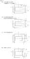
- FIG. 3 shows the basic concept of the present invention
- A shows a conventional art showing Comparative Example 1
- B shows a conventional art showing Comparative Example 2
- C shows the first embodiment
- D shows a modification.
- the configuration of seat belt retractor 1 is conceptualized.
- the seat belt retractor 1' according to a conventional art (Comparative Example 1) shown in Fig. 3 (A) is described, for example, in Patent Literature 1.
- a locking mechanism 6' is disposed on one side of a base frame 3', and a pretensioner 5' and a spring unit 4' are disposed on the opposite side.
- This seat belt retractor 1' is configured such that an engaging pawl (not shown) of the locking mechanism 6' engages with internal teeth (not shown) of an opening formed in an end face 32' of the base frame 3', and therefore a spool 2' cannot be borne by the opening of the base frame 3'.
- a bearing component 50' (for example, a pretensioner plate) is disposed between the base frame 3' and the pretensioner 5'.
- the seat belt retractor 1' according to a conventional art (Comparative Example 2) shown in Fig. 3 (B) is described, for example, in Patent Literature 2.
- a spring unit 4' is disposed on one side of a base frame 3', and a pretensioner 5' and a locking mechanism 6' are disposed on the opposite side.
- this seat belt retractor 1' is also configured such that an engaging pawl (not shown) of the locking mechanism 6' engages with internal teeth (not shown) of an opening formed in an end face 32' of the base frame 3', and therefore a spool 2' cannot be borne by the opening of the base frame 3'.
- a bearing component 50' (for example, a bearing ring) is disposed between the base frame 3' and the pretensioner 5'.
- the seat belt retractor 1 according to the first embodiment shown in Fig. 3 (C) is shown in Fig. 1 and Fig. 2 .
- a pretensioner 5 is disposed on the inner side of one side of a base frame 3
- a locking mechanism 6 is disposed on the outer side of the one side
- a spring unit 4 is disposed on the opposite side.
- this seat belt retractor 1 is configured such that an engaging pawl 61 of the locking mechanism 6 engages with internal teeth of an opening 32a formed in an end face 32 of the base frame 3, and therefore a spool 2 cannot be borne by the opening 32a of the base frame 3.
- the pretensioner 5 is disposed inside the base frame 3, and the spool 2 is borne by an opening 53a formed in a cover member 53.
- the arrangement of the spring unit 4 and the locking mechanism 6 shown in Fig. 3 (C) is reversed.
- a locking mechanism 6 that stops the withdrawal of the webbing in an emergency or a spring unit 4 that biases the spool 2 in the retracting direction may be disposed on the outer side of the end face 32 of the base frame 3 on which the cover member 53 is disposed.
- the arrangement of the spring unit 4 and the locking mechanism 6 is arbitrarily set according to the configuration of the seat belt retractor 1.
- the configuration of the seat belt retractor 1 shown in Fig. 3 (A) to (D) is a conceptual diagram in which the structure is simplified.
- the lock gear and the pawl of the locking mechanism 6, 6' may be separately disposed on both sides of the base frame 3.
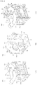
- Fig. 4 shows the frame body, (A) shows a front perspective view, (B) shows a back perspective view, and (C) shows a modification.
- Metal components such as the base frame 3 and the guide pipe 52b of the pretensioner 5 described above may be coated with an anticorrosion coating from the viewpoint of preventing corrosion.
- a cover member is disposed outside the base frame 3'. Therefore, the cover member needs to be fixed to the base frame 3' after assembling the components of the pretensioner 5'. Therefore, metal components such as the base frame 3', the guide pipe, and the cover member need to be coated by separately impregnating them with anticorrosion paint.
- the cover member 53 is disposed inside the base frame 3, after forming a frame body 100 in which the guide pipe 52b and the cover member 53 are fixed to the base frame 3, other components can be assembled through the opening 32a formed in the end face 32 of the base frame 3. Therefore, after forming the frame body 100, the frame body 100 can be coated with an anticorrosion coating by impregnating it with anticorrosion paint, a plurality of components can be anticorrosion-treated at once, the number of steps of anticorrosion treatment can be reduced, and the burden of treatment work can be reduced.
- the cover member 53 since the cover member 53 is disposed inside the base frame 3, the cover member 53 can be connected to both the end face 32 and the side face 33 of the base frame 3, and the cover member 53 can be fixed firmly.
- a plurality of protrusions 53c are formed on the outer periphery of the cover member 53, and the cover member 53 can be fixed to the base frame 3 by passing the protrusions 53c through openings formed in the end face 32 and the side face 33 of the base frame 3 or disposing the protrusions 53c along the edge portions and then swaging and bending the protrusions 53c as necessary.
- the protrusions 53c of the cover member 53 may be passed through a passing portion 3a formed in the side face 33 of the base frame 3 or a through portion 3b formed in the end face 32.
- the passing portion 3a is formed by a bridge portion formed by causing part of the side face 33 of the base frame 3 to protrude inward.
- the passed protrusions 53c may or may not be bent.
- the arrangement of the protrusions 53c is not limited to the shown configuration, and the protrusions 53c are arbitrarily disposed according to the shapes of the base frame 3 and the cover member 53.
- Fig. 5 is a sectional view showing the seat belt retractor according to the second embodiment of the present invention.
- This sectional view is the same sectional view as the B-B cross-sectional view shown in Fig. 2 (B) .
- the same reference signs will be used to designate the same components as those of the seat belt retractor 1 according to the first embodiment described above, and redundant description will be omitted.
- the seat belt retractor 1 according to the second embodiment shown in the figure is the same in the arrangement of the base frame 3, the spring unit 4, the pretensioner 5, and the locking mechanism 6 as the seat belt retractor 1 according to the first embodiment described above.
- the cover member 53 in the second embodiment is the same in the basic configuration as the first embodiment described above, but does not have the bent portion 53b in the opening 53a. Whether the bent portion 53b is formed in the opening 53a or not can be arbitrarily set.
- a guide member 54 that guides the movement of the projectile 52a discharged into the cover member 53 is disposed.
- the guide member 54 is formed such that the projectile 52a is moved along the outline of the cover member 53. Therefore, owing to such a guide member 54, the discharged projectile 52a does not interfere with the rotor 51 (regardless of whether or not the rotor 51 is formed integrally with the locking base 22), and the driving of the rotor 51 can be stabilized.
- the guide member 54 may have a shape externally fitted on the deformation plate 24.
- the radial load of the spool 2 may be supported indirectly by supporting the outer peripheral part of the guide member 54 with the opening 53a of the cover member 53 as shown in the figure.
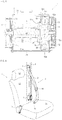
- Fig. 6 is an overall configuration diagram showing the seat belt apparatus according to an embodiment of the present invention.
- components other than the seat belt apparatus are shown by alternate long and short dash line.
- the seat belt apparatus 10 includes a webbing W that restrains an occupant, a seat belt retractor 1 that retracts the webbing W, a guide anchor 11 that is provided on the vehicle body side and that guides the webbing W, a belt anchor 12 that fixes the webbing W to the vehicle body, a buckle 13 disposed on a side face of a seat S, and a tongue 14 disposed on the webbing W.
- the seat belt retractor 1 includes, as shown in Fig.
- a spool 2 that retracts the webbing W
- a base frame 3 that rotatably houses the spool 2
- a spring unit 4 that biases the spool 2 in the retracting direction
- a pretensioner 5 that retracts the webbing W to take up the slack therein in an emergency
- a locking mechanism 6 that stops the withdrawal of the webbing W in an emergency.
- the seat S includes, for example, a seat portion S1 in which the occupant is seated, a backrest portion S2 located behind the occupant, and a headrest portion S3 that supports the head of the occupant.
- the seat belt retractor 1 is housed, for example, in a B-pillar P of the vehicle body.
- the buckle 13 is often disposed on a side face of the seat portion S1
- the belt anchor 12 is often disposed on the lower face of the seat portion S1.
- the guide anchor 11 is often disposed on the B-pillar P.
- One end of the webbing W is connected to the belt anchor 12, and the other end thereof is connected through the guide anchor 11 to the seat belt retractor 1.
- the webbing W is withdrawn from the seat belt retractor 1 while sliding through a passing hole of the guide anchor 11.
- the webbing W is retracted by the action of the spring unit 4 of the seat belt retractor 1 until a predetermined load is applied.
- the seat belt apparatus 10 described above is obtained by applying the seat belt retractor 1 according to this embodiment described above to an ordinary seat belt apparatus in a front seat. Therefore, also in the seat belt apparatus 10 according to this embodiment, the number of components and the size of the seat belt retractor 1 can be reduced.
- the seat belt apparatus 10 is not limited to the application to a front seat. For example, it can be easily applied also to a rear seat, with the guide anchor 11 omitted.
- the present invention is not limited to the above-described embodiments, and may be applied to seat belt apparatuses used in transportation means other than vehicles.
Description
- The present invention relates to a seat belt retractor and a seat belt apparatus, and more specifically, to a seat belt retractor suitable for the reduction in the number of components, size, and weight, and a seat belt apparatus having the seat belt retractor.
US2012/0049500 A1 is the closest prior art document and discloses the preamble ofclaim 1. - Vehicles such as automobiles are generally provided with a seat belt apparatus that restrains an occupant in a seat including a seat portion in which the occupant is seated and a backrest portion located behind the occupant. Such a seat belt apparatus includes a webbing that restrains an occupant, a seat belt retractor that retracts the webbing, a guide anchor that is provided on the vehicle body side and that guides the webbing, a belt anchor that fixes the webbing to the vehicle body, a buckle disposed on the side of the seat, and a tongue disposed on the webbing, and restrains the occupant in the seat with the webbing by fitting the tongue into the buckle. In such a seat belt apparatus, one end of the webbing is fixed to the belt anchor, and the other end of the webbing is passed through the guide anchor and is connected to the seat belt retractor.
- It is becoming common that such a seat belt retractor includes a locking mechanism that stops the withdrawal of the webbing when the vehicle is inclined or rapidly decreased in speeds in a vehicle collision or the like, and a pretensioner that takes up the slack in the webbing in a vehicle collision or the like (see, for example,
Patent Literature 1 and Patent Literature 2). - In the seat belt retractor described in
Patent Literature 1, a locking mechanism (4, 5) is disposed on one outer side (1A) of a base frame (1), a pretensioner (10) including driving means (11, 12, 15) and the like is disposed on the other outer side (1B) of the base frame (1), and a spring unit (8) is disposed on the outer side thereof. A pretensioner plate (31) for rotatably supporting a spool is disposed between the base frame and the pretensioner. - In the seat belt retractor described in
Patent Literature 2, a spring unit is disposed on one outer side of a base frame (8), a pretensioner including a drive unit (7) is disposed on the other outer side of the base frame (8), and a locking mechanism including a pawl (4) and a control unit (10) is disposed on the outer side thereof. A bearing ring (13) for rotatably supporting a spool is disposed between the base frame and the pretensioner. -
- Patent Literature 1: Japanese Unexamined Patent Application Publication No.
2002-145012 - Patent Literature 2: Japanese Unexamined Patent Application Publication
(Translation of PCT Application) No. 2012-509808 - As described in
Patent Literature 1 andPatent Literature 2, the seat belt retractor has a complex mechanism and a large number of components, and therefore there is a problem in that cost reduction is difficult. Because the above-described seat belt retractor is a component disposed in a small space of a vehicle body, reduction in size and weight is desired. However, as described inPatent Literature 1 andPatent Literature 2, the spring unit, locking mechanism, and pretensioner are disposed on both sides of the base frame, and therefore there is a problem in that reduction in size and weight is difficult. - The present invention is made in view of such problems, and it is an object of the present invention to provide a seat belt retractor and a seat belt apparatus the number of components of which can be reduced and the size and weight of which can be reduced.
- The present invention provides a seat belt retractor including a spool that retracts a webbing that restrains an occupant, a base frame that rotatably houses the spool, and a pretensioner that retracts the webbing to take up the slack therein in an emergency, wherein the pretensioner includes a rotor that is connected coaxially with the spool and that has a plurality of engaging teeth formed on the outer periphery thereof, a power generating means that engages with the engaging teeth and rotates the rotor, and a cover member that houses at least the rotor, and the cover member is disposed inside the base frame.
- The present invention provides a seat belt apparatus including a webbing that restrains an occupant, a seat belt retractor that retracts the webbing, a belt anchor that fixes the webbing to a vehicle body, a buckle disposed on a side face of a seat, and a tongue disposed on the webbing, wherein the seat belt retractor includes a spool that retracts the webbing, a base frame that rotatably houses the spool, and a pretensioner that retracts the webbing to take up the slack therein in an emergency, the pretensioner includes a rotor that is connected coaxially with the spool and that has a plurality of engaging teeth formed on the outer periphery thereof, a power generating means that engages with the engaging teeth and rotates the rotor, and a cover member that houses at least the rotor, and the cover member is disposed inside the base frame.
- In the above-described seat belt retractor and seat belt apparatus, the cover member may be able to bear the spool directly or indirectly. The cover member may have an opening through which an end of the spool can be passed, and may be configured to support the radial load of the spool with the inner edge of the opening.
- A locking mechanism that stops the withdrawal of the webbing in an emergency or a spring unit that biases the spool in the retracting direction may be disposed outside the base frame in which the cover member is disposed.
- The power generating means may include an projectile that engages with the engaging teeth and rotates the rotor, a guide pipe that houses the projectile and guides the driving, and a gas generator that is disposed at an end of the guide pipe and that imparts power to the projectile. After forming a frame body in which the guide pipe and the cover member are fixed to the base frame, other components may be assembled.
- According to the seat belt retractor and seat belt apparatus of the present invention described above, since the cover member of the pretensioner is disposed inside the base frame, the opening of the cover member can be used as a bearing for the spool or as part of the locking mechanism, a pretensioner plate and a bearing ring that are conventionally disposed separately from the cover member can be omitted, and the number of components can be reduced. In addition, since the pretensioner is disposed inside the base frame, the degree of freedom in designing the locking mechanism and the pretensioner can be improved, an optimum arrangement can be achieved, and the size and weight of the seat belt retractor can be reduced.
-
-
Fig. 1 is an exploded view showing a seat belt retractor according to a first embodiment of the present invention. -
Fig. 2 shows the seat belt retractor shown inFig. 1 , (A) is a perspective view, and (B) is a cross-sectional view taken along line B-B ofFig. 2 (A) . -
Fig. 3 shows the basic concept of the present invention, (A) shows a conventional art showing Comparative Example 1, (B) shows a conventional art showing Comparative Example 2, (C) shows the first embodiment, and (D) shows a modification. -
Fig. 4 shows a frame body, (A) shows a front perspective view, (B) shows a back perspective view, and (C) shows a modification. -
Fig. 5 is a sectional view showing a seat belt retractor according to a second embodiment of the present invention. -
Fig. 6 is an overall configuration diagram showing a seat belt apparatus according to an embodiment of the present invention. - Embodiments of the present invention will now be described with reference to
Fig. 1 to Fig. 6 . Here,Fig. 1 is an exploded view showing a seat belt retractor according to a first embodiment of the present invention.Fig. 2 shows the seat belt retractor shown inFig. 1 , (A) is a perspective view, and (B) is a cross-sectional view taken along line B-B ofFig. 2 (A) . - The
seat belt retractor 1 according to the first embodiment of the present invention includes, as shown inFig. 1 andFig. 2 , aspool 2 that retracts a webbing that restrains an occupant, abase frame 3 that rotatably houses thespool 2, aspring unit 4 that biases thespool 2 in the retracting direction, apretensioner 5 that retracts the webbing to take up the slack therein in an emergency, and alocking mechanism 6 that stops the withdrawal of the webbing in an emergency. Thepretensioner 5 has arotor 51 that is connected coaxially with thespool 2 and that has a plurality ofengaging teeth 51a formed on the outer periphery thereof, a power generating means 52 that engages with theengaging teeth 51a and rotates therotor 51, and acover member 53 that houses at least therotor 51. Thecover member 53 is disposed inside thebase frame 3 and can bear thespool 2. In each figure, the depiction of the webbing is omitted. - The
spool 2 is a winding drum that retracts the webbing. One end of thespool 2 is connected to thespring unit 4. Thespool 2 is biased in the direction of retracting the webbing by a spiral spring housed in thespring unit 4. The means for imparting a retracting force to thespool 2 is not limited to thespring unit 4, and may be another means employing an electric motor or the like. - A
torsion bar 21 forming a central shaft is passed through a cavity formed in the central part of thespool 2. One end of thetorsion bar 21 is connected to the inner surface of the end of thespool 2 to which thespring unit 4 is connected. The other end of thetorsion bar 21 is connected to alocking base 22. The configuration of the impact absorption mechanism including thetorsion bar 21 is not limited to the shown configuration. For example, one end of thetorsion bar 21 may be connected to thespring unit 4 through thespool 2. The configuration of the impact absorption mechanism including thetorsion bar 21 may be omitted when unnecessary. - One end of the
locking base 22 is passed through the cavity of thespool 2, and the other end of thelocking base 22 is rotatably supported by aretainer cover 35. A shaft portion on which therotor 51 and adeformation plate 24 described later are fitted is formed at one end of thelocking base 22, and anengaging pawl 61 of thelocking mechanism 6 is rotatably disposed at the other end of thelocking base 22. - Therefore, at normal time when the
pretensioner 5 and thelocking mechanism 6 are not in operation, thetorsion bar 21 rotates integrally with thespool 2. When thepretensioner 5 is in operation, the webbing can be retracted on thespool 2 by rotating thetorsion bar 21. When thelocking mechanism 6 is in operation, the rotation of thetorsion bar 21 is restrained, and the withdrawal of the webbing is suppressed by locking the rotation of thespool 2. - When a force in the withdrawing direction acts on the webbing, because the
spool 2 is cantilever-supported by thetorsion bar 21, the load of the webbing can be limited by the torsional deformation of thetorsion bar 21, and the impact energy of the occupant is absorbed. - A
deformation pin 23 made of metal is inserted into the end face of thespool 2 on the side on which thepretensioner 5 is disposed such that the head thereof is exposed. Adeformation plate 24 having a protrusion engageable with the head of thedeformation pin 23 is fitted on the shaft portion of thelocking base 22. Thedeformation pin 23 and thedeformation plate 24 may be formed integrally with each other. - Therefore, when the
spool 2 is rotated by the webbing being withdrawn with thelocking mechanism 6 in operation, a force that attempts to pluck thedeformation pin 23 in the direction of rotation acts. Thedeformation pin 23 is drawn between an end face of thespool 2 and thedeformation plate 24 and plastically deformed, and absorbs the impact energy of the occupant. - By disposing such a
deformation pin 23 and such adeformation plate 24, the energy absorption capacity can be improved. When thetorsion bar 21 has sufficient energy absorption capacity, thedeformation pin 23 and thedeformation plate 24 may be omitted. - The
base frame 3 is a case that forms the framework of theseat belt retractor 1. Thebase frame 3 includes, for example, a pair of opposed end faces 31 and 32, aside face 33 connecting these end faces, and atie plate 34 opposed to theside face 33 and connected to the end faces 31 and 32. Thespring unit 4 is disposed on the outer side of theend face 31, thepretensioner 5 is disposed on the inner side of theend face 32, and thelocking mechanism 6 is disposed on the outer side of theend face 32. Thelocking mechanism 6 is housed in theretainer cover 35 connected to thebase frame 3. - A vehicle sensor 7 that detects rapid deceleration and inclination of the vehicle body is disposed in the
retainer cover 35. The vehicle sensor 7 has a spherical mass body (not shown) housed therein and anactuator 71 rocked by the movement of the mass body, and is housed in a recess formed in theretainer cover 35. Such a vehicle sensor 7 is configured such that when rapid deceleration or inclination occurs in the vehicle body, the mass body moves upward, and accordingly the tip of theactuator 71 is rocked upward. By this rocking, theactuator 71 is engaged withexternal teeth 62a of alock gear 62 described later. The vehicle sensor 7 may also be configured to transmit a detection signal to other electronic components and an electric control system mounted on the vehicle when rapid deceleration or inclination of the vehicle body is detected. - The
pretensioner 5 includes arotor 51 that is connected to the end of thespool 2 with thetorsion bar 21 and the lockingbase 22 therebetween, a power generating means 52 that rotates therotor 51, and acover member 53 that houses therotor 51. Therotor 51 has a plurality of engagingteeth 51a formed so as to protrude radially outward. - The power generating means 52 includes, for example, an projectile 52a that engages with the engaging
teeth 51a and rotates therotor 51, aguide pipe 52b that houses the projectile 52a and guides the driving, and agas generator 52c that is disposed at an end of theguide pipe 52b and that imparts power to the projectile 52a. - The projectile 52a is, for example, a rod made of synthetic resin, and is configured such that when pressure is applied to the end of the projectile 52a, the projectile 52a moves in the
guide pipe 52b while plastically deforming along the shape of theguide pipe 52b. The projectile 52a is set to such a length that the back end of the projectile 52a is not discharged from theguide pipe 52b when the operation of thepretensioner 5 is completed. Owing to such a configuration, discharge of gas from theguide pipe 52b to the outside after the operation of thepretensioner 5 is completed can be suppressed. The projectile 52a is not limited to a rod member, and may be, for example, a plurality of spheres made of metal or synthetic resin, or a plurality of twin balls that are each formed by connecting two spheres made of metal or synthetic resin. - The front end of the
guide pipe 52b is disposed at a position facing the engagingteeth 51a of therotor 51. The back end of theguide pipe 52b is extended by a length necessary for the movement of the projectile 52a, and is disposed along the outline of theseat belt retractor 1. Acutout 52d is formed in part of the outer periphery of the front end of theguide pipe 52b so that the engagingteeth 51a of therotor 51 can rotate from thiscutout 52d through the inside of theguide pipe 52b. - The
gas generator 52c is, for example, a micro gas generator that jets gas into theguide pipe 52b in response to a detection signal from the vehicle sensor 7 or an acceleration sensor mounted in the vehicle body. A piston (not shown) that seals the gap between the projectile 52a and the peripheral surface of theguide pipe 52b and forms a pressure receiving surface may be disposed between thegas generator 52c and the projectile 52a. - According to such a power generating means 52, at normal time, a state where the projectile 52a is housed in the
guide pipe 52b is maintained by the rigidity of the projectile 52a. When gas is generated from thegas generator 52c, the projectile 52a moves in theguide pipe 52b while plastically deforming, and is discharged from the front end of theguide pipe 52b into thecover member 53. At this time, the projectile 52a engages with the engagingteeth 51a of therotor 51 while plastically deforming, and rotates the engagingteeth 51a in the direction of the arrow in the figure. The projectile 52a moves along the outline of thecover member 53, finally, comes into contact with theguide pipe 52b, the projectile 52a itself, thecover member 53, or another component and stops. - The
cover member 53 is a metal component having a substantially bowl shape or a substantially box shape, and is fixed to the inner sides of theend face 32 and theside face 33 of thebase frame 3. As shown inFig. 1 andFig. 2 (B) , thecover member 53 has anopening 53a through which the end of thespool 2 can be passed, and is configured to support the radial load of thespool 2 with the inner edge of theopening 53a indirectly with thedeformation plate 24 therebetween, and theopening 53a forms a bearing for thespool 2. In this embodiment, abent portion 53b is formed by bending the inner edge of theopening 53a toward theend face 32, and a bearing is formed by thisbent portion 53b. - When the
deformation plate 24 is omitted, a bearing may be formed such that the radial load of thespool 2 is supported directly by the inner edge of theopening 53a of thecover member 53, or thespool 2 may be borne with a component other than thedeformation plate 24 therebetween. Thebent portion 53b may also be formed by bending the inner edge of theopening 53a toward theend face 31. - Because the end of the
spool 2 is rotatably supported also by theretainer cover 35, a minor load bearing can be formed by theretainer cover 35, and a major load bearing can be formed by thecover member 53. The thrust load of thespool 2 may be supported by theretainer cover 35, or may be supported by thecover member 53. - The
locking mechanism 6 includes an engaging pawl 61 (pawl) rockably disposed on the end face of the lockingbase 22, alock gear 62 that rotates the engagingpawl 61 inward, and aflywheel 63 disposed in a space formed between thelock gear 62 and theretainer cover 35. Anopening 32a through which thelocking base 22 can be passed is formed in theend face 32 of thebase frame 3, and internal teeth are formed on the inner edge of theopening 32a. The engagingpawl 61 is disposed engageably with the internal teeth of theopening 32a. - The
lock gear 62 is fitted on a shaft portion of the lockingbase 22 that is supported by theretainer cover 35, andexternal teeth 62a are formed on the outer periphery of thelock gear 62. Theactuator 71 of the vehicle sensor 7 is engaged with theexternal teeth 62a. Theflywheel 63 is rockably disposed on the outer side of thelock gear 62. A circular recess is formed in theretainer cover 35, andinternal teeth 35a are formed inside this recess. The tip of theflywheel 63 is engaged with theinternal teeth 35a. The tip of theflywheel 63 is biased by a spring (not shown) away from theinternal teeth 35a. - A
cam hole 62b that is formed so as to curve from the outer edge side toward the inner edge side is formed in the flat portion of thelock gear 62. A pin (not shown) formed on a side face of the engagingpawl 61 is passed through thecam hole 62b. This pin moves along thecam hole 62b with the rotation of thelock gear 62, and the engagingpawl 61 is rocked. The tip of the engagingpawl 61 may be biased by a spring (not shown) away from the internal teeth of theopening 32a. - The
flywheel 63 is a mass body rockably disposed between theretainer cover 35 and thelock gear 62. The biasing force of the flywheel 63 (the elastic force of the spring) is set larger than the inertial force generated in theflywheel 63 when the withdrawal acceleration of the webbing does not exceed a predetermined threshold. In this case, theflywheel 63 rotates together with thelock gear 62. - On the other hand, when the withdrawal acceleration of the webbing exceeds the predetermined threshold, the inertial force generated in the
flywheel 63 is larger than the biasing force (the elastic force of the spring), and the tip of theflywheel 63 approaches and engages with theinternal teeth 35a of theretainer cover 35. - According to the
locking mechanism 6 having such a configuration, at normal time, theactuator 71, theflywheel 63, and the engagingpawl 61 are not engaged with each other, and therefore the lockingbase 22 and thelock gear 62 rotate with the rotation of thespool 2. - When the webbing is faster than a normal withdrawal acceleration, that is, when the withdrawal acceleration of the webbing exceeds the predetermined threshold, the
flywheel 63 rocks and engages with theinternal teeth 35a of theretainer cover 35, and the rotation of thelock gear 62 is restrained. On the other hand, the lockingbase 22 attempts to continue to rotate, therefore relative rotation occurs between the lockingbase 22 and thelock gear 62, accordingly the engagingpawl 61 moves along thecam hole 62b, and the tip of the engagingpawl 61 engages with the internal teeth formed on the inner edge of theopening 32a of thebase frame 3. As a result, the rotation of the lockingbase 22 is restrained. - In the above-described embodiment, the description has been given of the case where the engaging
pawl 61 is engaged with thebase frame 3. However, internal teeth engageable with the engagingpawl 61 may be formed in theopening 53a of thecover member 53, and thespool 2 may be borne by theopening 32a of thebase frame 3. - When the vehicle sensor 7 detects rapid deceleration or inclination of the vehicle body, the
actuator 71 engages with theexternal teeth 62a of thelock gear 62, and the rotation of thelock gear 62 is restrained. When the webbing is going to be withdrawn in that state, relative rotation occurs between the lockingbase 22 and thelock gear 62, accordingly the engagingpawl 61 moves along thecam hole 62b, and the tip of the engagingpawl 61 engages with the internal teeth formed on the inner edge of theopening 32a of thebase frame 3. As a result, the rotation of the lockingbase 22 is restrained. - According to the
seat belt retractor 1 of the first embodiment described above, thecover member 53 of thepretensioner 5 is disposed inside thebase frame 3, therefore the side face of thebase frame 3 can be used as a bearing for thespool 2, a pretensioner plate and a bearing ring that are conventionally disposed separately from thecover member 53 can be omitted, and the number of components can be reduced. In addition, since thepretensioner 5 is disposed inside thebase frame 3, the number of components disposed outside thebase frame 3 can be reduced, and the size of theseat belt retractor 1 can be reduced. - Here,
Fig. 3 shows the basic concept of the present invention, (A) shows a conventional art showing Comparative Example 1, (B) shows a conventional art showing Comparative Example 2, (C) shows the first embodiment, and (D) shows a modification. In each figure, the configuration ofseat belt retractor 1 is conceptualized. - The seat belt retractor 1' according to a conventional art (Comparative Example 1) shown in
Fig. 3 (A) is described, for example, inPatent Literature 1. In such a seat belt retractor 1', a locking mechanism 6' is disposed on one side of a base frame 3', and a pretensioner 5' and a spring unit 4' are disposed on the opposite side. This seat belt retractor 1' is configured such that an engaging pawl (not shown) of the locking mechanism 6' engages with internal teeth (not shown) of an opening formed in anend face 32' of the base frame 3', and therefore a spool 2' cannot be borne by the opening of the base frame 3'. So, a bearing component 50' (for example, a pretensioner plate) is disposed between the base frame 3' and the pretensioner 5'. - The seat belt retractor 1' according to a conventional art (Comparative Example 2) shown in
Fig. 3 (B) is described, for example, inPatent Literature 2. In such a seat belt retractor 1', a spring unit 4' is disposed on one side of a base frame 3', and a pretensioner 5' and a locking mechanism 6' are disposed on the opposite side. As with Comparative Example 1, this seat belt retractor 1' is also configured such that an engaging pawl (not shown) of the locking mechanism 6' engages with internal teeth (not shown) of an opening formed in anend face 32' of the base frame 3', and therefore a spool 2' cannot be borne by the opening of the base frame 3'. So, a bearing component 50' (for example, a bearing ring) is disposed between the base frame 3' and the pretensioner 5'. - The
seat belt retractor 1 according to the first embodiment shown inFig. 3 (C) is shown inFig. 1 andFig. 2 . In such aseat belt retractor 1, apretensioner 5 is disposed on the inner side of one side of abase frame 3, alocking mechanism 6 is disposed on the outer side of the one side, and aspring unit 4 is disposed on the opposite side. As shown inFig. 1 andFig. 2(B) , as with the conventional arts, thisseat belt retractor 1 is configured such that an engagingpawl 61 of thelocking mechanism 6 engages with internal teeth of anopening 32a formed in anend face 32 of thebase frame 3, and therefore aspool 2 cannot be borne by theopening 32a of thebase frame 3. So, in this embodiment, thepretensioner 5 is disposed inside thebase frame 3, and thespool 2 is borne by anopening 53a formed in acover member 53. - In the
seat belt retractor 1 according to a modification of the first embodiment shown inFig. 3 (D) , the arrangement of thespring unit 4 and thelocking mechanism 6 shown inFig. 3 (C) is reversed. As described above, alocking mechanism 6 that stops the withdrawal of the webbing in an emergency or aspring unit 4 that biases thespool 2 in the retracting direction may be disposed on the outer side of theend face 32 of thebase frame 3 on which thecover member 53 is disposed. The arrangement of thespring unit 4 and thelocking mechanism 6 is arbitrarily set according to the configuration of theseat belt retractor 1. - The configuration of the
seat belt retractor 1 shown inFig. 3 (A) to (D) is a conceptual diagram in which the structure is simplified. For example, the lock gear and the pawl of thelocking mechanism 6, 6' may be separately disposed on both sides of thebase frame 3. - Next, the configuration of a
frame body 100 forming the framework of theseat belt retractor 1 will be described with reference toFigs. 4 (A) and (B) . Here,Fig. 4 shows the frame body, (A) shows a front perspective view, (B) shows a back perspective view, and (C) shows a modification. - Metal components such as the
base frame 3 and theguide pipe 52b of thepretensioner 5 described above may be coated with an anticorrosion coating from the viewpoint of preventing corrosion. In the conventional seat belt retractors 1' shown inFigs. 3 (A) and (B) , a cover member is disposed outside the base frame 3'. Therefore, the cover member needs to be fixed to the base frame 3' after assembling the components of the pretensioner 5'. Therefore, metal components such as the base frame 3', the guide pipe, and the cover member need to be coated by separately impregnating them with anticorrosion paint. - In contrast, in the
seat belt retractor 1 according to the first embodiment, since thecover member 53 is disposed inside thebase frame 3, after forming aframe body 100 in which theguide pipe 52b and thecover member 53 are fixed to thebase frame 3, other components can be assembled through theopening 32a formed in theend face 32 of thebase frame 3. Therefore, after forming theframe body 100, theframe body 100 can be coated with an anticorrosion coating by impregnating it with anticorrosion paint, a plurality of components can be anticorrosion-treated at once, the number of steps of anticorrosion treatment can be reduced, and the burden of treatment work can be reduced. - In the conventional seat belt retractors 1' shown in
Figs. 3 (A) and (B) , since the pretensioner 5' is disposed outside the base frame 3', a cover member has to be fixed to theend face 32 of the base frame 3'. - In contrast, in the
seat belt retractor 1 according to the first embodiment, since thecover member 53 is disposed inside thebase frame 3, thecover member 53 can be connected to both theend face 32 and theside face 33 of thebase frame 3, and thecover member 53 can be fixed firmly. For example, as shown inFig. 4 (B) , a plurality ofprotrusions 53c are formed on the outer periphery of thecover member 53, and thecover member 53 can be fixed to thebase frame 3 by passing theprotrusions 53c through openings formed in theend face 32 and theside face 33 of thebase frame 3 or disposing theprotrusions 53c along the edge portions and then swaging and bending theprotrusions 53c as necessary. - Alternatively, as in the modification shown
Fig. 4 (C) , theprotrusions 53c of thecover member 53 may be passed through a passingportion 3a formed in theside face 33 of thebase frame 3 or a throughportion 3b formed in theend face 32. The passingportion 3a is formed by a bridge portion formed by causing part of theside face 33 of thebase frame 3 to protrude inward. The passedprotrusions 53c may or may not be bent. The arrangement of theprotrusions 53c is not limited to the shown configuration, and theprotrusions 53c are arbitrarily disposed according to the shapes of thebase frame 3 and thecover member 53. - Next, a
seat belt retractor 1 according to a second embodiment of the present invention will be described with reference toFig. 5 . Here,Fig. 5 is a sectional view showing the seat belt retractor according to the second embodiment of the present invention. This sectional view is the same sectional view as the B-B cross-sectional view shown inFig. 2 (B) . The same reference signs will be used to designate the same components as those of theseat belt retractor 1 according to the first embodiment described above, and redundant description will be omitted. - The
seat belt retractor 1 according to the second embodiment shown in the figure is the same in the arrangement of thebase frame 3, thespring unit 4, thepretensioner 5, and thelocking mechanism 6 as theseat belt retractor 1 according to the first embodiment described above. Thecover member 53 in the second embodiment is the same in the basic configuration as the first embodiment described above, but does not have thebent portion 53b in theopening 53a. Whether thebent portion 53b is formed in theopening 53a or not can be arbitrarily set. - In the
pretensioner 5 in the second embodiment, aguide member 54 that guides the movement of the projectile 52a discharged into thecover member 53 is disposed. Theguide member 54 is formed such that the projectile 52a is moved along the outline of thecover member 53. Therefore, owing to such aguide member 54, the discharged projectile 52a does not interfere with the rotor 51 (regardless of whether or not therotor 51 is formed integrally with the locking base 22), and the driving of therotor 51 can be stabilized. - The
guide member 54 may have a shape externally fitted on thedeformation plate 24. In this case, the radial load of thespool 2 may be supported indirectly by supporting the outer peripheral part of theguide member 54 with theopening 53a of thecover member 53 as shown in the figure. - Next, a seat belt apparatus according to an embodiment of the present invention will be described with reference to
Fig. 6 . Here,Fig. 6 is an overall configuration diagram showing the seat belt apparatus according to an embodiment of the present invention. InFig. 6 , for the convenience of illustration, components other than the seat belt apparatus are shown by alternate long and short dash line. - The
seat belt apparatus 10 according to this embodiment shown inFig. 6 includes a webbing W that restrains an occupant, aseat belt retractor 1 that retracts the webbing W, aguide anchor 11 that is provided on the vehicle body side and that guides the webbing W, abelt anchor 12 that fixes the webbing W to the vehicle body, abuckle 13 disposed on a side face of a seat S, and atongue 14 disposed on the webbing W. Theseat belt retractor 1 includes, as shown inFig. 1 , aspool 2 that retracts the webbing W, abase frame 3 that rotatably houses thespool 2, aspring unit 4 that biases thespool 2 in the retracting direction, apretensioner 5 that retracts the webbing W to take up the slack therein in an emergency, and alocking mechanism 6 that stops the withdrawal of the webbing W in an emergency. Because such aseat belt retractor 1 has the same configuration as that shown inFig. 1 to Fig. 2 (B) , the detailed description thereof will be omitted here. - The seat S includes, for example, a seat portion S1 in which the occupant is seated, a backrest portion S2 located behind the occupant, and a headrest portion S3 that supports the head of the occupant. The
seat belt retractor 1 is housed, for example, in a B-pillar P of the vehicle body. In general, thebuckle 13 is often disposed on a side face of the seat portion S1, and thebelt anchor 12 is often disposed on the lower face of the seat portion S1. Theguide anchor 11 is often disposed on the B-pillar P. One end of the webbing W is connected to thebelt anchor 12, and the other end thereof is connected through theguide anchor 11 to theseat belt retractor 1. - Therefore, when fitting the
tongue 14 into thebuckle 13, the webbing W is withdrawn from theseat belt retractor 1 while sliding through a passing hole of theguide anchor 11. When the occupant fastens the seat belt or when the occupant unfastens the seat belt when the occupant gets out the vehicle, the webbing W is retracted by the action of thespring unit 4 of theseat belt retractor 1 until a predetermined load is applied. - The
seat belt apparatus 10 described above is obtained by applying theseat belt retractor 1 according to this embodiment described above to an ordinary seat belt apparatus in a front seat. Therefore, also in theseat belt apparatus 10 according to this embodiment, the number of components and the size of theseat belt retractor 1 can be reduced. Theseat belt apparatus 10 is not limited to the application to a front seat. For example, it can be easily applied also to a rear seat, with theguide anchor 11 omitted. - Of course, the present invention is not limited to the above-described embodiments, and may be applied to seat belt apparatuses used in transportation means other than vehicles.
Claims (6)
- A seat belt retractor (1) comprising: a spool (2) that retracts a webbing (W) that restrains an occupant; a base frame (3) that rotatably houses the spool (2); and a pretensioner (5) that retracts the webbing (W) to take up the slack therein in an emergency,
wherein the pretensioner (5) includes a rotor (51) that is connected coaxially with the spool (2) and that has a plurality of engaging teeth (51a) formed on the outer periphery thereof, a power generating means (52) that is capable of ejecting a projectile (52a) that engages with the engaging teeth (51a) and rotates the rotor (51), and a cover member (53) that provides for an outline along which the projectile (52a) may be moved,
wherein the base frame (3) includes a first end (31) and a second end face (32) opposing to each other, and a side face (33) connecting the first end face (31) and the second end face (32), and
wherein the cover member (53) at least houses the rotor (51),
characterized in that
the cover member (53), which is disposed inside the base frame (3), is disposed between the first end face (31) and the second end face (32). - The seat belt retractor (1) according to Claim 1, wherein the cover member (53) can bear the spool (2) directly or indirectly.
- The seat belt retractor (1) according to Claim 2, wherein the cover member (53) has an opening (53a) through / which an end of the spool (2) can be passed, and is configured to support the radial load of the spool (2) with the inner edge of the opening (53a).
- The seat belt retractor (1) according to any one of Claims 1 to 3, wherein a locking mechanism (6) that stops the withdrawal of the webbing (W) in an emergency or a spring unit (4) that biases the spool (2) in the retracting direction is disposed outside the base frame (3) in which the cover member (53) is disposed.
- The seat belt retractor (1) according to any one of Claims 1 to 4, wherein the power generating means (52) includes an projectile (52a) that engages with the engaging teeth (51a) and rotates the rotor (51), a guide pipe (52b) that houses the projectile (52a) and guides the driving, and a gas generator (52c) that is disposed at an end of the guide pipe (52b) and that imparts power to the projectile (52a), and wherein after forming a frame body (100) in which the guide pipe (52b) and the cover member (53) are fixed to the base frame (3), other components are assembled.
- A seat belt apparatus (10) comprising: a webbing (W) that restrains an occupant; a seat belt retractor (1) according to any one of Claims 1 to 5; a belt anchor (12) that fixes the webbing (W) to a vehicle body; a buckle (13) disposed on a side face of a seat (S); and a tongue (14) disposed on the webbing (W).
Applications Claiming Priority (2)
| Application Number | Priority Date | Filing Date | Title |
|---|---|---|---|
| JP2013190246A JP6145368B2 (en) | 2013-09-13 | 2013-09-13 | Seat belt retractor and seat belt device |
| PCT/JP2014/073155 WO2015037487A1 (en) | 2013-09-13 | 2014-09-03 | Seat belt retractor and seat belt device |
Publications (3)
| Publication Number | Publication Date |
|---|---|
| EP3045356A1 EP3045356A1 (en) | 2016-07-20 |
| EP3045356A4 EP3045356A4 (en) | 2017-06-14 |
| EP3045356B1 true EP3045356B1 (en) | 2019-08-07 |
Family
ID=52665594
Family Applications (1)
| Application Number | Title | Priority Date | Filing Date |
|---|---|---|---|
| EP14844246.0A Not-in-force EP3045356B1 (en) | 2013-09-13 | 2014-09-03 | Seat belt retractor and seat belt device |
Country Status (5)
| Country | Link |
|---|---|
| US (1) | US10017150B2 (en) |
| EP (1) | EP3045356B1 (en) |
| JP (1) | JP6145368B2 (en) |
| CN (1) | CN105531160B (en) |
| WO (1) | WO2015037487A1 (en) |
Families Citing this family (15)
| Publication number | Priority date | Publication date | Assignee | Title |
|---|---|---|---|---|
| GB201413898D0 (en) * | 2014-08-06 | 2014-09-17 | Moog Controls Ltd | Firing mechanism |
| JP6629038B2 (en) * | 2015-10-21 | 2020-01-15 | Joyson Safety Systems Japan株式会社 | Seat belt retractor and seat belt device |
| DE102016104614B4 (en) | 2016-03-14 | 2018-04-05 | Autoliv Development Ab | Belt retractor with a force limiting device |
| US10315617B2 (en) * | 2016-08-04 | 2019-06-11 | Trw Vehicle Safety Systems Inc. | Seat belt retractor with load limiting stop mechanism |
| JP6732599B2 (en) * | 2016-08-10 | 2020-07-29 | Joyson Safety Systems Japan株式会社 | Pretensioner, retractor and seat belt device |
| DE102016118469A1 (en) | 2016-09-29 | 2018-03-29 | Trw Automotive Gmbh | pretensioners |
| JP6894227B2 (en) * | 2016-12-16 | 2021-06-30 | Joyson Safety Systems Japan株式会社 | Driving wheel manufacturing method |
| JP6539638B2 (en) | 2016-12-19 | 2019-07-03 | 株式会社東海理化電機製作所 | Webbing winding device |
| CN110304013B (en) * | 2018-03-27 | 2021-10-22 | 比亚迪股份有限公司 | Tape winding device and vehicle |
| US10864886B2 (en) * | 2019-02-22 | 2020-12-15 | Autoliv Asp, Inc. | Retractor pretensioner assembly |
| JP6843182B2 (en) * | 2019-06-04 | 2021-03-17 | 株式会社東海理化電機製作所 | Webbing winder |
| CN110329205B (en) * | 2019-07-17 | 2020-10-09 | 重庆光大产业有限公司 | Coiler capable of fixing bent pipe in all directions |
| JP2021091337A (en) * | 2019-12-11 | 2021-06-17 | Joyson Safety Systems Japan株式会社 | Seat belt retractor and seat belt device |
| JP2022078727A (en) | 2020-11-13 | 2022-05-25 | Joyson Safety Systems Japan株式会社 | Seat belt retractor and seat belt device |
| JP2024037090A (en) * | 2022-09-06 | 2024-03-18 | Joyson Safety Systems Japan合同会社 | Retractor and seat belt device |
Citations (1)
| Publication number | Priority date | Publication date | Assignee | Title |
|---|---|---|---|---|
| US20120049500A1 (en) * | 2010-08-31 | 2012-03-01 | Bin Wang | Dual Stage Pretensioning and High Pay-In Capacity Pretensioning Retractor |
Family Cites Families (26)
| Publication number | Priority date | Publication date | Assignee | Title |
|---|---|---|---|---|
| DE2026277C3 (en) * | 1970-05-29 | 1974-07-11 | Ernst Prof. Dipl.-Ing. Dr. Techn. 3300 Braunschweig Fiala | Device for absorbing energy for restraint devices for vehicle occupants, in particular for seat belts |
| US5383623A (en) * | 1992-02-13 | 1995-01-24 | Takata Corporation | Rotary actuator-operated seat belt pretensioner |
| JP2526348B2 (en) * | 1992-05-27 | 1996-08-21 | タカタ株式会社 | Rotator actuator actuation pretensioner |
| JPH0624294A (en) * | 1992-07-08 | 1994-02-01 | Takata Kk | Pretensioner for seat belt device |
| US5485970A (en) * | 1994-03-21 | 1996-01-23 | Trw Vehicle Safety Systems Inc. | Seat belt pretensioner |
| US5881962A (en) * | 1994-04-11 | 1999-03-16 | Autoliv Development Ab | Mass-body drive for a rotary tightening device |
| US5690295A (en) * | 1995-08-02 | 1997-11-25 | Autoliv Development Ab | Mass body drive for a rotational tensioning device |
| US6722600B2 (en) | 1999-02-26 | 2004-04-20 | Takata Corporation | Seat belt retractor |
| DE20003453U1 (en) * | 1999-02-26 | 2000-07-13 | Takata Corp | Tighter |
| JP4707817B2 (en) | 2000-11-06 | 2011-06-22 | タカタ株式会社 | Seat belt retractor and seat belt device |
| US7124974B2 (en) | 1999-02-26 | 2006-10-24 | Takata Corporation | Seat belt retractor |
| JP2001163182A (en) * | 1999-12-13 | 2001-06-19 | Takata Corp | Pretensioner |
| JP2001301567A (en) | 2000-04-24 | 2001-10-31 | Takata Corp | Seat belt winding device |
| JP4654489B2 (en) * | 2000-06-16 | 2011-03-23 | タカタ株式会社 | Seat belt retractor |
| JP2002326558A (en) * | 2001-05-01 | 2002-11-12 | Takata Corp | Control method of seat belt take-up device |
| EP1405777B1 (en) * | 2002-10-03 | 2005-06-29 | Key Safety Systems, Inc. | Retractor |
| JP4295552B2 (en) | 2003-05-16 | 2009-07-15 | 株式会社東海理化電機製作所 | Webbing take-up device |
| KR100979324B1 (en) * | 2004-10-29 | 2010-08-31 | 오토리브 디벨로프먼트 에이비 | Seat belt device |
| JP5444569B2 (en) * | 2008-04-04 | 2014-03-19 | オートリブ ディベロップメント エービー | Seat belt retractor |
| US7988084B2 (en) * | 2008-08-21 | 2011-08-02 | Autoliv Asp, Inc. | Device for pretensioning a seatbelt |
| DE102008059387B4 (en) * | 2008-11-27 | 2018-06-28 | Autoliv Development Ab | Belt retractor with a force limiting device and a tensioning device |
| JP5455597B2 (en) * | 2009-12-15 | 2014-03-26 | タカタ株式会社 | Seat belt retractor and seat belt device provided with the same |
| JP5317945B2 (en) * | 2009-12-15 | 2013-10-16 | タカタ株式会社 | Seat belt retractor and seat belt device provided with the same |
| US8220735B2 (en) * | 2009-12-22 | 2012-07-17 | Autoliv Asp, Inc. | Adaptive load limiting retractor |
| JP5653739B2 (en) * | 2010-12-13 | 2015-01-14 | タカタ株式会社 | Pretensioner, seat belt retractor having the pre tensioner, and seat belt device having the same |
| US9079565B2 (en) * | 2013-03-14 | 2015-07-14 | Autoliv Asp, Inc. | Progressive load limiting restraint system |
-
2013
- 2013-09-13 JP JP2013190246A patent/JP6145368B2/en active Active
-
2014
- 2014-09-03 WO PCT/JP2014/073155 patent/WO2015037487A1/en active Application Filing
- 2014-09-03 US US15/021,488 patent/US10017150B2/en not_active Expired - Fee Related
- 2014-09-03 EP EP14844246.0A patent/EP3045356B1/en not_active Not-in-force
- 2014-09-03 CN CN201480050513.1A patent/CN105531160B/en active Active
Patent Citations (1)
| Publication number | Priority date | Publication date | Assignee | Title |
|---|---|---|---|---|
| US20120049500A1 (en) * | 2010-08-31 | 2012-03-01 | Bin Wang | Dual Stage Pretensioning and High Pay-In Capacity Pretensioning Retractor |
Also Published As
| Publication number | Publication date |
|---|---|
| CN105531160B (en) | 2018-07-06 |
| EP3045356A4 (en) | 2017-06-14 |
| US10017150B2 (en) | 2018-07-10 |
| EP3045356A1 (en) | 2016-07-20 |
| US20160221534A1 (en) | 2016-08-04 |
| CN105531160A (en) | 2016-04-27 |
| JP2015054650A (en) | 2015-03-23 |
| JP6145368B2 (en) | 2017-06-07 |
| WO2015037487A1 (en) | 2015-03-19 |
Similar Documents
| Publication | Publication Date | Title |
|---|---|---|
| EP3045356B1 (en) | Seat belt retractor and seat belt device | |
| WO2015037485A1 (en) | Seat belt retractor, and seat belt device | |
| US9278667B2 (en) | Pretensioner, seat belt retractor, and seat belt device | |
| US9884607B2 (en) | Seat belt retractor and seat belt device | |
| EP3088261B1 (en) | Seat belt retractor and seat belt apparatus | |
| EP3293060B1 (en) | Pretensioner, retractor and seat belt device | |
| US20060243844A1 (en) | Seatbelt retractor | |
| EP1283137B1 (en) | Pretensioner | |
| EP2380788B9 (en) | Seatbelt retractor | |
| JP6629038B2 (en) | Seat belt retractor and seat belt device | |
| US20180178752A1 (en) | Pretensioner, seatbelt retractor, seatbelt device, and method of manufacturing pretensioner | |
| US20200298793A1 (en) | Pretensioner, retractor, and seat belt device | |
| EP1717114A2 (en) | Seatbelt retractor and seatbelt device equipped with the seatbelt retractor | |
| JP6732599B2 (en) | Pretensioner, retractor and seat belt device | |
| JP7265042B2 (en) | Pretensioners, retractors and seatbelt devices | |
| WO2021117605A1 (en) | Seatbelt retractor and seatbelt device | |
| US10046731B2 (en) | Energy absorption apparatus, seatbelt retractor, and seatbelt apparatus | |
| JP7354015B2 (en) | Pretensioners, retractors and seat belt devices | |
| JP7324651B2 (en) | Pretensioners, retractors and seatbelt devices | |
| US11964626B2 (en) | Seat belt retractor and seat belt device | |
| JP2019006354A (en) | Webbing winding device | |
| JP2023028781A (en) | Retractor and seat belt device | |
| JP2020175754A (en) | Retractor and seat belt device | |
| JP2017218085A (en) | Webbing take-up device |
Legal Events
| Date | Code | Title | Description |
|---|---|---|---|
| PUAI | Public reference made under article 153(3) epc to a published international application that has entered the european phase |
Free format text: ORIGINAL CODE: 0009012 |
|
| 17P | Request for examination filed |
Effective date: 20160314 |
|
| AK | Designated contracting states |
Kind code of ref document: A1 Designated state(s): AL AT BE BG CH CY CZ DE DK EE ES FI FR GB GR HR HU IE IS IT LI LT LU LV MC MK MT NL NO PL PT RO RS SE SI SK SM TR |
|
| AX | Request for extension of the european patent |
Extension state: BA ME |
|
| DAX | Request for extension of the european patent (deleted) | ||
| A4 | Supplementary search report drawn up and despatched |
Effective date: 20170515 |
|
| RIC1 | Information provided on ipc code assigned before grant |
Ipc: B60R 22/46 20060101AFI20170509BHEP Ipc: B60R 22/28 20060101ALI20170509BHEP |
|
| STAA | Information on the status of an ep patent application or granted ep patent |
Free format text: STATUS: EXAMINATION IS IN PROGRESS |
|
| 17Q | First examination report despatched |
Effective date: 20180213 |
|
| RAP1 | Party data changed (applicant data changed or rights of an application transferred) |
Owner name: JOYSON SAFETY SYSTEMS JAPAN K.K. |
|
| GRAP | Despatch of communication of intention to grant a patent |
Free format text: ORIGINAL CODE: EPIDOSNIGR1 |
|
| STAA | Information on the status of an ep patent application or granted ep patent |
Free format text: STATUS: GRANT OF PATENT IS INTENDED |
|
| INTG | Intention to grant announced |
Effective date: 20190327 |
|
| GRAS | Grant fee paid |
Free format text: ORIGINAL CODE: EPIDOSNIGR3 |
|
| GRAA | (expected) grant |
Free format text: ORIGINAL CODE: 0009210 |
|
| STAA | Information on the status of an ep patent application or granted ep patent |
Free format text: STATUS: THE PATENT HAS BEEN GRANTED |
|
| AK | Designated contracting states |
Kind code of ref document: B1 Designated state(s): AL AT BE BG CH CY CZ DE DK EE ES FI FR GB GR HR HU IE IS IT LI LT LU LV MC MK MT NL NO PL PT RO RS SE SI SK SM TR |
|
| REG | Reference to a national code |
Ref country code: GB Ref legal event code: FG4D |
|
| REG | Reference to a national code |
Ref country code: CH Ref legal event code: EP Ref country code: AT Ref legal event code: REF Ref document number: 1163353 Country of ref document: AT Kind code of ref document: T Effective date: 20190815 |
|
| REG | Reference to a national code |
Ref country code: DE Ref legal event code: R096 Ref document number: 602014051497 Country of ref document: DE |
|
| REG | Reference to a national code |
Ref country code: IE Ref legal event code: FG4D |
|
| REG | Reference to a national code |
Ref country code: NL Ref legal event code: MP Effective date: 20190807 |
|
| REG | Reference to a national code |
Ref country code: LT Ref legal event code: MG4D |
|
| PG25 | Lapsed in a contracting state [announced via postgrant information from national office to epo] |
Ref country code: HR Free format text: LAPSE BECAUSE OF FAILURE TO SUBMIT A TRANSLATION OF THE DESCRIPTION OR TO PAY THE FEE WITHIN THE PRESCRIBED TIME-LIMIT Effective date: 20190807 Ref country code: SE Free format text: LAPSE BECAUSE OF FAILURE TO SUBMIT A TRANSLATION OF THE DESCRIPTION OR TO PAY THE FEE WITHIN THE PRESCRIBED TIME-LIMIT Effective date: 20190807 Ref country code: FI Free format text: LAPSE BECAUSE OF FAILURE TO SUBMIT A TRANSLATION OF THE DESCRIPTION OR TO PAY THE FEE WITHIN THE PRESCRIBED TIME-LIMIT Effective date: 20190807 Ref country code: PT Free format text: LAPSE BECAUSE OF FAILURE TO SUBMIT A TRANSLATION OF THE DESCRIPTION OR TO PAY THE FEE WITHIN THE PRESCRIBED TIME-LIMIT Effective date: 20191209 Ref country code: NO Free format text: LAPSE BECAUSE OF FAILURE TO SUBMIT A TRANSLATION OF THE DESCRIPTION OR TO PAY THE FEE WITHIN THE PRESCRIBED TIME-LIMIT Effective date: 20191107 Ref country code: NL Free format text: LAPSE BECAUSE OF FAILURE TO SUBMIT A TRANSLATION OF THE DESCRIPTION OR TO PAY THE FEE WITHIN THE PRESCRIBED TIME-LIMIT Effective date: 20190807 Ref country code: BG Free format text: LAPSE BECAUSE OF FAILURE TO SUBMIT A TRANSLATION OF THE DESCRIPTION OR TO PAY THE FEE WITHIN THE PRESCRIBED TIME-LIMIT Effective date: 20191107 Ref country code: LT Free format text: LAPSE BECAUSE OF FAILURE TO SUBMIT A TRANSLATION OF THE DESCRIPTION OR TO PAY THE FEE WITHIN THE PRESCRIBED TIME-LIMIT Effective date: 20190807 |
|
| REG | Reference to a national code |
Ref country code: AT Ref legal event code: MK05 Ref document number: 1163353 Country of ref document: AT Kind code of ref document: T Effective date: 20190807 |
|
| PG25 | Lapsed in a contracting state [announced via postgrant information from national office to epo] |
Ref country code: RS Free format text: LAPSE BECAUSE OF FAILURE TO SUBMIT A TRANSLATION OF THE DESCRIPTION OR TO PAY THE FEE WITHIN THE PRESCRIBED TIME-LIMIT Effective date: 20190807 Ref country code: LV Free format text: LAPSE BECAUSE OF FAILURE TO SUBMIT A TRANSLATION OF THE DESCRIPTION OR TO PAY THE FEE WITHIN THE PRESCRIBED TIME-LIMIT Effective date: 20190807 Ref country code: AL Free format text: LAPSE BECAUSE OF FAILURE TO SUBMIT A TRANSLATION OF THE DESCRIPTION OR TO PAY THE FEE WITHIN THE PRESCRIBED TIME-LIMIT Effective date: 20190807 Ref country code: GR Free format text: LAPSE BECAUSE OF FAILURE TO SUBMIT A TRANSLATION OF THE DESCRIPTION OR TO PAY THE FEE WITHIN THE PRESCRIBED TIME-LIMIT Effective date: 20191108 Ref country code: ES Free format text: LAPSE BECAUSE OF FAILURE TO SUBMIT A TRANSLATION OF THE DESCRIPTION OR TO PAY THE FEE WITHIN THE PRESCRIBED TIME-LIMIT Effective date: 20190807 Ref country code: IS Free format text: LAPSE BECAUSE OF FAILURE TO SUBMIT A TRANSLATION OF THE DESCRIPTION OR TO PAY THE FEE WITHIN THE PRESCRIBED TIME-LIMIT Effective date: 20191207 |
|
| PG25 | Lapsed in a contracting state [announced via postgrant information from national office to epo] |
Ref country code: TR Free format text: LAPSE BECAUSE OF FAILURE TO SUBMIT A TRANSLATION OF THE DESCRIPTION OR TO PAY THE FEE WITHIN THE PRESCRIBED TIME-LIMIT Effective date: 20190807 |
|
| PG25 | Lapsed in a contracting state [announced via postgrant information from national office to epo] |
Ref country code: PL Free format text: LAPSE BECAUSE OF FAILURE TO SUBMIT A TRANSLATION OF THE DESCRIPTION OR TO PAY THE FEE WITHIN THE PRESCRIBED TIME-LIMIT Effective date: 20190807 Ref country code: EE Free format text: LAPSE BECAUSE OF FAILURE TO SUBMIT A TRANSLATION OF THE DESCRIPTION OR TO PAY THE FEE WITHIN THE PRESCRIBED TIME-LIMIT Effective date: 20190807 Ref country code: RO Free format text: LAPSE BECAUSE OF FAILURE TO SUBMIT A TRANSLATION OF THE DESCRIPTION OR TO PAY THE FEE WITHIN THE PRESCRIBED TIME-LIMIT Effective date: 20190807 Ref country code: AT Free format text: LAPSE BECAUSE OF FAILURE TO SUBMIT A TRANSLATION OF THE DESCRIPTION OR TO PAY THE FEE WITHIN THE PRESCRIBED TIME-LIMIT Effective date: 20190807 Ref country code: DK Free format text: LAPSE BECAUSE OF FAILURE TO SUBMIT A TRANSLATION OF THE DESCRIPTION OR TO PAY THE FEE WITHIN THE PRESCRIBED TIME-LIMIT Effective date: 20190807 Ref country code: IT Free format text: LAPSE BECAUSE OF FAILURE TO SUBMIT A TRANSLATION OF THE DESCRIPTION OR TO PAY THE FEE WITHIN THE PRESCRIBED TIME-LIMIT Effective date: 20190807 |
|
| PG25 | Lapsed in a contracting state [announced via postgrant information from national office to epo] |
Ref country code: SM Free format text: LAPSE BECAUSE OF FAILURE TO SUBMIT A TRANSLATION OF THE DESCRIPTION OR TO PAY THE FEE WITHIN THE PRESCRIBED TIME-LIMIT Effective date: 20190807 Ref country code: CZ Free format text: LAPSE BECAUSE OF FAILURE TO SUBMIT A TRANSLATION OF THE DESCRIPTION OR TO PAY THE FEE WITHIN THE PRESCRIBED TIME-LIMIT Effective date: 20190807 Ref country code: IS Free format text: LAPSE BECAUSE OF FAILURE TO SUBMIT A TRANSLATION OF THE DESCRIPTION OR TO PAY THE FEE WITHIN THE PRESCRIBED TIME-LIMIT Effective date: 20200224 Ref country code: MC Free format text: LAPSE BECAUSE OF FAILURE TO SUBMIT A TRANSLATION OF THE DESCRIPTION OR TO PAY THE FEE WITHIN THE PRESCRIBED TIME-LIMIT Effective date: 20190807 Ref country code: SK Free format text: LAPSE BECAUSE OF FAILURE TO SUBMIT A TRANSLATION OF THE DESCRIPTION OR TO PAY THE FEE WITHIN THE PRESCRIBED TIME-LIMIT Effective date: 20190807 |
|
| REG | Reference to a national code |
Ref country code: CH Ref legal event code: PL |
|
| REG | Reference to a national code |
Ref country code: DE Ref legal event code: R097 Ref document number: 602014051497 Country of ref document: DE |
|
| PLBE | No opposition filed within time limit |
Free format text: ORIGINAL CODE: 0009261 |
|
| STAA | Information on the status of an ep patent application or granted ep patent |
Free format text: STATUS: NO OPPOSITION FILED WITHIN TIME LIMIT |
|
| PG2D | Information on lapse in contracting state deleted |
Ref country code: IS |
|
| PG25 | Lapsed in a contracting state [announced via postgrant information from national office to epo] |
Ref country code: LU Free format text: LAPSE BECAUSE OF NON-PAYMENT OF DUE FEES Effective date: 20190903 Ref country code: LI Free format text: LAPSE BECAUSE OF NON-PAYMENT OF DUE FEES Effective date: 20190930 Ref country code: CH Free format text: LAPSE BECAUSE OF NON-PAYMENT OF DUE FEES Effective date: 20190930 Ref country code: IE Free format text: LAPSE BECAUSE OF NON-PAYMENT OF DUE FEES Effective date: 20190903 |
|
| REG | Reference to a national code |
Ref country code: BE Ref legal event code: MM Effective date: 20190930 |
|
| 26N | No opposition filed |
Effective date: 20200603 |
|
| PG25 | Lapsed in a contracting state [announced via postgrant information from national office to epo] |
Ref country code: BE Free format text: LAPSE BECAUSE OF NON-PAYMENT OF DUE FEES Effective date: 20190930 Ref country code: SI Free format text: LAPSE BECAUSE OF FAILURE TO SUBMIT A TRANSLATION OF THE DESCRIPTION OR TO PAY THE FEE WITHIN THE PRESCRIBED TIME-LIMIT Effective date: 20190807 |
|
| GBPC | Gb: european patent ceased through non-payment of renewal fee |
Effective date: 20191107 |
|
| PG25 | Lapsed in a contracting state [announced via postgrant information from national office to epo] |
Ref country code: FR Free format text: LAPSE BECAUSE OF NON-PAYMENT OF DUE FEES Effective date: 20191007 Ref country code: GB Free format text: LAPSE BECAUSE OF NON-PAYMENT OF DUE FEES Effective date: 20191107 |
|
| PG25 | Lapsed in a contracting state [announced via postgrant information from national office to epo] |
Ref country code: CY Free format text: LAPSE BECAUSE OF FAILURE TO SUBMIT A TRANSLATION OF THE DESCRIPTION OR TO PAY THE FEE WITHIN THE PRESCRIBED TIME-LIMIT Effective date: 20190807 |
|
| PG25 | Lapsed in a contracting state [announced via postgrant information from national office to epo] |
Ref country code: MT Free format text: LAPSE BECAUSE OF FAILURE TO SUBMIT A TRANSLATION OF THE DESCRIPTION OR TO PAY THE FEE WITHIN THE PRESCRIBED TIME-LIMIT Effective date: 20190807 Ref country code: HU Free format text: LAPSE BECAUSE OF FAILURE TO SUBMIT A TRANSLATION OF THE DESCRIPTION OR TO PAY THE FEE WITHIN THE PRESCRIBED TIME-LIMIT; INVALID AB INITIO Effective date: 20140903 |
|
| PGFP | Annual fee paid to national office [announced via postgrant information from national office to epo] |
Ref country code: DE Payment date: 20210920 Year of fee payment: 8 |
|
| PG25 | Lapsed in a contracting state [announced via postgrant information from national office to epo] |
Ref country code: MK Free format text: LAPSE BECAUSE OF FAILURE TO SUBMIT A TRANSLATION OF THE DESCRIPTION OR TO PAY THE FEE WITHIN THE PRESCRIBED TIME-LIMIT Effective date: 20190807 |
|
| REG | Reference to a national code |
Ref country code: DE Ref legal event code: R119 Ref document number: 602014051497 Country of ref document: DE |
|
| PG25 | Lapsed in a contracting state [announced via postgrant information from national office to epo] |
Ref country code: DE Free format text: LAPSE BECAUSE OF NON-PAYMENT OF DUE FEES Effective date: 20230401 |