WO2015030255A1 - フリーアクセスフロア - Google Patents
フリーアクセスフロア Download PDFInfo
- Publication number
- WO2015030255A1 WO2015030255A1 PCT/JP2014/073035 JP2014073035W WO2015030255A1 WO 2015030255 A1 WO2015030255 A1 WO 2015030255A1 JP 2014073035 W JP2014073035 W JP 2014073035W WO 2015030255 A1 WO2015030255 A1 WO 2015030255A1
- Authority
- WO
- WIPO (PCT)
- Prior art keywords
- floor
- floor panel
- plate
- corners
- main plate
- Prior art date
- Legal status (The legal status is an assumption and is not a legal conclusion. Google has not performed a legal analysis and makes no representation as to the accuracy of the status listed.)
- Ceased
Links
Images





Classifications
-
- E—FIXED CONSTRUCTIONS
- E04—BUILDING
- E04F—FINISHING WORK ON BUILDINGS, e.g. STAIRS, FLOORS
- E04F15/00—Flooring
- E04F15/02—Flooring or floor layers composed of a number of similar elements
- E04F15/024—Sectional false floors, e.g. computer floors
- E04F15/02405—Floor panels
-
- E—FIXED CONSTRUCTIONS
- E04—BUILDING
- E04F—FINISHING WORK ON BUILDINGS, e.g. STAIRS, FLOORS
- E04F15/00—Flooring
- E04F15/02—Flooring or floor layers composed of a number of similar elements
- E04F15/024—Sectional false floors, e.g. computer floors
- E04F15/02447—Supporting structures
- E04F15/02464—Height adjustable elements for supporting the panels or a panel-supporting framework
- E04F15/0247—Screw jacks
Definitions
- a plurality of support legs are arranged on the slab of the building, that is, on the floor surface, and the floor panels are bridged and placed between the pedestals so that the corners of the panels gather at the pedestal locations.
- free access floor a plurality of support legs are arranged on the slab of the building, that is, on the floor surface, and the floor panels are bridged and placed between the pedestals so that the corners of the panels gather at the pedestal locations.
- the slab surface of a building tends to cause an error in the levelness especially when the floor area is large.
- the support legs that support the floor have the function of adjusting the vertical position of the floor, and the support legs are adjusted so that the floor surface is set in a horizontal state so that the floor panel is bridged and placed. It is laid for example. In such a free access floor, it is important that the floor panel is strong, durable, and easy to install.
- Patent Document 1 describes a hollow floor panel 30 that includes an upper plate 10a and a lower plate 10b and has a space formed therein. In this case, the reinforcing structure 30a is provided at the four corners.
- Patent Document 2 describes a floor panel that is presumed to be made of hollow resin, and the four corners become round through-holes when the four corners are gathered to accommodate the tip of the leg support 1. There is a notch in the corner hole. This is characterized in that the hole filling member 5 is provided in order to prevent the heel from falling into the corner hole.
- Patent Document 3 describes a concrete panel having a backing iron plate 7 on the back surface and arc-shaped cutouts having four arcuate inner circumferential surfaces 5f, fixed pressing surfaces 5e, tapered inner circumferential surfaces 5g, and the like.
- the lining iron plate has a size in which the four sides slightly retract inward from the side surface of the panel 5.
- a hollow floor panel made of metal is relatively light and has excellent formability, but may be dented due to concentrated load, rusting, and sound of shoes and vibration of office equipment may sound. There are difficulties to do.
- the resin property as in Patent Document 2 is rich in moldability, but it is difficult to determine the dimensional accuracy.
- the deflection or deformation due to the load or the deterioration of the strength due to the secular change of the material in the long term is concrete, which is excellent in terms of durability, vibration absorption, and resistance to deformation.
- An object of the present invention is to provide a free access floor having a floor panel that is easy to lay while being excellent in durability, vibration absorption, and being difficult to deform.
- the free access floor consists of a floor panel and support legs.
- the support legs have a structure in which a support column is erected on the base plate and a base is passed through the support column so that the vertical position can be adjusted.
- a plurality of support legs are prepared.
- the floor panel is composed of a main plate and a reinforcing steel plate covering its lower surface.
- the main plate is formed by further forming a calcium silicate plate by compression molding, and is basically a square plate with a uniform thickness in plan view, with the four side surfaces (thickness direction) in the vertical plane and the plane below it. Molded into a shape with a tapered surface inclined in the direction.
- a hollow recess for receiving the top of the support column in the support leg from the lower surface side is formed in the four corners on the lower surface side.
- the turning recess is a recess that does not penetrate to the upper surface side.
- the floor panel is placed between the pedestals of the plurality of support legs installed on the floor surface, the reinforcing steel plate side is the lower surface, the vertical surface of the main plate four rounds is in contact with the vertical surface of the other floor panel, and the panel at the pedestal location In an arrangement where the corners of the two are gathered, they are placed in a cross-linked manner. In this case, naturally, the height of the pedestal of the support leg is adjusted to level the entire floor.
- the calcium silicate board formed by compression molding is highly durable and hardly deteriorates or deforms.
- it since it is a solid and dense material structure, it is difficult for vibration to propagate, and the vibration absorption is excellent, so that a stable floor can be realized over a long period of time. Since there is almost no deflection due to the load of each floor panel, a firm walking sensation can be obtained.
- the floor panels after being laid are in contact with each other at the vertical surfaces of the side surfaces and are accommodated by surface contact, so that there is no lateral displacement or rebounding of the panels, and the laid state is stable.
- FIG. 1 is a plan view showing a part (four) of a free access floor.
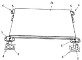
- FIG. 2 is a perspective view showing a structure of a laying free access floor shown as a single floor panel.
- FIG. 3 is a perspective view of the support leg.
- FIG. 4 is a perspective view showing the original shape of the main plate.
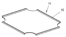
- FIG. 5 is a perspective view showing the structure of a reinforced steel plate.
- FIG. 6 is a perspective view of the corners of the floor panel as seen from the lower surface side.
- FIG. 7 is a front view showing a state in which the two front floor panels 2c and 2d are removed from the four-corner gathering portion.
- FIG. 8 is a front view showing the adjacent state of the floor panel.
- FIG. 1 is a plan view showing a part of a completed free access floor 1, and shows portions of four floor panels 2a, 2b, 2c, and 2d. Here, when not distinguishing each floor panel, it is called a floor panel 2.
- the four corner collecting portions 3 are supported by the support legs 4 on the lower surface side.
- the floor panel 2 is assembled by bridging the corners of the floor panel 2 on the pedestal 5 between the pedestals 5 of the plurality of support legs 4 arranged on the slab surface of the building. Laying by placing.
- the support leg 4 is attached to a base plate 6 such that a support column 7 is erected, and a pedestal 5 is passed through the support column 7 so that the vertical position can be adjusted.
- the support column 7 is a threaded rod, and a female screw portion 8 at the center of the base 5 is screwed to the support column 7.
- Reference numeral 9 is a set screw.
- the pedestal 5 is rotated to determine the vertical position, and the retaining screw 9 is screwed to fix the position.
- the pedestal 5 is provided with four positioning projections 5a on the upper surface and two projections so as to face each other along a cross line with the intersection point aligned with the center of the pedestal.
- a cushion material 5b made of synthetic rubber is bonded to the center portion of the upper surface of the base 5 and surrounded by the protrusion 5a.
- the floor panel 2 includes a main plate 10 and a reinforcing steel plate 11.
- the main plate 10 is a compression-molded solid calcium silicate plate, which is basically a square of 500 mm ⁇ 500 mm in plan view as shown in FIG. 4 and has a thickness of 23.5 to 31 mm. It is a thick board. The thickness varies depending on the allowable concentrated load. In FIG. 4, the thickness is emphasized. And it is the form which made the side surface of the thickness direction of 4 rounds into the taper surface 13 which inclined to the vertical surface 12 and the in-plane direction below it.
- the main plate 10 is formed from a siliceous raw material, a calcareous raw material, and fly ash mixed with water and then subjected to steam curing at high temperature and high pressure, followed by drying to obtain a raw plate (FIG. 4).
- the front and back surfaces of the original plate are ground and trimmed, and the side surfaces are ground and trimmed to the vertical surface 12 and the tapered surface 13.
- the quarter concave portion 14 is formed at the four corners of the lower surface by turning it into a circle having a diameter of about 10 mm centered on a square corner or apex at a depth of about 10 mm from the lower surface.
- the turning recess 14 is 10 mm deep from the lower surface side, the recess does not reach the upper surface and the corner is not cut out. Further, since the twisting action extends to the tapered surface 13, the corresponding portion of the twisting recess 14 has a concave cone shape (FIG. 6).
- the reinforcing steel plate 11 (FIG. 5) has a thickness of about 0.3 mm and is plated with nickel in this embodiment.
- the reinforcing steel plate 11 When the reinforcing steel plate 11 is unfolded, it has a slightly larger area than the lower surface of the main plate 10, and a portion protruding from the lower surface of the main plate around the four sides is folded upward to form a rib 15. Further, the four corners of the reinforcing steel plate 11 are cut out together with the ribs 15 at locations corresponding to 1 ⁇ 4 of a circle having a diameter slightly larger than the diameter of the wound recess 14. The rib 15 is folded along the tapered surface of the main plate, and the edge is directed toward the tapered surface 13.
- the reinforcing steel plate 11 is bonded and attached to the lower surface of the main plate 10, and the floor panel 2 is completed by performing dustproof coating on the surface of the main plate 10.
- the free access floor 1 is constructed by the following procedure. First, a plurality of support legs 4 are arranged at the support leg positions set on the slab surface of the building, for example, at the intersections of the matrix at intervals of 500 mm in length and width, and the vertical positions of the respective pedestals 5 are adjusted.
- the floor panel 2 is placed between the pedestals 5 of the plurality of support legs 1, the reinforcing steel plate 11 side is the lower surface, the vertical surfaces 12 in the four circumferences of the main plate 10 are brought into contact, and the floor panel 2 is placed at each pedestal 5. In an arrangement where the corners gather, they are bridged and placed (FIG. 1).
- each pedestal 5 is a four-corner gathering portion 3 where the corners of the four flow panels 2a to 2d gather (FIG. 1), and the corners of the floor panels 2a to 2d are floor panels as shown in FIG. 2 is mainly supported by the support leg 4 in contact with the cushion material 5b at the location of the reinforcing steel plate 11, and the concave recesses 14 on the lower side of each corner are gathered to form one cylindrical space 16,
- the top of the support 7 in the support leg 4, that is, the screw rod faces the space. That is, when the height of the pedestal 5 of the support leg 4 is lowered, the cylindrical space 16 absorbs this and adjusts the height even if the top of the column 7 protrudes from the upper surface of the pedestal 5. Can do. Further, since the cylindrical space 16 does not penetrate the upper surface of the floor panel 2, a closing member is not required for the four-corner gathering portion 3.
- the reinforced steel plate adhered to the lower surface of the main plate 10 is a reinforcement of the main plate 10, but the bulging portion of the four circumferences is folded upward as ribs 15 and the edges are directed toward the tapered surface of the main plate 10. Injuries caused by eleven sharp edges can be prevented.
- the corner of the floor panel 2 placed on the pedestal 5 is regulated by the positioning protrusion 5a on the upper surface of the pedestal 5 and is guided to an accurate position on the pedestal 5, so that it is easy to install. At this time, the contact between the positioning projection 5a and the floor panel 2 is made at the rib 15 portion of the reinforcing steel plate 11 on the taper surface of the floor panel 2, so that the floor panel 2 is not damaged at the time of crosslinking.
- the positioning projection 5a is placed in the downwardly expanding triangular space formed by the tapered surface 13 of the floor panel 2 when the floor panel 2 is placed on the pedestal 5 and abutted against each other, and the floor panel 2 is abutted and placed. Sometimes does not become an obstacle.
- the vertical surface 12 is about half the thickness dimension and the lower half is a tapered surface 13, so that although the floor panels 2 on both sides are in contact with the vertical surface 12, It is easy to remove the floor panel 2 and fit the last floor panel. Moreover, since the part which touches by the vertical surface 12 does not reach the whole thickness dimension, when a person walks on the floor panel 2, generation
Landscapes
- Engineering & Computer Science (AREA)
- Architecture (AREA)
- General Engineering & Computer Science (AREA)
- Civil Engineering (AREA)
- Structural Engineering (AREA)
- Floor Finish (AREA)
Abstract
フロアパネルと支持脚で構成する。支持脚は、ベースプレートに支柱を立設し、台座を支柱に貫通させて上下位置調節可能に取り付ける。フロアパネルを主板と補強鋼板とで構成する。主板は、圧縮成形珪酸カルシウム板であり、四周の側面が垂直面とその下方の面内方向へ傾斜したテーパー面を備えると共に、下面側の四隅に下面側から前記支柱の頂部を受け入れる抉り凹部を有する。補強鋼板の四周は主板の前記テーパー面に沿ってリブ状に上方へ折り上げられると共に、四隅を切欠いて前記抉り凹部を露出させてある。
Description
本発明は、建物のスラブ上、つまり床面上に複数の支持脚を配置し、その台座間にフロアパネルを、台座箇所でパネルの隅部が集合する配置で架橋し、載置してあるフリーアクセスフロアに関する。
オフィスビル等の建物では、室内に複写機、パソコン等の多数の電子機器を配置しており、これらの電子機器の配線を収納するため建物のスラブ上にフロアを敷設するフリーアクセスフロアが普及してきている。フリーアクセスフロアでは、フロアを支持する支持脚を建物のスラブ上に設置して、スラブ面とフロアとの間に配線を収納する空間を確保することで、フロアの上面に電子機器の配線が露出することがなくなり、快適なオフィス環境を実現することができる。
建物のスラブ面は、特に床面積が大きい場合などに、水平度に誤差が生じやすくなる。
そのため、フリーアクセスフロアでは、フロアを支持する支持脚にフロアの上下位置を調整する機能を持たせ、フロア面が水平状態に設定されるように支持脚を調整してフロアパネルを架橋し載置するなどして敷設している。こうしたフリーアクセスフロアでは、フロアパネルが頑丈であること、耐久性があること、敷設し易いことが重要である。
そのため、フリーアクセスフロアでは、フロアを支持する支持脚にフロアの上下位置を調整する機能を持たせ、フロア面が水平状態に設定されるように支持脚を調整してフロアパネルを架橋し載置するなどして敷設している。こうしたフリーアクセスフロアでは、フロアパネルが頑丈であること、耐久性があること、敷設し易いことが重要である。
フロアパネルには種々なタイプがある。例えば;
特許文献1には、上板10aと下板10bにより構成され、内部に空間が形成された中空型のフロアパネル30が記載されている。なお、このものでは、四隅部に補強構造30aを設けたことを特徴としている。
特許文献2には、中空樹脂製と推測されるフロアパネルが記載され、四隅のコーナー部分を、脚支柱1の先端部を収容するために、四隅が集合したとき円形の貫通孔となるようなコーナー穴に切欠いている。なお、このものは、コーナー穴にヒールが落ち込むのを防止するために穴埋め部材5を設けることを特徴としている。
特許文献3には、裏面に裏打ち鉄板7を備え四隅に円弧内周面5f、固定押圧面5e、テーパー内周面5gなどからなる円弧状の切欠きを備えたコンクリートパネルが記載されている。裏打ち鉄板は、四辺がパネル5の側面から内側に少し引っ込む大きさである。
特許文献1には、上板10aと下板10bにより構成され、内部に空間が形成された中空型のフロアパネル30が記載されている。なお、このものでは、四隅部に補強構造30aを設けたことを特徴としている。
特許文献2には、中空樹脂製と推測されるフロアパネルが記載され、四隅のコーナー部分を、脚支柱1の先端部を収容するために、四隅が集合したとき円形の貫通孔となるようなコーナー穴に切欠いている。なお、このものは、コーナー穴にヒールが落ち込むのを防止するために穴埋め部材5を設けることを特徴としている。
特許文献3には、裏面に裏打ち鉄板7を備え四隅に円弧内周面5f、固定押圧面5e、テーパー内周面5gなどからなる円弧状の切欠きを備えたコンクリートパネルが記載されている。裏打ち鉄板は、四辺がパネル5の側面から内側に少し引っ込む大きさである。
特許文献1のように、金属製で中空のフロアパネルは比較的軽量で成形性に富むが、集中荷重で凹むことがあり、また、発錆したり、靴音や事務機器の振動音が響いたりする難点がある。特許文献2のような樹脂性は成形性に富むが寸法精度を定めにくい。また、荷重によるたわみや変形あるいは長期的には素材の経年変化による強度の劣化などが考えられる。特許文献3のフロアパネルは、パネルの主体をなすのがコンクリートであり、耐久性、振動吸収、変形しにくい点で優れるが、成形性が悪く、割れ易く、また、敷設時にパネル下面側の辺縁が他のものとの接触によって欠け易い難点がある。また、円弧内周面5fは四隅が集合する箇所では上方へ貫通した穴となり、穴埋めをする必要がある。
本発明は、耐久性、振動吸収、変形しにくい点にすぐれる一方、敷設しやすいフロアパネルを備えたフリーアクセスフロアの提供を課題とする。
本発明は、耐久性、振動吸収、変形しにくい点にすぐれる一方、敷設しやすいフロアパネルを備えたフリーアクセスフロアの提供を課題とする。
フリーアクセスフロアをフロアパネルと支持脚で構成する。
支持脚は、ベースプレートに支柱を立設し、台座を支柱に貫通させて上下位置調節可能に取り付けた構成であり、複数を準備する。
フロアパネルは主板とその下面を覆う補強鋼板で構成する。
主板は、圧縮成形による珪酸カルシウム板をさらに成形したものであり、基本的に均等な厚さの平面視で正方形の板であり、四周の側面(厚み方向)を垂直面とその下方の面内方向へ傾斜したテーパー面を備えた形態に成形する。
支持脚は、ベースプレートに支柱を立設し、台座を支柱に貫通させて上下位置調節可能に取り付けた構成であり、複数を準備する。
フロアパネルは主板とその下面を覆う補強鋼板で構成する。
主板は、圧縮成形による珪酸カルシウム板をさらに成形したものであり、基本的に均等な厚さの平面視で正方形の板であり、四周の側面(厚み方向)を垂直面とその下方の面内方向へ傾斜したテーパー面を備えた形態に成形する。
また、下面側の四隅に下面側から前記支持脚における支柱の頂部を受け入れる抉り凹部を形成しておく。抉り凹部は上面側へ突き抜けない凹部である。
補強鋼板は、展開すると主板の下面よりも少し大きな面積を有する。そして、主板の下面に添接させたとき、下面において四周囲に張出す部分は、主板の前記テーパー面に沿ってリブ状に上方へ折り上げて留める。
補強鋼板の四隅は切欠いて前記抉り凹部を露出させる。
床面に設置された複数の支持脚の台座間にフロアパネルを、補強鋼板側を下面とし、主板四周の前記垂直面を他のフロアパネルの垂直面と当接させ、且つ、台座箇所でパネルの隅部が集合する配置で、架橋して載置する。
なお、この際に、当然に、支持脚の台座の高さを調整して、フロア全体の水平出しを行う。
補強鋼板は、展開すると主板の下面よりも少し大きな面積を有する。そして、主板の下面に添接させたとき、下面において四周囲に張出す部分は、主板の前記テーパー面に沿ってリブ状に上方へ折り上げて留める。
補強鋼板の四隅は切欠いて前記抉り凹部を露出させる。
床面に設置された複数の支持脚の台座間にフロアパネルを、補強鋼板側を下面とし、主板四周の前記垂直面を他のフロアパネルの垂直面と当接させ、且つ、台座箇所でパネルの隅部が集合する配置で、架橋して載置する。
なお、この際に、当然に、支持脚の台座の高さを調整して、フロア全体の水平出しを行う。
圧縮成形による珪酸カルシウム板は、素材的に劣化や変形が生じにくく耐久性が高い。
また、中実の緻密な素材構造であるために振動が伝播しにくく振動の吸収性に優れるので、長期にわたり安定したフロアを実現できる。フロアパネルごとの荷重によるたわみが殆どないので、しっかりとした歩行感覚を得られる。
敷設された後の各フロアパネルは、相互に側面の垂直面で当接し、面接触で収まっているので、パネルの横ずれ、撥ね上がりがなく、敷設状態が安定している。
また、中実の緻密な素材構造であるために振動が伝播しにくく振動の吸収性に優れるので、長期にわたり安定したフロアを実現できる。フロアパネルごとの荷重によるたわみが殆どないので、しっかりとした歩行感覚を得られる。
敷設された後の各フロアパネルは、相互に側面の垂直面で当接し、面接触で収まっているので、パネルの横ずれ、撥ね上がりがなく、敷設状態が安定している。
以下、本発明に係るいくつかの実施形態について詳しく説明する。なお、以下に説明する実施形態は、本発明を実施するにあたって好ましい具体例であるから、技術的に種々の限定がなされているが、本発明は、以下の説明において特に本発明を限定する旨明記されていない限り、これらの形態に限定されるものではない。
図1は、完成したフリーアクセスフロア1の一部を示した平面図であり、4枚のフロアパネル2a,2b,2c,2dの部分を示している。ここで各フロアパネルを区別しないときは、フロアパネル2と呼ぶ。四隅集合部3は下面側で支持脚4に支えられている。
フロアパネル2は、図2に一部を示すように、建物のスラブ面に配置された複数の支持脚4の台座5間に、フロアパネル2の隅部を台座5上に集合させ、架橋して載置することにより敷設する。
フロアパネル2は、図2に一部を示すように、建物のスラブ面に配置された複数の支持脚4の台座5間に、フロアパネル2の隅部を台座5上に集合させ、架橋して載置することにより敷設する。
支持脚4は、図3に示すように、ベースプレート6に支柱7を立設し、台座5を支柱7に貫通させて上下位置調節可能に取り付けてある。具体的には、支柱7はねじ棒であり、これに台座5中央の雌ねじ部8が螺合している。符合9は留めねじである。台座5を回転させて上下位置を定め、留めねじ9をねじ込んでその位置を固定する。台座5は上面に位置決め突起5aを、交差点を台座の中心に合わせた十字線に沿わせて、2個ずつ対向させて4個突設している。また、台座5の上面であって、前記突起5aで囲まれる中央部分に合成ゴム製のクッション材5bを接着してある。
フロアパネル2は、主板10と補強鋼板11とからなる。
主板10は、圧縮成形された高密度の中実の珪酸カルシウムの板であり、基本的には図4に示すように平面視で500mm×500mmのほぼ正方形であり、厚みが23.5~31mmの厚手の板である。なお、厚みは許容集中荷重によって異なる。また、図4は厚みを強調してある。そして、四周の厚み方向の側面を垂直面12とその下方の面内方向へ傾斜したテーパー面13とした形態である。
主板10は、圧縮成形された高密度の中実の珪酸カルシウムの板であり、基本的には図4に示すように平面視で500mm×500mmのほぼ正方形であり、厚みが23.5~31mmの厚手の板である。なお、厚みは許容集中荷重によって異なる。また、図4は厚みを強調してある。そして、四周の厚み方向の側面を垂直面12とその下方の面内方向へ傾斜したテーパー面13とした形態である。
主板10は、この実施例において、珪酸質原料、石灰質原料及びフライアッシュに水を加えて混合した材料を、成形し、高温・高圧で蒸気養生を行った後、乾燥させて原板を得る(図4)。ついで、原板の表裏面を研削して整え、側面を前記垂直面12とテーパー面13に研削して整える。さらに、下面の四隅に、正方形の角つまり頂点を中心とした直径約10mmの円形に、下面から上方へ約10mmの深さで抉り、1/4円形の抉り凹部14を形成する。
抉り凹部14は下面側から10mmの深さなので、この凹部が上面に達して隅部が切欠きとなることはない。また、抉り作用は、前記のテーパー面13に及ぶので、抉り凹部14の対応する部分は凹んだ円錐状となる(図6)。
抉り凹部14は下面側から10mmの深さなので、この凹部が上面に達して隅部が切欠きとなることはない。また、抉り作用は、前記のテーパー面13に及ぶので、抉り凹部14の対応する部分は凹んだ円錐状となる(図6)。
補強鋼板11(図5)は、厚さ0.3mmほどであり、この実施例においてはニッケルメッキが施されている。補強鋼板11は、展開すると主板10の下面よりも少し大きな面積を有し、主板の下面から四周囲に張出す部分を上方へ折り上げてリブ15にしリブ状としてある。また、補強鋼板11の四隅は前記抉り凹部14の径よりも少し大きな径の円の1/4に相当する箇所をリブ15と共に切除してある。前記のリブ15は、主板の前記テーパー面に沿って折り上げられ、辺縁がテーパー面13に向かっている。
主板10の下面に補強鋼板11を接着して取り付け、主板10の表面に防塵塗装を行ってフロアパネル2が完成する。
フリーアクセスフロア1は、次の手順で構築される。
まず、複数の支持脚4を建物のスラブ面に設定した支持脚位置、例えば縦横500mm間隔のマトリクスの交点、に配置し、それぞれの台座5の上下位置を整える。
フロアパネル2を前記複数の支持脚1の台座5間に、補強鋼板11側を下面とし、主板10の四周における前記垂直面12を当接させ、且つ、各台座5の箇所でフロアパネル2の隅部が集合する配置で、架橋して載置する(図1)。
フリーアクセスフロア1は、次の手順で構築される。
まず、複数の支持脚4を建物のスラブ面に設定した支持脚位置、例えば縦横500mm間隔のマトリクスの交点、に配置し、それぞれの台座5の上下位置を整える。
フロアパネル2を前記複数の支持脚1の台座5間に、補強鋼板11側を下面とし、主板10の四周における前記垂直面12を当接させ、且つ、各台座5の箇所でフロアパネル2の隅部が集合する配置で、架橋して載置する(図1)。
このとき、各台座5の箇所は4枚のフロパネル2a~2dの隅部が集合する四隅集合部3となり(図1)、フロアパネル2a~2dの隅部は、図7のように、フロアパネル2の下面が主として補強鋼板11の箇所でクッション材5bに接して支持脚4に支持され、また、各隅部下面側の抉り凹部14が寄り集まって一個の円筒状空間16を形成し、この空間に支持脚4における支柱7、つまりねじ棒、の頂部が臨んでいる。すなわち、円筒状空間16は支持脚4の台座5の高さを低くしたとき、支柱7の頂部が台座5の上面よりも突出する事態が生じてもこれを吸収して高さ調節をすることができる。また、この円筒状空間16はフロアパネル2の上面に貫通していないので、四隅集合部3に閉鎖部材を必要としない。
主板10の下面に貼着した補強鋼板は、主板10の補強であるが、四周の張り出し部をリブ15として上方に折り上げ、辺縁を主板10のテーパー面に向かわせてあるので、補強鋼板11の鋭い辺縁が原因となる怪我を防止できる。
さらに、台座5に載置されるフロアパネル2の隅部は、台座5の上面における位置決め突起5aに規制されて、台座5上の正確な位置に誘導されるので設置しやすい。このとき、位置決め突起5aとフロアパネル2との接触はフロアパネル2のテーパー面における補強鋼板11のリブ15部分で行われるので、架橋時にフロアパネル2を損傷してしまうことがない。また、前記の位置決め突起5aは、台座5にフロアパネル2を載置し、突き合わせたとき、フロアパネル2のテーパー面13が作る下広がりの三角形状空間に納まり、フロアパネル2を突き合わせ載置するときに障害とならない。
さらに、台座5に載置されるフロアパネル2の隅部は、台座5の上面における位置決め突起5aに規制されて、台座5上の正確な位置に誘導されるので設置しやすい。このとき、位置決め突起5aとフロアパネル2との接触はフロアパネル2のテーパー面における補強鋼板11のリブ15部分で行われるので、架橋時にフロアパネル2を損傷してしまうことがない。また、前記の位置決め突起5aは、台座5にフロアパネル2を載置し、突き合わせたとき、フロアパネル2のテーパー面13が作る下広がりの三角形状空間に納まり、フロアパネル2を突き合わせ載置するときに障害とならない。
さらに、敷設されたフロアパネル2同士は、主板10の垂直面12を接しているので、何らかの理由で横方向の圧力が作用しても圧力によって上下方向の成分を含む分力が生じず、撥ね上がったりしない(図8)。
一方、前記の垂直面12は、この実施例において、厚さ寸法の約半分とし、下半をテーパー面13としているので、両側のフロアパネル2を垂直面12で接しているにも関わらず、フロアパネル2の取り外しや最後のフロアパネルをはめ込む際の作業を楽に行える。
また、垂直面12で接する部分が厚さ寸法の全体に及ばないので、人がフロアパネル2上を歩いたときにこすれ音の発生が少なくなる。
一方、前記の垂直面12は、この実施例において、厚さ寸法の約半分とし、下半をテーパー面13としているので、両側のフロアパネル2を垂直面12で接しているにも関わらず、フロアパネル2の取り外しや最後のフロアパネルをはめ込む際の作業を楽に行える。
また、垂直面12で接する部分が厚さ寸法の全体に及ばないので、人がフロアパネル2上を歩いたときにこすれ音の発生が少なくなる。
1 フリーアクセスフロア
2,2a~2d フロアパネル
3 四隅集合部
4 支持脚
5 台座
5a 位置決め突起
5b クッション材
6 ベースプレート
7 支柱
8 雌ねじ部
9 留めねじ
10 主板
11 補強鋼板
12 垂直面
13 テーパー面
14 抉り凹部
15 リブ
16 円筒状空間
2,2a~2d フロアパネル
3 四隅集合部
4 支持脚
5 台座
5a 位置決め突起
5b クッション材
6 ベースプレート
7 支柱
8 雌ねじ部
9 留めねじ
10 主板
11 補強鋼板
12 垂直面
13 テーパー面
14 抉り凹部
15 リブ
16 円筒状空間
Claims (2)
- フロアパネルと支持脚で構成され、
支持脚は、ベースプレートに支柱を立設し、台座を支柱に貫通させて上下位置調節可能に取り付けてあり、
フロアパネルは主板とその下面を覆う補強鋼板で構成され、
主板は、圧縮成形珪酸カルシウム板であり、四周の側面が垂直面とその下方の面内方向へ傾斜したテーパー面を備えると共に、下面側の四隅に下面側から前記支柱の頂部を受け入れる抉り凹部が形成されており、
補強鋼板の四周は主板の前記テーパー面に沿ってリブ状に上方へ折り上げられると共に、四隅を切欠いて前記抉り凹部を露出させてあり、
床面に設置された複数の支持脚の台座間にフロアパネルを、主板四周の垂直面を他のフロアパネルの垂直面と当接させ、且つ、台座箇所でパネルの隅部が集合する配置で、架橋して載置してあることを特徴とした、
フリーアクセスフロア。 - 支持脚の台座は上面にフロアパネルの隅部を位置決めする位置決め突起を、交差点を台座の中心に合わせた十字線に沿わせて2個ずつ対向させて4個突設しており、その厚さと高さは、相互に当接したフロアパネルの下部に前記テーパー面によって形成される断面三角形の空間に納まる寸法である、
請求項1に記載のフリーアクセスフロア。
Applications Claiming Priority (2)
| Application Number | Priority Date | Filing Date | Title |
|---|---|---|---|
| JP2013181617A JP6567246B2 (ja) | 2013-09-02 | 2013-09-02 | フリーアクセスフロア |
| JP2013-181617 | 2013-09-02 |
Publications (1)
| Publication Number | Publication Date |
|---|---|
| WO2015030255A1 true WO2015030255A1 (ja) | 2015-03-05 |
Family
ID=52586798
Family Applications (1)
| Application Number | Title | Priority Date | Filing Date |
|---|---|---|---|
| PCT/JP2014/073035 Ceased WO2015030255A1 (ja) | 2013-09-02 | 2014-09-02 | フリーアクセスフロア |
Country Status (3)
| Country | Link |
|---|---|
| JP (1) | JP6567246B2 (ja) |
| TW (1) | TW201529943A (ja) |
| WO (1) | WO2015030255A1 (ja) |
Families Citing this family (8)
| Publication number | Priority date | Publication date | Assignee | Title |
|---|---|---|---|---|
| CN108811506A (zh) * | 2017-02-27 | 2018-11-13 | 株式会社海广 | 地板镶板以及具有该镶板的通路地板系统 |
| JP7060345B2 (ja) * | 2017-08-15 | 2022-04-26 | ニチアス株式会社 | フロア支持脚 |
| JP7361491B2 (ja) * | 2019-05-07 | 2023-10-16 | フクビ化学工業株式会社 | 後調整機能付きルームユニット支持脚、ルームユニット支持脚の設置高さ調整方法 |
| TWI717027B (zh) * | 2019-09-20 | 2021-01-21 | 黃建德 | 用於高架地板之地板板體 |
| CN112727004B (zh) * | 2020-12-29 | 2022-04-22 | 北京市金龙腾装饰股份有限公司 | 一种地板铺装结构 |
| CN112746541B (zh) * | 2020-12-30 | 2022-02-22 | 北京中景橙石科技股份有限公司 | 带有钢筋伞骨骨架的砼赛克结构及地面结构的施工方法 |
| TWI852678B (zh) * | 2023-07-13 | 2024-08-11 | 惠亞工程股份有限公司 | 承載結構及其高架地板 |
| TWI854742B (zh) * | 2023-07-13 | 2024-09-01 | 惠亞工程股份有限公司 | 雙層承載結構及其高架地板 |
Citations (4)
| Publication number | Priority date | Publication date | Assignee | Title |
|---|---|---|---|---|
| JPS6035708Y2 (ja) * | 1980-08-13 | 1985-10-23 | 鹿島建設株式会社 | 床装置 |
| JPH0518429Y2 (ja) * | 1986-07-15 | 1993-05-17 | ||
| JPH0868189A (ja) * | 1994-08-26 | 1996-03-12 | Ohbayashi Corp | 空調用フリーアクセスフロア |
| JP2007277884A (ja) * | 2006-04-05 | 2007-10-25 | Sekisui Chem Co Ltd | 嵌合式二重床構造 |
Family Cites Families (6)
| Publication number | Priority date | Publication date | Assignee | Title |
|---|---|---|---|---|
| JPS60112954A (ja) * | 1983-11-24 | 1985-06-19 | 株式会社東芝 | パネル |
| JPS613854U (ja) * | 1984-06-13 | 1986-01-10 | 東陶機器株式会社 | 二重床構造における床パネル |
| JPS6359943U (ja) * | 1986-10-06 | 1988-04-21 | ||
| JP2789429B2 (ja) * | 1994-08-01 | 1998-08-20 | ニチアス株式会社 | フリーアクセスフロアのレベル調整装置 |
| JP2009203616A (ja) * | 2008-02-26 | 2009-09-10 | Kyodo Ky Tec Corp | 二重床構造及び二重床設備、並びに二重床構造の床パネル |
| JP5706090B2 (ja) * | 2009-12-07 | 2015-04-22 | 共同カイテック株式会社 | 二重床用フロアパネル及び二重床設備 |
-
2013
- 2013-09-02 JP JP2013181617A patent/JP6567246B2/ja not_active Expired - Fee Related
-
2014
- 2014-09-02 WO PCT/JP2014/073035 patent/WO2015030255A1/ja not_active Ceased
- 2014-09-02 TW TW103130304A patent/TW201529943A/zh unknown
Patent Citations (4)
| Publication number | Priority date | Publication date | Assignee | Title |
|---|---|---|---|---|
| JPS6035708Y2 (ja) * | 1980-08-13 | 1985-10-23 | 鹿島建設株式会社 | 床装置 |
| JPH0518429Y2 (ja) * | 1986-07-15 | 1993-05-17 | ||
| JPH0868189A (ja) * | 1994-08-26 | 1996-03-12 | Ohbayashi Corp | 空調用フリーアクセスフロア |
| JP2007277884A (ja) * | 2006-04-05 | 2007-10-25 | Sekisui Chem Co Ltd | 嵌合式二重床構造 |
Also Published As
| Publication number | Publication date |
|---|---|
| JP2015048654A (ja) | 2015-03-16 |
| TW201529943A (zh) | 2015-08-01 |
| JP6567246B2 (ja) | 2019-08-28 |
Similar Documents
| Publication | Publication Date | Title |
|---|---|---|
| JP6567246B2 (ja) | フリーアクセスフロア | |
| JP2004511686A (ja) | タイル | |
| JP3187449U (ja) | 高床式フロアボード | |
| KR101695216B1 (ko) | 실내외 스포츠 경기장 바닥재 | |
| JP6118194B2 (ja) | 防音床構造 | |
| KR101695220B1 (ko) | 실내외 스포츠 경기장 바닥재의 제조 방법 | |
| KR101513257B1 (ko) | 저장조 기초 패드 및 이를 이용한 저장조 시공 방법 | |
| JP4177817B2 (ja) | 免震基礎構造、および木造住宅 | |
| KR101040234B1 (ko) | 데크 어셈블리 | |
| JPH11100976A (ja) | 断熱二重床の施工方法並びにそれに用いる断熱二重床ユニット及び断熱材付き床パネル | |
| JP3746051B2 (ja) | 露天用歩行床材 | |
| TWM599333U (zh) | 應用於具功能性層體樓地板系統之支撐固定件及樓地板系統 | |
| JP6931554B2 (ja) | 建築用面材 | |
| JP5635064B2 (ja) | 覆工材 | |
| KR20060072631A (ko) | 건축물 바닥 지지대 | |
| TWI696744B (zh) | 應用於具功能性層體樓地板系統之支撐固定件及樓地板系統 | |
| JP6219122B2 (ja) | 基礎構造及びその施工方法 | |
| JP4568597B2 (ja) | 免震基礎ブロックおよびこれを用いた免震基礎構造 | |
| JP2010038207A (ja) | 免震マット及び免震マットを用いた免震地盤 | |
| JP2018017077A (ja) | 二重床用支持脚及びそれを用いた二重床構造並びにその構築方法 | |
| JP3211904U (ja) | 防振部材及び二重床構造 | |
| JP5815190B2 (ja) | 石貼りパネルによる二重床 | |
| JP2009287239A (ja) | 床構造およびその構築工法 | |
| JP4822411B2 (ja) | 床構築体の構築方法 | |
| JP6395015B1 (ja) | 断熱キャップ及び床構造 |
Legal Events
| Date | Code | Title | Description |
|---|---|---|---|
| 121 | Ep: the epo has been informed by wipo that ep was designated in this application |
Ref document number: 14840803 Country of ref document: EP Kind code of ref document: A1 |
|
| NENP | Non-entry into the national phase |
Ref country code: DE |
|
| 122 | Ep: pct application non-entry in european phase |
Ref document number: 14840803 Country of ref document: EP Kind code of ref document: A1 |