WO2014178189A1 - スクロール圧縮機 - Google Patents
スクロール圧縮機 Download PDFInfo
- Publication number
- WO2014178189A1 WO2014178189A1 PCT/JP2014/002368 JP2014002368W WO2014178189A1 WO 2014178189 A1 WO2014178189 A1 WO 2014178189A1 JP 2014002368 W JP2014002368 W JP 2014002368W WO 2014178189 A1 WO2014178189 A1 WO 2014178189A1
- Authority
- WO
- WIPO (PCT)
- Prior art keywords
- scroll
- side recess
- bearing
- fixed
- fixed scroll
- Prior art date
Links
Images


Classifications
-
- F—MECHANICAL ENGINEERING; LIGHTING; HEATING; WEAPONS; BLASTING
- F04—POSITIVE - DISPLACEMENT MACHINES FOR LIQUIDS; PUMPS FOR LIQUIDS OR ELASTIC FLUIDS
- F04C—ROTARY-PISTON, OR OSCILLATING-PISTON, POSITIVE-DISPLACEMENT MACHINES FOR LIQUIDS; ROTARY-PISTON, OR OSCILLATING-PISTON, POSITIVE-DISPLACEMENT PUMPS
- F04C18/00—Rotary-piston pumps specially adapted for elastic fluids
- F04C18/02—Rotary-piston pumps specially adapted for elastic fluids of arcuate-engagement type, i.e. with circular translatory movement of co-operating members, each member having the same number of teeth or tooth-equivalents
- F04C18/0207—Rotary-piston pumps specially adapted for elastic fluids of arcuate-engagement type, i.e. with circular translatory movement of co-operating members, each member having the same number of teeth or tooth-equivalents both members having co-operating elements in spiral form
- F04C18/0246—Details concerning the involute wraps or their base, e.g. geometry
- F04C18/0269—Details concerning the involute wraps
-
- F—MECHANICAL ENGINEERING; LIGHTING; HEATING; WEAPONS; BLASTING
- F04—POSITIVE - DISPLACEMENT MACHINES FOR LIQUIDS; PUMPS FOR LIQUIDS OR ELASTIC FLUIDS
- F04C—ROTARY-PISTON, OR OSCILLATING-PISTON, POSITIVE-DISPLACEMENT MACHINES FOR LIQUIDS; ROTARY-PISTON, OR OSCILLATING-PISTON, POSITIVE-DISPLACEMENT PUMPS
- F04C18/00—Rotary-piston pumps specially adapted for elastic fluids
- F04C18/02—Rotary-piston pumps specially adapted for elastic fluids of arcuate-engagement type, i.e. with circular translatory movement of co-operating members, each member having the same number of teeth or tooth-equivalents
- F04C18/0207—Rotary-piston pumps specially adapted for elastic fluids of arcuate-engagement type, i.e. with circular translatory movement of co-operating members, each member having the same number of teeth or tooth-equivalents both members having co-operating elements in spiral form
- F04C18/0215—Rotary-piston pumps specially adapted for elastic fluids of arcuate-engagement type, i.e. with circular translatory movement of co-operating members, each member having the same number of teeth or tooth-equivalents both members having co-operating elements in spiral form where only one member is moving
-
- F—MECHANICAL ENGINEERING; LIGHTING; HEATING; WEAPONS; BLASTING
- F04—POSITIVE - DISPLACEMENT MACHINES FOR LIQUIDS; PUMPS FOR LIQUIDS OR ELASTIC FLUIDS
- F04C—ROTARY-PISTON, OR OSCILLATING-PISTON, POSITIVE-DISPLACEMENT MACHINES FOR LIQUIDS; ROTARY-PISTON, OR OSCILLATING-PISTON, POSITIVE-DISPLACEMENT PUMPS
- F04C18/00—Rotary-piston pumps specially adapted for elastic fluids
- F04C18/02—Rotary-piston pumps specially adapted for elastic fluids of arcuate-engagement type, i.e. with circular translatory movement of co-operating members, each member having the same number of teeth or tooth-equivalents
- F04C18/0207—Rotary-piston pumps specially adapted for elastic fluids of arcuate-engagement type, i.e. with circular translatory movement of co-operating members, each member having the same number of teeth or tooth-equivalents both members having co-operating elements in spiral form
- F04C18/0246—Details concerning the involute wraps or their base, e.g. geometry
- F04C18/0253—Details concerning the base
- F04C18/0261—Details of the ports, e.g. location, number, geometry
-
- F—MECHANICAL ENGINEERING; LIGHTING; HEATING; WEAPONS; BLASTING
- F04—POSITIVE - DISPLACEMENT MACHINES FOR LIQUIDS; PUMPS FOR LIQUIDS OR ELASTIC FLUIDS
- F04C—ROTARY-PISTON, OR OSCILLATING-PISTON, POSITIVE-DISPLACEMENT MACHINES FOR LIQUIDS; ROTARY-PISTON, OR OSCILLATING-PISTON, POSITIVE-DISPLACEMENT PUMPS
- F04C27/00—Sealing arrangements in rotary-piston pumps specially adapted for elastic fluids
- F04C27/001—Radial sealings for working fluid
-
- F—MECHANICAL ENGINEERING; LIGHTING; HEATING; WEAPONS; BLASTING
- F04—POSITIVE - DISPLACEMENT MACHINES FOR LIQUIDS; PUMPS FOR LIQUIDS OR ELASTIC FLUIDS
- F04C—ROTARY-PISTON, OR OSCILLATING-PISTON, POSITIVE-DISPLACEMENT MACHINES FOR LIQUIDS; ROTARY-PISTON, OR OSCILLATING-PISTON, POSITIVE-DISPLACEMENT PUMPS
- F04C27/00—Sealing arrangements in rotary-piston pumps specially adapted for elastic fluids
- F04C27/005—Axial sealings for working fluid
-
- F—MECHANICAL ENGINEERING; LIGHTING; HEATING; WEAPONS; BLASTING
- F04—POSITIVE - DISPLACEMENT MACHINES FOR LIQUIDS; PUMPS FOR LIQUIDS OR ELASTIC FLUIDS
- F04C—ROTARY-PISTON, OR OSCILLATING-PISTON, POSITIVE-DISPLACEMENT MACHINES FOR LIQUIDS; ROTARY-PISTON, OR OSCILLATING-PISTON, POSITIVE-DISPLACEMENT PUMPS
- F04C27/00—Sealing arrangements in rotary-piston pumps specially adapted for elastic fluids
- F04C27/008—Sealing arrangements in rotary-piston pumps specially adapted for elastic fluids for other than working fluid, i.e. the sealing arrangements are not between working chambers of the machine
-
- F—MECHANICAL ENGINEERING; LIGHTING; HEATING; WEAPONS; BLASTING
- F04—POSITIVE - DISPLACEMENT MACHINES FOR LIQUIDS; PUMPS FOR LIQUIDS OR ELASTIC FLUIDS
- F04C—ROTARY-PISTON, OR OSCILLATING-PISTON, POSITIVE-DISPLACEMENT MACHINES FOR LIQUIDS; ROTARY-PISTON, OR OSCILLATING-PISTON, POSITIVE-DISPLACEMENT PUMPS
- F04C28/00—Control of, monitoring of, or safety arrangements for, pumps or pumping installations specially adapted for elastic fluids
- F04C28/24—Control of, monitoring of, or safety arrangements for, pumps or pumping installations specially adapted for elastic fluids characterised by using valves controlling pressure or flow rate, e.g. discharge valves or unloading valves
- F04C28/26—Control of, monitoring of, or safety arrangements for, pumps or pumping installations specially adapted for elastic fluids characterised by using valves controlling pressure or flow rate, e.g. discharge valves or unloading valves using bypass channels
-
- F—MECHANICAL ENGINEERING; LIGHTING; HEATING; WEAPONS; BLASTING
- F04—POSITIVE - DISPLACEMENT MACHINES FOR LIQUIDS; PUMPS FOR LIQUIDS OR ELASTIC FLUIDS
- F04C—ROTARY-PISTON, OR OSCILLATING-PISTON, POSITIVE-DISPLACEMENT MACHINES FOR LIQUIDS; ROTARY-PISTON, OR OSCILLATING-PISTON, POSITIVE-DISPLACEMENT PUMPS
- F04C29/00—Component parts, details or accessories of pumps or pumping installations, not provided for in groups F04C18/00 - F04C28/00
- F04C29/0042—Driving elements, brakes, couplings, transmissions specially adapted for pumps
- F04C29/005—Means for transmitting movement from the prime mover to driven parts of the pump, e.g. clutches, couplings, transmissions
-
- F—MECHANICAL ENGINEERING; LIGHTING; HEATING; WEAPONS; BLASTING
- F04—POSITIVE - DISPLACEMENT MACHINES FOR LIQUIDS; PUMPS FOR LIQUIDS OR ELASTIC FLUIDS
- F04C—ROTARY-PISTON, OR OSCILLATING-PISTON, POSITIVE-DISPLACEMENT MACHINES FOR LIQUIDS; ROTARY-PISTON, OR OSCILLATING-PISTON, POSITIVE-DISPLACEMENT PUMPS
- F04C29/00—Component parts, details or accessories of pumps or pumping installations, not provided for in groups F04C18/00 - F04C28/00
- F04C29/0042—Driving elements, brakes, couplings, transmissions specially adapted for pumps
- F04C29/0085—Prime movers
-
- F—MECHANICAL ENGINEERING; LIGHTING; HEATING; WEAPONS; BLASTING
- F04—POSITIVE - DISPLACEMENT MACHINES FOR LIQUIDS; PUMPS FOR LIQUIDS OR ELASTIC FLUIDS
- F04C—ROTARY-PISTON, OR OSCILLATING-PISTON, POSITIVE-DISPLACEMENT MACHINES FOR LIQUIDS; ROTARY-PISTON, OR OSCILLATING-PISTON, POSITIVE-DISPLACEMENT PUMPS
- F04C29/00—Component parts, details or accessories of pumps or pumping installations, not provided for in groups F04C18/00 - F04C28/00
- F04C29/12—Arrangements for admission or discharge of the working fluid, e.g. constructional features of the inlet or outlet
- F04C29/124—Arrangements for admission or discharge of the working fluid, e.g. constructional features of the inlet or outlet with inlet and outlet valves specially adapted for rotary or oscillating piston pumps
- F04C29/126—Arrangements for admission or discharge of the working fluid, e.g. constructional features of the inlet or outlet with inlet and outlet valves specially adapted for rotary or oscillating piston pumps of the non-return type
- F04C29/128—Arrangements for admission or discharge of the working fluid, e.g. constructional features of the inlet or outlet with inlet and outlet valves specially adapted for rotary or oscillating piston pumps of the non-return type of the elastic type, e.g. reed valves
-
- F—MECHANICAL ENGINEERING; LIGHTING; HEATING; WEAPONS; BLASTING
- F01—MACHINES OR ENGINES IN GENERAL; ENGINE PLANTS IN GENERAL; STEAM ENGINES
- F01C—ROTARY-PISTON OR OSCILLATING-PISTON MACHINES OR ENGINES
- F01C17/00—Arrangements for drive of co-operating members, e.g. for rotary piston and casing
- F01C17/06—Arrangements for drive of co-operating members, e.g. for rotary piston and casing using cranks, universal joints or similar elements
- F01C17/066—Arrangements for drive of co-operating members, e.g. for rotary piston and casing using cranks, universal joints or similar elements with an intermediate piece sliding along perpendicular axes, e.g. Oldham coupling
-
- F—MECHANICAL ENGINEERING; LIGHTING; HEATING; WEAPONS; BLASTING
- F04—POSITIVE - DISPLACEMENT MACHINES FOR LIQUIDS; PUMPS FOR LIQUIDS OR ELASTIC FLUIDS
- F04C—ROTARY-PISTON, OR OSCILLATING-PISTON, POSITIVE-DISPLACEMENT MACHINES FOR LIQUIDS; ROTARY-PISTON, OR OSCILLATING-PISTON, POSITIVE-DISPLACEMENT PUMPS
- F04C18/00—Rotary-piston pumps specially adapted for elastic fluids
- F04C18/02—Rotary-piston pumps specially adapted for elastic fluids of arcuate-engagement type, i.e. with circular translatory movement of co-operating members, each member having the same number of teeth or tooth-equivalents
- F04C18/0207—Rotary-piston pumps specially adapted for elastic fluids of arcuate-engagement type, i.e. with circular translatory movement of co-operating members, each member having the same number of teeth or tooth-equivalents both members having co-operating elements in spiral form
- F04C18/0246—Details concerning the involute wraps or their base, e.g. geometry
- F04C18/0269—Details concerning the involute wraps
- F04C18/0276—Different wall heights
-
- F—MECHANICAL ENGINEERING; LIGHTING; HEATING; WEAPONS; BLASTING
- F04—POSITIVE - DISPLACEMENT MACHINES FOR LIQUIDS; PUMPS FOR LIQUIDS OR ELASTIC FLUIDS
- F04C—ROTARY-PISTON, OR OSCILLATING-PISTON, POSITIVE-DISPLACEMENT MACHINES FOR LIQUIDS; ROTARY-PISTON, OR OSCILLATING-PISTON, POSITIVE-DISPLACEMENT PUMPS
- F04C23/00—Combinations of two or more pumps, each being of rotary-piston or oscillating-piston type, specially adapted for elastic fluids; Pumping installations specially adapted for elastic fluids; Multi-stage pumps specially adapted for elastic fluids
- F04C23/008—Hermetic pumps
Definitions
- the present invention relates to a scroll compressor.
- a partition plate is provided in the compression vessel, and a compression element having a fixed scroll and a turning scroll in a low-pressure chamber partitioned by the partition plate, and an electric element that drives the turning scroll to turn are sealed.
- a type scroll compressor is known.
- the fixed scroll boss is fitted in the holding hole of the partition plate, and the refrigerant compressed by the compression element is separated by the partition plate through the discharge port of the fixed scroll.
- the thing provided with the structure discharged to the chamber of the side is proposed (for example, refer patent document 1).
- the present invention can fix the fixed scroll by moving the axial direction between the partition plate and the main bearing, and applying high pressure to the discharge space formed between the partition plate and the fixed scroll.
- a scroll compressor capable of pressing a scroll against a turning scroll is provided.
- the present invention also provides a bearing-side recess formed on the upper surface of the main bearing, a scroll-side recess formed on the lower surface of the fixed scroll, a lower end portion inserted into the bearing-side recess portion, and an upper end portion inserted into the scroll-side recess portion.
- a scroll compressor is provided that includes a columnar member, and the columnar member is slidable with at least one of a bearing-side recess and a scroll-side recess.
- the gap between the fixed scroll and the orbiting scroll can be eliminated, and a highly efficient operation can be performed.
- the scroll side recess, the bearing side recess, and the columnar member can prevent rotation of the fixed scroll and movement in the radial direction, and allow movement of the fixed scroll in the axial direction. .
- FIG. 1 is a longitudinal sectional view showing a configuration of a hermetic scroll compressor according to a first embodiment of the present invention.
- A is a side view showing the orbiting scroll of the hermetic scroll compressor according to the present embodiment
- (b) is a cross-sectional view taken along line XX of FIG.
- the bottom view which shows the fixed scroll of the hermetic scroll compressor concerning this embodiment
- Perspective view of the fixed scroll viewed from the bottom A perspective view of the fixed scroll viewed from above.
- the perspective view which shows the main bearing of the hermetic scroll compressor concerning this embodiment The top view which shows the rotation suppression member of the sealed scroll compressor concerning this embodiment Sectional drawing of the principal part which shows the partition plate and fixed scroll of the hermetic scroll compressor concerning this embodiment
- the partial cross section perspective view which shows the principal part of the hermetic scroll compressor concerning this embodiment
- the combination figure which shows the relative position of a turning scroll and a fixed scroll in each rotation angle of the hermetic scroll compressor concerning this embodiment
- a first aspect of the present invention includes a partition plate that partitions a sealed container into a high-pressure space and a low-pressure space, a fixed scroll adjacent to the partition plate, a revolving scroll that meshes with the fixed scroll to form a compression chamber, and a revolving scroll
- a rotation suppression member that prevents rotation of the rotation and a main bearing that supports the orbiting scroll, the fixed scroll, the orbiting scroll, the rotation suppression member, and the main bearing are arranged in a low-pressure space, and the fixed scroll and the orbiting scroll are
- a scroll compressor disposed between the partition plate and the main bearing, the bearing side recess formed on the upper surface of the main bearing, the scroll side recess formed on the lower surface of the fixed scroll, and the lower end portion inserted into the bearing side recess.
- Rukoto fixed scroll is intended to move axially between the partition plate and the main bearing.
- the scroll-side recess, the bearing-side recess, and the columnar member can prevent rotation of the fixed scroll and movement in the radial direction, and allow movement of the fixed scroll in the axial direction.
- the columnar member in addition to the first aspect, is inserted into either one of the bearing side concave portion and the fixed scroll side concave portion with an interference fit or an intermediate fit. According to the second aspect, there is no need to fix the columnar member with a bolt or the like, the number of parts can be reduced, and the cost can be reduced.
- the columnar member is inserted into the concave portion on the bearing side with an interference fit or an intermediate fit. According to the third aspect, since the scroll-side recess can be inserted into the columnar member inserted into the bearing-side recess from above, assembly is facilitated.
- the fourth aspect of the present invention includes, in addition to the third aspect, a columnar member inserted into the scroll-side recess with a gap fit, and a communication hole that communicates with the space inside the sealed container in the scroll-side recess. According to the fourth aspect, by providing the communication hole, the lubricating oil or the refrigerant containing the lubricating oil is supplied between the scroll-side recess and the columnar member, and wear of the scroll-side recess or the columnar member can be reduced.
- the columnar member is provided with a communication hole communicating with the space in the sealed container in the scroll side concave portion or the bearing side concave portion inserted by an interference fit or an intermediate fit.
- a communicating hole communicating with the space in the sealed container in the scroll side concave portion or the bearing side concave portion inserted by an interference fit or an intermediate fit.
- the fitting gap between the bearing-side recess and the columnar member and the fitting gap between the scroll-side depression and the columnar member are different. According to the sixth aspect, by reducing the fitting gap between the bearing-side recess and the columnar member, it is possible to prevent the columnar member from coming out of the bearing-side recess, and the reliability is improved. Further, by enlarging the gap between the scroll side recess and the columnar member, when the columnar member is deformed, the scroll side recess and the columnar member can be prevented from being twisted, and the reliability of the scroll compressor can be improved.
- a region in which the column 2 member is not inserted into either the scroll-side recess or the bearing-side recess is provided.
- a lubricant or lubricating oil is provided between the columnar member and the scroll-side recess or the bearing-side recess. Since the refrigerant containing is supplied, wear between the columnar member and the scroll-side recess or the bearing-side recess can be reduced.
- At least two columnar members are provided, and the positional relationship between the main bearing and the fixed scroll is constrained by two or more columnar members.
- the bearing-side concave portion and the columnar member can restrain the positional relationship between the main bearing and the fixed scroll, it is not necessary to provide a member for restraining the position as a separate member, thereby reducing the cost. be able to.
- a pin hole is provided in the insertion portion of the columnar member in the bearing-side recess, and a columnar member drop prevention pin is provided in the pin hole. According to the ninth aspect, the columnar member can be prevented from coming off, and the reliability of the scroll compressor can be improved.
- the movable range in the axial direction of the fixed scroll is regulated by the partition plate.
- the fixed scroll moves in the axial direction, it contacts the partition plate, so that the end surface of the first seal member or the end surface of the second seal member contacts the fixed scroll and deforms. Therefore, since the sealing performance is not lowered, the reliability of the scroll compressor can be improved.
- a ring-shaped first seal member disposed on the outer periphery of the discharge space between the partition plate and the fixed scroll, the partition plate, An intermediate pressure space formed between the first seal member and the second seal member is discharged between the fixed scroll and a ring-shaped second seal member disposed on the outer periphery of the first seal member.
- the pressure is lower than the pressure in the space and higher than the pressure in the low-pressure space, and the first seal member and the second seal member are sandwiched between the partition plates by the closing member.
- the eleventh aspect by forming an intermediate pressure space in addition to the high pressure discharge space between the partition plate and the fixed scroll, it is easy to adjust the pressing force of the fixed scroll against the orbiting scroll. Further, according to the eleventh aspect, since the discharge space and the intermediate pressure space are formed by the first seal member and the second seal member, the refrigerant leaks from the high pressure discharge space to the intermediate pressure space, and the intermediate pressure space. Leakage of refrigerant into the low pressure space can be reduced.
- the eleventh aspect after assembling the partition plate, the first seal member, the second seal member, and the closure member in order to sandwich the first seal member and the second seal member between the partition plate by the closure member, Since it can be placed in a closed container, the number of parts can be reduced and the scroll compressor can be easily assembled.
- an intermediate pressure port that communicates a compression chamber with an intermediate pressure space is formed on a fixed scroll, and an intermediate pressure check valve that can close the intermediate pressure port is provided. It is. According to the twelfth aspect, it is easy to adjust the pressure in the intermediate pressure space by using the pressure in the compression chamber for the intermediate pressure space. According to the twelfth aspect, since the intermediate pressure check valve is interposed between the compression chamber and the intermediate pressure space, the pressure in the intermediate pressure space can be kept constant, and the fixed scroll with respect to the orbiting scroll. Can be pressed stably.
- the thirteenth aspect of the present invention is the thickness of the inner wall and the outer wall in the fixed spiral wrap of the fixed scroll, and the thickness of the inner wall and the outer wall in the orbiting scroll of the orbiting scroll.
- the fixed spiral wrap and the swirl spiral wrap are formed so as to gradually become thinner from the winding start end to the end. According to the thirteenth aspect, by gradually reducing the thickness toward the end, the confined volume of the suction gas can be increased, and the spiral wrap can be reduced in weight, so that the centrifugal force caused by the contact of the spiral wrap can be reduced.
- the spiral wrap can be made thin as in the thirteenth aspect.
- FIG. 1 is a longitudinal sectional view showing a configuration of a hermetic scroll compressor according to the present embodiment.
- the hermetic scroll compressor includes a hermetic container 10 formed in a cylindrical shape extending in the vertical direction.
- a partition plate 20 for partitioning the inside of the sealed container 10 up and down is provided at the upper part in the sealed container 10.
- the partition plate 20 divides the sealed container 10 into a high-pressure space 11 and a low-pressure space 12.
- the sealed container 10 is provided with a refrigerant suction pipe 13 for introducing a refrigerant into the low pressure space 12 and a refrigerant discharge pipe 14 for discharging the compressed refrigerant from the high pressure space 11.
- the bottom of the low-pressure space 12 forms an oil reservoir 15 in which lubricating oil is stored.
- the low pressure space 12 includes a fixed scroll 30 and a turning scroll 40 as a compression mechanism.
- the fixed scroll 30 is adjacent to the partition plate 20.
- the orbiting scroll 40 is engaged with the fixed scroll 30 to form a compression chamber 50.
- a main bearing 60 that supports the orbiting scroll 40 is provided below the fixed scroll 30 and the orbiting scroll 40.
- a bearing portion 61 and a boss housing portion 62 are formed in the approximate center of the main bearing 60.
- the main bearing 60 is formed with a return pipe 63 having one end opened in the boss housing 62 and the other end opened on the lower surface of the main bearing 60.
- One end of the return pipe 63 may be opened on the upper surface of the main bearing 60. Further, the other end of the return pipe 63 may be opened on the side surface of the main bearing 60.
- the bearing portion 61 supports the rotating shaft 70.
- the rotating shaft 70 is supported by the bearing portion 61 and the auxiliary bearing 16.
- An eccentric shaft 71 that is eccentric with respect to the axis of the rotation shaft 70 is formed at the upper end of the rotation shaft 70.
- An oil passage 72 through which the lubricating oil passes is formed inside the rotary shaft 70.
- a lubricating oil suction port 73 is provided at the lower end of the rotating shaft 70.
- a paddle 74 is formed on the upper portion of the suction port 73.
- the oil passage 72 communicates with the suction port 73 and the paddle 74 and is formed in the axial direction of the rotary shaft 70.
- the oil passage 72 includes an oil supply port 75 for supplying oil to the bearing portion 61, an oil supply port 76 for supplying oil to the auxiliary bearing 16, and an oil supply port 77 for supplying oil to the boss housing portion 62.
- the electric element 80 includes a stator 81 fixed to the hermetic container 10 and a rotor 82 arranged inside the stator 81.
- the rotor 82 is fixed to the rotating shaft 70.
- Balance weights 17 a and 17 b are attached to the rotating shaft 70 above and below the rotor 82.
- the balance weight 17a and the balance weight 17b are arranged at positions shifted by 180 °. The balance between the centrifugal force generated by the balance weights 17a and 17b and the centrifugal force generated by the revolving motion of the orbiting scroll 40 is balanced.
- the balance weights 17a and 17b may be fixed to the rotor 82.
- the rotation suppression member (Oldham ring) 90 prevents the orbiting scroll 40 from rotating.
- the orbiting scroll 40 is supported by the fixed scroll 30 via the rotation suppression member 90. Thereby, the orbiting scroll 40 performs the orbiting motion without rotating with respect to the fixed scroll 30.
- the columnar member 100 prevents the fixed scroll 30 from rotating and moving in the radial direction, and allows the fixed scroll 30 to move in the axial direction.
- the fixed scroll 30 is supported by the main bearing 60 by the columnar member 100 and can move in the axial direction between the partition plate 20 and the main bearing 60.
- the fixed scroll 30, the orbiting scroll 40, the electric element 80, the rotation suppressing member 90, and the main bearing 60 are disposed in the low pressure space 12, and the fixed scroll 30 and the orbiting scroll 40 are disposed between the partition plate 20 and the main bearing 60. Be placed.
- the rotating shaft 70 and the eccentric shaft 71 rotate together with the rotor 82.
- the orbiting scroll 40 orbits without rotating by the rotation suppressing member 90, and the refrigerant is compressed in the compression chamber 50.
- the refrigerant is introduced from the refrigerant suction pipe 13 into the low pressure space 12.
- the refrigerant in the low pressure space 12 on the outer periphery of the orbiting scroll 40 is guided to the compression chamber 50.
- the refrigerant is compressed in the compression chamber 50 and then discharged from the refrigerant discharge pipe 14 via the high-pressure space 11.
- the lubricating oil stored in the oil reservoir 15 enters the oil passage 72 through the suction port 73 and is pumped upward along the paddle 74 of the oil passage 72.
- the pumped-up lubricating oil is supplied to the bearing portion 61, the auxiliary bearing 16, and the boss accommodating portion 62 from the respective oil supply ports 75, 76, 77.
- the lubricating oil pumped up to the boss accommodating portion 62 is guided to the sliding surface between the main bearing 60 and the orbiting scroll 40 and is discharged through the return pipe 63 and returned to the oil reservoir 15 again.
- FIG. 2A is a side view showing the orbiting scroll of the hermetic scroll compressor according to the present embodiment
- FIG. 2B is a sectional view taken along line XX of FIG. 2A.
- the orbiting scroll 40 includes a disc-like orbiting scroll end plate 41, a spiral orbiting swirl wrap 42 erected on the upper surface of the orbiting scroll end plate 41, and a cylindrical shape formed at the substantially lower center of the orbiting scroll end plate 41.
- the boss 43 is provided.
- the thickness of the inner wall and the outer wall of the swirl spiral wrap 42 is formed so as to gradually decrease from the winding start end 42a to the end end 42b of the swirl spiral wrap 42.
- FIG.2 (b) the edge part 44 by the side of the end surface in which the turning spiral wrap 42 of the turning scroll end plate 41 is formed is shown by a thick solid line.
- a convex portion 44 a is formed on the edge portion 44.
- the convex portion 44a is provided in the vicinity of the terminal end 42b.
- a pair of first key grooves 91 are formed in the orbiting scroll end plate 41.
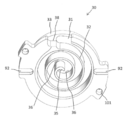
- FIG. 3 is a bottom view showing the fixed scroll of the hermetic scroll compressor according to the present embodiment
- FIG. 4 is a perspective view of the fixed scroll viewed from the bottom
- FIG. 5 is a perspective view of the fixed scroll viewed from the top.
- the fixed scroll 30 is erected so as to surround the disk-shaped fixed scroll end plate 31, a spiral fixed spiral wrap 32 standing on the lower surface of the fixed scroll end plate 31, and the periphery of the fixed spiral wrap 32.
- a peripheral wall 33 and a flange 34 provided around the peripheral wall 33 are provided.
- the thickness of the inner wall and the outer wall of the fixed spiral wrap 32 is formed so as to gradually decrease from the winding start end 32a to the end 32b of the fixed spiral wrap 32.
- the terminal end 32b is a portion where the fixed spiral wrap 32 is formed from the inner wall and the outer wall, and the fixed spiral wrap 32 is further extended only by the inner wall from the terminal end 32b to the innermost wall outermost peripheral portion 32c by about 340 °. .
- the fixed spiral wrap 32 is further extended only by the inner wall from the terminal end 32b to the innermost wall outermost peripheral portion 32c by about 340 °. .
- a first discharge port 35 is formed at a substantially central portion of the fixed scroll end plate 31.
- the fixed scroll end plate 31 is provided with a bypass port 36 and an intermediate pressure port 37.
- the bypass port 36 is located in the vicinity of the first discharge port 35 and in a high pressure region immediately before completion of compression.
- the intermediate pressure port 37 is located in an intermediate pressure region during compression.
- the fixed scroll end plate 31 protrudes above the flange 34.
- a suction portion 38 for taking in the refrigerant into the compression chamber 50 is formed on the peripheral wall 33 and the flange 34 of the fixed scroll 30.
- a second keyway 92 is formed in the flange 34. Further, the flange 34 is formed with a scroll-side recess 101 into which the upper end portion of the columnar member 100 is inserted.
- a boss portion 39 is formed in the center on the upper surface (the surface on the partition plate 20 side) of the fixed scroll 30.
- a discharge space 30H is formed by a recess, and the first discharge port 35 and the bypass port 36 are formed in the discharge space 30H.
- a ring-shaped recess is formed on the upper surface of the fixed scroll 30 between the peripheral wall 33 and the boss portion 39. This ring-shaped recess forms an intermediate pressure space 30M that is lower than the pressure in the discharge space 30H and higher than the pressure in the low pressure space 12.
- An intermediate pressure port 37 is formed in the intermediate pressure space 30M.
- the intermediate pressure port 37 is configured with a diameter smaller than the thickness of the inner wall and the outer wall of the swirl spiral wrap 42. By making the diameter of the intermediate pressure port 37 smaller than the thickness of the inner wall and the outer wall of the swirl spiral wrap 42, the compression chamber 50 formed on the inner wall side of the swirl spiral wrap 42 and the outer wall side of the swirl spiral wrap 42 are formed. The communication with the compression chamber 50 can be prevented.
- An intermediate pressure check valve 111 and an intermediate pressure check valve stop 112 that can freely close the intermediate pressure port 37 are provided in the intermediate pressure space 30M.
- the intermediate pressure check valve 111 can be reduced in height by using a reed valve. Further, the intermediate pressure check valve 111 can be constituted by a ball valve and a spring.
- bypass check valve 121 In the discharge space 30H, a bypass check valve 121 and a bypass check valve stop 122 that can close the bypass port 36 are provided.
- the bypass check valve 121 can be reduced in height by using a reed valve type check valve.
- the bypass check valve 121 uses a reed valve type check valve formed in a V-shape, so that the bypass check valve 121 communicates with the compression chamber 50 formed on the outer wall side of the swirl spiral wrap 42 by a single reed valve.
- the bypass port 36A that communicates with the compression chamber 50 that is formed on the inner wall side of the swirl spiral wrap 42 can be closed.
- the shapes of the swirl spiral wrap 42 of the orbiting scroll 40 shown in FIG. 2 and the fixed spiral wrap 32 of the fixed scroll 30 shown in FIG. 3 will be described below.
- the thickness at the end of winding of the fixed spiral wrap 32 and the orbiting spiral wrap 42 can be reduced, so that the fixed scroll 30 and the orbiting scroll 40 can be reduced in weight.
- the orbiting scroll 40 can reduce the load on the bearing portion 61 due to the centrifugal force reduction effect at the time of orbital driving due to the weight reduction.
- the balance weights 17a and 17b provided on the rotating shaft 70 can be reduced in size, the degree of freedom in design can be improved.
- the extension angle can be designed larger than the conventional spiral wrap shape, the compression ratio and the volume can be increased. Therefore, the scroll compressor can be more efficiently and miniaturized.
- the fixed spiral wrap 32 and the swirl spiral wrap 42 can be made thin.
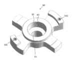
- FIG. 6 is a perspective view showing a main bearing of the hermetic scroll compressor according to the present embodiment.
- the bearing portion 61 and the boss housing portion 62 are formed at the approximate center of the main bearing 60.
- a bearing-side recess 102 into which the lower end portion of the columnar member 100 is inserted is formed on the outer peripheral portion of the main bearing 60. It is desirable that the bottom surface of the bearing-side recess 102 communicates with the return pipe 63. In this case, lubricating oil is supplied to the bearing-side recess 102 through the return pipe 63, and the fitting between the columnar member 100 and the scroll-side recess 101 and the fitting between the columnar member 100 and the bearing-side recess 102 are performed. Can improve the reliability.
- FIG. 7 is a top view showing the rotation suppressing member of the hermetic scroll compressor according to the present embodiment.
- the rotation suppressing member (Oldham ring) 90 is formed with a first key 93 and a second key 94.
- the first key 93 engages with the first key groove 91 of the orbiting scroll 40
- the second key 94 engages with the second key groove 92 of the fixed scroll 30. Therefore, the orbiting scroll 40 can perform the orbiting movement without rotating with respect to the fixed scroll 30.
- the fixed scroll 30, the orbiting scroll 40, and the Oldham ring 90 are arranged in this order from above in the axial direction of the rotary shaft 70.
- the first key 93 and the second key 94 of the Oldham ring 90 are formed on the same plane of the ring portion 95. Therefore, when the Oldham ring 90 is processed, the first key 93 and the second key 94 can be processed from the same direction, and the number of times the Oldham ring 90 is detached from the processing apparatus can be reduced. Improvement in accuracy and reduction in machining costs can be obtained.
- the Oldham ring 90 has a virtual intersection O ′ between a first imaginary line connecting the centers of the pair of first keys 93 and a second imaginary line connecting the centers of the pair of second keys 94. 2 is offset by a distance L with respect to the midpoint O of the imaginary line (the midpoint of the end portion in the radial direction of the second key 94).
- the first keyway 91 of the orbiting scroll 40 can be offset from the center of the orbiting scroll end plate 41 as shown in FIG.
- the distance to 42 can be increased.
- the extension angle of the orbiting spiral wrap 42 can be increased. For this reason, it is easy to increase the compression ratio and volume, and the scroll compressor can be made more efficient and smaller.
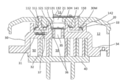
- FIG. 8 is a cross-sectional view of a main part showing a partition plate and a fixed scroll of the hermetic scroll compressor according to the present embodiment.
- a second discharge port 21 is formed at the center of the partition plate 20.
- the second discharge port 21 is provided with a discharge check valve 131 and a discharge check valve stop 132.
- a discharge space 30 ⁇ / b> H communicating with the first discharge port 35 is formed between the partition plate 20 and the fixed scroll 30.
- a check valve is not provided between the first discharge port 35 and the discharge space 30H.
- the second discharge port 21 communicates the discharge space 30 ⁇ / b> H with the high-pressure space 11.
- the discharge check valve 131 closes the second discharge port 21.
- the high pressure is applied to the discharge space 30 ⁇ / b> H formed between the partition plate 20 and the fixed scroll 30 to press the fixed scroll 30 against the orbiting scroll 40.
- Since high pressure is applied to the discharge space 30H it is important to reduce the axial projection area of the discharge space 30H as much as possible to prevent excessive pressing of the fixed scroll 30 against the orbiting scroll 40 and to improve reliability. is there.
- the axial projection area of the discharge space 30H is reduced, it becomes difficult to dispose check valves in both the first discharge port 35 and the bypass port 36.
- the discharge check valve 131 is disposed in the second discharge port 21 without arranging the check valve in the first discharge port 35.
- the bypass chamber 36 communicates the compression chamber 50 and the discharge space 30 ⁇ / b> H, and the bypass port 36 is provided with the bypass check valve 121. Since the refrigerant can be led to the discharge space 30H when reaching a predetermined pressure while preventing the refrigerant from flowing back from the space 30H, high efficiency can be realized in a wide operation range.
- the discharge check valve 131 has a larger spring constant than the bypass check valve 121.
- the thickness of the discharge check valve 131 is made thicker than the thickness of the bypass check valve 121.
- the average flow path area of the second discharge port 21 is larger than the average flow path area of the first discharge port 35. Since the refrigerant passing through the first discharge port 35 and the refrigerant passing through the bypass port 36 flow into the second discharge port 21, the average flow area of the second discharge port 21 is set to the average flow path of the first discharge port 35. By making it larger than the area, the loss of discharge pressure can be reduced. Further, a chamfer is provided at the port inlet on the discharge space 30H side in the second discharge port 21, and a loss of discharge pressure can be reduced by forming a chamfer at the end face of the port inlet.
- the hermetic scroll compressor includes a ring-shaped first seal member 141 disposed on the outer periphery of the discharge space 30H between the partition plate 20 and the fixed scroll 30, and the partition plate 20 and the fixed scroll 30. And a ring-shaped second seal member 142 disposed on the outer periphery of the first seal member 141.
- first seal member 141 and the second seal member 142 for example, polytetrafluoroethylene, which is a fluororesin, is suitable in terms of sealability and assemblability.
- the first seal member 141 and the second seal member 142 improve the reliability of the seal by mixing the fiber material with the fluororesin.
- the first seal member 141 and the second seal member 142 are sandwiched between the partition plates 20 by the closing member 150.
- the closing member 150 can be caulked with the partition plate 20 by using an aluminum material.
- An intermediate pressure space 30 ⁇ / b> M is formed between the first seal member 141 and the second seal member 142. Since the intermediate pressure space 30M communicates with the compression chamber 50 in the intermediate pressure region in the middle of compression by the intermediate pressure port 37, a pressure lower than the pressure of the discharge space 30H and higher than the pressure of the low pressure space 12 is applied.
- the intermediate pressure space 30M is formed between the partition plate 20 and the fixed scroll 30 in addition to the high-pressure discharge space 30H, so that the pressing force of the fixed scroll 30 against the orbiting scroll 40 is increased. Easy to adjust. Further, according to the present embodiment, since the first seal member 141 and the second seal member 142 form the discharge space 30H and the intermediate pressure space 30M, the refrigerant from the discharge space 30H, which is a high pressure, to the intermediate pressure space 30M. Leakage and refrigerant leakage from the intermediate pressure space 30M to the low pressure space 12 can be reduced.
- the fixed scroll 30 is provided with the intermediate pressure port 37 that communicates the compression chamber 50 with the intermediate pressure space 30M, and the intermediate pressure check valve 111 that can close the intermediate pressure port 37 is provided. Therefore, it is easy to adjust the pressure in the intermediate pressure space 30M by using the pressure in the compression chamber 50 in the intermediate pressure space 30M. Further, according to the present embodiment, since the intermediate pressure check valve 111 is interposed between the compression chamber 50 and the intermediate pressure space 30M, the pressure in the intermediate pressure space 30M can be maintained constant, It is possible to stably press the fixed scroll 30 against the scroll 40.
- FIG. 9 is a partial cross-sectional perspective view showing a main part of the hermetic scroll compressor according to the present embodiment.
- the closing member 150 described in FIG. 8 includes a ring-shaped member 151 and a plurality of protrusions 152 formed on one surface of the ring-shaped member 151.
- the first seal member 141 is sandwiched between the upper surface on the inner peripheral side of the ring-shaped member 151 and the partition plate 20 at the outer periphery.
- the second seal member 142 is sandwiched between the inner peripheral portion between the outer peripheral upper surface of the ring-shaped member 151 and the partition plate 20.
- the ring-shaped member 151 is attached to the partition plate 20 with the first seal member 141 and the second seal member 142 sandwiched therebetween.
- the closing member 150 is attached to the partition plate 20 by inserting the protrusion 152 into the hole 22 formed in the partition plate 20 and pressing the ring-shaped member 151 against the lower surface of the partition plate 20. Clamp the part and fix it.
- the inner peripheral portion of the first seal member 141 protrudes toward the inner peripheral side of the ring-shaped member 151, and the outer peripheral portion of the second seal member 142 is the same as the ring-shaped member 151. Projects to the outer periphery.
- a bearing-side recess 102 is formed on the outer peripheral upper surface of the main bearing 60, and a scroll-side recess 101 is formed on the outer peripheral lower surface of the fixed scroll 30.
- the columnar member 100 has a lower end inserted into the bearing-side recess 102 and an upper end inserted into the scroll-side recess 101. Since the columnar member 100 is slidable with at least one of the bearing-side recess 102 and the scroll-side recess 101, the fixed scroll 30 can move in the axial direction between the partition plate 20 and the main bearing 60.
- the bottom surface of the bearing-side recess 102 communicates with the outside of the main bearing 60 through the return pipe 63, and the bottom of the scroll-side recess 101 communicates with the outside of the fixed scroll 30 through the communication hole 101a.
- the scroll-side concave portion 101, the bearing-side concave portion 102, and the columnar member 100 can prevent the fixed scroll 30 from rotating and moving in the radial direction, and allow the fixed scroll 30 to move in the axial direction.
- the eccentric shaft 71 is inserted into the boss 43 via a swing bush 78 and a swivel bearing 79 so as to be capable of swiveling.
- the swing bush 78 functions as a compliance mechanism in the centrifugal direction due to the centrifugal force in the orbiting motion during operation, and the orbiting scroll 40 is displaced in the centrifugal direction, so that the orbiting scroll 40 is fixed to the fixed scroll 30.
- the gap between the swirl spiral wrap 42 and the fixed spiral wrap 32 can be minimized, and refrigerant leakage from the gap can be reduced.
- the bypass port 36 since the bypass port 36 is provided, the force in the centrifugal direction required to overcome the gas force in the compression chamber 50 is reduced by the amount by which excessive compression can be reduced. Therefore, it can be designed so that the orbiting scroll 40 is always pressed against the fixed scroll 30 in a wide driving range. If the orbiting scroll 40 is designed to be pressed against the fixed scroll 30 even under excessive compression conditions with a large compression load, the orbiting scroll 40 will be excessively pressed against the fixed scroll 30 under low compression loads. Increase in reliability and reliability.
- FIG. 10 is a combination diagram showing the relative positions of the orbiting scroll and the fixed scroll at each rotation angle of the hermetic scroll compressor according to the present embodiment.
- the compression chamber 50 ⁇ / b> A is formed by the outer wall of the swirl spiral wrap 42 of the orbiting scroll 40 and the inner wall of the fixed swirl wrap 32 of the fixed scroll 30.
- the compression chamber 50 ⁇ / b> B is formed by the inner wall of the swirl spiral wrap 42 of the orbiting scroll 40 and the outer wall of the fixed swirl wrap 32 of the fixed scroll 30.
- FIG. 10A shows a state in which the compression chamber 50A is immediately after completion of the suction closing.
- 10 (b) shows a state where 90 ° rotation has progressed from FIG. 10 (a), FIG.
- FIG. 10 (c) shows a state where 90 ° rotation has progressed from FIG. 10 (b), and FIG. 10 (d) shows FIG. ) Shows a state in which the rotation of 90 ° has progressed from FIG. 10D, and the rotation of 90 ° advances from FIG. 10D to return to the state of FIG.
- FIG. 10C shows a state in which the compression chamber 50B is immediately after the suction is closed.
- the compression chamber 50A in which the suction confinement is completed in FIG. 10 (a) is the center of the fixed scroll 30 while reducing the volume as shown in FIGS. 10 (b), 10 (c) and 10 (d).
- the first discharge port 35 communicates with the first discharge port 35 from FIG. 10 (c) to FIG. 10 (d).
- the first bypass port 36A allows the compression chamber 50A to communicate with the discharge space 30H before the compression chamber 50A, which has been closed by suction in FIG. 10A, communicates with the first discharge port 35. Therefore, when the pressure in the compression chamber 50A becomes a pressure that pushes up the bypass check valve 121, the refrigerant in the compression chamber 50A passes through the first bypass before the compression chamber 50A communicates with the first discharge port 35.
- the compression chamber 50B in which the suction confinement is completed in FIG. 10 (c) is the center of the fixed scroll 30 while reducing the volume as shown in FIGS. 10 (d), 10 (a), and 10 (b).
- the first discharge port 35 communicates with the first discharge port 35 from FIG. 10C to FIG.
- the second bypass port 36B allows the compression chamber 50B to communicate with the discharge space 30H before the compression chamber 50B, which has been suction-closed in FIG. 10C, communicates with the first discharge port 35.
- the pressure in the compression chamber 50B becomes a pressure that pushes up the bypass check valve 121
- the refrigerant in the compression chamber 50B is passed through the second bypass before the compression chamber 50B communicates with the first discharge port 35. It is led out from the port 36B to the discharge space 30H.
- the compression chambers 50A, 50B and the discharge space 30H are communicated with the first bypass port 36A and the second bypass port 36B by the first bypass port 36A and the second bypass port 36B separately from the first discharge port 35.
- the bypass check valve 121 By providing the bypass check valve 121, the refrigerant can be led to the discharge space 30H when it reaches a predetermined pressure while preventing the reverse flow of the refrigerant from the discharge space 30H. Can be realized.
- the intermediate pressure port 37 has the suction chamber 50A after the suction confinement is completed in FIG. 10A, or the intake confinement is completed in FIG. 10C. It is provided at a position communicating with the compression chamber 50B after the operation.
- the orbiting scroll 40 is furthest away from the suction portion 38 at a position rotated by 180 ° from FIG. At this position, the edge portion 44 of the orbiting scroll 40 and the inner wall outermost peripheral portion 32c of the fixed scroll 30 are closest to each other.
- the scroll compressor according to the present embodiment by providing the convex portion 44a so as to widen a part of the outer diameter of the orbiting scroll end plate 41 of the orbiting scroll 40 to the outside of the outer diameter, the orbiting scroll 40 is driven to orbit.
- the edge portion 44 of the orbiting scroll 40 always covers the inner wall outermost peripheral portion 32c of the fixed scroll 30 when viewed from the direction of the rotation axis 70, that is, the outline of the edge portion 44 of the orbiting scroll end plate 41 of the orbiting scroll 40 is fixed.
- the outermost peripheral portion 32c of the inner wall can always be extended outward. For this reason, even when the orbiting scroll 40 bends or falls during operation, the inner wall outermost peripheral portion 32c of the fixed scroll 30 and the edge portion 44 of the orbiting scroll 40 do not come into contact with each other, and a stable driving state is always maintained. And high reliability can be realized.
- the convex portion 44a is provided at a position overlapping the suction portion 38 in the axial direction, a necessary area of the convex portion 44a can be minimized, so that an effect of further weight reduction can be obtained.
- the convex portion 44a so as to expand a part of the outer diameter of the orbiting scroll end plate 41 of the orbiting scroll 40 to the outside of the outer diameter, the edge portion 44 of the orbiting scroll 40 while the orbiting scroll 40 is driven to orbit.
- the outermost peripheral portion 32c of the inner wall of the fixed scroll 30 can be always covered when viewed from the direction of the rotary shaft 70.
- the confined volume is reduced, so that the heights of the fixed spiral wrap 32 and the swirl spiral wrap 42 need to be designed to be large in order to achieve an equivalent volume. For this reason, the spiral wrap 42 and the fixed spiral wrap 32 become higher, and there is a risk that the reliability of the spiral wrap, the rollover resistance, the workability, and the like may decrease.
- the compression ratio also decreases, it becomes easy to cause insufficient compression, which may reduce the efficiency of the compressor.
- the edge portion 44 of the orbiting scroll 40 rotates the inner wall outermost peripheral portion 32 c of the fixed scroll 30 while the orbiting scroll 40 is driven to orbit.
- the maximum outer diameter of the orbiting scroll end plate 41 of the orbiting scroll 40 can be designed only within a range in which the orbiting scroll end plate 41 does not contact the columnar member 100 that supports the fixed scroll 30 with the main bearing 60.
- the columnar member 100 In order to increase the outer diameter of the orbiting scroll end plate 41, the columnar member 100 must be reduced. For this reason, the rigidity of the columnar member 100 that supports the fixed scroll 30 on the main bearing 60 may be reduced. For this reason, high reliability and high efficiency can be realized by the configuration of the scroll compressor according to this embodiment.
- the inner wall of the fixed spiral wrap 32 of the fixed scroll 30 is formed close to the end 32 b of the orbiting scroll 40 of the orbiting scroll 40, so that the inner wall of the fixed spiral wrap 32 and the outer wall of the orbiting spiral wrap 42 are formed.
- the confining volume of the compression chamber 50B formed by the outer wall of the fixed spiral wrap 32 and the inner wall of the swirl spiral wrap 42 are made different. According to this embodiment, since the compression ratio can be increased by ensuring the maximum confined volume of the suction gas, the height of the fixed spiral wrap 32 and the swirl spiral wrap 42 can be reduced.
- the fixed scroll 30 can move in the axial direction between the partition plate 20 and the main bearing 60, and the fixed scroll 30 is pressed against the orbiting scroll 40 by the pressure of the discharge space 30H.
- the fixed scroll 30 can be stabilized when the fixed spiral wrap 32 and the swirl spiral wrap 42 are lower in height.
- the suction closed position in the compression chamber 50A and the suction closed position in the compression chamber 50B in the vicinity of the suction portion 38 the suction refrigerant passage can be shortened and the heat receiving loss can be reduced. .
- the fixed spiral wrap 32 and the swirl spiral wrap 42 It is preferable to provide a slope so that the height is higher on the suction part 38 side and gradually lowers as the distance from the suction part 38 increases. In this way, by providing the fixed spiral wrap 32 and the swirl spiral wrap 42 with slopes, it is possible to optimize the gap according to the temperature difference during operation.
- the slope amount of the fixed spiral wrap 32 is made larger than the slope amount of the swirl spiral wrap 42.
- the slope amount of the fixed swirl wrap 32 is made larger than the slope amount of the swirl swirl wrap 42. Optimization can be achieved.
- it is effective in terms of lap height management to form at least one flat portion on the outermost peripheral portion of the wrap.
- the thickness of the fixed spiral wrap 32 and the swirl spiral wrap 42 is reduced by decreasing the thickness of the fixed spiral wrap 32 and the swirl spiral wrap 42 toward the end of winding of the fixed spiral wrap 32 and the swirl spiral wrap 42.
- the rigidity is lowered, by forming the convex portion 44a on the orbiting scroll 40 as in the present embodiment, it is possible to prevent the edge portion 44 of the orbiting scroll 40 and the inner wall outermost peripheral portion 32c of the fixed scroll 30 from coming into contact with each other. Therefore, the reliability of the fixed spiral wrap 32 and the swirl spiral wrap 42 is not lowered due to abnormal vibration caused by one piece, and as a result, both high performance and high reliability can be achieved.
- the columnar member 100 is preferably inserted into either one of the bearing-side recess 102 and the scroll-side recess 101 with a fit or an intermediate fit.
- the columnar member 100 By inserting the columnar member 100 into either one of the bearing-side concave portion 102 and the scroll-side concave portion 101 with an interference fit or an intermediate fit, it is not necessary to fix the columnar member 100 with a bolt or the like, reducing the number of parts and cost. Can be reduced.
- the scroll-side recess 101 can be inserted into the columnar member 100 inserted into the bearing-side recess 102 from above, making assembly easy. become.
- the scroll compressor of this embodiment it is preferable to provide at least two or more columnar members 100. It is necessary to provide a position restraining member as a separate member by preventing rotation and radial movement of the fixed scroll 30 by two or more columnar members and restraining the positional relationship between the main bearing 60 and the fixed scroll 30. The cost can be reduced.
- the communication hole 101a is provided in the scroll-side recess 101, thereby including lubricating oil or lubricating oil.
- the refrigerant is supplied between the scroll-side recess 101 and the columnar member 100, and the wear of the scroll-side recess 101 or the columnar member 100 can be reduced.
- the scroll compressor when the columnar member 100 is inserted into the scroll-side recess 101 with an interference fit or an intermediate fit, and is inserted into the bearing-side recess 102 with a clearance fit, By providing the communication hole 102a communicating with the inside of the hermetic container 10, the air in the bearing-side concave portion 102 can be surely extracted when evacuating, and the reliability can be improved.
- the communication hole 102 a is communicated with the inside of the sealed container 10 through the return pipe 63.
- the columnar member 100 is provided with a region 100x that is not inserted into either the scroll side recess 101 or the bearing side recess 102.
- the movable range in the axial direction of the fixed scroll 30 is regulated by the partition plate 20.
- the fixed scroll 30 moves in the axial direction, it contacts the partition plate 20, so that the end surface of the first seal member 141 and the end surface of the second seal member 142 contact the fixed scroll 30 and are deformed. Therefore, since the sealing performance is not lowered, the reliability of the scroll compressor can be improved.
- FIG. 11 is a partial cross-sectional perspective view showing the main part of the hermetic scroll compressor according to the second embodiment of the present invention.
- the difference between the second embodiment of the present invention and the first embodiment of the present invention is only the part described below, and other configurations are the same as those of the first embodiment of the present invention. .
- this invention is not limited by the following embodiment.
- a pin hole is provided in the insertion portion of the columnar member 100 in the bearing-side recess 102, and a drop prevention pin 100 a for the columnar member 100 is provided in the pin hole. Thereby, it can prevent that the columnar member 100 falls out and can improve reliability. Since the removal prevention pin 100a contacts the inner wall of the sealed container 10, the removal prevention pin 100a itself does not come off.
- the present invention is useful for a compressor of a refrigeration cycle apparatus that can be used for electrical products such as a water heater, a hot water heater, and an air conditioner.
Abstract
Description
従って、旋回スクロールと固定スクロールとで形成される圧縮室の密閉性を高めるために、チップシールを用いる場合が多い。
また、本発明は、主軸受の上面に形成した軸受側凹部と、固定スクロールの下面に形成したスクロール側凹部と、下端部が軸受側凹部に挿入され、上端部がスクロール側凹部に挿入される柱状部材とを備え、柱状部材を、軸受側凹部及びスクロール側凹部の少なくとも一方と摺動自在とするスクロール圧縮機を提供する。
また、本発明のスクロール圧縮機では、スクロール側凹部、軸受側凹部、及び柱状部材によって、固定スクロールの回転と半径方向の動きを阻止でき、固定スクロールの軸方向への動きを許容することができる。
密閉容器10内の上部には、密閉容器10内を上下に仕切る仕切板20が設けられている。仕切板20は、密閉容器10内を高圧空間11と低圧空間12に区画している。
密閉容器10には、低圧空間12に冷媒を導入する冷媒吸込管13と、圧縮された冷媒を高圧空間11から吐出する冷媒吐出管14とを設けている。低圧空間12の底部は、潤滑油が貯留される油溜まり15を形成している。
低圧空間12には、圧縮機構として、固定スクロール30と旋回スクロール40とを備えている。固定スクロール30は仕切板20に隣接する。旋回スクロール40は固定スクロール30と噛み合わされて圧縮室50を形成する。
軸受部61は、回転軸70を軸支する。
回転軸70は、軸受部61と副軸受16とで支持されている。回転軸70の上端には、回転軸70の軸心に対して偏心した偏心軸71を形成している。
回転軸70の内部には、潤滑油が通過する油路72を形成している。回転軸70の下端には、潤滑油の吸込口73を備えている。吸込口73の上部には、パドル74が形成されている。油路72は、吸込口73、パドル74と連通し、回転軸70の軸方向に形成される。油路72は、軸受部61に給油する給油口75、副軸受16に給油する給油口76、ボス収容部62に給油する給油口77を備えている。
ロータ82は、回転軸70に固定される。回転軸70には、ロータ82の上方と下方にバランスウェイト17a、17bを取り付けている。バランスウェイト17aとバランスウェイト17bとは、180°ずれた位置に配置している。バランスウェイト17a、17bによる遠心力と、旋回スクロール40の公転運動により発生する遠心力とでバランスを取っている。なお、バランスウェイト17a、17bは、ロータ82に固定してもよい。
柱状部材100は、固定スクロール30の回転と半径方向の動きを阻止し、固定スクロール30の軸方向への動きを許容する。固定スクロール30は、柱状部材100によって主軸受60で支持され、仕切板20と主軸受60との間で軸方向に動くことができる。
固定スクロール30、旋回スクロール40、電動要素80、自転抑制部材90、及び主軸受60は、低圧空間12に配置され、固定スクロール30及び旋回スクロール40は、仕切板20と主軸受60との間に配置される。
冷媒は、冷媒吸込管13から低圧空間12に導入される。圧縮室50には、旋回スクロール40外周の低圧空間12にある冷媒が導かれる。冷媒は、圧縮室50で圧縮された後に、高圧空間11を経由して、冷媒吐出管14から吐出される。
回転軸70の回転によって、油溜まり15に貯留されている潤滑油は、吸込口73から油路72に入り、この油路72のパドル74に沿って上方に汲み上げられる。汲み上げられた潤滑油は、各給油口75、76、77から軸受部61、副軸受16、及びボス収容部62に供給される。ボス収容部62まで汲み上げられた潤滑油は、主軸受60と旋回スクロール40との摺動面に導かれるとともに、返送管63を通じて排出されて再び油溜まり15に戻される。
旋回スクロール40は、円板状の旋回スクロール鏡板41と、この旋回スクロール鏡板41の上面に立設された渦巻状の旋回渦巻きラップ42と、旋回スクロール鏡板41の下面略中央に形成された円筒状のボス43とを備えている。
旋回渦巻きラップ42における内壁と外壁との厚みは、旋回渦巻きラップ42の巻き始め端42aから終端42bにかけて徐々に薄くなるように形成している。このように、旋回渦巻きラップ42を終端42bにかけて徐々に薄くすることで、吸入ガスの閉じ込み容積を大きくでき、また旋回渦巻きラップ42が軽量化できるために、旋回渦巻きラップ42の触れ回りによる遠心力を小さくできる。
図2(b)では、旋回スクロール鏡板41の旋回渦巻きラップ42が形成されている端面側のエッジ部44を太実線にて示す。エッジ部44には凸部44aを形成している。凸部44aは、終端42b近傍に設けている。旋回スクロール鏡板41には、一対の第1のキー溝91を形成している。
固定スクロール30は、円板状の固定スクロール鏡板31と、この固定スクロール鏡板31の下面に立設された渦巻状の固定渦巻きラップ32と、この固定渦巻きラップ32の周囲を取り囲むように立設した周壁33と、この周壁33の周囲に設けられたフランジ34とを備えている。
固定渦巻きラップ32における内壁と外壁との厚みは、固定渦巻きラップ32の巻き始め端32aから終端32bにかけて徐々に薄くなるように形成している。ここでの終端32bは、内壁と外壁とから固定渦巻きラップ32が形成される部分であり、固定渦巻きラップ32は、終端32bから内壁最外周部32cまで更に340°程度内壁だけで延長されている。このように、固定渦巻きラップ32を終端32bにかけて徐々に薄くすることで、吸入ガスの閉じ込み容積を大きくでき、また固定渦巻きラップ32が軽量化できるために、固定渦巻きラップ32の触れ回りによる遠心力を小さくできる。
固定スクロール鏡板31は、フランジ34よりも上方に突出している。
固定スクロール30の周壁33及びフランジ34には、冷媒を圧縮室50に取り込むための吸入部38が形成されている。フランジ34には、第2のキー溝92を形成している。
また、フランジ34には、柱状部材100の上端部が挿入されるスクロール側凹部101を形成している。
また、固定スクロール30の上面には、周壁33とボス部39との間に、リング状の凹部が形成される。このリング状の凹部によって、吐出空間30Hの圧力より低く、低圧空間12の圧力よりも高い中圧空間30Mが形成される。中圧空間30Mには、中圧ポート37を形成している。中圧ポート37は、旋回渦巻きラップ42における内壁と外壁との厚みより小さい径で構成する。中圧ポート37の径を、旋回渦巻きラップ42における内壁と外壁との厚みより小さくすることで、旋回渦巻きラップ42の内壁側に形成される圧縮室50と、旋回渦巻きラップ42の外壁側に形成される圧縮室50との連通を防止できる。
中圧空間30Mには、中圧ポート37を閉塞自在な中圧逆止弁111、及び中圧逆止弁ストップ112を設ける。中圧逆止弁111には、リードバルブを用いることで高さを低くできる。また、中圧逆止弁111は、ボールバルブとバネとで構成することもできる。
吐出空間30Hには、バイパスポート36を閉塞自在なバイパス逆止弁121、及びバイパス逆止弁ストップ122を設ける。バイパス逆止弁121には、リードバルブ型逆止弁を用いることで高さを低くできる。また、バイパス逆止弁121は、V字型に成形されたリードバルブ型逆止弁を用いることで、1枚のリードバルブで、旋回渦巻きラップ42の外壁側に形成される圧縮室50と連通するバイパスポート36Aと、旋回渦巻きラップ42の内壁側に形成される圧縮室50と連通するバイパスポート36Bとを閉塞することができる。
その固定渦巻きラップ32及び旋回渦巻きラップ42の内外壁曲線は、基礎円半径をa、伸開角をθ、旋回半径をε、B及びnを係数とした場合、例えば以下の様な式にて表わされ、
xo=a・cosθ+(a・θ-B・θn)・sinθ(外壁 X座標)
yo=a・sinθ-(a・θ-B・θn)・cosθ(外壁 Y座標)
xi=a・cosθ+(a・(θ-π)-B・(θ-π)n+ε)・sinθ(内壁 X座標)
yi=a・sinθ-(a・(θ-π)-B・(θ-π)n+ε)・cosθ(内壁 Y座標)
かつ、係数BがB>0を充たす。
さらに、本実施形態のスクロール圧縮機では、吐出空間30Hの圧力によって固定スクロール30と旋回スクロール40との密閉性を確保するため、固定渦巻きラップ32及び旋回渦巻きラップ42先端にチップシールを設ける必要が無い。従って、チップシールを設けることによる固定渦巻きラップ32及び旋回渦巻きラップ42の薄さ制限が無いために、固定渦巻きラップ32及び旋回渦巻きラップ42を薄くすることができる。
軸受部61とボス収容部62とは、主軸受60の略中央に形成している。
主軸受60の外周部には、柱状部材100の下端部が挿入される軸受側凹部102を形成している。
軸受側凹部102の底面は、返送管63と連通するのが望ましい。この場合、軸受側凹部102には、返送管63によって、潤滑油が供給されることになり、柱状部材100とスクロール側凹部101との嵌合、柱状部材100と軸受側凹部102との嵌合の信頼性を高めることができる。
自転抑制部材(オルダムリング)90には、第1のキー93と第2のキー94とが形成されている。第1のキー93は、旋回スクロール40の第1のキー溝91と係合し、第2のキー94は、固定スクロール30の第2のキー溝92と係合する。従って、旋回スクロール40は、固定スクロール30に対して自転することなく旋回運動が可能となる。また、図1に示すように、回転軸70の軸方向に、上方から固定スクロール30、旋回スクロール40、オルダムリング90の順に配置している。固定スクロール30、旋回スクロール40、オルダムリング90の順に配置するため、オルダムリング90の第1のキー93と第2のキー94とはリング部95の同一平面に形成している。このため、オルダムリング90の加工時に、第1のキー93と第2のキー94を同一方向から加工することが可能となり、加工装置からオルダムリング90を脱着する回数を減らすことができるので、加工精度の向上及び加工費の削減効果を得ることができる。
仕切板20の中心部には、第2吐出ポート21を形成している。第2吐出ポート21には、吐出逆止弁131、及び吐出逆止弁ストップ132を設けている。
仕切板20と固定スクロール30との間には、第1吐出ポート35と連通する吐出空間30Hが形成される。第1吐出ポート35と吐出空間30Hとの間には逆止弁を設けない。第2吐出ポート21は、吐出空間30Hを高圧空間11に連通する。吐出逆止弁131は、第2吐出ポート21を閉塞する。
また、本実施形態によれば、第1吐出ポート35とは別に、バイパスポート36によって圧縮室50と吐出空間30Hとを連通し、バイパスポート36にはバイパス逆止弁121を設けることで、吐出空間30Hからの冷媒の逆流を防止しつつ、所定の圧力に到達した時点で吐出空間30Hへと導くことができるので、広い運転範囲で高効率を実現することができる。
第2吐出ポート21の平均流路面積は、第1吐出ポート35の平均流路面積よりも大きくしている。第2吐出ポート21へは、第1吐出ポート35を通った冷媒とバイパスポート36を通った冷媒とが流れ込むため、第2吐出ポート21の平均流路面積を第1吐出ポート35の平均流路面積より大きくすることで吐出圧力の損失を低減できる。
また、第2吐出ポート21における吐出空間30H側のポート入口には面取りを設けており、ポート入口の端面に面取りを形成することで、吐出圧力の損失を低減できる。
第1シール部材141及び第2シール部材142には、例えばフッ素樹脂であるポリテトラフルオロエチレンが、シール性と組み立て性の面で適している。また、第1シール部材141及び第2シール部材142は、フッ素樹脂に繊維材を混合させることでシールの信頼性が向上する。
第1シール部材141と第2シール部材142とは、閉塞部材150によって仕切板20に挟み込まれる。閉塞部材150には、アルミ材を用いることで仕切板20とのかしめを行える。
第1シール部材141と第2シール部材142との間には中圧空間30Mが形成される。中圧空間30Mは、中圧ポート37によって、圧縮途中の中間圧力領域にある圧縮室50と連通しているため、吐出空間30Hの圧力より低く、低圧空間12の圧力よりも高い圧力が加わる。
また、本実施形態によれば、第1シール部材141と第2シール部材142とで吐出空間30Hと中圧空間30Mとを形成するため、高圧である吐出空間30Hから中圧空間30Mへの冷媒の漏れ、中圧空間30Mから低圧空間12への冷媒の漏れを低減できる。
また、本実施形態によれば、第1シール部材141と第2シール部材142とを閉塞部材150によって仕切板20に挟み込むため、仕切板20、第1シール部材141、第2シール部材142、及び閉塞部材150を組み立てた後に、密閉容器10内に配置できるので、少ない部品点数にできるとともに、スクロール圧縮機の組み立てが容易である。
また、本実施形態によれば、固定スクロール30に、圧縮室50を中圧空間30Mに連通する中圧ポート37を形成し、中圧ポート37を閉塞自在な中圧逆止弁111を設けているので、中圧空間30Mには圧縮室50の圧力を利用することで、中圧空間30Mの圧力の調整を行いやすい。
また、本実施形態によれば、圧縮室50と中圧空間30Mとの間に中圧逆止弁111を介在させているので、中圧空間30Mの圧力を一定に維持することができ、旋回スクロール40に対する固定スクロール30の押し付けを安定して行える。
図8で説明した閉塞部材150は、図9に示すように、リング状部材151とリング状部材151の一方の面に形成される複数の突出部152とで構成されている。
第1シール部材141は、外周部をリング状部材151の内周側上面と仕切板20とで挟み込まれる。また、第2シール部材142は、内周部をリング状部材151の外周側上面と仕切板20とで挟み込まれる。
リング状部材151は、第1シール部材141と第2シール部材142とを挟み込んだ状態で仕切板20に取り付ける。
仕切板20への閉塞部材150の取り付けは、突出部152を仕切板20に形成した孔22に挿入して、リング状部材151を仕切板20の下面に押圧した状態で、突出部152の端部をかしめて固定する。
仕切板20に閉塞部材150を取り付けた状態では、第1シール部材141の内周部は、リング状部材151の内周側に突出し、第2シール部材142の外周部は、リング状部材151の外周側に突出している。
そして、閉塞部材150を取り付けた仕切板20を密閉容器10内に装着することで、第1シール部材141の内周部は、固定スクロール30のボス部39の外周面に押圧され、第2シール部材142の外周部は、固定スクロール30の周壁33の内周面に押圧される。
柱状部材100は、下端部が軸受側凹部102に挿入され、上端部がスクロール側凹部101に挿入される。
柱状部材100は、軸受側凹部102及びスクロール側凹部101の少なくとも一方と摺動自在とすることで、固定スクロール30は、仕切板20と主軸受60との間で軸方向に動くことができる。
軸受側凹部102の底面は、返送管63によって主軸受60の外部に通じ、スクロール側凹部101の底部は連通孔101aによって固定スクロール30の外部に通じている。
なお、偏心軸71は、スイングブッシュ78及び旋回軸受79を介して、ボス43に旋回駆動可能に挿入されている。このような構成によれば、運転時の旋回運動における遠心力によって、スウィングブッシュ78が遠心方向のコンプライアンス機構として機能し、旋回スクロール40が遠心方向に変位することで、旋回スクロール40が固定スクロール30に押し付けられることで、旋回渦巻きラップ42と固定渦巻きラップ32との間の隙間を最小化し、この隙間からの冷媒の漏れを低減できる。
また、バイパスポート36を備えているので、過剰圧縮を低減させられる分、圧縮室50内のガス力に打ち勝つために必要な遠心方向の力が低減する。従って、広い運転範囲で常に旋回スクロール40が固定スクロール30に押し付けられるように設計できる。
仮に、圧縮負荷の大きい過剰圧縮の条件でも旋回スクロール40が固定スクロール30に押し付けられるように設計すると、圧縮負荷の低い条件では過剰に旋回スクロール40が固定スクロール30に押し付けられてしまうため、機械損失の増加や信頼性の低下を招く。しかし、バイパスポート36を設けることで、過剰圧縮を抑制できるので、圧縮負荷の大きい条件での遠心方向の力と圧縮負荷の低い条件での遠心方向の力との差を縮めることができ、広い運転範囲で高効率かつ高い信頼性を得ることができる。
圧縮室50Aは、旋回スクロール40の旋回渦巻きラップ42の外壁と、固定スクロール30の固定渦巻きラップ32の内壁とで形成される。圧縮室50Bは、旋回スクロール40の旋回渦巻きラップ42の内壁と、固定スクロール30の固定渦巻きラップ32の外壁とで形成される。
図10(a)は、圧縮室50Aが吸入閉じ込み完了直後となった状態を示している。
図10(b)は図10(a)から90°回転が進んだ状態、図10(c)は図10(b)から90°回転が進んだ状態、図10(d)は図10(c)から90°回転が進んだ状態を示し、図10(d)から90°回転が進んで図10(a)の状態に戻る。
図10(c)は、圧縮室50Bが吸入閉じ込み直後となった状態を示している。
図10(c)で吸入閉じ込みが完了した圧縮室50Bは、図10(d)、図10(a)、図10(b)に示すように、容積を減少させながら、固定スクロール30の中心に向かって移動し、360°回転が進んだ図10(c)から図10(d)に至るまでに第1吐出ポート35に連通する。第2バイパスポート36Bは、図10(c)で吸入閉じ込みが完了した圧縮室50Bが第1吐出ポート35に連通する前から圧縮室50Bを吐出空間30Hに連通させている。従って、圧縮室50B内の圧力が、バイパス逆止弁121を押し上げる圧力となった場合には、圧縮室50Bが第1吐出ポート35に連通する前に、圧縮室50B内の冷媒は第2バイパスポート36Bから吐出空間30Hに導出される。
図10(a)から(d)に示すように、中圧ポート37は、図10(a)で吸入閉じ込みが完了した後の圧縮室50A、又は図10(c)で吸入閉じ込みが完了した後の圧縮室50Bと連通する位置に設けている。
また、凸部44aは、吸入部38と軸方向に重なる位置に設けることで、必要な凸部44aの領域を最小にすることができるため、さらなる軽量化の効果を得ることができる。
また、旋回スクロール40の旋回スクロール鏡板41の外径全周を大きくすることでも、旋回スクロール40が旋回駆動する間、旋回スクロール40のエッジ部44が、固定スクロール30の内壁最外周部32cを回転軸70方向から見て常時覆うことができる。しかし、旋回スクロール40の旋回スクロール鏡板41の最大外径は、固定スクロール30を主軸受60で支持する柱状部材100に旋回スクロール鏡板41が接触しない範囲でしか設計することはできず、旋回スクロール40の旋回スクロール鏡板41の外径を大きくするためには、柱状部材100を小さくする必要がある。このため、固定スクロール30を主軸受60に支持する柱状部材100の剛性が低下する恐れがある。
このような理由により、本実施形態におけるスクロール圧縮機の構成によって、高い信頼性と高い効率を実現できる。
本実施形態によれば、最大限の吸入ガスの閉じ込み容積を確保することで、圧縮比を高めることができるので、固定渦巻きラップ32及び旋回渦巻きラップ42の高さを低くできる。従って、固定スクロール30が、仕切板20と主軸受60との間で軸方向に動くことができ、吐出空間30Hの圧力によって固定スクロール30を旋回スクロール40に押し付けて、固定スクロール30と旋回スクロール40との密閉性を確保するスクロール圧縮機においては、固定渦巻きラップ32及び旋回渦巻きラップ42の高さが低い方が固定スクロール30を安定させることができる。
また、本実施形態では、圧縮室50Aにおける吸入閉じ込み位置と、圧縮室50Bにおける吸入閉じ込み位置とを、吸入部38近傍に設けることで、吸入冷媒通路を最短化でき、受熱損失を低減できる。
固定渦巻きラップ32のスロープ量は、旋回渦巻きラップ42のスロープ量よりも大きくする。固定渦巻きラップ32の温度が旋回渦巻きラップ42の温度よりも高いため、固定渦巻きラップ32のスロープ量を旋回渦巻きラップ42のスロープ量よりも大きくすることで、運転時の温度差に応じて隙間の最適化を図ることができる。
なお、固定渦巻きラップ32及び旋回渦巻きラップ42にスロープを設ける場合に、ラップの最外周部に少なくとも一つのフラット部を形成することが、ラップ高さの管理面で有効である。
固定渦巻きラップ32の最大高さを、旋回渦巻きラップ42の最大高さよりも大きくすることで、旋回スクロール40の片当たりを防止できる。
柱状部材100を軸受側凹部102にしまりばめ若しくは中間ばめで挿入した場合では、軸受側凹部102に挿入された柱状部材100に、上方からスクロール側凹部101を挿入することができ、組み立てが容易になる。
また、本実施形態のスクロール圧縮機では、少なくとも2本以上の柱状部材100を備えることが好ましい。2本以上の柱状部材によって、固定スクロール30の回転と半径方向の動きを阻止し、主軸受60と固定スクロール30との位置関係を拘束することで、別部材として位置拘束用部材を設ける必要がなく、コストを低減することができる。
また、本実施形態のスクロール圧縮機では、柱状部材100をしまりばめ又は中間ばめでスクロール側凹部101に挿入され、すきまばめで軸受側凹部102に挿入される場合には、軸受側凹部102に密閉容器10内と連通する連通孔102aを設けることで、軸受側凹部102内の空気を真空引き時に確実に抜くことができ、信頼性を向上できる。なお、本実施形態のスクロール圧縮機では、図9に示すように、連通孔102aは、返送管63を介在させて密閉容器10内と連通させている。
また、柱状部材100には、スクロール側凹部101と軸受側凹部102のいずれにも挿入されていない領域100xを設けている。柱状部材100の領域100xにより、柱状部材100がすきまばめでスクロール側凹部101に挿入される場合には、柱状部材100とスクロール側凹部101との間に、領域100xから潤滑油又は潤滑油を含んだ冷媒が供給される。また、柱状部材100がすきまばめで軸受側凹部102に挿入される場合には、柱状部材100と軸受側凹部102との間に、領域100xから潤滑油又は潤滑油を含んだ冷媒が供給される。そのため、柱状部材100とスクロール側凹部101又は軸受側凹部102との磨耗を低減できる。
本発明の第2の実施形態と本発明の第1の実施形態との相違点は以下で説明する部分のみであって、その他の構成については、本発明の第1の実施形態と同一である。なお、以下の実施形態によって本発明が限定されるものではない。
図11では、軸受側凹部102の柱状部材100の挿入部にピン孔を設け、ピン孔に柱状部材100の抜け防止ピン100aを設けている。これにより、柱状部材100が抜けることを防止でき、信頼性を向上できる。抜け防止ピン100aは密閉容器10の内壁に接触するため、抜け防止ピン100a自体が抜けることはない。
11 高圧空間
12 低圧空間
20 仕切板
21 第2吐出ポート
30 固定スクロール
30H 吐出空間
30M 中圧空間
31 固定スクロール鏡板
32 固定渦巻きラップ
33 周壁
34 フランジ
35 第1吐出ポート
36 バイパスポート
37 中圧ポート
38 吸入部
39 ボス部
40 旋回スクロール
41 旋回スクロール鏡板
42 旋回渦巻きラップ
43 ボス
44 エッジ部
44a 凸部
50 圧縮室
60 主軸受
61 軸受部
62 ボス収容部
63 返送管
70 回転軸
71 偏心軸
72 油路
73 吸込口
74 パドル
75 給油口
80 電動要素
90 自転抑制部材(オルダムリング)
100 柱状部材
100a 抜け防止ピン
101 スクロール側凹部
102 軸受側凹部
111 中圧逆止弁
121 バイパス逆止弁
131 吐出逆止弁
141 第1シール部材
142 第2シール部材
150 閉塞部材
Claims (13)
- 密閉容器内を高圧空間と低圧空間に区画する仕切板と、
前記仕切板に隣接する固定スクロールと、
前記固定スクロールと噛み合わされて圧縮室を形成する旋回スクロールと、
前記旋回スクロールの自転を防止する自転抑制部材と、
前記旋回スクロールを支持する主軸受と
を有し、
前記固定スクロール、前記旋回スクロール、前記自転抑制部材、及び前記主軸受を、前記低圧空間に配置し、
前記固定スクロール及び前記旋回スクロールを、前記仕切板と前記主軸受との間に配置したスクロール圧縮機であって、
前記主軸受の上面に形成した軸受側凹部と、
前記固定スクロールの下面に形成したスクロール側凹部と、
下端部が前記軸受側凹部に挿入され、上端部が前記スクロール側凹部に挿入される柱状部材と
を備え、
前記柱状部材を、前記軸受側凹部及び前記スクロール側凹部の少なくとも一方と摺動自在とすることで、前記固定スクロールが、前記仕切板と前記主軸受との間で軸方向に動くことを特徴とするスクロール圧縮機。 - 前記柱状部材を、前記軸受側凹部及び前記固定スクロール側凹部のどちらか一方にしまりばめ又は中間ばめで挿入することを特徴とする請求項1に記載のスクロール圧縮機。
- 前記柱状部材を、前記軸受側凹部にしばりばめ又は中間ばめで挿入することを特徴とする請求項1に記載のスクロール圧縮機。
- 前記柱状部材を、前記スクロール側凹部に隙間ばめで挿入し、前記スクロール側凹部に密閉容器内空間と連通する連通孔を備えること特徴とする請求項3に記載のスクロール圧縮機。
- 前記柱状部材が、しまりばめ又は中間ばめで挿入された前記スクロール側凹部又は前記軸受側凹部に、密閉容器内空間と連通する連通孔を備えることを特徴とする請求項2に記載のスクロール圧縮機。
- 前記軸受側凹部と前記柱状部材の嵌合隙間と前記スクロール側凹部と前記柱状部材の嵌合隙間が異なることを特徴とする請求項1から請求項5のいずれかに記載のスクロール圧縮機。
- 前記柱状部材が前記スクロール側凹部又は前記軸受側凹部のいずれにも挿入されてない領域を設けることを特徴とする請求項1から請求項6のいずれかに記載のスクロール圧縮機。
- 前記柱状部材を少なくとも2本以上設け、2本以上の前記柱状部材で前記主軸受と前記固定スクロールとの位置関係を拘束することを特徴とする請求項1から請求項7のいずれかに記載のスクロール圧縮機。
- 前記軸受側凹部の前記柱状部材の挿入部にピン孔を設け、前記ピン孔に前記柱状部材の抜け防止ピンを設けることを特徴とする請求項1から請求項8のいずれかに記載のスクロール圧縮機。
- 前記固定スクロールの前記軸方向への可動域を、前記固定スクロールと前記仕切板とで規制することを特徴とする請求項1から請求項9のいずれかに記載のスクロール圧縮機。
- 前記仕切板と前記固定スクロールとの間で、前記吐出空間の外周に配置されるリング状の第1シール部材と、
前記仕切板と前記固定スクロールとの間で、前記第1シール部材の外周に配置されるリング状の第2シール部材と
を備え、
前記第1シール部材と前記第2シール部材との間に形成される中圧空間を、前記吐出空間の圧力より低く、前記低圧空間の圧力よりも高くし、
前記第1シール部材と前記第2シール部材とを、閉塞部材によって前記仕切板に挟み込むことを特徴とする請求項1から請求項10のいずれかに記載のスクロール圧縮機。 - 前記固定スクロールに、前記圧縮室を前記中圧空間に連通する中圧ポートを形成し、前記中圧ポートを閉塞自在な中圧逆止弁を設けたことを特徴とする請求項11に記載のスクロール圧縮機。
- 前記固定スクロールの固定渦巻きラップにおける内壁と外壁との厚み、及び前記旋回スクロールの旋回渦巻きラップにおける内壁と外壁との厚みを、前記固定渦巻きラップ及び前記旋回渦巻きラップの巻き始め端から終端にかけて徐々に薄くなるように形成したことを特徴とする請求項1から請求項12のいずれかに記載のスクロール圧縮機。
Priority Applications (4)
| Application Number | Priority Date | Filing Date | Title |
|---|---|---|---|
| US14/888,057 US9765782B2 (en) | 2013-04-30 | 2014-04-28 | Scroll compressor |
| CN201480024543.5A CN105164419B (zh) | 2013-04-30 | 2014-04-28 | 涡旋式压缩机 |
| JP2015514753A JP6304663B2 (ja) | 2013-04-30 | 2014-04-28 | スクロール圧縮機 |
| EP14791398.2A EP2993351B1 (en) | 2013-04-30 | 2014-04-28 | Scroll compressor |
Applications Claiming Priority (2)
| Application Number | Priority Date | Filing Date | Title |
|---|---|---|---|
| JP2013-094881 | 2013-04-30 | ||
| JP2013094881 | 2013-04-30 |
Publications (1)
| Publication Number | Publication Date |
|---|---|
| WO2014178189A1 true WO2014178189A1 (ja) | 2014-11-06 |
Family
ID=51843331
Family Applications (4)
| Application Number | Title | Priority Date | Filing Date |
|---|---|---|---|
| PCT/JP2014/002370 WO2014178191A1 (ja) | 2013-04-30 | 2014-04-28 | スクロール圧縮機 |
| PCT/JP2014/002366 WO2014178188A1 (ja) | 2013-04-30 | 2014-04-28 | スクロール圧縮機 |
| PCT/JP2014/002368 WO2014178189A1 (ja) | 2013-04-30 | 2014-04-28 | スクロール圧縮機 |
| PCT/JP2014/002369 WO2014178190A1 (ja) | 2013-04-30 | 2014-04-28 | スクロール圧縮機 |
Family Applications Before (2)
| Application Number | Title | Priority Date | Filing Date |
|---|---|---|---|
| PCT/JP2014/002370 WO2014178191A1 (ja) | 2013-04-30 | 2014-04-28 | スクロール圧縮機 |
| PCT/JP2014/002366 WO2014178188A1 (ja) | 2013-04-30 | 2014-04-28 | スクロール圧縮機 |
Family Applications After (1)
| Application Number | Title | Priority Date | Filing Date |
|---|---|---|---|
| PCT/JP2014/002369 WO2014178190A1 (ja) | 2013-04-30 | 2014-04-28 | スクロール圧縮機 |
Country Status (5)
| Country | Link |
|---|---|
| US (4) | US10066624B2 (ja) |
| EP (4) | EP2993352B1 (ja) |
| JP (5) | JP6578504B2 (ja) |
| CN (4) | CN105209761B (ja) |
| WO (4) | WO2014178191A1 (ja) |
Families Citing this family (17)
| Publication number | Priority date | Publication date | Assignee | Title |
|---|---|---|---|---|
| WO2016056172A1 (ja) * | 2014-10-07 | 2016-04-14 | パナソニックIpマネジメント株式会社 | スクロール圧縮機 |
| CN105986996B (zh) * | 2015-02-03 | 2018-10-09 | 艾默生环境优化技术(苏州)有限公司 | 涡旋压缩机 |
| WO2016124120A1 (zh) * | 2015-02-03 | 2016-08-11 | 艾默生环境优化技术(苏州)有限公司 | 涡旋压缩机 |
| KR102166766B1 (ko) * | 2015-08-11 | 2020-10-16 | 삼성전자주식회사 | 압축기 |
| CN105114304B (zh) * | 2015-09-18 | 2018-10-02 | 苏州中成新能源科技股份有限公司 | 涡旋盘组件及包括它的涡旋式压缩机 |
| DE102016204756B4 (de) | 2015-12-23 | 2024-01-11 | OET GmbH | Elektrischer Kältemittelantrieb |
| DE102016118525B4 (de) * | 2016-09-29 | 2019-09-19 | Hanon Systems | Vorrichtung zur Verdichtung eines gasförmigen Fluids |
| CN108240337B (zh) * | 2016-12-23 | 2020-10-09 | 艾默生环境优化技术(苏州)有限公司 | 阀组件和涡旋压缩机 |
| KR102408562B1 (ko) * | 2017-09-01 | 2022-06-14 | 삼성전자주식회사 | 스크롤 압축기 |
| JP2019132254A (ja) * | 2018-02-02 | 2019-08-08 | 東芝キヤリア株式会社 | 回転式圧縮機、および冷凍サイクル装置 |
| JP6615425B1 (ja) * | 2018-06-01 | 2019-12-04 | 三菱電機株式会社 | スクロール圧縮機 |
| KR102537146B1 (ko) * | 2019-01-21 | 2023-05-30 | 한온시스템 주식회사 | 스크롤 압축기 |
| CN115053069A (zh) * | 2020-02-05 | 2022-09-13 | 松下知识产权经营株式会社 | 涡旋式压缩机 |
| DE102021119803A1 (de) * | 2020-08-31 | 2022-03-03 | Danfoss (Tianjin) Ltd. | Feste Scrollscheibe und Scrollverdichter damit |
| EP4023885A1 (en) * | 2021-01-05 | 2022-07-06 | Streetec GmbH | A modular pressure vessel |
| WO2022172356A1 (ja) * | 2021-02-10 | 2022-08-18 | 三菱電機株式会社 | スクロール圧縮機 |
| CN114458595B (zh) * | 2022-02-23 | 2024-01-16 | 珠海凌达压缩机有限公司 | 一种容积可调的涡旋盘机构及涡旋压缩机 |
Citations (5)
| Publication number | Priority date | Publication date | Assignee | Title |
|---|---|---|---|---|
| JPH06346871A (ja) * | 1993-06-14 | 1994-12-20 | Mitsubishi Heavy Ind Ltd | スクロール圧縮機 |
| JPH11182463A (ja) | 1997-12-17 | 1999-07-06 | Sanyo Electric Co Ltd | スクロール型圧縮機 |
| JP2000220585A (ja) * | 1999-01-28 | 2000-08-08 | Toyota Autom Loom Works Ltd | スクロール型圧縮機 |
| JP2006322421A (ja) * | 2005-05-20 | 2006-11-30 | Fujitsu General Ltd | スクロール圧縮機 |
| JP2009138640A (ja) * | 2007-12-06 | 2009-06-25 | Denso Corp | スクロール型圧縮機 |
Family Cites Families (46)
| Publication number | Priority date | Publication date | Assignee | Title |
|---|---|---|---|---|
| US5580230A (en) * | 1986-08-22 | 1996-12-03 | Copeland Corporation | Scroll machine having an axially compliant mounting for a scroll member |
| US5022834A (en) * | 1990-01-16 | 1991-06-11 | Carrier Corporation | Scroll compressor with enhanced discharge port |
| CA2046548C (en) * | 1990-10-01 | 2002-01-15 | Gary J. Anderson | Scroll machine with floating seal |
| US5192202A (en) * | 1990-12-08 | 1993-03-09 | Gold Star Co., Ltd. | Scroll-type compressor with an apparatus for restraining compressed fluid from being leaked |
| DE4111939A1 (de) | 1991-04-12 | 1992-10-22 | Fresenius Ag | Parenteral verabreichbare, hitzesterilisierbare o/w-emulsion eines roentgenkontrastmittels |
| JPH0526180A (ja) | 1991-07-19 | 1993-02-02 | Mitsubishi Heavy Ind Ltd | スクロール型流体機械 |
| JPH062672A (ja) * | 1992-06-15 | 1994-01-11 | Mitsubishi Electric Corp | スクロール式流体機械 |
| JPH0626471A (ja) * | 1992-07-10 | 1994-02-01 | Toshiba Corp | スクロール式圧縮機 |
| JP3129365B2 (ja) * | 1993-08-30 | 2001-01-29 | 三菱重工業株式会社 | スクロ−ル型流体機械 |
| JP3170109B2 (ja) * | 1993-09-03 | 2001-05-28 | 三菱重工業株式会社 | スクロ−ル型圧縮機 |
| JP3046486B2 (ja) | 1993-12-28 | 2000-05-29 | 株式会社日立製作所 | スクロール式流体機械 |
| US5421707A (en) * | 1994-03-07 | 1995-06-06 | General Motors Corporation | Scroll type machine with improved wrap radially outer tip |
| TW381147B (en) * | 1994-07-22 | 2000-02-01 | Mitsubishi Electric Corp | Scroll compressor |
| JPH08319963A (ja) * | 1995-03-22 | 1996-12-03 | Mitsubishi Electric Corp | スクロール圧縮機 |
| JPH0932753A (ja) * | 1995-07-18 | 1997-02-04 | Matsushita Electric Ind Co Ltd | スクロール圧縮機 |
| JPH0932771A (ja) * | 1995-07-25 | 1997-02-04 | Mitsubishi Electric Corp | スクロール圧縮機 |
| US5855475A (en) * | 1995-12-05 | 1999-01-05 | Matsushita Electric Industrial Co., Ltd. | Scroll compressor having bypass valves |
| JPH09177773A (ja) * | 1995-12-27 | 1997-07-11 | Ntn Corp | 総ころ形円筒ころ軸受及びその固形潤滑剤充填方法 |
| US6027321A (en) * | 1996-02-09 | 2000-02-22 | Kyungwon-Century Co. Ltd. | Scroll-type compressor having an axially displaceable scroll plate |
| JP3635794B2 (ja) * | 1996-07-22 | 2005-04-06 | 松下電器産業株式会社 | スクロール気体圧縮機 |
| JPH1113657A (ja) * | 1997-06-20 | 1999-01-19 | Mitsubishi Heavy Ind Ltd | スクロール型流体機械 |
| JP3399797B2 (ja) * | 1997-09-04 | 2003-04-21 | 松下電器産業株式会社 | スクロール圧縮機 |
| JP2000352389A (ja) * | 1999-06-08 | 2000-12-19 | Mitsubishi Heavy Ind Ltd | スクロール圧縮機 |
| JP4729773B2 (ja) * | 1999-12-06 | 2011-07-20 | ダイキン工業株式会社 | スクロール型圧縮機 |
| US6499977B2 (en) * | 2000-04-24 | 2002-12-31 | Scroll Technologies | Scroll compressor with integral outer housing and a fixed scroll member |
| KR100460396B1 (ko) * | 2000-06-22 | 2004-12-08 | 미츠비시 쥬고교 가부시키가이샤 | 스크롤 압축기 |
| JP2002054584A (ja) * | 2000-08-11 | 2002-02-20 | Fujitsu General Ltd | スクロール型圧縮機 |
| US6461130B1 (en) * | 2000-09-08 | 2002-10-08 | Scroll Technologies | Scroll compressor with unique mounting of non-orbiting scroll |
| US6679683B2 (en) * | 2000-10-16 | 2004-01-20 | Copeland Corporation | Dual volume-ratio scroll machine |
| JP2002339867A (ja) | 2001-05-17 | 2002-11-27 | Toyota Industries Corp | 圧縮機のシール構造及び圧縮機 |
| JP4423024B2 (ja) * | 2003-12-19 | 2010-03-03 | 日立アプライアンス株式会社 | スクロール圧縮機 |
| US7029251B2 (en) * | 2004-05-28 | 2006-04-18 | Rechi Precision Co., Ltd. | Backpressure mechanism of scroll type compressor |
| US6984115B1 (en) * | 2004-11-02 | 2006-01-10 | Chyn Tec. International Co., Ltd. | Axial sealing structure of scroll compressor |
| JP4961178B2 (ja) * | 2006-08-07 | 2012-06-27 | 三洋電機株式会社 | 密閉型スクロール圧縮機 |
| US7959421B2 (en) * | 2007-09-11 | 2011-06-14 | Emerson Climate Technologies, Inc. | Compressor having a shutdown valve |
| FR2927672B1 (fr) * | 2008-02-19 | 2012-04-13 | Danfoss Commercial Compressors | Compresseur frigorifique a spirales |
| JP4951572B2 (ja) * | 2008-03-31 | 2012-06-13 | 日立アプライアンス株式会社 | スクロール圧縮機 |
| CN101265907B (zh) | 2008-04-30 | 2012-07-18 | 珠海格力电器股份有限公司 | 具有简化的浮动密封机构的涡旋压缩机 |
| US20100202911A1 (en) * | 2009-02-12 | 2010-08-12 | Scroll Laboratories, Inc. | Scroll-type positive displacement apparatus with plastic scrolls |
| JP2010265756A (ja) | 2009-05-12 | 2010-11-25 | Panasonic Corp | スクロール圧縮機 |
| US8568118B2 (en) * | 2009-05-29 | 2013-10-29 | Emerson Climate Technologies, Inc. | Compressor having piston assembly |
| JP2011085040A (ja) | 2009-10-14 | 2011-04-28 | Panasonic Corp | スクロール圧縮機 |
| US8517703B2 (en) * | 2010-02-23 | 2013-08-27 | Emerson Climate Technologies, Inc. | Compressor including valve assembly |
| FR2960947B1 (fr) * | 2010-06-02 | 2012-06-08 | Danfoss Commercial Compressors | Agencement de clapet pour compresseur frigorifique a spirales |
| BR112013010135A2 (pt) * | 2010-10-28 | 2016-09-06 | Emerson Climate Technologies | conjunto de vedação de compressor |
| FR2969226B1 (fr) * | 2010-12-16 | 2013-01-11 | Danfoss Commercial Compressors | Compresseur frigorifique a spirales |
-
2014
- 2014-04-24 JP JP2014089744A patent/JP6578504B2/ja not_active Expired - Fee Related
- 2014-04-28 JP JP2015514755A patent/JP6395059B2/ja active Active
- 2014-04-28 US US14/787,726 patent/US10066624B2/en active Active
- 2014-04-28 CN CN201480024502.6A patent/CN105209761B/zh active Active
- 2014-04-28 CN CN201480024409.5A patent/CN105190043B/zh active Active
- 2014-04-28 CN CN201480024543.5A patent/CN105164419B/zh active Active
- 2014-04-28 CN CN201480024431.XA patent/CN105190044B/zh active Active
- 2014-04-28 US US14/888,373 patent/US9719511B2/en active Active
- 2014-04-28 EP EP14792131.6A patent/EP2993352B1/en active Active
- 2014-04-28 EP EP14791116.8A patent/EP2993350B1/en active Active
- 2014-04-28 WO PCT/JP2014/002370 patent/WO2014178191A1/ja active Application Filing
- 2014-04-28 EP EP14791398.2A patent/EP2993351B1/en active Active
- 2014-04-28 WO PCT/JP2014/002366 patent/WO2014178188A1/ja active Application Filing
- 2014-04-28 JP JP2015514753A patent/JP6304663B2/ja active Active
- 2014-04-28 US US14/888,045 patent/US9651045B2/en active Active
- 2014-04-28 JP JP2015514754A patent/JP6344574B2/ja active Active
- 2014-04-28 JP JP2015514752A patent/JP6344573B2/ja active Active
- 2014-04-28 EP EP14791021.0A patent/EP2993349B1/en active Active
- 2014-04-28 WO PCT/JP2014/002368 patent/WO2014178189A1/ja active Application Filing
- 2014-04-28 WO PCT/JP2014/002369 patent/WO2014178190A1/ja active Application Filing
- 2014-04-28 US US14/888,057 patent/US9765782B2/en active Active
Patent Citations (5)
| Publication number | Priority date | Publication date | Assignee | Title |
|---|---|---|---|---|
| JPH06346871A (ja) * | 1993-06-14 | 1994-12-20 | Mitsubishi Heavy Ind Ltd | スクロール圧縮機 |
| JPH11182463A (ja) | 1997-12-17 | 1999-07-06 | Sanyo Electric Co Ltd | スクロール型圧縮機 |
| JP2000220585A (ja) * | 1999-01-28 | 2000-08-08 | Toyota Autom Loom Works Ltd | スクロール型圧縮機 |
| JP2006322421A (ja) * | 2005-05-20 | 2006-11-30 | Fujitsu General Ltd | スクロール圧縮機 |
| JP2009138640A (ja) * | 2007-12-06 | 2009-06-25 | Denso Corp | スクロール型圧縮機 |
Also Published As
Similar Documents
| Publication | Publication Date | Title |
|---|---|---|
| JP6304663B2 (ja) | スクロール圧縮機 | |
| US7914268B2 (en) | Compressor having shell with alignment features | |
| JP6484796B2 (ja) | スクロール圧縮機 | |
| JP2003269346A (ja) | スクロール型流体機械 | |
| WO2015194119A1 (ja) | スクロール圧縮機 | |
| JP6757898B2 (ja) | スクロール圧縮機 | |
| JP6582244B2 (ja) | スクロール圧縮機 | |
| JP6454865B2 (ja) | スクロール圧縮機 | |
| WO2018021058A1 (ja) | スクロール圧縮機 | |
| JP6454863B2 (ja) | スクロール圧縮機 | |
| JP2019086000A (ja) | スクロール圧縮機 | |
| JP2006070711A (ja) | スクロール圧縮機 | |
| JP2006063943A (ja) | スクロール圧縮機 |
Legal Events
| Date | Code | Title | Description |
|---|---|---|---|
| WWE | Wipo information: entry into national phase |
Ref document number: 201480024543.5 Country of ref document: CN |
|
| 121 | Ep: the epo has been informed by wipo that ep was designated in this application |
Ref document number: 14791398 Country of ref document: EP Kind code of ref document: A1 |
|
| ENP | Entry into the national phase |
Ref document number: 2015514753 Country of ref document: JP Kind code of ref document: A |
|
| WWE | Wipo information: entry into national phase |
Ref document number: 14888057 Country of ref document: US |
|
| NENP | Non-entry into the national phase |
Ref country code: DE |
|
| WWE | Wipo information: entry into national phase |
Ref document number: 2014791398 Country of ref document: EP |