WO2014132529A1 - レベリングバルブ - Google Patents
レベリングバルブ Download PDFInfo
- Publication number
- WO2014132529A1 WO2014132529A1 PCT/JP2013/083730 JP2013083730W WO2014132529A1 WO 2014132529 A1 WO2014132529 A1 WO 2014132529A1 JP 2013083730 W JP2013083730 W JP 2013083730W WO 2014132529 A1 WO2014132529 A1 WO 2014132529A1
- Authority
- WO
- WIPO (PCT)
- Prior art keywords
- valve
- leveling
- guide
- communication port
- axial direction
- Prior art date
- Legal status (The legal status is an assumption and is not a legal conclusion. Google has not performed a legal analysis and makes no representation as to the accuracy of the status listed.)
- Ceased
Links
Images






Classifications
-
- F—MECHANICAL ENGINEERING; LIGHTING; HEATING; WEAPONS; BLASTING
- F16—ENGINEERING ELEMENTS AND UNITS; GENERAL MEASURES FOR PRODUCING AND MAINTAINING EFFECTIVE FUNCTIONING OF MACHINES OR INSTALLATIONS; THERMAL INSULATION IN GENERAL
- F16K—VALVES; TAPS; COCKS; ACTUATING-FLOATS; DEVICES FOR VENTING OR AERATING
- F16K11/00—Multiple-way valves, e.g. mixing valves; Pipe fittings incorporating such valves
- F16K11/10—Multiple-way valves, e.g. mixing valves; Pipe fittings incorporating such valves with two or more closure members not moving as a unit
- F16K11/14—Multiple-way valves, e.g. mixing valves; Pipe fittings incorporating such valves with two or more closure members not moving as a unit operated by one actuating member, e.g. a handle
- F16K11/16—Multiple-way valves, e.g. mixing valves; Pipe fittings incorporating such valves with two or more closure members not moving as a unit operated by one actuating member, e.g. a handle which only slides, or only turns, or only swings in one plane
- F16K11/168—Multiple-way valves, e.g. mixing valves; Pipe fittings incorporating such valves with two or more closure members not moving as a unit operated by one actuating member, e.g. a handle which only slides, or only turns, or only swings in one plane only swings
-
- F—MECHANICAL ENGINEERING; LIGHTING; HEATING; WEAPONS; BLASTING
- F16—ENGINEERING ELEMENTS AND UNITS; GENERAL MEASURES FOR PRODUCING AND MAINTAINING EFFECTIVE FUNCTIONING OF MACHINES OR INSTALLATIONS; THERMAL INSULATION IN GENERAL
- F16K—VALVES; TAPS; COCKS; ACTUATING-FLOATS; DEVICES FOR VENTING OR AERATING
- F16K15/00—Check valves
- F16K15/20—Check valves specially designed for inflatable bodies, e.g. tyres
-
- B—PERFORMING OPERATIONS; TRANSPORTING
- B61—RAILWAYS
- B61F—RAIL VEHICLE SUSPENSIONS, e.g. UNDERFRAMES, BOGIES OR ARRANGEMENTS OF WHEEL AXLES; RAIL VEHICLES FOR USE ON TRACKS OF DIFFERENT WIDTH; PREVENTING DERAILING OF RAIL VEHICLES; WHEEL GUARDS, OBSTRUCTION REMOVERS OR THE LIKE FOR RAIL VEHICLES
- B61F5/00—Constructional details of bogies; Connections between bogies and vehicle underframes; Arrangements or devices for adjusting or allowing self-adjustment of wheel axles or bogies when rounding curves
- B61F5/02—Arrangements permitting limited transverse relative movements between vehicle underframe or bolster and bogie; Connections between underframes and bogies
- B61F5/22—Guiding of the vehicle underframes with respect to the bogies
- B61F5/24—Means for damping or minimising the canting, skewing, pitching, or plunging movements of the underframes
-
- F—MECHANICAL ENGINEERING; LIGHTING; HEATING; WEAPONS; BLASTING
- F16—ENGINEERING ELEMENTS AND UNITS; GENERAL MEASURES FOR PRODUCING AND MAINTAINING EFFECTIVE FUNCTIONING OF MACHINES OR INSTALLATIONS; THERMAL INSULATION IN GENERAL
- F16K—VALVES; TAPS; COCKS; ACTUATING-FLOATS; DEVICES FOR VENTING OR AERATING
- F16K11/00—Multiple-way valves, e.g. mixing valves; Pipe fittings incorporating such valves
- F16K11/10—Multiple-way valves, e.g. mixing valves; Pipe fittings incorporating such valves with two or more closure members not moving as a unit
- F16K11/14—Multiple-way valves, e.g. mixing valves; Pipe fittings incorporating such valves with two or more closure members not moving as a unit operated by one actuating member, e.g. a handle
- F16K11/18—Multiple-way valves, e.g. mixing valves; Pipe fittings incorporating such valves with two or more closure members not moving as a unit operated by one actuating member, e.g. a handle with separate operating movements for separate closure members
-
- Y—GENERAL TAGGING OF NEW TECHNOLOGICAL DEVELOPMENTS; GENERAL TAGGING OF CROSS-SECTIONAL TECHNOLOGIES SPANNING OVER SEVERAL SECTIONS OF THE IPC; TECHNICAL SUBJECTS COVERED BY FORMER USPC CROSS-REFERENCE ART COLLECTIONS [XRACs] AND DIGESTS
- Y10—TECHNICAL SUBJECTS COVERED BY FORMER USPC
- Y10T—TECHNICAL SUBJECTS COVERED BY FORMER US CLASSIFICATION
- Y10T137/00—Fluid handling
- Y10T137/3584—Inflatable article [e.g., tire filling chuck and/or stem]
Definitions
- the present invention relates to a leveling valve.
- JP 2007-076480A discloses a railway vehicle that includes a lever that rotates according to the relative displacement of the vehicle body with respect to the carriage, and a leveling valve that includes an air supply valve and an exhaust valve that are selectively opened and closed by the rotation of the lever. Has been.
- the lever When the vehicle body is at a predetermined height with respect to the carriage, the lever is in the neutral position, the air supply valve and the exhaust valve in the leveling valve are both kept closed, and the air spring is shut off from the compressor and drain.
- the air supply valve opens in response to the rotation of the lever, and the compressed air is supplied from the compressor to the air spring and the vehicle body rises.
- the exhaust valve opens according to the rotation of the lever, the compressed air of the air spring is discharged into the atmosphere, and the vehicle body descends.
- the leveling valve includes a valve body that moves in the axial direction in accordance with the rotation of the lever, a spring that biases the valve body toward the closing side, a valve guide that is connected to the valve body and supports one end of the spring, a valve body, A housing that houses a spring and a valve guide.
- the housing has a housing inner wall (guide wall) on which the valve guide slides, and a communication port communicating with the compressor is opened in the housing inner wall.
- An object of the present invention is to provide a leveling valve in which a valve body is smoothly opened and closed.
- a leveling valve for adjusting a height of an air spring provided between a vehicle body and a carriage of a vehicle, wherein the flow path or the air spring communicates with the air spring and a compressed air source.
- a seat portion that defines a flow path that communicates with the drain, a valve that moves in the axial direction in accordance with the relative displacement of the vehicle body with respect to the carriage, a spring that biases the valve toward the closing side, and a spring
- a valve guide that supports one end and is slidably inserted into the inner wall surface of the housing, and a communication port that opens to the inner wall surface of the housing.
- a leveling valve is provided that is set to a position offset in the direction.
- FIG. 1 is a mounting diagram of a leveling valve according to the first embodiment of the present invention.
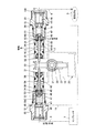
- FIG. 2 is a cross-sectional view of the leveling valve according to the first embodiment of the present invention.
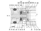
- FIG. 3 is a cross-sectional view of the exhaust valve of the leveling valve according to the first embodiment of the present invention.
- FIG. 4 is an enlarged cross-sectional view of a part of the exhaust valve of the leveling valve according to the first embodiment of the present invention.
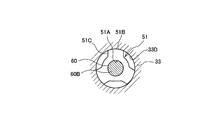
- FIG. 5 is a cross-sectional view showing a VV cross section of FIG.
- FIG. 6 is a cross-sectional view of the exhaust valve of the leveling valve according to the second embodiment of the present invention.
- FIG. 1 is a mounting diagram of a leveling valve according to the first embodiment of the present invention.
- FIG. 2 is a cross-sectional view of the leveling valve according to the first embodiment of the present invention.
- FIG. 3 is a cross-sectional view of the exhaust valve of the leveling valve according to
- FIG. 7 is a cross-sectional view of the exhaust valve of the leveling valve according to the third embodiment of the present invention.
- FIG. 8 is a side view of the valve guide viewed from the direction of arrow B in FIG.
- FIG. 9 is a cross-sectional view of the exhaust valve of the leveling valve according to the fourth embodiment of the present invention.
- FIG. 1 is an attachment diagram of the leveling valve 100 in the present embodiment.
- the leveling valve 100 adjusts the height of the air spring 3 provided between the vehicle body 1 and the carriage 2 of the railway vehicle to maintain the vehicle body 1 at a constant height.
- the leveling valve 100 is mounted between the vehicle body 1 and the carriage 2.
- the leveling valve 100 is attached to the vehicle body 1 and is connected to the carriage 2 via the lever 4 and the connecting rod 5.
- the air spring 3 expands and contracts due to a load change of the vehicle body 1 and the height of the vehicle body 1 changes, this change is transmitted to the leveling valve 100 via the connecting rod 5 and the lever 4.
- the lever 4 When the vehicle body 1 is at a predetermined height with respect to the carriage 2, the lever 4 is in a neutral position, and the air supply valve 31 (see FIG. 2) and the exhaust valve 32 (see FIG. 2) in the leveling valve 100 are both. The valve is kept closed. As a result, the air spring passage 6 communicating with the air spring 3 is blocked from the compressor (compressed air source) 7 and the drain (external), and the air spring 3 is kept at a constant height.
- the lever 4 When the vehicle body load increases and the air spring 3 bends, the lever 4 is pushed upward from the neutral position and rotates in the direction of arrow A in FIG. Along with this, the air supply valve 31 (see FIG. 2) of the leveling valve 100 is opened. As a result, the air spring passage 6 and the compressor 7 communicate with each other, and compressed air from the compressor 7 is supplied to the air spring 3. Thereafter, when the air spring 3 is restored to a certain height, the lever 4 returns to the neutral position, the air supply valve 31 is closed, and the supply of compressed air is shut off.
- the lever 4 when the vehicle body load decreases and the air spring 3 extends, the lever 4 is pulled downward from the neutral position and rotates in the direction of arrow B in FIG. Along with this, the exhaust valve 32 (see FIG. 2) of the leveling valve 100 is opened. Thereby, the air spring passage 6 and the exhaust passage 8 communicate with each other, and the compressed air of the air spring 3 is discharged to the atmosphere. Thereafter, when the air spring 3 is restored to a certain height, the lever 4 returns to the neutral position, the exhaust valve 32 is closed, and the discharge of the compressed air is shut off.
- the leveling valve 100 automatically adjusts the relative displacement generated between the vehicle body 1 and the carriage 2 to maintain the vehicle body 1 at a constant height.
- the leveling valve 100 includes a buffer spring portion 20 disposed at the center, an air supply valve 31 and an exhaust valve 32 disposed at the upper portion, and a damper 25 disposed at the lower portion.
- the buffer spring portion 20 is concentrically incorporated into the shaft 21 with an initial load applied thereto, a swing arm (not shown) fixed to the shaft 21, an operating arm 22 that is rotatable with respect to the shaft 21. And a buffer spring 23 disposed in contact with the swing arm and the operating arm 22 at the same time.
- the rotation of the lever 4 is transmitted to the operating arm 22 through the swing arm and the buffer spring 23. That is, the operating arm 22 rotates as the lever 4 rotates.
- the supply valve 31 and the exhaust valve 32 are arranged symmetrically around the distal end side of the operating arm 22 and are housed in the valve case 11 (see FIG. 1). Since the leveling valve 100 provides a dead zone in which the supply and discharge of compressed air to and from the air spring 3 is prohibited, the air supply valve 31 and the exhaust valve 32 are not immediately opened even when the operating arm 22 rotates from the neutral position. In addition, a gap is provided between the operating arm 22 and the air supply valve 31 and the exhaust valve 32. Accordingly, since the compressed air is not supplied to or discharged from the air spring 3 when the operating arm 22 is rotated less than a predetermined angle, hunting of the air supply valve 31 and the exhaust valve 32 can be prevented.
- the damper 25 includes a piston (not shown) that is connected to the proximal end side of the operating arm 22 and moves as the operating arm 22 rotates.
- the piston is soaked in an oil chamber 12 formed in the valve case 11.
- the piston imparts resistance to the pivoting motion of the actuation arm 22 when the actuation arm 22 pivots from the neutral position, while hardly imparting resistance to the actuation arm 22 when the actuation arm 22 returns to the neutral position. .
- the exhaust valve 32 moves in the axial direction along with the rotation of the operating arm 22, the cylindrical housing 33 attached to the valve case 11, the seat portion 36 that defines the flow path provided inside the housing 33, and the operation arm 22.
- O represents the central axis of the housing 33 and the valve 34.
- radial direction the radial direction around the central axis O
- axial direction the direction in which the central axis O extends
- inside the inner side in the radial direction
- a male screw portion 33F (see FIG. 3) is formed on a part of the outer peripheral surface of the housing 33.
- the housing 33 is fastened to the valve case 11 by screwing the male screw portion 33F with a female screw portion (not shown) formed in the valve case 11.
- a flange portion 33G (see FIG. 3) extending in the radial direction is formed on the outer periphery of the housing 33.
- the housing 33 is positioned with respect to the valve case 11 by the flange portion 33 ⁇ / b> G contacting the end surface of the valve case 11 via the washer 15.
- O-rings 17 to 19 are interposed between the housing 33 and the valve case 11, and the passages 6, 8, and 10 to be described later are sealed.
- a threaded portion 33H is formed on the outer periphery of the protruding portion from the valve case 11 in the housing 33.
- a pipe 6A (see FIG. 1) of the air spring passage 6 is fastened to the threaded portion 33H (see FIG. 3) of the exhaust valve 32.
- a pipe 9 ⁇ / b> A (see FIG. 1) of the supply passage 9 that communicates with the compressor 7 is fastened to the screw portion 33 ⁇ / b> H of the air supply valve 31.
- the housing 33 has, in order from the oil chamber 12 side, larger in comparison with the first hole 33A and the first hole 33A and smaller in diameter with the second hole 33B and the second hole 33B.
- a third hole 33C having a diameter, a fourth hole 33D having a larger diameter compared to the third hole 33C, and a fifth hole 33E having a larger diameter compared to the fourth hole 33D are arranged in series around the central axis O. It is formed.
- the rod 38 is slidably inserted into the inner peripheral surface of the second hole 33B of the housing 33. Thus, the rod 38 is guided so as to be located concentrically with the central axis O.
- the tip of the rod 38 protrudes into the oil chamber 12.
- the valve 34 In a state where the valve 34 is in contact with the seat portion 36, the distal end portion of the rod 38 faces the operating arm 22 with a predetermined gap.
- the operating arm 22 rotates more than a predetermined angle from the neutral position, the operating arm 22 comes into contact with the tip of the rod 38.
- the valve 34 moves against the urging force of the coil spring 39 as the operating arm 22 rotates, and opens away from the seat portion 36.
- the O-ring 14 is interposed at the boundary between the first hole 33A and the second hole 33B of the housing 33.
- the space between the inner peripheral surface of the second hole 33B and the rod 38 is sealed by the O-ring 14.
- the ring-shaped plug 16 is screwed into the first hole 33A of the housing 33 and fastened.
- the plug 16 prevents the O-ring 14 from coming off.
- a first air chamber 45 defined by the third hole 33C, the rod 38, and the valve 34, and a second air defined by the fourth hole 33D, the valve 34, the cap 60, and the valve guide 51 are provided in the housing 33.
- the second air chamber 46, the third air chamber 47, and the fourth air chamber 48 are always in communication with the air spring 3 through the air spring passage 6.
- a drain port 52 that opens to the first air chamber 45 is formed in the housing 33.
- the drain port 52 is always in communication with the outside (drain) through the exhaust passage 8 formed in the valve case 11.
- the housing 33 is formed with a communication port 53 that opens to the second air chamber 46.
- the communication port 53 is always in communication with a supply port 54 (see FIG. 2) formed in the housing 33 of the air supply valve 31 through an annular groove 58 formed in the valve case 11 and the communication passage 10.
- the second air chamber 46, the third air chamber 47, and the fourth air chamber 48 are always in communication with the compressor 7 through the supply passage 9.
- the communication port 53 formed in the housing 33 of the air supply valve 31 is closed by the valve case 11.
- the communication port 53 needs to be formed on the inner peripheral surface of the fourth hole 33D of the housing 33 so as to avoid the male screw portion 33F of the housing 33.
- the annular groove 58 that opens to the inner wall of the valve case 11 needs to be formed so as to avoid a female screw portion (not shown) that is screwed into the male screw portion 33F. For this reason, the communication port 53 cannot be opened to the third air chamber 47 provided inside the male screw portion 33F, and must be opened near the valve 34 of the second air chamber 46.
- the seat part 36 projects in an annular shape in the axial direction from the bottom (step part) 33I of the fourth hole 33D of the housing 33.
- the inner peripheral surface of the sheet portion 36 is continuous with the inner peripheral surface of the third hole 33C without a step.
- the rod 38 has a cylindrical large diameter portion 38A and a cylindrical small diameter portion 38B thinner than the large diameter portion 38A.
- the large diameter portion 38 ⁇ / b> A slides along the second hole 33 ⁇ / b> B of the housing 33.
- the small diameter portion 38B is coupled to the valve 34.
- the valve 34 includes a cylindrical coupling portion 34 ⁇ / b> B coupled to the small diameter portion 38 ⁇ / b> B of the rod 38, and a disc-shaped valve body portion 34 ⁇ / b> A that contacts and separates from the seat portion 36.
- the connecting portion 34B of the valve 34 is fitted to the small diameter portion 38B of the rod 38 at the inner periphery.
- One end of the connecting portion 34B abuts on the step portion 38C of the rod 38, and the other end of the connecting portion 34B is caulked and fixed by the proximal end caulking portion 38D of the rod 38.
- rod 38 and the valve 34 may be integrally formed without being limited to the above-described configuration.
- An annular packing 13 is interposed in the valve body portion 34A. When the packing 13 abuts on the seat portion 36, the sealing performance between the valve body portion 34 ⁇ / b> A and the seat portion 36 is ensured.
- the ring-shaped spring receiving member 41 is provided so as to engage with a step portion 33J formed at the boundary between the fourth hole 33D and the fifth hole 33E (see FIG. 3) of the housing 33.
- the spring receiving member 41 is fixed via a sleeve 42, a perforated plate 43, and a retaining ring 44.
- a coiled spring 39 is interposed between the spring receiving member 41 and the valve guide 51 connected to the valve 34 in a compressed state.
- the spring 39 functions as a biasing member that biases the valve 34 in the valve closing direction in contact with the seat portion 36.
- the valve guide 51 functions as a transmission member that transmits the spring force of the spring 39 to the valve 34.
- the valve guide 51 is a ring-shaped member, and is formed, for example, by punching a flat plate into a ring shape. As shown in FIG. 5, the valve guide 51 includes a connecting hole 51 ⁇ / b> A that fits in a connecting shaft part 60 ⁇ / b> B of the cap 60 described later, an outer peripheral part 51 ⁇ / b> B that slides along the fourth hole 33 ⁇ / b> D of the housing 33, and an outer peripheral part. A plurality of cutouts 51C opening in 51B. Between the cutout 51 ⁇ / b> C and the fourth hole 33 ⁇ / b> D of the housing 33, a flow path is formed through which air supplied to and discharged from the air spring 3 flows.
- the valve guide 51 is slidably inserted into the fourth hole 33D of the housing 33.
- the inner diameter of the fourth hole 33D is formed larger than the outer diameter of the valve guide 51, and a predetermined gap is formed between the outer peripheral portion 51B of the valve guide 51 and the fourth hole 33D.
- the inner peripheral surface of the fourth hole 33D functions as a housing inner wall portion (guide wall) that guides the valve guide 51 so as to move in the axial direction.
- valve guide 51 moves in the axial direction while the outer peripheral portion 51B is in sliding contact with the fourth hole 33D.
- the valve guide 51 functions as a support member that supports the valve 34 so as to be positioned concentrically with the central axis O.
- valve guide 51 in the valve closing position is indicated by a solid line
- valve guide 51 in the valve opening position is indicated by a two-dot chain line.
- the outer peripheral portion 51B of the valve guide 51 moves in the range of the moving region S along the inner peripheral surface of the fourth hole 33D.
- valve guide 51 In order to avoid the outer peripheral portion 51B of the valve guide 51 slidably contacting the inner peripheral surface of the fourth hole 33D from interfering with the communication port 53, the valve guide that separates the valve body portion 34A of the valve 34 and the valve guide 51 in the axial direction.
- a cap 60 as a separation mechanism is interposed between the valve 34 and the valve guide 51.
- the moving region S is set at a position offset in the axial direction with respect to the communication port 53.
- the position of the valve guide 51 is away from the seat portion 36 (on the right side in FIGS. 2 to 4).
- the moving region S in which the outer peripheral portion 51B of the valve guide 51 moves is set at a position away from the opening end of the communication port 53 in the axial direction by arbitrarily setting the axial length of the connecting cylindrical portion 60A in the cap 60. Is done.
- the communication port 53 faces the valve body portion 34 ⁇ / b> A of the valve 34 and the outer periphery of the cap 60.
- the cap 60 includes a connecting tube portion 60A connected to the valve 34, a connecting shaft portion 60B connected to the valve guide 51, and an annular step that contacts the valve guide 51 between the connecting tube portion 60A and the connecting shaft portion 60B. 60C.
- the cap 60 is connected to the valve 34 by fitting the inner periphery of the connecting tube portion 60A to the outer periphery of the connecting portion 34B of the valve 34 and the end surface of the connecting tube portion 60A contacting the stepped portion 34C of the valve 34.
- the valve guide 51 is connected to the valve 34 via the cap 60.
- the end surface of the valve guide 51 is in contact with the step portion 60 ⁇ / b> C of the cap 60 by the spring force of the spring 39.
- the connecting portion 34B of the valve 34 and the connecting shaft portion 60B of the cap 60 are formed so that their outer diameters are equal to each other. Thereby, according to the specification of the exhaust valve 32, when the cap 60 is omitted, the valve guide 51 can be directly connected to the connecting portion 34B of the valve 34.
- a movement region S in which the outer peripheral portion 51B of the valve guide 51 moves along the housing inner wall portion (the inner peripheral surface of the fourth hole 33D) into which the valve guide 51 is slidably inserted is a communication port 53.
- the moving region S can be connected to the communication port without changing the opening position of the communication port 53. 53 can be offset in the axial direction.
- the leveling valve 100 includes a cap 60 interposed between the valve 34 and the valve guide 51, and is arranged so that the communication port 53 faces the outer periphery of the cap 60 in the valve closing position.
- the moving region S can be offset in the axial direction with respect to the communication port 53 without changing the shapes of the valve 34 and the valve guide 51.
- the cap 60 is a ring that contacts the valve guide 51 between the connecting cylinder part 60A connected to the valve 34, the connecting shaft part 60B connected to the valve guide 51, and the connecting cylinder part 60A and the connecting shaft part 60B. Step part 60C.
- region S can be set according to the length of the axial direction of the connection cylinder part 60A.
- FIG. 6 is a cross-sectional view of the exhaust valve 32 of the leveling valve 200 in the present embodiment.
- the same components as those of the leveling valve 100 of the first embodiment will be denoted by the same reference numerals and description thereof will be omitted.
- the cap 60 is interposed between the valve 34 and the valve guide 51.
- the cap 74 is not used, A support portion 74D is provided as a valve guide separation mechanism that supports the valve guide 51 away from the valve body portion 74A.
- the valve 74 includes a disc-shaped valve body portion 74A that contacts the seat portion 36, a cylindrical connection portion 74B to which the valve guide 51 is connected, and a cylindrical shape provided between the valve body portion 74A and the connection portion 74B. Support part 74D.
- the valve body portion 74A, the connecting portion 74B, and the support portion 74D are integrally formed.
- one end surface abuts on the spring 39, and the other end surface abuts on the end portion (stepped portion 74C) of the support portion 74D of the valve 74 by the spring force of the spring 39.
- the support portion 74D is provided in the middle of the valve 74, the position of the valve guide 51 is separated to the side opposite to the seat portion 36 (right side in FIG. 6).
- the moving region S in which the outer peripheral portion 51B of the valve guide 51 moves is offset in the axial direction with respect to the opening end of the communication port 53 by arbitrarily setting the axial length of the support portion 74D.
- the communication port 53 faces the outer periphery of the disc-shaped valve body portion 74 ⁇ / b> A that contacts the seat portion 36 and the support portion 74 ⁇ / b> D.
- the valve 74 has a valve body portion 74A that contacts the seat portion 36, and a support portion 74D that extends in the axial direction from the valve body portion 74A and supports the valve guide 51, and communicates in the valve-closed position.
- the port 53 is disposed so as to face the outer periphery of the support portion 74D. Thereby, the moving region S can be offset in the axial direction with respect to the communication port 53 without changing the shape of the valve guide 51.
- FIG. 7 is a cross-sectional view of the exhaust valve 32 of the leveling valve 300 in the present embodiment.
- FIG. 8 is a side view of the valve guide 81 as seen from the direction of arrow B in FIG.
- differences from the first embodiment will be mainly described, and the same components as those of the leveling valve 100 of the first embodiment will be denoted by the same reference numerals and description thereof will be omitted.
- the cap 60 is interposed between the valve 34 and the valve guide 51.
- the valve guide 81 is provided instead of the cap 60.
- a leg portion 81D is provided as a valve guide separation mechanism that supports the outer peripheral portion 81A away from the valve body portion 34A of the valve 34.
- FIG. 8 is a side view of the valve guide 81 viewed from the direction of arrow B in FIG.
- the valve guide 81 includes a cylindrical leg portion 81D extending in the axial direction, a connection hole 81B that opens to the inside of the leg portion 81D and is connected to the valve 34, and a flange portion 81E that extends in the radial direction from the leg portion 81D. It has the outer peripheral part 81A of the collar part 81E which slides along the 4th hole 33D of the housing 33, and the some notch 81C opened to the outer peripheral part 81A.
- the leg portion 81D, the connecting hole 81B, the flange portion 81E, the outer peripheral portion 81A, and the notch 81C are integrally formed.
- the inner periphery of the connecting hole 81B is fitted to the outer periphery of the connecting portion 34B of the valve 34.
- the end surface of the flange 81E is in contact with the spring, and the end surface of the leg portion 81D of the valve guide 81 is in contact with the step portion 34C (the back surface of the valve body portion 34A) of the valve 34 by the spring force of the spring 39.
- the leg portion 81D is provided so as to extend in the axial direction between the valve body portion 34A of the valve 34 and the outer peripheral portion 81A of the valve guide 81, so that the position of the outer peripheral portion 81A of the valve guide 81 is opposite to the seat portion 36. (Right side in FIG. 7).
- the moving region S in which the outer peripheral portion 81A of the valve guide 81 moves is offset in the axial direction with respect to the opening end of the communication port 53 by arbitrarily setting the axial length of the leg portion 81D.
- the communication port 53 faces the outer periphery of the valve body portion 34 ⁇ / b> A and the leg portion 81 ⁇ / b> D of the valve 34.
- the valve guide 81 has a leg portion 81D that extends in the axial direction and is connected to the valve 34, and the communication port 53 is disposed so as to face the outer periphery of the leg portion 81D in the closed position. Thereby, the moving region S can be offset in the axial direction with respect to the communication port 53 without changing the shape of the valve 34.
- FIG. 9 is a cross-sectional view of the exhaust valve 32 of the leveling valve 400 in the present embodiment.
- the same components as those of the leveling valve 100 of the first embodiment will be denoted by the same reference numerals and description thereof will be omitted.
- the cap 60 is interposed between the valve 34 and the valve guide 51.
- the communication port 53 is used without using the cap 60. The arrangement of was changed.
- the communication port 53 is disposed so as to face the valve body portion 34 ⁇ / b> A of the valve 34 and the outer periphery of the seat portion 36 when the valve 34 is in the valve-closed position in contact with the seat portion 36.
- the movement region S in which the outer peripheral portion 81A of the valve guide 81 moves is set to the opening end of the communication port 53 by arbitrarily setting the protruding height in the axial direction with respect to the bottom portion 33I of the fourth hole 33D of the seat portion 36. Offset in the axial direction.
- the communication port 53 faces the outer periphery of the seat portion 36 and the valve body portion 34 ⁇ / b> A of the valve 34.
- the seat portion 36 is formed in an annular shape extending in the axial direction, and the communication port 53 is disposed so as to face the outer periphery of the valve 34 and the seat portion 36. Thereby, the moving region S can be offset in the axial direction with respect to the communication port 53 without changing the shapes of the valve 34 and the valve guide 81.
Landscapes
- Engineering & Computer Science (AREA)
- General Engineering & Computer Science (AREA)
- Mechanical Engineering (AREA)
- Lift Valve (AREA)
- Multiple-Way Valves (AREA)
- Vehicle Body Suspensions (AREA)
- Mechanically-Actuated Valves (AREA)
- Sliding Valves (AREA)
Abstract
Description
Claims (7)
- 車両の車体と台車との間に設けられる空気バネの高さを調整するレベリングバルブであって、
前記空気バネと圧縮空気源とに連通する流路又は前記空気バネとドレンとに連通する流路を画成するシート部と、
前記台車に対する前記車体の相対変位に応じて軸方向に移動するバルブと、
前記バルブを前記シート部に当接する閉じ側に付勢するスプリングと、
前記スプリングの一端を支持し、ハウジング内壁面に対して摺動自在に挿入されるバルブガイドと、
前記ハウジング内壁面に開口する連通ポートと、
を備え、
前記バルブガイドが移動する移動領域は、前記連通ポートに対して軸方向にオフセットされた位置に設定される、
レベリングバルブ。 - 請求項1に記載のレベリングバルブであって、
前記バルブの前記シート部に当接する弁体部と前記バルブガイドとを前記バルブが移動する軸方向に離間させるバルブガイド離間機構をさらに備える、
レベリングバルブ。 - 請求項2に記載のレベリングバルブであって、
前記バルブガイド離間機構として前記バルブと前記バルブガイドとの間に介装されるキャップを備え、
前記バルブが前記シート部に当接する閉弁位置にある場合、前記連通ポートは、前記キャップの外周に対向するように配置される、
レベリングバルブ。 - 請求項3に記載のレベリングバルブであって、
前記キャップは、前記バルブに連結される連結筒部と、前記バルブガイドに連結される連結軸部と、前記連結筒部と前記連結軸部との間で前記バルブガイドに当接する段部と、を有する、
レベリングバルブ。 - 請求項2に記載のレベリングバルブであって、
前記バルブは、前記バルブガイド離間機構として前記弁体部から軸方向に延びて前記バルブガイドを支持する支持部を有し、
前記バルブが前記シート部に当接する閉弁位置にある場合、前記連通ポートは、前記支持部の外周に対向するように配置される、
レベリングバルブ。 - 請求項2に記載のレベリングバルブであって、
前記バルブガイドは、前記バルブガイド離間機構として軸方向に延びて前記バルブに連結される脚部を有し、
前記バルブが前記シート部に当接する閉弁位置にある場合、前記連通ポートは、前記脚部の外周に対向するように配置される、
レベリングバルブ。 - 請求項1に記載のレベリングバルブであって、
前記シート部は軸方向に延びる環状に形成され、
前記バルブが前記シート部に当接する閉弁位置にある場合、前記連通ポートは、前記バルブの外周及び前記シート部の外周に対向するように配置される、
レベリングバルブ。
Priority Applications (4)
| Application Number | Priority Date | Filing Date | Title |
|---|---|---|---|
| CA2889454A CA2889454C (en) | 2013-02-28 | 2013-12-17 | Leveling valve |
| US14/440,365 US10060542B2 (en) | 2013-02-28 | 2013-12-17 | Leveling valve |
| KR1020157011216A KR101641846B1 (ko) | 2013-02-28 | 2013-12-17 | 레벨링 밸브 |
| CN201380057223.5A CN104755821B (zh) | 2013-02-28 | 2013-12-17 | 调平阀 |
Applications Claiming Priority (2)
| Application Number | Priority Date | Filing Date | Title |
|---|---|---|---|
| JP2013-038978 | 2013-02-28 | ||
| JP2013038978A JP5986941B2 (ja) | 2013-02-28 | 2013-02-28 | レベリングバルブ |
Publications (1)
| Publication Number | Publication Date |
|---|---|
| WO2014132529A1 true WO2014132529A1 (ja) | 2014-09-04 |
Family
ID=51427815
Family Applications (1)
| Application Number | Title | Priority Date | Filing Date |
|---|---|---|---|
| PCT/JP2013/083730 Ceased WO2014132529A1 (ja) | 2013-02-28 | 2013-12-17 | レベリングバルブ |
Country Status (7)
| Country | Link |
|---|---|
| US (1) | US10060542B2 (ja) |
| JP (1) | JP5986941B2 (ja) |
| KR (1) | KR101641846B1 (ja) |
| CN (1) | CN104755821B (ja) |
| CA (1) | CA2889454C (ja) |
| TW (1) | TWI538822B (ja) |
| WO (1) | WO2014132529A1 (ja) |
Families Citing this family (8)
| Publication number | Priority date | Publication date | Assignee | Title |
|---|---|---|---|---|
| US10123189B2 (en) | 2013-03-21 | 2018-11-06 | Razer (Asia-Pacific) Pte. Ltd. | Electronic device system restoration by tapping mechanism |
| US10035523B2 (en) * | 2013-11-26 | 2018-07-31 | Kyb Corporation | Leveling valve |
| JP6709101B2 (ja) * | 2016-04-13 | 2020-06-10 | Kyb株式会社 | レベリングバルブ |
| JP6831116B2 (ja) * | 2018-11-09 | 2021-02-17 | 株式会社不二工機 | 弁装置 |
| WO2020262244A1 (ja) * | 2019-06-26 | 2020-12-30 | 日立オートモティブシステムズ株式会社 | 差圧弁 |
| CN114929548A (zh) * | 2020-01-15 | 2022-08-19 | 日立安斯泰莫株式会社 | 高度调节装置 |
| WO2021201110A1 (ja) * | 2020-04-02 | 2021-10-07 | 愛三工業株式会社 | 流量制御弁 |
| CN114454903B (zh) * | 2022-03-22 | 2023-05-02 | 中车株洲电力机车有限公司 | 一种轨道车辆贯通道排水装置 |
Citations (6)
| Publication number | Priority date | Publication date | Assignee | Title |
|---|---|---|---|---|
| GB931547A (en) * | 1958-11-13 | 1963-07-17 | Dunlop Rubber Co | An improved levelling valve for vehicles with pneumatic or hydraulic suspension |
| JPS4835964B1 (ja) * | 1969-06-27 | 1973-10-31 | ||
| JPS4962865A (ja) * | 1972-10-14 | 1974-06-18 | ||
| JPH06156041A (ja) * | 1992-11-20 | 1994-06-03 | Tokico Ltd | 圧縮空気給排装置 |
| JPH0723605U (ja) * | 1993-10-12 | 1995-05-02 | 三輪精機株式会社 | 車高調整弁 |
| JPH0920123A (ja) * | 1995-07-05 | 1997-01-21 | Hino Motors Ltd | 車高調節装置 |
Family Cites Families (13)
| Publication number | Priority date | Publication date | Assignee | Title |
|---|---|---|---|---|
| US3596679A (en) * | 1969-07-16 | 1971-08-03 | Emerson Electric Co | Manually operable pilot valve |
| JPH08150823A (ja) * | 1994-11-30 | 1996-06-11 | Jidosha Kiki Co Ltd | レベリングバルブ |
| KR100261423B1 (ko) * | 1996-12-31 | 2000-07-01 | 정몽규 | 공기스프링을 사용한 현가장치의 배출공기 회수장치 |
| JP3827187B2 (ja) | 1998-12-17 | 2006-09-27 | カヤバ工業株式会社 | レベリングバルブ |
| JP4130291B2 (ja) | 2000-05-11 | 2008-08-06 | カヤバ工業株式会社 | レベリングバルブ |
| US6382371B1 (en) | 2001-01-26 | 2002-05-07 | Delphi Technologies, Inc. | Self leveling vehicle suspension damper |
| DE10129143C1 (de) | 2001-06-16 | 2002-06-13 | Haldex Brake Prod Gmbh | Pneumatisches Schaltventil für Anlagen zum Heben und Senken des Fahrzeugaufbaus von luftgefederten Fahrzeugen |
| DE10214759A1 (de) * | 2002-04-03 | 2003-10-16 | Lactec Ges Fuer Moderne Lackte | Ventil |
| JP4764117B2 (ja) | 2005-09-14 | 2011-08-31 | 日本車輌製造株式会社 | 鉄道車両 |
| JP5454028B2 (ja) * | 2009-09-09 | 2014-03-26 | いすゞ自動車株式会社 | 方向制御弁装置 |
| DE102009040759A1 (de) * | 2009-09-09 | 2011-03-10 | Wabco Gmbh | Relaisventileinrichtung |
| JP2012031932A (ja) | 2010-07-30 | 2012-02-16 | Hitachi Automotive Systems Ltd | バルブ装置 |
| US9074695B2 (en) * | 2010-09-15 | 2015-07-07 | Fisher Controls International Llc | Volume booster with discrete capacity adjustment |
-
2013
- 2013-02-28 JP JP2013038978A patent/JP5986941B2/ja active Active
- 2013-12-17 KR KR1020157011216A patent/KR101641846B1/ko not_active Expired - Fee Related
- 2013-12-17 CA CA2889454A patent/CA2889454C/en not_active Expired - Fee Related
- 2013-12-17 CN CN201380057223.5A patent/CN104755821B/zh active Active
- 2013-12-17 US US14/440,365 patent/US10060542B2/en active Active
- 2013-12-17 WO PCT/JP2013/083730 patent/WO2014132529A1/ja not_active Ceased
-
2014
- 2014-01-13 TW TW103101128A patent/TWI538822B/zh not_active IP Right Cessation
Patent Citations (6)
| Publication number | Priority date | Publication date | Assignee | Title |
|---|---|---|---|---|
| GB931547A (en) * | 1958-11-13 | 1963-07-17 | Dunlop Rubber Co | An improved levelling valve for vehicles with pneumatic or hydraulic suspension |
| JPS4835964B1 (ja) * | 1969-06-27 | 1973-10-31 | ||
| JPS4962865A (ja) * | 1972-10-14 | 1974-06-18 | ||
| JPH06156041A (ja) * | 1992-11-20 | 1994-06-03 | Tokico Ltd | 圧縮空気給排装置 |
| JPH0723605U (ja) * | 1993-10-12 | 1995-05-02 | 三輪精機株式会社 | 車高調整弁 |
| JPH0920123A (ja) * | 1995-07-05 | 1997-01-21 | Hino Motors Ltd | 車高調節装置 |
Also Published As
| Publication number | Publication date |
|---|---|
| TW201437063A (zh) | 2014-10-01 |
| KR20150067243A (ko) | 2015-06-17 |
| JP2014167319A (ja) | 2014-09-11 |
| KR101641846B1 (ko) | 2016-07-21 |
| CA2889454C (en) | 2017-06-27 |
| CN104755821B (zh) | 2016-09-07 |
| US10060542B2 (en) | 2018-08-28 |
| JP5986941B2 (ja) | 2016-09-06 |
| TWI538822B (zh) | 2016-06-21 |
| US20150285388A1 (en) | 2015-10-08 |
| CA2889454A1 (en) | 2014-09-04 |
| CN104755821A (zh) | 2015-07-01 |
Similar Documents
| Publication | Publication Date | Title |
|---|---|---|
| WO2014132529A1 (ja) | レベリングバルブ | |
| JP5009107B2 (ja) | サックバックバルブ | |
| WO2018061726A1 (ja) | 減衰力調整式緩衝器 | |
| CN104343881A (zh) | 缓冲器 | |
| CN108071828B (zh) | 减压阀装置 | |
| EP3351820A1 (en) | Damper | |
| JP6353853B2 (ja) | レベリングバルブ | |
| JP6200523B2 (ja) | ピストン・シリンダユニット | |
| JP2016508587A (ja) | オーバーフロー弁 | |
| WO2017204068A1 (ja) | ガススプリング装置 | |
| JP2013079692A (ja) | 流量制御弁 | |
| KR20200002977A (ko) | 완충기 | |
| JP2022181783A (ja) | 複合バルブ装置 | |
| JP5014049B2 (ja) | ダンパー装置 | |
| JP4199684B2 (ja) | ラッシュアジャスタ | |
| JP7487086B2 (ja) | 緩衝器 | |
| TWI526350B (zh) | Horizontal valve | |
| JP2017089703A (ja) | ピストン機構 | |
| CN117989330A (zh) | 电子膨胀阀 | |
| JP2012017805A (ja) | ガス栓 | |
| JP2009024818A (ja) | ショックアブソーバー | |
| JP2009243141A (ja) | 閉扉速度調整装置及びドアクローザ | |
| JP2008014340A (ja) | 油圧式オートテンショナ | |
| JP2008064273A (ja) | 油圧式オートテンショナ | |
| JPH0635547A (ja) | 圧力制御弁装置 |
Legal Events
| Date | Code | Title | Description |
|---|---|---|---|
| 121 | Ep: the epo has been informed by wipo that ep was designated in this application |
Ref document number: 13876700 Country of ref document: EP Kind code of ref document: A1 |
|
| ENP | Entry into the national phase |
Ref document number: 2889454 Country of ref document: CA |
|
| ENP | Entry into the national phase |
Ref document number: 20157011216 Country of ref document: KR Kind code of ref document: A |
|
| WWE | Wipo information: entry into national phase |
Ref document number: 14440365 Country of ref document: US |
|
| NENP | Non-entry into the national phase |
Ref country code: DE |
|
| 122 | Ep: pct application non-entry in european phase |
Ref document number: 13876700 Country of ref document: EP Kind code of ref document: A1 |