WO2014115428A1 - 伸縮アームおよび伸縮アームを用いた構造物 - Google Patents
伸縮アームおよび伸縮アームを用いた構造物 Download PDFInfo
- Publication number
- WO2014115428A1 WO2014115428A1 PCT/JP2013/082655 JP2013082655W WO2014115428A1 WO 2014115428 A1 WO2014115428 A1 WO 2014115428A1 JP 2013082655 W JP2013082655 W JP 2013082655W WO 2014115428 A1 WO2014115428 A1 WO 2014115428A1
- Authority
- WO
- WIPO (PCT)
- Prior art keywords
- telescopic arm
- arm
- telescopic
- rigid member
- shape
- Prior art date
- Legal status (The legal status is an assumption and is not a legal conclusion. Google has not performed a legal analysis and makes no representation as to the accuracy of the status listed.)
- Ceased
Links
Images


Classifications
-
- F—MECHANICAL ENGINEERING; LIGHTING; HEATING; WEAPONS; BLASTING
- F16—ENGINEERING ELEMENTS AND UNITS; GENERAL MEASURES FOR PRODUCING AND MAINTAINING EFFECTIVE FUNCTIONING OF MACHINES OR INSTALLATIONS; THERMAL INSULATION IN GENERAL
- F16M—FRAMES, CASINGS OR BEDS OF ENGINES, MACHINES OR APPARATUS, NOT SPECIFIC TO ENGINES, MACHINES OR APPARATUS PROVIDED FOR ELSEWHERE; STANDS; SUPPORTS
- F16M13/00—Other supports for positioning apparatus or articles; Means for steadying hand-held apparatus or articles
- F16M13/02—Other supports for positioning apparatus or articles; Means for steadying hand-held apparatus or articles for supporting on, or attaching to, an object, e.g. tree, gate, window-frame, cycle
- F16M13/022—Other supports for positioning apparatus or articles; Means for steadying hand-held apparatus or articles for supporting on, or attaching to, an object, e.g. tree, gate, window-frame, cycle repositionable
-
- A—HUMAN NECESSITIES
- A47—FURNITURE; DOMESTIC ARTICLES OR APPLIANCES; COFFEE MILLS; SPICE MILLS; SUCTION CLEANERS IN GENERAL
- A47B—TABLES; DESKS; OFFICE FURNITURE; CABINETS; DRAWERS; GENERAL DETAILS OF FURNITURE
- A47B23/00—Bed-tables; Trays; Reading-racks; Book-rests, i.e. items used in combination with something else
- A47B23/007—Overhead reading-racks or book-rests
-
- A—HUMAN NECESSITIES
- A47—FURNITURE; DOMESTIC ARTICLES OR APPLIANCES; COFFEE MILLS; SPICE MILLS; SUCTION CLEANERS IN GENERAL
- A47B—TABLES; DESKS; OFFICE FURNITURE; CABINETS; DRAWERS; GENERAL DETAILS OF FURNITURE
- A47B23/00—Bed-tables; Trays; Reading-racks; Book-rests, i.e. items used in combination with something else
- A47B23/02—Bed-tables; Trays; Reading-racks; Book-rests, i.e. items used in combination with something else releasably mounted on the bedstead or another item of furniture
- A47B23/025—Bed-tables; Trays; Reading-racks; Book-rests, i.e. items used in combination with something else releasably mounted on the bedstead or another item of furniture mounted on the bedstead
-
- A—HUMAN NECESSITIES
- A47—FURNITURE; DOMESTIC ARTICLES OR APPLIANCES; COFFEE MILLS; SPICE MILLS; SUCTION CLEANERS IN GENERAL
- A47C—CHAIRS; SOFAS; BEDS
- A47C21/00—Attachments for beds, e.g. sheet holders or bed-cover holders; Ventilating, cooling or heating means in connection with bedsteads or mattresses
- A47C21/003—Lighting, radio, telephone or the like connected to the bedstead
-
- A—HUMAN NECESSITIES
- A63—SPORTS; GAMES; AMUSEMENTS
- A63H—TOYS, e.g. TOPS, DOLLS, HOOPS OR BUILDING BLOCKS
- A63H33/00—Other toys
-
- B—PERFORMING OPERATIONS; TRANSPORTING
- B25—HAND TOOLS; PORTABLE POWER-DRIVEN TOOLS; MANIPULATORS
- B25J—MANIPULATORS; CHAMBERS PROVIDED WITH MANIPULATION DEVICES
- B25J18/00—Arms
- B25J18/02—Arms extensible
-
- F—MECHANICAL ENGINEERING; LIGHTING; HEATING; WEAPONS; BLASTING
- F16—ENGINEERING ELEMENTS AND UNITS; GENERAL MEASURES FOR PRODUCING AND MAINTAINING EFFECTIVE FUNCTIONING OF MACHINES OR INSTALLATIONS; THERMAL INSULATION IN GENERAL
- F16M—FRAMES, CASINGS OR BEDS OF ENGINES, MACHINES OR APPARATUS, NOT SPECIFIC TO ENGINES, MACHINES OR APPARATUS PROVIDED FOR ELSEWHERE; STANDS; SUPPORTS
- F16M11/00—Stands or trestles as supports for apparatus or articles placed thereon ; Stands for scientific apparatus such as gravitational force meters
- F16M11/02—Heads
- F16M11/04—Means for attachment of apparatus; Means allowing adjustment of the apparatus relatively to the stand
- F16M11/06—Means for attachment of apparatus; Means allowing adjustment of the apparatus relatively to the stand allowing pivoting
- F16M11/10—Means for attachment of apparatus; Means allowing adjustment of the apparatus relatively to the stand allowing pivoting around a horizontal axis
-
- F—MECHANICAL ENGINEERING; LIGHTING; HEATING; WEAPONS; BLASTING
- F16—ENGINEERING ELEMENTS AND UNITS; GENERAL MEASURES FOR PRODUCING AND MAINTAINING EFFECTIVE FUNCTIONING OF MACHINES OR INSTALLATIONS; THERMAL INSULATION IN GENERAL
- F16M—FRAMES, CASINGS OR BEDS OF ENGINES, MACHINES OR APPARATUS, NOT SPECIFIC TO ENGINES, MACHINES OR APPARATUS PROVIDED FOR ELSEWHERE; STANDS; SUPPORTS
- F16M11/00—Stands or trestles as supports for apparatus or articles placed thereon ; Stands for scientific apparatus such as gravitational force meters
- F16M11/20—Undercarriages with or without wheels
- F16M11/2007—Undercarriages with or without wheels comprising means allowing pivoting adjustment
- F16M11/2014—Undercarriages with or without wheels comprising means allowing pivoting adjustment around a vertical axis
-
- F—MECHANICAL ENGINEERING; LIGHTING; HEATING; WEAPONS; BLASTING
- F16—ENGINEERING ELEMENTS AND UNITS; GENERAL MEASURES FOR PRODUCING AND MAINTAINING EFFECTIVE FUNCTIONING OF MACHINES OR INSTALLATIONS; THERMAL INSULATION IN GENERAL
- F16M—FRAMES, CASINGS OR BEDS OF ENGINES, MACHINES OR APPARATUS, NOT SPECIFIC TO ENGINES, MACHINES OR APPARATUS PROVIDED FOR ELSEWHERE; STANDS; SUPPORTS
- F16M11/00—Stands or trestles as supports for apparatus or articles placed thereon ; Stands for scientific apparatus such as gravitational force meters
- F16M11/20—Undercarriages with or without wheels
- F16M11/2092—Undercarriages with or without wheels comprising means allowing depth adjustment, i.e. forward-backward translation of the head relatively to the undercarriage
-
- F—MECHANICAL ENGINEERING; LIGHTING; HEATING; WEAPONS; BLASTING
- F16—ENGINEERING ELEMENTS AND UNITS; GENERAL MEASURES FOR PRODUCING AND MAINTAINING EFFECTIVE FUNCTIONING OF MACHINES OR INSTALLATIONS; THERMAL INSULATION IN GENERAL
- F16M—FRAMES, CASINGS OR BEDS OF ENGINES, MACHINES OR APPARATUS, NOT SPECIFIC TO ENGINES, MACHINES OR APPARATUS PROVIDED FOR ELSEWHERE; STANDS; SUPPORTS
- F16M11/00—Stands or trestles as supports for apparatus or articles placed thereon ; Stands for scientific apparatus such as gravitational force meters
- F16M11/20—Undercarriages with or without wheels
- F16M11/24—Undercarriages with or without wheels changeable in height or length of legs, also for transport only, e.g. by means of tubes screwed into each other
- F16M11/38—Undercarriages with or without wheels changeable in height or length of legs, also for transport only, e.g. by means of tubes screwed into each other by folding, e.g. pivoting or scissors tong mechanisms
-
- F—MECHANICAL ENGINEERING; LIGHTING; HEATING; WEAPONS; BLASTING
- F16—ENGINEERING ELEMENTS AND UNITS; GENERAL MEASURES FOR PRODUCING AND MAINTAINING EFFECTIVE FUNCTIONING OF MACHINES OR INSTALLATIONS; THERMAL INSULATION IN GENERAL
- F16M—FRAMES, CASINGS OR BEDS OF ENGINES, MACHINES OR APPARATUS, NOT SPECIFIC TO ENGINES, MACHINES OR APPARATUS PROVIDED FOR ELSEWHERE; STANDS; SUPPORTS
- F16M13/00—Other supports for positioning apparatus or articles; Means for steadying hand-held apparatus or articles
- F16M13/02—Other supports for positioning apparatus or articles; Means for steadying hand-held apparatus or articles for supporting on, or attaching to, an object, e.g. tree, gate, window-frame, cycle
-
- F—MECHANICAL ENGINEERING; LIGHTING; HEATING; WEAPONS; BLASTING
- F21—LIGHTING
- F21V—FUNCTIONAL FEATURES OR DETAILS OF LIGHTING DEVICES OR SYSTEMS THEREOF; STRUCTURAL COMBINATIONS OF LIGHTING DEVICES WITH OTHER ARTICLES, NOT OTHERWISE PROVIDED FOR
- F21V21/00—Supporting, suspending, or attaching arrangements for lighting devices; Hand grips
- F21V21/14—Adjustable mountings
- F21V21/24—Lazy-tongs
-
- F—MECHANICAL ENGINEERING; LIGHTING; HEATING; WEAPONS; BLASTING
- F21—LIGHTING
- F21V—FUNCTIONAL FEATURES OR DETAILS OF LIGHTING DEVICES OR SYSTEMS THEREOF; STRUCTURAL COMBINATIONS OF LIGHTING DEVICES WITH OTHER ARTICLES, NOT OTHERWISE PROVIDED FOR
- F21V21/00—Supporting, suspending, or attaching arrangements for lighting devices; Hand grips
- F21V21/14—Adjustable mountings
- F21V21/26—Pivoted arms
-
- F—MECHANICAL ENGINEERING; LIGHTING; HEATING; WEAPONS; BLASTING
- F16—ENGINEERING ELEMENTS AND UNITS; GENERAL MEASURES FOR PRODUCING AND MAINTAINING EFFECTIVE FUNCTIONING OF MACHINES OR INSTALLATIONS; THERMAL INSULATION IN GENERAL
- F16M—FRAMES, CASINGS OR BEDS OF ENGINES, MACHINES OR APPARATUS, NOT SPECIFIC TO ENGINES, MACHINES OR APPARATUS PROVIDED FOR ELSEWHERE; STANDS; SUPPORTS
- F16M2200/00—Details of stands or supports
- F16M2200/06—Arms
- F16M2200/061—Scissors arms
-
- F—MECHANICAL ENGINEERING; LIGHTING; HEATING; WEAPONS; BLASTING
- F21—LIGHTING
- F21S—NON-PORTABLE LIGHTING DEVICES; SYSTEMS THEREOF; VEHICLE LIGHTING DEVICES SPECIALLY ADAPTED FOR VEHICLE EXTERIORS
- F21S6/00—Lighting devices intended to be free-standing
-
- F—MECHANICAL ENGINEERING; LIGHTING; HEATING; WEAPONS; BLASTING
- F21—LIGHTING
- F21W—INDEXING SCHEME ASSOCIATED WITH SUBCLASSES F21K, F21L, F21S and F21V, RELATING TO USES OR APPLICATIONS OF LIGHTING DEVICES OR SYSTEMS
- F21W2121/00—Use or application of lighting devices or systems for decorative purposes, not provided for in codes F21W2102/00 – F21W2107/00
- F21W2121/04—Use or application of lighting devices or systems for decorative purposes, not provided for in codes F21W2102/00 – F21W2107/00 for Christmas trees
Definitions
- the present invention relates to a telescopic arm, and more particularly to a telescopic arm in which a plurality of X-shaped cross units are connected in one direction and rotatably connected to each other.
- the telescopic arm is widely used in various industrial devices such as an industrial robot arm, a lamp stand, and an arm supporting a table on which an object is placed, life related devices, medical related devices, and the like.
- One of the typical telescopic arms crosses two linearly extending plate members in an X-shape at their respective central portions, and is pivotally connected at the intersection point via an axis to form a cross unit A plurality of the cross units are arranged in one direction and rotatably connected to each other.
- the telescopic arm having such a structure can be telescopic along a linear direction.
- the telescopic arm may be stretched in a curvilinear direction.
- a telescopic arm capable of expanding and contracting in a curvilinear direction is disclosed in Japanese Utility Model Application Laid-Open No. 1-159036 (Patent Document 1) and Japanese Patent Application Publication No. 2006-52603 (Patent Document 2).
- the telescopic arm disclosed in Japanese Utility Model Application Laid-Open No. 1-159036 (Patent Document 1) is used for a front-winding movable tent in which a tent is developed while drawing a curve on the way.
- Patent Document 1 Japanese Utility Model Application Laid-Open No. 1-159036
- a tent is attached between the base rod and the rotatably mounted front rod, and the above-described front rod is rotatably mounted between the tips of the telescopic arms.
- the front rod is connected to a motor to reverse it forward and reverse.
- the telescopic arm is formed by connecting a plurality of cross units in which two linear plate members are crossed in an X-shape so as to be rotatable along one direction.
- the deployed tent site has a curved area on the way.
- the cross unit located in the curve area is provided at a position where the cross axis connecting the two plate members is offset from the center so as to follow the development path of such a tent site. Since the length from the cross axis to the outer end of each plate member is larger than the length from the cross axis to the inner end of each plate member, each plate can be expanded by connecting a plurality of connected cross units.
- the phantom lines connecting the outer ends of the units are curved with a relatively large radius of curvature, and the phantom lines connecting the inner ends of each plate unit are curved with a relatively small radius of curvature.
- FIG. 12 of JP-A-2006-52603 shows a slide type multistage stretchable structure having an arch shape curved with a predetermined curvature radius.
- the telescopic structure is one in which a telescopic mechanism including a continuous cross unit is disposed between a pair of cylindrical arms. Each cylindrical arm is slidably fitted with a plurality of curved tube-shaped cylinders to form an arch shape when extended. Both ends in the width direction of the extension mechanism including the cross unit are rotatably connected to the respective tubular arms.
- a curved shape is formed by providing the cross axis of the cross unit at a position shifted from the center of the plate member.
- the length from the cross axis to the outer end of the cross unit is longer than the length from the inner end, so that the structure is unbalanced.
- the cross unit is one in which two linear plate members are crossed at the central portion and connected, and structurally balanced It has become a good thing.
- the telescopic arm in which the cross unit is connected in one direction expands and contracts in a linear direction, but since both ends are connected to a curved tubular cylindrical slide arm that forms an arch shape in the unfolded state. An unreasonable force generated by an inherent difference in operation is applied to each member constituting the telescopic arm.
- the present invention has been made to solve the above-mentioned problems, and an object thereof is to provide a telescopic arm capable of forming a curved shape with a structure well balanced and in which no excessive force acts. It is.
- two rigid members are pivotally connected at a central connection point to form a cross unit crossing in an X shape, and a plurality of the cross units are connected in one direction to each other. It has a structure connected rotatably with respect to each other.
- Each rigid member is positioned such that the connection points at both ends thereof are offset from the longitudinal axis with respect to the longitudinal axis passing through the central connection point such that the expansion and contraction locus of the expansion and contraction arm draws a curved line.
- connection points at both ends of the rigid member are offset in the width direction of the rigid member. In another embodiment, the connection points at both ends of the rigid member are offset in the thickness direction of the rigid member. In this case, preferably, in the rigid member, the thickness direction axis passing through the central connection point of the rigid member and the thickness direction axis passing through the connection points at both ends are along the thickness direction axis passing through the central connection point Converge, has a curved shape.
- the rigid member is curved with a uniform radius of curvature throughout its longitudinal direction. In another embodiment, the rigid member has a linear shape in its central longitudinal area.
- a three-dimensional object may be made using the above-mentioned telescopic arm.
- the three-dimensional shape developed from the telescopic arm forms a surface selected from the group consisting of a cylindrical surface, a conical surface and a spherical surface.
- the three-dimensional shape developed from the telescopic arm forms a shape selected from the group consisting of an arc shape, a spiral shape, an arch shape and a wave shape.
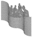
- An example of a three-dimensional object is a partition formed by connecting a plurality of telescopic arms in the width direction intersecting the longitudinal direction.
- An electric stand comprises a telescopic arm and a lighting lamp attached to the tip of the telescopic arm.
- the telescopic arm connects two rigid members rotatably at a central connection point to form an X-shaped crossed cross unit, connects a plurality of such cross units in one direction and rotates relative to each other It is linked possible.
- Each rigid member is positioned such that the connection points at both ends thereof are offset from the longitudinal axis with respect to the longitudinal axis passing through the central connection point so that the expansion and contraction locus of the extendable arm draws a curved line. It has a curved shape.
- connection points at both ends of the rigid member are offset in the width direction of the rigid member, and the illumination direction of the illumination lamp is constant without being influenced by the expansion and contraction state of the extendable arm.
- connection points at both ends of the rigid member are offset in the thickness direction of the rigid member, and the illumination lamp illuminates the same position without being influenced by the expansion and contraction state of the extendable arm.
- the desk lamp includes a base member that supports the proximal end of the extendable arm and includes a power control and an electrical cord extending from the base member to the illumination lamp.
- the electrical cord passes within the thickness range of the telescopic arm.
- the bed structure with telescopic arms is a bed and, in an extended state, it is greatly curved from the side of the bed to above the face of a person sleeping on the bed.
- a telescopic arm extending in shape and an article holding holder attached to the telescopic arm.
- the telescopic arm connects two rigid members rotatably at a central connection point to form an X-shaped crossed cross unit, connects a plurality of such cross units in one direction and rotates relative to each other It is linked possible.
- Each rigid member is positioned such that the connection points at both ends thereof are offset from the longitudinal axis with respect to the longitudinal axis passing through the central connection point so that the expansion and contraction locus of the extendable arm draws a curved line. It has a curved shape.
- connection points at both ends of the rigid member are offset in the thickness direction of the rigid member.
- the article holding holding member holds the visual object.
- the held visual object always provides a visual surface facing the face of the person sleeping on the bed, without being influenced by the telescopic state of the telescopic arm.
- visual objects are typically televisions, displays, etc., in the present specification, audio-visual objects and audio-visual objects that generate sound are also included in the category of “visual objects”. Intended.
- the telescopic arm bed structure includes, for example, a base member fixed to the bed, and the proximal end of the telescopic arm is rotatably supported by the base member.
- the connecting structure of the telescopic arm and the article holding member is configured such that the angle of the article holding member relative to the longitudinal axis of the telescopic arm changes according to the telescopic movement of the telescopic arm.
- one rigid member located at the distal end of the telescopic arm is angularly fixedly connected to the article holding retaining member, and the angle of the article holding retaining member relative to the longitudinal axis of the telescopic arm is , It changes according to the extension length of the extension arm.
- An article holding device is extendable, and in an extended state, includes an extendable arm extending in a greatly curved shape, and an article holding holder attached to the extendable arm.
- the telescopic arm connects two rigid members rotatably at a central connection point to form an X-shaped crossed cross unit, connects a plurality of such cross units in one direction and rotates relative to each other It is linked possible.
- Each rigid member is positioned such that the connection points at both ends thereof are offset from the longitudinal axis with respect to the longitudinal axis passing through the central connection point so that the expansion and contraction locus of the extendable arm draws a curved line. It has a curved shape.
- each rigid member constituting the cross unit connects the both ends with respect to the longitudinal axis passing through the central connection point so that the telescopic locus of the telescopic arm draws a curved line. Since the point has a curved shape that is shifted from the longitudinal axis to one side, the curved shape can be formed with a good balance and a structure in which no excessive force acts.
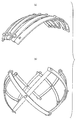
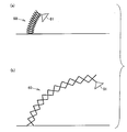
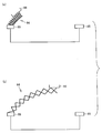
- FIG. 1 It is a figure showing a rigid member which constitutes an extendable arm concerning a 1st embodiment, (a) is a top view, (b) is a front view, (c) is a CC sectional view line. It is a top view of the expansion-contraction arm which concerns on 2nd Embodiment of this invention, and has shown the contracted state. It is a front view of the extendable arm concerning a 2nd embodiment, and has shown the contracted state. It is a perspective view of the extendable arm concerning a 2nd embodiment, and has shown the extended state.
- FIG. 1 It is a figure which shows the rigid member which comprises the expansion-contraction arm which concerns on 2nd Embodiment, (a) is a top view, (b) is a front view, (c) is a CC sectional view taken on the line. It is a top view of the extendable arm concerning a 3rd embodiment of the present invention, and has shown the contracted state. It is a front view of the extendable arm concerning a 3rd embodiment, and has shown the contracted state. It is a perspective view of the extendable arm concerning a 3rd embodiment, and has shown the state where it extended a little. It is a perspective view of an extendable arm concerning a 3rd embodiment, and has shown the state where it extended relatively large.
- FIG. 5 is a cross-sectional view of a rigid member having a central longitudinal region in a straight line shape and curved in a thickness direction as a whole. It is a top view of a rigid member curving with a uniform curvature radius in the width direction.
- FIG. 5 is a plan view of a rigid member having a central longitudinal region that is linear and generally curved in the width direction.
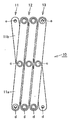
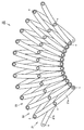
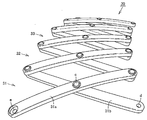
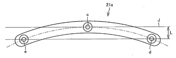
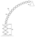
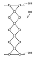
- the extendable arm 10 has a structure in which a plurality of cross units 11, 12, 13 are connected in one direction and rotatably connected to each other. Since the plurality of cross units 11, 12, 13 have the same structure, one cross unit 11 will be representatively described in order to avoid duplication.
- two rigid members 11a and 11b are rotatably connected at a central connection point c and intersected in an X shape.
- Let d and e be connection points at both ends of each of the rigid members 11a and 11b.
- Each of the rigid members 11a and 11b has connection points d and e at both ends from the longitudinal axis with respect to the longitudinal axis passing through the central connection point c so that the expansion and contraction trajectory of the extendable arm 10 draws a curved line. It has a curved shape that is shifted to one side.
- the distance between the central connection point c and the connection point d at one end is the same as the distance between the central connection point c and the connection point e at the other end.
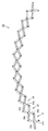
- each rigid member 11a has a linear shape in a plan view, but a uniform radius of curvature over the entire longitudinal direction in a front view Curving.
- the curve is exaggerated and shown in figure.
- Each rigid member 11a is curved in the thickness direction, and the two end connection points d and e are separated by a distance to one side in the thickness direction with respect to the longitudinal axis J extending longitudinally in a straight line through the central connection point c. The position is shifted by L. As shown in FIG.
- each rigid member 11a has a thickness direction axis T1 passing through the central connection point c of the rigid member 11a and a thickness direction axis T2 passing through the connection points d and e at both ends.
- T3 have a curved shape that converges on the thickness direction axis T1 passing through the central connection point c.
- the thickness direction axis at each connection point coincides with the axial direction of the shaft that rotatably connects two rigid members intersecting at the connection point.
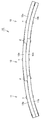
- the extendable arm 10 in a plan view, it is in a linearly extended state.
- it in front view as shown in FIG. 4, it has a shape which is curved and extended in the thickness direction with a uniform radius of curvature.
- the radius of curvature of the curved surface in the extended state is approximately the same as the radius of curvature of each rigid member 11a.
- FIG. 17 shows another example of the rigid member used for the telescopic arm that is curved in the thickness direction.
- the longitudinal direction central region of the rigid member 110 shown in FIG. 17 has a linear shape, and both end portions are curved in the thickness direction to form a curved shape as a whole. Even in the case of the rigid member shown in FIG. 17, the three thickness direction axes passing through the central connection point c and the both end connection points d and e are converged at one point.
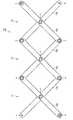
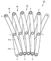
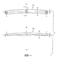
- the extendable arm 20 has a structure in which a plurality of cross units 21, 22, 23 are connected in one direction and rotatably connected to each other.
- the cross unit 21 has two rigid members 21a and 21b which are curved in a plan view, that is, curved in the width direction, are pivotably connected at the central connection point c and intersect in an X shape I am doing it.
- the direction of curvature of the one rigid member 21a and the other rigid member 21b are reversed.
- one rigid member 21 a has a curved shape that is convex to the left
- the other rigid member 21 b has a curved shape that is convex to the right.
- the distance between the two rigid members 21a and 21b at one end of the cross unit 21 is two at the other end (the end located at the bottom in FIG. 7)
- the distance between the rigid members 21a and 21b is greater than the distance between the rigid members 21a and 21b.
- each of the rigid members 21a and 21b has a curved shape (a shape curved in the width direction) in a plan view of (a), but has a uniform thickness in a front view of (b) In the shape of a straight line. Therefore, as shown in FIG. 8, in the telescopic arm 20 in which the plurality of cross units 21, 22, 23 are connected, the upper surface and the lower surface in the thickness direction are flat and parallel, respectively. It is a relationship.
- the extendable arm 20 forms a large curved shape in the width direction without changing the thickness in the thickness direction.
- connection points d and e at both ends are longitudinal axes J extending linearly and longitudinally through the central connection point.
- the distance L is shifted to one side in the width direction.
- the rigid member 21a is curved with a uniform radius of curvature throughout its longitudinal direction.
- FIG. 19 shows another example of the rigid member used for the telescopic arm that is curved in the width direction.
- the longitudinal direction central region of the rigid member 210 shown in FIG. 19 has a linear shape, and both end portions are curved in the width direction to have a curved shape as a whole. Even in the case of the rigid member shown in FIG. 19, the lines passing through the central connection point c and the both end connection points d and e have a curved shape.
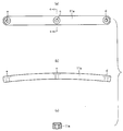
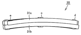
- the telescopic arm 30 according to this embodiment is, as in the embodiments described above, formed by connecting a plurality of cross units 31, 32, 33 in one direction and rotatably relative to each other.
- Each of the rigid members 31a and 31b constituting the cross unit 31 has one longitudinal axis from the longitudinal axis at which the connection points d and e at both ends pass through the central connection point c so that the expansion and contraction locus of the expansion and contraction arm 30 draws a curved line. It is in the wrong position.
- Each rigid member 31a, 31b according to this embodiment is curved in the thickness direction and also has a shape curved in the width direction.
- FIG. 15 (a) is a plan view of one rigid member 31a. As illustrated, the longitudinal axis J1 passing through the end connection points d and e in the plan view is offset from the longitudinal axis J2 passing through the central connection point c by a distance L1.
- one rigid member 31a has a curved shape convex to the right
- the other rigid member 31b has a curved shape convex to the left. Therefore, the distance between the two rigid members 31a and 31b at one end (upper side in the drawing) of the cross unit 31 is larger than the distance between the two rigid members 31a and 31b at the other end (lower side in the drawing)
- the whole of the extendable arm 30 has a curved shape that is convex upward.
- each of the rigid members 31a, 31b has a curved shape in the thickness direction.
- the longitudinal axis J3 passing through both end connection points d and e is deviated from the longitudinal axis J4 passing through the central connection point c by a distance L2.
- the rigid member 31a has a shape in which both end connection points d and e project in the width direction, that is, a shape curved in the width direction. It is uniformly curved with a constant radius of curvature throughout the length direction. Further, as shown in FIG. 15B, the rigid member 31a has a shape in which both end connection points d and e protrude in the thickness direction, that is, a shape curved in the thickness direction, but the entire length direction Uniformly curved with a constant radius of curvature.
- FIG. 13 shows the telescopic arm 30 in a slightly extended state
- FIG. 14 shows the telescopic arm 30 in a greatly extended state
- the telescopic arm 30 in the extended state has a curved shape with a central portion convex in the width direction in a plan view as viewed from above, and a central portion in a front view as viewed from the front. It has a curved shape. It is also possible to configure the telescopic arm 30 in the unfolded state so as to form a part of a substantially conical surface by appropriately changing the degree of bending and also changing the entire length as appropriate.
- FIG. 20 shows a telescopic arm 40 according to a fourth embodiment of the present invention.
- Each rigid member 41a, 41b which comprises the cross unit 41 of the expansion-contraction arm 40 is not curved in the thickness direction, but has a shape curved only in the width direction.
- the telescopic arm 40 according to this embodiment has a structure in which a pair of cross units 41 having the same structure are spaced apart in the thickness direction, and a spacer 46 is provided to keep a space between them.
- the spacers 46 are located at the connection points c, d and e.
- FIG. 21 shows a telescopic arm 50 according to a fifth embodiment of the present invention.
- Each rigid member 51a, 51b which comprises the cross unit 51 of the expansion-contraction arm 50 is not curved in the thickness direction, but has a shape curved only in the width direction.
- One rigid member 51a is provided in a pair at intervals in the thickness direction, and the other rigid member 51b is attached by being sandwiched between the pair of rigid members 51a.
- the telescopic arm 40 shown in FIG. 20 and the telescopic arm 50 shown in FIG. 21 have a structure in which at least one rigid member is provided in a pair, they are excellent in strength.
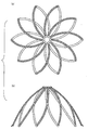
- the arc shape, spiral shape, wave shape, etc. can be freely made by devising the shapes of the respective rigid members or combining the cross units consisting of rigid members of different shapes as appropriate. It can be designed. It is also possible to make the three-dimensional shape in which the telescopic arm is developed form a part of a cylindrical surface, a part of a conical surface, or a part of a spherical surface. Telescopic arms that extend and retract in a curved configuration are available for many applications.
- FIG. 22 shows an embodiment configured to draw an S-shaped curved line when the telescopic arm is deployed.
- 22 (a) is a plan view
- FIG. 22 (b) is a front view.
- each rigid member has a slightly curved shape in the thickness direction except for the cross unit CX located at the middle point.
- the rigid members that make up the cross unit CX located at the midpoint are not curved.
- Each rigid member of the cross unit located on the left side in the drawing than the middle point has a convexly curved shape on the upper side
- each rigid member of the cross unit located on the right side has a convexly curved shape on the lower side.
- FIG. 23 shows an embodiment in which the telescopic arm is branched in the middle.
- FIG. 23 (a) shows a contracted state
- FIG. 23 (b) shows a slightly stretched state.
- FIG. 23 is created for the purpose of showing the state of branching, and for convenience of drawing creation, each component constituting the cross unit is shown in a non-curved shape, but in the embodiment of the present invention, each is shown
- the rigid member is curved in the thickness direction or in the width direction or in both directions.
- the vertically extending portion is branched from the middle of the horizontally extending portion. Since both ends of the cross unit located at the end of the vertically extending portion are connected to both ends of the cross unit in the middle of the horizontally extending portion, when the telescopic arm of the horizontal portion is stretched from the contracted state Following that, the telescopic arm of the vertical part also shifts from the contracted state to the extended state.
- branching it may be branched in the vertical direction from the telescopic arm of the horizontal part, or it may be branched in the horizontal direction from the telescopic arm of the horizontal part.
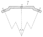
- FIG. 24 shows an embodiment in which each rigid member constituting the cross unit is greatly curved in the thickness direction to form an arc shape.
- FIG. 24 (a) shows a contracted state
- FIG. 24 (b) shows a stretched state.
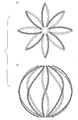
- the extendable arm forms a part of a spherical surface in the unfolded state of the extendable arm.
- the telescopic arms in the unfolded state form a spherical surface by curving each rigid member in the thickness direction to be a semicircular arc having a depression angle of 180 degrees.
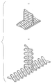
- FIG. 43 shows an example in which the telescopic arm forms a sphere.
- A) shows a plan view and
- B) shows a front view.
- Each rigid member has a shape that is largely curved in the thickness direction to form a semicircular arc of approximately 180 degrees.
- FIG. 44 shows an example in which the telescopic arm forms a cone.
- A is a top view
- (b) is a front view.
- Each rigid member has a curved shape in both the thickness direction and the width direction.
- each rigid member when forming a spiral shape using an extendable arm, each rigid member is curved in both the thickness direction and the width direction, and one rigid member constituting a pair has the other rigidity Make it longer than the member.
- 25 to 30 are illustrative views showing an example of use of the extendable arm.
- FIG. 25 shows an example in which the telescopic arm 60 is used for a desk lamp.
- (A) shows a state in which the extendable arm 60 is contracted, and (b) shows a state in which the extendable arm 60 is expanded.
- a lighting lamp 61 is attached to the tip of the telescopic arm 60.
- the telescopic arm 60 is installed, for example, on a desk. As shown in FIG. 22, in the state where the extendable arm 60 is extended, the extendable arm has a largely curved shape, so a large working space can be secured under the extendable arm 60.
- FIG. 26 shows an example in which the telescopic arm 62 is used for a clothes hanger. Since the telescopic arm 62 in the extended state has a curved shape, clothes or the like can be suspended at various heights by attaching a hanger or a hook 63 to the telescopic arm 62 in any place. The vertical heights of the plurality of attachment positions of the hangers and the hooks can be changed or the horizontal positions can be shifted if a plurality of telescopic arms of various shapes are appropriately combined and configured. .
- FIG. 27 shows an example in which the telescopic arm 64 is used for the beverage container stand on the handrail 65 of the seat.
- a container receiver 65 is attached to the tip of the telescopic arm 64.
- FIG. 27A a large space is secured in front of the seat in a state in which the telescopic arm 64 is contracted.
- FIG. 27 (b) when the extendable arm 64 is extended, the container receiver 65 is positioned in front of the seat occupant.
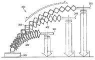
- FIG. 28 shows an example in which the telescopic arm 66 is used for an arched bridge. Further, FIG. 29 shows an example in which the telescopic arm 67 is used as a decoration rail of a Christmas tree.
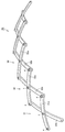
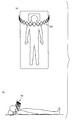
- FIG. 30 shows an example in which the telescopic arm 68 is used for a visual object holding device attached to a bed.
- the telescopic arm 68 In the extended state, the telescopic arm 68 has a shape that is greatly curved from the side of the bed to the upper side of the face of the person sleeping on the bed.
- This telescopic arm 68 is a visual object such as a book or an information display A person can read and watch the visual object easily by attaching a holding table that holds the object.
- each rigid member may be devised, or the arc shape, the spiral shape, or the wave may be appropriately combined by appropriately combining cross units composed of rigid members of different shapes.
- the shape, etc. can be designed freely.
- FIG. 31 shows an example of a partition, in which a plurality of telescopic arms are connected in the width direction intersecting the longitudinal direction to extend in the vertical and horizontal directions to have a large area.
- the illustrated partitions are curved in a wave shape to have a shape with enhanced design.
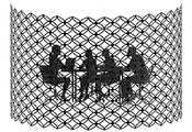
- FIG. 32 shows an example of a partition in the form of a cylindrical surface
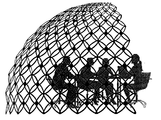
- FIG. 33 shows an example of a partition in the form of a spherical surface.
- partitions of any form can be formed by appropriately devising the shape of the rigid member.
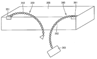
- FIG. 34 shows an example of a desk lamp using a telescopic arm according to an embodiment of the present invention.
- the electric stand 300 includes an extendable arm 302 according to an embodiment of the present invention, a base member 301 supporting a proximal end of the extendable arm 302 and incorporating a power control unit, and an illumination lamp 303 attached to the tip of the extendable arm 302. And an electric cord (not shown) extending from the base member 301 to the illumination lamp 302.
- connection points at both ends of each rigid member forming the cross unit are offset in the width direction of the rigid member, and the irradiation direction of the illumination lamp 303 is the telescopic arm 302. It is constant without being influenced by the expansion and contraction state of
- FIG. 34 shows the three states of the telescopic arm 302, that is, the contracted state, the intermediate state and the extended state.
- the illumination lamp 303 always emits light in a direction perpendicular to the table surface regardless of the position of the extension arm 302.
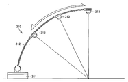
- FIG. 35 shows another example of a desk lamp using a telescopic arm according to another embodiment of the present invention.
- the electric stand 310 includes a telescopic arm 312, a base member 311 supporting a proximal end of the telescopic arm 312 and incorporating a power supply control unit, a lighting lamp 313 attached to the tip of the telescopic arm 312, and a lighting lamp from the base member 311 And an electrical cord (not shown) extending up to 313.
- the connection points at both ends of each rigid member forming the cross unit are offset in the thickness direction of the rigid member.
- the radius of curvature of the telescopic arm 312 is constant regardless of the change in the telescopic state. Therefore, the illumination lamp 313 emits light to the same position on the table without being influenced by the expansion and contraction state of the expansion and contraction arm 312.
- FIG. 35 shows an example of a desk lamp
- a laser irradiation apparatus can also be used with a similar configuration.
- FIG. 36 shows another example of the desk lamp.
- the illustrated electric stand 320 includes a base unit 321, a telescopic arm 322 according to the embodiment of the present invention supported at its base end by the base unit 321, and an illumination lamp 323 attached to the distal end of the telescopic arm 322.
- the connection point at each end of each rigid member constituting the extendable arm 322 is shifted in the width direction of the rigid member, so the irradiation direction of the illumination lamp 323 is constant without being influenced by the extendable state of the extendable arm 322 is there.
- the base unit 321 of the desk lamp shown in FIG. 36 connects the base member 321a placed directly on the table, the upper plate 321c for directly supporting the proximal end of the telescopic arm 322, and the base member 321a and the upper plate 321c. And an extendable arm 321 b.
- the telescopic arm 321b has a conventional structure, and crosses two linearly extending plate members in an X shape at the center to form a cross unit, and the cross units are vertically connected and straight in a vertical direction. Can be expanded and contracted.
- the positions of the telescopic arm 322 and the illumination lamp 323 can be translated in the vertical direction by extending and retracting the telescopic arm 321b.
- the plate member displaces the rigid member so as to allow change in the distance between the pair of rigid members. Support in an acceptable manner.
- the electrical cord connecting the base member and the illumination lamp is configured to pass within the thickness range of the telescopic arm.
- Various structures can be considered as a structure for realizing this configuration.
- the rigid member may be provided with recesses or holes for the passage of the electrical cord.
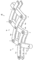
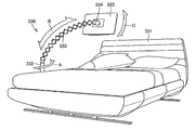
- FIG. 37 shows an example of a bed structure with telescopic arms using telescopic arms according to an embodiment of the present invention.
- the structure 330 shown in FIG. 37 includes a bed 331, a base member 332 fixed to the bed 331, and a telescopic arm 333 having a base end supported by the base member 332 and an article holding holding portion 334 at its tip.
- the article holding holder 334 holds a visual object 335 such as a touch panel display or a television display.
- the proximal end of the telescopic arm 333 is provided so as to be able to rotate around the longitudinal axis of the columnar base member 332 as shown by the arrow A.
- the article holding unit 334 preferably holds the display 335 rotatably as shown by an arrow C so that a person sleeping in the bed can change the angle of the visual object 335 appropriately.
- the telescopic arm 333 is telescopic as shown by arrow B.
- the telescopic arm 333 pivotally connects two rigid members at a central connection point to form an X-shaped cross unit, and a plurality of cross units are connected in one direction and rotated relative to each other. It is connected in a movable manner.
- Each rigid member is positioned such that the connection points at both ends thereof are offset from the longitudinal axis with respect to the longitudinal axis passing through the central connection point so that the expansion and contraction locus of the extendable arm draws a curved line. It has a curved shape.
- connection points at both ends of each rigid member are offset in the thickness direction of the rigid member. Therefore, the visual object 335 held by the article holding portion 334 can provide a visual surface always facing the face of the person sleeping in the bed without being influenced by the expansion and contraction state of the expansion and contraction arm 333.
- FIG. 38 shows another example of the bed structure with telescopic arms.
- a first telescopic arm 341 extends from one side of the bed and a second telescopic arm 342 extends from the other side of the bed.
- the tip of the first telescopic arm 341 and the tip of the second telescopic arm 342 are connected to a common article holding portion 343.
- the article holding unit 343 holds the visual object 344.
- the visual object 344 can be moved in a wide area from one side of the bed to the other.
- FIG. 39 shows two examples of the article holding device.
- One article holding device 350 holds the illumination lamp 353, and the other goods holding device 360 holds the touch panel display 363.
- One article holding device 350 includes a base member 351 fixed to furniture 355 such as a book shelf, and a telescopic arm 352 supported at its base end by the base member 351 and holding the illumination lamp 353 at its tip.
- the other article holding device 360 includes a base member 361 fixed to furniture 355 such as a book shelf, and a telescopic arm 362 having a base end supported by the base member 361 and holding a touch panel display 363 at its tip.
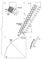
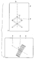
- FIG. 40 shows an example in which a television display holding apparatus 400 is configured using a telescopic arm 401 including 13 cross links. Specific dimensions are shown in the drawings as an example.
- a television display 402 is attached to the tip of the extendable arm 401.
- the connection points at both ends of each rigid member are offset in the thickness direction of the rigid member. Therefore, the radius of curvature of the telescopic arm 401 is constant regardless of the change in the telescopic state.
- the length of the telescopic arm 401 in the most contracted state is 156 mm.
- (B) and (c) of FIG. 40 show a state in which the extendable arm 401 is extended until the television display 402 reaches the highest position (90 degrees angle).
- the radius of curvature of the telescopic arm 401 is 704 mm, and the distance between adjacent cross links is 79.2 mm. Further, an angle between a pair of rigid members constituting one cross link is 110.0 °.
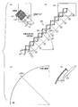
- FIG. 41 shows a television display holder 500 supporting a television display 502 by means of telescoping arms 501 comprising 10 cross links.
- the extendable arm 501 connection points at both ends of each rigid member are offset in the thickness direction of the rigid member. Therefore, the radius of curvature of the telescopic arm 501 is constant regardless of the change in the telescopic state.
- the length of the telescopic arm 501 in the most contracted state is 120 mm.
- (B) and (c) of FIG. 41 show a state in which the extendable arm 501 is extended until the television display 502 reaches the highest position (90 degrees angle).
- the radius of curvature of the extendable arm 501 is 704 mm, and the distance between adjacent cross links is 105.7 mm. Further, an angle formed by a pair of rigid members constituting one cross link is 80 °.
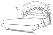
- 45 to 46 show an example in which the article holding device is applied to a visual object holding device. Specifically, an example in which the visual object holding device is attached to the bed is shown. As shown in FIG. 45 (a), if the track of the telescopic movement of the telescopic arm is at an angle of approximately 60 degrees with respect to the horizontal plane, the person lying on the bed can easily see the visual object 700.
- each rigid member constituting the telescopic arm is curved in the thickness direction. If a telescopic arm is configured using a rigid member curved in the thickness direction, as shown in FIG. 45 (b), the visual object is the person sleeping on the bed without being affected by the telescopic state of the telescopic arm. It can provide a visual plane orthogonal to the face.
- a person sleeping on a bed turns sideways to look at the visual object or to look at the visual object in a supine state.
- the connecting structure of the telescopic arm and the article holding holding member is a telescopic arm so that the person on the bed can easily see the visual object in both the lateral state and the supine state.
- the angle of the holding member for holding the article with respect to the longitudinal axis is configured to change in accordance with the expansion and contraction operation of the expansion and contraction arm.
- the visual surface of the visual object 700 is at an angular position where the sideways person can easily view, and the telescopic arm extends.
- the central transverse line 702 of the visual surface of the visual object 700 is substantially parallel to the longitudinal axis 701 of the telescopic arm. It becomes a relationship and easy to see.
- FIG. 46 shows the connection between the telescopic arm and the visual object.
- A shows a state in which the extendable arm is contracted
- (b) shows a state in which the extendable arm is expanded.
- one rigid member 703 located at the tip of the telescopic arm is angularly fixedly connected to the visual object 704.
- the rigid member 703 changes the angle with respect to the longitudinal axis 705 of the extendable arm from ⁇ 1 to ⁇ 2 according to the expansion and contraction operation of the extendable arm, the visual object 704 fixedly connected to the rigid member 703 is fixed. Also change the angle with respect to the longitudinal axis 705 of the telescopic arm.
- the angle of the visual object is also changed using the angle change of the rigid member located at the tip, but as another example, according to the change of the extension length of the extendable arm
- the angle of the visual object may be changed by changing the angle of the visual object, or using a gear linked to the expansion and contraction operation of the telescopic arm.
- FIG. 42 schematically shows a connecting portion at both ends of the extendable arm 600.
- the ends of the pair of rigid members located at the far end of the extension arm 600 in the lengthwise direction It supports slidably along.
- the angle of at least one cross link may be fixed or the position of the connection point of the adjacent rigid members may be fixed.
- expansion-contraction arm Although it does not specifically limit regarding the material which forms an expansion-contraction arm, For example, metal, a plastics, wood, ceramics, hard rubber, or those composites etc. can be utilized.
- (A) object decoration arch shape, circular shape, spherical shape, cylindrical shape, wave shape, S shape, spiral shape, spiral shape, oval shape, conical shape etc.
- Animal houses (g) Umbrella, cone (h) Robot arm (i) Hanger (j) Open car roof (k) Ornamental illumination (l) Tent (m) Fan cover (n Shade of lighting fixtures
- the present invention can be advantageously used as a telescopic arm that can form a curved shape in a balanced and stable manner.
Landscapes
- Engineering & Computer Science (AREA)
- General Engineering & Computer Science (AREA)
- Mechanical Engineering (AREA)
- Robotics (AREA)
- Manipulator (AREA)
- Non-Portable Lighting Devices Or Systems Thereof (AREA)
- Arrangement Of Elements, Cooling, Sealing, Or The Like Of Lighting Devices (AREA)
- Pivots And Pivotal Connections (AREA)
Priority Applications (4)
| Application Number | Priority Date | Filing Date | Title |
|---|---|---|---|
| CN201380042763.6A CN104540649B (zh) | 2013-01-28 | 2013-12-05 | 伸缩臂及使用伸缩臂的构造物 |
| KR1020157004218A KR102099628B1 (ko) | 2013-01-28 | 2013-12-05 | 신축 아암 및 신축 아암을 이용한 구조물 |
| EP13872717.7A EP2949434B1 (en) | 2013-01-28 | 2013-12-05 | Telescopic arm and structure using telescopic arm |
| US14/421,712 US9316350B2 (en) | 2013-01-28 | 2013-12-05 | Extendable arm and structure using the same |
Applications Claiming Priority (4)
| Application Number | Priority Date | Filing Date | Title |
|---|---|---|---|
| JP2013013269 | 2013-01-28 | ||
| JP2013-013269 | 2013-01-28 | ||
| JP2013239210A JP5837023B2 (ja) | 2013-01-28 | 2013-11-19 | 伸縮アームおよび伸縮アームを用いた構造物 |
| JP2013-239210 | 2013-11-19 |
Publications (1)
| Publication Number | Publication Date |
|---|---|
| WO2014115428A1 true WO2014115428A1 (ja) | 2014-07-31 |
Family
ID=51227231
Family Applications (1)
| Application Number | Title | Priority Date | Filing Date |
|---|---|---|---|
| PCT/JP2013/082655 Ceased WO2014115428A1 (ja) | 2013-01-28 | 2013-12-05 | 伸縮アームおよび伸縮アームを用いた構造物 |
Country Status (7)
| Country | Link |
|---|---|
| US (1) | US9316350B2 (enExample) |
| EP (1) | EP2949434B1 (enExample) |
| JP (1) | JP5837023B2 (enExample) |
| KR (1) | KR102099628B1 (enExample) |
| CN (1) | CN104540649B (enExample) |
| TW (1) | TWI585331B (enExample) |
| WO (1) | WO2014115428A1 (enExample) |
Cited By (3)
| Publication number | Priority date | Publication date | Assignee | Title |
|---|---|---|---|---|
| CN104369180A (zh) * | 2014-10-20 | 2015-02-25 | 佛山市禾才科技服务有限公司 | 一种四边形复合机械臂 |
| CN104608147A (zh) * | 2014-12-09 | 2015-05-13 | 佛山市禾才科技服务有限公司 | 一种弯曲伸缩的机械臂 |
| CN104712174A (zh) * | 2015-01-14 | 2015-06-17 | 佛山市禾才科技服务有限公司 | 一种可伸缩折叠的立体结构 |
Families Citing this family (36)
| Publication number | Priority date | Publication date | Assignee | Title |
|---|---|---|---|---|
| JP5996713B1 (ja) * | 2015-04-30 | 2016-09-21 | 株式会社不二宮製作所 | 伸縮アームを用いた面積可変枠体及び体積可変立体構造物 |
| CN105380458A (zh) * | 2015-11-25 | 2016-03-09 | 宁波市新光货架有限公司 | 一种改进型壁挂轻型货架 |
| CN105380457A (zh) * | 2015-11-25 | 2016-03-09 | 宁波市新光货架有限公司 | 一种壁挂轻型货架 |
| US10228100B2 (en) * | 2015-12-01 | 2019-03-12 | Philips Lighting Holding B.V. | Lighting device and lighting system |
| CN105526246A (zh) * | 2016-01-22 | 2016-04-27 | 佛山市禾才科技服务有限公司 | 一种可收缩的剪式付组半圆面和弧面 |
| CN107237549A (zh) * | 2016-03-28 | 2017-10-10 | 佛山市禾才科技服务有限公司 | 一种可变尺寸的四边形安全护栏 |
| CN107237548A (zh) * | 2016-03-28 | 2017-10-10 | 佛山市禾才科技服务有限公司 | 一种可变尺寸的三边形安全护栏 |
| KR101812134B1 (ko) * | 2016-04-11 | 2017-12-27 | 아이투엠 주식회사 | 외형이 변형되는 주름형상의 갓을 갖는 조명기구 |
| JP6456881B2 (ja) * | 2016-07-19 | 2019-01-23 | 株式会社不二宮製作所 | 伸縮アームを用いた形状可変立体構造物 |
| JP6391124B2 (ja) | 2016-08-08 | 2018-09-19 | 株式会社不二宮製作所 | 伸縮アームを用いた形状可変立体構造物 |
| JP6391125B2 (ja) | 2016-08-22 | 2018-09-19 | 株式会社不二宮製作所 | 伸縮アームを用いた形状可変枠体 |
| JP6341578B2 (ja) | 2016-12-06 | 2018-06-13 | 株式会社不二宮製作所 | 形状可変枠体および形状可変立体構造物 |
| CN108237523B (zh) * | 2016-12-23 | 2024-11-19 | 佛山顺德光启尖端装备有限公司 | 机器人伸脖子装置及具有其的机器人 |
| US10093226B1 (en) * | 2017-08-09 | 2018-10-09 | Ford Global Technologies, Llc | Deployable vehicle light assembly |
| CN107504446A (zh) * | 2017-10-19 | 2017-12-22 | 湖州明日照明科技有限公司 | 一种多功能折叠式照明灯具 |
| CN108161898A (zh) * | 2017-12-25 | 2018-06-15 | 佛山市禾才科技服务有限公司 | 一种类桁架式机械臂 |
| JP6943440B2 (ja) | 2018-04-17 | 2021-09-29 | 株式会社不二宮製作所 | 伸縮アーム構造体 |
| CN108730712A (zh) * | 2018-08-23 | 2018-11-02 | 吉林合纵信息技术有限公司 | 一种平板电脑支架 |
| CN109036074A (zh) * | 2018-08-30 | 2018-12-18 | 溧阳市科创电子电器有限公司 | 一种便于制作伸缩拳 |
| US12031663B1 (en) * | 2019-02-25 | 2024-07-09 | Russ Bassett Corporation | Array with lateral movement |
| JP6860224B2 (ja) | 2019-03-04 | 2021-04-14 | 株式会社不二宮製作所 | 伸縮アーム |
| CN109882723B (zh) * | 2019-04-02 | 2024-02-23 | 安徽理工大学 | 一种嵌入式壁挂安装装置及具有其的壁挂式设备 |
| US11491645B2 (en) * | 2019-06-07 | 2022-11-08 | Massachusetts Institute Of Technology | Scissor linkage design and method of operation |
| JP2020199568A (ja) | 2019-06-07 | 2020-12-17 | 株式会社不二宮製作所 | 伸縮アーム、形状可変枠体および形状可変立体構造物 |
| CN110151433B (zh) * | 2019-07-03 | 2020-10-30 | 河南省中医院(河南中医药大学第二附属医院) | 一种icu病床专用床头卡 |
| CN110939846B (zh) * | 2019-12-16 | 2021-03-23 | 成都市舒是智能家居有限公司 | 一种支架组件的控制方法 |
| US11131112B2 (en) * | 2020-02-19 | 2021-09-28 | Zenithen USA, LLC | Expandable canopy tent frame |
| US11690951B1 (en) * | 2020-04-03 | 2023-07-04 | The Cleveland Clinic Foundation | IV tubing carriage system |
| JP6937527B1 (ja) * | 2020-05-15 | 2021-09-22 | 株式会社不二宮製作所 | 屈曲部材を備える視覚的興味刺激構造体 |
| US20220330519A1 (en) * | 2021-04-20 | 2022-10-20 | John Chitkowski | Elevatable pet bed platform assembly |
| CN113230078B (zh) * | 2021-06-10 | 2022-06-28 | 上海长征医院 | 一种颈椎手术操作中病患头部固定装置 |
| CN113466763B (zh) * | 2021-07-19 | 2023-07-25 | 广东电网有限责任公司 | 超导电缆变径弯曲测试装置及其测试方法 |
| CN215982185U (zh) * | 2021-09-16 | 2022-03-08 | 深圳北极之光科技有限公司 | 一种可伸缩的led植物灯 |
| US12011108B1 (en) | 2021-11-17 | 2024-06-18 | Marcus-Alan Asher Brown | Adjustable hanger |
| JP7194477B1 (ja) * | 2022-01-31 | 2022-12-22 | 株式会社不二宮製作所 | 複数の連結部を備える連結構造体および形状可変部材 |
| JP1745941S (enExample) * | 2022-11-30 | 2023-06-09 |
Citations (8)
| Publication number | Priority date | Publication date | Assignee | Title |
|---|---|---|---|---|
| JPS5033126U (enExample) * | 1973-07-21 | 1975-04-10 | ||
| JPS613409U (ja) * | 1984-06-13 | 1986-01-10 | 日立造船株式会社 | 伸縮ア−ム |
| JPS62166985A (ja) * | 1986-01-20 | 1987-07-23 | 日本電信電話株式会社 | マニピユレ−タ |
| JPH01159036U (enExample) | 1988-04-25 | 1989-11-02 | ||
| JPH11151124A (ja) * | 1997-11-25 | 1999-06-08 | Mimoto:Kk | 患者用のテレビ支持金具 |
| JP2006052603A (ja) | 2004-08-16 | 2006-02-23 | Takanori Hatanaka | 伸縮構造体ならびに折り畳み式梯子、折り畳み式支持台、折り畳み式器具および折り畳み式パイプ |
| US20090158674A1 (en) * | 2007-12-21 | 2009-06-25 | Schlumberger Technology Corporation | System and methods for actuating reversibly expandable structures |
| JP3174754U (ja) * | 2012-01-24 | 2012-04-05 | 碧芬 林 | 自動的に伸縮可能な照明構造 |
Family Cites Families (20)
| Publication number | Priority date | Publication date | Assignee | Title |
|---|---|---|---|---|
| DE8303281U1 (de) * | 1983-09-15 | Herzog, Thomas, Prof. Dr., 8000 München | Scherengitter zur Erzeugung von Verstellbewegungen | |
| US2013882A (en) * | 1933-07-14 | 1935-09-10 | Robert B Francis | Bed attachment |
| DE807286C (de) * | 1948-11-16 | 1951-06-28 | Cosack O H G Geb | Scherenarm |
| US3168791A (en) * | 1961-08-28 | 1965-02-09 | Donald W Nutting | Book holder |
| JPS5427272Y2 (enExample) * | 1975-06-24 | 1979-09-05 | ||
| JPS54117081U (enExample) | 1978-02-03 | 1979-08-16 | ||
| JPS57107788A (en) * | 1980-12-26 | 1982-07-05 | Tokyo Shibaura Electric Co | Extensible arm |
| JPH0234729Y2 (enExample) | 1987-07-28 | 1990-09-19 | ||
| JPH01159036A (ja) | 1987-12-15 | 1989-06-22 | Kao Corp | 乳化組成物の製造法 |
| JP3274754B2 (ja) * | 1993-09-30 | 2002-04-15 | 日本エステル株式会社 | 目ずれ防止効果を有する太細糸 |
| US6061923A (en) * | 1998-12-03 | 2000-05-16 | Case; Agnes G. | Wall-mounted extendable hair dryer holder |
| DE19923257A1 (de) * | 1999-05-20 | 2000-11-23 | Sabine Wald | Variables Scherengittergestell |
| EP1223378A1 (de) * | 2001-01-15 | 2002-07-17 | Oliver Michl | Scherengitter |
| USD555202S1 (en) * | 2005-03-10 | 2007-11-13 | Cri2000, Lp | Expandable document holder |
| US8733453B2 (en) | 2007-12-21 | 2014-05-27 | Schlumberger Technology Corporation | Expandable structure for deployment in a well |
| US7896088B2 (en) | 2007-12-21 | 2011-03-01 | Schlumberger Technology Corporation | Wellsite systems utilizing deployable structure |
| CN201131519Y (zh) * | 2007-12-27 | 2008-10-15 | 杭州银格旅游用品有限公司 | 折叠休闲床 |
| CN101744440A (zh) * | 2008-12-06 | 2010-06-23 | 刘运果 | 一种基于异形伞伞骨的新型x形伸缩节设计 |
| DE102009010933B4 (de) * | 2009-02-27 | 2016-05-04 | Christoph Niedeggen | Scherenarm zur Positionierung eines Leuchtenkopfes |
| AU2011275324A1 (en) | 2010-07-08 | 2013-01-24 | Nadav Gavish | A sheltering device |
-
2013
- 2013-11-19 JP JP2013239210A patent/JP5837023B2/ja active Active
- 2013-12-05 WO PCT/JP2013/082655 patent/WO2014115428A1/ja not_active Ceased
- 2013-12-05 KR KR1020157004218A patent/KR102099628B1/ko active Active
- 2013-12-05 US US14/421,712 patent/US9316350B2/en active Active
- 2013-12-05 CN CN201380042763.6A patent/CN104540649B/zh active Active
- 2013-12-05 EP EP13872717.7A patent/EP2949434B1/en active Active
-
2014
- 2014-01-03 TW TW103100157A patent/TWI585331B/zh active
Patent Citations (8)
| Publication number | Priority date | Publication date | Assignee | Title |
|---|---|---|---|---|
| JPS5033126U (enExample) * | 1973-07-21 | 1975-04-10 | ||
| JPS613409U (ja) * | 1984-06-13 | 1986-01-10 | 日立造船株式会社 | 伸縮ア−ム |
| JPS62166985A (ja) * | 1986-01-20 | 1987-07-23 | 日本電信電話株式会社 | マニピユレ−タ |
| JPH01159036U (enExample) | 1988-04-25 | 1989-11-02 | ||
| JPH11151124A (ja) * | 1997-11-25 | 1999-06-08 | Mimoto:Kk | 患者用のテレビ支持金具 |
| JP2006052603A (ja) | 2004-08-16 | 2006-02-23 | Takanori Hatanaka | 伸縮構造体ならびに折り畳み式梯子、折り畳み式支持台、折り畳み式器具および折り畳み式パイプ |
| US20090158674A1 (en) * | 2007-12-21 | 2009-06-25 | Schlumberger Technology Corporation | System and methods for actuating reversibly expandable structures |
| JP3174754U (ja) * | 2012-01-24 | 2012-04-05 | 碧芬 林 | 自動的に伸縮可能な照明構造 |
Non-Patent Citations (1)
| Title |
|---|
| See also references of EP2949434A4 |
Cited By (3)
| Publication number | Priority date | Publication date | Assignee | Title |
|---|---|---|---|---|
| CN104369180A (zh) * | 2014-10-20 | 2015-02-25 | 佛山市禾才科技服务有限公司 | 一种四边形复合机械臂 |
| CN104608147A (zh) * | 2014-12-09 | 2015-05-13 | 佛山市禾才科技服务有限公司 | 一种弯曲伸缩的机械臂 |
| CN104712174A (zh) * | 2015-01-14 | 2015-06-17 | 佛山市禾才科技服务有限公司 | 一种可伸缩折叠的立体结构 |
Also Published As
| Publication number | Publication date |
|---|---|
| TW201437534A (zh) | 2014-10-01 |
| TWI585331B (zh) | 2017-06-01 |
| KR20150111901A (ko) | 2015-10-06 |
| US9316350B2 (en) | 2016-04-19 |
| CN104540649B (zh) | 2016-10-05 |
| EP2949434A4 (en) | 2016-11-02 |
| EP2949434A1 (en) | 2015-12-02 |
| JP2014159070A (ja) | 2014-09-04 |
| CN104540649A (zh) | 2015-04-22 |
| EP2949434B1 (en) | 2019-02-20 |
| KR102099628B1 (ko) | 2020-04-10 |
| JP5837023B2 (ja) | 2015-12-24 |
| US20150300560A1 (en) | 2015-10-22 |
Similar Documents
| Publication | Publication Date | Title |
|---|---|---|
| JP5837023B2 (ja) | 伸縮アームおよび伸縮アームを用いた構造物 | |
| JP6341578B2 (ja) | 形状可変枠体および形状可変立体構造物 | |
| JP2014159070A5 (enExample) | ||
| US8764234B1 (en) | Decorative sphere | |
| JP2016211617A (ja) | 伸縮アームを用いた面積可変枠体及び体積可変立体構造物 | |
| RU2009122367A (ru) | Ударный музыкальный инструмент | |
| JP6630075B2 (ja) | フレーム式ブース状家具 | |
| CN201831402U (zh) | 婴儿床 | |
| ITAN20100108A1 (it) | Tavolo rotondo allungabile. | |
| CN201958316U (zh) | 双人折叠床 | |
| JP5945458B2 (ja) | 複合ロクロの連動構造 | |
| KR20200145630A (ko) | 식당의자용 승하강 장치 | |
| CN110313755A (zh) | 一种可伸缩博物馆展柜 | |
| RU2441124C1 (ru) | Стремянка | |
| JP3197414U (ja) | 介助装置及び介助補助体 | |
| JP4296229B1 (ja) | 自立型扇状装飾部材 | |
| CN208243322U (zh) | 可旋转伸缩衣物展架 | |
| CN203563952U (zh) | 多功能折叠床 | |
| CN104273974A (zh) | 带有简易蚊帐支撑架的床 | |
| CN222623280U (zh) | 一种外科换药支架 | |
| CN221724151U (zh) | 一种铁丝鸟笼式落地灯 | |
| JP2017153864A (ja) | 昇降テーブル | |
| CN211796899U (zh) | 一种多功能出诊箱 | |
| JPH11299611A (ja) | 簡易組み立てカーテン | |
| ES2293803B1 (es) | Salvamanteles. |
Legal Events
| Date | Code | Title | Description |
|---|---|---|---|
| 121 | Ep: the epo has been informed by wipo that ep was designated in this application |
Ref document number: 13872717 Country of ref document: EP Kind code of ref document: A1 |
|
| WWE | Wipo information: entry into national phase |
Ref document number: 14421712 Country of ref document: US Ref document number: 2013872717 Country of ref document: EP |
|
| ENP | Entry into the national phase |
Ref document number: 20157004218 Country of ref document: KR Kind code of ref document: A |
|
| NENP | Non-entry into the national phase |
Ref country code: DE |