EP2949434B1 - Telescopic arm and structure using telescopic arm - Google Patents
Telescopic arm and structure using telescopic arm Download PDFInfo
- Publication number
- EP2949434B1 EP2949434B1 EP13872717.7A EP13872717A EP2949434B1 EP 2949434 B1 EP2949434 B1 EP 2949434B1 EP 13872717 A EP13872717 A EP 13872717A EP 2949434 B1 EP2949434 B1 EP 2949434B1
- Authority
- EP
- European Patent Office
- Prior art keywords
- extendable arm
- rigid member
- extendable
- shape
- curved
- Prior art date
- Legal status (The legal status is an assumption and is not a legal conclusion. Google has not performed a legal analysis and makes no representation as to the accuracy of the status listed.)
- Active
Links
Images


Classifications
-
- F—MECHANICAL ENGINEERING; LIGHTING; HEATING; WEAPONS; BLASTING
- F16—ENGINEERING ELEMENTS AND UNITS; GENERAL MEASURES FOR PRODUCING AND MAINTAINING EFFECTIVE FUNCTIONING OF MACHINES OR INSTALLATIONS; THERMAL INSULATION IN GENERAL
- F16M—FRAMES, CASINGS OR BEDS OF ENGINES, MACHINES OR APPARATUS, NOT SPECIFIC TO ENGINES, MACHINES OR APPARATUS PROVIDED FOR ELSEWHERE; STANDS; SUPPORTS
- F16M13/00—Other supports for positioning apparatus or articles; Means for steadying hand-held apparatus or articles
- F16M13/02—Other supports for positioning apparatus or articles; Means for steadying hand-held apparatus or articles for supporting on, or attaching to, an object, e.g. tree, gate, window-frame, cycle
- F16M13/022—Other supports for positioning apparatus or articles; Means for steadying hand-held apparatus or articles for supporting on, or attaching to, an object, e.g. tree, gate, window-frame, cycle repositionable
-
- A—HUMAN NECESSITIES
- A47—FURNITURE; DOMESTIC ARTICLES OR APPLIANCES; COFFEE MILLS; SPICE MILLS; SUCTION CLEANERS IN GENERAL
- A47B—TABLES; DESKS; OFFICE FURNITURE; CABINETS; DRAWERS; GENERAL DETAILS OF FURNITURE
- A47B23/00—Bed-tables; Trays; Reading-racks; Book-rests, i.e. items used in combination with something else
- A47B23/007—Overhead reading-racks or book-rests
-
- A—HUMAN NECESSITIES
- A47—FURNITURE; DOMESTIC ARTICLES OR APPLIANCES; COFFEE MILLS; SPICE MILLS; SUCTION CLEANERS IN GENERAL
- A47B—TABLES; DESKS; OFFICE FURNITURE; CABINETS; DRAWERS; GENERAL DETAILS OF FURNITURE
- A47B23/00—Bed-tables; Trays; Reading-racks; Book-rests, i.e. items used in combination with something else
- A47B23/02—Bed-tables; Trays; Reading-racks; Book-rests, i.e. items used in combination with something else releasably mounted on the bedstead or another item of furniture
- A47B23/025—Bed-tables; Trays; Reading-racks; Book-rests, i.e. items used in combination with something else releasably mounted on the bedstead or another item of furniture mounted on the bedstead
-
- A—HUMAN NECESSITIES
- A47—FURNITURE; DOMESTIC ARTICLES OR APPLIANCES; COFFEE MILLS; SPICE MILLS; SUCTION CLEANERS IN GENERAL
- A47C—CHAIRS; SOFAS; BEDS
- A47C21/00—Attachments for beds, e.g. sheet holders or bed-cover holders; Ventilating, cooling or heating means in connection with bedsteads or mattresses
- A47C21/003—Lighting, radio, telephone or the like connected to the bedstead
-
- A—HUMAN NECESSITIES
- A63—SPORTS; GAMES; AMUSEMENTS
- A63H—TOYS, e.g. TOPS, DOLLS, HOOPS OR BUILDING BLOCKS
- A63H33/00—Other toys
-
- B—PERFORMING OPERATIONS; TRANSPORTING
- B25—HAND TOOLS; PORTABLE POWER-DRIVEN TOOLS; MANIPULATORS
- B25J—MANIPULATORS; CHAMBERS PROVIDED WITH MANIPULATION DEVICES
- B25J18/00—Arms
- B25J18/02—Arms extensible
-
- F—MECHANICAL ENGINEERING; LIGHTING; HEATING; WEAPONS; BLASTING
- F16—ENGINEERING ELEMENTS AND UNITS; GENERAL MEASURES FOR PRODUCING AND MAINTAINING EFFECTIVE FUNCTIONING OF MACHINES OR INSTALLATIONS; THERMAL INSULATION IN GENERAL
- F16M—FRAMES, CASINGS OR BEDS OF ENGINES, MACHINES OR APPARATUS, NOT SPECIFIC TO ENGINES, MACHINES OR APPARATUS PROVIDED FOR ELSEWHERE; STANDS; SUPPORTS
- F16M11/00—Stands or trestles as supports for apparatus or articles placed thereon ; Stands for scientific apparatus such as gravitational force meters
- F16M11/02—Heads
- F16M11/04—Means for attachment of apparatus; Means allowing adjustment of the apparatus relatively to the stand
- F16M11/06—Means for attachment of apparatus; Means allowing adjustment of the apparatus relatively to the stand allowing pivoting
- F16M11/10—Means for attachment of apparatus; Means allowing adjustment of the apparatus relatively to the stand allowing pivoting around a horizontal axis
-
- F—MECHANICAL ENGINEERING; LIGHTING; HEATING; WEAPONS; BLASTING
- F16—ENGINEERING ELEMENTS AND UNITS; GENERAL MEASURES FOR PRODUCING AND MAINTAINING EFFECTIVE FUNCTIONING OF MACHINES OR INSTALLATIONS; THERMAL INSULATION IN GENERAL
- F16M—FRAMES, CASINGS OR BEDS OF ENGINES, MACHINES OR APPARATUS, NOT SPECIFIC TO ENGINES, MACHINES OR APPARATUS PROVIDED FOR ELSEWHERE; STANDS; SUPPORTS
- F16M11/00—Stands or trestles as supports for apparatus or articles placed thereon ; Stands for scientific apparatus such as gravitational force meters
- F16M11/20—Undercarriages with or without wheels
- F16M11/2007—Undercarriages with or without wheels comprising means allowing pivoting adjustment
- F16M11/2014—Undercarriages with or without wheels comprising means allowing pivoting adjustment around a vertical axis
-
- F—MECHANICAL ENGINEERING; LIGHTING; HEATING; WEAPONS; BLASTING
- F16—ENGINEERING ELEMENTS AND UNITS; GENERAL MEASURES FOR PRODUCING AND MAINTAINING EFFECTIVE FUNCTIONING OF MACHINES OR INSTALLATIONS; THERMAL INSULATION IN GENERAL
- F16M—FRAMES, CASINGS OR BEDS OF ENGINES, MACHINES OR APPARATUS, NOT SPECIFIC TO ENGINES, MACHINES OR APPARATUS PROVIDED FOR ELSEWHERE; STANDS; SUPPORTS
- F16M11/00—Stands or trestles as supports for apparatus or articles placed thereon ; Stands for scientific apparatus such as gravitational force meters
- F16M11/20—Undercarriages with or without wheels
- F16M11/2092—Undercarriages with or without wheels comprising means allowing depth adjustment, i.e. forward-backward translation of the head relatively to the undercarriage
-
- F—MECHANICAL ENGINEERING; LIGHTING; HEATING; WEAPONS; BLASTING
- F16—ENGINEERING ELEMENTS AND UNITS; GENERAL MEASURES FOR PRODUCING AND MAINTAINING EFFECTIVE FUNCTIONING OF MACHINES OR INSTALLATIONS; THERMAL INSULATION IN GENERAL
- F16M—FRAMES, CASINGS OR BEDS OF ENGINES, MACHINES OR APPARATUS, NOT SPECIFIC TO ENGINES, MACHINES OR APPARATUS PROVIDED FOR ELSEWHERE; STANDS; SUPPORTS
- F16M11/00—Stands or trestles as supports for apparatus or articles placed thereon ; Stands for scientific apparatus such as gravitational force meters
- F16M11/20—Undercarriages with or without wheels
- F16M11/24—Undercarriages with or without wheels changeable in height or length of legs, also for transport only, e.g. by means of tubes screwed into each other
- F16M11/38—Undercarriages with or without wheels changeable in height or length of legs, also for transport only, e.g. by means of tubes screwed into each other by folding, e.g. pivoting or scissors tong mechanisms
-
- F—MECHANICAL ENGINEERING; LIGHTING; HEATING; WEAPONS; BLASTING
- F16—ENGINEERING ELEMENTS AND UNITS; GENERAL MEASURES FOR PRODUCING AND MAINTAINING EFFECTIVE FUNCTIONING OF MACHINES OR INSTALLATIONS; THERMAL INSULATION IN GENERAL
- F16M—FRAMES, CASINGS OR BEDS OF ENGINES, MACHINES OR APPARATUS, NOT SPECIFIC TO ENGINES, MACHINES OR APPARATUS PROVIDED FOR ELSEWHERE; STANDS; SUPPORTS
- F16M13/00—Other supports for positioning apparatus or articles; Means for steadying hand-held apparatus or articles
- F16M13/02—Other supports for positioning apparatus or articles; Means for steadying hand-held apparatus or articles for supporting on, or attaching to, an object, e.g. tree, gate, window-frame, cycle
-
- F—MECHANICAL ENGINEERING; LIGHTING; HEATING; WEAPONS; BLASTING
- F21—LIGHTING
- F21V—FUNCTIONAL FEATURES OR DETAILS OF LIGHTING DEVICES OR SYSTEMS THEREOF; STRUCTURAL COMBINATIONS OF LIGHTING DEVICES WITH OTHER ARTICLES, NOT OTHERWISE PROVIDED FOR
- F21V21/00—Supporting, suspending, or attaching arrangements for lighting devices; Hand grips
- F21V21/14—Adjustable mountings
- F21V21/24—Lazy-tongs
-
- F—MECHANICAL ENGINEERING; LIGHTING; HEATING; WEAPONS; BLASTING
- F21—LIGHTING
- F21V—FUNCTIONAL FEATURES OR DETAILS OF LIGHTING DEVICES OR SYSTEMS THEREOF; STRUCTURAL COMBINATIONS OF LIGHTING DEVICES WITH OTHER ARTICLES, NOT OTHERWISE PROVIDED FOR
- F21V21/00—Supporting, suspending, or attaching arrangements for lighting devices; Hand grips
- F21V21/14—Adjustable mountings
- F21V21/26—Pivoted arms
-
- F—MECHANICAL ENGINEERING; LIGHTING; HEATING; WEAPONS; BLASTING
- F16—ENGINEERING ELEMENTS AND UNITS; GENERAL MEASURES FOR PRODUCING AND MAINTAINING EFFECTIVE FUNCTIONING OF MACHINES OR INSTALLATIONS; THERMAL INSULATION IN GENERAL
- F16M—FRAMES, CASINGS OR BEDS OF ENGINES, MACHINES OR APPARATUS, NOT SPECIFIC TO ENGINES, MACHINES OR APPARATUS PROVIDED FOR ELSEWHERE; STANDS; SUPPORTS
- F16M2200/00—Details of stands or supports
- F16M2200/06—Arms
- F16M2200/061—Scissors arms
-
- F—MECHANICAL ENGINEERING; LIGHTING; HEATING; WEAPONS; BLASTING
- F21—LIGHTING
- F21S—NON-PORTABLE LIGHTING DEVICES; SYSTEMS THEREOF; VEHICLE LIGHTING DEVICES SPECIALLY ADAPTED FOR VEHICLE EXTERIORS
- F21S6/00—Lighting devices intended to be free-standing
-
- F—MECHANICAL ENGINEERING; LIGHTING; HEATING; WEAPONS; BLASTING
- F21—LIGHTING
- F21W—INDEXING SCHEME ASSOCIATED WITH SUBCLASSES F21K, F21L, F21S and F21V, RELATING TO USES OR APPLICATIONS OF LIGHTING DEVICES OR SYSTEMS
- F21W2121/00—Use or application of lighting devices or systems for decorative purposes, not provided for in codes F21W2102/00 – F21W2107/00
- F21W2121/04—Use or application of lighting devices or systems for decorative purposes, not provided for in codes F21W2102/00 – F21W2107/00 for Christmas trees
Definitions
- the present invention relates to extendable arms that can be extended and contracted, and more particularly to extendable arms in which a plurality of cross units each having an X-shape are arranged in one direction and are pivotally coupled to each other.
- Extendable arms are widely used in various kinds of industrial equipment, devices related to daily life, medical-related devices, etc., such as arms of industrial robots, stands of lighting devices, arms supporting a stand on which an article is placed.
- a typical extendable arm is formed by a plurality of cross units arranged in one direction and pivotally coupled to each other.
- Each of the cross units is formed by two linear plate members crossed over each other at their centers so as to form an X-shape and pivotally coupled together at the intersection via a shaft.
- the extendable arm having such a structure can be extended and contracted in a linear direction.
- the extendable arm may be extended and contracted in a curved direction.
- Such extendable arms that are extended and contracted in a curved direction are disclosed in, e.g., Japanese Unexamined Utility Model Application Publication No. H01-159036 (PTL 1) and Japanese Unexamined Patent Application Publication No. 2006-52603 (PTL 2).
- the extendable arm disclosed in Japanese Unexamined Utility Model Application Publication No. H01-159036 is used in a front roll-up type movable tent that is deployed so that canvas forms a curve in an intermediate part of the tent.
- the canvas is attached to extend between a base bar and a front bar
- the front bar is rotatably disposed between the tip ends of extendable arms
- a motor that rotates the front bar in the forward and reverse directions is coupled to the front bar.
- Each of the extendable arms is formed by a plurality of cross units arranged in one direction and pivotally coupled to each other, and each of the cross units is formed by two linear plate members that are crossed over each other to form an X-shape.
- the canvas When in a deployed state, the canvas has a curved region in an intermediate part thereof.
- Each of those cross units which are located in the curved region is provided so that its crossing shaft coupling the two plate members is provided at a position shifted from the centers of the plate members, in order to allow the cross units to be located along such a deployment path of the canvas.
- the length from the crossing shaft to the outer end of each plate member is greater than that from the crossing shaft to the inner end of each plate member. Accordingly, when the plurality of cross units coupled to each other are deployed, an imaginary line connecting the outer ends of the plate units is curved with a relatively large radius of curvature, and an imaginary line connecting the inner ends of the plate units is curved with a relatively small radius of curvature.
- Fig. 12 of Japanese Unexamined Patent Application Publication No. 2006-52603 shows a telescopic multistage extendable structure having an arch shape that is curved with a predetermined radius of curvature.
- the extendable structure is formed by placing between a pair of cylindrical arms an extendable mechanism including cross units coupled to each other.
- Each cylindrical arm is made extendable by telescopically fitting a plurality of cylindrical members having the shape of a bent pipe on each other.
- Each cylindrical arm thus forms an arch shape when extended.
- Both ends in the lateral direction of the extendable mechanism including the cross units are pivotally coupled to the Other examples are shown in DE19923257 , JPS613409 DE102009010933 , DE8303281 and JPH11151124 .
- the crossing shafts of the cross units are provided at the positions shifted from the centers of the plate members so that the extendable arm forms a curved shape.
- the length from the crossing shaft to the outer end of the cross member is greater than that from the crossing shaft to the inner end of the cross member. The extended arm is therefore unbalanced in structure.
- each cross unit is formed by two linear plate members crossed over each other at their central portions and coupled together.
- the extendable structure is therefore balanced in structure.
- the extendable arm formed by the cross units coupled in one direction is extended and contracted in a linear direction.
- both ends of the extendable arm are coupled to the telescopic cylindrical arms that have the shape of a bent pipe and that form an arch shape when in a deployed state.
- Each member forming the extendable arm is therefore subjected to an unnatural force that is generated due to the difference between the original operation of the extendable arm and the original operation of the telescopic cylindrical arms.
- the present invention was developed to solve the above problems, and it is an object of the present invention to provide an extendable arm capable of forming a curved shape in a satisfactorily balanced manner and with a structure that is not subjected to an unnatural force.
- the coupling points at both ends of the rigid member are shifted in a thickness direction of the rigid member.
- the rigid member preferably has such a curved shape that an axis in the thickness direction which passes through the central coupling point of the rigid member and axes in the thickness direction which pass through the coupling points at both ends of the rigid member converge on the axis in the thickness direction which passes through the central coupling point.
- the rigid member is curved with a uniform radius of curvature along its entire longitudinal length.
- the rigid member has a linear shape in its central region in a longitudinal direction of the rigid member.
- a three-dimensional object may be formed by using the above extendable arm.
- a three-dimensional shape that is formed by the extendable arm in a deployed state forms a surface selected from the group consisting of a cylindrical surface, a conical surface, and a spherical surface.
- a three-dimensional shape that is formed by the extendable arm in a deployed state forms a shape selected from the group consisting of an arc shape, a helical shape, an arch shape, and a wave shape.
- An example of the three-dimensional object is a partition that is formed by coupling a plurality of extendable arms in a lateral direction crossing a longitudinal direction.
- a desk lamp includes: an extendable arm; and a lighting unit attached to a tip end of the extendable arm.
- the extendable arm is formed by a plurality of cross units arranged in one direction and pivotally coupled to each other, and each of the cross units is formed by two rigid members that are pivotally coupled at a central coupling point so as to cross over each other to form an X-shape.
- each of the rigid members has such a curved shape that coupling points at both ends of the rigid member are shifted toward one side from a longitudinal axis passing through the central coupling point.
- the coupling points at both ends of the rigid member are shifted in a lateral direction of the rigid member, and a direction in which the lighting unit emits light is the same regardless of whether the extendable arm is in an extended state or in a contracted state.
- the coupling points at both ends of the rigid member are shifted in a thickness direction of the rigid member, and the lighting unit emits light to the same position regardless of whether the extendable arm is in an extended state or in a contracted state.
- the desk lamp further includes: a base member supporting a base end of the extendable arm and containing a power supply control unit; and an electrical cord extending from the base member to the lighting unit.
- the electrical cord extends through the extendable arm within a range of a thickness of the extendable arm.
- a bed structure with an extendable arm according to an example: a bed; an extendable arm that can be extended and contracted and that extends in a greatly curved shape from a side of the bed to a position above a face of a person lying on the bed when in an extended state; and an article holding member attached to the extendable arm.
- the extendable arm is formed by a plurality of cross units arranged in one direction and pivotally coupled to each other, and each of the cross units is formed by two rigid members that are pivotally coupled at a central coupling point so as to cross over each other to form an X-shape.
- each of the rigid members has such a curved shape that coupling points at both ends of the rigid member are shifted toward one side from a longitudinal axis passing through the central coupling point.
- the coupling points at both ends of the rigid member are shifted in a thickness direction of the rigid member.
- the article holding member holds a visual object.
- the visual object held by the article holding member always provides a visual surface that faces toward the face of the person lying on the bed regardless of whether the extendable arm is in an extended state or in a contracted state.
- the term "visual object" typically refers to a television set, a display, etc., but is herein intended to also include audiovisual objects and auditory objects which produce sound.
- the bed structure with the extendable arm further includes a base member that is fixed to the bed, and a base end of the extendable arm is rotatably supported by the base member.
- a coupling structure of the extendable arm and the article holding member is configured so that an angle of the article holding member with respect to a longitudinal axis of the extendable arm changes according to an extension/contraction operation of the extendable arm.
- one rigid member located at a tip end of the extendable arm is coupled at a fixed angle to the article holding member, and the angle of the article holding member with respect to the longitudinal axis of the extendable arm changes according to an extension/contraction length of the extendable arm.
- An article holding device includes: an extendable arm that can be extended and contracted and that extends in a greatly curved shape when in an extended state; and an article holder attached to the extendable arm.
- the extendable arm is formed by a plurality of cross units arranged in one direction and pivotally coupled to each other, and each of the cross units is formed by two rigid members that are pivotally coupled at a central coupling point so as to cross over each other to form an X-shape.
- each of the rigid members has such a curved shape that coupling points at both ends of the rigid member are shifted toward one side from a longitudinal axis passing through the central coupling point.
- each of the rigid members forming the cross units has such a curved shape that the coupling points at both ends of the rigid member are shifted toward one side from the longitudinal axis passing through the central coupling point.
- the extendable arm can therefore form a curved shape in a satisfactorily balanced manner and with a structure that is not subjected to an unnatural force.
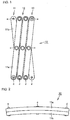
- An extendable arm 10 is formed by a plurality of cross units 11, 12, 13 arranged in one direction and pivotally coupled to each other. Since the plurality of cross units 11, 12, 13 have the same structure, one cross unit 11 will be described representatively in order to avoid repetitive description.
- the cross unit 11 is formed by two rigid members 11a, 11b that are pivotally coupled at a central coupling point c so as to cross over each other to form an X-shape.
- Each rigid member 11a, 11b has coupling points d, e at both ends thereof.
- each rigid member 11a, 11b has such a curved shape that the coupling points d, e at both ends thereof are shifted toward one side from a longitudinal axis passing through the central coupling point c.
- the distance between the central coupling point c and the coupling point d at one end is the same as that between the central coupling point c and the coupling point e at the other end.
- each rigid member 11a has a linear shape as viewed in plan, but is curved with a uniform radius of curvature along its entire longitudinal length as viewed from the front.
- the curvature is shown exaggerated in order to facilitate understanding.
- Each rigid member 11a is curved in the thickness direction, and the coupling points d, e at both ends are shifted by a distance L toward one side in the thickness direction from a longitudinal axis J passing through the central coupling point c and extending linearly in the longitudinal direction.
- Fig. 16 the curvature is shown exaggerated in order to facilitate understanding.
- Each rigid member 11a is curved in the thickness direction, and the coupling points d, e at both ends are shifted by a distance L toward one side in the thickness direction from a longitudinal axis J passing through the central coupling point c and extending linearly in the longitudinal direction.
- each rigid member 11a has such a curved shape that an axis T1 in the thickness direction which passes through the central coupling point c of the rigid member 11a and axes T2, T3 in the thickness direction which pass through the coupling points d, e at both ends of the rigid member 11a converge on the axis T1 in the thickness direction which passes through the central coupling point c.
- the direction of an axis in the thickness direction at each coupling point matches the axial direction of a shaft that pivotally couples at the coupling point two rigid members crossing over each other.
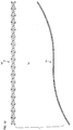
- the extendable arm 10 of the first embodiment extends linearly as viewed in plan when in the extended state. As shown in Fig. 4 , however, the extendable arm 10 is curved in the thickness direction with a uniform radius of curvature as viewed from the front when in the extended state. The radius of curvature of the curved surface in the extended state is substantially the same as the radius of curvature of each rigid member 11a.
- Fig. 17 shows another example of the rigid member for use in the extendable arm that is curved in the thickness direction.
- a rigid member 110 shown in Fig. 17 has a linear shape in its central region in the longitudinal direction, but is curved in the thickness direction at both ends, so that the overall shape of the rigid member 110 is a curved shape.
- the three axes in the thickness direction which pass through the central coupling point c and the coupling points d, e at both ends are converged at one point.
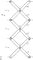
- an extendable arm 20 is formed by a plurality of cross units 21, 22, 23 arranged in one direction and pivotally coupled to each other.
- the cross unit 21 is formed by two rigid members 21a, 21b that have a curved shape as viewed in plan, namely that are curved in the lateral direction as viewed in plan, and that are pivotally coupled at the central coupling point c so as to cross over each other to form an X-shape.
- One rigid member 21a and the other rigid member 21b are curved in opposite directions to each other.
- one rigid member 21a has a curved shape that is convex to the left
- the other rigid member 21b has a curved shape that is convex to the right.
- the interval between the two rigid members 21a, 21b at one end (the upper end in Fig. 7 ) of the cross unit 21 is larger than that between the two rigid members 21a, 21b at the other end (the lower end in Fig. 7 ) of the cross unit 21.
- the overall shape of the extendable arm 20 is therefore a curved shape that is convex upward.
- each rigid member 21a, 21b has a curved shape (curved in the lateral direction) as viewed in plan in Fig. 10(a) , but has a linear shape with a uniform thickness as viewed from the front in Fig. 10(b) . Accordingly, in the extendable arm 20 formed by coupling the plurality of cross units 21, 22, 23, the upper and lower surfaces in the thickness direction of the extendable arm 20 are flat and parallel to each other, as shown in Fig. 8 .
- the extendable arm 20 when in the extended state, does not change in thickness in the thickness direction, and forms a curved shape that is large in the lateral direction.
- the coupling points d, e at both ends thereof are shifted by the distance L toward one side in the lateral direction from the longitudinal axis J passing through the central coupling point and extending linearly in the longitudinal direction.
- the rigid member 21a is curved with a uniform radius of curvature along its entire longitudinal length.
- Fig. 19 shows another example of the rigid member for use in the extendable arm that is curved in the lateral direction.
- a rigid member 210 shown in Fig. 19 has a linear shape in its central region in the longitudinal direction, but is curved in the lateral direction at both ends, so that the overall shape of the rigid member 210 is a curved shape.
- a line that passes through the central coupling point c and the coupling points d, e at both ends is curved.
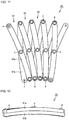
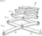
- an extendable arm 30 of the present embodiment is formed by a plurality of cross units 31, 32, 33 arranged in one direction and pivotally coupled to each other.
- each rigid member 31a, 31b forming the cross unit 31 is formed so that the coupling points d, e at both ends thereof are shifted toward one side from a longitudinal axis passing through the central coupling point c.
- Each rigid member 31a, 31b of the present embodiment is curved in the thickness direction and in the lateral direction.
- Fig. 15(a) is a plan view of one rigid member 31a. As shown in the figure, a longitudinal axis J1 that passes through the coupling points d, e at both ends is shifted by a distance L1 from a longitudinal axis J2 that passes through the central coupling point c, as viewed in plan.
- one rigid member 31a and the other rigid member 31b of the cross unit 31 are curved in opposite directions to each other.
- one rigid member 31a has a curved shape that is convex to the right
- the other rigid member 31b has a curved shape that is convex to the left. Accordingly, the interval between the two rigid members 31a, 31b at one end (the upper end in the figure) of the cross unit 31 is larger than that between the two rigid members 31a, 31b at the other end (the lower end in the figure) of the cross unit 31.
- the overall shape of the extendable arm 30 is therefore a curved shape that is convex upward.
- each rigid member 31a, 31b is curved also in the thickness direction.
- a longitudinal axis J3 that passes through the coupling points d, e at both ends is shifted by a distance L2 from a longitudinal axis J4 that passes through the central coupling point c.
- the rigid member 31a is shaped so as to protrude in the lateral direction at the coupling points d, e at both ends. Namely, the rigid member 31a is curved in the lateral direction. The rigid member 31a is uniformly curved with a fixed radius of curvature along its entire longitudinal length. As shown in Fig. 15(b) , the rigid member 31a is shaped so as to protrude in the thickness direction at the coupling points d, e at both ends. Namely, the rigid member 31a is curved in the thickness direction. The rigid member 31a is uniformly curved with a fixed radius of curvature along its entire longitudinal length.
- Fig. 13 shows the extendable arm 30 in a slightly extended state
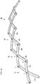
- Fig. 14 shows the extendable arm 30 in a greatly extended state.
- the extendable arm 30 in the extended state has a curved shape that is convex in the lateral direction in its central portion as viewed from above, and has a curved shape that is convex upward in its central portion as viewed from the front.
- the extent to which the extendable arm is curved may be changed as appropriate and the overall length may also be changed as appropriate so that the extendable arm 30 substantially forms a part of a conical surface when in a deployed state.
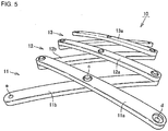
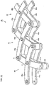
- Fig. 20 shows an extendable arm 40 according to a fourth embodiment of the present invention.
- Each rigid member 41a, 41b forming cross units 41 of the extendable arm 40 is shaped so as not to be curved in the thickness direction but to be curved only in the lateral direction.
- the extendable arm 40 of the present embodiment has a structure in which a pair of cross units 41 having the same structure are placed at an interval in the thickness direction and spacers 46 are placed therebetween to maintain the interval.
- the spacers 46 are located at the coupling points c, d, e.
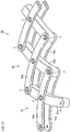
- Fig. 21 shows an extendable arm 50 according to a fifth embodiment of the present invention.
- Each rigid member 51a, 51b forming cross units 51 of the extendable arm 50 is shaped so as not to be curved in the thickness direction but to be curved only in the lateral direction.
- a pair of one rigid members 51a are provided at an interval in the thickness direction, and the other rigid member 51b is interposed between the pair of rigid members 51a and attached thereto.
- the extendable arm 40 of Fig. 20 and the extendable arm 50 of Fig. 21 have higher strength because at least the one rigid members are provided in pairs.
- the extendable arm may be designed to have any curved shape when in the extended state, such as an arc shape, a helical shape, or a wave shape, by devising the shape of each rigid member or combining as appropriate cross units formed by rigid members having different shapes.
- the extendable arm may be formed so that a three-dimensional shape formed by the extendable arm in a deployed state forms a part of a cylindrical surface, a part of a conical surface, or a part of a spherical surface.
- the extendable arm that is extended and contracted in a curved shape can be used in many applications.
- Figs. 22(a) and 22(b) show an embodiment in which an extendable arm forms an S-shaped curved line when in a deployed state.
- Fig. 22(a) is a plan view
- Fig. 22(b) is a front view.
- every rigid member except those of a cross unit CX located at an intermediate position is slightly curved in the thickness direction.
- the rigid members of the cross unit CX located at the intermediate position are not curved.
- the rigid members of the cross units located on the left side of the intermediate position in the figure have a curved shape that is convex upward, and the rigid members of the cross units located on the right side of the intermediate position in the figure have a curved shape that is convex downward.
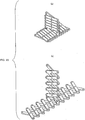
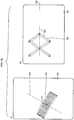
- Figs. 23(a) and 23(b) show an embodiment in which an extendable arm branches at an intermediate position.
- Fig. 23(a) shows a contracted state
- Fig. 23(b) shows a slightly extended state.
- Figs. 23(a) and 23(b) are shown in order to illustrate how the extendable arm branches, and each rigid member forming cross units is shown to have a non-curved shape for convenience of illustration. In the embodiment of the present invention, however, each rigid member is curved in the thickness direction or the lateral direction or in both directions.
- a vertically extending portion branches off from an intermediate position of a horizontally extending portion. Both ends of the cross unit located at an end of the vertically extending portion are coupled to both ends of the cross unit located at the intermediate position of the horizontally extending portion. Accordingly, when the horizontal portion of the extendable arm is extended from a contracted state, the vertical portion of the extendable arm is also shifted from a contracted state to an extended state accordingly.
- the extendable arm may branch in the vertical direction at the horizontal portion, or may branch in the horizontal direction at the horizontal portion.
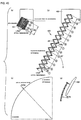
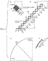
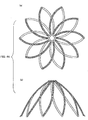
- Figs. 24(a) and 24(b) show an embodiment in which each rigid member forming cross units is greatly curved in the thickness direction so as to form an arc shape.
- Fig. 24(a) shows a contracted state
- Fig. 24(b) shows an extended state.
- the extendable arm forms a part of a spherical surface when in a deployed state.
- each rigid member may be more greatly curved in the thickness direction so as to form a semicircular arc with an included angle of 180 degrees.
- the extendable arm forms a spherical surface when in a deployed state.
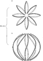
- Figs. 43(a) and 43(b) show an example in which the extendable arm forms a sphere.
- Fig. 43(a) is a plan view
- Fig. 43(b) is a front view.
- Each rigid member is greatly curved in the thickness direction so as to form a semicircular arc measuring about 180 degrees.
- Figs. 44(a) and 44(b) show an example in which the extendable arm forms a cone.
- Fig. 44(a) is a plan view
- Fig. 44(b) is a front view.
- Each rigid member is curved in both the thickness and lateral directions.
- each rigid member is curved in both the thickness and lateral directions, and one of each pair of rigid members is made longer than the other rigid member.
- Figs. 25 to 30 are illustrations showing examples of use of the extendable arm.
- Figs. 25(a) and 25(b) show an example of using an extendable arm 60 for a desk lamp.
- Fig. 25(a) shows the extendable arm 60 in a contracted state
- Fig. 25(b) shows the extendable arm 60 in an extended state.
- a lighting unit 61 is attached to the tip end of the extendable arm 60.
- the extendable arm 60 is placed on a desk.
- the extendable arm 60 has a greatly curved shape when in the extended state. This can ensure a large work space under the extendable arm 60.
- Fig. 26 shows an example of using an extendable arm 62 for a clothes hanger.
- the extendable arm 62 has a curved shape when in an extended state. Accordingly, attaching hangers or hooks 63 at different positions of the extendable arm 62 allows clothes etc. to be hung at various heights.
- a plurality of extendable arms with various shapes may be combined as appropriate in order to change the vertical heights of the plurality of attachment positions of the hangers or hooks or to shift the horizontal positions of the attachment positions of the hangers or hooks.
- Figs. 27(a) and 27(b) show an example of using an extendable arm 64 for a beverage tray on an armrest 65 of a seat.
- a beverage holder 66 is attached to the tip end of the extendable arm 64.
- Fig. 27(a) when the extendable arm 64 is in a contracted state, a large space is ensured in front of the seat.
- Fig. 27(b) when the extendable arm 64 is extended, the beverage holder 66 is located in front of a seated person.
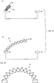
- Fig. 28 shows an example of using an extendable arm 67 for an arched bridge.
- Fig. 29 shows an example of using an extendable arm 68 for a decoration rail for a Christmas tree.
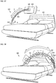
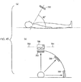
- Figs. 30(a) and 30(b) show an example of using an extendable arm 69 for a visual object holding device that is attached to a bed.
- the extendable arm 69 When in an extended state, the extendable arm 69 has a greatly curved shape from the side of the bed to a position above the face of a person lying on the bed. Accordingly, attaching to the extendable arm 68 a holder for a visual object such as a book or an information display device allows the person to easily read and look at the visual object.
- the extendable arm can be designed to have any curved shape when in the extended state, such as an arc shape, a helical shape, or a wave shape, by devising the shape of each rigid member or combining as appropriate cross units formed by rigid members having different shapes.
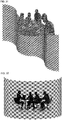
- Fig. 31 shows an example of a partition, in which a plurality of extendable arms are coupled in the lateral direction crossing the longitudinal direction so that the partition extends in the vertical and horizontal directions and has a large area.
- the illustrated partition has a wave-like curved shape for improved design.
- Fig. 32 shows an example of a partition in the form of a cylindrical surface
- Fig. 33 shows an example of a partition in the form of a spherical surface.
- a partition in any form can be produced by devising the shape of the rigid members as appropriate.
- FIG. 34 shows an example of a desk lamp using an extendable arm according to an embodiment of the present invention.
- a desk lamp 300 includes an extendable arm 302 according to an embodiment of the present invention, a base member 301 supporting the base end of the extendable arm 302 and containing a power supply control unit, a lighting unit 303 attached to the tip end of the extendable arm 302, and an electrical cord (not shown) extending from the base member 301 to the lighting unit 303.
- the coupling points at both ends of each rigid member forming cross units are shifted in the lateral direction of the rigid member, and the direction in which the lighting unit 303 emits light is the same regardless of whether the extendable arm 302 is in an extended state or in a contracted state.
- Fig. 34 shows three states of the extendable arm 302, namely a contracted state, an intermediate state, and an extended state, in an overlapping manner.
- the lighting unit 303 always emits light in a direction perpendicular to the surface of a desk regardless of the position of the extendable arm 302.
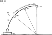
- FIG. 35 shows another example of the desk lamp using an extendable arm according to another embodiment of the present invention.
- a desk lamp 310 includes an extendable arm 312, a base member 311 supporting the base end of the extendable arm 312 and containing a power supply control unit, a lighting unit 313 attached to the tip end of the extendable arm 312, and an electrical cord (not shown) extending from the base member 311 to the lighting unit 313.
- the coupling points at both ends of each rigid member forming cross units are shifted in the thickness direction of the rigid member.
- the radius of curvature of the extendable arm 312 is the same regardless of whether the extendable arm 312 is in an extended state or in a contracted state.
- the lighting unit 313 therefore emits light to the same position on a desk regardless of whether the extendable arm 312 is in the extended state or in the contracted state.
- Fig. 35 shows an example of the desk lamp
- the present invention may be applied to a laser radiation device by using a similar configuration.
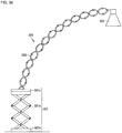
- FIG. 36 shows still another example of the desk lamp.
- An illustrated desk lamp 320 includes a base unit 321, an extendable arm 322 according to an embodiment of the present invention, which has its base end supported by the base unit 321, and a lighting unit 323 attached to the tip end of the extendable arm 322.
- the coupling points at both ends of each rigid member forming the extendable arm 322 are shifted in the lateral direction of the rigid member.
- the direction in which the lighting unit 323 emits light is the same regardless of whether the extendable arm 322 is in an extended state or in a contracted state.
- the base unit 321 of the desk lamp shown in Fig. 36 includes a base member 321a that is placed directly on a desk, an upper plate 321c that directly supports the base end of the extendable arm 322, and an extendable arm 321b that couples the base member 321a and the upper plate 321c.
- the extendable arm 321b has a conventional structure.
- a cross unit is formed by two linear plate members that are crossed over each other at their centers to form an X-shape. Such cross units are coupled in the vertical direction so that the extendable arm 321b can be linearly extended and contracted in the vertical direction.
- the extendable arm 322 and the lighting unit 323 can be translated in the vertical direction by extending and contracting the extendable arm 321b.
- the plate member supports the pair of rigid members in such a state that shifting of the rigid members is permitted, so that a change in interval between the pair of rigid members is permitted.
- the electrical cord that couples the base member and the lighting unit is configured to extend through the extendable arm within the range of the thickness of the extendable arm.
- Various structures can be used to implement this configuration.
- the extendable arm having the shape shown in Fig. 20 there is clearance between the upper and lower cross units. Accordingly, the electrical cord is placed to extend through the clearance.
- a recess or hole may be formed in the rigid members so that the electrical cord extends therethrough.
- FIG. 37 shows an example of a bed structure with an extendable arm, which uses an extendable arm according to an embodiment of the present invention.
- a structure 330 shown in Fig. 37 includes a bed 331, a base member 332 fixed to the bed 331, and an extendable arm 333 having its base end supported by the base member 332 and having an article holding unit 334 at its tip end.
- the article holding unit 334 holds a visual object 335 such as a touch panel display or a television display.
- the base end of the extendable arm 333 is rotatable about the longitudinal axis of the cylindrical base member 332, as shown by arrow A.
- the article holding unit 334 rotatably holds the display 335 as shown by arrow C so that a person lying on the bed can change the angle of the visual object 335 as necessary.
- the extendable arm 333 can be extended and contracted as shown by arrow B.
- the extendable arm 333 is formed by a plurality of cross units arranged in one direction and pivotally coupled to each other, and each of the cross units is formed by two rigid members that are pivotally coupled at the central coupling point so as to cross over each other to form an X-shape.
- each rigid member In order for the extendable arm to follow a curved-line path when being extended and contracted, each rigid member has such a curved shape that the coupling points at both ends thereof are shifted toward one side from a longitudinal axis passing through the central coupling point.
- the coupling points at both ends of each rigid member are shifted in the thickness direction of the rigid member. Accordingly, the visual object 335 held by the article holding unit 334 can always provide a visual surface facing toward the face of the person lying on the bed, regardless of whether the extendable arm 333 is in the extended state or in the contracted state.
- Fig. 38 shows another example of the bed structure with the extendable arm.
- a first extendable arm 341 extends from one side of the bed
- a second extendable arm 342 extends from the other side of the bed.
- the tip end of the first extendable arm 341 and the tip end of the second extendable arm 342 are coupled to a common article holding unit 343.
- the article holding unit 343 holds a visual object 344.
- the visual object 344 can be moved in a wide range from one side to the other side of the bed.
- Fig. 39 shows two examples of an article holding device.
- One article holding device 350 holds a lighting unit 353, and the other article holding device 360 holds a touch panel display 363.
- the one article holding device 350 includes a base member 351 fixed to a piece of furniture 355 such as a bookshelf, and an extendable arm 352 having its base end supported by the base member 351 and holding the lighting unit 353 at its tip end.
- the other article holding device 360 includes a base member 361 fixed to the piece of furniture 355 such as a bookshelf, and an extendable arm 362 having its base end supported by the base member 361 and holding the touch panel display 363 at its tip end.
- Figs. 40(a) to 40(d) show an example of a television display holding device 400 using an extendable arm 401 including 13 cross links. Specific dimensions are shown in the figures by way of example.
- a television display 402 is attached to the tip end of the extendable arm 401.
- the coupling points at both ends of each rigid member are shifted in the thickness direction of the rigid member. Accordingly, the radius of curvature of the extendable arm 401 is the same regardless of whether the extendable arm 401 is in an extended state or in a contracted state.
- the extendable arm 401 has a length of 156 mm when in the most contracted state.
- Figs. 40(b) and 40(c) show the extendable arm 401 extended to such an extent that the television display 402 is located at the highest position (angle of 90 degrees).
- the radius of curvature of the extendable arm 401 is 704 mm, and the interval between adjoining ones of the cross links is 79.2 mm.
- the angle between a pair of rigid members forming a single cross link is 110.0°.
- Figs. 41(a) to 41(d) show a television display holding device 500 that supports a television display 502 by an extendable arm 501 including 10 cross links.
- the coupling points at both ends of each rigid member are shifted in the thickness direction of the rigid member. Accordingly, the radius of curvature of the extendable arm 501 is the same regardless of whether the extendable arm 501 is in an extended state or in a contracted state.
- the extendable arm 501 has a length of 120 mm when in the most contracted state.
- Figs. 41(b) and 41(c) show the extendable arm 501 extended to such an extent that the television display 502 is located at the highest position (angle of 90 degrees).
- the radius of curvature of the extendable arm 501 is 704 mm, and the interval between adjoining ones of the cross links is 105.7 mm.
- the angle between a pair of rigid members forming a single cross link is 80.0°.
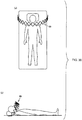
- Figs. 45 to 46 show an example in which the article holding device is applied to a visual object holding device. Specifically, Figs. 45 to 46 show an example in which a visual object holding device is attached to a bed. As shown in Fig. 45(a) , a person lying on the bed can easily look at a visual object 700 when the trajectory of the extension/contraction operation of the extendable arm forms an angle of substantially 60 degrees with respect to a horizontal plane.
- each rigid member forming an extendable arm is preferably curved in the thickness direction.
- the visual object can provide a visual surface extending perpendicular to the face of the person lying on the bed as shown in Fig. 46(b) , regardless of whether the extendable arm is in an extended state or in a contracted state.
- a coupling structure of the extendable arm and an article holding member is preferably configured so that the angle of the article holding member with respect to the longitudinal axis of the extendable arm changes according to the extraction/contraction operation of the extendable arm. If the extendable arm is in the most contracted state and the visual object 700 is located on the lateral side of the person lying on the bed, the visual surface of the visual object 700 is located at such an angular position that the person lying on his/her side on the bed can easily look at the visual object 700.
- a central transverse line 702 of the visual surface of the visual object 700 is substantially parallel to a longitudinal axis 701 of the extendable arm, whereby the person lying on the bed can easily look at the visual object 700.
- FIG. 46(a) and 46(b) show a joint portion of the extendable arm and the visual object.
- Fig. 46(a) shows the extendable arm in a contracted state
- Fig. 46(b) shows the extendable arm in an extended state.
- one rigid member 703 located at the tip end of the extendable arm is coupled at a fixed angle to a visual object 704.
- the visual object 704 coupled at the fixed angle to the rigid member 703 is also changed in angle with respect to the longitudinal axis 705 of the extendable arm accordingly.
- the angle of the visual object is changed by using a change in angle of the rigid member located at the tip end.
- the angle of the visual object may be changed according to a change in extension/contraction length of the extendable arm, or the angle of the visual object may be changed by using a gear etc. that operates according to the extension/contraction operation of the extendable arm.
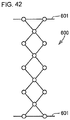
- one end of the extendable arm is attached to a base member, and the other end thereof is attached to an article holding unit.
- the interval between the ends of a pair of rigid members located at each of the base and tip ends of the extendable arm changes according to the extended/contracted state of the extendable arm.
- Fig. 42 illustrates joint portions at both ends of an extendable arm 600.
- the ends of the pair of rigid members located at each extreme end in the longitudinal direction of the extendable arm 600 are slidably supported on a bar-shaped member 601.
- the angle of at least one cross link is fixed or the positions of the coupling points of adjoining ones of the rigid members are fixed.
- the material forming the extendable arm is not particularly limited.
- Examples of the material forming the extendable arm include a metal, plastic, wood, ceramic, hard rubber, a composite material thereof, etc.
- the extendable arm can be used in various applications. Exemplary applications are listed below.
- the present invention can be advantageously used as an extendable arm capable of stably forming a curved shape in a balanced manner.
Landscapes
- Engineering & Computer Science (AREA)
- General Engineering & Computer Science (AREA)
- Mechanical Engineering (AREA)
- Robotics (AREA)
- Manipulator (AREA)
- Non-Portable Lighting Devices Or Systems Thereof (AREA)
- Pivots And Pivotal Connections (AREA)
- Arrangement Of Elements, Cooling, Sealing, Or The Like Of Lighting Devices (AREA)
Applications Claiming Priority (3)
| Application Number | Priority Date | Filing Date | Title |
|---|---|---|---|
| JP2013013269 | 2013-01-28 | ||
| JP2013239210A JP5837023B2 (ja) | 2013-01-28 | 2013-11-19 | 伸縮アームおよび伸縮アームを用いた構造物 |
| PCT/JP2013/082655 WO2014115428A1 (ja) | 2013-01-28 | 2013-12-05 | 伸縮アームおよび伸縮アームを用いた構造物 |
Publications (3)
| Publication Number | Publication Date |
|---|---|
| EP2949434A1 EP2949434A1 (en) | 2015-12-02 |
| EP2949434A4 EP2949434A4 (en) | 2016-11-02 |
| EP2949434B1 true EP2949434B1 (en) | 2019-02-20 |
Family
ID=51227231
Family Applications (1)
| Application Number | Title | Priority Date | Filing Date |
|---|---|---|---|
| EP13872717.7A Active EP2949434B1 (en) | 2013-01-28 | 2013-12-05 | Telescopic arm and structure using telescopic arm |
Country Status (7)
| Country | Link |
|---|---|
| US (1) | US9316350B2 (enExample) |
| EP (1) | EP2949434B1 (enExample) |
| JP (1) | JP5837023B2 (enExample) |
| KR (1) | KR102099628B1 (enExample) |
| CN (1) | CN104540649B (enExample) |
| TW (1) | TWI585331B (enExample) |
| WO (1) | WO2014115428A1 (enExample) |
Families Citing this family (39)
| Publication number | Priority date | Publication date | Assignee | Title |
|---|---|---|---|---|
| CN104369180A (zh) * | 2014-10-20 | 2015-02-25 | 佛山市禾才科技服务有限公司 | 一种四边形复合机械臂 |
| CN104608147A (zh) * | 2014-12-09 | 2015-05-13 | 佛山市禾才科技服务有限公司 | 一种弯曲伸缩的机械臂 |
| CN104712174A (zh) * | 2015-01-14 | 2015-06-17 | 佛山市禾才科技服务有限公司 | 一种可伸缩折叠的立体结构 |
| JP5996713B1 (ja) * | 2015-04-30 | 2016-09-21 | 株式会社不二宮製作所 | 伸縮アームを用いた面積可変枠体及び体積可変立体構造物 |
| CN105380458A (zh) * | 2015-11-25 | 2016-03-09 | 宁波市新光货架有限公司 | 一种改进型壁挂轻型货架 |
| CN105380457A (zh) * | 2015-11-25 | 2016-03-09 | 宁波市新光货架有限公司 | 一种壁挂轻型货架 |
| US10228100B2 (en) * | 2015-12-01 | 2019-03-12 | Philips Lighting Holding B.V. | Lighting device and lighting system |
| CN105526246A (zh) * | 2016-01-22 | 2016-04-27 | 佛山市禾才科技服务有限公司 | 一种可收缩的剪式付组半圆面和弧面 |
| CN107237549A (zh) * | 2016-03-28 | 2017-10-10 | 佛山市禾才科技服务有限公司 | 一种可变尺寸的四边形安全护栏 |
| CN107237548A (zh) * | 2016-03-28 | 2017-10-10 | 佛山市禾才科技服务有限公司 | 一种可变尺寸的三边形安全护栏 |
| KR101812134B1 (ko) * | 2016-04-11 | 2017-12-27 | 아이투엠 주식회사 | 외형이 변형되는 주름형상의 갓을 갖는 조명기구 |
| JP6456881B2 (ja) * | 2016-07-19 | 2019-01-23 | 株式会社不二宮製作所 | 伸縮アームを用いた形状可変立体構造物 |
| JP6391124B2 (ja) | 2016-08-08 | 2018-09-19 | 株式会社不二宮製作所 | 伸縮アームを用いた形状可変立体構造物 |
| JP6391125B2 (ja) | 2016-08-22 | 2018-09-19 | 株式会社不二宮製作所 | 伸縮アームを用いた形状可変枠体 |
| JP6341578B2 (ja) | 2016-12-06 | 2018-06-13 | 株式会社不二宮製作所 | 形状可変枠体および形状可変立体構造物 |
| CN108237523B (zh) * | 2016-12-23 | 2024-11-19 | 佛山顺德光启尖端装备有限公司 | 机器人伸脖子装置及具有其的机器人 |
| US10093226B1 (en) * | 2017-08-09 | 2018-10-09 | Ford Global Technologies, Llc | Deployable vehicle light assembly |
| CN107504446A (zh) * | 2017-10-19 | 2017-12-22 | 湖州明日照明科技有限公司 | 一种多功能折叠式照明灯具 |
| CN108161898A (zh) * | 2017-12-25 | 2018-06-15 | 佛山市禾才科技服务有限公司 | 一种类桁架式机械臂 |
| JP6943440B2 (ja) | 2018-04-17 | 2021-09-29 | 株式会社不二宮製作所 | 伸縮アーム構造体 |
| CN108730712A (zh) * | 2018-08-23 | 2018-11-02 | 吉林合纵信息技术有限公司 | 一种平板电脑支架 |
| CN109036074A (zh) * | 2018-08-30 | 2018-12-18 | 溧阳市科创电子电器有限公司 | 一种便于制作伸缩拳 |
| US12031663B1 (en) * | 2019-02-25 | 2024-07-09 | Russ Bassett Corporation | Array with lateral movement |
| JP6860224B2 (ja) | 2019-03-04 | 2021-04-14 | 株式会社不二宮製作所 | 伸縮アーム |
| CN109882723B (zh) * | 2019-04-02 | 2024-02-23 | 安徽理工大学 | 一种嵌入式壁挂安装装置及具有其的壁挂式设备 |
| US11491645B2 (en) * | 2019-06-07 | 2022-11-08 | Massachusetts Institute Of Technology | Scissor linkage design and method of operation |
| JP2020199568A (ja) | 2019-06-07 | 2020-12-17 | 株式会社不二宮製作所 | 伸縮アーム、形状可変枠体および形状可変立体構造物 |
| CN110151433B (zh) * | 2019-07-03 | 2020-10-30 | 河南省中医院(河南中医药大学第二附属医院) | 一种icu病床专用床头卡 |
| CN110939846B (zh) * | 2019-12-16 | 2021-03-23 | 成都市舒是智能家居有限公司 | 一种支架组件的控制方法 |
| US11131112B2 (en) * | 2020-02-19 | 2021-09-28 | Zenithen USA, LLC | Expandable canopy tent frame |
| US11690951B1 (en) * | 2020-04-03 | 2023-07-04 | The Cleveland Clinic Foundation | IV tubing carriage system |
| JP6937527B1 (ja) * | 2020-05-15 | 2021-09-22 | 株式会社不二宮製作所 | 屈曲部材を備える視覚的興味刺激構造体 |
| US20220330519A1 (en) * | 2021-04-20 | 2022-10-20 | John Chitkowski | Elevatable pet bed platform assembly |
| CN113230078B (zh) * | 2021-06-10 | 2022-06-28 | 上海长征医院 | 一种颈椎手术操作中病患头部固定装置 |
| CN113466763B (zh) * | 2021-07-19 | 2023-07-25 | 广东电网有限责任公司 | 超导电缆变径弯曲测试装置及其测试方法 |
| CN215982185U (zh) * | 2021-09-16 | 2022-03-08 | 深圳北极之光科技有限公司 | 一种可伸缩的led植物灯 |
| US12011108B1 (en) | 2021-11-17 | 2024-06-18 | Marcus-Alan Asher Brown | Adjustable hanger |
| JP7194477B1 (ja) * | 2022-01-31 | 2022-12-22 | 株式会社不二宮製作所 | 複数の連結部を備える連結構造体および形状可変部材 |
| JP1745941S (enExample) * | 2022-11-30 | 2023-06-09 |
Family Cites Families (28)
| Publication number | Priority date | Publication date | Assignee | Title |
|---|---|---|---|---|
| DE8303281U1 (de) * | 1983-09-15 | Herzog, Thomas, Prof. Dr., 8000 München | Scherengitter zur Erzeugung von Verstellbewegungen | |
| US2013882A (en) * | 1933-07-14 | 1935-09-10 | Robert B Francis | Bed attachment |
| DE807286C (de) * | 1948-11-16 | 1951-06-28 | Cosack O H G Geb | Scherenarm |
| US3168791A (en) * | 1961-08-28 | 1965-02-09 | Donald W Nutting | Book holder |
| JPS5033126U (enExample) * | 1973-07-21 | 1975-04-10 | ||
| JPS5427272Y2 (enExample) * | 1975-06-24 | 1979-09-05 | ||
| JPS54117081U (enExample) | 1978-02-03 | 1979-08-16 | ||
| JPS57107788A (en) * | 1980-12-26 | 1982-07-05 | Tokyo Shibaura Electric Co | Extensible arm |
| JPS613409U (ja) * | 1984-06-13 | 1986-01-10 | 日立造船株式会社 | 伸縮ア−ム |
| JPH0641119B2 (ja) * | 1986-01-20 | 1994-06-01 | 日本電信電話株式会社 | マニピユレ−タ |
| JPH0234729Y2 (enExample) | 1987-07-28 | 1990-09-19 | ||
| JPH01159036A (ja) | 1987-12-15 | 1989-06-22 | Kao Corp | 乳化組成物の製造法 |
| JPH01159036U (enExample) | 1988-04-25 | 1989-11-02 | ||
| JP3274754B2 (ja) * | 1993-09-30 | 2002-04-15 | 日本エステル株式会社 | 目ずれ防止効果を有する太細糸 |
| JPH11151124A (ja) * | 1997-11-25 | 1999-06-08 | Mimoto:Kk | 患者用のテレビ支持金具 |
| US6061923A (en) * | 1998-12-03 | 2000-05-16 | Case; Agnes G. | Wall-mounted extendable hair dryer holder |
| DE19923257A1 (de) * | 1999-05-20 | 2000-11-23 | Sabine Wald | Variables Scherengittergestell |
| EP1223378A1 (de) * | 2001-01-15 | 2002-07-17 | Oliver Michl | Scherengitter |
| JP2006052603A (ja) | 2004-08-16 | 2006-02-23 | Takanori Hatanaka | 伸縮構造体ならびに折り畳み式梯子、折り畳み式支持台、折り畳み式器具および折り畳み式パイプ |
| USD555202S1 (en) * | 2005-03-10 | 2007-11-13 | Cri2000, Lp | Expandable document holder |
| US8733453B2 (en) | 2007-12-21 | 2014-05-27 | Schlumberger Technology Corporation | Expandable structure for deployment in a well |
| US8291781B2 (en) | 2007-12-21 | 2012-10-23 | Schlumberger Technology Corporation | System and methods for actuating reversibly expandable structures |
| US7896088B2 (en) | 2007-12-21 | 2011-03-01 | Schlumberger Technology Corporation | Wellsite systems utilizing deployable structure |
| CN201131519Y (zh) * | 2007-12-27 | 2008-10-15 | 杭州银格旅游用品有限公司 | 折叠休闲床 |
| CN101744440A (zh) * | 2008-12-06 | 2010-06-23 | 刘运果 | 一种基于异形伞伞骨的新型x形伸缩节设计 |
| DE102009010933B4 (de) * | 2009-02-27 | 2016-05-04 | Christoph Niedeggen | Scherenarm zur Positionierung eines Leuchtenkopfes |
| AU2011275324A1 (en) | 2010-07-08 | 2013-01-24 | Nadav Gavish | A sheltering device |
| JP3174754U (ja) * | 2012-01-24 | 2012-04-05 | 碧芬 林 | 自動的に伸縮可能な照明構造 |
-
2013
- 2013-11-19 JP JP2013239210A patent/JP5837023B2/ja active Active
- 2013-12-05 WO PCT/JP2013/082655 patent/WO2014115428A1/ja not_active Ceased
- 2013-12-05 KR KR1020157004218A patent/KR102099628B1/ko active Active
- 2013-12-05 US US14/421,712 patent/US9316350B2/en active Active
- 2013-12-05 CN CN201380042763.6A patent/CN104540649B/zh active Active
- 2013-12-05 EP EP13872717.7A patent/EP2949434B1/en active Active
-
2014
- 2014-01-03 TW TW103100157A patent/TWI585331B/zh active
Non-Patent Citations (1)
| Title |
|---|
| None * |
Also Published As
| Publication number | Publication date |
|---|---|
| TW201437534A (zh) | 2014-10-01 |
| TWI585331B (zh) | 2017-06-01 |
| KR20150111901A (ko) | 2015-10-06 |
| US9316350B2 (en) | 2016-04-19 |
| CN104540649B (zh) | 2016-10-05 |
| EP2949434A4 (en) | 2016-11-02 |
| EP2949434A1 (en) | 2015-12-02 |
| JP2014159070A (ja) | 2014-09-04 |
| CN104540649A (zh) | 2015-04-22 |
| KR102099628B1 (ko) | 2020-04-10 |
| JP5837023B2 (ja) | 2015-12-24 |
| WO2014115428A1 (ja) | 2014-07-31 |
| US20150300560A1 (en) | 2015-10-22 |
Similar Documents
| Publication | Publication Date | Title |
|---|---|---|
| EP2949434B1 (en) | Telescopic arm and structure using telescopic arm | |
| USD581688S1 (en) | Chair | |
| USD577837S1 (en) | Christmas light | |
| USD592875S1 (en) | High back wood chair | |
| USD612066S1 (en) | Ceiling canopy | |
| JP6341578B2 (ja) | 形状可変枠体および形状可変立体構造物 | |
| USD842630S1 (en) | Display unit with built-in shelving supports | |
| CN102907905B (zh) | 一种多功能的桌子 | |
| US20070051858A1 (en) | Hanging chair stand | |
| JP5945458B2 (ja) | 複合ロクロの連動構造 | |
| CN202190942U (zh) | 床上用桌 | |
| CN2925227Y (zh) | 活动衣橱 | |
| US20080271483A1 (en) | Memorabilia and charm display | |
| CN102599755A (zh) | 一种折叠床 | |
| KR100617502B1 (ko) | 풍선 장식용 트리 유니트 | |
| JP2016042985A (ja) | デスクシステム | |
| CN203860864U (zh) | 一种改进型蚊帐 | |
| CN2263478Y (zh) | 置物装置 | |
| ES2293803B1 (es) | Salvamanteles. | |
| CN206380365U (zh) | 一种方便种植藤本植物的花盆 | |
| JP4733828B2 (ja) | 鉢植草花の自立型化粧枠体 | |
| USD44611S (en) | Design for | |
| TWM665205U (zh) | 裝飾品結構 | |
| TWM612360U (zh) | 多功能桌台 | |
| HK1263351A1 (en) | An integrated hinge for furniture |
Legal Events
| Date | Code | Title | Description |
|---|---|---|---|
| PUAI | Public reference made under article 153(3) epc to a published international application that has entered the european phase |
Free format text: ORIGINAL CODE: 0009012 |
|
| 17P | Request for examination filed |
Effective date: 20150710 |
|
| AK | Designated contracting states |
Kind code of ref document: A1 Designated state(s): AL AT BE BG CH CY CZ DE DK EE ES FI FR GB GR HR HU IE IS IT LI LT LU LV MC MK MT NL NO PL PT RO RS SE SI SK SM TR |
|
| AX | Request for extension of the european patent |
Extension state: BA ME |
|
| DAX | Request for extension of the european patent (deleted) | ||
| A4 | Supplementary search report drawn up and despatched |
Effective date: 20161004 |
|
| RIC1 | Information provided on ipc code assigned before grant |
Ipc: F16M 13/00 20060101ALI20160927BHEP Ipc: F16M 13/02 20060101ALI20160927BHEP Ipc: H04N 5/64 20060101ALI20160927BHEP Ipc: B25J 18/02 20060101AFI20160927BHEP Ipc: F21V 21/24 20060101ALI20160927BHEP |
|
| RIC1 | Information provided on ipc code assigned before grant |
Ipc: F21V 21/24 20060101ALI20170201BHEP Ipc: H04N 5/64 20060101ALI20170201BHEP Ipc: B25J 18/02 20060101AFI20170201BHEP Ipc: F16M 13/00 20060101ALI20170201BHEP Ipc: F16M 13/02 20060101ALI20170201BHEP |
|
| STAA | Information on the status of an ep patent application or granted ep patent |
Free format text: STATUS: EXAMINATION IS IN PROGRESS |
|
| 17Q | First examination report despatched |
Effective date: 20171010 |
|
| GRAP | Despatch of communication of intention to grant a patent |
Free format text: ORIGINAL CODE: EPIDOSNIGR1 |
|
| STAA | Information on the status of an ep patent application or granted ep patent |
Free format text: STATUS: GRANT OF PATENT IS INTENDED |
|
| INTG | Intention to grant announced |
Effective date: 20181109 |
|
| RIN1 | Information on inventor provided before grant (corrected) |
Inventor name: MATSUOKA, NORIMICHI |
|
| GRAS | Grant fee paid |
Free format text: ORIGINAL CODE: EPIDOSNIGR3 |
|
| GRAA | (expected) grant |
Free format text: ORIGINAL CODE: 0009210 |
|
| STAA | Information on the status of an ep patent application or granted ep patent |
Free format text: STATUS: THE PATENT HAS BEEN GRANTED |
|
| AK | Designated contracting states |
Kind code of ref document: B1 Designated state(s): AL AT BE BG CH CY CZ DE DK EE ES FI FR GB GR HR HU IE IS IT LI LT LU LV MC MK MT NL NO PL PT RO RS SE SI SK SM TR |
|
| REG | Reference to a national code |
Ref country code: GB Ref legal event code: FG4D |
|
| REG | Reference to a national code |
Ref country code: CH Ref legal event code: EP |
|
| REG | Reference to a national code |
Ref country code: DE Ref legal event code: R096 Ref document number: 602013051228 Country of ref document: DE |
|
| REG | Reference to a national code |
Ref country code: AT Ref legal event code: REF Ref document number: 1097582 Country of ref document: AT Kind code of ref document: T Effective date: 20190315 |
|
| REG | Reference to a national code |
Ref country code: IE Ref legal event code: FG4D |
|
| REG | Reference to a national code |
Ref country code: NL Ref legal event code: MP Effective date: 20190220 |
|
| REG | Reference to a national code |
Ref country code: LT Ref legal event code: MG4D |
|
| PG25 | Lapsed in a contracting state [announced via postgrant information from national office to epo] |
Ref country code: FI Free format text: LAPSE BECAUSE OF FAILURE TO SUBMIT A TRANSLATION OF THE DESCRIPTION OR TO PAY THE FEE WITHIN THE PRESCRIBED TIME-LIMIT Effective date: 20190220 Ref country code: NO Free format text: LAPSE BECAUSE OF FAILURE TO SUBMIT A TRANSLATION OF THE DESCRIPTION OR TO PAY THE FEE WITHIN THE PRESCRIBED TIME-LIMIT Effective date: 20190520 Ref country code: LT Free format text: LAPSE BECAUSE OF FAILURE TO SUBMIT A TRANSLATION OF THE DESCRIPTION OR TO PAY THE FEE WITHIN THE PRESCRIBED TIME-LIMIT Effective date: 20190220 Ref country code: PT Free format text: LAPSE BECAUSE OF FAILURE TO SUBMIT A TRANSLATION OF THE DESCRIPTION OR TO PAY THE FEE WITHIN THE PRESCRIBED TIME-LIMIT Effective date: 20190620 Ref country code: SE Free format text: LAPSE BECAUSE OF FAILURE TO SUBMIT A TRANSLATION OF THE DESCRIPTION OR TO PAY THE FEE WITHIN THE PRESCRIBED TIME-LIMIT Effective date: 20190220 Ref country code: NL Free format text: LAPSE BECAUSE OF FAILURE TO SUBMIT A TRANSLATION OF THE DESCRIPTION OR TO PAY THE FEE WITHIN THE PRESCRIBED TIME-LIMIT Effective date: 20190220 |
|
| PG25 | Lapsed in a contracting state [announced via postgrant information from national office to epo] |
Ref country code: LV Free format text: LAPSE BECAUSE OF FAILURE TO SUBMIT A TRANSLATION OF THE DESCRIPTION OR TO PAY THE FEE WITHIN THE PRESCRIBED TIME-LIMIT Effective date: 20190220 Ref country code: RS Free format text: LAPSE BECAUSE OF FAILURE TO SUBMIT A TRANSLATION OF THE DESCRIPTION OR TO PAY THE FEE WITHIN THE PRESCRIBED TIME-LIMIT Effective date: 20190220 Ref country code: BG Free format text: LAPSE BECAUSE OF FAILURE TO SUBMIT A TRANSLATION OF THE DESCRIPTION OR TO PAY THE FEE WITHIN THE PRESCRIBED TIME-LIMIT Effective date: 20190520 Ref country code: IS Free format text: LAPSE BECAUSE OF FAILURE TO SUBMIT A TRANSLATION OF THE DESCRIPTION OR TO PAY THE FEE WITHIN THE PRESCRIBED TIME-LIMIT Effective date: 20190620 Ref country code: GR Free format text: LAPSE BECAUSE OF FAILURE TO SUBMIT A TRANSLATION OF THE DESCRIPTION OR TO PAY THE FEE WITHIN THE PRESCRIBED TIME-LIMIT Effective date: 20190521 Ref country code: HR Free format text: LAPSE BECAUSE OF FAILURE TO SUBMIT A TRANSLATION OF THE DESCRIPTION OR TO PAY THE FEE WITHIN THE PRESCRIBED TIME-LIMIT Effective date: 20190220 |
|
| REG | Reference to a national code |
Ref country code: AT Ref legal event code: MK05 Ref document number: 1097582 Country of ref document: AT Kind code of ref document: T Effective date: 20190220 |
|
| PG25 | Lapsed in a contracting state [announced via postgrant information from national office to epo] |
Ref country code: DK Free format text: LAPSE BECAUSE OF FAILURE TO SUBMIT A TRANSLATION OF THE DESCRIPTION OR TO PAY THE FEE WITHIN THE PRESCRIBED TIME-LIMIT Effective date: 20190220 Ref country code: EE Free format text: LAPSE BECAUSE OF FAILURE TO SUBMIT A TRANSLATION OF THE DESCRIPTION OR TO PAY THE FEE WITHIN THE PRESCRIBED TIME-LIMIT Effective date: 20190220 Ref country code: AL Free format text: LAPSE BECAUSE OF FAILURE TO SUBMIT A TRANSLATION OF THE DESCRIPTION OR TO PAY THE FEE WITHIN THE PRESCRIBED TIME-LIMIT Effective date: 20190220 Ref country code: SK Free format text: LAPSE BECAUSE OF FAILURE TO SUBMIT A TRANSLATION OF THE DESCRIPTION OR TO PAY THE FEE WITHIN THE PRESCRIBED TIME-LIMIT Effective date: 20190220 Ref country code: IT Free format text: LAPSE BECAUSE OF FAILURE TO SUBMIT A TRANSLATION OF THE DESCRIPTION OR TO PAY THE FEE WITHIN THE PRESCRIBED TIME-LIMIT Effective date: 20190220 Ref country code: ES Free format text: LAPSE BECAUSE OF FAILURE TO SUBMIT A TRANSLATION OF THE DESCRIPTION OR TO PAY THE FEE WITHIN THE PRESCRIBED TIME-LIMIT Effective date: 20190220 Ref country code: RO Free format text: LAPSE BECAUSE OF FAILURE TO SUBMIT A TRANSLATION OF THE DESCRIPTION OR TO PAY THE FEE WITHIN THE PRESCRIBED TIME-LIMIT Effective date: 20190220 Ref country code: CZ Free format text: LAPSE BECAUSE OF FAILURE TO SUBMIT A TRANSLATION OF THE DESCRIPTION OR TO PAY THE FEE WITHIN THE PRESCRIBED TIME-LIMIT Effective date: 20190220 |
|
| REG | Reference to a national code |
Ref country code: DE Ref legal event code: R097 Ref document number: 602013051228 Country of ref document: DE |
|
| PG25 | Lapsed in a contracting state [announced via postgrant information from national office to epo] |
Ref country code: SM Free format text: LAPSE BECAUSE OF FAILURE TO SUBMIT A TRANSLATION OF THE DESCRIPTION OR TO PAY THE FEE WITHIN THE PRESCRIBED TIME-LIMIT Effective date: 20190220 Ref country code: PL Free format text: LAPSE BECAUSE OF FAILURE TO SUBMIT A TRANSLATION OF THE DESCRIPTION OR TO PAY THE FEE WITHIN THE PRESCRIBED TIME-LIMIT Effective date: 20190220 |
|
| PLBE | No opposition filed within time limit |
Free format text: ORIGINAL CODE: 0009261 |
|
| STAA | Information on the status of an ep patent application or granted ep patent |
Free format text: STATUS: NO OPPOSITION FILED WITHIN TIME LIMIT |
|
| PG25 | Lapsed in a contracting state [announced via postgrant information from national office to epo] |
Ref country code: AT Free format text: LAPSE BECAUSE OF FAILURE TO SUBMIT A TRANSLATION OF THE DESCRIPTION OR TO PAY THE FEE WITHIN THE PRESCRIBED TIME-LIMIT Effective date: 20190220 |
|
| 26N | No opposition filed |
Effective date: 20191121 |
|
| PG25 | Lapsed in a contracting state [announced via postgrant information from national office to epo] |
Ref country code: SI Free format text: LAPSE BECAUSE OF FAILURE TO SUBMIT A TRANSLATION OF THE DESCRIPTION OR TO PAY THE FEE WITHIN THE PRESCRIBED TIME-LIMIT Effective date: 20190220 |
|
| PG25 | Lapsed in a contracting state [announced via postgrant information from national office to epo] |
Ref country code: TR Free format text: LAPSE BECAUSE OF FAILURE TO SUBMIT A TRANSLATION OF THE DESCRIPTION OR TO PAY THE FEE WITHIN THE PRESCRIBED TIME-LIMIT Effective date: 20190220 |
|
| REG | Reference to a national code |
Ref country code: CH Ref legal event code: PL |
|
| REG | Reference to a national code |
Ref country code: BE Ref legal event code: MM Effective date: 20191231 |
|
| PG25 | Lapsed in a contracting state [announced via postgrant information from national office to epo] |
Ref country code: MC Free format text: LAPSE BECAUSE OF FAILURE TO SUBMIT A TRANSLATION OF THE DESCRIPTION OR TO PAY THE FEE WITHIN THE PRESCRIBED TIME-LIMIT Effective date: 20190220 |
|
| PG25 | Lapsed in a contracting state [announced via postgrant information from national office to epo] |
Ref country code: IE Free format text: LAPSE BECAUSE OF NON-PAYMENT OF DUE FEES Effective date: 20191205 Ref country code: LU Free format text: LAPSE BECAUSE OF NON-PAYMENT OF DUE FEES Effective date: 20191205 |
|
| PG25 | Lapsed in a contracting state [announced via postgrant information from national office to epo] |
Ref country code: CH Free format text: LAPSE BECAUSE OF NON-PAYMENT OF DUE FEES Effective date: 20191231 Ref country code: LI Free format text: LAPSE BECAUSE OF NON-PAYMENT OF DUE FEES Effective date: 20191231 Ref country code: BE Free format text: LAPSE BECAUSE OF NON-PAYMENT OF DUE FEES Effective date: 20191231 |
|
| PG25 | Lapsed in a contracting state [announced via postgrant information from national office to epo] |
Ref country code: CY Free format text: LAPSE BECAUSE OF FAILURE TO SUBMIT A TRANSLATION OF THE DESCRIPTION OR TO PAY THE FEE WITHIN THE PRESCRIBED TIME-LIMIT Effective date: 20190220 |
|
| PG25 | Lapsed in a contracting state [announced via postgrant information from national office to epo] |
Ref country code: HU Free format text: LAPSE BECAUSE OF FAILURE TO SUBMIT A TRANSLATION OF THE DESCRIPTION OR TO PAY THE FEE WITHIN THE PRESCRIBED TIME-LIMIT; INVALID AB INITIO Effective date: 20131205 Ref country code: MT Free format text: LAPSE BECAUSE OF FAILURE TO SUBMIT A TRANSLATION OF THE DESCRIPTION OR TO PAY THE FEE WITHIN THE PRESCRIBED TIME-LIMIT Effective date: 20190220 |
|
| PG25 | Lapsed in a contracting state [announced via postgrant information from national office to epo] |
Ref country code: MK Free format text: LAPSE BECAUSE OF FAILURE TO SUBMIT A TRANSLATION OF THE DESCRIPTION OR TO PAY THE FEE WITHIN THE PRESCRIBED TIME-LIMIT Effective date: 20190220 |
|
| PGFP | Annual fee paid to national office [announced via postgrant information from national office to epo] |
Ref country code: DE Payment date: 20241010 Year of fee payment: 12 |
|
| PGFP | Annual fee paid to national office [announced via postgrant information from national office to epo] |
Ref country code: GB Payment date: 20241010 Year of fee payment: 12 |
|
| PGFP | Annual fee paid to national office [announced via postgrant information from national office to epo] |
Ref country code: FR Payment date: 20250925 Year of fee payment: 13 |