WO2014103535A1 - シャッタ装置及び媒体取引装置 - Google Patents
シャッタ装置及び媒体取引装置 Download PDFInfo
- Publication number
- WO2014103535A1 WO2014103535A1 PCT/JP2013/080406 JP2013080406W WO2014103535A1 WO 2014103535 A1 WO2014103535 A1 WO 2014103535A1 JP 2013080406 W JP2013080406 W JP 2013080406W WO 2014103535 A1 WO2014103535 A1 WO 2014103535A1
- Authority
- WO
- WIPO (PCT)
- Prior art keywords
- gear
- shutter
- lock
- unit
- opening
- Prior art date
- Legal status (The legal status is an assumption and is not a legal conclusion. Google has not performed a legal analysis and makes no representation as to the accuracy of the status listed.)
- Ceased
Links
Images


Classifications
-
- G—PHYSICS
- G07—CHECKING-DEVICES
- G07D—HANDLING OF COINS OR VALUABLE PAPERS, e.g. TESTING, SORTING BY DENOMINATIONS, COUNTING, DISPENSING, CHANGING OR DEPOSITING
- G07D11/00—Devices accepting coins; Devices accepting, dispensing, sorting or counting valuable papers
- G07D11/10—Mechanical details
- G07D11/14—Inlet or outlet ports
-
- G—PHYSICS
- G07—CHECKING-DEVICES
- G07D—HANDLING OF COINS OR VALUABLE PAPERS, e.g. TESTING, SORTING BY DENOMINATIONS, COUNTING, DISPENSING, CHANGING OR DEPOSITING
- G07D9/00—Counting coins; Handling of coins not provided for in the other groups of this subclass
-
- G—PHYSICS
- G07—CHECKING-DEVICES
- G07D—HANDLING OF COINS OR VALUABLE PAPERS, e.g. TESTING, SORTING BY DENOMINATIONS, COUNTING, DISPENSING, CHANGING OR DEPOSITING
- G07D11/00—Devices accepting coins; Devices accepting, dispensing, sorting or counting valuable papers
-
- G—PHYSICS
- G07—CHECKING-DEVICES
- G07D—HANDLING OF COINS OR VALUABLE PAPERS, e.g. TESTING, SORTING BY DENOMINATIONS, COUNTING, DISPENSING, CHANGING OR DEPOSITING
- G07D13/00—Handling of coins or of valuable papers, characterised by a combination of mechanisms not covered by a single one of groups G07D1/00 - G07D11/00
Definitions
- the present invention relates to a shutter device and a medium transaction apparatus, and is suitable for application to, for example, an automatic cash transaction apparatus (ATM) that performs a desired transaction by inserting a medium such as banknotes.
- ATM automatic cash transaction apparatus
- a box-shaped banknote storage part for inserting a banknote for depositing in a banknote depositing / withdrawing part and a shutter for opening or closing the banknote storage part to the outside are provided.
- the shutter is opened, and the depositing process is performed by taking in the bill inserted into the bill storage unit by the user into the automatic teller machine.
- Some banknote depositing / withdrawing units prevent theft of cash stored inside the automatic teller machine by locking the shutter when closing the banknote storage part to the outside.
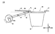
- the direct lock type banknote depositing and dispensing unit 210 includes a plate-shaped shutter 89 that slides between the opening 88 of the frame 87 and the banknote storage unit 22 in the front-rear direction, A drive unit 90 that rotates counterclockwise, a cam unit 90A that protrudes from a position off the central axis of the drive unit 90, and a pivot 91 that rotates clockwise or counterclockwise in the drawing, And a lock mechanism 92 that comes into contact with the cam portion 90A from above.
- the bill deposit / withdrawal unit 210 moves the cam unit 90A downward by rotating the drive unit 90 counterclockwise. Therefore, the lock mechanism 92 rotates counterclockwise around the support shaft 91, and the front end contacts the rear end of the shutter 89. As a result, the shutter 89 is locked, and rearward movement is restricted.
- the banknote deposit / withdrawal unit 210 moves the cam unit 90A upward by rotating the drive unit 90 clockwise.
- the lock mechanism 92 rotates clockwise around the support shaft 91, and the front end is released downward from the rear end of the shutter 89.
- the shutter 89 is unlocked and can be moved backward.
- the direct lock type banknote depositing / withdrawing unit locks the shutter 89 by directly contacting the lock mechanism 92
- the lock locking position PL where the lock mechanism 92 locks the shutter 89 is set to the shutter 89. It is necessary to provide in the vicinity (contact point between the lock mechanism 92 and the shutter 89).
- the present invention has been made in consideration of the above points, and intends to propose a shutter device and a medium transaction device that can enhance security.
- an opening / closing part for moving the shutter in an opening direction for opening a medium holding part for storing a medium taken in from the outside through an opening and a closing direction for closing from the outside;
- a driving unit having a driving force, and a gear unit that drives the opening and closing unit by contacting the driving unit and the opening and closing unit to rotate and transmitting the driving force of the driving unit to the opening and closing unit;
- a shutter locking / unlocking unit that regulates the operation of the opening / closing unit by regulating the rotation and locks the shutter in the closed state, while releasing the gear unit so that the opening / closing unit can be operated and the shutter is unlocked; It was made to provide.
- the lock locking position can be separated from the opening by contacting and locking the gear part that drives the opening / closing part that opens and closes the shutter, rather than contacting and locking the shutter itself. it can.
- a reception unit that receives a transaction relating to a paper-like medium, an opening direction that opens the medium storage unit that stores the medium taken in from the outside through the opening, and a closing direction that closes the medium from the outside
- the shutter is in the closed state by restricting the rotation of the opening and closing portion by contacting the gear portion and the gear portion to lock the shutter, while the shutter is locked by releasing the gear portion to enable the opening and closing portion to operate.
- a shutter locking / unlocking unit for releasing the image and a conveyance unit for conveying the medium accommodated in the reception medium accommodation unit by the reception unit.
- the lock locking position is separated from the opening by contacting and locking the gear part that drives the opening / closing part that opens and closes the shutter, instead of contacting and locking the shutter itself. Can do.
- the lock locking position is separated from the opening by contacting and locking the gear portion that drives the opening / closing portion that opens and closes the shutter, rather than contacting the shutter itself and locking. Can do.
- the present invention can realize a shutter device and a medium transaction device that can enhance security.
- the automatic teller machine 1 is configured with a box-shaped housing 19 as the center.
- the automatic teller machine 1 is installed in a financial institution or the like, and deposit transactions and withdrawal transactions with users. Transactions related to cash such as
- This automatic cash transaction apparatus 1 uses a cash card, banknote, bankbook, etc. as a transaction medium, and performs processing such as depositing, paying, and transferring cash by a user's operation.
- the housing 19 is provided with a customer service portion 9 at a position where it is easy to insert a bill or operate with a touch panel while the user is facing the front side, that is, an upper portion of the front surface.
- the customer service unit 9 is provided with a card entry / exit 2, a passbook entry / exit 3, a bill entry / exit 6, a coin entry / exit 7, and a display operation unit 8, and exchanges cash, a passbook, etc. directly with a user. At the same time, notification of information regarding transactions and reception of operation instructions are performed.
- a card processor for processing a user's cash card and the like, and a passbook processor (not shown) for recording transaction contents in a passbook are provided. Yes.
- the card processing machine processes the user's cash card taken from the card entry / exit 2 provided on the front surface (the surface facing the user) of the automatic cash transaction apparatus 1, and the passbook processing machine handles the automatic cash transaction
- the bankbook taken in from the bankbook entry / exit 3 provided in the front of the apparatus 1 is processed.
- a banknote depositing / dispensing machine 4 for processing banknotes and a coin depositing / dispensing machine 5 for processing coins are provided inside the automatic teller machine 1.
- a bill deposit / exit 6 exposed on the front surface of the automatic teller machine 1 is provided, and bills are deposited / withdrawn via the bill deposit / exit 6. Further, a coin inlet / outlet 7 exposed on the front surface of the automatic teller machine 1 is provided in front of the upper surface of the coin depositing / dispensing machine 5, and coins are deposited / withdrawn through the coin inlet / outlet 7.
- a display operation unit 8 is provided on the front side of the bill entrance / exit 6 and the coin entrance / exit 7 in the automatic teller machine 1.
- the display operation unit 8 includes, for example, a liquid crystal panel as a display unit and a touch panel as an operation unit, and can display various screens, input a personal identification number and a transaction amount.
- control unit (not shown) for controlling the whole is provided in a predetermined place in the case 19 of the automatic teller machine 1.
- the banknote depositing / dispensing machine 4 is a so-called recycling-type banknote depositing / dispensing machine that uses the deposited banknotes for withdrawal, and the banknote depositing / dispensing part 10, the discrimination part 11, and the temporary storage are on the upper part.
- the part 12 is arranged, and a plurality of bill storage boxes 13 and reject boxes 14 are arranged in the lower part.
- the banknote depositing / dispensing part 10 is arranged on the front side of the upper part of the banknote depositing / dispensing machine 4, and the banknote depositing / dispensing part 10 is provided with the banknote depositing / dispensing part 6 described above.
- a discrimination unit 11 is provided at the upper part of the banknote depositing / dispensing machine 4 at a position lower rearward of the banknote depositing / dispensing unit 10 to discriminate the authenticity, correctness, denomination, and conveyance state of the banknote.
- a temporary storage unit 12 for temporarily storing banknotes is disposed at a position on the upper rear side of the discrimination unit 11.
- a plurality of vertically long banknote storages 13 are arranged in the front-rear direction at the lower part of the banknote depositing / dispensing machine 4, and a reject box 14 is further arranged behind the last banknote storage 13.
- the banknote depositing / dispensing machine 4 is provided with a conveyance path 15 that connects the banknote depositing / dispensing section 10, the discrimination section 11, the temporary storage section 12, the plurality of banknote storage boxes 13, and the rejection box 14. A bill is conveyed to each part through.
- the banknote depositing / dispensing machine 4 having such a configuration, when a user inserts a banknote from the banknote depositing / unloading port 6 of the banknote depositing / dispensing part 10 at the time of deposit transaction, conveys the banknote to the discrimination part 11 and is normally performed by the discrimination part 11.
- the banknote determined to be a banknote is transported to and stored in the temporary storage unit 12, while the banknote determined to be a deposit reject banknote not suitable for depositing is returned to the banknote deposit / withdrawal unit 10 and returned to the user from the banknote entrance / exit 6. To do.
- the banknotes stored in the temporary storage unit 12 are conveyed to the discrimination unit 11 to discriminate denominations, and then to each banknote storage 13 according to the denominations. It is designed to be transported and stored.
- the bill deposit / withdrawal machine 4 at the time of withdrawal transaction pays out bills corresponding to the designated withdrawal amount from each bill storage 13 and conveys them to the discrimination unit 11. To do. And the banknote depositing / withdrawing machine 4 conveys the banknote determined to be a normal banknote by the discrimination part 11 to the banknote depositing / withdrawing part 10, while the banknote determined to be a withdrawal reject banknote not suitable for withdrawal is sent to the temporary holding part 12. Transport and store.
- the banknote depositing and dispensing machine 4 conveys and stores the withdrawal reject banknotes stored in the temporary storage unit 12 to the rejection store 14.
- the banknote deposit / withdrawal unit 10 is configured around a box-shaped frame 20, and a banknote slot 6 is formed in the front portion above the frame 20. .
- a bill storage portion 22 that has a U-shaped cross section that opens upward and stores bills therein.
- the substantially flat shutter 24 is provided so that the said banknote entrance / exit 6 may be covered from the lower side.
- the shutter 24 moves in the front-rear direction to open or close the banknote storage unit 22 with respect to the outside of the banknote depositing / dispensing machine 4.
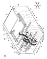
- the banknote deposit / withdrawal unit 10 incorporates a shutter opening / closing mechanism 16 that opens and closes the shutter 24 and a shutter locking / unlocking mechanism 18 that locks the shutter 24 to lock or unlock it.
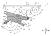
- the shutter opening / closing mechanism 16 mainly includes a post two-stage gear 32, an idling gear 38, a lock gear 48, a drive gear 54, and a pinion gear 58.
- the shutter locking / unlocking mechanism 18 mainly includes a post second gear 32, a second gear 34, a cam gear 42, a lock portion 64, and a lock gear 48.
- a shutter rack 26 is formed in which grooves cut in the left-right direction are arranged in the front-rear direction from the front end to the rear end of the shutter 24.
- a motor 28 that generates a driving force clockwise and counterclockwise in a side view is attached to the frame 20 behind the shutter 24.
- a motor gear 30 having a cylindrical shape is attached to the left end of the motor 28 so as to rotate in accordance with the rotation of the motor 28 in a side view.
- a post two-stage gear 32 is attached to the frame 20 so as to be rotatable about the post two-stage gear shaft 36 in a side view so as to mesh with the motor gear 30.
- the post two-stage gear 32 is formed on the left side of the large-diameter post two-stage gear portion 32A having a cylindrical shape and gear teeth formed on the outer peripheral surface thereof.
- the small-diameter post two-stage gear portion 32B has a cylindrical shape smaller in diameter than the large-diameter post two-stage gear portion 32A and has gear teeth formed on the outer peripheral surface.
- a cylindrical post part 32C projects from the left side surface of the small-diameter post two-stage gear part 32B toward the left side.
- the post two-stage gear 32 receives the rotational driving force from the motor 28 when the large-diameter post two-stage gear portion 32A meshes with the motor gear 30.
- the post two-stage gear 32 has a small-diameter post two-stage gear section 32B having a smaller diameter than the large-diameter post two-stage gear section 32A, so that a two-stage gear 34 (described later) meshed with the small-diameter post two-stage gear section 32B. ),
- the rotational drive force from the motor 28 is decelerated and transmitted.
- the diameter of a gear having gear teeth formed on the outer peripheral surface is also referred to as a gear diameter.
- an idling gear 38 that is rotatable about the same post two-stage gear shaft 36 as the post two-stage gear 32 is provided.
- the idling gear 38 is formed on the left side of the large-diameter portion 38A having a cylindrical shape and a diameter smaller than that of the large-diameter portion 38A. It is comprised from the idle gear part 38B in which the tooth
- an arc-shaped long hole portion 38C is recessed in a circular arc shape around the half circumference around the post two-stage gear shaft 36.
- the post portion 32C is slidably fitted.
- a contact end surface 38CB at the time of closing in the clockwise direction in the side view and a contact end surface 38CA at the time of opening in the counterclockwise direction of the rotation direction are formed.
- the banknote deposit / withdrawal unit 10 delays the timing at which the rotation from the motor 28 is transmitted to the pinion gear 58 by the post two-stage gear 32 and the idling gear 38 (details will be described later).
- the two-stage gear 34 is attached to the frame 20 so as to be rotatable about the two-stage gear shaft 40 in a side view so as to mesh with the post two-stage gear 32.
- the two-stage gear 34 is formed on the left side of the large-diameter two-stage gear section 34A and the large-diameter two-stage gear section 34A. Also, it is composed of a small-diameter two-stage gear portion 34B having a cylindrical shape with a small gear diameter and gear teeth formed on the outer peripheral surface.
- Rotational driving force from the motor 28 is transmitted to the two-stage gear 34 when the large-diameter two-stage gear section 34A meshes with the small-diameter post two-stage gear section 32B of the post two-stage gear 32.
- the two-stage gear 34 has a small-diameter two-stage gear section 34B having a smaller gear diameter than the large-diameter two-stage gear section 34A, whereby a motor is transferred to a cam gear 42 (described later) that meshes with the small-diameter two-stage gear section 34B.
- the rotational driving force from 28 is decelerated and transmitted.
- the two-stage gear 34 decelerates the rotation from the post two-stage gear 32 and converts the rotation of the cam gear 42 relative to one opening / closing of the shutter 24 to less than one revolution.
- the bill depositing / dispensing unit 10 includes various gears of the shutter opening / closing mechanism 16 and the shutter locking / unlocking mechanism 18 according to a gear ratio in which the cam gear 42 rotates almost once when the shutter 24 moves from the open state to the closed state. Yes.
- the cam gear 42 is attached to the frame 20 so as to be rotatable about the cam gear shaft 41 in a side view so as to mesh with the two-stage gear 34.
- the cam gear 42 has a cam gear portion 43 having a cylindrical shape and gear teeth formed on the outer peripheral surface.
- the cam gear 42 receives the rotational driving force from the motor 28 when the cam gear portion 43 meshes with the small-diameter two-stage gear portion 34B of the two-stage gear 34.
- a groove is formed on the outer peripheral surface of the outer peripheral wall of the outer peripheral wall standing in the left direction along the outer periphery of the disc-shaped bottom surface 43 ⁇ / b> A.
- An operating portion 44 is formed.
- a disk-shaped cam unit 45 is erected in the left direction from the bottom surface 43A.
- the cam portion 45 is formed with a release link sliding portion 46 in which approximately one quarter of the substantially circular shape is recessed toward the cam gear shaft 41.
- a reverse rotation prevention end face 46A which is a flat surface from the outer peripheral surface of the cam portion 45 toward the cam gear shaft 41, is formed on the distal end side in the counterclockwise rotation direction of the release link sliding portion 46.
- a projection portion 44 ⁇ / b> A that protrudes toward the cam gear shaft 41 is formed at a location facing the reverse rotation prevention end surface 46 ⁇ / b> A of the cam portion 45.
- a cylindrical lock gear 48 is provided at the front upper portion of the idle gear 38 (FIG. 3) so as to be rotatable about the lock gear shaft 52 in a side view so as to mesh with the idle gear 38.
- the left and right ends of the lock gear shaft 52 are fixed to the frame 20.
- the lock gear 48 includes a lock gear portion 49 having a cylindrical shape and gear teeth formed on the outer peripheral surface, and a lock engaging portion 50 formed on a side surface portion of the lock gear portion 49. It is configured.
- Rotational driving force from the motor 28 is transmitted to the lock gear 48 when the lock gear portion 49 meshes with the idling gear portion 38B of the idling gear 38.
- the lock latching portion 50 is provided with a lock latching sliding portion 51 in which almost a quarter of the circumference is cut out in an arc shape.
- a lock end surface 51 ⁇ / b> A that is a plane from the outer peripheral surface of the lock locking portion 50 toward the rotation center of the lock gear shaft 52 is formed on the front end side in the counterclockwise rotation direction of the lock locking sliding portion 51. .
- the front upper part of the lock gear 48 has a cylindrical shape and gear teeth are formed on the outer peripheral surface, and a drive gear 54 whose gear diameter is smaller than the lock gear part 49 of the lock gear 48 is engaged with the lock gear 48.
- the drive gear shaft 56 is inserted and fixed, and is provided so as to rotate together with the drive gear shaft 56 in a side view.
- the left and right ends of the drive gear shaft 56 are fixed to the frame 20 so as to be rotatable.
- the drive gear 54 is engaged with the lock gear portion 49 of the lock gear 48 to transmit the rotational driving force from the motor 28.
- Pinion gears 58 having a cylindrical shape and gear teeth formed on the outer peripheral surface and having a slightly larger gear diameter than the drive gear 54 are fixed to the left and right ends of the drive gear shaft 56 so as to match the phases of the gear teeth. ing.
- the pinion gear 58 meshes with the shutter rack 26 in the upper shutter 24 to convert the rotational driving force of the pinion gear 58 into a linear motion in the front-rear direction of the shutter 24 and transmit it.
- An open detection sensor 60 and a close detection sensor 62 fixed to the frame 20 are provided below the vicinity of the rear end of the shutter 24.
- the open detection sensor 60 detects the open state by detecting the presence or absence of an unillustrated shielding portion provided on the shutter 24 in a state where the shutter 24 is fully open.
- the closing detection sensor 62 detects the closed state by detecting the presence or absence of a non-illustrated shielding portion provided on the shutter 24 when the shutter 24 is closed.
- a lock portion 64 is provided on the left side of the cam gear 42 and the lock gear 48.
- the lock portion 64 is inserted into a cylindrical rotation fulcrum shaft 67 through a shaft hole 64D drilled at the rear end of the upper portion, so that the rotation fulcrum shaft 67 serves as a fulcrum in the clockwise and counterclockwise direction. Rotate clockwise.
- a lock engaging projection 64A is formed at the front end of the lock 64.
- the lock engaging protrusion 64A is cylindrical and is provided with a lock rotating member 65 such as a rotatable roller or a bearing.
- the lock rotating member 65 enters the lock engaging sliding part 51 of the lock gear 48. Rotates while in contact.
- a lock release link portion 64B is formed at the rear end of the lower portion of the lock portion 64.
- the unlocking link portion 64B is substantially cylindrical and is provided with an unlocking rotation member 66 such as a rotatable roller or bearing, and the unlocking rotation member 66 enters the release link sliding portion 46 of the cam gear 42. Rotates while in contact.
- a shield part 64 ⁇ / b> C protruding forward is formed at the front end of the lower part of the lock part 64.
- a lock state detection sensor 70 fixed to the frame 20 is provided in the vicinity of the shielding portion 64C of the lock portion 64.
- the lock state detection sensor 70 detects the lock state by detecting whether or not the shielding part 64C of the lock part 64 has shielded the detection part.
- a winding portion 68C that is a central portion in the front-rear direction of one metal rod of a spring 68 that is a torsion bar spring is wound. .
- a forearm portion 68F which is a part of the torsion bar spring, extends in the front direction, and a rear arm portion 68R extends in the rear direction.
- the spring 68 is a spring hole portion 64E formed between the shaft hole portion 64D and the lock engaging projection portion 64A in the lock portion 64 in a state where the front end portion of the forearm portion 68F is positioned below the natural state. And the rear end portion of the rear arm portion 68R is fixed to the frame 20 in a state of being positioned below the natural state.
- the lock portion 64 is biased by the spring 68 so as to rotate counterclockwise in a side view.
- the motor gear 30, the second gear 34, the cam gear 42, the post second gear 32, the idling gear 38, the lock gear 48, the drive gear 54, and the pinion gear 58 are in the closed lock amount.
- the gear teeth are arranged in phase with each other.
- the drive gear 54, the drive gear shaft 56, and the pinion gear 58 which are mechanisms for moving the shutter 24 in the opening direction and the closing direction, are collectively referred to as an opening / closing portion 94, and the motor 28, the motor gear, which is a mechanism having a rotational driving force.
- the post two-stage gear 32, the idling gear 38, and the two-stage gear 34 are collectively referred to as a driving unit 96, and the driving force of the driving unit 96 is changed by contacting and rotating the driving unit 96 and the opening / closing unit 94.
- the cam gear 42 and the lock portion 64 that transmit to each other are collectively referred to as a shutter locking / unlocking portion 98.
- the post portion 32C of the post two-stage gear 32 is in contact with the contact end surface 38CB when the arcuate elongated hole portion 38C of the idle gear 38 is closed.
- lock engaging protrusion 64A of the lock part 64 is in contact with the lock end surface 51A of the lock engaging sliding part 51 of the lock gear 48.
- lock release link portion 64B of the lock portion 64 is not in contact with the reverse rotation prevention end face 46A of the cam portion 45 of the cam gear 42 and is slightly separated.
- the reverse rotation prevention end surface 46A of the cam portion 45 is located in the vicinity of the front end side in the counterclockwise rotation direction with respect to the lock release link portion 64B of the lock portion 64. Therefore, the reverse rotation preventing end face 46A can prevent the cam gear 42 from rotating clockwise in the closed state.
- the lock gear 48 is prevented from rotating clockwise (rotation in the direction in which the shutter 24 is opened) by the lock end surface 51A coming into contact with the lock engaging protrusion 64A of the lock portion 64.
- the lock unit 64 restricts the clockwise rotation of the lock gear 48, so that the banknote deposit / withdrawal unit 10 can prevent the shutter 24 from being opened.
- the lock engaging protrusion 64A of the lock part 64 is lowered from the lock end surface 51A. It moves in the direction and retracts from the lock latching sliding part 51, and the lock may be released in the locked state.
- the lock unit 64 cannot be rotated clockwise in FIG. There is a possibility that.
- the banknote depositing / withdrawing unit 10 prevents the shutter 24 from being opened in the closed state and prevents the shutter 24 from being opened, by setting the angle between the virtual line VL1 and the virtual line VL2 to 90 degrees.
- opening the shutter 24 it is possible to shift to a lock-free state described later.
- cam diameter CR The distance from the cam gear shaft 41 (hereinafter also referred to as cam diameter CR) is increased.
- the lock engaging protrusion 64A of the lock part 64 moves downward from the lock end surface 51A of the lock gear 48 and retracts from the lock engaging sliding part 51.
- the banknote deposit / withdrawal portion 10 detects a lock-free state in which the lock is released.
- the protrusion 44A of the cam gear 42 is located in the vicinity of the distal end side in the clockwise rotation direction with respect to the lock release link 64B of the lock 64. For this reason, the protrusion 44 ⁇ / b> A can prevent the lock release link part 64 ⁇ / b> B from entering the release link sliding part 46 when transitioning from the closed state to the open state.
- the bill depositing / dispensing unit 10 prevents the cam gear 42 from rotating more than once, and the two-stage gear 34, the cam gear 42, the post two-stage gear 32, the idle gear 38, the lock gear 48, the drive gear 54, and the pinion gear 58.
- the gear teeth can be kept out of phase.
- the banknote deposit / withdrawal unit 10 rotates the motor 28 counterclockwise based on the control of the control unit. This rotational driving force is sequentially transmitted, the post second gear 32 rotates clockwise, the second gear 34 rotates counterclockwise, and the cam gear 42 rotates clockwise.
- the lock portion 64 rolls the lock release link portion 64B along the outer peripheral surface of the cam portion 45 of the cam gear 42 while the cam diameter CR is constant, so that the lock engaging projection portion 64A locks the lock gear 48.
- the state retracted from the locking sliding portion 51 is maintained.
- the motor 28 continues to rotate counterclockwise until the lock release link portion 64B of the lock portion 64 is positioned at the boundary between the outer peripheral surface of the cam portion 45 and the release link sliding portion 46 (that is, the cam diameter CR is reduced).
- the cam gear 42 rotates clockwise until it begins to decrease.
- the lock part 64 rolls the lock locking projection part 64 ⁇ / b> A along the outer peripheral surface of the lock locking part 50 of the lock gear 48, so that the lock locking projection part 64 ⁇ / b> A is locked to the lock locking slide of the lock gear 48.
- the state retracted from the moving part 51 is maintained.
- the banknote depositing / dispensing unit 10 detects the lock-free state because the shielding unit 64C of the lock unit 64 is still located behind and below the lock state detection sensor 70.
- the lock engaging protrusion 64A of the lock portion 64 is in contact with the lock end surface 51A of the lock engaging slide portion 51 of the lock gear 48 that rotates counterclockwise. It rolls and enters the lock locking sliding part 51.
- the lock portion 64 is rotated counterclockwise by the urging force of the spring 68 around the rotation fulcrum shaft 67.
- the unlocking link portion 64B is located slightly separated from the reverse rotation preventing end surface 46A of the cam portion 45 of the cam gear 42.
- the banknote depositing / dispensing unit 10 detects the locked state by moving the shielding unit 64C of the locking unit 64 to the front upper side so as to block the locked state detection sensor 70.
- the banknote depositing / dispensing unit 10 transmits driving force from the motor 28 which is the same driving source to the shutter opening / closing mechanism 16 and the shutter locking / unlocking mechanism 18 to open and close the shutter 24 and lock the shutter 24. And unlocking.
- the banknote deposit / withdrawal unit 10 does not directly contact and lock the shutter 24, but applies rotational driving force to the drive gear 54, the drive gear shaft 56, and the pinion gear 58 that drive the opening / closing of the shutter 24.
- the shutter 24 is locked by restricting the rotation of the lock gear 48 to be transmitted by the lock portion 64.
- the banknote deposit / withdrawal unit 10 has a lock latching position PL (a contact point between the lock unit 64 and the lock gear 48) for locking the shutter 24 at the banknote deposit / withdrawal unit 210 (FIG. 9). It can be separated from the outlet 6 and the shutter 24.
- the banknote depositing / withdrawing unit 10 can make it difficult to insert a tool from the outside between the shutter 24 and the frame 20 to access the lock locking position PL, thereby making it difficult to unlock from the outside. Action can be prevented.
- the bill depositing / dispensing unit 10 is provided with the operation unit 44 in the cam gear 42 so that the operator rotates the cam gear 42 while touching the operation unit 44 during maintenance work, and manually unlocks and locks the shutter 24. Can do.
- the banknote deposit / withdrawal unit 10 moves the shutter 24 in the opening direction for opening the banknote storage unit 22 for storing banknotes taken from outside via the banknote slot 6 and the closing direction for closing from the outside.
- the opening / closing portion 94, the driving portion 96 having driving force, and the driving force of the driving portion 96 is transmitted to the opening / closing portion 94 by rotating in contact with the driving portion 96 and the opening / closing portion 94, thereby driving the opening / closing portion 94.
- the lock gear 48 as a gear portion to be operated and the rotation of the gear portion in contact with the gear portion are restricted, thereby restricting the operation of the opening / closing portion 94 and locking the shutter 24 so that the shutter 24 does not move.
- a shutter locking / unlocking portion 98 for releasing the lock so as to move the opening / closing portion 94 and move the shutter 24 is provided.
- the banknote depositing / withdrawing unit 10 does not contact and lock the shutter 24 itself, but locks it by contacting and locking the lock gear 48 that drives the pinion gear 58 that opens and closes the shutter 24.
- the position PL can be separated from the shutter 24 to make it difficult to unlock from the outside.
- the automatic teller machine 1 according to the second embodiment has banknotes as shown in FIG.
- the deposit / withdrawal unit 110 is different from the banknote deposit / withdrawal unit 10, but the other configuration is the same.
- the banknote deposit / withdrawal unit 110 is different from the banknote deposit / withdrawal unit 10 in that the opening / closing unit 194 is different from the opening / closing unit 94.
- the opening / closing part 194 includes a drive gear 54, a drive gear shaft 74, a drive pulley 78, a belt 76, and a driven pulley 80.
- a drive gear 54 having a cylindrical shape and gear teeth formed on the outer peripheral surface thereof is inserted into the drive gear shaft 74 in a side view so as to mesh with the lock gear 48 at the front upper portion of the lock gear 48 in the banknote deposit / withdrawal unit 110. And fixed so as to rotate together with the drive gear shaft 74.
- the left and right ends of the drive gear shaft 74 are fixed to the frame 20 so as to be rotatable.
- the drive gear 54 is engaged with the lock gear portion 49 of the lock gear 48 to transmit the rotational driving force from the motor 28.
- drive pulleys 78 having a cylindrical shape and belt teeth formed on the outer peripheral surface are fixed to the drive gear shaft 74 so as to match the phases of the belt teeth.
- a driven pulley 80 having a cylindrical shape and belt teeth formed on the outer peripheral surface is provided in front of the drive pulley 78 so as to be rotatable around a shaft (not shown) extending in the left-right direction.
- a belt 76 made of an endless belt is formed, in which belt teeth that mesh with the belt teeth of the drive pulley 78 and the belt teeth of the driven pulley 80 are formed on the inner peripheral surface.
- a shutter link portion 82 that protrudes downward is formed at the left and right rear ends of the shutter 124, and the shutter link portion 82 is fixed to a predetermined position in the upper half of the belt 76.
- cylindrical guide rollers 84 are provided so as to protrude from the left and right side surfaces of the front end portion of the shutter 124 in the left direction and the right direction, respectively.
- Slide guides 86 having grooves along the front-rear direction are fixed to the frame 20 on both the left and right sides of the shutter 124. In FIG. 8, the slide guide 86 is partially omitted.
- the shutter 124 is configured to be movable in the front-rear direction along the slide guide 86 when the guide roller 84 is slidably fitted into the groove portion of the slide guide 86.
- the driving force by this rotation is transmitted to the post second gear 32, the second gear 34, and the cam gear 42 in the same manner as the bill deposit / withdrawal unit 10, so that the bill deposit / withdrawal unit 110 is in a lock-free state.
- this driving force is transmitted by sequentially transmitting the post two-stage gear 32, the idling gear 38, the lock gear 48, the drive gear 54, and the drive gear shaft 74. Then, the drive pulley 78 is rotated counterclockwise.
- the banknote deposit / withdrawal unit 110 rotates the motor 28 counterclockwise in a side view based on the control of the control unit.
- the driving force by this rotation sequentially transmits the post two-stage gear 32, the idling gear 38, the lock gear 48, the drive gear 54, and the drive gear shaft 74, thereby rotating the drive pulley 78 clockwise.
- the driving force of the motor 28 sequentially transmits the post second gear 32, the second gear 34, and the cam gear 42 in the same manner as the bill deposit / withdrawal unit 10, whereby the bill deposit / withdrawal unit 110 is locked.
- the banknote depositing / dispensing unit 110 rotates the belt 76 by rotating the drive pulley 78 and the driven pulley 80 using the rotational driving force from the motor 28, and opens and closes the shutter 124 fixed to the belt 76. I tried to make it.
- the banknote deposit / withdrawal unit 110 not only uses the shutter rack 26 of the shutter 24 to open and close the shutter 24 like the banknote deposit / withdrawal unit 10, but also uses the belt 76, the drive pulley 78, and the driven pulley 80. Also in the mechanism for opening and closing 124, it is difficult to insert a tool from the outside between the shutter 124 and the frame 20 to gain access to the lock locking position PL, making it difficult to unlock from the outside, and unauthorized unlocking action Can be prevented.
- the driving force is transmitted from the motor 28 which is the same driving source to the shutter opening / closing mechanism 16 and the shutter locking / unlocking mechanism 18, and the shutter 24 is opened and closed. The case of unlocking was described.
- the present invention is not limited to this, and a motor that transmits driving force to the shutter opening / closing mechanism 16 and a motor that transmits driving force to the shutter locking / unlocking mechanism 18 may be provided separately.
- the post second gear 32, the second gear 34 and the idling gear 38 are omitted, the motor gear 30 is brought into contact with the lock gear 48, and the cam gear shaft 41 of the cam gear 42 is rotated by a motor different from the motor 28. .
- the rotation of the motor that drives the lock gear 48 of the shutter opening / closing mechanism 16 is started after a predetermined time has elapsed since the rotation of the motor that drives the cam gear 42 of the shutter locking / unlocking mechanism 18 is started.
- the shutter may be opened after the lock is released.
- the rotational driving force of the motor 28 is transmitted to the cam gear 42 via the motor gear 30, the post two-stage gear 32, and the two-stage gear 34.
- the present invention is not limited to this, and the cam gear 42 is brought into contact with the motor gear 30 or the post two-stage gear 32, and the rotational driving force of the motor 28 is transmitted from the motor gear 30 or the post two-stage gear 32 to the cam gear 42. good.
- the shutter 24 is arranged so as to cover the banknote inlet / outlet 6 from the lower side of the banknote inlet / outlet 6 (inside the frame 20) has been described.
- the present invention is not limited to this, and a shutter may be disposed so as to cover the banknote entrance / exit 6 from the upper side of the banknote entrance / exit 6 (outside of the frame 20), and the outside of the frame 20 may be slid.
- the present invention is not limited to this, and the shutter may be curved. In short, any shape corresponding to the shape of the bill insertion / exit 6 of the bill deposit / withdrawal unit 10 may be used.
- the drive gear 54, the drive gear shaft 56, and the pinion gear 58 are omitted, and the lock gear 48 of the lock gear 48 is engaged with the shutter rack 26 of the shutter 24 to make the shutter 24. It can be opened and closed.
- the lock gear 48 is rotated.
- the present invention is not limited to this, and the lock gear 48 may be reciprocated in the front-rear direction.
- the lock gear 48 is moved so as to transmit the rotation from the idle gear 38 to the shutter 24, and when the lock is applied, the lock portion 64 is moved. It is only necessary that the movement is restricted by being locked.
- the gear diameter of the lock gear portion 49 of the lock gear 48 is made smaller than the gear diameter of the drive gear 54, and the gear ratio of the lock gear 48 to the drive gear 54 is reduced, thereby closing the closed state.
- the shutter 24 may be made difficult to open. In this case, the force with which the lock portion 64 holds the lock gear 48 can be reduced.
- the present invention when applying this invention to the banknote depositing / withdrawing part 10 of the cash automatic transaction apparatus 1 which deposits a banknote according to the transaction content with a user, and also withdraws a banknote to a user. Said.
- the present invention is not limited to this, and the present invention may be applied to various devices such as a banknote depositing section dedicated to depositing banknotes and a banknote dispensing section dedicated to dispensing banknotes.
- coin deposit / withdrawal unit that deposits coins according to the transaction details with the user and dispenses coins to the user, but also a coin deposit / department unit dedicated to depositing coins, and a deposit / withdrawal coin. You may apply this invention with respect to various apparatuses, such as a coin withdrawal part only for money.
- any device may be used as long as it opens and closes the shutter that moves in the opening direction for opening the medium accommodating portion for accommodating the medium to the outside and the closing direction for closing the medium from the outside, and locks and unlocks the shutter.
- cash such as a banknote
- the banknote depositing / withdrawing parts 10 and 110 of the cash automatic transaction apparatus 1 which withdraws cash to a user are booked.
- the present invention is not limited to this, and can be applied to various apparatuses having a mechanism for inputting and discharging a paper-like medium.
- the bill is described as the medium.
- the present invention is not limited to this, and may be a thin paper medium such as a gift certificate, a cash voucher, an admission ticket or the like.
- the present invention is not limited to the first embodiment, the second embodiment, and other embodiments described above. That is, the scope of application of the present invention extends to an embodiment in which a part or all of the above-described embodiment and another embodiment are arbitrarily combined, and an embodiment in which a part is extracted.
- the opening / closing part 94 or 194 as the opening / closing part, the driving part 96 as the driving part, the lock gear 48 as the gear part, and the shutter locking / unlocking part 98 as the shutter locking / unlocking part The case where the bill depositing / dispensing part 10 or 110 as the shutter device is configured is described.
- a shutter device may be configured by an opening / closing unit, a driving unit, a gear unit, and a shutter locking / unlocking unit having various other configurations.
- the customer service section 9 as a reception section, the opening / closing section 94 or 194 as an opening / closing section, the driving section 96 as a driving section, the lock gear 48 as a gear section, and the shutter locking / unlocking
- the cash automatic transaction apparatus 1 as a medium transaction apparatus is configured by the shutter locking / unlocking section 98 as a section and the conveyance path 15 as a conveyance section has been described.
- a medium transaction apparatus may be configured by a receiving unit, an opening / closing unit, a driving unit, a gear unit, a shutter locking / unlocking unit, and a conveying unit having various other configurations.
- the present invention can be used in a banknote depositing / withdrawing unit or the like that is provided in an automatic teller machine or the like and into which banknotes to be deposited by a user are inserted and banknotes to be dispensed to the user are discharged.
Landscapes
- Physics & Mathematics (AREA)
- General Physics & Mathematics (AREA)
- Financial Or Insurance-Related Operations Such As Payment And Settlement (AREA)
- Feeding And Guiding Record Carriers (AREA)
- Transmission Devices (AREA)
- Pile Receivers (AREA)
- Control Of Vending Devices And Auxiliary Devices For Vending Devices (AREA)
Abstract
Description
[1-1.現金自動取引装置の全体構成]
図1に外観を示すように、現金自動取引装置1は、箱状の筐体19を中心に構成されており、例えば金融機関等に設置され、利用者との間で入金取引や出金取引等の現金に関する取引を行うようにされている。
図2に示すように紙幣入出金機4は、入金された紙幣を出金にも利用する所謂リサイクル型の紙幣入出金機であり、その上部に紙幣入出金部10、鑑別部11及び一時保留部12が配置され、その下部に複数の紙幣収納庫13とリジェクト庫14とが配置された構成となっている。
図3に外観を示すように、紙幣入出金部10は、箱状のフレーム20を中心に構成されており、当該フレーム20の上方の前部分には、紙幣入出口6が穿設されている。
[1-4-1.閉鎖状態におけるロック状態]
以上の構成において、図5に示すように、閉鎖状態のロック状態においては、ロック部64の遮蔽部64Cがロック状態検知センサ70を遮るよう位置することにより、紙幣入出金部10はロック状態を検知する。
閉鎖状態におけるロック状態からシャッタ24を開放させる際、図6に示すように紙幣入出金部10は制御部の制御に基づきモータ28を時計回りに回転させる。この回転駆動力が順次伝達され、ポスト2段ギア32は反時計回りに、2段ギア34は時計回りにそれぞれ回転し、カムギア42は反時計回りに回転する。
図6に示した閉鎖状態のロックフリー状態から、モータ28がさらに時計回りに回転することによりポスト2段ギア32が反時計回りに回転すると、当該ポスト2段ギア32におけるポスト部32Cが、空転ギア38の円弧状長穴部38Cに沿って移動して開放時当接端面38CAに当接する。
開放状態においては、ロック部64のロック係止突起部64Aがロックギア48のロック端面51Aよりも下側に位置することによりロック係止部50から退避し、紙幣入出金部10はロックフリー状態となっている。
以上の構成において、紙幣入出金部10は、シャッタ24に直接接触してロックするのではなく、シャッタ24の開閉駆動を行うドライブギア54、ドライブギアシャフト56及びピニオンギア58に対し回転駆動力を伝達するロックギア48の回転をロック部64で規制することにより、シャッタ24をロックするようにした。
第2の実施の形態による現金自動取引装置1は、第1の実施の形態による現金自動取引装置1と比べて、図3との対応部分に同一符号を付した図8に示すように、紙幣入出金部110が紙幣入出金部10と異なっているものの、それ以外は同様に構成されている。
紙幣入出金部110は、紙幣入出金部10と比べて、開閉部194が開閉部94と異なっている。開閉部194は、ドライブギア54、ドライブギアシャフト74、ドライブプーリ78、ベルト76及び従動プーリ80により構成されている。
以上の構成において、閉鎖状態(ロック状態)からシャッタ124を開放させる際、紙幣入出金部110は、制御部の制御に基づきモータ28を側面視時計回りに回転させる。
なお上述した実施の形態においては、同一の駆動源であるモータ28から、シャッタ開閉機構16及びシャッタ施解錠機構18に駆動力を伝達し、シャッタ24を開け閉めすると共に、当該シャッタ24の施錠及び解錠を行う場合について述べた。
Claims (11)
- 開口を介し外部から取り込んだ媒体を収容する媒体収容部を外部に開放する開放方向及び外部から閉鎖する閉鎖方向にシャッタを移動させる開閉部と、
駆動力を有する駆動部と、
前記駆動部及び前記開閉部に接触して回転することで前記駆動部の駆動力を前記開閉部に伝達することにより、前記開閉部を駆動するギア部と、
前記ギア部に接触し回転を規制することにより、前記開閉部の動作を規制して閉鎖状態にある前記シャッタをロックする一方、前記ギア部から外れることにより、前記開閉部を動作可能にして前記シャッタのロックを解除するシャッタ施解錠部と
を有するシャッタ装置。 - 前記シャッタ施解錠部は、前記駆動部からの駆動力が伝達されることにより、前記ギア部に接触するか又は外れるよう移動する
請求項1のシャッタ装置。 - 前記シャッタ施解錠部は、
前記駆動部から駆動力を伝達され回転するカムギアと、
一部が前記カムギアに接触し他の一部が前記ギア部に係止することにより前記ギア部の回転を規制する一方、前記カムギアの回転に応じて回動し前記ギア部から前記他の一部が外れることにより前記ギア部を回転可能にさせるロック部と
を有する請求項2のシャッタ装置。 - 前記ギア部は、略円筒形状でなり外周面の一部が凹設されたロック係止部を有するロックギアを有し、
前記ロック部は、転動するロック回転部材が前記ロックギアにおける前記ロック係止部に係止することにより、前記ロックギアの回転を規制する
請求項3のシャッタ装置。 - 前記カムギアは、略円形でなり外周面の一部が内周に向かって凹設された解除リンク摺動部が形成されたカム部を有し、
前記ロック部は、前記解除リンク摺動部に接触し転動可能なロック解除回転部材が、前記カムギアの回転に伴い前記カム部の外周面へ移動することにより回動し、前記ロック回転部材が前記ロックギアにおける前記ロック係止部から外れることにより、前記ロックギアを回転可能にする
請求項4のシャッタ装置。 - 前記駆動部は、回転可能な複数のギアを有し、前記シャッタが開放状態から閉鎖状態まで移動する際、前記カムギアがほぼ1回転するギア比で構成されている
請求項5のシャッタ装置。 - 前記シャッタにおいて前記開閉部と対向する箇所にはラックが形成され、
前記開閉部は、外周面にギア歯が形成されたピニオンギアを有し、前記シャッタの前記ラックに噛合して回転することにより、前記シャッタを移動させる
請求項3のシャッタ装置。 - 前記開閉部は、回転可能な複数のプーリと、前記シャッタの移動方向に沿って延設するよう当該プーリに架設され前記シャッタが固定された無端ベルトとを有し、当該プーリの回転に伴って当該無端ベルトが回転することにより、前記シャッタを移動させる
請求項3のシャッタ装置。 - 前記カムギアには、当該カムギアを手動で回転させる操作部が形成されている
請求項3のシャッタ装置。 - 前記シャッタ施解錠部は、前記駆動部からの駆動力が伝達されず、前記駆動部において駆動力を発生する駆動源とは別の、前記シャッタ施解錠部を駆動する施解錠駆動部から駆動力を伝達される
請求項1のシャッタ装置。 - 紙葉状の媒体に関する取引を受け付ける受付部と、
開口を介し外部から取り込んだ媒体を収容する媒体収容部を外部に開放する開放方向及び外部から閉鎖する閉鎖方向にシャッタを移動させる開閉部と、
駆動力を有する駆動部と、
前記駆動部及び前記開閉部に接触して回転することで前記駆動部の駆動力を前記開閉部に伝達することにより、前記開閉部を駆動するギア部と、
前記ギア部に接触し回転を規制することにより、前記開閉部の動作を規制して閉鎖状態にある前記シャッタをロックする一方、前記ギア部から外れることにより、前記開閉部を動作可能にして前記シャッタのロックを解除するシャッタ施解錠部と、
前記受付部により受け付け前記媒体収容部に収容された前記媒体を搬送する搬送部と
を有する媒体取引装置。
Priority Applications (3)
| Application Number | Priority Date | Filing Date | Title |
|---|---|---|---|
| RU2015124039A RU2613862C2 (ru) | 2012-12-28 | 2013-11-11 | Устройство с заслонкой и устройство выполнения транзакций с носителями |
| CN201380066490.9A CN104871218B (zh) | 2012-12-28 | 2013-11-11 | 闸板装置和介质交易装置 |
| US14/654,097 US9472038B2 (en) | 2012-12-28 | 2013-11-11 | Shutter device and medium transaction device |
Applications Claiming Priority (2)
| Application Number | Priority Date | Filing Date | Title |
|---|---|---|---|
| JP2012-287864 | 2012-12-28 | ||
| JP2012287864A JP5971119B2 (ja) | 2012-12-28 | 2012-12-28 | シャッタ装置及び媒体取引装置 |
Publications (1)
| Publication Number | Publication Date |
|---|---|
| WO2014103535A1 true WO2014103535A1 (ja) | 2014-07-03 |
Family
ID=51020634
Family Applications (1)
| Application Number | Title | Priority Date | Filing Date |
|---|---|---|---|
| PCT/JP2013/080406 Ceased WO2014103535A1 (ja) | 2012-12-28 | 2013-11-11 | シャッタ装置及び媒体取引装置 |
Country Status (5)
| Country | Link |
|---|---|
| US (1) | US9472038B2 (ja) |
| JP (1) | JP5971119B2 (ja) |
| CN (1) | CN104871218B (ja) |
| RU (1) | RU2613862C2 (ja) |
| WO (1) | WO2014103535A1 (ja) |
Cited By (1)
| Publication number | Priority date | Publication date | Assignee | Title |
|---|---|---|---|---|
| CN107016779A (zh) * | 2017-04-28 | 2017-08-04 | 深圳怡化电脑股份有限公司 | 自助金属设备及其带自锁结构的出钞门结构和自锁方法 |
Families Citing this family (13)
| Publication number | Priority date | Publication date | Assignee | Title |
|---|---|---|---|---|
| DE102012112344B4 (de) * | 2012-12-14 | 2014-07-03 | Löwen Entertainment GmbH | Münzkasse für ein geldbetätigtes Gerät |
| US10319171B2 (en) * | 2014-03-28 | 2019-06-11 | Ncr Corporation | Media escape prevention for self-service terminal |
| JP6303921B2 (ja) * | 2014-08-25 | 2018-04-04 | 沖電気工業株式会社 | 媒体取引装置 |
| CN104851185B (zh) * | 2015-05-28 | 2017-06-23 | 广州广电运通金融电子股份有限公司 | 一种新型闸门装置 |
| US10769878B2 (en) * | 2015-06-14 | 2020-09-08 | Diebold Nixdorf, Incorporated | Fascia gate separable gear drive |
| CN105513197B (zh) * | 2015-12-25 | 2017-11-17 | 河北汇金机电股份有限公司 | 一种防盗信封装钞装置 |
| CN106296985A (zh) * | 2016-08-05 | 2017-01-04 | 深圳怡化电脑股份有限公司 | 一种出钞门结构及银行自助终端 |
| CN107909712A (zh) * | 2017-12-18 | 2018-04-13 | 上海古鳌电子科技股份有限公司 | 一种存储仓活动门装置以及存取物体的方法 |
| US10726655B2 (en) * | 2018-04-27 | 2020-07-28 | Ncr Corporation | Shutter assembly for a self-service terminal |
| US10974096B2 (en) | 2018-10-24 | 2021-04-13 | Louie Simmons | Hamstring exercise device and method of using same |
| JP6687094B2 (ja) * | 2018-12-04 | 2020-04-22 | 富士電機株式会社 | 紙幣処理装置 |
| WO2021046535A1 (en) * | 2019-09-06 | 2021-03-11 | Crane Payment Innovations, Inc. | Banknote deposit-withdrawal system and architecture |
| CN113073927B (zh) * | 2021-03-29 | 2022-11-01 | 吕华军 | 一种金融设备闸门装置 |
Citations (7)
| Publication number | Priority date | Publication date | Assignee | Title |
|---|---|---|---|---|
| JPS62276686A (ja) * | 1986-05-26 | 1987-12-01 | オムロン株式会社 | 自動取引機のシヤツタ装置 |
| JPH04174097A (ja) * | 1990-07-26 | 1992-06-22 | Oki Electric Ind Co Ltd | 紙幣取り込み装置 |
| JPH07306969A (ja) * | 1994-05-13 | 1995-11-21 | Glory Ltd | 取引口のシャッタ装置 |
| JPH0991487A (ja) * | 1995-09-27 | 1997-04-04 | Oki Electric Ind Co Ltd | シャッタ開閉機構 |
| JPH10334305A (ja) * | 1997-05-30 | 1998-12-18 | Laurel Bank Mach Co Ltd | 硬貨入出金機 |
| WO2008111148A1 (ja) * | 2007-03-12 | 2008-09-18 | Glory Ltd. | シャッタ装置 |
| JP4641776B2 (ja) * | 2004-09-30 | 2011-03-02 | 沖電気工業株式会社 | シャッタ機構及び自動取引装置 |
Family Cites Families (17)
| Publication number | Priority date | Publication date | Assignee | Title |
|---|---|---|---|---|
| JPS63154537A (ja) * | 1986-12-19 | 1988-06-27 | Fujitsu Ltd | スタッカ |
| US5172643A (en) | 1990-07-16 | 1992-12-22 | Oki Electric Industry Co., Ltd. | Apparatus for handling strips of paper |
| JP3289866B2 (ja) * | 1994-07-01 | 2002-06-10 | 沖電気工業株式会社 | 紙幣自動入出金装置 |
| US20030173402A1 (en) * | 2000-06-15 | 2003-09-18 | Hiroshi Ogawa | Medium processing apparatus |
| JP4611502B2 (ja) * | 2000-09-19 | 2011-01-12 | サンデン株式会社 | 紙幣識別装置 |
| KR100425867B1 (ko) * | 2001-12-29 | 2004-04-01 | 엘지엔시스(주) | 현금자동 인출기의 고객 수취장치 |
| JP3815391B2 (ja) * | 2002-07-12 | 2006-08-30 | 松下電器産業株式会社 | 紙幣識別装置 |
| KR20060112461A (ko) * | 2005-04-27 | 2006-11-01 | 노틸러스효성 주식회사 | 금융자동화기기의 셔터 장치 |
| JP4832920B2 (ja) * | 2006-02-28 | 2011-12-07 | 富士通株式会社 | シャッタ開閉装置 |
| ES2719146T3 (es) * | 2006-06-23 | 2019-07-08 | Kba Notasys Sa | Dispositivo de numeración para numeración tipográfica que tiene detectores de calibración |
| JP5187157B2 (ja) * | 2008-11-24 | 2013-04-24 | 沖電気工業株式会社 | 自動取引装置及び自動取引装置の制御方法 |
| KR101001695B1 (ko) * | 2008-12-31 | 2010-12-15 | 노틸러스효성 주식회사 | 금융자동화기기의 셔터 개폐장치 |
| CN101872504B (zh) * | 2009-04-24 | 2013-01-23 | 山东新北洋信息技术股份有限公司 | 一种收纳装置 |
| CN102160094B (zh) * | 2009-06-30 | 2013-01-23 | 富士通先端科技株式会社 | 现金自动交易装置 |
| CN201673550U (zh) * | 2009-12-30 | 2010-12-15 | 北京神州金信科技股份有限公司 | 闸门控制装置 |
| CN102385771B (zh) * | 2010-08-30 | 2013-06-05 | 北京同方清芝商用机器有限公司 | 磁性挡块控制的二级闸门及使用该闸门的钱箱 |
| JP5640638B2 (ja) * | 2010-10-21 | 2014-12-17 | 沖電気工業株式会社 | シャッタ開閉機構および自動取引装置 |
-
2012
- 2012-12-28 JP JP2012287864A patent/JP5971119B2/ja not_active Expired - Fee Related
-
2013
- 2013-11-11 RU RU2015124039A patent/RU2613862C2/ru active
- 2013-11-11 US US14/654,097 patent/US9472038B2/en not_active Expired - Fee Related
- 2013-11-11 CN CN201380066490.9A patent/CN104871218B/zh not_active Expired - Fee Related
- 2013-11-11 WO PCT/JP2013/080406 patent/WO2014103535A1/ja not_active Ceased
Patent Citations (7)
| Publication number | Priority date | Publication date | Assignee | Title |
|---|---|---|---|---|
| JPS62276686A (ja) * | 1986-05-26 | 1987-12-01 | オムロン株式会社 | 自動取引機のシヤツタ装置 |
| JPH04174097A (ja) * | 1990-07-26 | 1992-06-22 | Oki Electric Ind Co Ltd | 紙幣取り込み装置 |
| JPH07306969A (ja) * | 1994-05-13 | 1995-11-21 | Glory Ltd | 取引口のシャッタ装置 |
| JPH0991487A (ja) * | 1995-09-27 | 1997-04-04 | Oki Electric Ind Co Ltd | シャッタ開閉機構 |
| JPH10334305A (ja) * | 1997-05-30 | 1998-12-18 | Laurel Bank Mach Co Ltd | 硬貨入出金機 |
| JP4641776B2 (ja) * | 2004-09-30 | 2011-03-02 | 沖電気工業株式会社 | シャッタ機構及び自動取引装置 |
| WO2008111148A1 (ja) * | 2007-03-12 | 2008-09-18 | Glory Ltd. | シャッタ装置 |
Cited By (1)
| Publication number | Priority date | Publication date | Assignee | Title |
|---|---|---|---|---|
| CN107016779A (zh) * | 2017-04-28 | 2017-08-04 | 深圳怡化电脑股份有限公司 | 自助金属设备及其带自锁结构的出钞门结构和自锁方法 |
Also Published As
| Publication number | Publication date |
|---|---|
| US20150317858A1 (en) | 2015-11-05 |
| JP2014130480A (ja) | 2014-07-10 |
| RU2015124039A (ru) | 2017-01-10 |
| RU2613862C2 (ru) | 2017-03-21 |
| JP5971119B2 (ja) | 2016-08-17 |
| CN104871218B (zh) | 2017-06-23 |
| US9472038B2 (en) | 2016-10-18 |
| CN104871218A (zh) | 2015-08-26 |
Similar Documents
| Publication | Publication Date | Title |
|---|---|---|
| JP5971119B2 (ja) | シャッタ装置及び媒体取引装置 | |
| US6098837A (en) | Note hopper/dispenser | |
| CN105900155B (zh) | 介质处理装置和介质交易装置 | |
| US9611117B2 (en) | Medium processing device and medium transaction device | |
| JP2003514292A (ja) | 紙幣を管理するための器械 | |
| EP2602772B1 (en) | Bills and/or card validator and storage apparatus | |
| JP5615391B2 (ja) | 紙葉還流庫 | |
| JP3600762B2 (ja) | 循環式貨幣処理装置 | |
| CN106710056A (zh) | 纸币处理装置 | |
| JP6834248B2 (ja) | 媒体処理装置及び媒体取引装置 | |
| JP7139722B2 (ja) | 紙葉類収容装置、紙葉類処理装置 | |
| JP6511764B2 (ja) | 媒体集積装置及び媒体取引装置 | |
| JP4311309B2 (ja) | 金銭処理装置、紙幣処理装置および硬貨処理装置 | |
| JP2002145462A (ja) | 紙幣処理装置 | |
| JP2000293732A (ja) | 紙幣処理装置 | |
| KR200374271Y1 (ko) | 금융 자동화기기의 이중셔터구조 | |
| JP2016212525A (ja) | 自動取引装置 | |
| WO2017221530A1 (ja) | 媒体処理装置及び媒体取引装置 | |
| JP6888394B2 (ja) | 媒体収納庫及び媒体取引装置 | |
| JP2613923B2 (ja) | シート搬送装置 | |
| JP6580941B2 (ja) | 自動釣銭入出金機の硬貨一括投入口カバーの開閉構造および自動釣銭入出金機 | |
| JP6206170B2 (ja) | 小束処理装置 | |
| JP2007334787A (ja) | 自動取引装置 | |
| JP2007206767A (ja) | 異物返却機構および自動取引装置 | |
| JP6268934B2 (ja) | 小束収納庫及び小束処理装置 |
Legal Events
| Date | Code | Title | Description |
|---|---|---|---|
| 121 | Ep: the epo has been informed by wipo that ep was designated in this application |
Ref document number: 13869292 Country of ref document: EP Kind code of ref document: A1 |
|
| ENP | Entry into the national phase |
Ref document number: 2015124039 Country of ref document: RU Kind code of ref document: A |
|
| WWE | Wipo information: entry into national phase |
Ref document number: 14654097 Country of ref document: US |
|
| NENP | Non-entry into the national phase |
Ref country code: DE |
|
| WWE | Wipo information: entry into national phase |
Ref document number: IDP00201503978 Country of ref document: ID |
|
| 122 | Ep: pct application non-entry in european phase |
Ref document number: 13869292 Country of ref document: EP Kind code of ref document: A1 |