WO2014069646A1 - 単純遊星減速装置 - Google Patents
単純遊星減速装置 Download PDFInfo
- Publication number
- WO2014069646A1 WO2014069646A1 PCT/JP2013/079794 JP2013079794W WO2014069646A1 WO 2014069646 A1 WO2014069646 A1 WO 2014069646A1 JP 2013079794 W JP2013079794 W JP 2013079794W WO 2014069646 A1 WO2014069646 A1 WO 2014069646A1
- Authority
- WO
- WIPO (PCT)
- Prior art keywords
- gear
- sun gear
- simple planetary
- carrier
- oil
- Prior art date
- Legal status (The legal status is an assumption and is not a legal conclusion. Google has not performed a legal analysis and makes no representation as to the accuracy of the status listed.)
- Ceased
Links
Images




Classifications
-
- F—MECHANICAL ENGINEERING; LIGHTING; HEATING; WEAPONS; BLASTING
- F16—ENGINEERING ELEMENTS AND UNITS; GENERAL MEASURES FOR PRODUCING AND MAINTAINING EFFECTIVE FUNCTIONING OF MACHINES OR INSTALLATIONS; THERMAL INSULATION IN GENERAL
- F16H—GEARING
- F16H1/00—Toothed gearings for conveying rotary motion
- F16H1/28—Toothed gearings for conveying rotary motion with gears having orbital motion
- F16H1/36—Toothed gearings for conveying rotary motion with gears having orbital motion with two central gears coupled by intermeshing orbital gears
-
- F—MECHANICAL ENGINEERING; LIGHTING; HEATING; WEAPONS; BLASTING
- F16—ENGINEERING ELEMENTS AND UNITS; GENERAL MEASURES FOR PRODUCING AND MAINTAINING EFFECTIVE FUNCTIONING OF MACHINES OR INSTALLATIONS; THERMAL INSULATION IN GENERAL
- F16H—GEARING
- F16H1/00—Toothed gearings for conveying rotary motion
- F16H1/28—Toothed gearings for conveying rotary motion with gears having orbital motion
-
- F—MECHANICAL ENGINEERING; LIGHTING; HEATING; WEAPONS; BLASTING
- F16—ENGINEERING ELEMENTS AND UNITS; GENERAL MEASURES FOR PRODUCING AND MAINTAINING EFFECTIVE FUNCTIONING OF MACHINES OR INSTALLATIONS; THERMAL INSULATION IN GENERAL
- F16H—GEARING
- F16H57/00—General details of gearing
- F16H57/08—General details of gearing of gearings with members having orbital motion
-
- E—FIXED CONSTRUCTIONS
- E02—HYDRAULIC ENGINEERING; FOUNDATIONS; SOIL SHIFTING
- E02F—DREDGING; SOIL-SHIFTING
- E02F9/00—Component parts of dredgers or soil-shifting machines, not restricted to one of the kinds covered by groups E02F3/00 - E02F7/00
- E02F9/08—Superstructures; Supports for superstructures
- E02F9/10—Supports for movable superstructures mounted on travelling or walking gears or on other superstructures
- E02F9/12—Slewing or traversing gears
-
- E—FIXED CONSTRUCTIONS
- E02—HYDRAULIC ENGINEERING; FOUNDATIONS; SOIL SHIFTING
- E02F—DREDGING; SOIL-SHIFTING
- E02F9/00—Component parts of dredgers or soil-shifting machines, not restricted to one of the kinds covered by groups E02F3/00 - E02F7/00
- E02F9/08—Superstructures; Supports for superstructures
- E02F9/10—Supports for movable superstructures mounted on travelling or walking gears or on other superstructures
- E02F9/12—Slewing or traversing gears
- E02F9/121—Turntables, i.e. structure rotatable about 360°
- E02F9/123—Drives or control devices specially adapted therefor
-
- E—FIXED CONSTRUCTIONS
- E02—HYDRAULIC ENGINEERING; FOUNDATIONS; SOIL SHIFTING
- E02F—DREDGING; SOIL-SHIFTING
- E02F9/00—Component parts of dredgers or soil-shifting machines, not restricted to one of the kinds covered by groups E02F3/00 - E02F7/00
- E02F9/08—Superstructures; Supports for superstructures
- E02F9/10—Supports for movable superstructures mounted on travelling or walking gears or on other superstructures
- E02F9/12—Slewing or traversing gears
- E02F9/121—Turntables, i.e. structure rotatable about 360°
- E02F9/128—Braking systems
-
- E—FIXED CONSTRUCTIONS
- E02—HYDRAULIC ENGINEERING; FOUNDATIONS; SOIL SHIFTING
- E02F—DREDGING; SOIL-SHIFTING
- E02F9/00—Component parts of dredgers or soil-shifting machines, not restricted to one of the kinds covered by groups E02F3/00 - E02F7/00
- E02F9/20—Drives; Control devices
- E02F9/202—Mechanical transmission, e.g. clutches, gears
-
- F—MECHANICAL ENGINEERING; LIGHTING; HEATING; WEAPONS; BLASTING
- F16—ENGINEERING ELEMENTS AND UNITS; GENERAL MEASURES FOR PRODUCING AND MAINTAINING EFFECTIVE FUNCTIONING OF MACHINES OR INSTALLATIONS; THERMAL INSULATION IN GENERAL
- F16H—GEARING
- F16H1/00—Toothed gearings for conveying rotary motion
- F16H1/28—Toothed gearings for conveying rotary motion with gears having orbital motion
- F16H1/34—Toothed gearings for conveying rotary motion with gears having orbital motion involving gears essentially having intermeshing elements other than involute or cycloidal teeth
-
- F—MECHANICAL ENGINEERING; LIGHTING; HEATING; WEAPONS; BLASTING
- F16—ENGINEERING ELEMENTS AND UNITS; GENERAL MEASURES FOR PRODUCING AND MAINTAINING EFFECTIVE FUNCTIONING OF MACHINES OR INSTALLATIONS; THERMAL INSULATION IN GENERAL
- F16H—GEARING
- F16H57/00—General details of gearing
- F16H57/04—Features relating to lubrication or cooling or heating
- F16H57/0409—Features relating to lubrication or cooling or heating characterised by increasing efficiency, e.g. by reducing splash losses
-
- F—MECHANICAL ENGINEERING; LIGHTING; HEATING; WEAPONS; BLASTING
- F16—ENGINEERING ELEMENTS AND UNITS; GENERAL MEASURES FOR PRODUCING AND MAINTAINING EFFECTIVE FUNCTIONING OF MACHINES OR INSTALLATIONS; THERMAL INSULATION IN GENERAL
- F16H—GEARING
- F16H57/00—General details of gearing
- F16H57/04—Features relating to lubrication or cooling or heating
- F16H57/0412—Cooling or heating; Control of temperature
- F16H57/0415—Air cooling or ventilation; Heat exchangers; Thermal insulations
- F16H57/0416—Air cooling or ventilation
-
- F—MECHANICAL ENGINEERING; LIGHTING; HEATING; WEAPONS; BLASTING
- F16—ENGINEERING ELEMENTS AND UNITS; GENERAL MEASURES FOR PRODUCING AND MAINTAINING EFFECTIVE FUNCTIONING OF MACHINES OR INSTALLATIONS; THERMAL INSULATION IN GENERAL
- F16H—GEARING
- F16H57/00—General details of gearing
- F16H57/04—Features relating to lubrication or cooling or heating
- F16H57/0467—Elements of gearings to be lubricated, cooled or heated
- F16H57/0479—Gears or bearings on planet carriers
-
- F—MECHANICAL ENGINEERING; LIGHTING; HEATING; WEAPONS; BLASTING
- F16—ENGINEERING ELEMENTS AND UNITS; GENERAL MEASURES FOR PRODUCING AND MAINTAINING EFFECTIVE FUNCTIONING OF MACHINES OR INSTALLATIONS; THERMAL INSULATION IN GENERAL
- F16H—GEARING
- F16H57/00—General details of gearing
- F16H57/04—Features relating to lubrication or cooling or heating
- F16H57/048—Type of gearings to be lubricated, cooled or heated
- F16H57/0482—Gearings with gears having orbital motion
- F16H57/0486—Gearings with gears having orbital motion with fixed gear ratio
-
- F—MECHANICAL ENGINEERING; LIGHTING; HEATING; WEAPONS; BLASTING
- F16—ENGINEERING ELEMENTS AND UNITS; GENERAL MEASURES FOR PRODUCING AND MAINTAINING EFFECTIVE FUNCTIONING OF MACHINES OR INSTALLATIONS; THERMAL INSULATION IN GENERAL
- F16H—GEARING
- F16H57/00—General details of gearing
- F16H57/08—General details of gearing of gearings with members having orbital motion
- F16H2057/085—Bearings for orbital gears
Definitions
- the present invention relates to a simple planetary reduction device.
- a turning device for a construction machine is disclosed in Japanese Unexamined Patent Application Publication No. 2011-236950.
- This turning device is equipped with a simple planetary reduction device.
- the simple planetary reduction device includes a sun gear, a planetary gear that revolves around the sun gear and is supported by a carrier, and an internal gear that the planetary gear internally meshes with. Used with the axis centered vertically.
- the sun gear of the simple planetary reduction gear is connected to the motor shaft of the motor via a spline so as to be integrally rotatable.
- a spline for connecting a motor shaft and a sun gear in this type of simple planetary reduction gear.
- One is a design that sets the spline fitting to an interference fit. According to this design, the support of the sun gear can be completed only on the motor shaft side. A design that directly cuts the sun gear on the motor shaft also falls into this category.
- the other is a design in which the spline fitting is set to a clearance fit.
- the design in which the sun gear is fitted to the motor shaft with a clearance requires a configuration in which the sun gear is supported at a specific axial position on the reduction gear side.
- the sun gear is sandwiched between a retaining ring or a protrusion, and the position of the sun gear in the axial direction is regulated.
- the contact portion between the retaining ring and the protrusion and the sun gear is necessarily ⁇ relative rotation ''. Because of the “metal contact with”, heat generation becomes a problem.
- the present invention has been made to solve such a conventional problem, and it is an object of the present invention to provide a simple planetary speed reducing device that can ensure high maintainability and suppress the problem of heat generation. It is said.
- the present invention includes a sun gear, a planetary gear supported by a carrier, and an internal gear with which the planetary gear internally meshes, and is a simple planetary reduction device used in a vertically placed state, A shaft portion that protrudes to the load side coaxially with the shaft center of the sun gear, and the shaft portion is supported by a bearing disposed between an outer periphery of the shaft portion and an inner periphery of the carrier.
- the sun gear of the simple planetary reduction gear according to the present invention has a shaft portion that protrudes to the load side (lower side) coaxially with the axis of the sun gear. And a sun gear is supported by the bearing arrange
- This configuration allows the sun gear to remain on the speed reducer side when the motor is removed, so that maintainability can be maintained high.
- the sun gear is rotatably supported by the bearing, its position in the axial direction is maintained, so that heat generation can be suppressed.
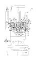
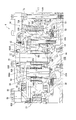
- Sectional drawing which shows the structure of the simple planetary speed reducer which concerns on an example of embodiment of this invention.
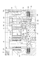
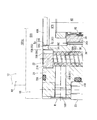
- Partial expanded sectional view which shows the principal part of the said simple planetary reduction gear
- FIG. 1 which shows the modification of the said simple planetary reduction gear
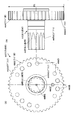
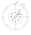
- FIG. 1 which shows the cover body in the simple planetary reduction gear of FIG.
- Sectional drawing equivalent to FIG. 1 which shows the other modification of the said simple planetary gear apparatus.
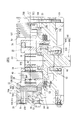
- Sectional drawing which shows the drive unit of the simple planetary reduction gear of FIG. The front view of the cover body of the simple planetary reduction gear of FIG. The principal part enlarged view which shows the air vent passage of the simple planetary reduction gear of FIG.
- FIG. 1 is a sectional view showing a configuration of a simple planetary reduction gear (first stage) according to an example of an embodiment of the present invention
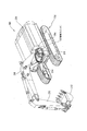
- FIG. 2 is a shovel car (construction machine) in which the simple planetary reduction gear is incorporated.
- FIG. 4 is an overall schematic perspective view of an excavator in which the drive unit is incorporated.
- an upper turning body 206 including a driver's seat 204 is placed on an upper part of a lower traveling body (crawler) 202 so as to be turnable.
- the boom 208, the arm 210, and the attachment 212 are installed in a cantilever state.
- a turning internal gear 214 is fixed to the lower traveling body (crawler) 202, and a final output shaft 216 (described in FIG. 4) of the drive unit 10 attached to the turning internal gear 214 on the upper turning body 206 side.
- the upper revolving body 206 can be swung by meshing the swiveling pinion 218 (not shown).
- the drive unit 10 includes a motor (drive source) 12, and first to third-stage simple planetary speed reducers 14 to 16.
- the motor shaft 12 ⁇ / b> A of the motor 12 is connected to the sun gear 18 of the first stage simple planetary reduction gear 14.
- first stage simple planetary reduction gear 14 may be referred to simply as the reduction gear 14.
- the configuration of the reduction gear 14 near the sun gear 18 will be described in detail later.
- the speed reducer 14 includes in the casing 20 the sun gear 18, a planetary gear 34 that revolves around the sun gear 18 and is supported by the carrier 32, and an internal gear 36 that the planetary gear 34 is in mesh with.
- a simple planetary speed reduction mechanism 38 is provided. In this embodiment, when the shovel car 200 is placed on a horizontal plane, the axis O1 of the simple planetary reduction mechanism 38 of the reduction gear 14 is arranged so as to coincide with the vertical direction.
- the speed reducer 14 is used in a vertical position.
- “used vertically” means that the axis O1 of the simple planetary reduction mechanism 38 is oriented in the vertical direction in a narrow sense, but in the present specification, “oil level L1”. Is intended to encompass the concept of a wider usage mode, such as “use in a mode crossing the axis O1 of the simple planetary reduction mechanism 38”. That is, for example, it includes a case where the axis O1 of the simple planetary reduction mechanism 38 is used in an inclined state on the ground on which the excavator 200 is inclined. In other words, if the angle formed by the axis O1 (the direction thereof) with respect to the vertical direction is within 45 °, it can be said that it is used vertically.
- the reduction gear 14 has an internal gear 36 integrated with the casing 20 (fixed). That is, power is input from the sun gear 18, the planetary gear 34 is revolved with the internal gear 36, and the revolution of the planetary gear 34 is extracted from the carrier 32.
- the planetary gear 34 is supported on the planetary pin 40 via two rows of roller bearings 42.
- the planetary pin 40 is integrated with the carrier 32 by being press-fitted into the carrier 32. Therefore, the revolution of the planetary gear 34 is transmitted to the carrier 32 via the roller bearing 42 and the planetary pin 40.
- the carrier 32 extends from the load side of the simple planetary speed reduction mechanism 38 to the opposite load side (motor 12 side), and the planetary pin 40 is supported on both ends of the (single) carrier 32.
- the carrier 32 is integrated with the output member 44 of the speed reducer 14.
- the output member 44 includes a disk-shaped flange portion 44A connected to the carrier 32, and an output shaft portion 44B extending from the radial center of the flange portion 44A to the load side (lower side).
- a known second stage simple planetary speed reducer 15 and a third stage simple planetary speed reducer 16 are connected to the subsequent stage of the first stage simple planetary speed reducer 14 (see FIG. 2).
- a brake mechanism 50 that brakes the rotation of the output member 44 is attached to the speed reducer (first-stage simple planetary speed reducer) 14.
- the brake mechanism 50 includes a hydraulic chamber 52 to which pressure oil from a hydraulic pump (not shown) is supplied, a piston 54 that slides with the pressure oil supplied to the hydraulic chamber 52, and a coil spring 56 that applies urging force to the piston 54. , And a friction plate set 58.
- the friction plate set 58 is incorporated into the casing 20 so as to be slidable in the axial direction and non-rotatable, and to the flange portion 44A of the output member 44 so as to be slidable in the axial direction and non-rotatable.
- the plurality of rotating friction plates 58B are alternately provided.
- the brake mechanism 50 brakes the rotation of the output member 44 when the stationary side friction plate 58A and the rotation side friction plate 58B are strongly pressed by the urging force of the coil spring 56 in a normal state (when not operating).
- the piston 54 moves upward to release the pressure contact between the fixed side friction plate 58A and the rotation side friction plate 58B and release the output member 44 to a rotatable state.
- Such a brake mechanism 50 can be used to reliably stop the rotation of the output member 44 when the rotation operation is not performed.
- the casing 20 of the first stage simple planetary reduction gear 14 is fitted into a first casing body 21 integrated with the internal gear 36 and a recess 21A formed in a ring shape on the upper surface of the first casing body 21.
- the ring-shaped fourth casing body 24 that bridges the connection is mainly configured.
- the first casing body 21 is provided with the inner teeth 36A of the internal gear 36 on the inner periphery and spring holes 56A for accommodating the coil springs 56 of the brake mechanism 50 at a plurality of locations in the circumferential direction.
- the second casing body 22 has a ring shape that fits into the recess 21 ⁇ / b> A, and closes the opening of the spring hole 56 ⁇ / b> A that accommodates the coil spring 56.
- a part of the inner periphery of the third casing body 23 constitutes a cylinder surface 54 ⁇ / b> A of the piston 54 of the brake mechanism 50.
- the third casing body 23 continues to the load side surface of the first stage simple planetary reduction gear 14, and includes a cylindrical cylindrical portion 23A at the center of the load side surface.
- the output shaft portion 44B of the output member 44 protrudes from the cylindrical body portion 23A to the outside of the casing (the second stage simple planetary reduction gear 15 side).
- a bearing 59 and a bush 60 are press-fitted into the outer periphery of the output shaft portion 44B of the output member 44, and two oil seals 62 are arranged side by side between the bush 60 and the cylindrical portion 23A.
- the side surface on the motor 12 side of the simple planetary reduction gear 14 is closed by a cover body 66 of a motor casing 64 (also serving as a cover for the reduction gear 14).
- the first casing body 21, the third casing body 23, and the fourth casing body 24 are fixed by bolts 78.
- the second casing body 22 is fixed by bolts 83.
- symbol 68 is an air vent hole and 70A-70E are O-rings.
- the drive unit 10 has the above-described configuration, and the rotation of the motor shaft 12A of the motor 12 is sequentially decelerated by the first to third simple planetary reduction devices 14 to 16, and the third simple The decelerated rotation is taken out from the output shaft 116 of the planetary speed reducer 16.
- the turning pinion 218 shown in FIG. 4 is provided on the output shaft 116 of the third stage simple planetary reduction gear 16.
- the turning pinion 218 meshes with the turning internal gear 214 (fixed to the lower traveling body 202) of FIG.
- the turning pinion 218 of the drive unit 10 (attached to the upper turning body 206 side) is rotated, the turning pinion 218 revolves along the turning internal gear 214 while meshing with the turning internal gear 214.
- the car 200 can turn the upper turning body 206 with respect to the lower traveling body 202.
- the sun gear 18, the planetary gear 34, and the internal gear 36 are all constituted by helical gears.
- the sun gear 18 includes a tooth portion 18A and a shaft portion 18B that is continuous with the tooth portion 18A and is coaxial with the axis O1 of the sun gear 18 and protrudes to the load side (output side: lower side). .
- the tooth portion 18A and the shaft portion 18B are both hollow, and a female spline 18C for connecting to the motor shaft 12A is formed at a position corresponding to the inside of the tooth portion 18A. That is, the female spline 18C is formed only at a position substantially corresponding to the inside of the tooth portion 18A, and is not formed on the inner side (inner circumference) of the shaft portion 18B.
- the inner periphery of the shaft portion 18B has an inner diameter D2 that is slightly larger than the root diameter d1 of the female spline 18C.
- a male spline 12C that engages with the female spline 18C is formed (up to the tip) on the motor shaft 12A (see FIG. 2).
- the male spline 12C of the motor shaft 12A engages with the female spline 18C of the sun gear 18 with a “gap”, and the motor shaft 12A reaches the inner position (of the ball bearing 74) of the shaft portion 18B. It is connected to the sun gear 18.
- the male spline 12C of the motor shaft 12A is formed to the tip, the inner diameter D2 of the shaft portion 18B of the sun gear 18 is set to be slightly larger than the root diameter d1 of the female spline 18C.
- the male spline 12C of the motor shaft 12A does not engage with or contact the inner side of the shaft portion 18B.
- the sun gear 18 is supported by a ball bearing 74 disposed between the outer periphery of the shaft portion 18B and the inner periphery 32A of the carrier 32.
- the ball bearing 74 includes an outer ring 74A, rolling elements 74B, and an inner ring 74C.
- the carrier 32 supporting the ball bearing 74 is constituted by a member different from the output member 44.
- the carrier 32 and the output member 44 are connected by a knock pin 77 and a bolt 79.
- the knock pin 77 performs a temporary fixing function when the connection with the bolt 79 is performed, and applies a shear stress to the connection between the carrier 32 and the output member 44.
- the position of the outer ring 74A of the ball bearing 74 in the axial direction is regulated by the output member 44. That is, the flange portion 44A of the output member 44 has an output member side protrusion 44C protruding in the axial direction, while the carrier 32 has a carrier side protrusion 32C in contact with the outer ring 74A of the ball bearing 74 in the radial direction. Protrusively formed. The outer ring 74A of the ball bearing 74 is sandwiched between the output member side projecting portion 44C and the carrier side projecting portion 32C, thereby restricting the position in the axial direction.
- the inner ring 74C of the ball bearing 74 is abutted against a stepped portion 18B1 formed on the shaft portion 18B, and is positioned by a retaining ring 76 fitted on the outer periphery of the shaft portion 18B.
- the sun gear 18 of this embodiment is supported by the ball bearing 74 with such a configuration and is completely accommodated in the casing 20 of the reduction gear 14.
- oil lubricant
- the oil level L1 is higher than the lower end position L2 of the tooth portion 18A of the sun gear 18 and corresponds to a position lower than the upper end position L3 of the sun gear 18. That is, the entire ball bearing 74 is completely immersed in the oil, and the sun gear 18 is approximately immersed in the oil about half of its axial direction (up to the oil level L1).
- JP-T-2006-527119 discloses a planetary gear reduction device.
- the planetary gear reduction device includes a planetary gear reduction mechanism including a sun gear, a planetary gear that revolves around the sun gear and is supported by a carrier, and an internal gear that the planetary gear internally meshes with.
- the shaft member is integrated.
- the shaft member has a large diameter portion and a small diameter portion.
- the spline for connecting a brake mechanism and an output flange is formed in the large diameter part and the small diameter part.
- the output member 44 is a separate member from the carrier 32 and is fixed to the carrier 32.
- the output member 44 includes a flange portion (large diameter portion) 44A and an output shaft portion (small diameter portion) 44B.
- splines 44AA and 44BA of the same module are formed (along the axial direction) on the flange portion 44A and the output shaft portion 44B. Since the flange portion 44A has a larger diameter than the output shaft portion 44B (because of the same module), the flange portion 44A can be formed with more teeth constituting the spline 44AA than the output shaft portion 44B, and the flange portion 44A.
- the outer diameter (length to the tip of the spline 44AA) D1 of the flange portion 44A is smaller than the outermost diameter D2 of the carrier 32.
- the flange portion 44A is provided with a bolt hole 44AB and a knock pin hole 44AC for connection to the carrier 32.
- a recess is provided in the carrier 32 corresponding to the knock pin hole 44AC, and when the carrier 32 and the output member 44 are integrated, the knock pin 77 is fitted therein.
- the knock pin 77 performs a temporary fixing function when the connection with the bolt 79 is performed, and applies a shear stress to the connection between the carrier 32 and the output member 44.
- Reference numeral 44AD is a through hole for allowing oil to flow.
- the recesses 44AE and 44BE at both axial ends of the output member 44 are provided for chucking the output member 44 to the processing apparatus when forming the splines 44AA and 44BA.
- the brake mechanism (brake) 50 is disposed on the outer periphery of the flange portion 44A.
- the rotation side friction plate (friction plate) 58B is formed with a spline that engages with the spline 44AA of the flange portion 44A. For this reason, the rotation side friction plate 58B can be incorporated (arranged) into the flange portion 44A.
- a male spline is also formed on the fixed friction plate 58A.
- the female spline along the axial direction which engages with the male spline is formed in the inner surface of the casing 20. Then, the fixed side friction plate 58 ⁇ / b> A can be incorporated into the casing 20 by being fitted to each other.
- the second stage sun gear 134 provided with a spline that also engages with the spline 44BA can be incorporated into the spline 44BA of the output shaft portion 44B.
- the second stage sun gear 134 is configured to mesh with the second stage planetary gear 118.
- the sun gear 18 is supported on the motor shaft 12A, the sun gear 18 is also attached (when oil is dripping) when the motor 12 is removed during maintenance work, and the work is difficult to perform.
- the sun gear 18 is a helical gear
- the motor 12 is removed while rotating the sun gear 18 along the helical tooth surface, and remounting is performed while rotating the sun gear 18 along the helical tooth surface. Since it has to be done, the operation is very difficult, and the so-called “dents” may be caused by the collision between the tooth surfaces.
- the “positioning means” for positioning the sun gear 18 at a specific position in the vertical direction is disliked. It is necessary to provide. Since the positioning means and the sun gear 18 are “metal contact with relative rotation”, heat generation becomes a problem. In particular, when the sun gear 18 is a helical gear, a thrust load is generated in the sun gear 18 due to meshing with the planetary gear 34, so this problem becomes more prominent.
- the sun gear 18 may be supported by the motor shaft 12A in the conventional method, or may be incorporated in a float state with respect to the motor shaft 12A. It was inevitable that a major problem occurred.
- the motor shaft 12A and the sun gear 18 are connected by the male spline 12C and the female spline 18C that are engaged with a “gap”. Only the motor 12 can be removed while remaining on the 14 side.
- the sun gear 18 remains engaged with the planetary gear 34, so that even if the sun gear 18 is a helical gear, the motor 12 is moved straight in the axial direction, It is only necessary to engage the male spline 12C of the motor shaft 12A straightly with the female spline 18C of the sun gear 18. Therefore, the engagement itself is very simple coupled with the “gap”, and there is no possibility of causing dents on the tooth surfaces of the sun gear 18 and the like.
- the positioning of the sun gear 18 is performed by a ball bearing 74 disposed between the carrier 32 and the shaft portion 18B.
- the outer ring 74A of the ball bearing 74 is positioned with respect to the carrier 32 by sandwiching the outer ring 74A of the ball bearing 74 between the carrier side protrusion 32C and the output member side protrusion 44C,
- the inner ring 74C of the ball bearing 74 is abutted against a step portion 18B1 formed on the shaft portion 18B, and is positioned by a retaining ring 76 fitted on the outer periphery of the shaft portion 18B.
- the sun gear 18 can be positioned in the axial direction via the outer ring 74A, the rolling element 74B, and the inner ring 74C of the ball bearing 74. For this reason, there is no possibility of heat generation due to “metal contact with relative rotation” between the sun gear 18 and its positioning means.
- the sun gear 18 is formed of a helical gear, a thrust load is inevitably generated during power transmission, but this thrust load is also a problem (both forward and reverse rotation). And can be received by the ball bearing 74.
- the ball bearing 74 is completely immersed in oil at a position below the sun gear 18 (to the tooth portion 18A), heat generation of the ball bearing 74 itself can be effectively suppressed.
- the outer ring 74A (for example, compared to the case where the ball bearing 74 is disposed between the casing 20 and the shaft portion 18B). Since the relative speed of the inner ring 74C is small, heat generation is small and the life can be further increased.
- the ball bearing 74 is disposed on the carrier 32 that is substantially integral with the planetary pin 40 that supports the planetary gear 34, the ball bearing 74 (as compared to the case where it is disposed on the casing 20). It is easy to make the revolution axis O4 coincide with the axis O1 of the sun gear 18 (both are designed to be the same as the axis O2 of the carrier 32 by design), and maintain good meshing between the sun gear 18 and the planetary gear 34. be able to.
- the carrier 32 and the output member 44 are separate members and the output member 44 is configured to restrict the position of the outer ring 74A of the ball bearing 74 in the axial direction, a separate part for positioning the ball bearing 74 is required. And not.
- the output member 44 has an output member side protrusion 44C that protrudes in the axial direction, and the output member side protrusion 44C regulates the position of the outer ring 74A of the ball bearing 74 in the axial direction, and the output member side protrusion 44C. Since the outer periphery of the protrusion 44C is used as an inlay portion with the inner periphery 32A of the carrier 32, it is possible to perform axial positioning and radial axial alignment at the same time.
- the tooth portion 18A and the shaft portion 18B of the sun gear 18 are both hollow and the motor shaft 12A can be inserted into the shaft portion 18B beyond the inside of the tooth portion 18A, the length of the motor shaft 12A is short and long. It can respond flexibly.
- a female spline 18C for connection to the motor shaft 12A is formed on the inner side of the tooth portion 18A of the sun gear 18, and the female spline (18C) is formed on the inner side of the shaft portion 18B. Therefore, even when the motor shaft 12A is long, the motor shaft 12A and the inner periphery of the shaft portion 18B do not interfere with each other.
- the present invention can obtain a particularly remarkable effect when the sun gear 18 (the planetary gear 34 and the internal gear 36) is a helical gear.
- the present invention provides a gear other than the helical gear, such as a spur gear. Even in this case, it can be applied and a corresponding effect can be obtained.
- the carrier and the output member are not necessarily separate members, and may be a single member.
- the method of restricting the position of the bearing that supports the sun gear is not particularly limited to the above example, and for example, the position of the bearing may be restricted using a retaining ring or the like.
- the type of bearing is not limited to a ball bearing, and may be a roller bearing, for example.
- the motor shaft does not necessarily need to be able to enter the inside of the shaft portion, and may be configured to enter only the tooth portion of the sun gear, for example.
- the shaft portion is not necessarily hollow and may be solid.
- the motor shaft and the sun gear are connected by a spline by clearance fitting.
- the present invention is not limited to this, and for example, a connection by a key may be adopted. Good.
- the shaft inserted into the sun gear is not limited to the motor shaft, and may be any shaft on the drive source side, for example, a shaft connected to the motor shaft, or a brake mechanism between the motor and the speed reducer. Etc., the output shaft of the brake mechanism or the like may be used.
- components such as the sun gear 18, the planetary gear 34, the internal gear 36, the carrier 32, the output member 44, and the casing 20 are processed and formed. More specifically, since the shape of the carrier 32 is complicated, the carrier 32 is formed by casting, for example. And about the output member 44, recessed part 44AE, 44BE is formed in the columnar member used as the origin, and the said cylindrical member is chucked to a processing apparatus by recessed part 44AE, 44BE. Then, an intermediate member including the flange portion 44A and the output shaft portion 44B without the splines 44AA and 44BA is formed by machining or the like.
- the machining tool of the machining device is changed to a hob (may be reattached to a machining device having a hob shaft different from the above-described machining device), and the intermediate member is fixed together with the hob using the recesses 44AE and 44BE Rotate to create a cutting tooth.
- spline 44AA and 44BA are the same modules, spline 44AA and 44BA are formed with the same hob. That is, the spline of the same module is formed with the same tool on the flange portion 44A and the output shaft portion 44B in the same chucking state with respect to the intermediate member. For this reason, it is possible to efficiently process the output member 44 without changing tools or changing chucking. Appropriate processing / formation is performed on other components.
- the bearing balls 74 are assembled to the sun gear 18. Then, the sun gear 18 and the planetary gear 34 in that state are incorporated into the carrier 32.
- the bearing 59 is disposed on the cylindrical portion 23 ⁇ / b> A of the third casing body 23. Then, the output shaft portion 44 ⁇ / b> B of the output member 44 is attached to the third casing body 23.
- the friction plate set 58 is assembled between the outside of the flange portion 44 ⁇ / b> A of the output member 44 and the inside of the third casing body 23.
- the carrier 32 in which the sun gear 18 and the planetary gear 34 are incorporated and the output member 44 are fixed by a bolt 79 and integrated.
- the piston 54 is assembled along the cylinder surface 54A of the third casing body 23.
- the first casing body 21 is combined with the third casing body 23 so that the internal gear 36 and the planetary gear 34 mesh with each other.
- the 1st casing body 21, the 3rd casing body 23, and the 4th casing body 24 are fixed with the volt
- FIG. 1st casing body 21, the 3rd casing body 23, and the 4th casing body 24 are fixed with the volt
- the coil spring 56 is disposed in the spring hole 56A.
- the second casing body 22 is disposed in the recess 21 ⁇ / b> A, and the second casing body 22 is fixed with the bolts 79.
- the output member 44 is a separate member from the carrier 32.
- the output member 44 is not limited by the shape and size of the carrier 32. That is, when the output member 44 and the carrier 32 are integrated, it is necessary to design the diameter of the flange portion 44A so that a tool (such as a hob) for forming the splines 44AA and 44BA does not interfere with the carrier 32.
- a tool such as a hob
- the diameter of the flange portion 44A can be designed without such restrictions, and the degree of freedom in design can be improved (for example, the axial distance between the flange portion and the output shaft portion is increased).
- the difference in diameter is not increased, and if the axial distance between the flange portion and the output shaft portion is relatively long, the difference in diameter may be increased or decreased.
- optimum processing means can be selected for the carrier 32 and the output member 44, respectively. For this reason, it is possible to promote optimization of the carrier 32 and the output member 44 from the functional and manufacturing aspects.
- the materials and materials of the carrier 32 and the output member 44 are not specified, but other materials and materials may be used from the viewpoint of optimization.
- the rotation side friction plate 58B is disposed on the spline 44AA of the flange portion 44A of the output member 44 which is a separate member from the carrier 32, and the outer diameter D1 of the flange portion 44A is the outermost diameter of the carrier 32. It is smaller than the outer diameter D2. That is, in this embodiment, the configuration as shown in JP-T-2006-527119 (the carrier is integrally formed up to the output shaft portion, so the outer diameter of the flange portion is related to the outer diameter of the carrier.
- the outer diameter of the friction plate set 58 including the rotation side friction plate 58B can be reduced without being affected by the outer diameter of the carrier 32, compared to the configuration in which the outer diameter of the carrier is made larger.
- the amount of heat generated in the reduction gear tends to increase when the oil agitation region introduced into the reduction gear is wide. For this reason, compared with the configuration shown in Japanese Patent Publication No. 2006-527119, the outer diameter of the friction plate set 58 can be made smaller and the oil agitation region can be made smaller, so that the amount of generated heat can be suppressed.
- splines 44AA and 44BA of the same module are formed on the flange portion 44A and the output shaft portion 44B. For this reason, each of the flange portion 44A and the output shaft portion 44B of the output member 44 can be processed using the same tool and in the same processing step. That is, it is not necessary to change the tool, and the processing time of the output member 44 can be shortened. Since the flange portion 44A has a larger diameter than the output shaft portion 44B, the power transmitted from the output shaft portion 44B can be reliably braked by the brake mechanism 50 of the flange portion 44A.
- a planetary reduction device including a planetary reduction mechanism includes a shaft member that is integrated with a carrier of the planetary reduction mechanism, the shaft member having a large diameter portion and a small diameter portion, The small-diameter portion may be configured so that splines of the same module are formed.
- the shaft member may be a separate member from the carrier and fixed to the carrier.
- a brake friction plate is disposed on the spline of the large diameter portion, and the outer diameter of the large diameter portion is smaller than the outermost diameter of the carrier.
- (A4) In terms of a method of manufacturing a planetary reduction device that includes a planetary speed reduction mechanism, and a shaft member having a large diameter portion and a small diameter portion is integrated with a carrier of the planetary speed reduction mechanism, the shaft member is chucked. And a step of forming splines of the same module on the large diameter portion and the small diameter portion with the same tool in the same chucking state.
- the carrier 32 and the output member 44 are separate members, but the present invention is not limited to this and may be a single member.
- the shaft member does not have to be an output member for taking out an output, and may be a member used for power transmission on the way.
- the rotation side friction plate 58B of the brake mechanism 50 is disposed on the spline 44AA of the flange portion 44A, and the outer diameter D1 of the flange portion 44A is smaller than the outermost diameter D2 of the carrier 32.
- the present invention is not limited to this.
- the outer diameter of the flange portion may be larger than the outermost diameter of the carrier. In that case, the brake torque per sheet can be increased, and the number of friction plate sets can be reduced.
- a mechanism for example, a clutch mechanism, a pulley mechanism, or the like
- a mechanism that suppresses and controls the rotational torque of the output member may be disposed on the spline of the flange portion instead of the rotation side friction plate of the brake mechanism. That is, it is not limited to what kind of member the splines of the large diameter part and the small diameter part are used for connection.
- the planetary gear reduction device is a simple planetary reduction device having a simple planetary gear.
- the present invention is not limited to this, and can be widely applied to devices including a reduction mechanism having a planetary gear. Can do.
- a cover body 66 of a motor casing 64 is disposed on the motor 12 side of the simple planetary reduction gear 14.
- the cover body 66 is also used as a cover of the speed reducer 14 and closes the side surface of the simple planetary speed reducer 14 on the motor 12 side. That is, the cover body 66 is a member for partitioning the motor 12 and the simple planetary speed reducing device 14 and covers the upper part of the simple planetary speed reducing mechanism 38.
- the cover body 66 includes a flange portion 66A and an inclined portion 66B.
- the flange portion 66A is formed integrally with the motor casing 64, and is provided with a through hole 66AB through which the motor shaft 12A passes.
- An oil seal 63 is disposed in the through hole 66AB.
- the inclined portion 66B is also provided with a through hole 66BB through which the motor shaft 12 passes, and a continuous inclined surface inclined downward from the outside toward the inside in the radial direction of the sun gear 18 on the surface on the simple planetary reduction mechanism 38 side. S.
- the inclination of the inclined surface S is constant.
- the terminal position on the inner side in the radial direction of the inclined surface S extends to the very vicinity of the motor shaft 12A on the inner side of the position P1 of the outermost diameter of the sun gear 18. That is, the end position on the radially inner side of the inclined surface S (the radially inner end of the inclined portion 66 ⁇ / b> B) is located on the radially inner side of the oil seal 63.
- the inclined surface S is formed from the position overlapping the internal gear 36 of the cover body 66 to the side surface contacting the inner surface of the first casing body 21 when viewed from the axial direction (in this embodiment, The position where the inclined surface S overlaps with the internal gear 36 of the cover body 66 when viewed from the axial direction is the middle position of the inclined surface S, but may be the starting point (end) of the inclined surface S) .
- recesses 66BA are intermittently provided in the circumferential direction at a predetermined diameter R11 centered on the axis O1.
- the concave portion 66BA is provided with an inclined portion S which is inclined downward so as to be discontinuous there, and allows the lubricating oil guided along the inclined surface S to be retained by the concave portion 66BA (the presence of the concave portion 66BA exists).
- the predetermined diameter R11 coincides with the distance R11 to the axis of the revolving planetary gear 34 (the axis of the planetary pin 40).
- the flange portion 66A is integrated with the inclined portion 66B by a bolt 81 that engages with a bolt hole 66BC provided in the inclined portion 66B. That is, the inclined portion 66 ⁇ / b> B has a separate structure in the cover body 66.
- reference numeral 66 ⁇ / b> AA is a bolt hole with which a bolt 80 for connecting the motor 12 and the speed reducer 14 is engaged.
- the planetary pin 40 is provided with a lubrication passage 40A.
- the lubrication passage 40A includes one axial passage 40B and a plurality of horizontal passages 40C extending radially perpendicular to the axial passage 40B.
- the axial passage 40B is provided so as to penetrate the planetary pin 40 in the axial direction at the axis of the planetary pin 40. That is, when viewed from the axial direction, the position of the axial passage 40B coincides with the position of the recess 66BA of the inclined portion 66B.
- the recess 66BA is intermittently provided in the revolving direction of the planetary gear 34 at a position above the axial passage 40B (of the lubrication passage 40A) of the cover body 66.
- the horizontal passage 40C extends in the radial direction of the planetary pin 40 and is provided so as to penetrate the planetary pin 40 at a position where two rows of roller bearings 42 are adjacent to each other.
- lubricating oil is sealed up to an oil level L ⁇ b> 1 corresponding to a position substantially in the center of the sun gear 18 in the axial direction.
- the oil level L1 is higher than the lower end position of the tooth portion 18A of the sun gear 18 and corresponds to a position lower than the upper end position of the sun gear 18. That is, the amount of lubricating oil that exposes at least a part of the sun gear 18, the planetary gear 34, and the internal gear 36 is sealed in the casing 20 regardless of whether or not the speed reducer 14 is rotating.
- the greater the amount of lubricating oil the greater the stirring resistance. Therefore, the amount of heat generated increases as more lubricating oil is stirred. For this reason, the lubricating oil sealed in the casing 20 in order to suppress the heat generation amount is not full in the present embodiment, but is an appropriate amount.
- the lubricating oil is scattered obliquely upward rather than downward when rotating in one direction. That is, the oil droplets directly adhere to the cover body 66 due to the scattering, or the oil surface of the lubricating oil becomes a steep mortar state (compared to a simple spur gear). Then, in the mortar state, the level of the oil level becomes low, and there is a risk that the sun gear 18 may be in a state where it is hardly immersed in the oil surface.
- the occurrence of this phenomenon itself is the same as in the prior art (see, for example, Japanese Patent Application Laid-Open No. 2012-122552) and this embodiment.
- the oil level directly contacts the inclined surface S at a position overlapping with the internal gear 36 as viewed from the axial direction, that is, at the position of the edge of the mortar state.
- the lubricating oil attached to the inclined surface S at the contacted position is guided radially inward by the inclined surface S together with the oil droplets directly attached to the cover body 66.
- the lubricating oil is retained in the concave portion 66BA provided in the inclined surface S. For this reason, the corresponding lubricating oil is dropped downward at the position of the recess 66BA. This position is the position of the axis of the planetary pin 40. For this reason, the dripped lubricating oil is introduced into the lubricating passage 40A from the upper end opening of the axial passage 40B, if not all (in this embodiment, the bolt hole 66BC is also recessed with respect to the planetary pin 40.
- the bolt 81 arranged in the bolt hole 66BC has the same effect as that of the recess 66BA because it has the same positional relationship as 66BA.
- the lubricating oil introduced into the lubricating passage 40A is supplied from the horizontal passage 40C to the two-stage roller bearing 42 via the axial passage 40B. That is, the lubricating oil introduced into the lubricating passage 40A can more smoothly rotate the planetary gear 34 with respect to the planetary pin 40.
- the lubricating oil is guided to the radially inner side from the position P1 of the outermost diameter of the sun gear 18, and the lubricating oil appropriately reaches the motor shaft 12A. Therefore, the lubricating oil reaching the motor shaft 12A can directly lubricate the fitting portion between the motor shaft 12A and the sun gear 18 and the meshing portion between the sun gear 18 and the planetary gear 34. Further, the lubricating oil guided to the radially inner side without reaching the motor shaft 12A can directly lubricate the meshing portion of the sun gear 18 and the planetary gear 34 when dropped.
- the cover body 66 that covers the simple planetary reduction mechanism 38 has a continuous inclined surface S that is inclined downward from the outside toward the inside in the radial direction of the sun gear 18.
- the lubricating oil adhering to the cover body 66 among the lubricating oil scattered by the rotation of the sun gear 18 can be guided along the inclined surface S to the inside in the radial direction.
- the lubricating oil is moved to a position radially inward of the position attached to the cover body 66 (rather than dropping the lubricating oil downward at the position attached to the cover body 66) and dropped downward from the cover body 66. can do. That is, according to the present embodiment, it is possible to promote the supply of lubricating oil to the sun gear 18 that rotates at the highest speed.
- the member (inclined part 66B) of the part which comprises the inclined surface S is made into the separate structure in the cover body 66.
- the oil seal 63 can be incorporated in the flange portion 66A of the cover body 66, and the inclined portion 66B having the inclined surface S can be disposed so as to cover it.
- the oil seal 63 required between the cover body 66 and the motor shaft 12A can be easily assembled.
- the inclined surface S is optimally arranged without being restricted by the position of the oil seal 63 while the oil seal 63 is disposed and used to securely seal the lubricating oil of the casing 20 as is normally used. Can be provided.
- the end position on the radially inner side of the inclined surface S can be set on the radially inner side of the oil seal 63.
- the inclined portion 66B has a separate configuration, it is possible to replace only the inclined portion 66B as appropriate according to the usage state of the speed reducer 14 without changing the flange portion 66A.
- the inclination of the inclined surface S is constant, but the inclination may not be constant.
- the inclined surface S may be a curved surface.
- the “continuous inclined surface” only needs to be continuously inclined in a specific range in the circumferential direction, and only a specific position (or range) in the circumferential direction such as the concave portion 66BA and the bolt 81 described above. Discontinuity is not prohibited (included in the concept of “continuous sloping surfaces”). That is, it is not always necessary that the surface corresponding to the inclined surface S is continuous in all the circumferential and radial directions.
- the sun gear 18, the planetary gear 34, and the internal gear 36 are helical gears. Therefore, the degree of increase in the oil level of the lubricating oil varies greatly depending on the direction of the sun gear 18 in the rotational direction. It was. For this reason, although it was suitable for this invention with respect to the said embodiment, this invention is not limited to this.
- the sun gear, the planetary gear, and the internal gear may be spur gears.
- the radially inner terminal position of the inclined surface S is set to the inner side of the outermost diameter position P1 of the sun gear 18, and the internal gear of the cover body 66 is viewed from the axial direction.
- the inclined surface S is also provided at the position overlapping with 36, the present invention is not limited to this.
- the end position on the inner side in the radial direction of the inclined surface S may be outside the position of the outermost diameter of the sun gear, and the inclined surface S is located at a position overlapping the internal gear of the cover body when viewed from the axial direction. It may not be provided. Even in such a case, since the lubricating oil is guided radially inward than the lubricating oil dropped downward at the position attached to the cover, the supply of the lubricating oil to the sun gear can be promoted.
- the inclined part 66B which comprises the inclined surface S was made into the different body structure in the cover body 66, it is not limited to this, You may be comprised integrally.
- the planetary pin 40 is provided with the lubrication passage 40A, and the recess 66BA is intermittently provided in the revolving direction of the planetary gear 34 at the position above the lubrication passage 40A of the cover body 66.
- the present invention is not limited to this, and a convex portion may be provided instead of the concave portion 66BA. Even in that case, the lubricating oil guided to the inclined surface S is stopped there, and the lubricating oil can be dropped at that position.
- the planetary pin may not be provided with a lubrication passage, and the cover may not be provided with the concave portion.
- the cover body 66 was a member for partitioning the motor 12 arrange
- the speed reducer at the front stage is disposed above, it may be a member for partitioning the speed reducer at the front stage from the simple planetary speed reduction mechanism, and the speed reducer at the rear stage is disposed above. If it is (that is, the image of the drive unit upside down), it may be a member for partitioning the subsequent reduction gear and the simple planetary reduction mechanism.
- this invention is not limited to this, A sun gear, Lubricating oil in such an amount that all of the planetary gear and the internal gear may be immersed may be enclosed.
- a simple planetary gear reduction mechanism that includes a sun gear, a planetary gear that revolves around the sun gear and is supported by a carrier, and a simple planetary reduction mechanism that has an internal gear with which the planetary gear internally meshes.
- the cover that covers the top of the simple planetary reduction mechanism may be configured to have a continuous inclined surface that is inclined downward from the outside toward the inside in the radial direction of the sun gear.
- the sun gear, the planetary gear and the internal gear are preferably helical gears (because of high performance, a helical gear having disadvantages in terms of the inclination of the liquid level can be applied without problems). .
- the end position on the radially inner side of the inclined surface is preferably set on the inner side of the position of the outermost diameter of the sun gear.
- the radially inner end portion of the member constituting the inclined surface may be positioned more radially inward than the oil seal disposed on the cover.
- the inclined surface may be provided at a position overlapping the internal gear of the cover as viewed from the axial direction.
- a planetary pin that rotatably supports the planetary gear may be provided with a lubrication passage, and a convex portion or a depression may be provided intermittently in the circumferential direction at a position above the lubrication passage of the cover.
- the casing 20 is mainly configured by the first to fourth casing bodies 21 to 24.
- the first casing body 21 (first member) includes an air vent 100.
- An internal gear 36 is integrated with the first casing body 21, and internal teeth 36 ⁇ / b> A of the internal gear 36 are formed on the inner periphery.
- the first casing body 21 is formed with spring holes 56A along the axial direction for accommodating the coil springs 56 of the brake mechanism 50 at a plurality of locations (eight locations in this example) in the circumferential direction.
- a ring-shaped recess 21A is formed in the upper part of the spring hole 56A.
- the second casing body 22 (second member) has a ring shape that fits into the recess 21 ⁇ / b> A formed in the first casing body 21, and closes the spring hole 56 ⁇ / b> A (accommodating the coil spring 56) with the bolt 101. ing.
- the third casing body 23 is connected to the lower side of the first casing body 21. A part of the inner periphery of the third casing body 23 constitutes a cylinder surface 54 ⁇ / b> A of the piston 54 of the brake mechanism 50.
- the third casing body 23 continues to the load side surface of the first stage simple planetary reduction gear 14, and includes a cylindrical cylindrical portion 23A at the center of the load side surface.
- the fourth casing body 24 has a ring shape and bridges the connection with the casing 26 (FIG. 2) of the second stage simple planetary reduction gear 15.
- the output shaft portion 44B of the output member 44 protrudes from the cylindrical portion 23A to the outside of the casing (on the second stage simple planetary reduction gear 15 side).
- a bush 60 is press-fitted into the outer periphery of the output shaft portion 44B of the output member 44, and two oil seals 62 are arranged side by side between the bush 60 and the cylindrical portion 23A. The lower side of the oil space in the 14 casings 20 is sealed.
- This simple planetary speed reduction mechanism 38 is arranged at the next stage of the motor 12 (a space such as a brake chamber is not interposed between the motor 12 and the simple planetary speed reduction mechanism 38). That is, the upper space SP1 of the simple planetary speed reduction mechanism 38 is closed by the cover body (cover) 66 of the motor casing 64 (also serving as the cover of the speed reduction device 14) (in other words, above the cover body 66).
- the space SP3 is a motor internal space). Therefore, basically, the upper space SP3 of the cover body 66 covering the upper space SP1 of the simple planetary deceleration mechanism 38 cannot be used as a passage for guiding oil or a buffer space capable of storing oil.
- FIG. 12 is an enlarged view of a main part showing the air vent passage R.
- FIG. 12 is an enlarged view of a main part showing the air vent passage R.
- the simple planetary speed reduction device 14 includes the air vent 100 provided in the casing 20 and a buffer tank 102 that is disposed outside the casing 20 (of the first casing body 21) and connected to the air vent 100 by screw connection. (See FIG. 10), and an air vent passage R that communicates the air vent 100 and the upper space SP1 of the simple planetary reduction mechanism 38.
- the air vent passage R actively utilizes the fact that the casing 20 is divided into a first casing body 21 (first member) and a second casing body 22 (second member).
- the main ventilating passage 104 constituting the first passage R1 of the air vent passage R is connected to the air vent 100.
- the main cylindrical path 104 extends radially inward from the air vent path R and does not open directly into the upper space SP1 of the simple planetary reduction mechanism 38.
- “not directly opening in the space above the simple planetary speed reduction mechanism” means that the air vent passage R extends radially inward from the air vent 100 and is directly above the simple planetary speed reduction mechanism 38. This means that the mode does not reach the space SP1.
- the main cylindrical path 104 directly opens into a spring hole 56A (a space different from the upper space SP1 of the simple planetary speed reduction mechanism 38) that houses the coil spring 56 of the brake mechanism 50 of the simple planetary speed reduction mechanism 38. ing. That is, in this embodiment, the spring hole 56A constitutes the second passage R2 of the air vent passage R.
- the spring hole 56A is provided in the first casing body 21, and the second casing body 22 (which is not formed with the spring hole 56A) closes the spring hole 56A together with the bolt 101.
- a gap 106 between the first casing body 21 (the recess 21A thereof) and the second casing body 22 communicates with the upper space SP1 of the simple planetary reduction mechanism 38 as the third passage R3 of the air vent passage R. (More specifically, it communicates with the upper space SP1 of the simple planetary reduction mechanism 38 via the remaining portion of the air vent passage R to be described below).
- the inter-case enlarged gap portion 108 (the portion with a larger gap) is formed on the gap 106 side of the second casing body 22. ) Is formed.
- the inter-case enlarged gap portion 108 includes a part of the second casing body 22 (more specifically, a part in the circumferential direction on the first casing body 21 side) at a plurality of locations (eight locations in the illustrated example) in the axial direction. Is formed by cutting out into a semicircular shape along (see FIG. 11).
- the inter-case enlarged gap portion 108 functions as a fourth passage R4 of the air vent passage R, and assists air passing through the gap 106 (third passage R3).
- the upper space SP1 of the simple planetary reduction mechanism 38 is closed by the cover body 66 of the motor 12.
- the first casing body 21 and the cover body 66 are fitted via a pair of spigot fitting surfaces Ip.
- the inlay fitting surface Ip has a vertical step portion 66C between the flange portion 66A of the cover body 66 and the thick central portion 66K in the radial direction, and the inner periphery of the first casing body 21 facing the step portion 66C. It is comprised with the edge part 21B. Since the inlay fitting surface Ip (the stepped portion 66C and the inner peripheral end portion 21B of the first casing body 21) is a gap fit, there is a gap 92.
- the gap 92 of the spigot fitting surface Ip is utilized as the fifth passage R5 of the air vent passage R.
- the fifth passage R5 communicates the gap 106 (third passage R3) between the first casing body 21 and the second casing body 22 and the upper space SP1 of the simple planetary reduction mechanism 38.
- the gap 92 of the inter-lobe fitting surface Ip may not be present (the gap may be 0 or an interference fit).
- the air in the upper space SP1 of the simple planetary speed reduction mechanism 38 can pass through the gap 92 (fifth passage R5) of the spigot fitting surface Ip.
- an enlarged inter-brow surface gap portion (a portion having a larger gap) 94 is formed in a part of the circumferential direction of the spigot fitting surface Ip.
- the inter-spread surface expansion gap 94 has a plurality of portions (more specifically, a portion in the peripheral direction of the inner peripheral end portion 21B of the first casing body 21) in the circumferential direction of the spigot fitting surface Ip.
- the inter-spread surface expansion gap portion 94 functions as the sixth passage R6 of the air vent passage R, and assists air to pass through the clearance 92 (fifth passage R5) of the spigot fitting surface Ip.
- the air vent path R between the air vent 100 and the upper space SP1 of the simple planetary speed reducing mechanism 38 includes the first path R1 constituted by the main cylindrical path 104 and the coil spring 56 of the brake mechanism 50.
- the third passage R3 constituted by the gap 106 between the first casing body 21 and the second casing body 22, and the gap 106 (third passage R3).
- the fifth passage R5 is configured by a gap 92 (the fifth passage R5). It will be composed by the sixth passage R6 being.
- a buffer tank 102 disposed outside the casing 20 is connected to the air vent 100 by screw connection.
- the capacity of the buffer tank 102 is kept smaller than the conventional one.
- reference numerals 70A to 70E are O-rings.
- the O-ring 70 ⁇ / b> A is located at the radially outer position of the first casing body 21 than the gap 106 between the first casing body 21 and the second casing body 22.
- the cover body 66 of the motor 12 (the space between the casing 20 and the cover body 66 is closed by an O-ring 70A).
- reference numerals 90 and 96 in FIG. 10 are oil gauges for detecting the oil level
- reference numeral 96A is a dipstick (a bar-shaped instrument that detects the oil level by changing the color by dipping in the oil). is there.
- the two oil gauges 90 and 96 are provided because the drive unit 10 has two oil enclosing spaces.
- the oil gauge 96 corresponds to an oil gauge that detects the oil level L1 in the casing 20 of the reduction gear 14. In this embodiment, the oil level L1 in the casing 20 is set low (substantially in the axial center position of the sun gear 18).
- the air vent passage R is not directly open to the upper space SP1 of the simple planetary speed reduction mechanism 38, and in particular, the gap 106 between the first casing body 21 and the second casing body 22 ( It communicates with the upper space SP1 of the simple planetary reduction mechanism 38 via the third passage R3). For this reason, even if the oil in the upper space SP1 has a mortar shape, it cannot easily pass through the air vent passage R. As a result, only the air to be discharged is buffered through the air vent passage R. 102 side can be passed.
- the air in the upper space SP1 of the simple planetary speed reduction mechanism 38 is the fifth passage R5 (+ the sixth inter-lobe surface expanding gap portion 94) configured by the clearance 92 of the spigot fitting surface Ip. Passage R6), a third passage R3 constituted by a gap 106 between the first casing body 21 and the second casing body 22 (+ a fourth passage R4 constituted by an enlarged inter-case gap 108), and a spring hole 56A.
- the air passage 100 reaches the air vent 100 through the second passage R ⁇ b> 2 constituted by the above and the first passage R ⁇ b> 1 constituted by the main cylindrical passage 104, and escapes to the buffer tank 102 connected to the air vent 100.
- the amount of oil in the casing 20 can always be kept substantially constant, so the initial oil level L1 is set low (for example, a level near the center in the axial direction of the sun gear 18). This makes it possible to maintain a high lubricating function while reducing the stirring resistance.
- the first casing body 21 (first member) is fitted to the cover body 66 via the spigot fitting surface Ip, and above the simple planetary reduction mechanism 38.
- the space SP1 is communicated with the gap 106 (third path R3) between the first casing body 21 and the second casing body 22 via the gap 92 (fifth path R5) of the spigot fitting surface Ip. .
- the oil has not passed through the clearance 92 (fifth passage R5) of the spigot fitting surface Ip, and the first casing body 21 and the first casing body 21 in the air vent passage R from the upper space SP1 of the simple planetary reduction mechanism 38. Since it does not enter the gap 106 (third passage R3) side between the two casing bodies 22, the oil can be further prevented from flowing out.
- a portion where the gap 92 is enlarged is formed, and this is defined as a sixth passage R6.
- the inter-spread surface enlarged gap portion 94 (sixth passage R6) is small for oil to pass through, but is large enough for air to pass through, and therefore allows air to pass more than oil. Will be able to.
- the gap 106 is also provided.
- a case-to-case enlarged gap portion 108 (a portion in which the gap 106 is enlarged) is formed, and this is defined as a fourth passage R4.
- the inter-case enlarged gap portion 108 (fourth passage R4) is also small for oil to pass through, but is large enough for air to pass through, so that air can be passed more than oil relatively. Will be able to.
- the air vent passage R connected to the air vent 100 opens directly to the spring hole 56A, and the spring hole 56A constitutes the second passage R2.
- the coil spring 56 disposed in the spring hole 56A is resistant to the passage of oil, but air can pass through without any problem. Therefore, here too, air can be passed more than oil.
- the buffer tank 102 is provided.
- the buffer tank since the oil can be almost prevented from flowing out, the buffer tank may not be necessary (may be unnecessary) depending on the use environment. .
- the capacity of the buffer tank can be suppressed or made unnecessary, but it is not necessarily required to be suppressed or made “none”.
- the operation may be directed to the effect of “more reliably preventing the phenomenon of oil overflowing from the buffer tank” after providing a buffer tank similar to the conventional one.
- the effect of lowering the level in the casing than before (the amount of oil enclosed can be reduced) is obtained, but it is not always essential to lower the oil level than before, for example, Alternatively, the oil level may be maintained at the same level as the conventional one, and the oil level may be further improved. Even in this case, since most of the oil in the casing is held in the casing, there is no need to proportionally increase the buffer tank.
- the air vent passage does not open directly to the upper space of the simple planetary speed reduction mechanism, but communicates with the upper space of the simple planetary speed reduction mechanism through a gap between the first member and the second member.
- the configuration is essential, there is no particular limitation on how the other configuration of the air vent passage is specifically realized.
- the spigot fitting surface between the first member and the cover body does not necessarily need to be a part of the air vent passage, and a gap between the first member and the cover body is formed in a part of the circumferential direction of the spigot fitting surface. There is no need to form a portion with a larger diameter.
- the notch A groove may be provided.
- through holes may be formed, or protrusions or spacers that contact only a part (or leave only a part) may be arranged. Such a deformation is also possible when the enlarged gap portion between the cases is formed.
- (C1) In a simple planetary reduction device that includes a simple planetary reduction mechanism having a sun gear, a planetary gear, and an internal gear, and is used in a vertical arrangement in connection with a motor, the simple planetary reduction device is provided at the next stage of the motor.
- a mechanism is arranged, and the internal gear is integrated with a casing of the simple planetary speed reduction mechanism, and an air vent that connects the air vent provided in the casing and the space above the simple planetary speed reduction mechanism.
- the casing is divided into at least a first member and a second member, and the air vent passage is not directly open to an upper space of the simple planetary reduction mechanism, and the first member and It is good to set it as the structure connected to the upper space of the said simple planetary reduction mechanism through the clearance gap between 2nd members.
- the cover of the motor closes the space above the simple planetary reduction mechanism, and the first member is fitted to the cover via the spigot fitting surface, and the simple planetary reduction
- the upper space of the mechanism may be configured to communicate with the gap between the first member and the second member via the gap between the spigot fitting surfaces.
- the casing is provided with a spring hole that accommodates a spring of the brake mechanism of the simple planetary reduction mechanism, and the air vent passage opens directly into the spring hole, and the spring hole is a part of the air vent passage. It is even better if they are configured.
- the application of the present invention is not limited to the excavator turning device, but can be applied to various simple planetary reduction devices.
Landscapes
- Engineering & Computer Science (AREA)
- General Engineering & Computer Science (AREA)
- Mechanical Engineering (AREA)
- Mining & Mineral Resources (AREA)
- Civil Engineering (AREA)
- Structural Engineering (AREA)
- Retarders (AREA)
Abstract
太陽歯車18、該太陽歯車18の周りで公転しキャリヤ32に支持された遊星歯車34、および該遊星歯車34が内接噛合する内歯歯車36を備え、縦置き状態で使用される単純遊星減速装置14であって、太陽歯車18は、該太陽歯車18の軸心O1と同軸に負荷側(下側)に突出された軸部18Bを有し、該軸部18Bは、当該軸部18Bの外周とキャリヤ32の内周32Aとの間に配置された玉軸受74によって支持される。これにより、高いメンテナンス性を確保すると共に、発熱の問題を抑制する。
Description
本発明は、単純遊星減速装置に関する。
日本国、特開2011-236950号公報に建設機械の旋回装置が開示されている。
この旋回装置は、単純遊星減速装置を備えている。単純遊星減速装置は、太陽歯車、該太陽歯車の周りで公転しキャリヤに支持された遊星歯車、および該遊星歯車が内接噛合する内歯歯車を備え、縦置き、すなわち、単純遊星減速装置の軸心を鉛直方向に向けた状態で使用される。
単純遊星減速装置の太陽歯車は、モータのモータ軸にスプラインを介して一体回転可能に連結されている。従来、この種の単純遊星減速装置においてモータ軸と太陽歯車とを連結するためのスプラインの設計には2通りの手法が提案されている。
1つは、スプラインの嵌合を締まり嵌めに設定する設計である。この設計によれば、太陽歯車の支持をモータ軸側のみで完結させることができるようになる。モータ軸に太陽歯車を直切りする設計もこの範疇の設計に入る。
もう1つは、スプラインの嵌合を隙間嵌めに設定する設計である。
しかしながら、太陽歯車をモータ軸に支持させる設計は、メンテナンス作業等においてモータを取り外す際に、太陽歯車がモータ軸側に設けられた状態のまま分解されることから、メンテナンス作業がしにくくなる、という問題がある。
一方、太陽歯車をモータ軸に対して隙間嵌めする設計は、減速装置側で該太陽歯車を特定の軸方向位置に支持する構成が必要である。通常、止め輪、あるいは突起部等で太陽歯車を挟み込み、該太陽歯車の軸方向の位置規制を行うが、これらの止め輪や突起部と太陽歯車との接触部分は、必然的に「相対回転を伴う金属接触」となるため、発熱が問題となる。
本発明は、このような従来の問題を解消するためになされたものであって、高いメンテナンス性を確保すると共に、発熱の問題を抑制することのできる単純遊星減速装置を提供することをその課題としている。
本発明は、太陽歯車、キャリヤに支持された遊星歯車、および該遊星歯車が内接噛合する内歯歯車を備え、縦置き状態で使用される単純遊星減速装置であって、前記太陽歯車は、該太陽歯車の軸心と同軸に負荷側に突出された軸部を有し、該軸部は、当該軸部の外周と前記キャリヤの内周との間に配置された軸受によって支持される構成とすることにより、上記課題を解決したものである。
本発明に係る単純遊星減速装置の太陽歯車は、該太陽歯車の軸心と同軸に負荷側(下側)に突出された軸部を有する。そして、この軸部の外周と、キャリヤの内周との間に配置された軸受によって太陽歯車を支持する。
この構成により、モータを取り外した際に、太陽歯車は減速装置側に残るようにできるため、メンテナンス性を高く維持することができる。
また、太陽歯車は、軸受によって回転自在に支持されることにより軸方向位置が保持されるため、発熱を抑制できる。
本発明によれば、高いメンテナンス性を確保すると共に、発熱の問題を抑制することのできる単純遊星減速装置を得ることができる。
以下、図面に基づいて本発明の実施形態の一例を詳細に説明する。
図1は、本発明の実施形態の一例に係る(1段目の)単純遊星減速装置の構成を示す断面図、図2は、該単純遊星減速装置が組み込まれたショベルカー(建設機械)の旋回装置の駆動ユニットを示す断面図である。また、図4は、該駆動ユニットが組み込まれたショベルカーの全体概略透視図である。
始めに、駆動ユニット10が組み込まれたショベルカー200の全体概略構成から説明する。
図4を参照して、このショベルカー200は、下部走行体(クローラ)202の上部に運転席204を含む上部旋回体206が旋回可能に載置されている。上部旋回体206からは、ブーム208、アーム210、及びアタッチメント212が片持ち状態で据え付けられている。下部走行体(クローラ)202には、旋回内歯歯車214が固定されており、この旋回内歯歯車214に上部旋回体206側に取り付けた駆動ユニット10の後述する最終出力軸216(図4では符号略)の旋回ピニオン218が噛合することにより、上部旋回体206が旋回できるような構成とされている。
次に、図2を参照して、駆動ユニット10の概略を説明する。
駆動ユニット10は、モータ(駆動源)12、1段目~3段目の単純遊星減速装置14~16を備える。モータ12のモータ軸12Aは、1段目の単純遊星減速装置14の太陽歯車18と連結されている。
なお、以降「1段目の単純遊星減速装置14」を単に減速装置14とのみ称することがある。減速装置14の太陽歯車18の近傍の構成については、後に詳述する。
減速装置14は、ケーシング20の中に、当該太陽歯車18、該太陽歯車18の周りで公転しキャリヤ32に支持された遊星歯車34、および該遊星歯車34が内接噛合する内歯歯車36を有する単純遊星減速機構38を備える。本実施形態では、ショベルカー200が水平面上に置かれたときに、減速装置14の単純遊星減速機構38の軸心O1が鉛直方向と一致するように配置される。
すなわち、減速装置14は、縦置きで使用される。ここで、「縦置きで使用」とは、狭義には単純遊星減速機構38の軸心O1を鉛直方向に向けた状態で使用することを意味するが、本明細書においては、「オイルレベルL1が、単純遊星減速機構38の軸心O1と交差する態様での使用」という、より広い使用態様の概念を包含しているものとする。すなわち、例えば、ショベルカー200が傾いた地面上において単純遊星減速機構38の軸心O1が傾いた態様で使用される場合等を含む。別の言い方をすれば、軸心O1(の方向)が鉛直方向に対してなす角度が45°以内であれば縦置きでの使用であると言える。
図1を参照して、この減速装置14は、内歯歯車36がケーシング20と一体化されている(固定されている)。すなわち、太陽歯車18から動力を入力し、遊星歯車34を内歯歯車36との間で公転させ、この遊星歯車34の公転をキャリヤ32から取り出す構成とされている。遊星歯車34は、遊星ピン40に2列のローラ軸受42を介して支持されている。遊星ピン40は、キャリヤ32に圧入されることで該キャリヤ32と一体化されている。このため、遊星歯車34の公転は、該ローラ軸受42および遊星ピン40を介してキャリヤ32に伝えられる。なお、キャリヤ32は単純遊星減速機構38の負荷側から反負荷側(モータ12側)にまで延在されており、遊星ピン40は、(単一の)キャリヤ32に両持ち支持されている。
キャリヤ32は、減速装置14の出力部材44と一体化されている。出力部材44は、キャリヤ32と連結される円板状のフランジ部44Aと、該フランジ部44Aの径方向中央から負荷側(下側)に延在された出力軸部44Bとを備える。1段目の単純遊星減速装置14の後段には、公知の2段目の単純遊星減速装置15および3段目の単純遊星減速装置16が連結されている(図2参照)。
なお、この減速装置(1段目の単純遊星減速装置)14には、出力部材44の回転を制動するブレーキ機構50が付設されている。ブレーキ機構50は、図示せぬ油圧ポンプからの圧油が供給される油圧室52、該油圧室52に供給された圧油によって摺動するピストン54、該ピストン54に付勢力を与えるコイルばね56、および摩擦板セット58を備える。摩擦板セット58は、ケーシング20に軸方向に摺動可能かつ回転不能に組み込まれた複数の固定側摩擦板58Aと、出力部材44のフランジ部44Aに軸方向に摺動可能かつ回転不能に組み込まれた複数の回転側摩擦板58Bを交互に備えている。
ブレーキ機構50は、通常時(非運転時)は、コイルばね56の付勢力によって固定側摩擦板58Aおよび回転側摩擦板58Bが強く押圧されることによって出力部材44の回転を制動している。油圧室52に圧油が供給されると、ピストン54が上側に移動して固定側摩擦板58Aおよび回転側摩擦板58Bの圧接を解き、出力部材44を回転可能な状態に解放する。このようなブレーキ機構50は、回転動作がなされていない際に、確実に出力部材44の回転を停止させるのに用いることができる。
また、1段目の単純遊星減速装置14のケーシング20は、前記内歯歯車36と一体の第1ケーシング体21、該第1ケーシング体21の上面にリング状に形成された凹部21Aに嵌合する第2ケーシング体22、第1ケーシング体21の下側に連結された第3ケーシング体23、および第3ケーシング体23のさらに下側に配置され、2段目ケーシング26(図2)との連結の橋渡しをするリング状の第4ケーシング体24とで主に構成されている。
第1ケーシング体21は、内周に内歯歯車36の内歯36Aが形成されると共に、円周方向の複数ヶ所に前記ブレーキ機構50のコイルばね56を収容するばね孔56Aを備える。第2ケーシング体22は、前記凹部21Aに嵌合するリング形状とされ、該コイルばね56を収容するばね孔56Aの開口部を閉塞している。第3ケーシング体23の内周の一部は、前記ブレーキ機構50のピストン54のシリンダ面54Aを構成している。第3ケーシング体23は、該1段目の単純遊星減速装置14の負荷側面にまで連続しており、該負荷側面の中央に、円筒状の筒体部23Aを備えている。前記出力部材44の出力軸部44Bは、この筒体部23Aからケーシング外(2段目の単純遊星減速装置15側)に突出している。出力部材44の出力軸部44Bの外周には軸受59およびブッシュ60が圧入され、該ブッシュ60と筒体部23Aとの間にはオイルシール62が2個並んで配置されている。なお、単純遊星減速装置14のモータ12側の側面は、(減速装置14のカバーを兼用する)モータケーシング64のカバー体66によって閉塞されている。
第1ケーシング体21、第3ケーシング体23、第4ケーシング体24は、ボルト78によって固定される。第2ケーシング体22は、ボルト83によって固定される。
なお、符号68は、空気抜き孔、70A~70Eは、Oリングである。
この駆動ユニット10は、以上のような構成を有し、モータ12のモータ軸12Aの回転を、1段目~3段目の単純遊星減速装置14~16によって順次減速し、3段目の単純遊星減速装置16の出力軸116から減速回転を取り出している。3段目の単純遊星減速装置16の出力軸116には、前記図4の旋回ピニオン218が設けられている。旋回ピニオン218は、前記図4の(下部走行体202に固定された)旋回内歯歯車214と噛合している。
(上部旋回体206側に取り付けた)駆動ユニット10の旋回ピニオン218を回転させると、該旋回ピニオン218が旋回内歯歯車214と噛合しながら該旋回内歯歯車214に沿って公転するため、ショベルカー200は、下部走行体202に対して上部旋回体206を旋回させることができる。
ここで、減速装置14の太陽歯車18の近傍の構成について詳細に説明する。
図3を合わせて参照して、この実施形態では、太陽歯車18、遊星歯車34、および内歯歯車36は、全てヘリカル歯車で構成されている。
太陽歯車18は、歯部18Aと、該歯部18Aに連続し当該太陽歯車18の軸心O1と同軸に負荷側(出力側:下側)に突出された軸部18Bとを有している。歯部18Aおよび軸部18Bは、共に中空で、歯部18Aの内側に対応する位置にモータ軸12Aと連結するための雌スプライン18Cが形成されている。すなわち、この雌スプライン18Cは、ほぼ歯部18Aの内側に対応する位置にのみ形成されており、軸部18Bの内側(内周)には形成されていない。軸部18Bの内周は、この実施形態では雌スプライン18Cの歯底円径d1よりもやや大きい内径D2とされている。
モータ軸12Aには、該雌スプライン18Cと係合する雄スプライン12Cが(先端まで)形成されている(図2参照)。モータ軸12Aの雄スプライン12Cは、太陽歯車18の雌スプライン18Cと「隙間」を有して係合し、モータ軸12Aは軸部18Bの(玉軸受74の)内側位置にまで到達する態様で太陽歯車18と連結される。但し、モータ軸12Aの雄スプライン12Cは、先端まで形成されているものの、太陽歯車18の軸部18Bの内径D2は、雌スプライン18Cの歯底円径d1よりもやや大きく設定されているため、モータ軸12Aの雄スプライン12Cは、軸部18Bの内側とは、係合も接触もしない。
太陽歯車18は、軸部18Bの外周と前記キャリヤ32の内周32Aとの間に配置された玉軸受74によって支持されている。玉軸受74は、外輪74A、転動体74B、および内輪74Cを備える。
既に述べたように、玉軸受74を支持しているキャリヤ32は、出力部材44とは別部材で構成されている。具体的には、キャリヤ32と出力部材44は、ノックピン77およびボルト79によって連結されている。ノックピン77は、ボルト79による連結を行う際の仮止め機能を果たすと共に、キャリヤ32と出力部材44の連結に対して剪断応力を付与する。
この実施形態では、出力部材44がキャリヤ32と別部材であることを利用して、該出力部材44によって玉軸受74の外輪74Aの軸方向の位置規制を行っている。すなわち、出力部材44のフランジ部44Aは、軸方向に突出する出力部材側突部44Cを有し、一方、キャリヤ32には玉軸受74の外輪74Aが当接するキャリヤ側突部32Cが径方向に突出して形成されている。玉軸受74の外輪74Aは、この出力部材側突部44Cとキャリヤ側突部32Cとの間に挟まれることで軸方向の位置規制がなされている。
出力部材側突部44Cの外周44C1は、キャリヤ32の内周32Aとのインロー部として機能し、出力部材44の軸心O3とキャリヤ32の軸心O2を一致させている(O2=O3を確保している)。
なお、この実施形態では、玉軸受74の内輪74Cは、軸部18Bに形成した段部18B1に当接されると共に、軸部18Bの外周に嵌め込んだ止め輪76によって位置決めされている。
この実施形態の太陽歯車18は、このような構成で玉軸受74に支持され、減速装置14のケーシング20内に完全に収容されている。ケーシング20内には、オイル(潤滑剤)が太陽歯車18の軸方向ほぼ中央の位置に相当するオイルレベルL1まで封入されている。このオイルレベルL1は、太陽歯車18の歯部18Aの下端位置L2より高く、太陽歯車18の上端位置L3よりは低い位置に相当している。すなわち、玉軸受74は、その全体がオイルに完全に浸っており、太陽歯車18は、その軸方向半分程度(オイルレベルL1まで)がオイルに浸っている。
ここで、出力部材44の近傍の構成について、詳細に説明する。
例えば、特表2006-527119号公報には遊星歯車減速装置が開示されている。この遊星歯車減速装置は、太陽歯車、該太陽歯車の周りで公転しキャリヤに支持された遊星歯車、および該遊星歯車が内接噛合する内歯歯車を備える遊星歯車減速機構を有し、キャリヤと一体化される軸部材を有する。軸部材は、大径部と小径部とを有する。そして、大径部および小径部には、ブレーキ機構および出力フランジを連結するためのスプラインが形成されている。
この特許文献に示される軸部材のように、径の異なる部分にスプラインを形成する場合、従来は、異なる工具で別々に加工が施されていた。このため、従来は軸部材の加工に相応の時間をかける必要があった。
これに対し、本実施形態では、上述したように、出力部材44は、キャリヤ32とは別部材とされ、キャリヤ32に固定されている。出力部材44は、図5に示すように、フランジ部(大径部)44Aと、出力軸部(小径部)44Bと、を有する。そして、フランジ部44Aと出力軸部44Bには同一モジュールのスプライン44AA、44BAが(軸方向に沿って)形成されている。フランジ部44Aは出力軸部44Bと比べて径が大きいため、(同一モジュールであるが故に)フランジ部44Aには出力軸部44Bよりもスプライン44AAを構成する歯数を多く形成でき且つフランジ部44Aでは出力軸部44Bよりも少ない力で出力部材44の回転を制動することができる。なお、フランジ部44Aの外径(スプライン44AAの先端までの長さ)D1はキャリヤ32の最外径D2よりも小さくされている。
フランジ部44Aには、図5に示す如く、キャリヤ32との連結のためのボルト孔44ABおよびノックピン孔44ACとが設けられている。ノックピン孔44ACに対応してキャリヤ32に凹部が設けられ、キャリヤ32と出力部材44とが一体化される際にはそこにノックピン77が嵌入される。ノックピン77は、ボルト79による連結を行う際の仮止め機能を果たすと共に、キャリヤ32と出力部材44の連結に対して剪断応力を付与する。なお、符号44ADは、オイルを流動させるための貫通孔である。また、出力部材44の軸方向両端の凹部44AE、44BEは、スプライン44AA、44BAを形成する際に出力部材44を加工装置にチャッキングするために設けられたものである。
上述したように、フランジ部44Aの外周にはブレーキ機構(ブレーキ)50が配置されている。そのブレーキ機構(ブレーキ)50の摩擦板セット58のうち、回転側摩擦板(摩擦板)58Bにはフランジ部44Aのスプライン44AAに係合するスプラインが形成されている。このため、フランジ部44Aに回転側摩擦板58Bを組み込む(配置する)ことができる。なお、ブレーキ機構(ブレーキ)50の摩擦板セット58のうち、固定側摩擦板58Aにも雄スプラインを形成しておく。そして、ケーシング20の内面にその雄スプラインに係合する軸方向に沿う雌スプラインを形成しておく。そして互いに嵌合させることでケーシング20に固定側摩擦板58Aを組み込むことができる。
また、出力軸部44Bのスプライン44BAには、やはりスプライン44BAに係合するスプラインが設けられた2段目の太陽歯車134を組み込むことができる。そして、その2段目の太陽歯車134が2段目の遊星歯車118と噛合う構成とされている。
次に、この単純遊星減速機構38の作用を説明する。
例えば、太陽歯車18がモータ軸12Aに支持されていると、メンテナンス作業時にモータ12を取り外した際に、(オイルが滴る状態で)太陽歯車18も一緒に付いてくるため、作業が行いにくい、という不具合がある。特に、太陽歯車18がヘリカル歯車である場合、ヘリカルの歯面に沿って太陽歯車18を回転させながらモータ12を取り外し、かつ、再取り付けもヘリカルの歯面に沿って太陽歯車18を回転させながら行わなければならないため、作業が非常に困難であり、歯面同士の衝突によっていわゆる「打痕」を生じさせてしまうこともある。
一方、これを嫌って、モータ軸12Aに対して太陽歯車18をフロート状態で連結する手法を採用した場合には、太陽歯車18を上下方向の特定の位置に位置決めするための何らかの「位置決め手段」を設ける必要がある。この位置決め手段と太陽歯車18は、「相対回転を伴う金属接触」となるため、発熱が問題となる。特に、太陽歯車18がヘリカル歯車である場合、該太陽歯車18には遊星歯車34との噛合によってスラスト荷重が発生するため、この不具合は一層顕著となる。
結局、とりわけ太陽歯車18が、ヘリカル歯車である場合には、従来の手法では該太陽歯車18をモータ軸12Aに支持させた場合も、また、モータ軸12Aに対してフロート状態で組み込んだ場合も、大きな不具合が発生するのが避けられなかった。
しかしながら、本実施形態によれば、モータ軸12Aと太陽歯車18は、「隙間」を有して係合している雄スプライン12Cと雌スプライン18Cによって連結されているため、太陽歯車18を減速装置14側に残したままモータ12のみを取り外すことができる。
また、モータ12を再取り付けする際には、太陽歯車18は遊星歯車34と噛合したままであるため、たとえ太陽歯車18がヘリカル歯車であったとしても、モータ12を軸方向にまっすぐ進行させ、モータ軸12Aの雄スプライン12Cを太陽歯車18の雌スプライン18Cにストレートに係合させるだけで良い。したがって、係合自体が「隙間」を有していることと相まって連結が極めて簡単であり、太陽歯車18等の歯面に打痕を生じさせてしまう虞もない。
また、太陽歯車18の位置決めは、キャリヤ32と軸部18Bとの間に配置された玉軸受74によってなされる。具体的には、玉軸受74の外輪74Aが、キャリヤ側突部32Cと出力部材側突部44Cとの間に挟まれることで玉軸受74の外輪74Aがキャリヤ32に対して位置決めされ、一方、玉軸受74の内輪74Cは、軸部18Bに形成した段部18B1に当接されると共に、軸部18Bの外周に嵌め込んだ止め輪76によって位置決めされる。これにより、玉軸受74の外輪74A、転動体74B、内輪74Cを介して太陽歯車18を軸方向に位置決めすることができる。このため、太陽歯車18とその位置決め手段との「相対回転を伴う金属接触」による発熱が発生する虞はない。
また、本実施形態においては太陽歯車18がヘリカル歯車で構成されているため、動力伝達時に不可避的にスラスト荷重が発生するが、該スラスト荷重についても、(正逆いずれの回転のときも)問題なく玉軸受74で受け止めることができる。
また、玉軸受74は、太陽歯車18の(歯部18Aの)下側の位置で完全にオイルに浸っているため、玉軸受74自体の発熱も、効果的に抑制できる。特に、この玉軸受74は、キャリヤ32と太陽歯車18の軸部18Bとの間に配置されているため、(例えばケーシング20と軸部18Bとの間に配置される場合と比べて)外輪74A、内輪74Cの相対速度が小さいため、発熱が小さく、寿命もより増大できる。
また、玉軸受74は、遊星歯車34を支持している遊星ピン40と実質的に一体のキャリヤ32に配置されているため、(ケーシング20に配置されている場合と比べて)遊星歯車34の公転の軸心O4と太陽歯車18の軸心O1(いずれも設計上キャリヤ32の軸心O2に同じ)を一致させるのが容易であり、太陽歯車18と遊星歯車34の良好な噛合を維持することができる。
更には、キャリヤ32と出力部材44を別部材として、出力部材44で玉軸受74の外輪74Aの軸方向の位置規制を行うように構成したため、玉軸受74の位置決めのための別途の部品を必要としない。
また、出力部材44は、軸方向に突出する出力部材側突部44Cを有し、該出力部材側突部44Cで玉軸受74の外輪74Aの軸方向の位置規制を行うと共に、当該出力部材側突部44Cの外周をキャリヤ32の内周32Aとのインロー部として活用するようにしたため、軸方向の位置決めと径方向の軸心合わせを同時に行うことが可能である。
また、太陽歯車18の歯部18Aおよび軸部18Bが、共に中空で、モータ軸12Aが歯部18Aの内側を超えて軸部18Bの内側にまで挿入可能な構成としたため、モータ軸12Aの長短にも柔軟に対応することができる。ここで、太陽歯車18の歯部18Aの内側には、モータ軸12Aとの連結のための雌スプライン18Cが形成されているが、軸部18Bの内側には該雌スプライン(18C)が形成されていない構成としたため、モータ軸12Aが長い場合でも、モータ軸12Aと軸部18Bの内周が干渉することもない。
なお、本発明は、太陽歯車18(遊星歯車34および内歯歯車36)がヘリカル歯車の場合に、特に顕著な効果を得ることができるが、本発明は、ヘリカル歯車以外の歯車、例えば平歯車の場合であっても適用することができ、相応の効果が得られる。
また、本発明では、キャリヤと出力部材は、必ずしも別部材とする必要はなく、一部材とされていてもよい。太陽歯車を支持する軸受を、どのような方法で位置規制するかについても、特に上記例に限定されず、例えば、止め輪等を用いて該軸受の位置規制を行うようにしてもよい。軸受の種類も玉軸受に限定されず、例えばころ軸受であってもよい。
また、モータ軸は、必ずしも軸部の内部にまで進入可能である必要はなく、例えば、太陽歯車の歯部の部分にのみ進入可能な構成としてもよい。この場合、軸部の部分は必ずしも中空である必要ななく、中実とされていてもよい。
また、上記実施形態においては、モータ軸と太陽歯車との連結を、隙間嵌めによるスプラインで行うようにしていたが、本発明は、これに限定されず、例えば、キーによる連結を採用してもよい。
また、太陽歯車に挿入される軸は、モータ軸に限定されず、駆動源側の軸であればよく、例えば、モータ軸に連結された軸でもよいし、モータと減速装置の間にブレーキ機構等が存在するならば、該ブレーキ機構等の出力軸でもよい。
次に、この単純遊星減速装置14の製造方法について、説明する。
まず、太陽歯車18、遊星歯車34、内歯歯車36、キャリヤ32、出力部材44、ケーシング20などの構成部材を加工・形成する。具体的に説明すると、キャリヤ32はその形状が複雑であることから、例えば鋳物加工で形成する。そして、出力部材44については、元になる円柱状部材に凹部44AE、44BEを形成し、凹部44AE、44BEで当該円柱状部材を加工装置にチャッキングする。そして、スプライン44AA、44BAのない状態のフランジ部44A、出力軸部44Bを備える中間部材を切削などにより加工形成する。そして、当該加工装置の加工工具をホブに変え(前述した加工装置とは別のホブ軸を備える加工装置に取付け直してもよい)、凹部44AE、44BEを利用して当該中間部材をホブと共に一定回転させて創生歯切り加工を行う。このとき、本実施形態では、スプライン44AA、44BAが同一モジュールであることからスプライン44AA、44BAの形成を、同一のホブで行う。即ち、中間部材に対して同一のチャッキング状態でフランジ部44Aと出力軸部44Bとに同一工具で同一モジュールのスプラインを形成する。このため、工具の交換やチャッキングの変更が必要なく出力部材44の加工を効率的に行うことが可能となる。他の構成部材についても適切な加工・形成を行う。
次に、形成した上記構成部材の組み立てを行う。
まずは、太陽歯車18に軸受玉74を組み付ける。そして、その状態の太陽歯車18と遊星歯車34とをキャリヤ32に組み込む。
次に、軸受59を第3ケーシング体23の筒体部23Aに配置させる。そして、出力部材44の出力軸部44Bを第3ケーシング体23に取り付ける。
次に、出力部材44のフランジ部44Aの外側と第3ケーシング体23の内側との間に摩擦板セット58を組み込む。
次に、太陽歯車18および遊星歯車34が組み込まれたキャリヤ32と出力部材44とをボルト79で固定して一体化する。
次に、ピストン54を第3ケーシング体23のシリンダ面54Aに沿って組み込む。そして、内歯歯車36と遊星歯車34とが噛合うように、第1ケーシング体21を第3ケーシング体23に組み合せる。そして、ボルト78で第1ケーシング体21、第3ケーシング体23、第4ケーシング体24を固定する。
次に、コイルばね56をばね孔56Aに配置させる。そして、第2ケーシング体22を凹部21Aに配置させてボルト79で第2ケーシング体22を固定する。
なお、駆動ユニット10を組み立てる際には、駆動ユニット10の下から、即ち、3段目の単純遊星減速装置16、2段目の単純遊星減速装置15、1段目の単純遊星減速装置14と組み立て、最後にモータ12を組み込むこととなる(そのあとにオイルが駆動ユニット10に導入される)。
本実施形態においては、出力部材44がキャリヤ32と別部材とされている。このため、出力部材44はキャリヤ32の形状寸法に制限を受けることがなくなる。即ち、出力部材44とキャリヤ32が一体の場合には、スプライン44AA、44BAを形成するための工具(ホブなど)がキャリヤ32と干渉しないようにフランジ部44Aの径寸法を設計する必要がある。しかし、両者を別部材としたため、そのような制約なくフランジ部44Aの径寸法を設計でき、設計自由度を向上させることが可能となる(例えば、フランジ部と出力軸部との軸方向距離が極端に短ければその径の違いを大きくせず、フランジ部と出力軸部との軸方向距離が比較的に長ければその径の違いを大きくしてもよいし逆に小さくしてもよい)。同時に、キャリヤ32と出力部材44とにそれぞれ最適な加工手段を選択することができる。このため、キャリヤ32と出力部材44のそれぞれに対して、機能的・製造的な面から最適化を促進することが可能となる。なお、本実施形態では、特にキャリヤ32と出力部材44の材料・材質を特定していなかったが、最適化という観点で別の材料・材質をそれぞれ用いてもよい。
また、本実施形態においては、キャリヤ32とは別部材とされた出力部材44のフランジ部44Aのスプライン44AAには回転側摩擦板58Bが配置され、フランジ部44Aの外径D1はキャリヤ32の最外径D2より小さくされている。即ち、本実施形態では、特表2006-527119号公報で示すような構成(キャリヤが出力軸部まで一体的に形成されている構成なので、キャリヤの外径との関係でフランジ部の外径がキャリヤの最外径よりも大きくされている構成)に比べて、キャリヤ32の外径に影響されずに回転側摩擦板58Bを含む摩擦板セット58の外径を小さくすることができる。ここで、減速装置における発熱量は、減速装置に導入されるオイルの撹拌領域が広いと増加する傾向がある。このため、特表2006-527119号公報で示すような構成に比べて、摩擦板セット58の外径を小さくしてオイルの撹拌領域を小さくできるので、発熱量を抑制することが可能となる。
また、本実施形態においては、フランジ部44Aと出力軸部44Bには同一モジュールのスプライン44AA、44BAを形成している。このため、出力部材44のフランジ部44Aと出力軸部44Bのそれぞれを同一の工具を用いて、且つ同じ加工工程で加工することができる。即ち、工具を交換する必要がなく、出力部材44の加工時間が短縮可能となる。なお、フランジ部44Aは出力軸部44Bに比べて径が大きいので、出力軸部44Bから伝達される動力をフランジ部44Aのブレーキ機構50で確実に制動することができる。
本実施形態における軸部材の周辺の構造や製造方法については、以下のようにまとめることができる。
(A1)遊星減速機構を備える遊星減速装置は、前記遊星減速機構のキャリヤと一体化される軸部材を有し、該軸部材は大径部と小径部とを有し、該大径部と小径部には同一モジュールのスプラインが形成されているように構成するとよい。
これにより、軸部材の大径部と小径部のそれぞれを同一の工具を用いて加工することができるので、工具を交換する必要がなく、加工時間が短縮される。
(A2)この場合、前記軸部材は、前記キャリヤと別部材とされ、該キャリヤに固定されるとよい。
(A3)また、前記大径部のスプラインにはブレーキの摩擦板が配置され、該大径部の外径は前記キャリヤの最外径より小さくされている構成とするとよい。
(A4)そして、遊星減速機構を備え、大径部と小径部とを有する軸部材が該遊星減速機構のキャリヤと一体化された遊星減速装置の製造方法という点では、前記軸部材をチャッキングする工程と、同一のチャッキング状態で前記大径部と小径部とに同一工具で同一モジュールのスプラインを形成する工程と、を含む構成とするとよい。
なお、上記実施形態においてはキャリヤ32と出力部材44とは別部材とされていたが、本発明はこれに限定されず、一部材とされていてもよい。なお、本発明としては、軸部材が出力を取り出すための出力部材である必要はなく、途中で動力伝達するのに用いられる部材であってもよい。
また、上記実施形態においては、フランジ部44Aのスプライン44AAにはブレーキ機構50の回転側摩擦板58Bが配置され、フランジ部44Aの外径D1はキャリヤ32の最外径D2より小さくされていたが、本発明はこれに限定されない。逆に、フランジ部の外径をキャリヤの最外径より大きくしてもよい。その際には、1枚当たりのブレーキトルクを増加させることができ、摩擦板セットの枚数を減らすことが可能となる。そして、フランジ部のスプラインにはブレーキ機構の回転側摩擦板ではなく、出力部材の回転トルクを抑制・制御するような機構(たとえば、クラッチ機構やプーリ機構など)が配置されていてもよい。つまり、大径部、小径部のスプラインがどのような部材との連結に使用されるかは限定されない。
また、上記実施形態においては、同一のチャッキング状態で出力部材(軸部材)44の加工を行っているが、本発明はこれに限定されず、チャッキング状態を変更して加工を行ってもよい。
また、上記実施形態においては、遊星歯車減速装置が単純遊星歯車を有する単純遊星減速装置であったが、本発明はこれに限定されず、遊星歯車を有する減速機構を備える装置に広く適用することができる。
ここで、減速装置14において、前記カバー体(カバー)66を工夫した変形例の構成について、図6~図8を参照して詳細に説明する。
単純遊星減速装置14のモータ12側は、モータケーシング64のカバー体66が配置されている。カバー体66は、減速装置14のカバーと兼用され、単純遊星減速装置14のモータ12側の側面を閉塞している。即ち、カバー体66は、モータ12と単純遊星減速装置14とを仕切るための部材であり、単純遊星減速機構38の上方を覆っている。カバー体66は、フランジ部66Aと傾斜部66Bとを備える。
フランジ部66Aは、モータケーシング64に一体的に形成されており、モータ軸12Aが貫通する貫通孔66ABが設けられている。その貫通孔66ABには、オイルシール63が配置されている。
傾斜部66Bにもモータ軸12が貫通する貫通孔66BBが設けられ、単純遊星減速機構38側の面に、太陽歯車18の径方向において、外側から内側に向けて下方に傾斜する連続した傾斜面Sを有する。本実施形態では、傾斜面Sの傾きは一定とされている。傾斜面Sの径方向内側の終端位置は、太陽歯車18の最外径の位置P1よりも内側でモータ軸12Aの極近傍まで延在されている。即ち、傾斜面Sの径方向内側の終端位置(傾斜部66Bの径方向内側端部)は、オイルシール63よりも径方向内側に位置する。また、傾斜面Sは、軸方向から見て、カバー体66の内歯歯車36と重なる位置を超えて、第1ケーシング体21の内面に接触する側面まで形成されている(本実施形態では、傾斜面Sが軸方向から見て、カバー体66の内歯歯車36と重なる位置が傾斜面Sの途中位置とされているが、傾斜面Sの始点(端部)とされていてもよい)。その傾斜面S上には、軸心O1を中心とする所定の径R11における周方向で間欠的に凹部66BAが設けられている。凹部66BAは、下方に傾斜する傾斜部Sをそこで不連続となるように設けたもので、傾斜面Sに沿って導かれる潤滑油をその凹部66BAで留めることを可能としている(凹部66BAが存在する径方向の前後及び周方向の左右には下方に傾斜する連続した傾斜部Sが存在する)。なお、当該所定の径R11は、公転する遊星歯車34の軸心(遊星ピン40の軸心)までの距離R11と一致している。
フランジ部66Aは、傾斜部66Bに設けられたボルト孔66BCと係合するボルト81により、傾斜部66Bと一体とされている。即ち、傾斜部66Bはカバー体66において別体構成とされている。なお、図3において、符号66AAは、モータ12と減速装置14とを連結させるためのボルト80が係合するボルト孔である。
なお、遊星ピン40には、潤滑通路40Aが設けられている。潤滑通路40Aは、1つの軸方向通路40Bと軸方向通路40Bに直交して放射状に延びる複数の水平通路40Cとを備える。軸方向通路40Bは、遊星ピン40の軸心で遊星ピン40を軸方向に貫通するように設けられている。即ち、軸方向から見て軸方向通路40Bの位置は、傾斜部66Bの凹部66BAの位置と一致する。言い換えれば、カバー体66の(潤滑通路40Aの)軸方向通路40Bの上方位置に、遊星歯車34の公転方向において間欠的に凹部66BAが設けられている。水平通路40Cは、遊星ピン40の径方向に延び、2列のローラ軸受42が隣接している位置で遊星ピン40を貫通するように設けられている。
ケーシング20内には、潤滑油が太陽歯車18の軸方向ほぼ中央の位置に相当するオイルレベルL1まで封入されている。このオイルレベルL1は、太陽歯車18の歯部18Aの下端位置より高く、太陽歯車18の上端位置よりは低い位置に相当している。即ち、減速装置14の回転動作の有無に関係なく、太陽歯車18、遊星歯車34および内歯歯車36の少なくとも一部が露出する量の潤滑油がケーシング20内に封入されている。なお、潤滑油は多いほど撹拌抵抗が大きくなるので多くの潤滑油が撹拌されることで発熱量が増大する。このため、発熱量を抑制するためにケーシング20内に封入する潤滑油は本実施形態では満杯ではなく相応の量とされている。
次に、特に出力部材44およびカバー体66に関係する作用に着目して説明する。
モータ軸12Aが回転すると、モータ軸12Aに連結した太陽歯車18が回転する。すると、太陽歯車18により潤滑油が飛散され潤滑油の油面がモータ軸12Aの軸心(太陽歯車18の軸心)を最低位置とするすり鉢状となる。
ここで、太陽歯車18、遊星歯車34および内歯歯車36はヘリカル歯車であることから、太陽歯車18の一方向への回転に際しては潤滑油を下方ではなく斜め上方に飛散させる。即ち、この飛散により油滴がカバー体66に直接付着したり、潤滑油の油面が(単なる平歯車の場合に比べて)急峻なすり鉢状態となったりする。すると、そのすり鉢状態で油面の水準(レベル)が低くなり、太陽歯車18がほとんど油面に浸からない状態を生じさせるおそれがでてくる。この現象が発生すること自体は、従来(例えば、特開2012-122552号公報参照)も、本実施形態も同様である。しかし、本実施形態では、そのような場合には、軸方向から見て内歯歯車36と重なる位置、即ちすり鉢状態の縁の位置で傾斜面Sに、油面が直接的に接触することとなる。即ち、本実施形態ではその接触した位置で傾斜面Sに付着した潤滑油は、カバー体66に直接付着した油滴と共に、傾斜面Sにより径方向内側に導かれていく。
そして、傾斜面Sに設けられた凹部66BAの部分では、潤滑油が留められる。このため、凹部66BAの位置において、相応の潤滑油が下方に滴下される。この位置は遊星ピン40の軸心の位置である。このため、滴下された潤滑油は、すべてではないが、軸方向通路40Bの上端開口から潤滑通路40Aに導入される(なお、本実施形態においては、遊星ピン40に対してボルト孔66BCも凹部66BAと同じ位置関係にあるので、ボルト孔66BCに配置されたボルト81も凹部66BAと同様の作用効果を奏している)。潤滑通路40Aに導入された潤滑油は、軸方向通路40Bを介して、水平通路40Cから2段のローラ軸受42へ供給される。即ち、潤滑通路40Aに導入された潤滑油は、遊星歯車34の遊星ピン40に対する回転をより円滑させることが可能となる。
一方で、凹部66BAが設けられていない傾斜面Sでは、太陽歯車18の最外径の位置P1よりも径方向内側にまで潤滑油が導かれ、潤滑油は相応にモータ軸12Aに届く。このため、モータ軸12Aに届いた潤滑油は、モータ軸12Aと太陽歯車18との嵌入部分及び太陽歯車18と遊星歯車34との噛合い部とを直接的に潤滑することができる。また、モータ軸12Aに届かずに径方向内側に導かれた潤滑油は、滴下した際に太陽歯車18と遊星歯車34との噛合い部とを直接的に潤滑することが可能となる。
逆に、太陽歯車18のもう一方向への回転に際しては潤滑油を上方ではなく斜め下方に飛散させる。このため、太陽歯車18の軸心付近では油面は大きくは低下せずに油面は(単なる平歯車の場合に比べて)緩やかなすり鉢状態となる。その際に、太陽歯車18にあっては相応に油面に浸かる状態とさせることが可能である。なお、この場合においても太陽歯車18に潤滑油が飛散されカバー体66に油滴が付着した際には、その油滴は前述の如く、直接的に太陽歯車18や遊星歯車34の潤滑に寄与させることができる。
即ち、本実施形態においては、単純遊星減速機構38の上方を覆うカバー体66が、太陽歯車18の径方向において、外側から内側に向けて下方に傾斜する連続した傾斜面Sを有する。このため、本実施形態では、太陽歯車18の回転で飛散された潤滑油のうち、カバー体66に付着した潤滑油を、傾斜面Sに沿って径方向の内側に導くことができる。即ち、(カバー体66に付着した位置で潤滑油を下方に滴下するのではなく)カバー体66に付着した位置よりも径方向内側の位置に潤滑油を移動させてカバー体66から下方に滴下することができる。即ち、本実施形態によれば、最も高速に回転する太陽歯車18への潤滑油の供給促進が可能となる。
そして、本実施形態においては、傾斜面Sを構成する部分の部材(傾斜部66B)はカバー体66において別体構成とされている。即ち、この実施形態は、オイルシール63をカバー体66のフランジ部66Aに組み込み、それを覆うように傾斜面Sを有する傾斜部66Bを配置することができる。このため、カバー体66とモータ軸12Aとの間に必要となるオイルシール63を容易に組み込むことができる。具体的に言うならば、通常使用されるようにオイルシール63を配置して確実にケーシング20の潤滑油を封止しながら、そのオイルシール63の位置に制限されることなく傾斜面Sを最適に設けることができる。より具体的には、傾斜面Sの径方向内側の終端位置を、オイルシール63よりも径方向内側とすることができる。なお、傾斜部66Bが別体構成とされていることから、フランジ部66Aを変更することなく傾斜部66Bだけを減速装置14の使用状況等に応じて適宜交換することも可能である。
なお、例えば、上記実施形態においては、傾斜面Sの傾きは一定とされていたが、傾きは一定でなくてもよい。例えば、傾斜面Sが曲面でもよい。また、「連続した傾斜面」とは周方向の特定の範囲が連続的に傾斜していればよく、前述した凹部66BAやボルト81のように、周方向の特定の位置(又は範囲)のみが不連続となっていることは、禁止されない(「連続した傾斜面」の概念に含まれる)。即ち、必ずしも傾斜面Sに相当する表面のすべての周方向且つ径方向において連続となっている必要はない。
また、上記実施形態においては、太陽歯車18、遊星歯車34および内歯歯車36はヘリカル歯車とされていたので、太陽歯車18の回転方向の向きで潤滑油の油面の上昇程度が激しく変動していた。このため、上記実施形態に対して本発明が適用されるには好適であったが、本発明はこれに限定されない。例えば、太陽歯車、遊星歯車および内歯歯車は平歯車とされていてもよい。
また、上記実施形態においては、傾斜面Sの径方向内側の終端位置は、太陽歯車18の最外径の位置P1よりも内側とされ、且つ軸方向から見て、カバー体66の内歯歯車36と重なる位置にも傾斜面Sが設けられていたが、これに限定されない。傾斜面Sの径方向内側の終端位置が太陽歯車の最外径の位置よりも外側であってもよいし、軸方向から見て、カバー体の内歯歯車と重なる位置には傾斜面Sが設けられていなくてもよい。そのような場合でも、カバーに付着した位置で潤滑油が下方に滴下されるよりもその潤滑油は径方向内側に導かれるので、太陽歯車への潤滑油の供給を促進することができる。
また、上記実施形態においては、傾斜面Sを構成する傾斜部66Bはカバー体66において別体構成とされていたが、これに限定されず、一体構成されていてもよい。
また、上記実施形態においては、遊星ピン40に潤滑通路40Aが設けられ、カバー体66の潤滑通路40Aの上方位置に、遊星歯車34の公転方向において間欠的に凹部66BAが設けられていたが、本発明はこれに限定されず、凹部66BAの代わりに凸部が設けられていてもよい。その場合であっても、傾斜面Sに導かれる潤滑油はそこで留められ、その位置で潤滑油を滴下させることが可能となる。もちろん、遊星ピンに潤滑通路が設けられていなくてもよいし、カバーに当該凹部が設けられていなくてもよい。
また、上記実施形態においては、カバー体66は、上方に配置され前段に連結されるモータ12とその下方に配置される単純遊星減速機構38とを仕切るための部材であったが、本発明はこれに限定されない。たとえば、上方に配置されるのが前段の減速機であれば、その前段の減速機と単純遊星減速機構とを仕切るための部材であってよいし、上方に配置されるのが後段の減速機(つまり上下が逆となった駆動ユニットのイメージ)であれば、その後段の減速機と単純遊星減速機構とを仕切るための部材であってよい。
また、上記実施形態において、太陽歯車18、遊星歯車34、および内歯歯車36の少なくとも一部が露出する量の潤滑油が封入されていたが、本発明はこれに限定されず、太陽歯車、遊星歯車、および内歯歯車の全てが浸るような量の潤滑油が封入されていてもよい。
以上、カバー体(カバー)に関係する構成についてまとめると、以下のようになる。
(B1)太陽歯車、該太陽歯車の周りで公転しキャリヤに支持された遊星歯車、および該遊星歯車が内接噛合する内歯歯車を有する単純遊星減速機構を備え、縦置きで使用される単純遊星減速装置においては、前記単純遊星減速機構の上方を覆うカバーを、前記太陽歯車の径方向において、外側から内側に向けて下方に傾斜する連続した傾斜面を有するように構成するとよい。
これにより、太陽歯車の回転で飛散された潤滑油のうち、カバーに付着した潤滑油を、カバーの下方に傾斜する連続した傾斜面に沿って径方向の内側に導くことができる。即ち、(カバーに付着した位置で潤滑油を下方に滴下するのではなく)カバーに付着した位置よりも径方向内側の位置に潤滑油を移動させてカバーから下方に滴下することができる。
(B2)その際、前記太陽歯車、遊星歯車および内歯歯車の少なくとも一部が露出する量の潤滑油が封入されるようにするとよい。
(B3)前記太陽歯車、遊星歯車および内歯歯車はヘリカル歯車とされるのが好ましい(高性能ではあるが、液面の傾斜の点でデメリットのあったヘリカル歯車を問題なく適用可能なため)。
(B4)前記傾斜面の径方向内側の終端位置は、前記太陽歯車の最外径の位置よりも内側とされているのがよい。
(B5)前記傾斜面を構成する部分の部材は前記カバーにおいて別体構成とされているとよい。
(B6)前記傾斜面を構成する部分の部材の径方向内側端部は、前記カバーに配置されるオイルシールよりも径方向内側に位置するとよい。
(B7)軸方向から見て、前記カバーの前記内歯歯車と重なる位置にも前記傾斜面が設けられているとよい。
(B8)前記遊星歯車を回転可能に支持する遊星ピンに潤滑通路が設けられ、前記カバーの該潤滑通路の上方位置に、周方向で間欠的に凸部或いは凹部が設けられているとよい。
次に、当該単純遊星減速装置14の単純遊星減速機構38の上方空間SP1の空気の排気構成について、工夫した変形例について詳細に説明する。理解を容易とするため、これまでの説明と重複する部分もあるが、順に説明してゆく。
主に図9、図10を参照して、先ず、ケーシング20の構成から説明する。前述したように、ケーシング20は、第1~第4ケーシング体21~24によって主に構成されている。
第1ケーシング体21(第1部材)は、空気抜き口100を備えている。第1ケーシング体21には、内歯歯車36が一体化され、内周に該内歯歯車36の内歯36Aが形成されている。また、第1ケーシング体21は、円周方向の複数箇所(この例では8ヶ所)に、前記ブレーキ機構50のコイルばね56を収容するばね孔56Aが軸方向に沿って形成されている。ばね孔56Aの上部には、リング状の凹部21Aが形成されている。
第2ケーシング体22(第2部材)は、第1ケーシング体21に形成された前記凹部21Aに嵌合するリング形状とされ、ボルト101によって(コイルばね56を収容する)ばね孔56Aを閉塞している。
第3ケーシング体23は、第1ケーシング体21の下側に連結されている。第3ケーシング体23の内周の一部は、前記ブレーキ機構50のピストン54のシリンダ面54Aを構成している。第3ケーシング体23は、該1段目の単純遊星減速装置14の負荷側面にまで連続しており、該負荷側面の中央に、円筒状の筒体部23Aを備えている。
第4ケーシング体24は、リング形状とされ、2段目の単純遊星減速装置15のケーシング26(図2)との連結の橋渡しをしている。
なお、前記出力部材44の出力軸部44Bは、この筒体部23Aからケーシング外(2段目の単純遊星減速装置15側)に突出している。出力部材44の出力軸部44Bの外周にはブッシュ60が圧入され、該ブッシュ60と筒体部23Aとの間にはオイルシール62が2個並んで配置され、1段目の単純遊星減速装置14のケーシング20内のオイル空間の下側を封止している。
この単純遊星減速機構38は、モータ12の次段に配置されている(モータ12と単純遊星減速機構38との間には、ブレーキ室等の空間も介在していない)。すなわち、該単純遊星減速機構38の上方空間SP1が、(減速装置14のカバーを兼用する)モータケーシング64のカバー体(カバー)66によって閉塞されている(換言するならば、カバー体66の上側の空間SP3は、モータ内空間である)。そのため、基本的に、単純遊星減速機構38の上方空間SP1を覆っているカバー体66の上側の空間SP3をオイルを導く通路、あるいはオイルを貯留可能なバッファ空間として利用することはできない。また、例えば、仕切り壁等を配置して単純遊星減速機構38の上方空間SP1とモータ12内の空間SP3との間に「別空間」を確保するのは、単純遊星減速装置14自体の軸方向長さが増大するため、好ましくない。
そこで、この実施形態では、以下のような構成を採用している。
図12は、空気抜き通路Rを示す要部拡大図である。なお、理解を容易にするため、各部材の隙間等は、大きめに誇張して描写してある。
この単純遊星減速装置14は、ケーシング20に設けられた前記空気抜き口100と、ケーシング20の(第1ケーシング体21の)外部に配置され、該空気抜き口100にねじ結合によって接続されるバッファタンク102(図10参照)と、該空気抜き口100と単純遊星減速機構38の上方空間SP1とを連通させる空気抜き通路Rと、を備える。
空気抜き通路Rは、ケーシング20が、第1ケーシング体21(第1部材)と第2ケーシング体22(第2部材)に分割されていることを積極的に活用している。
より具体的に説明すると、空気抜き口100には、空気抜き通路Rの第1通路R1を構成するメイン円筒路104が接続されている。メイン円筒路104は、該空気抜き通路Rから直線状に径方向内側に延在されており、単純遊星減速機構38の上方空間SP1には直接開口していない。なお、ここで「単純遊星減速機構の上方空間に直接開口していない」とは、空気抜き通路Rが、空気抜き口100から直線的に径方向内側に延在し、そのまま単純遊星減速機構38の上方空間SP1に至る態様とはなっていないことを意味している。
この実施形態では、メイン円筒路104は、単純遊星減速機構38のブレーキ機構50のコイルばね56を収容するばね孔56A(単純遊星減速機構38の上方空間SP1とは別の空間)に直接開口している。すなわち、この実施形態では、ばね孔56Aが、空気抜き通路Rの第2通路R2を構成している。
ばね孔56Aは、第1ケーシング体21に設けられており、(該ばね孔56Aが形成されていない方の)第2ケーシング体22が、当該ばね孔56Aをボルト101と共に閉塞している。そして、第1ケーシング体21(の凹部21A)と第2ケーシング体22との間の隙間106が、空気抜き通路Rの第3通路R3として、単純遊星減速機構38の上方空間SP1に連通している(より具体的には、これから説明する空気抜き通路Rの残りの部分をさらに介して単純遊星減速機構38の上方空間SP1に連通している)。
この実施形態では、この第1ケーシング体21と第2ケーシング体22との間の隙間106(第3通路R3)での空気の流通をより円滑化するために(特にばね孔56A(第2通路R2)との流通をより円滑化するために)、図11、図12に示されているように、第2ケーシング体22の隙間106側に、ケース間拡大隙間部108(より隙間の大きい部分)を形成している。ケース間拡大隙間部108は、第2ケーシング体22の一部(より具体的には、第1ケーシング体21側の周方向の一部)を複数箇所(図示の例では、8箇所)軸方向に沿って半円形状に切り欠くことによって形成されている(図11参照)。ケース間拡大隙間部108は、空気抜き通路Rの第4通路R4として機能し、隙間106(第3通路R3)を空気が通過するのを補助する。
前述したように、単純遊星減速機構38の上方空間SP1は、モータ12のカバー体66によって閉塞されている。この閉塞のために、第1ケーシング体21と該カバー体66は、一対のインロー嵌合面Ipを介して嵌合している。インロー嵌合面Ipは、カバー体66のフランジ部66Aと径方向中央の厚肉部66Kとの間の鉛直方向の段差部66Cと、該段差部66Cに対向する第1ケーシング体21の内周端部21Bとで構成されている。このインロー嵌合面Ip(段差部66Cと第1ケーシング体21の内周端部21B)は、隙間嵌めであるため、隙間92が存在する。
本実施形態では、このインロー嵌合面Ipの隙間92を空気抜き通路Rの第5通路R5として活用している。第5通路R5は、第1ケーシング体21と第2ケーシング体22との間の隙間106(第3通路R3)と、単純遊星減速機構38の上方空間SP1とを連通している。なお、インロー面間拡大隙間部94を設ける場合には、該インロー嵌合面Ipの隙間92はなくてもよい(隙間が0、あるいは締まり嵌めであってもよい)。
単純遊星減速機構38の上方空間SP1の空気は、インロー嵌合面Ipの隙間92(第5通路R5)を通ることができるが、本実施形態では図11に示されるように、この隙間92(第5通路R5)での空気の通過をより円滑にするために、該インロー嵌合面Ipの周方向の一部に、インロー面間拡大隙間部(より隙間の大きい部分)94を形成している。インロー面間拡大隙間部94は、インロー嵌合面Ipの周方向の一部(より具体的には、第1ケーシング体21の内周端部21Bの周方向の一部)を複数箇所(図示の例では、8箇所)切り欠いて形成している。インロー面間拡大隙間部94は、空気抜き通路Rの第6通路R6として機能し、インロー嵌合面Ipの隙間92(第5通路R5)を空気が通過するのを補助する。
結局、本実施形態では、空気抜き口100と単純遊星減速機構38の上方空間SP1との間の空気抜き通路Rが、メイン円筒路104によって構成される第1通路R1、ブレーキ機構50のコイルばね56を収容するばね孔56Aによって構成される第2通路R2、第1ケーシング体21と第2ケーシング体22との間の隙間106によって構成される第3通路R3、隙間106(第3通路R3)のより隙間が大きな部分であるケース間拡大隙間部108によって構成される第4通路R4、インロー嵌合面Ip(カバー体66の段差部66Cと第1ケーシング体21の内周端部21B)の隙間92によって構成される第5通路R5、および隙間92(第5通路R5)のより隙間が大きい部分であるインロー面間拡大隙間部94によって構成される第6通路R6によって構成されていることになる。
既に言及したように、空気抜き口100には、ケーシング20の外部に配置されたバッファタンク102がねじ結合によって接続されている。この実施形態では、バッファタンク102の容量を従来より小さく抑えている。
前述したように、符号70A~70Eは、Oリングである。このうち、Oリング70Aは、第1ケーシング体21の、第1ケーシング体21と第2ケーシング体22との間の隙間106よりも径方向外側の位置において、ケーシング20(の第1ケーシング体21)とモータ12のカバー体66との間を封止している(ケーシング20とカバー体66との間が、Oリング70Aによって閉塞されている)。
また、図10の符号90、96は、オイルのレベルを検知するためのオイルゲージであり、符号96Aはそのディップスティック(オイル中に浸けて色の変化でオイルレベルを検知する棒状の計器)である。オイルゲージ90、96が2個設けられているのは、この駆動ユニット10においては、オイルの封入空間が2つあるためである。オイルゲージ96が、減速装置14のケーシング20内のオイルレベルL1を検知するオイルゲージに相当している。なお、この実施形態では、ケーシング20内のオイルレベルL1を、低め(ほぼ太陽歯車18の軸方向中央位置)に設定している。
次に、この単純遊星減速装置14の作用を、特に、単純遊星減速機構38の上方空間SP1の空気を排出する作用に着目して説明する。
ショベルカー200を旋回させるためにモータ12が駆動されると、単純遊星減速機構38の太陽歯車18が回転し、遊星歯車34が該太陽歯車18の周りで公転する。これにより、ケーシング20内のオイルがすり鉢状になる現象が発生する。この現象は、本実施形態のように、単純遊星減速機構38の各歯車18、34、36がヘリカル歯車であって、モータ軸が特定の回転方向に回転するときに、特に顕著になる傾向がある。このオイル面がすり鉢状になる現象が発生すると、ケーシング20の内壁近傍のオイルレベルが大きく上昇すると共に、発生した遠心力により、オイルは、ケーシング20の内壁を、径方向外側に押し付けるようになる。
従来は、空気抜き口に接続されている空気抜き通路(特開2008-232269号公報では第2連通路)が、単純遊星減速機構の上方空間に直接開口されていたため、オイルは容易にケーシング内からバッファタンク側に移動してしまい、(バッファタンクの容量が小さかった場合には)流れ込んできたケーシング内のオイルが溢れ出てしまうことがあるという問題があった。このため、バッファタンクには、相応の大きな容量が要求され、重量増大、寸法の大型化、およびコストの増大を招いていた。さらには、ケーシング内のオイルが大量にバッファタンク側に流れ込むことから、ケーシング内のオイルレベル、特に径方向中央の(最も潤滑を必要とする)太陽歯車の近傍のオイルレベルが低下し、十分な潤滑ができなくなることがあるという問題も生じていた。このため、十分な潤滑性能を確保するためには、封入するオイル量を増やして(例えば、特開2008-232269号公報のように、太陽歯車がほぼ浸かるほどに)オイルレベルを高く維持する必要があるが、オイルレベルを高くすると、撹拌抵抗が増大すると共に、一層大きなバッファタンクが必要になってしまう。
本実施形態においては、基本的に、空気は通すが、オイルはできるだけ通さないという作用が得られるため、これらの不具合が大きく緩和される。
すなわち、本実施形態においては、空気抜き通路Rは、単純遊星減速機構38の上方空間SP1に直接開口しておらず、特に、第1ケーシング体21と第2ケーシング体22との間の隙間106(第3通路R3)を介して、単純遊星減速機構38の上方空間SP1に連通している。このため、該上方空間SP1のオイルは、たとえすり鉢状になっても、容易に空気抜き通路R内を通過することができず、結果として、排出したい空気のみを該空気抜き通路Rを介してバッファタンク102側に通過させることができる。
より具体的には、単純遊星減速機構38の上方空間SP1の空気は、インロー嵌合面Ipの隙間92によって構成される第5通路R5(+インロー面間拡大隙間部94によって構成される第6通路R6)、第1ケーシング体21と第2ケーシング体22との間の隙間106によって構成される第3通路R3(+ケース間拡大隙間部108によって構成される第4通路R4)、ばね孔56Aによって構成される第2通路R2、およびメイン円筒路104によって構成される第1通路R1を経て空気抜き口100に至り、該空気抜き口100に接続されているバッファタンク102に抜けることになる。
空気抜け通路Rを介したオイルの流出はほとんどないことから、バッファタンク102の容量を、より小さくすることが可能となる。
また、運転中(旋回中)においても、ケーシング20内のオイルの量が、常にほぼ一定に維持できることから、初期のオイルレベルL1を低め(例えば太陽歯車18の軸方向中央付近のレベル)に設定することが可能となり、撹拌抵抗を減少させながら、潤滑機能を高く維持することができる。
本実施形態においては、さらに、第1ケーシング体21(第1部材)が、カバー体66とインロー嵌合面Ipを介して嵌合していることを活用して、単純遊星減速機構38の上方空間SP1を、当該インロー嵌合面Ipの隙間92(第5通路R5)を介して第1ケーシング体21と第2ケーシング体22との間の隙間106(第3通路R3)に連通させている。このため、オイルは、インロー嵌合面Ipの隙間92(第5通路R5)を通過してからでなければ、単純遊星減速機構38の上方空間SP1から空気抜き通路Rの第1ケーシング体21と第2ケーシング体22との間の隙間106(第3通路R3)側に入ってこないため、オイルの流出を一層防止することができる。
また、ケーシング20の(第1ケーシング体21と第2ケーシング体22との間の)隙間106(第3通路R3)よりも径方向外側の位置と、モータ12のカバー体66との間が、Oリング70A(シール部材)にて閉塞(封止)されている。このため、第1ケーシング体21と第2ケーシング体22との間の隙間106を、空気抜き通路Rの一部である第3通路R3として機能をさせたとしても、単純遊星減速機構38の上方空間SP1からのオイルが減速装置14のケーシング20とモータ12のカバー体66との間から溢れ出てくることを防止できる。
また、インロー嵌合面Ipの周方向の一部に、第1ケーシング体21とカバー体66との間の隙間92(第5通路R5)を部分的に大きくしたインロー面間拡大隙間部94(隙間92を大きくした部分)を形成し、これを第6通路R6としている。このインロー面間拡大隙間部94(第6通路R6)は、オイルが通過するには小さいが、空気が通過するには十分な大きさであるため、相対的にオイルよりも空気をより通すことができるようになる。
また、この実施形態では、さらに、第1ケーシング体21と第2ケーシング体22との間の隙間106(第3通路R3)での空気の流通をより円滑化するために、該隙間106にも、ケース間拡大隙間部108(隙間106を大きくした部分)を形成し、これを第4通路R4としている。このケース間拡大隙間部108(第4通路R4)も、オイルが通過するには小さいが、空気が通過するには十分な大きさであるため、相対的にオイルよりも空気をより一層通すことができるようになる。
また、本実施形態では、空気抜き口100に接続された空気抜き通路Rは、ばね孔56Aに直接開口しており、該ばね孔56Aが、第2通路R2を構成するようにしている。ばね孔56Aに配置されているコイルばね56は、オイルが通過するには抵抗となるが、空気は支障なく通すことができる。したがって、ここでも、相対的にオイルよりも空気をより通すことができるようになっている。
なお、本実施形態においては、バッファタンク102を備えていたが、本発明では、オイルの流出をほとんど防止できることから、使用環境によっては、バッファタンクはなくてもよい(不要とすることができる)。逆に、本発明では、バッファタンクの容量を小さく抑制したり、不要としたりすることを可能とするが、必ず小さく抑制したり、「なし」としたりしなければならないものではなく、本発明の作用を、例えば、従来と同様のバッファタンクを備えた上で、「バッファタンクからオイルが溢れ出る現象をより確実に防止する」という効果に振り向けるようにしてもよい。
同様に、本発明では、ケーシング内のレベルを従来よりも低める(オイルの封入量を少なくできる)という作用が得られるが、必ずしもオイルレベルを従来より低くすることを必須とするものではなく、例えば、油面レベルを従来と同様の高さに維持して、より潤滑性能を高めることに振り向けるようにしてもよい。この場合でも、ケーシング内のオイルは、その大半が、ケーシング内に保持されるため、バッファタンクを比例的に大きくする必要はない。
また、本発明は、空気抜き通路が、単純遊星減速機構の上方空間に直接開口せず、第1部材と第2部材との間の隙間を介して単純遊星減速機構の上方空間に連通している構成を必須としているが、空気抜き通路のこれ以外の構成を具体的にどのような構成によって実現するについては、特に限定されない。
例えば、必ずしも第1部材とカバー体とのインロー嵌合面を空気抜き通路の一部とする必要はなく、インロー嵌合面の周方向の一部に、第1部材とカバー体との間の隙間を大きくした部分を形成する必要もない。また、例えば、空気抜き通路にインロー面間拡大隙間部を形成する場合であっても、上記実施形態のように、第1部材側に切り欠きや溝を設ける構成のほか、カバー体側に切り欠きや溝を設けてもよい。あるいは、切り欠きや溝ではなく、貫通孔を空けてもよく、一部のみに接触する(あるいは一部のみを空ける)突起やスペーサを配置してもよい。このような変形は、ケース間拡大隙間部の形成するに当たっても同様に可能である。
以上、空気の排気構成についてまとめると、以下のようになる。
(C1)太陽歯車、遊星歯車、および内歯歯車を有する単純遊星減速機構を備え、モータと連結して縦置きで使用される単純遊星減速装置においては、前記モータの次段に前記単純遊星減速機構が配置され、前記内歯歯車が、前記単純遊星減速機構のケーシングと一体化され、前記ケーシングに設けられた空気抜き口と、該空気抜き口と前記単純遊星減速機構の上方空間とを連通させる空気抜き通路と、を備え、前記ケーシングは、少なくとも第1部材と第2部材に分割されており、前記空気抜き通路は、前記単純遊星減速機構の上方空間に直接開口しておらず、前記第1部材と第2部材との間の隙間を介して前記単純遊星減速機構の上方空間に連通している構成とするとよい。
この結果、ほぼ空気のみを単純遊星減速機構の上方空間から空気抜き口側に導くことができ、バッファタンクの容量を小さく抑えるか、あるいはバッファタンクを不要とすることができる。
(C2)このとき、前記単純遊星減速機構の上方空間を、前記モータのカバー体が閉塞し、前記第1部材は、該カバー体とインロー嵌合面を介して嵌合し、前記単純遊星減速機構の上方空間は、当該インロー嵌合面の隙間を介して前記第1部材と第2部材との間の隙間に連通している構成とするとよい。
(C3)前記ケーシングの、前記第1部材と第2部材との間の隙間よりも径方向外側の位置と、前記モータのカバー体との間は、シール部材にて閉塞されているとよい。
(C4)前記インロー嵌合面の周方向の一部には、前記第1部材と前記カバー体との間の隙間を大きくした部分を形成するとよい。
(C5)前記ケーシングに、前記単純遊星減速機構のブレーキ機構のばねを収容するばね孔が設けられ、前記空気抜き通路は、当該ばね孔に直接開口し、該ばね孔が、前記空気抜き通路の一部を構成するようにすると一層よい。
(C6)さらに、前記ケーシングの外部に配置され、前記空気抜き口に接続されるバッファタンクを備えるとよい。
本発明の用途は、ショベルカーの旋回装置に限定されるものではなく、種々の単純遊星減速装置に適用可能である。
2012年11月5日に出願された日本国出願番号2012-244013、2012年11月13日に出願された日本国出願番号2012-249749、2012年11月16日に出願された日本国出願番号2012-252713、2012年11月21日に出願された日本国出願番号2012-255736の明細書、図面及び特許請求の範囲における開示は、その全体がこの明細書中に参照により援用されている。
10…駆動ユニット
12…モータ
12A…モータ軸
14~16…単純遊星減速装置
18…太陽歯車
20…ケーシング
21~24…第1~第4ケーシング体
32…キャリヤ
34…遊星歯車
36…内歯歯車
38…単純遊星減速機構
40…遊星ピン
44…出力部材
44A…フランジ部
44B…出力軸部
44AA、44BA…スプライン
50…ブレーキ機構
62…オイルシール
L1…オイルレベル
12…モータ
12A…モータ軸
14~16…単純遊星減速装置
18…太陽歯車
20…ケーシング
21~24…第1~第4ケーシング体
32…キャリヤ
34…遊星歯車
36…内歯歯車
38…単純遊星減速機構
40…遊星ピン
44…出力部材
44A…フランジ部
44B…出力軸部
44AA、44BA…スプライン
50…ブレーキ機構
62…オイルシール
L1…オイルレベル
Claims (7)
- 太陽歯車、キャリヤに支持された遊星歯車、および該遊星歯車が内接噛合する内歯歯車を備え、縦置き状態で使用される単純遊星減速装置であって、
前記太陽歯車は、該太陽歯車の軸心と同軸に負荷側に突出された軸部を有し、
該軸部は、当該軸部の外周と前記キャリヤの内周との間に配置された軸受によって支持される
ことを特徴とする単純遊星減速装置。 - 請求項1において、
前記太陽歯車、遊星歯車、および内歯歯車がヘリカル歯車である
ことを特徴とする単純遊星減速装置。 - 請求項1または2において、
前記キャリヤと別部材で、該キャリヤに連結される出力部材を有し、該出力部材で前記軸受の外輪の軸方向の位置規制を行う
ことを特徴とする単純遊星減速装置。 - 請求項3において、
前記出力部材は、軸方向に突出する突部を有し、該突部で前記軸受の外輪の軸方向の位置規制を行うと共に、当該突部の外周が前記キャリヤの内周とのインロー部とされた
ことを特徴とする単純遊星減速装置。 - 請求項1~4のいずれかにおいて、
前記太陽歯車の歯部および前記軸部が、共に中空で、駆動源側の軸が歯部の内側を超えて軸受の内側位置にまで挿入可能である
ことを特徴とする単純遊星減速装置。 - 請求項5において、
前記太陽歯車の歯部の内側に、前記駆動源側の軸との連結のためのスプラインが形成され、前記軸部の内側には該スプラインが形成されていない
ことを特徴とする単純遊星減速装置。 - 請求項1~6のいずれかにおいて、
当該単純遊星減速装置のオイルレベルが、前記太陽歯車の上端位置よりも低い
ことを特徴とする単純遊星減速装置。
Priority Applications (2)
| Application Number | Priority Date | Filing Date | Title |
|---|---|---|---|
| CN201380052725.9A CN104797850B (zh) | 2012-11-05 | 2013-11-01 | 简单行星减速装置 |
| US14/691,325 US9388880B2 (en) | 2012-11-05 | 2015-04-20 | Simple planetary reduction gear |
Applications Claiming Priority (8)
| Application Number | Priority Date | Filing Date | Title |
|---|---|---|---|
| JP2012244013 | 2012-11-05 | ||
| JP2012-244013 | 2012-11-05 | ||
| JP2012-249749 | 2012-11-13 | ||
| JP2012249749 | 2012-11-13 | ||
| JP2012252713 | 2012-11-16 | ||
| JP2012-252713 | 2012-11-16 | ||
| JP2012-255736 | 2012-11-21 | ||
| JP2012255736 | 2012-11-21 |
Related Child Applications (1)
| Application Number | Title | Priority Date | Filing Date |
|---|---|---|---|
| US14/691,325 Continuation US9388880B2 (en) | 2012-11-05 | 2015-04-20 | Simple planetary reduction gear |
Publications (1)
| Publication Number | Publication Date |
|---|---|
| WO2014069646A1 true WO2014069646A1 (ja) | 2014-05-08 |
Family
ID=50627538
Family Applications (1)
| Application Number | Title | Priority Date | Filing Date |
|---|---|---|---|
| PCT/JP2013/079794 Ceased WO2014069646A1 (ja) | 2012-11-05 | 2013-11-01 | 単純遊星減速装置 |
Country Status (3)
| Country | Link |
|---|---|
| US (1) | US9388880B2 (ja) |
| CN (1) | CN104797850B (ja) |
| WO (1) | WO2014069646A1 (ja) |
Cited By (2)
| Publication number | Priority date | Publication date | Assignee | Title |
|---|---|---|---|---|
| US20140296015A1 (en) * | 2013-03-29 | 2014-10-02 | Sumitomo Heavy Industries, Ltd. | Shovel |
| WO2016071452A1 (en) * | 2014-11-07 | 2016-05-12 | Comer Industries S.P.A. | Epicyclic reduction unit for applications with an upward output |
Families Citing this family (14)
| Publication number | Priority date | Publication date | Assignee | Title |
|---|---|---|---|---|
| JP6009210B2 (ja) * | 2012-04-26 | 2016-10-19 | コベルコ建機株式会社 | 建設機械の駆動装置 |
| US20160341281A1 (en) * | 2015-05-18 | 2016-11-24 | Onesubsea Ip Uk Limited | Subsea gear train system |
| US10385959B2 (en) * | 2016-02-16 | 2019-08-20 | Bell Helicopter Textron Inc. | Flange-mounted ring gear for improved heat management |
| RU2633025C1 (ru) * | 2016-08-30 | 2017-10-11 | Евгений Николаевич Захаров | Планетарный редуктор |
| CN110088407B (zh) * | 2016-10-27 | 2021-08-13 | 沃尔沃建筑设备公司 | 用于固定建筑机械的上部回转体的设备 |
| CN109952456B (zh) * | 2016-11-11 | 2022-07-08 | 索尤若驱动有限及两合公司 | 具有第一壳体部分和第二壳体部分的减速器 |
| JP7030504B2 (ja) * | 2017-12-22 | 2022-03-07 | 株式会社クボタ | 作業機 |
| US10989297B2 (en) | 2019-07-19 | 2021-04-27 | Ford Global Technologies, Llc | Electric powertrain with sun bearing |
| CN110657225B (zh) * | 2019-09-27 | 2023-09-26 | 广东天润自动化科技有限公司 | 一种改良的减速机结构 |
| IT201900020024A1 (it) * | 2019-10-30 | 2021-04-30 | Comer Ind Spa | Gruppo riduttore ad ingranaggi compatto per applicazioni con albero cedente soggetto a carichi radiali. |
| CN112855904B (zh) * | 2021-02-25 | 2025-06-10 | 天地上海采掘装备科技有限公司 | 具有内动力的紧凑式齿轮泵动力系统 |
| CN217401605U (zh) * | 2022-01-19 | 2022-09-09 | 德昌医疗科技(深圳)有限公司 | 变速器、动力传动装置及微创手术吻合器 |
| CN114977603B (zh) * | 2022-07-01 | 2025-12-23 | 长春奥普光电技术股份有限公司 | 旋转超高精度细分减速电机固定机构 |
| JP2024126692A (ja) * | 2023-03-08 | 2024-09-20 | 本田技研工業株式会社 | 遊星歯車機構 |
Citations (5)
| Publication number | Priority date | Publication date | Assignee | Title |
|---|---|---|---|---|
| JP2000240736A (ja) * | 1999-02-25 | 2000-09-05 | Shin Caterpillar Mitsubishi Ltd | 遊星ギアの支持構造 |
| JP2001099241A (ja) * | 1999-10-01 | 2001-04-10 | Niigata Converter Co Ltd | 縦型遊星歯車装置 |
| JP2002097668A (ja) * | 2000-09-27 | 2002-04-02 | Komatsu Ltd | 建設機械の旋回装置 |
| JP2002322673A (ja) * | 2001-04-24 | 2002-11-08 | Hitachi Constr Mach Co Ltd | 建設機械の旋回装置 |
| JP2008232269A (ja) * | 2007-03-20 | 2008-10-02 | Komatsu Ltd | 電動旋回装置 |
Family Cites Families (16)
| Publication number | Priority date | Publication date | Assignee | Title |
|---|---|---|---|---|
| US3120764A (en) * | 1962-02-28 | 1964-02-11 | Quaker City Gear Works | Gear assembly |
| DE1650681B2 (de) * | 1967-09-19 | 1972-12-21 | Eisenwerk Wulfel, 3000 Hannover Wulfel | Schmiervorrichtung fuer die lagerstellen der planetenraeder bei planetengetrieben mit umlaufendem planetenradtraeger |
| US4756212A (en) * | 1987-01-12 | 1988-07-12 | General Motors Corporation | Planet gear carrier assembly |
| JPH08270766A (ja) * | 1995-03-31 | 1996-10-15 | Honda Motor Co Ltd | 遊星歯車機構の潤滑油供給構造 |
| JPH1068461A (ja) * | 1996-08-28 | 1998-03-10 | Jatco Corp | 遊星歯車装置の潤滑構造 |
| JP2003042238A (ja) * | 2001-07-31 | 2003-02-13 | Ricoh Co Ltd | 遊星差動歯車減速装置、減速機構付き駆動装置及び画像形成装置 |
| WO2005033554A1 (ja) * | 2003-10-01 | 2005-04-14 | Yanmar Co.,Ltd. | 走行作業機 |
| CN2665457Y (zh) * | 2003-12-05 | 2004-12-22 | 长春市英光机电发展有限责任公司 | 自动调心差速器 |
| US8132636B2 (en) * | 2006-03-08 | 2012-03-13 | Ntn Corporation | In-wheel motor drive unit |
| CN101749411A (zh) * | 2009-11-27 | 2010-06-23 | 昆山华恒机械制造有限公司 | 摆线针轮减速机的行星架结构 |
| JP5384718B2 (ja) * | 2010-02-22 | 2014-01-08 | 日立建機株式会社 | 建設機械の旋回装置 |
| JP5341005B2 (ja) * | 2010-03-29 | 2013-11-13 | 日立建機株式会社 | 建設機械 |
| JP5496767B2 (ja) | 2010-05-08 | 2014-05-21 | 日立建機株式会社 | 建設機械の旋回装置 |
| JP5174090B2 (ja) * | 2010-06-30 | 2013-04-03 | 日立建機株式会社 | 建設機械の旋回装置 |
| JP5394350B2 (ja) * | 2010-10-04 | 2014-01-22 | 日立建機株式会社 | 湿式ブレーキ装置 |
| JP5685113B2 (ja) * | 2011-03-07 | 2015-03-18 | Ntn株式会社 | 電気自動車用駆動装置 |
-
2013
- 2013-11-01 WO PCT/JP2013/079794 patent/WO2014069646A1/ja not_active Ceased
- 2013-11-01 CN CN201380052725.9A patent/CN104797850B/zh active Active
-
2015
- 2015-04-20 US US14/691,325 patent/US9388880B2/en active Active
Patent Citations (5)
| Publication number | Priority date | Publication date | Assignee | Title |
|---|---|---|---|---|
| JP2000240736A (ja) * | 1999-02-25 | 2000-09-05 | Shin Caterpillar Mitsubishi Ltd | 遊星ギアの支持構造 |
| JP2001099241A (ja) * | 1999-10-01 | 2001-04-10 | Niigata Converter Co Ltd | 縦型遊星歯車装置 |
| JP2002097668A (ja) * | 2000-09-27 | 2002-04-02 | Komatsu Ltd | 建設機械の旋回装置 |
| JP2002322673A (ja) * | 2001-04-24 | 2002-11-08 | Hitachi Constr Mach Co Ltd | 建設機械の旋回装置 |
| JP2008232269A (ja) * | 2007-03-20 | 2008-10-02 | Komatsu Ltd | 電動旋回装置 |
Cited By (4)
| Publication number | Priority date | Publication date | Assignee | Title |
|---|---|---|---|---|
| US20140296015A1 (en) * | 2013-03-29 | 2014-10-02 | Sumitomo Heavy Industries, Ltd. | Shovel |
| US9062743B2 (en) * | 2013-03-29 | 2015-06-23 | Sumitomo Heavy Industries, Ltd. | Shovel |
| WO2016071452A1 (en) * | 2014-11-07 | 2016-05-12 | Comer Industries S.P.A. | Epicyclic reduction unit for applications with an upward output |
| US10393228B2 (en) | 2014-11-07 | 2019-08-27 | Comer Industries S.P.A. | Epicyclic reduction unit for applications with an upward output |
Also Published As
| Publication number | Publication date |
|---|---|
| US20150226288A1 (en) | 2015-08-13 |
| CN104797850B (zh) | 2017-07-04 |
| US9388880B2 (en) | 2016-07-12 |
| CN104797850A (zh) | 2015-07-22 |
Similar Documents
| Publication | Publication Date | Title |
|---|---|---|
| WO2014069646A1 (ja) | 単純遊星減速装置 | |
| JP6101833B2 (ja) | 車両用駆動装置 | |
| JP5792015B2 (ja) | インホイールモータ駆動装置 | |
| JP5905737B2 (ja) | 車両用駆動装置 | |
| JP5315279B2 (ja) | 減速機及び旋回装置 | |
| CN114375375B (zh) | 传动装置 | |
| CN100529478C (zh) | 行星齿轮的润滑装置 | |
| JP6087008B2 (ja) | 車両用駆動装置 | |
| CN114450506B (zh) | 传动装置 | |
| JP2016191418A (ja) | 差動装置 | |
| WO2020246046A1 (ja) | デフケース | |
| EP4246015B1 (en) | Differential gear | |
| JP2016080152A5 (ja) | ||
| JP2016080152A (ja) | 差動装置 | |
| JP2010216551A (ja) | 減速装置 | |
| EP2778469A1 (en) | Wheel driving apparatus | |
| JP6182428B2 (ja) | 遊星歯車減速装置およびその製造方法 | |
| JP5866950B2 (ja) | 車軸連結構造 | |
| JP6055393B2 (ja) | 単純遊星減速装置 | |
| JP6109045B2 (ja) | 単純遊星減速装置 | |
| CN114423968B (zh) | 传动装置 | |
| JP2015113851A (ja) | 建設機械の旋回装置 | |
| JP2007045385A (ja) | ホイールモータ装置 | |
| JP2012145206A (ja) | 差動装置 | |
| JP2013087888A (ja) | デフ装置 |
Legal Events
| Date | Code | Title | Description |
|---|---|---|---|
| 121 | Ep: the epo has been informed by wipo that ep was designated in this application |
Ref document number: 13851102 Country of ref document: EP Kind code of ref document: A1 |
|
| NENP | Non-entry into the national phase |
Ref country code: DE |
|
| 122 | Ep: pct application non-entry in european phase |
Ref document number: 13851102 Country of ref document: EP Kind code of ref document: A1 |