WO2014045957A1 - コネクタ - Google Patents
コネクタ Download PDFInfo
- Publication number
- WO2014045957A1 WO2014045957A1 PCT/JP2013/074485 JP2013074485W WO2014045957A1 WO 2014045957 A1 WO2014045957 A1 WO 2014045957A1 JP 2013074485 W JP2013074485 W JP 2013074485W WO 2014045957 A1 WO2014045957 A1 WO 2014045957A1
- Authority
- WO
- WIPO (PCT)
- Prior art keywords
- housing
- terminal
- fixing portion
- female terminal
- fixing
- Prior art date
- Legal status (The legal status is an assumption and is not a legal conclusion. Google has not performed a legal analysis and makes no representation as to the accuracy of the status listed.)
- Ceased
Links
Images


Classifications
-
- H—ELECTRICITY
- H01—ELECTRIC ELEMENTS
- H01R—ELECTRICALLY-CONDUCTIVE CONNECTIONS; STRUCTURAL ASSOCIATIONS OF A PLURALITY OF MUTUALLY-INSULATED ELECTRICAL CONNECTING ELEMENTS; COUPLING DEVICES; CURRENT COLLECTORS
- H01R13/00—Details of coupling devices of the kinds covered by groups H01R12/70 or H01R24/00 - H01R33/00
- H01R13/02—Contact members
- H01R13/15—Pins, blades or sockets having separate spring member for producing or increasing contact pressure
-
- H—ELECTRICITY
- H01—ELECTRIC ELEMENTS
- H01R—ELECTRICALLY-CONDUCTIVE CONNECTIONS; STRUCTURAL ASSOCIATIONS OF A PLURALITY OF MUTUALLY-INSULATED ELECTRICAL CONNECTING ELEMENTS; COUPLING DEVICES; CURRENT COLLECTORS
- H01R13/00—Details of coupling devices of the kinds covered by groups H01R12/70 or H01R24/00 - H01R33/00
- H01R13/40—Securing contact members in or to a base or case; Insulating of contact members
- H01R13/42—Securing in a demountable manner
- H01R13/422—Securing in resilient one-piece base or case, e.g. by friction; One-piece base or case formed with resilient locking means
- H01R13/4223—Securing in resilient one-piece base or case, e.g. by friction; One-piece base or case formed with resilient locking means comprising integral flexible contact retaining fingers
-
- H—ELECTRICITY
- H01—ELECTRIC ELEMENTS
- H01R—ELECTRICALLY-CONDUCTIVE CONNECTIONS; STRUCTURAL ASSOCIATIONS OF A PLURALITY OF MUTUALLY-INSULATED ELECTRICAL CONNECTING ELEMENTS; COUPLING DEVICES; CURRENT COLLECTORS
- H01R13/00—Details of coupling devices of the kinds covered by groups H01R12/70 or H01R24/00 - H01R33/00
- H01R13/46—Bases; Cases
- H01R13/533—Bases, cases made for use in extreme conditions, e.g. high temperature, radiation, vibration, corrosive environment, pressure
Definitions
- the present invention relates to a connector, and more particularly to a connector in which a flexible locking arm that engages with a terminal has an arm portion that has both ends.
- Patent Document 1 or Patent Document 2 is provided with an operation recess that can be operated by a release jig from the outside while the lance is formed in a doubly supported shape with both ends supported. Proposed in
- JP 3804489 B JP 2005-158418 (JP182005-158418 A)
- an object of the present invention is to provide a connector that can reliably support the terminal and can easily insert the terminal into the terminal accommodating chamber.
- a connector includes a substantially box-shaped housing, a female terminal inserted into the housing, and a bus bar supported by the housing.
- the housing includes a terminal accommodating chamber in which the terminal is accommodated, a flexible locking arm having elasticity, and a guide wall for guiding the bus bar into the housing.
- the locking arm includes a first fixing portion that fixes one end side of the locking arm, a second fixing portion that fixes the other end side of the locking arm, and an arm that connects the first fixing portion and the second fixing portion.
- a connecting portion provided continuously with the guide wall is formed integrally with the second fixing portion. The distance between the first fixing portion and the second fixing portion is set to a distance at which the elastic force of the locking arm becomes a desired elastic force.
- the connecting portion provided continuously with the terminal guide wall is formed integrally with the second fixing portion, and the distance between the first fixing portion and the second fixing portion is the distance at which the elastic force of the locking arm becomes a desired elastic force. Accordingly, the arm portion can be easily bent while the female terminal is securely supported, and the female terminal can be easily inserted into the housing.
- the connecting part is preferably provided with a recess.
- the connecting portion is provided with the recess, the distance between the first fixing portion and the second fixing portion can be secured longer, so that the female terminal can be more easily inserted into the housing.
- the movement of the female terminal is restricted by the second fixing portion.
- the movement of the female terminal can be restricted, and the damage and wear of the female terminal due to the vibration of the connector can be prevented.
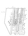
- FIG. 1 is a schematic overall sectional view of a connector according to an embodiment.
- FIG. 2 is an enlarged cross-sectional view of the main part A shown in FIG.
- FIG. 3 is a schematic overall cross-sectional perspective view of the connector according to the embodiment.
- the connector 1 includes a substantially box-shaped housing 2, a female terminal 3 inserted into the housing 2, and a bus bar 4 supported by the housing 2.
- the housing 2 includes a terminal accommodating chamber 5 in which the female terminal 3 is accommodated, a flexible locking arm 7 that can be bent in a direction orthogonal to the terminal insertion direction, and a guide wall 9 that supports the bus bar 4. .
- the terminal accommodating chamber 5 formed in the housing 2 has a space for accommodating the female terminal 3.
- the locking arm 7 has elasticity and is formed so as to protrude from one side of the housing 2.
- the locking arm 7 includes a first fixing portion 17 that fixes one end of the locking arm 7 to one side of the housing 2, and a second fixing portion 19 that connects the other end of the locking arm 7 to the guide wall 9.
- the arm part 21 which connects the 1st fixing
- the arm portion 21 connects the first fixing portion 17 and the second fixing portion 19.
- the arm portion 21 includes a thick portion 22 in which the arm portion 21 is thick, a thin portion 24 that is thinner than the thick portion 22, and a relationship formed between the thick portion 22 and the thin portion 24. And a stepped portion 26.
- the locking step 26 is provided with an inclined surface for locking the female terminal 3.
- the guide wall 9 is formed in the vicinity of the second fixing portion 19 and supports the bus bar 4.
- the guide wall 9 includes a guide portion 23 that holds and supports the bus bar 4, and a connecting portion 25 that is provided continuously to the guide portion 23.
- the connecting portion 25 is formed integrally with the second fixing portion 19, and is formed with a recess 29 that is provided so as to be recessed in the insertion direction of the female terminal 3.
- the female terminal 3 is inserted into the terminal accommodating chamber 5 of the housing 2.
- the female terminal 3 includes a main body 10 that is electrically connected to the bus bar 4 and a grip 12 that grips the electric wire W.
- the electric wire W includes a core wire 14 therein.
- the main body 10 is inserted in sliding contact with the inner wall of the terminal accommodating chamber 5.
- the main body 10 is formed by receiving a receiving wall 11 inserted into the inner wall of the terminal accommodating chamber 5, an elastic piece 13 formed by being folded inward from the receiving wall 11, and folded outward from the receiving wall 11. And a folded portion 16.
- the distal end portion 31 of the folded portion 16 is locked to a locking step portion 26 formed on the arm portion 21.
- the bus bar 4 as the male terminal portion 15 is supported so as to be inserted into the housing 2 from the side opposite to the direction in which the female terminal 3 is inserted and protrude into the terminal accommodating chamber 5.
- the bus bar 4 is press-fitted into the guide wall 9 from one side of the housing 2, and the bus bar 4 is supported by the guide wall 9. At this time, the bus bar 4 is press-fitted to a position protruding into the terminal accommodating chamber 5.
- the female terminal 3 is inserted into the terminal accommodating chamber 5 from the opening on the other side of the housing 2.
- the receiving wall 11 of the main body portion 10 is in sliding contact with the inner wall of the terminal accommodating chamber 5, and the tip end portion 31 of the folded portion 16 of the female terminal 3 is slidably contacting along the shape of the arm portion 21. Inserted inside.
- the folded portion 16 presses the arm portion 21 in a direction orthogonal to the insertion direction, thereby bending the arm portion 21.
- the female terminal 3 comes into contact with the one surface side 19a of the second fixing portion 19 to restrict the movement of the female terminal 3.
- the connecting portion 25 provided continuously with the guide wall 9 is formed integrally with the second fixing portion 19, and the distance between the first fixing portion 17 and the second fixing portion 19 is locked.
- the distance D2 is set so that the elastic force of the arm 7 becomes a desired elastic force. For this reason, after supporting the female terminal 3 reliably, the arm part 21 can be easily bent, so that the female terminal 3 can be easily inserted into the housing 2.
- the female terminal 3 can be inserted into the housing 2 more easily. be able to.
- the entire length of the arm portion 21 is formed from the first fixing portion 17 to the connecting portion 25 from the distance D1 from the first fixing portion 17 to the connecting portion end face 25a.
- the distance from the concave portion 29 to the bottom wall 29a can be set to the distance D2, and the distance from the connecting portion end face 25a to the bottom wall 29a of the concave portion 29 can be increased by the distance E.
- the connecting portion end surface 25a where the recess 29 is not formed is formed so as to be flush with the guide wall end surface 9a, the guide wall 9 supporting the bus bar 4 can be made as long as possible. Therefore, the arm portion 21 can be easily bent.
- the arm portion 21 bends in a direction perpendicular to the insertion direction, but the female terminal 3 abuts on the one surface side 19a of the second fixing portion 19, The movement of the female terminal 3 can be restricted, and damage and wear of the female terminal 3 due to vibration of the connector 1 can be prevented.
- the present invention can be used for a connector.
Landscapes
- Connector Housings Or Holding Contact Members (AREA)
- Details Of Connecting Devices For Male And Female Coupling (AREA)
Description
本発明は、コネクタに関し、特に端子と係合する可撓性の係止腕が両持ちのアーム部を有するコネクタに関するものである。
従来のコネクタとして、端子(雌端子)を収容する端子収容室と、端子収容室の内側面に設けられるとともに挿入された端子に対して弾性的に係止可能な可撓性のランス(係止腕)とが設けられ、このランスが、両端部が支持された両持ち状に形成されているとともに外部から解除治具にて操作可能な操作凹部を備えたものが特許文献1又は特許文献2で提案されている。
しかしながら、特許文献1,2で開示された従来のコネクタでは、端子収容室に端子を挿入する際、ランスの反力が高く、端子収容室への端子の強い挿入力が必要となっていた。そこで、端子を挿入する際のランスの反力を低くするために、相手端子(雄端子)を支持する前壁を薄くすることが考えられる。しかしながら、相手端子を支持する前壁を薄くすると相手端子を確実に支持することができずに、接触不良等を招く虞があった。
そこで、本発明は、端子を確実に支持することができ、かつ、端子収容室への端子の挿入を容易にすることのできるコネクタを提供することを目的としている。
本発明の第1の特徴に係るコネクタは、略箱状のハウジングと、ハウジング内に挿入される雌端子と、ハウジングに支持されるバスバーとを備える。ハウジングに、端子が収容される端子収容室と、弾性を有する可撓性の係止腕と、バスバーをハウジング内に案内する案内壁とを備える。係止腕は、係止腕の一端側を固定する第1固定部と、係止腕の他端側を固定する第2固定部と、第1固定部と第2固定部とを連結するアーム部とを備える。案内壁に連設して設けられる連結部が、第2固定部と一体に形成される。第1固定部と第2固定部との距離が、係止腕の弾性力が所望の弾性力となる距離に設定される。
端子案内壁に連設して設けられる連結部が第2固定部と一体に形成され、第1固定部と第2固定部との距離が係止腕の弾性力が所望の弾性力となる距離に設定されることにより、雌端子を確実に支持したうえで、アーム部を撓み易くすることができ、ハウジングへの雌端子の挿入を容易にすることができる。
連結部には、凹部が設けられていることが好ましい。
連結部に凹部を設けたことにより、第1固定部と第2固定部との距離をより長く確保することができるため、より容易にハウジングに雌端子を挿入することができる。
第2固定部によって雌端子の動きが規制されていることが好ましい。
第2固定部の一面側に雌端子が当接するため、雌端子の動きを規制することができ、コネクタの振動による雌端子の破損、摩耗を防止することができる。
以下、本発明の実施形態に係るコネクタ1ついて、図1―3を用いて詳細に説明する。
実施形態に係るコネクタ1は、略箱状のハウジング2と、ハウジング2内に挿入される雌端子3と、ハウジング2に支持されるバスバー4とを備える。
ハウジング2は、雌端子3が収容される端子収容室5と、端子の挿入方向に直交する方向に撓み可能な可撓性の係止腕7と、バスバー4を支持する案内壁9とを備える。
ハウジング2内に形成される端子収容室5は、雌端子3が収容されるスペースを有して形成されている。
係止腕7は、弾性を有し、ハウジング2の一辺から突出するように形成される。係止腕7は、係止腕7の一端側をハウジング2の一辺に固定する第1固定部17と、係止腕7の他端側を案内壁9に連設させる第2固定部19と、第1固定部17と第2固定部19とを連結するアーム部21とを備える。
アーム部21は、第1固定部17と第2固定部19とを連結する。アーム部21は、アーム部21の厚さが厚い厚肉部22と、厚肉部22の厚さと比べて薄い薄肉部24と、厚肉部22と薄肉部24との間に形成される係止段部26とを備える。係止段部26には、雌端子3を係止するための傾斜面が設けられている。
案内壁9は、第2固定部19の近傍に形成されて、バスバー4を支持する。案内壁9は、バスバー4を狭持して支持する案内部23と、案内部23に連設して設けられる連結部25とを備える。連結部25には、第2固定部19と一体に形成されるとともに、雌端子3の挿入方向に凹設して設けられる凹部29が形成されている。
ハウジング2の端子収容室5には、雌端子3が挿入される。雌端子3は、バスバー4に電気的に接続される本体部10と、電線Wを把持する把持部12とを備える。電線Wは、内部に芯線14を備える。
本体部10は、端子収容室5の内壁に摺接して挿入される。本体部10は、端子収容室5の内壁に挿入される受壁11と、受壁11から内方に折り返されて形成される弾性片13と、受壁11から外方に折り返されて形成される折返し部16とを備える。折返し部16の先端部31は、アーム部21に形成される係止段部26に係止される。
雄端子部15としてのバスバー4は、雌端子3が挿入される方向と反対側からハウジング2に挿入されて端子収容室5に突出するように支持されている。
次に、ハウジング2への雌端子3の取付方法について説明する。
まず、ハウジング2の一方側から案内壁9内にバスバー4を圧入し、案内壁9によってバスバー4を支持する。このとき、バスバー4は端子収容室5に突出する位置まで圧入される。
次に、ハウジング2の他方側の開口から端子収容室5へ雌端子3を挿入する。この際、本体部10の受壁11が端子収容室5の内壁に摺接するとともに、雌端子3の折返し部16の先端部31が、アーム部21の形状に沿って摺接しながら端子収容室5内に挿入される。そして、折返し部16がアーム部21を挿入方向と直交する方向に押圧し、アーム部21を撓ませる。アーム部21が撓んだ際に、雌端子3が第2固定部19の一面側19aに当接し、雌端子3の動きを規制している。
そして、折返し部16の先端部31が、ハウジング2の他方側から挿入されてアーム部21の厚肉部22を越えて係止段部26を越える。すると、アーム部21が弾性復帰するとともに、折返し部16の先端部31が係止段部26に係止される。こうして、ハウジング2への雌端子3の取り付けが完了する。
実施形態に係るコネクタ1では、案内壁9に連設して設けられる連結部25が第2固定部19と一体に形成され、第1固定部17と第2固定部19との距離を係止腕7の弾性力が所望の弾性力となる距離D2に設定する。このため、雌端子3を確実に支持したうえで、アーム部21を撓み易くすることができるため、ハウジング2への雌端子3の挿入を容易にすることができる。
また、連結部25に凹部29を設けたことにより、第1固定部17と第2固定部19との距離をより長く確保することができるため、より容易にハウジング2に雌端子3を挿入することができる。
すなわち、連結部25に凹部29を設けたことにより、アーム部21全体の長さを第1固定部17から連結部端面25aとの距離D1から、第1固定部17から連結部25に形成された凹部29の底壁29aまでの距離を距離D2にすることができ、連結部端面25aから凹部29の底壁29aまでの距離を距離E分だけ伸ばすことができる。
さらに、凹部29の形成されていない連結部端面25aは、案内壁端面9aと所謂面一に形成されているため、バスバー4を支持する案内壁9を出来るだけ長くすることができるとともに、凹部29を形成しているためアーム部21を撓みやすくすることができる。
加えて、雌端子3を端子収容室5内に挿入する際、アーム部21が挿入方向と直交する方向に撓むが、第2固定部19の一面側19aに雌端子3が当接するため、雌端子3の動きを規制することができ、コネクタ1の振動による雌端子3の破損、摩耗を防止することができる。
本発明は、コネクタに利用することができる。
Claims (3)
- コネクタであって、
略箱状のハウジングと、
前記ハウジング内に挿入される雌端子と、
前記ハウジングに支持されるバスバーと
を備え、
前記ハウジングは、
前記雌端子が収容される端子収容室と、
前記端子収容室内に設けられた弾性を有する可撓性の係止腕と、
前記バスバーをハウジング内に案内する案内壁と
を備え、
前記係止腕は、
前記係止腕の一端側を固定する第1固定部と、
前記係止腕の他端側を固定する第2固定部と、
前記第1固定部と前記第2固定部とを連結するアーム部と
を備え、
前記案内壁に連設して設けられる連結部が、前記第2固定部と一体に形成され、
前記第1固定部と前記第2固定部との距離が、前記係止腕の弾性力が所望の弾性力となる距離に設定される
ことを特徴とするコネクタ。 - 請求項1記載のコネクタであって、前記連結部には、凹部が設けられることを特徴とするコネクタ。
- 請求項1または2に記載のコネクタであって、前記第2固定部によって前記雌端子の動きが規制されていることを特徴とするコネクタ。
Priority Applications (2)
| Application Number | Priority Date | Filing Date | Title |
|---|---|---|---|
| CN201380049178.9A CN104662742B (zh) | 2012-09-21 | 2013-09-11 | 连接器 |
| US14/661,127 US9318827B2 (en) | 2012-09-21 | 2015-03-18 | Connector |
Applications Claiming Priority (2)
| Application Number | Priority Date | Filing Date | Title |
|---|---|---|---|
| JP2012207779A JP6141612B2 (ja) | 2012-09-21 | 2012-09-21 | コネクタ |
| JP2012-207779 | 2012-09-21 |
Related Child Applications (1)
| Application Number | Title | Priority Date | Filing Date |
|---|---|---|---|
| US14/661,127 Continuation US9318827B2 (en) | 2012-09-21 | 2015-03-18 | Connector |
Publications (1)
| Publication Number | Publication Date |
|---|---|
| WO2014045957A1 true WO2014045957A1 (ja) | 2014-03-27 |
Family
ID=50341271
Family Applications (1)
| Application Number | Title | Priority Date | Filing Date |
|---|---|---|---|
| PCT/JP2013/074485 Ceased WO2014045957A1 (ja) | 2012-09-21 | 2013-09-11 | コネクタ |
Country Status (4)
| Country | Link |
|---|---|
| US (1) | US9318827B2 (ja) |
| JP (1) | JP6141612B2 (ja) |
| CN (1) | CN104662742B (ja) |
| WO (1) | WO2014045957A1 (ja) |
Cited By (1)
| Publication number | Priority date | Publication date | Assignee | Title |
|---|---|---|---|---|
| JP2017199541A (ja) * | 2016-04-27 | 2017-11-02 | 第一精工株式会社 | 端子及びコネクタ |
Families Citing this family (11)
| Publication number | Priority date | Publication date | Assignee | Title |
|---|---|---|---|---|
| JP6141612B2 (ja) * | 2012-09-21 | 2017-06-07 | 矢崎総業株式会社 | コネクタ |
| DE102014202316B4 (de) * | 2014-02-07 | 2021-04-01 | Te Connectivity Germany Gmbh | Kontaktträger mit einem Grundkörper und wenigstens einem Kontaktelement, Werkzeug zum Spritzgießen eines Kontaktträgers und Verfahren zur Herstellung eines Kontaktträgers |
| JP6276113B2 (ja) * | 2014-06-02 | 2018-02-07 | ホシデン株式会社 | コネクタ |
| JP6206392B2 (ja) * | 2014-12-25 | 2017-10-04 | 株式会社オートネットワーク技術研究所 | ジョイントコネクタ |
| KR101755856B1 (ko) * | 2015-10-06 | 2017-07-19 | 현대자동차주식회사 | 차량용 다중 접지 커넥터 |
| JP6915858B2 (ja) * | 2017-08-08 | 2021-08-04 | 日本圧着端子製造株式会社 | コネクタ |
| JP7259444B2 (ja) * | 2019-03-20 | 2023-04-18 | 住友電装株式会社 | コネクタ |
| KR102805462B1 (ko) * | 2019-12-04 | 2025-05-09 | 현대자동차주식회사 | 커넥터와 센서 유닛의 결합체 |
| DE102020204456A1 (de) * | 2020-04-07 | 2021-10-07 | Te Connectivity Germany Gmbh | Verbindungsanordnung |
| JP7480718B2 (ja) * | 2021-01-25 | 2024-05-10 | 住友電装株式会社 | コネクタ |
| JP7448959B2 (ja) * | 2021-03-26 | 2024-03-13 | 北川工業株式会社 | コネクタ |
Citations (2)
| Publication number | Priority date | Publication date | Assignee | Title |
|---|---|---|---|---|
| JP2012084405A (ja) * | 2010-10-12 | 2012-04-26 | Yazaki Corp | コネクタ |
| JP2012134010A (ja) * | 2010-12-21 | 2012-07-12 | Yazaki Corp | コネクタ |
Family Cites Families (56)
| Publication number | Priority date | Publication date | Assignee | Title |
|---|---|---|---|---|
| FR2650707B1 (fr) * | 1989-08-07 | 1991-10-11 | Labinal | Dispositif de shuntage pour faisceaux de conducteurs electriques |
| US5201667A (en) * | 1990-06-27 | 1993-04-13 | Yazaki Corporation | Branch circuit structure |
| JP2903918B2 (ja) * | 1992-12-09 | 1999-06-14 | 住友電装株式会社 | ジョイントコネクタ |
| US5403204A (en) * | 1993-03-03 | 1995-04-04 | Sumitomo Wiring Systems, Ltd. | Joint connector |
| US5788519A (en) * | 1995-05-02 | 1998-08-04 | Yazaki Corporation | Waterproof grounding connector and method of assembling same |
| JP2910623B2 (ja) * | 1995-06-06 | 1999-06-23 | 住友電装株式会社 | ジョイントコネクタ、端子金具及びコネクタハウジング |
| US5769650A (en) * | 1995-06-19 | 1998-06-23 | Sumitomo Wiring Systems, Ltd. | Connector and cover therefor |
| EP1030411A1 (en) * | 1999-02-16 | 2000-08-23 | Sumitomo Wiring Systems, Ltd. | A joint connector |
| DE60027953T2 (de) * | 1999-04-13 | 2007-04-19 | Sumitomo Wiring Systems, Ltd., Yokkaichi | Wasserdichter Verbinder für elektrische Anschlusskontakte |
| JP3754304B2 (ja) * | 2001-02-16 | 2006-03-08 | 矢崎総業株式会社 | ジョイントコネクタ |
| JP3804489B2 (ja) | 2001-08-10 | 2006-08-02 | 住友電装株式会社 | コネクタ |
| DE60237175D1 (de) * | 2001-06-18 | 2010-09-09 | Sumitomo Wiring Systems | Steckverbinder und Entsperrvorrichtung dafür |
| JP2003059584A (ja) * | 2001-08-17 | 2003-02-28 | Yazaki Corp | コネクタとコネクタハウジング |
| JP3985630B2 (ja) * | 2002-08-19 | 2007-10-03 | 住友電装株式会社 | 電気接続箱および該電気接続箱の組立方法 |
| US7354318B2 (en) * | 2002-09-19 | 2008-04-08 | The Furukawa Electric Co., Ltd. | Joint connector |
| JP2004179032A (ja) * | 2002-11-28 | 2004-06-24 | Sumitomo Wiring Syst Ltd | ジョイントコネクタ |
| JP3944070B2 (ja) * | 2002-12-12 | 2007-07-11 | 住友電装株式会社 | アースジョイントコネクタ |
| JP2005019282A (ja) * | 2003-06-27 | 2005-01-20 | Sumitomo Wiring Syst Ltd | コネクタ |
| DE102004034396B4 (de) * | 2003-07-17 | 2011-12-22 | Autonetworks Technologies, Ltd. | Verbindungsteil und Verbindungsstecker für einen Kabelbaum |
| JP2005158418A (ja) | 2003-11-25 | 2005-06-16 | Sumitomo Wiring Syst Ltd | コネクタ |
| JP2005346940A (ja) * | 2004-05-31 | 2005-12-15 | Yazaki Corp | ジョイントコネクタ構造 |
| JP4259453B2 (ja) * | 2004-10-29 | 2009-04-30 | 住友電装株式会社 | 防水コネクタ |
| JP2006253017A (ja) * | 2005-03-11 | 2006-09-21 | Sumitomo Wiring Syst Ltd | ジョイントコネクタ |
| JP4508098B2 (ja) * | 2005-12-20 | 2010-07-21 | 住友電装株式会社 | コネクタ |
| US7332674B2 (en) * | 2006-04-19 | 2008-02-19 | Delphi Technologies, Inc. | Electrical splice assembly |
| US7396255B2 (en) * | 2006-09-19 | 2008-07-08 | Delphi Technologies, Inc. | Electrical connector |
| US7384309B1 (en) * | 2007-01-18 | 2008-06-10 | Delphi Technologies, Inc. | Electrical connector body having cantilevered terminal hold-down beams |
| JP5140407B2 (ja) * | 2007-12-18 | 2013-02-06 | 株式会社オートネットワーク技術研究所 | ジョイントコネクタ |
| JP2010040508A (ja) * | 2008-07-08 | 2010-02-18 | Sumitomo Wiring Syst Ltd | コネクタおよびワイヤハーネス |
| JP5176803B2 (ja) * | 2008-09-11 | 2013-04-03 | 住友電装株式会社 | ジョイントコネクタおよびジョイントコネクタ付きワイヤハーネス |
| JP5267162B2 (ja) * | 2009-01-29 | 2013-08-21 | 株式会社オートネットワーク技術研究所 | 防水ジョイントコネクタ |
| JP5428674B2 (ja) * | 2009-09-08 | 2014-02-26 | 株式会社オートネットワーク技術研究所 | アース接続装置及びこれを含むワイヤハーネス |
| JP5370767B2 (ja) * | 2009-11-10 | 2013-12-18 | 住友電装株式会社 | ジョイントコネクタ及びワイヤハーネス |
| JP5233962B2 (ja) * | 2009-11-10 | 2013-07-10 | 住友電装株式会社 | ジョイントコネクタ及びワイヤハーネス |
| US7980872B1 (en) * | 2010-03-15 | 2011-07-19 | Delphi Technologies, Inc. | Splice assembly |
| CN102834987B (zh) * | 2010-03-25 | 2015-04-15 | 矢崎总业株式会社 | 接头连接器和用于识别接头连接器中的汇流条图案的方法 |
| JP2012169186A (ja) * | 2011-02-15 | 2012-09-06 | Yazaki Corp | ジョイントコネクタ |
| JP2012169185A (ja) * | 2011-02-15 | 2012-09-06 | Yazaki Corp | ジョイントコネクタ装置 |
| JP2012174431A (ja) * | 2011-02-18 | 2012-09-10 | Yazaki Corp | ジョイントコネクタ及び端子半挿入検査方法 |
| JP2012174432A (ja) * | 2011-02-18 | 2012-09-10 | Yazaki Corp | ジョイントコネクタ |
| US8257111B1 (en) * | 2011-03-03 | 2012-09-04 | Delphi Technologies, Inc. | Sealed electrical splice assembly |
| JP2012186115A (ja) * | 2011-03-08 | 2012-09-27 | Yazaki Corp | コネクタ |
| JP2012199190A (ja) * | 2011-03-23 | 2012-10-18 | Yazaki Corp | コネクタ |
| JP5704025B2 (ja) * | 2011-09-08 | 2015-04-22 | 株式会社オートネットワーク技術研究所 | ジョイントコネクタ |
| JP5668655B2 (ja) * | 2011-09-20 | 2015-02-12 | 株式会社オートネットワーク技術研究所 | 導電板およびジョイントコネクタ |
| US9362665B2 (en) * | 2011-09-29 | 2016-06-07 | Autonetworks Technologies, Ltd. | Joint connector with pairs of locking lances and communication space extending between the pairs of locking lances |
| JP2014002846A (ja) * | 2012-06-15 | 2014-01-09 | Yazaki Corp | ジョイントコネクタ拡張構造およびジョイントコネクタ |
| JP2014011148A (ja) * | 2012-07-03 | 2014-01-20 | Yazaki Corp | コネクタ |
| JP6235199B2 (ja) * | 2012-08-02 | 2017-11-22 | 矢崎総業株式会社 | コネクタ |
| JP6141612B2 (ja) * | 2012-09-21 | 2017-06-07 | 矢崎総業株式会社 | コネクタ |
| JP5783468B2 (ja) * | 2012-10-29 | 2015-09-24 | 住友電装株式会社 | コネクタ |
| JP2014093222A (ja) * | 2012-11-05 | 2014-05-19 | Sumitomo Wiring Syst Ltd | コネクタ |
| JP5772810B2 (ja) * | 2012-12-27 | 2015-09-02 | 住友電装株式会社 | ジョイントコネクタ |
| US8992251B2 (en) * | 2013-03-19 | 2015-03-31 | Delphi Technologies, Inc. | Electrical splice assembly |
| JP5708705B2 (ja) * | 2013-05-20 | 2015-04-30 | 第一精工株式会社 | 電気コネクタ |
| JP5708837B1 (ja) * | 2014-02-06 | 2015-04-30 | 第一精工株式会社 | コネクタ端子 |
-
2012
- 2012-09-21 JP JP2012207779A patent/JP6141612B2/ja active Active
-
2013
- 2013-09-11 CN CN201380049178.9A patent/CN104662742B/zh active Active
- 2013-09-11 WO PCT/JP2013/074485 patent/WO2014045957A1/ja not_active Ceased
-
2015
- 2015-03-18 US US14/661,127 patent/US9318827B2/en active Active
Patent Citations (2)
| Publication number | Priority date | Publication date | Assignee | Title |
|---|---|---|---|---|
| JP2012084405A (ja) * | 2010-10-12 | 2012-04-26 | Yazaki Corp | コネクタ |
| JP2012134010A (ja) * | 2010-12-21 | 2012-07-12 | Yazaki Corp | コネクタ |
Cited By (2)
| Publication number | Priority date | Publication date | Assignee | Title |
|---|---|---|---|---|
| JP2017199541A (ja) * | 2016-04-27 | 2017-11-02 | 第一精工株式会社 | 端子及びコネクタ |
| US9905955B2 (en) | 2016-04-27 | 2018-02-27 | Dai-Ichi Seiko Co., Ltd. | Terminal and connector |
Also Published As
| Publication number | Publication date |
|---|---|
| US9318827B2 (en) | 2016-04-19 |
| JP2014063630A (ja) | 2014-04-10 |
| CN104662742A (zh) | 2015-05-27 |
| US20150194757A1 (en) | 2015-07-09 |
| JP6141612B2 (ja) | 2017-06-07 |
| CN104662742B (zh) | 2017-10-24 |
Similar Documents
| Publication | Publication Date | Title |
|---|---|---|
| JP6141612B2 (ja) | コネクタ | |
| CN103457084B (zh) | 连接器 | |
| JP6088472B2 (ja) | コネクタ | |
| CN105406243B (zh) | 电连接器 | |
| JP2014053205A (ja) | メス端子、及び、それを用いたコネクタ | |
| JP5753416B2 (ja) | コネクタ端子 | |
| WO2012128283A1 (ja) | コネクタ | |
| WO2014084025A1 (ja) | 端子抜き治具 | |
| EP3879637B1 (en) | Connector lock structure | |
| WO2012111572A1 (ja) | コネクタ及び該コネクタの組立用治具 | |
| JP5626118B2 (ja) | コネクタ | |
| JP5272934B2 (ja) | コネクタ | |
| JP2006236678A (ja) | コネクタ | |
| JP5052373B2 (ja) | コネクタ | |
| CN101227041A (zh) | 连接器的锁定机构 | |
| JP2018014300A (ja) | コネクタ | |
| JP6506904B2 (ja) | コネクタ | |
| CN103022779B (zh) | 连接器 | |
| JP2011018522A (ja) | コネクタ | |
| WO2015056637A1 (ja) | コネクタ、コネクタのハウジングおよびコネクタの端子 | |
| JP6100117B2 (ja) | コネクタ | |
| JP2007280729A (ja) | 雌端子金具 | |
| JP2014137866A (ja) | コネクタ | |
| JP2015090731A (ja) | コネクタ | |
| JP5314535B2 (ja) | コネクタ |
Legal Events
| Date | Code | Title | Description |
|---|---|---|---|
| 121 | Ep: the epo has been informed by wipo that ep was designated in this application |
Ref document number: 13838832 Country of ref document: EP Kind code of ref document: A1 |
|
| NENP | Non-entry into the national phase |
Ref country code: DE |
|
| 122 | Ep: pct application non-entry in european phase |
Ref document number: 13838832 Country of ref document: EP Kind code of ref document: A1 |