WO2014024646A1 - Dispositif d'enroulement et procédé de liaison d'un matériau de fil à une borne - Google Patents
Dispositif d'enroulement et procédé de liaison d'un matériau de fil à une borne Download PDFInfo
- Publication number
- WO2014024646A1 WO2014024646A1 PCT/JP2013/069279 JP2013069279W WO2014024646A1 WO 2014024646 A1 WO2014024646 A1 WO 2014024646A1 JP 2013069279 W JP2013069279 W JP 2013069279W WO 2014024646 A1 WO2014024646 A1 WO 2014024646A1
- Authority
- WO
- WIPO (PCT)
- Prior art keywords
- terminal
- wire
- wound
- winding
- around
- Prior art date
Links
Images


Classifications
-
- H—ELECTRICITY
- H01—ELECTRIC ELEMENTS
- H01F—MAGNETS; INDUCTANCES; TRANSFORMERS; SELECTION OF MATERIALS FOR THEIR MAGNETIC PROPERTIES
- H01F41/00—Apparatus or processes specially adapted for manufacturing or assembling magnets, inductances or transformers; Apparatus or processes specially adapted for manufacturing materials characterised by their magnetic properties
- H01F41/02—Apparatus or processes specially adapted for manufacturing or assembling magnets, inductances or transformers; Apparatus or processes specially adapted for manufacturing materials characterised by their magnetic properties for manufacturing cores, coils, or magnets
- H01F41/04—Apparatus or processes specially adapted for manufacturing or assembling magnets, inductances or transformers; Apparatus or processes specially adapted for manufacturing materials characterised by their magnetic properties for manufacturing cores, coils, or magnets for manufacturing coils
- H01F41/06—Coil winding
- H01F41/076—Forming taps or terminals while winding, e.g. by wrapping or soldering the wire onto pins, or by directly forming terminals from the wire
-
- H—ELECTRICITY
- H01—ELECTRIC ELEMENTS
- H01F—MAGNETS; INDUCTANCES; TRANSFORMERS; SELECTION OF MATERIALS FOR THEIR MAGNETIC PROPERTIES
- H01F41/00—Apparatus or processes specially adapted for manufacturing or assembling magnets, inductances or transformers; Apparatus or processes specially adapted for manufacturing materials characterised by their magnetic properties
- H01F41/02—Apparatus or processes specially adapted for manufacturing or assembling magnets, inductances or transformers; Apparatus or processes specially adapted for manufacturing materials characterised by their magnetic properties for manufacturing cores, coils, or magnets
- H01F41/04—Apparatus or processes specially adapted for manufacturing or assembling magnets, inductances or transformers; Apparatus or processes specially adapted for manufacturing materials characterised by their magnetic properties for manufacturing cores, coils, or magnets for manufacturing coils
- H01F41/06—Coil winding
- H01F41/098—Mandrels; Formers
-
- H—ELECTRICITY
- H01—ELECTRIC ELEMENTS
- H01R—ELECTRICALLY-CONDUCTIVE CONNECTIONS; STRUCTURAL ASSOCIATIONS OF A PLURALITY OF MUTUALLY-INSULATED ELECTRICAL CONNECTING ELEMENTS; COUPLING DEVICES; CURRENT COLLECTORS
- H01R43/00—Apparatus or processes specially adapted for manufacturing, assembling, maintaining, or repairing of line connectors or current collectors or for joining electric conductors
- H01R43/033—Apparatus or processes specially adapted for manufacturing, assembling, maintaining, or repairing of line connectors or current collectors or for joining electric conductors for wrapping or unwrapping wire connections
Definitions
- the present invention relates to a winding device for binding an end portion of a wire wound around a wound member having a terminal to the terminal and a method for binding the wire wound around the wound member to the terminal. It is.
- JP 7-283065A discloses a winding device for winding a wire supplied from a nozzle under a predetermined tension around a rotating member to be wound.
- a wire is wound around a terminal provided on the member to be wound before and after winding.
- the wire entangled with the terminal is cut with a cutter, etc., but since tension is always applied to the wire, it is necessary to hold the wire between the nozzle and the cutting part so that the wire does not come out of the nozzle by cutting. is there. Therefore, in such a winding machine, a binding member for temporarily binding the wire is provided.
- the wire is first wound around the binding member, and the nozzle moves around the terminal in this state, so that the wire fed from the nozzle becomes the terminal. Tangle it. Thereafter, the wire from the binding member to the terminal is cut in the vicinity of the terminal. At the end of winding, the nozzle is led from the winding body of the member to be wound to the vicinity of the terminal, and the nozzle is turned around the terminal, whereby the wire fed from the nozzle is entangled with the terminal. Thereafter, the wire extending from the terminal to the nozzle side is cut in the vicinity of the terminal, whereby the wire is wound around the member to be wound having the terminal, and the coil in which the end of the wire is entangled with the terminal is obtained.
- a coil may be manufactured using a wire having a large diameter with respect to the size of the member to be wound.
- a relatively small coil is manufactured using a wire with a large diameter
- a relatively large force acts on the terminal provided on the member to be wound due to the rigidity of the wire with a large diameter.
- the terminal provided on the member to be wound is inclined, and the member to be wound to which the terminal is attached is damaged, or the terminal itself is bent so that the terminal is bent.
- the present invention relates to a winding device that can reliably tie a wire to a terminal without damaging a member to be wound or the terminal itself, even if the wire has a relatively large diameter, and a wire to the terminal of the wire.
- the purpose is to provide a bald method.
- a winding device capable of gripping a wound member having a body portion around which the wire is wound and a terminal for winding the wire, and facing the wound member
- the wire that feeds the wire, the binding member that locks the end of the wire fed from the nozzle, and the wire that is fed from the nozzle is wound around the wound member by rotating the chuck together with the binding member.
- a winding mechanism, a wire cutting mechanism that cuts the wire wound around the wound member, and a wire rod that winds the end of the wire wound around the wound member and cut by the wire cutting mechanism around the terminal A bald mechanism.
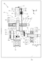
- FIG. 1A is a front view of a winding device according to an embodiment of the present invention.
- FIG. 1B is an enlarged view of a portion B in FIG. 1A.
- FIG. 1C is an enlarged view of a portion C in FIG. 1A.
- FIG. 2 is a top view of the winding device according to the embodiment of the present invention.
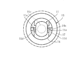
- 3 is a cross-sectional view taken along line AA in FIG. 1A.
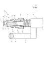
- FIG. 4 is a perspective view showing a member to be wound and a chuck that supports the member to be wound.
- FIG. 5 is a perspective view showing a state in which the member to be wound is supported by the chuck.
- FIG. 1A is a front view of a winding device according to an embodiment of the present invention.
- FIG. 1B is an enlarged view of a portion B in FIG. 1A.
- FIG. 1C is an enlarged view of a portion C in FIG. 1A.
- FIG. 2 is a top view of the
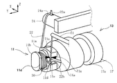
- FIG. 6 is a perspective view showing a state in which the wire at the beginning of winding is locked to the terminal of the member to be wound.
- FIG. 7 is a perspective view showing a state in which a wire is wound around the member to be wound.
- FIG. 8 is a perspective view showing a state in which the wire material at the end of winding is locked to the terminal of the member to be wound.
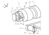
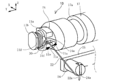
- FIG. 9 is a perspective view showing a state where the terminal of the member to be wound is opposed to the cylindrical member.
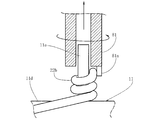
- FIG. 10 is an enlarged cross-sectional view showing a state where the terminal is inserted into the cylindrical member.
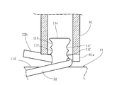
- FIG. 11 is an enlarged cross-sectional view illustrating a state in which the wire member at the end of winding is wound around the terminal by rotating the cylindrical member in which the terminal is inserted.
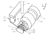
- FIG. 12 is a perspective view showing a state in which the wire material at the beginning of winding, which is locked to the terminal of the member to be wound, is cut.
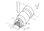
- FIG. 13 is a perspective view showing a state in which a terminal at which the wire at the beginning of winding is locked is made to face a cylindrical member.
- FIG. 14 is an enlarged cross-sectional view showing a state where the terminal is inserted into the cylindrical member.
- FIG. 15 is an enlarged cross-sectional view showing a state in which the wire member at the beginning of winding is wound around the terminal by rotating the cylindrical member in which the terminal is inserted.
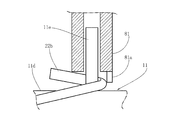
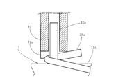
- FIG. 16 is an enlarged cross-sectional view showing a state where a plate-like terminal is inserted into a cylindrical member.
- FIG. 17 is an enlarged cross-sectional view showing a state in which a tubular member having a plate-like terminal inserted therein is rotated and the wire material at the beginning of winding is wound around the terminal.
- FIG. 1A is a diagram showing a winding device according to an embodiment of the present invention.
- three axes of X, Y, and Z orthogonal to each other are set, and the winding according to the embodiment of the present invention assumes that the X axis extends in the horizontal front-rear direction, the Y axis extends in the horizontal horizontal direction, and the Z axis extends in the vertical direction.
- the apparatus 10 will be described.
- the winding device 10 according to this embodiment includes a chuck 13 on which a member to be wound 11 around which a wire is wound can be mounted. As shown in FIGS.
- the member to be wound 11 is formed of an insulating material such as a dielectric, a magnetic material, insulator ceramics, plastics, and the like.
- 11b is a so-called chip component core.
- the winding body 11c of the member to be wound 11 has a circular cross section.
- the flange portions 11a and 11b at both ends of the member to be wound 11 have a circular outer shape, and are formed with flat portions 11d parallel to each other so as to face each other. Terminals 11e are provided on the flat surface portions 11d of the one flange portion 11a which are parallel to each other so as to protrude outwardly, and the terminals 11e are not provided on the other flange portion 11b.
- the chuck 13 grips one of the flange portions 11 a of the member to be wound 11.
- the chuck 13 is provided at the end of the spindle 12 that extends in the Y-axis direction and is disposed horizontally.
- the chuck 13 is fitted to the chuck body 14 provided at the tip of the spindle 12 so that the base end thereof is coaxial with the spindle 12 and the outer periphery of the chuck body 14, and is elastically supported in the axial direction by the chuck spring 16.
- a chuck opening and closing member 17 As shown in FIGS. 3 and 4, the chuck body 14 is formed with a slit 14 a extending in the axial direction from the tip along the central axis.
- the tip of the chuck body 14 is divided into two by the slits 14a, and a tapered surface 14c whose outer diameter decreases toward the spindle 12 is formed on the outer periphery of each divided piece.
- a recessed portion 14 d that accommodates one flange 11 a of the member to be wound 11 is formed around the slit 14 a at the front end edge of the chuck body 14.
- the peripheral wall of the recess 14d is formed in accordance with the outer shape of the one flange 11a.
- the chuck opening / closing member 17 fitted to the outer periphery of the chuck body 14 is a cylindrical member, and the inner periphery is configured to be in sliding contact with the tapered surface 14 c of each divided piece in the chuck body 14.
- the chuck opening / closing member 17 urged in the direction away from the spindle 12 by the chuck spring 16 presses the tapered surface 14c of the chuck body 14 in the same direction.
- the distance between the divided pieces at the tip of the chuck body 14 divided by the slit 14b is narrowed, so that one of the flanges 11a of the member to be wound 11 accommodated in the recess 14d at the tip is gripped. Further, as shown in FIG. 5, one flange 11 a of the member to be wound 11 is gripped in a state in which the center axis of the member to be wound 11 is aligned with the center axis of the chuck 13.
- the spindle 12 with the chuck 13 provided at the tip is provided with a binding member 24 that temporarily locks the end of the wire 22 fed from a nozzle 51 described later (see FIG. 5).
- the wire 22 in the present embodiment is an insulation coated conductor, and includes a conductor made of Cu and an insulation coating formed so as to cover the outer peripheral surface of the conductor.
- the binding member 24 is formed in a cylindrical shape, and a groove 24a is formed at the tip of the binding member 24 in the diameter direction and having a width that allows the wire rod 22a at the beginning of winding to enter.
- the binding member 24 is provided on the spindle 12 via an L-shaped attachment member 25.
- the spindle 12 is provided with a chuck 13 coaxially at its tip, and is pivotally supported by the base 18 so as to be rotatable about its central axis.
- the base 18 on which the spindle 12 is pivotally supported is fixed to the base 10a.
- a servo motor 27 is attached to the base 18 as a winding mechanism that rotates the spindle 12 together with the binding member 24.
- Pulleys 28a and 28b are provided on the spindle 12 and the rotary shaft 27a of the servomotor 27, respectively, and a belt 28c is installed on the pulleys 28a and 28b.
- the servomotor 27 is driven to rotate the rotating shaft 27a, the rotation is transmitted to the spindle 12 via the belt 28c.
- the spindle 12 rotates with the binding member 24.
- the base 10a is provided with a chuck opening / closing mechanism for operating the chuck 13.
- a wire rod feeding machine 50 for feeding the wire rod 22 is provided on the base 10a.
- the wire feeder 50 includes a nozzle 51 through which the wire 22 is inserted, a nozzle moving mechanism 52 that moves the nozzle 51 in three axial directions, and a tension device 53 that applies tension to the wire 22.
- the nozzle 51 is fixed to the support plate 54.
- the nozzle moving mechanism 52 is configured to be able to move the support plate 54 in three axial directions with respect to the base 10a.
- the nozzle moving mechanism 52 in the present embodiment is configured by a combination of X-axis, Y-axis, and Z-axis direction extendable actuators 56, 58, 57.
- the telescopic actuators 56 to 58 constituting the nozzle moving mechanism 52 are elongated box-shaped housings 56d to 58d and a ball screw 56b which is provided extending in the longitudinal direction inside the housings 56d to 58d and is rotationally driven by servo motors 56a to 58a.
- followers 56c to 58c and the like which are screwed into the ball screws 56b to 58b to move in parallel.
- the support plate 54 on which the nozzle 51 is provided is attached to the housing 56d of the X-axis direction extendable actuator 56 so that it can move in the X-axis direction.
- the follower 56c of the X-axis direction extendable actuator 56 is attached to the follower 57c of the Z-axis direction extendable actuator 57 so that the support plate 54 can move in the Z-axis direction together with the X-axis direction extendable actuator 56.
- the housing 57d of the Z-axis direction expansion / contraction actuator 57 is attached to the follower 58c of the Y-axis direction expansion / contraction actuator 58 so that the support plate 54 can move in the Y-axis direction together with the X-axis and Z-axis direction expansion / contraction actuators 56, 57. .
- the housing 58d of the Y-axis direction extendable actuator 58 extends in the Y-axis direction and is fixed to the pedestal 10a.
- the servo motors 56a to 58a in the telescopic actuators 56 to 58 are connected to control outputs of a controller (not shown) that controls them.
- the tension device 53 is capable of applying tension to the fed wire 22 and pulling back the wire 22.
- the tension device 53 includes a casing 61 provided on the base 10a, and a drum 62 and a tension bar 63 provided on a side surface of the casing 61 in the Y-axis direction.
- the wire rod 22 is wound around the drum 62, and a feeding control motor 64 that rotates the drum 62 to feed the wire rod 22 is provided inside the casing 61.
- the wire rod 22 fed out from the drum 62 is guided to a wire rod guide 63 a provided at the tip of the tension bar 63.
- the wire 22 guided to the wire guide 63a is wired so as to penetrate the nozzle 51 from the wire guide 63a.
- the tension bar 63 can be rotated in the X-axis direction with the rotation shaft 63b at the proximal end as a fulcrum.
- the rotation angle of the rotation shaft 63b is detected by a potentiometer 65 as a rotation angle detection mechanism housed in the casing 61 and attached to the rotation shaft 63b.
- the detection output of the potentiometer 65 is input to a controller (not shown), and the control output from the controller is connected to the feeding control motor 64.
- a spring 66 as an urging mechanism is attached to a predetermined position between the rotation shaft 63b of the tension bar 63 and the wire guide 63a.
- the spring 66 is an elastic member that applies a biasing force in the rotation direction of the tension bar 63, and one end of the spring 66 is attached between the rotation shaft 63b and the wire guide 63a via the attachment bracket 63c. For this reason, the tension bar 63 is given an elastic force according to the rotation angle by the spring 66 which is an elastic member. The other end of the spring 66 is fixed to the moving member 67.
- the moving member 67 is screwed into the male screw 68a of the tension adjusting screw 68, and is configured so that the movement can be adjusted according to the rotation of the male screw 68a. In this manner, the tension of the wire 22 applied by the tension bar 63 can be adjusted by displacing the fixing position of the other end of the spring 66.
- a controller (not shown) controls the feeding control motor 64 so that the rotation angle detected by the potentiometer 65 serving as a rotation angle detection mechanism becomes a predetermined angle. Therefore, in the tension device 53, tension is applied to the wire 22 by the spring 66 via the tension bar 63, and the drum 62 rotates so that the tension bar 63 is at a predetermined angle, and a predetermined amount of the wire 22 is fed out. . In this way, the tension of the wire 22 is maintained at a predetermined value.
- a nipper clamp device 71 for cutting the wire 22 that has passed through the nozzle 51 by air pressure is attached to the pedestal 10 a via the cutter moving mechanism 72. It is done.
- the nipper clamp device 71 cuts the wire 22 and holds one side of the cut wire 22 and is attached to the mounting plate 70.
- the cutter moving mechanism 72 that moves the nipper clamp device 71 is configured by a combination of X-axis, Y-axis, and Z-axis direction expansion / contraction actuators 73 to 75, similarly to the nozzle movement mechanism 52 described above.
- the attachment plate 70 on which the nipper clamp device 71 is provided is attached to the housing 73d of the Y-axis direction extendable actuator 73 so that it can move in the Y-axis direction.
- the follower 73 c of the Y-axis direction extendable actuator 73 is attached to the follower 74 c of the Z-axis direction extendable actuator 74 so that the mounting plate 70 can move in the Z-axis direction together with the Y-axis direction extendable actuator 73.
- the housing 74 d of the Z-axis direction extension / contraction actuator 74 is attached to the follower 75 c of the X-axis direction extension / contraction actuator 75 so that the attachment plate 70 can move in the X-axis direction together with the Y and Z-axis direction extension / contraction actuators 73 and 74.
- the housing 75d of the X-axis direction extendable actuator 75 extends in the X-axis direction and is fixed to the pedestal 10a.
- the servo motors 73a to 75a in each of the telescopic actuators 73 to 75 are connected to control outputs of a controller (not shown) that controls them.
- the cutter moving mechanism 72 is configured to be able to move the nipper clamp device 71 in three axial directions with respect to the base 10a.
- the nipper clamp device 71 is configured to be movable between a cutting position where the cutter teeth 71 a cut the wire 22 and a standby position where the cutter tooth 71 a is separated from the wire 22. Then, the cutter moving mechanism 72 moves the nipper clamp device 71 independently of the nozzle 51 and can be controlled by a controller (not shown).
- the winding device 10 is wound around a member 11 to be wound and has a wire rod entangled with a terminal 11e at an end portion of the wire rod 22 cut by a nipper clamp device 71 which is a wire rod cutting mechanism.
- a bald mechanism 80 is provided.
- the wire binding mechanism 80 includes a cylindrical member 81 into which the terminal 11e can be inserted, and a binding servo motor 82 that is a rotation mechanism that rotates the cylindrical member 81 around the terminal 11e.
- a column 79 is erected on the base 10 a in the vicinity of the base 18.
- a servo motor 82 is entangled via a motor moving mechanism 83 at the upper part of the column 79 so that the rotating shaft 82a faces downward in the vertical direction. Similar to the nozzle moving mechanism 52 and the cutter moving mechanism 72 described above, the motor moving mechanism 83 is configured by a combination of X-axis, Y-axis, and Z-axis direction expansion / contraction actuators 84 to 86.
- the attachment piece 87 provided with the binding servo motor 82 is attached to the housing 84d of the Z-axis direction extendable actuator 84 so as to be movable in the Z-axis direction.
- the follower 84c of the Z-axis direction extension / contraction actuator 84 is attached to the housing 85d of the X-axis direction extension / contraction actuator 85 via the angle member 88 so that the attachment piece 87 can move in the X-axis direction together with the Z-axis direction extension / contraction actuator 84.
- the follower 85c of the X-axis direction extendable actuator 85 is attached to the follower 86c of the Y-axis direction extendable actuator 86 so that the attachment piece 87 can move in the Y-axis direction together with the Z and X-axis direction extendable actuators 84 and 85. .
- the housing 86 d of the Y-axis direction extendable actuator 86 extends in the Y-axis direction and is fixed to the upper portion of the column 79.
- the servo motors 84a to 86a in the telescopic actuators 84 to 86 are connected to control outputs of a controller (not shown) that controls them.
- the motor moving mechanism 83 is configured to be able to move the binding servo motor 82 in three axial directions with respect to the pedestal 10a.
- a cylindrical member 81 having a circular cross section is provided coaxially on the rotary shaft 82a of the binding servomotor 82.
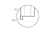
- the cylindrical member 81 has an inner diameter into which the terminal 11e can be inserted, and a protrusion 81a protruding from the tip is formed at a part of the tip of the cylindrical member 81 in the circumferential direction.
- the protrusion 81 a is formed so as to sandwich the wire 22 along the terminal 11 e with the terminal 11 e in a state where the terminal 11 e is inserted into the cylindrical member 81.
- the outer periphery of the protrusion 81 a is formed so as to be continuous with the outer periphery of the cylindrical member 81. That is, in order to sandwich the wire 22 between the terminal 11e, the protrusion 81a is formed at a position away from the inner diameter of the tubular member 81. Therefore, when the cylindrical member 81 rotates around the terminal 11e, the protrusion 81a circulates around the terminal 11e together with the cylindrical member 81, and the wire 22 sandwiched with the terminal 11e circulates around the terminal 11e. At this time, since the cross section of the protrusion 81a is formed in a circular shape, it is possible to prevent damage to the wire 22 that comes into contact with and slides around the protrusion 81a.
- one flange portion 11 a of the member to be wound 11 is gripped by the chuck 13.
- One flange portion 11 a of the member to be wound 11 is accommodated in a recess 14 d (see FIG. 4) at the tip of the chuck 13.
- the chuck opening / closing member 17 is moved to the tip side of the chuck 14 by the biasing force of the chuck spring 16 to narrow the interval between the divided pieces at the tip divided by the slit 14b.
- the one flange portion 11 a of the member to be wound 11 accommodated in the concave portion 14 d at the tip is gripped by the chuck 13.
- the wire rod 22 is fed out from the nozzle 51 extending horizontally in the X-axis direction and bent downward, and the end portion of the wire rod 22 fed out from the nozzle 51 is locked to the binding member 24 as the wire rod 22a at the beginning of winding.
- the locking of the wire 22 as the winding wire 22a to the binding member 24 is performed by moving the nozzle 51 by the nozzle moving mechanism 52 (see FIG. 1A). Specifically, as shown in FIG. 5, the nozzle 51 is moved, and the wire rod 22 a at the beginning of the winding bent downward from the tip of the nozzle 51 is inserted into the groove 24 a of the binding member 24. After that, as shown in FIG. 6, the nozzle 51 is made to circulate around the binding member 24 and then moved so as to be folded at the terminal 11 e of the member to be wound 11. In this way, the end of the wire 22 fed from the nozzle 51 is locked to the binding member 24, and the wire 22 fed from the nozzle 51 is locked to the terminal 11e.
- the binding member 24 and the chuck 13 are synchronously rotated in the same direction by the servo motor 27 (see FIG. 2).
- the coil 30 is obtained by winding the wire 22 fed from the nozzle 51 around the winding body 11c of the member 11 to be wound that rotates together with the chuck 13 as indicated by the solid arrow in FIG.
- the nozzle 51 is reciprocated within the range of the width of the winding drum portion 11c.
- the nozzle 51 is moved by an amount equal to the wire diameter of the wire 22 so that the wire 22 fed from the nozzle 51 is in close contact with the winding body 11c. Can be aligned and wound.
- the so-called aligned winding of the wire 22 can be performed.
- the rotation of the member to be wound 11 is stopped in a state where the terminal 11 e for winding the wire 22 b at the end of winding is directed to the nozzle 51.
- the nozzle 51 is moved by the nozzle moving mechanism 52 so as to be folded back at the terminal 11 e of the member to be wound 11, and is put on standby above the member to be wound 11.
- the wire 22 fed from the nozzle 51 after winding is locked to the terminal 11e for winding end.
- the nipper clamp device 71 is moved by the cutter moving mechanism 72 (see FIG. 2) so that the cutter teeth 71a and 71a sandwich the wire 22 in the vicinity of the terminal 11e.
- the wire rod 22 tries to return to the tension device 53 side by the tension device 53 (see FIG. 1A), but the wire rod 22 fed out from the horizontal nozzle 51 is bent downward, so that the wire rod 22 is connected to the nozzle 51.
- the return to the hole edge is prevented.
- the next winding can be prepared by bending the wire 22 downward.
- the wire rod 22b which is wound around the winding body 11c and drawn out and formed by cutting the nipper clamp device 71, is wound around the terminal 11e.
- This binding is performed by the wire binding means 80.
- the servo motor 27 slightly rotates the spindle 12 so that the terminal 11e faces upward and faces the cylindrical member 81 as shown in FIG.
- the terminal 11e and the cylindrical member 81 are relatively moved so that the terminal 11e is inserted into the cylindrical member 81. That is, in this embodiment, the motor moving mechanism 83 is entangled to move the servo motor 82, and the cylindrical member 81 provided coaxially with the rotating shaft 82a is lowered.
- the terminal 11e is inserted into the tubular member 81, and as shown in FIG. 10, the protrusion 81a is brought into contact with the outside of the wire 22 locked to the terminal 11e.
- the tubular member 81 is rotated around the terminal 11 e by the binding servo motor 82.
- the protrusion 81a that contacts the outside of the wire 22 locked to the terminal 11e circulates around the terminal 11e together with the tubular member 81, and the winding-finished wire 22b wound around the terminal 11e is placed around the terminal 11e. Tangle it.
- the tubular member 81 is raised by the outer diameter of the wire rod 22, and the winding end wire rod 22b is pivoted around the terminal 11e. It is preferable to wind spirally along the direction. In this way, the wire 22b at the end of winding is wound around the terminal 11e.
- the motor moving mechanism 83 moves together and raises the cylindrical member 81 together with the servo motor 82, so that the terminal 11e and the cylindrical member 81 move relative to each other. Then, the terminal 11 e is extracted from the cylindrical member 81.
- the winding wire 22 entangled with the tying member 24 is tied to the terminal 11e.
- the spindle 12 is slightly rotated in the reverse direction by the servo motor 27, and the terminal 11e is directed to the nozzle 51 side.
- the nipper clamp device 71 is moved by the cutter moving mechanism 72 so that the cutter teeth 71a sandwich the wire 22 in the vicinity of the terminal 11e.
- the cutter teeth 71a and 71a are closed in the vicinity of the terminal 11e by the nipper clamp device 71, and the wire 22 having a length that can be entangled with the terminal 11e is left in the vicinity of the terminal 11e, and the binding member 24 is connected to the terminal 11e.
- the cutter moving mechanism 72 takes out the wire 22 from the binding member 24 in a state where the nipper clamp device 71 holds the wire 22 remaining on the binding member 24. Then, the cutter moving mechanism 72 accommodates the wire rod 22 that has been moved to the wire rod storage box and taken out.
- the spindle 12 is slightly rotated again, and the terminal 11e around which the wire material 22a at the beginning of winding is wound is directed upward to face the cylindrical member 81.
- the motor moving mechanism 83 moves the tangled servo motor 82 to lower the cylindrical member 81 provided coaxially with the rotating shaft 82a.
- the cylindrical member 81 is rotated around the terminal 11e, and is brought into contact with the protrusion 81a on the outer side of the wire rod 22 locked to the terminal 11e.
- the protrusion 81a is rotated around the terminal 11e, and the end portion of the wire 22 wound around the terminal 11e is entangled around the terminal 11e.
- the tubular member 81 is raised by the outer diameter of the wire 22, and the wire 22a at the beginning of winding is pivoted around the terminal 11e. It is preferable to wind spirally along the direction. In this way, the wire 22a at the beginning of winding is entangled with the terminal 11e.
- the terminal 11e is extracted from the cylindrical member 81 by raising the cylindrical member 81 together with the binding servo motor 82 by the motor moving mechanism 83.
- the winding start wire 22a and the winding end wire 22b entangled with the terminal 11e in this way are electrically connected to the tangled terminal 11e.
- This connection can be performed by a conventionally known general method, for example, by soldering using a flux (JP2009-142839A).
- the coil 30 comprising the member to be wound 11 and the wire 22 wound around the member to be wound 11 a predetermined number of times. And a chip coil provided with these can be obtained.
- the cylindrical member 81 can prevent the terminal 11e from being inclined. .
- the wound member 11 and the terminal 11e themselves are prevented from being damaged due to the inclination of the terminal 11e.
- the end of the wire rod 22 that contacts the protrusion 81a protruding from the tip of the tubular member 81 is rotated around the terminal 11e by rotating the tubular member 81, and therefore the wire rod 22 around the terminal 11e where the inclination is prohibited. Can be wound.
- the wire 22 can be reliably wound around the terminal 11e, without damaging the to-be-wound member 11 or the terminal 11e itself.
- the protrusion 81a is formed at a position away from the inner diameter of the cylindrical member 81, the gap between the inner diameter of the cylindrical member 81 and the outer diameter of the terminal 11e can be further reduced, so that the terminal 11e is inclined. It can be prevented more effectively.
- the wire material at the beginning of winding is already wound around the terminal.
- the guided wire rod may get on the wire rod already entangled with the terminal, and the outer diameter of the tangled wire rod may be expanded.
- the tubular member 81 is raised while rotating together with the protrusion 81a, whereby the winding wire 22a is wound around the terminal 11e from the wound member 11 side. It can be wound spirally.
- the wire 22 does not further ride on the wire 22 entangled with the terminal 11e, and the wire 22 overlaps with the radial direction of the terminal 11e, and is entangled with the terminal 11e. It is possible to prevent the winding diameter of the bent wire 22 from being increased.
- the pin-shaped terminal 11e having a circular cross section has been described.
- the terminal 11e is not limited to the pin-shaped terminal having a circular cross section, but a rod-shaped or plate-shaped cross section. It may be.
- the projection 81a is described as the cylindrical member 81 formed at a position away from the inner diameter.
- the projection 81a projects to the inner diameter of the cylindrical member 81 as shown in FIGS.
- the outer periphery of 81a may be continuous.
- the terminal 11e shown in FIGS. 16 and 17 is a plate having a square cross section, and a plurality of cutouts 11f into which the wire 22 entangled there falls are formed on both sides thereof. Even in such a case, the cylindrical member 81 has an inner diameter into which the terminal 11e can be inserted.
- the protrusion 81a is formed so as to sandwich the wire 22 along the terminal 11e together with the terminal 11e in a state where the terminal 11e is inserted into the cylindrical member 81.
- the protrusion 81a When the notches 11f into which the wire 22 to be tangled is formed on both sides of the terminal 11e, as shown in FIG. 16, the protrusion 81a has an outer periphery continuous with the inner diameter of the cylindrical member 81. However, the protrusion 81a can sandwich the wire 22 together with the terminal 11e. For this reason, even in such a case, as shown in FIG. 17, when the cylindrical member 81 rotates around the terminal 11e, the protrusion 81a goes around the terminal 11e around the terminal 11e, and the terminal 11e. Further, the wire 22 sandwiched therewith is circulated around the terminal 11e. In this way, for example, the winding end wire 22b can be tied to the terminal 11e.
Landscapes
- Engineering & Computer Science (AREA)
- Power Engineering (AREA)
- Manufacturing & Machinery (AREA)
- Coil Winding Methods And Apparatuses (AREA)
- Manufacture Of Motors, Generators (AREA)
Abstract
L'invention concerne un dispositif d'enroulement qui comprend : un mécanisme de coupe de matériau de fil qui coupe un matériau de fil enroulé sur un organe d'enroulement près d'une borne du matériau de fil; et un mécanisme de liaison de matériau de fil qui enroule autour d'une borne une partie d'extrémité du matériau de fil qui est enroulé autour de l'organe d'enroulement et coupé par le mécanisme de coupe de matériau de fil. Le mécanisme de liaison de matériau de fil comprend en outre un organe cylindrique au travers duquel la borne peut être enfilée, et un moyen de rotation pour faire tourner l'organe cylindrique sur la borne. Une saillie est formée sur une partie d'une extrémité avant de l'organe cylindrique dans la direction de la circonférence qui fait saillie depuis l'extrémité avant. L'invention concerne également un procédé de liaison de la partie d'extrémité du matériau de fil à la borne qui aligne la partie d'extrémité du matériau de fil avec la borne, enfile la borne dans l'organe cylindrique sur quoi la saillie qui est formée sur la partie de l'extrémité avant dans la direction de la circonférence et qui fait saillie depuis l'extrémité avant, fait tourner le matériau cylindrique sur la borne, et enroule autour de la borne la partie d'extrémité du matériau de fil qui effectue le contact avec la saillie.
Priority Applications (3)
| Application Number | Priority Date | Filing Date | Title |
|---|---|---|---|
| CN201380041872.6A CN104520949B (zh) | 2012-08-08 | 2013-07-16 | 绕线装置以及向端子捆绕线材的方法 |
| US14/403,469 US9607761B2 (en) | 2012-08-08 | 2013-07-16 | Winding device and method for binding wire material to terminal |
| EP13827479.0A EP2884507B1 (fr) | 2012-08-08 | 2013-07-16 | Dispositif d'enroulement et procédé de liaison d'un matériau de filaire à une borne |
Applications Claiming Priority (2)
| Application Number | Priority Date | Filing Date | Title |
|---|---|---|---|
| JP2012175542A JP5936268B2 (ja) | 2012-08-08 | 2012-08-08 | 巻線装置及び線材の端子への絡げ方法 |
| JP2012-175542 | 2012-08-08 |
Publications (1)
| Publication Number | Publication Date |
|---|---|
| WO2014024646A1 true WO2014024646A1 (fr) | 2014-02-13 |
Family
ID=50067882
Family Applications (1)
| Application Number | Title | Priority Date | Filing Date |
|---|---|---|---|
| PCT/JP2013/069279 WO2014024646A1 (fr) | 2012-08-08 | 2013-07-16 | Dispositif d'enroulement et procédé de liaison d'un matériau de fil à une borne |
Country Status (6)
| Country | Link |
|---|---|
| US (1) | US9607761B2 (fr) |
| EP (1) | EP2884507B1 (fr) |
| JP (1) | JP5936268B2 (fr) |
| CN (1) | CN104520949B (fr) |
| TW (1) | TWI598282B (fr) |
| WO (1) | WO2014024646A1 (fr) |
Families Citing this family (17)
| Publication number | Priority date | Publication date | Assignee | Title |
|---|---|---|---|---|
| JP6336838B2 (ja) * | 2014-07-10 | 2018-06-06 | 日特エンジニアリング株式会社 | アンテナコイル形成用巻線装置及びそれを用いたアンテナコイル形成方法 |
| TWI581683B (zh) * | 2014-07-25 | 2017-05-01 | 友源機械有限公司 | 線頭捲收方法及線頭捲收器 |
| CN105225829B (zh) * | 2015-11-16 | 2017-01-25 | 资兴市弘电电子科技有限公司 | 一种双外引线端子线圈绕线机及绕线工艺 |
| TWI624225B (zh) * | 2016-10-06 | 2018-05-21 | 國立勤益科技大學 | 自動魚鉤綁線機 |
| TWM550926U (zh) * | 2017-04-25 | 2017-10-21 | 蔚然(南京)動力科技有限公司 | 用於將一電機定子的一線束組端接於一端子組的端接機台 |
| CN107465064B (zh) * | 2017-08-18 | 2024-03-22 | 厦门海普锐科技股份有限公司 | 端子穿线装置 |
| JP6268561B1 (ja) * | 2017-10-30 | 2018-01-31 | グッドファーマー技研株式会社 | 巻線端末絡げ装置 |
| CN110392973B (zh) * | 2018-02-23 | 2021-01-01 | E-Tec 株式会社 | 绕线装置 |
| BE1026729B1 (de) * | 2018-10-26 | 2020-05-28 | Phoenix Contact Gmbh & Co | Wickelvorrichtung zum Wickeln von Spulendraht für ein Relais |
| CN109742630B (zh) * | 2019-01-17 | 2020-09-01 | 襄阳司方德电子有限公司 | 一种应用于线束加工的自动化装置 |
| CN110148519B (zh) * | 2019-06-03 | 2021-12-10 | 四川省正元包装印务有限责任公司 | 一种网络滤波器引线手工绕线方法 |
| CN110335749B (zh) * | 2019-07-27 | 2021-06-15 | 东莞市慧研自动化设备科技有限公司 | 一种sq共模电感自动绕线缠脚设备及方法 |
| CN111048303B (zh) * | 2019-12-26 | 2021-05-25 | 昱博股份有限公司 | 微型扁平漆包线线圈的绕线方法 |
| CN111029131B (zh) * | 2019-12-26 | 2021-05-25 | 昱博股份有限公司 | 微型扁平漆包线线圈的绕线机 |
| CN111223661B (zh) * | 2020-03-18 | 2021-06-04 | 抚州市双菱磁性材料有限公司 | 一种高频变压器线圈的绕制设备 |
| CN111653427B (zh) * | 2020-07-20 | 2021-11-23 | 中国电子科技集团公司第二十四研究所 | 一种漆包扁线同轴绕制方法 |
| CN113928923B (zh) * | 2021-10-14 | 2023-09-26 | 国网江苏省电力有限公司苏州供电分公司 | 一种电箱的绕线装置及其操作方法 |
Citations (10)
| Publication number | Priority date | Publication date | Assignee | Title |
|---|---|---|---|---|
| US3244202A (en) * | 1963-12-05 | 1966-04-05 | Ibm | Wire wrapping devices |
| US3250302A (en) * | 1963-10-21 | 1966-05-10 | Zoltai John | Wire wrapping tool |
| JPS4812353B1 (fr) * | 1968-09-17 | 1973-04-19 | ||
| JPS5591812A (en) * | 1978-12-29 | 1980-07-11 | Siemens Ag | Winding and cutting device |
| JPH05299283A (ja) * | 1992-04-20 | 1993-11-12 | Tdk Corp | 巻線機 |
| JPH05315179A (ja) * | 1992-05-11 | 1993-11-26 | Matsushita Electric Ind Co Ltd | 巻線装置 |
| JPH07283065A (ja) | 1994-04-05 | 1995-10-27 | Nittoku Eng Co Ltd | コイル巻線機 |
| JP2009142839A (ja) | 2007-12-12 | 2009-07-02 | Mishima Kosan Co Ltd | 連続鋳造用鋳型 |
| JP2011217824A (ja) | 2010-04-06 | 2011-11-04 | Nittoku Eng Co Ltd | 開閉動作装置及び対象物の切断方法 |
| JP2012080037A (ja) * | 2010-10-06 | 2012-04-19 | Nittoku Eng Co Ltd | コイル巻線装置及びコイル巻線方法 |
Family Cites Families (13)
| Publication number | Priority date | Publication date | Assignee | Title |
|---|---|---|---|---|
| US3213894A (en) * | 1962-10-15 | 1965-10-26 | Western Electric Co | Methods of and apparatus for connecting a strand and an elongated member and methods of manufacturing such apparatus |
| AU461084B2 (en) | 1968-06-03 | 1975-04-24 | JOYCE MANN and LANCE LAWRENCE MANN | Improved mammary prosthesis |
| FR2098598A5 (fr) * | 1970-07-21 | 1972-03-10 | Cit Alcatel | |
| US4000764A (en) * | 1975-03-27 | 1977-01-04 | The Globe Tool And Engineering Company | Stator lead termination apparatus |
| US4111242A (en) * | 1977-05-24 | 1978-09-05 | Jacobson Ronald H | Wire wrapping and cut-off tool |
| JPS57107017A (en) * | 1980-12-25 | 1982-07-03 | Toko Inc | Lead wire winding method for electronic component |
| JPH071746B2 (ja) * | 1988-07-07 | 1995-01-11 | 松下電器産業株式会社 | コイル製造装置 |
| JP2747167B2 (ja) | 1992-05-15 | 1998-05-06 | 日特エンジニアリング株式会社 | 自動巻線機 |
| JP3068538B2 (ja) * | 1997-11-28 | 2000-07-24 | 日特エンジニアリング株式会社 | 巻線機 |
| CN100385580C (zh) * | 2002-08-28 | 2008-04-30 | 田中精机株式会社 | 绕线装置 |
| DE102005038440B3 (de) * | 2005-08-12 | 2007-01-25 | Tyco Electronics Amp Gmbh | Elektrischer Verbindungspin mit Drahtwicklung und Wicklungsumkehr sowie Verfahren zu dessen Herstellung |
| JP2007157956A (ja) * | 2005-12-05 | 2007-06-21 | Tamura Seisakusho Co Ltd | スイッチングトランス |
| JP4737621B2 (ja) * | 2006-01-30 | 2011-08-03 | Fdk株式会社 | 巻線部品 |
-
2012
- 2012-08-08 JP JP2012175542A patent/JP5936268B2/ja active Active
-
2013
- 2013-07-16 EP EP13827479.0A patent/EP2884507B1/fr active Active
- 2013-07-16 CN CN201380041872.6A patent/CN104520949B/zh active Active
- 2013-07-16 WO PCT/JP2013/069279 patent/WO2014024646A1/fr active Application Filing
- 2013-07-16 US US14/403,469 patent/US9607761B2/en active Active
- 2013-07-19 TW TW102125897A patent/TWI598282B/zh active
Patent Citations (10)
| Publication number | Priority date | Publication date | Assignee | Title |
|---|---|---|---|---|
| US3250302A (en) * | 1963-10-21 | 1966-05-10 | Zoltai John | Wire wrapping tool |
| US3244202A (en) * | 1963-12-05 | 1966-04-05 | Ibm | Wire wrapping devices |
| JPS4812353B1 (fr) * | 1968-09-17 | 1973-04-19 | ||
| JPS5591812A (en) * | 1978-12-29 | 1980-07-11 | Siemens Ag | Winding and cutting device |
| JPH05299283A (ja) * | 1992-04-20 | 1993-11-12 | Tdk Corp | 巻線機 |
| JPH05315179A (ja) * | 1992-05-11 | 1993-11-26 | Matsushita Electric Ind Co Ltd | 巻線装置 |
| JPH07283065A (ja) | 1994-04-05 | 1995-10-27 | Nittoku Eng Co Ltd | コイル巻線機 |
| JP2009142839A (ja) | 2007-12-12 | 2009-07-02 | Mishima Kosan Co Ltd | 連続鋳造用鋳型 |
| JP2011217824A (ja) | 2010-04-06 | 2011-11-04 | Nittoku Eng Co Ltd | 開閉動作装置及び対象物の切断方法 |
| JP2012080037A (ja) * | 2010-10-06 | 2012-04-19 | Nittoku Eng Co Ltd | コイル巻線装置及びコイル巻線方法 |
Also Published As
| Publication number | Publication date |
|---|---|
| TW201406642A (zh) | 2014-02-16 |
| EP2884507A1 (fr) | 2015-06-17 |
| JP5936268B2 (ja) | 2016-06-22 |
| US20150115092A1 (en) | 2015-04-30 |
| JP2014036067A (ja) | 2014-02-24 |
| CN104520949A (zh) | 2015-04-15 |
| CN104520949B (zh) | 2017-02-22 |
| EP2884507A4 (fr) | 2016-04-27 |
| EP2884507B1 (fr) | 2018-12-19 |
| US9607761B2 (en) | 2017-03-28 |
| TWI598282B (zh) | 2017-09-11 |
Similar Documents
| Publication | Publication Date | Title |
|---|---|---|
| WO2014024646A1 (fr) | Dispositif d'enroulement et procédé de liaison d'un matériau de fil à une borne | |
| KR101665281B1 (ko) | 코일 제조 장치 | |
| JP6315792B2 (ja) | コイル製造装置 | |
| US20160351329A1 (en) | Winding device and winding method | |
| JP6578227B2 (ja) | 巻線装置及び線材の端子への絡げ方法 | |
| JP2009055711A (ja) | スピンドル巻線装置 | |
| JP6436569B2 (ja) | コイル製造装置 | |
| US9729031B2 (en) | Winding apparatus and winding method | |
| JP2008211899A (ja) | 多極電機子の巻線装置及び巻線方法 | |
| JP2018093125A (ja) | 巻線装置及び巻線方法 | |
| WO2014045808A1 (fr) | Dispositif d'enroulement et procédé d'enroulement | |
| JP2015050364A (ja) | コイルの製造装置及びコイルの製造方法 | |
| JP6232238B2 (ja) | 巻線装置および巻線方法 | |
| EP1376829A3 (fr) | Bobinage stratifiée par mouvement perfectionné de l'aiguille | |
| US2765124A (en) | Coil winding apparatus | |
| JP6803636B2 (ja) | 線材絡げ装置並びにそれを用いた巻線装置及び線材の絡げ方法 | |
| JP5991275B2 (ja) | 巻線部品の結線方法および結線装置 | |
| JP3963899B2 (ja) | 巻線装置 | |
| JP2014093428A (ja) | 巻線装置及び巻線方法 | |
| JP5516067B2 (ja) | コイル部品の製造装置 |
Legal Events
| Date | Code | Title | Description |
|---|---|---|---|
| 121 | Ep: the epo has been informed by wipo that ep was designated in this application |
Ref document number: 13827479 Country of ref document: EP Kind code of ref document: A1 |
|
| WWE | Wipo information: entry into national phase |
Ref document number: 2013827479 Country of ref document: EP |
|
| WWE | Wipo information: entry into national phase |
Ref document number: 14403469 Country of ref document: US |
|
| NENP | Non-entry into the national phase |
Ref country code: DE |