WO2014017576A1 - 多刃エンドミル - Google Patents
多刃エンドミル Download PDFInfo
- Publication number
- WO2014017576A1 WO2014017576A1 PCT/JP2013/070147 JP2013070147W WO2014017576A1 WO 2014017576 A1 WO2014017576 A1 WO 2014017576A1 JP 2013070147 W JP2013070147 W JP 2013070147W WO 2014017576 A1 WO2014017576 A1 WO 2014017576A1
- Authority
- WO
- WIPO (PCT)
- Prior art keywords
- blade
- rake face
- outer peripheral
- end mill
- groove
- Prior art date
Links
Images


Classifications
-
- B—PERFORMING OPERATIONS; TRANSPORTING
- B23—MACHINE TOOLS; METAL-WORKING NOT OTHERWISE PROVIDED FOR
- B23C—MILLING
- B23C5/00—Milling-cutters
- B23C5/02—Milling-cutters characterised by the shape of the cutter
- B23C5/10—Shank-type cutters, i.e. with an integral shaft
-
- B—PERFORMING OPERATIONS; TRANSPORTING
- B23—MACHINE TOOLS; METAL-WORKING NOT OTHERWISE PROVIDED FOR
- B23C—MILLING
- B23C2210/00—Details of milling cutters
- B23C2210/08—Side or top views of the cutting edge
- B23C2210/082—Details of the corner region between axial and radial cutting edges
-
- B—PERFORMING OPERATIONS; TRANSPORTING
- B23—MACHINE TOOLS; METAL-WORKING NOT OTHERWISE PROVIDED FOR
- B23C—MILLING
- B23C2210/00—Details of milling cutters
- B23C2210/20—Number of cutting edges
- B23C2210/209—Number of cutting edges twelve
-
- B—PERFORMING OPERATIONS; TRANSPORTING
- B23—MACHINE TOOLS; METAL-WORKING NOT OTHERWISE PROVIDED FOR
- B23C—MILLING
- B23C2210/00—Details of milling cutters
- B23C2210/32—Details of teeth
- B23C2210/321—Lands, i.e. the area on the rake face in the immediate vicinity of the cutting edge
-
- B—PERFORMING OPERATIONS; TRANSPORTING
- B23—MACHINE TOOLS; METAL-WORKING NOT OTHERWISE PROVIDED FOR
- B23C—MILLING
- B23C2210/00—Details of milling cutters
- B23C2210/40—Flutes, i.e. chip conveying grooves
-
- B—PERFORMING OPERATIONS; TRANSPORTING
- B23—MACHINE TOOLS; METAL-WORKING NOT OTHERWISE PROVIDED FOR
- B23C—MILLING
- B23C2210/00—Details of milling cutters
- B23C2210/44—Margins, i.e. the part of the peripheral suface immediately adacent the cutting edge
-
- B—PERFORMING OPERATIONS; TRANSPORTING
- B23—MACHINE TOOLS; METAL-WORKING NOT OTHERWISE PROVIDED FOR
- B23C—MILLING
- B23C2210/00—Details of milling cutters
- B23C2210/48—Chip breakers
-
- B—PERFORMING OPERATIONS; TRANSPORTING
- B23—MACHINE TOOLS; METAL-WORKING NOT OTHERWISE PROVIDED FOR
- B23C—MILLING
- B23C2210/00—Details of milling cutters
- B23C2210/54—Configuration of the cutting part
-
- B—PERFORMING OPERATIONS; TRANSPORTING
- B23—MACHINE TOOLS; METAL-WORKING NOT OTHERWISE PROVIDED FOR
- B23C—MILLING
- B23C2215/00—Details of workpieces
- B23C2215/44—Turbine blades
-
- B—PERFORMING OPERATIONS; TRANSPORTING
- B23—MACHINE TOOLS; METAL-WORKING NOT OTHERWISE PROVIDED FOR
- B23C—MILLING
- B23C2250/00—Compensating adverse effects during milling
- B23C2250/12—Cooling and lubrication
-
- Y—GENERAL TAGGING OF NEW TECHNOLOGICAL DEVELOPMENTS; GENERAL TAGGING OF CROSS-SECTIONAL TECHNOLOGIES SPANNING OVER SEVERAL SECTIONS OF THE IPC; TECHNICAL SUBJECTS COVERED BY FORMER USPC CROSS-REFERENCE ART COLLECTIONS [XRACs] AND DIGESTS
- Y10—TECHNICAL SUBJECTS COVERED BY FORMER USPC
- Y10T—TECHNICAL SUBJECTS COVERED BY FORMER US CLASSIFICATION
- Y10T407/00—Cutters, for shaping
- Y10T407/19—Rotary cutting tool
- Y10T407/1946—Face or end mill
- Y10T407/1948—Face or end mill with cutting edge entirely across end of tool [e.g., router bit, end mill, etc.]
Definitions
- the present invention is mounted on a machine tool when a thin-walled impeller, a blade, or the like used in a rotary machine device such as a turbine or a supercharger is manufactured by cutting using a 3-axis or 5-axis control machine tool.
- the present invention relates to an improved multi-blade end mill that can perform high-feed cutting on a member such as an impeller.
- Thin-walled impellers (impellers) and blades used in rotating machinery such as turbines and turbochargers are made of Ni-base heat-resistant alloys, stainless steel, or titanium alloys, which are difficult-to-cut alloy members (materials). It is manufactured through a cutting process in which a multi-axis control is performed while rotating a cutting tool such as an end mill, and the alloy member is subjected to roughing, intermediate finishing and finishing.
- the surface of the alloy member must be finished into a curved surface in the finishing process, so it has traditionally consisted of a ball end mill, a tapered ball end mill, or an outer peripheral edge, a corner edge, and a bottom edge.
- a radius end mill with a cutting edge is used.
- a solid-type radius end mill (hereinafter also referred to as “multi-blade end mill”) having a large number of cutting edges, for example, six or more cutting edges, at the tip end of the tool body is gradually being used.
- FIG. 11 specifically shows the example described in FIG.
- the blade groove 8 is formed on the rear side in the rotational direction R on the radially outer peripheral side of the gash 7 formed on the front side in the rotational direction R of the bottom blade 6. It is considered that the formation of the blade groove 8 continuously to the gash 7 makes it difficult for the chips to stay in the gash 7 and enhances the discharge of the chips cut by the bottom blade 6.
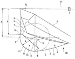
- FIG. 12 shows an example of an end mill in which a blade groove is formed near the outer periphery in the radial direction of the gasche formed near the center in the radial direction other than Patent Document 1 (see Patent Document 2).
- FIG. 12 shows FIG. 2 of Patent Document 2.
- a chip discharge groove 4 corresponding to the blade groove of Patent Document 1 is formed continuously toward the outer periphery in the radial direction of the gash 7, and the rake face 11 of the corner blade 12 is provided between the chip discharge groove 4 and the gash 7. Since the recess 10 is formed (paragraphs 0017 and 0018), the gasche 7 and the chip discharge groove 4 communicate with each other through the recess 10.
- a corner blade 12 that draws an arc is formed from the point Q to the rear end portion side of the end mill on the radial center side beyond the tip P of the arc, up to the start point Q of the bottom blade 9;
- the intersecting line L that defines the recess 10 on the radial center side with respect to the straight line passing through the center axis passing through the tip P, the chips generated by the corner blade 12 do not wrap around the bottom blade rake face 8 side.
- the corner blade rake face 11 can be discharged (paragraphs 0019 to 0024).
- Patent Document 1 since the inclination of the bottom surface of the gash 7 from the radial center (rotary axis) side to the outer peripheral side is gentle and parallel to the end face of the end mill, The chip discharge effect cannot be expected. Further, since the blade groove 8 continuing to the gash 7 is formed to be biased toward the outer periphery in the radial direction, it is considered that the induction effect from the gash 7 to the blade groove 8 cannot be expected.
- the rake face 4a of the outer peripheral blade 4 also serves as the rake face of the corner R blade 5, and therefore the blade groove 8 (chip pocket) as shown by the solid line in FIG. ) Can be taken somewhat larger.
- the blade groove 8 is formed biased toward the outer periphery in the radial direction, the advantage of increasing the volume of the blade groove 8 is not utilized.
- the chip pocket (CP) is the sum of the volume of the gasche and the volume of the blade groove, and it can be said that the larger the volume, the higher the chip storage capacity and the discharge effect.
- the solid line shows a cross section when the rake face 4a of the outer peripheral blade 4 also serves as the rake face of the corner R blade 5, and the two-dot chain line shows the rake face 4a of the outer peripheral blade 4 of the corner R blade 5.
- the cross section when not serving as a rake face is shown.
- Patent Document 2 in order to prevent the chips generated by the corner blade 12 from wrapping around the gash 7 side, a wall surface raised on the gash 7 side surface of the recess 10 interposed between the gash 7 and the chip discharge groove 4 13 is formed (paragraph 0019). For this reason, the bottom blade 9 is generated, and the recess 10 may inhibit the discharge effect of the chips that have fallen into the gash 7 to the chip discharge groove 4, and the chips from the gash 7 to the chip discharge groove 4 may be blocked. Inductive effects are not expected.
- the present invention proposes a multi-blade end mill having a configuration in which the chip discharging effect from the gasche and the guiding effect to the blade groove are remarkably enhanced as compared with the example of Patent Document 1.
- the basic object of the present invention is to improve the structure of the cutting edge portion, which has good chip dischargeability even when high-feed cutting is performed on a difficult-to-cut alloy member. It is to provide a radius end mill for blades.
- the present invention comprises a thin member of a difficult-to-cut alloy that has been difficult in the past while using a multi-blade radius end mill (multi-blade end mill) mounted on a 3-axis or 5-axis NC machine tool.
- the surface of a hard-to-machine alloy member such as an impeller with a curved surface can be cut with high efficiency (high speed machining) for a long time with a single multi-blade end mill for high feed finishing.
- the purpose is to.
- an object is to improve the discharge of generated chips even when high-feed cutting is performed.
- the “multi-blade” is applied from the rotary shaft O side (radial center side) of the tip of the tool body (multi-blade end mill) to the radially outer peripheral side of the shank portion 2a.
- the multi-blade end mill of the invention described in claim 1 is formed at the tip of the shank portion, and has a bottom blade and a corner R blade continuous with the bottom blade from the rotary shaft O side to the radially outer peripheral side of the shank portion. And the radial direction between the cutting edge part provided with a plurality of cutting edges composed of an outer peripheral edge continuous with the corner R edge, and the cutting edge adjacent to the rotation direction R around the rotation axis O.
- a multi-blade end mill having a gash and a groove formed on the center side and the outer peripheral side, respectively,
- the rake face of the cutting edge is adjacent to the rake face of the bottom edge from the radial center side to the outer peripheral side, and forms a surface different from the rake face of the bottom edge, It is composed of the rake face of the outer peripheral blade that also serves as the rake face of the corner R blade,
- the flank face of the cutting edge extends from the radially center side to the outer peripheral side, the flank face of the bottom blade, the flank face of the corner R blade adjacent to the flank face of the bottom blade, and the relief of the corner R blade.
- the flank of the outer peripheral blade adjacent to the surface The blade groove is composed of a rake face of the outer peripheral blade, a blade groove surface facing the front side in the rotation direction R, and a bottom surface formed at a boundary between the rake face of the outer peripheral blade and the blade groove surface.
- the intersection of the convex ridge line located at the boundary between the rake face of the bottom edge and the rake face of the outer peripheral edge, and the convex ridge line located at the boundary between the rake face of the bottom edge and the bottom face of the blade groove It is characterized in that it enters the center in the radial direction from the boundary between the flank face of the corner R blade and the flank face of the bottom blade.
- the “radial direction” in claim 1 refers to a radial direction passing through the rotation axis O on the cross section perpendicular to the rotation axis O, and the gasche 7 is configured such that the cutting edge portion 2b is connected to the tip end side of the shank portion 2a, ie, a multi-blade end mill.
- 1 is formed between the flank surfaces 6b, 6b of the bottom blades 6, 6 adjacent to the rotation direction R, near the rotation axis O (center) in the radial direction when viewed from the tip 1a side to the shank portion 2a side.
- the blade groove 8 is formed between the flank surfaces 5b and 5b of the corner R blades 5 and 5 adjacent to the rotation direction R on the outer peripheral side in the radial direction.
- the “tip portion of the shank portion 2a” is synonymous with the “tip portion 1a of the multi-blade end mill 1”.
- the rake face 4a of the outer peripheral edge 4 forms a different surface from the rake face 6a of the lower edge 6
- the rake face 4a of the outer peripheral blade 4 also serves as the rake face of the corner R blade 5” means that the rake face 4a of the outer peripheral blade 4 extends from the outer peripheral blade 4 to the corner R blade 5.
- the rake face 4a of the blade 4 extends from the outer peripheral blade 4 to the bottom blade 6 as described later.
- the blade groove 8 is constituted by a rake surface 4a of the outer peripheral blade 4 and a blade groove surface 8a facing the front side in the rotational direction R of the multi-blade end mill 1, but the rake surface 4a of the outer peripheral blade 4 and the blade groove surface.
- a bottom surface 8b that forms the bottom of the blade groove 8 is formed at the boundary with 8a.
- the bottom surface 8b has a width in the rotation direction R (circumferential direction of the multi-blade end mill 1), and as shown in FIG. 5, between the bottom surface 8b and the rake face 4a of the outer peripheral blade 4 on both sides in the width direction (rotation direction R).
- a boundary line 10a is formed, and a boundary line 10b is formed between the bottom surface 8b and the blade groove surface 8a. Both the boundary line 10a and the boundary line 10b form a concave ridgeline.
- the bottom surface 8b may be formed in a downwardly convex curved surface, a V-shape, or the like, or in a flat surface.
- a convex ridge line 64 positioned at the boundary between the rake face 6a of the bottom edge 6 and the rake face 4a of the outer peripheral edge 4" refers to the corner R edge 5 and the bottom that are continuous in the radial direction as shown in FIGS.
- the convex ridgeline forming the blade 6 moves from the corner R blade 5 to the bottom blade 6, it indicates a ridgeline branched toward the gash surface 7 a side (the rake surface 6 a side of the bottom blade 6) facing the bottom blade 6. .
- the ridge line 64 branches from the vicinity of the boundary between the flank 5b of the corner R blade 5 and the flank 6b of the bottom blade 6 to the gash surface 7a, and the boundary line between the rake surface 6a of the bottom blade 6 and the rake surface 4a of the outer peripheral blade 4 become.
- the “convex ridge line 68 positioned at the boundary between the rake face 6a of the bottom blade 6 and the bottom surface 8b of the blade groove 8” is on the extended line of the boundary line 10b between the bottom surface 8b of the blade groove 8 and the blade groove surface 8a.
- the ridge line from the boundary line 10b toward the bottom blade 6 (the rake face 6a side of the bottom blade 6) facing the gash 7 is indicated.
- the ridge line 68 is a boundary line between the rake face 6 a of the bottom blade 6 and the bottom face 8 b of the blade groove 8.
- the ridge line 68 is directed from the position where the blade groove surface 8 a facing the rake face 4 a of the outer peripheral blade 4 to the front side in the rotation direction R and the bottom surface 7 b of the gash 7 toward the bottom blade 6, and intersects the ridge line 64.
- the bottom surface 7b of the gash 7 is formed at the boundary between the scoop surface 6a of the bottom blade 6 and the gash surface 7a facing the front side in the rotational direction R (Claim 2).
- the ridgeline 64 divides (separates) the rake face 4a of the outer peripheral edge 4 from the rake face 6a of the bottom edge 6, it is shown in FIGS. 5 and 6 by branching from the corner R edge 5 toward the gash face 7a. In this manner, the rake face 4a of the outer peripheral blade 4 is caused to enter (be cut into) the rake face 6a side of the bottom blade 6.
- the ridge line 68 partitions (separates) the bottom surface 8b of the blade groove 8 from the rake face 6a of the bottom blade 6, so that the bottom surface 8b of the blade groove 8 moves toward the bottom blade 6 side from the boundary line 10b. To the side of the rake face 6a.
- the rake face 4a of the outer peripheral blade 4 and the bottom surface 8b of the blade groove 8 constitute the blade groove 8. Therefore, both the rake face 4a of the outer peripheral blade 4 and the bottom surface 8b of the blade groove 8 enter the rake face 6a side of the bottom blade 6. Thus, an effect of inducing the fall of the chips existing in the gash 7 into the blade groove 8 is born, and the discharging property of the chips from the gash 7 is improved.
- a convex ridge line 64 located at the boundary between the rake face 6 a of the bottom edge 6 and the rake face 4 a of the outer peripheral edge 4, and a convex edge located at the boundary between the rake face 6 a of the bottom edge 6 and the bottom face 8 b of the blade groove 8.
- the intersection 66 of the ridge line 68 enters the radial rotation axis O side from the boundary between the flank 5 b of the corner R blade 5 and the flank 6 b of the bottom blade 6.
- flank 6b of the bottom blade 6 and the flank 5b of the corner R blade 5 which are adjacent to each other in the radial direction, and between the flank 5b of the corner R blade 5 and the flank 4b of the outer peripheral blade 4.
- this line may not be visible to the naked eye.
- the flank 6b of the adjacent bottom blade 6 and the flank 5b of the corner R blade 5, and the flank 5b of the corner R blade 5 and the flank 4b of the outer peripheral blade 4 are used as the flank 5b of the corner R blade 5.
- the boundary line is not visible. There may be a boundary line where the curvature changes.
- intersection 66 of the ridge line 64 and the ridge line 68 enters the rotary shaft O side in the radial direction of the shank portion 2a from the boundary between the flank 6b of the bottom blade 6 and the flank 5b of the corner R blade 5”.
- 64 and the ridgeline 68 are located on the rotation axis O side from the boundary between the flank 5b of the corner R blade 5 and the flank 6b of the bottom blade 6, and the ridgeline 64 and the ridgeline 68 are radially outer periphery. That is, the lines cross each other from the side toward the center side (rotation axis O).
- the rake face 4a of the outer peripheral blade 4 also serves as the rake face of the corner R blade 5, the advantage of increasing the volume of the blade groove 8 is utilized. It becomes possible to enlarge the volume, that is, the volume of the chip pocket (CP). Expansion of the volume of the blade groove 8 means that the chip storage capacity and the discharge effect are improved.
- the chip pocket (CP) is the sum of the volume of the space forming the gash 7 and the volume of the space forming the blade groove 8.
- the cutting groove 8 extends from the outer peripheral side in the radial direction to the center side (rotation axis O side) and extends from the corner R blade 5 to the bottom blade 6, so that the rake face 4 a of the outer peripheral blade 4 is formed on the corner R blade 5.
- the advantage of taking a large volume of the blade groove 8 (chip pocket) by serving as a rake face is utilized. Since the rake face 4a of the outer peripheral blade 4 also serves as the rake face of the corner R blade 5, the volume of the blade groove 8 can be increased, as described above, in the corner R blade 5 as shown in FIG. 7- (b).
- FIG. 7- (b) shows a cross section taken along the line zz of FIG.
- the rake face 4a of the outer peripheral blade 4 also serves as the rake face of the corner R blade 5 is not to form the rake face of the corner R blade 5, the rake of the cutting edge 3 including the rake face 4a of the outer peripheral blade 4 is included. It also has the meaning of reducing the labor of processing for forming (grinding) the entire surface and improving the workability of the entire rake face of the cutting edge 3.
- the rake face 5a of the corner R blade 5 When the rake face 5a of the corner R blade 5 is formed, as shown in FIG. 7- (b), it is indicated by a two-dot chain line hatching on the straight blade groove 8 side connecting the corner R blade 5 and the boundary line 10a. A protruding portion is formed.
- the rake face 4a of the outer peripheral blade 4 since the rake face 4a of the outer peripheral blade 4 also serves as the rake face of the corner R blade 5, no hatched protrusion is formed, so that only the protrusion when the rake face 5a is present is provided in the blade groove.
- the volume of 8 (chip pocket) is increased.
- the rake face 4a Since the rake face 4a is positioned on the rear side in the rotation direction R with respect to the rake face 6a, the chips existing in the gash 7 are likely to enter the blade groove 8 with the rotation of the multi-blade end mill 1, and the blade groove Since the chips in 8 are easily discharged out of the multi-blade end mill 1, chips are also discharged from the gash 7 and the blade groove 8 from this point (the rake face 4 a is located on the rear side in the rotation direction R of the rake face 6 a). It can be said that the improvement of property is achieved.
- the bottom surface 8b of the blade groove 8 has a width in the rotation direction R.
- any one of the cutting blade 3 such as the bottom blade 6 and the corner R blade 5 can be used. This has the effect of making it difficult for stagnation of chips that have fallen directly into the blade groove 8 from the gash 7 or from the gash 7.
- the bottom surface 7b of the gasche 7 is given a width in the rotational direction R in order to improve the dischargeability of the chips falling into the gasche 7.
- both the gash 7 and the bottom surfaces 7b, 8b of the blade groove 8 have a width, but if there is a stagnation of the chips in the blade groove 8, the discharge of the chips from the gash 7 may be hindered. .
- the blade groove is relatively It is appropriate that the width of the bottom surface 8b of 8 is secured larger than the width of the bottom surface 7b of the gash 7.
- the bottom surface 7b of the gash 7 and the bottom surface 8b of the blade groove 8 have a width.
- the width of the bottom surface 8b of the blade groove 8 is larger than the width of the bottom surface 7b of the gash 7. Since it is relatively small, when the stagnation of the chip occurs in the blade groove 8, the discharge of the chip from the gasche 7 may be hindered or the discharge may stagnate.
- the width of the bottom surface 8b of the blade groove 8 is larger than the width of the bottom surface 7b of the gash 7 (Claim 2), the stagnation of chips in the blade groove 8 hardly occurs. The possibility of hindering emissions and the possibility of stagnation are reduced.
- the flank 4b of the outer peripheral blade 4 is adjacent to the surface 2c of the shank portion 2a and forms a continuous surface with the surface 2c as shown in FIGS. 2 and 10, so that the intersection 66 of the ridgeline 64 and the ridgeline 68 is the flank. “Intrusion from the boundary between 6b and the flank 5b toward the center in the radial direction” means that the rake face 4a of the outer peripheral blade 4 extends from the flank 6b of the bottom blade 6 to the surface 2c of the shank portion 2a. In other words.
- the scooping surface 4a of the outer peripheral blade 4 extends from the flank 6b of the bottom blade 6 to the surface 2c of the shank portion 2a, so that chips from the gash 7 through the blade groove 8 are removed from the multi-blade end mill 1. It can be said that the discharge performance and the discharge speed of the fuel are improved.
- the boundary line 10a between the rake face 4a of the outer peripheral blade 4 and the boundary line 10b between the blade groove surface 8a are formed as concave ridge lines on both sides in the width direction of the bottom surface 8b of the blade groove 8.
- the boundary line 10a between the bottom face 8b and the rake face 4a of the outer peripheral edge 4 is a convex ridge line 64 at the boundary between the rake face 6a and the rake face 4a, and the rake face 6a and the bottom face 8b.
- the rake face 4a of the outer peripheral blade 4 and the bottom face 8b of the blade groove 8 form a valley, and therefore exist in the gash 7. It can be said that the chips to be dropped easily fall into the blade groove 8 and the effect of guiding from the gash 7 to the blade groove 8 is further improved.
- the volume of the space of the blade groove 8 constituted by the rake face 4a of the outer peripheral blade 4 and the blade groove surface 8a facing the front side in the rotation direction R is such that the blade groove surface 8a is in contact with the bottom surface 7b of the gash 7. Further increase by having at least two surfaces of an inner side surface 81a in contact with the rear side in the rotational direction R and a different surface from the inner side surface 81a and an outer side surface 82a in contact with the gash surface 7a in the radial direction (Claim 4). To do.
- the gash surface 7a is a surface that faces the rake surface 6a of the bottom blade 6 in the rotational direction R front side. In this case, as shown in FIG.
- the outer side surface 82a is inclined with respect to the inner side surface 81a from the shank portion 2a side to the tip end portion 1a side of the multi-blade end mill 1 in the rotational direction R from the rear side to the front side. From the direction center side to the outer peripheral side, the rotation direction R is inclined from the rear side to the front side, and a convex ridge line appears as a boundary line 88 between the inner side surface 81a and the outer side surface 82a. “Having at least two surfaces” means that the blade groove surface 8a may have three or more surfaces.
- the outer side surface 82a is inclined from the rear side in the rotational direction R toward the front side 1a from the shank part 2a side to the front end part 1a side of the multi-blade end mill 1” means that the multi-blade end mill 1 is viewed from the side face toward the radial center.
- the inclination of the outer surface 82a is described, and “inclination from the rear side to the front side in the rotational direction R from the center side in the radial direction to the front side” means that the multi-blade end mill 1 is moved from the tip 1a side.
- the inclination state of the outer side surface 82a when it sees to the shank part 2a side is described.
- the inner side surface 81a is in contact with the bottom surface 7b of the gash 7 on the rear side in the rotational direction R” means that the inner side surface 81a is located on the extension line of the convex ridge line 68 and the inner surface 81 It means that the side surface 81a is adjacent and the inner side surface 81a is positioned on the rear side in the rotational direction R relative to the bottom surface 7b. Since the boundary line between the bottom surface 7b and the inner surface 81a is a part of the convex ridge line 68 located at the boundary between the rake face 6a and the bottom surface 8b, the bottom surface 7b and the inner surface 81a are Adjacent to each other with the convex ridgeline 68 in between.
- the outer surface 82a is in contact with the gash surface 7a in the radial direction” means that the gash surface 7a and the outer surface 82a are adjacent to each other with a boundary line therebetween, and the outer surface 82a is relatively radially outer side of the gash surface 7a. Say that you are located in.
- the boundary line between the gash surface 7a and the outer surface 82a is a boundary line 78 between the gash surface 7a and the blade groove surface 8a.
- the boundary line 78 is between the inner surface 81a and the outer surface 82a. It continues to the convex ridgeline which is the boundary line 88.
- the outer surface 82a is inclined with respect to the inner surface 81a from the shank portion 2a side to the tip portion 1a side in the rotational direction R from the rear side to the front side” as shown in FIG. With respect to 81a, it inclines toward the flank 5b side of the corner R blade 5 located in the rotation direction R front side from the bottom surface 8b side of the blade groove 8 toward the front side from the rotation direction R.
- the outer surface 82a is inclined from the center in the radial direction toward the outer periphery with respect to the inner surface 81a in the rotational direction R from the rear side to the front side” means that the outer surface 82a is inclined toward the front side with respect to the inner surface 81a.
- the direction of rotation R is inclined from the rear side to the front side from the center side in the radial direction to the outer peripheral side.
- the outer surface 82a extends from the bottom surface 8b side of the blade groove 8 to the flank 5b side of the corner R blade 5 positioned on the front side in the rotation direction R, and the back surface of the cutting edge 3 (surface on the rear side in the rotation direction R).
- the side surface is formed so as to be thinly cut or scraped off.
- the outer side surface 82a is inclined with respect to the inner side surface 81a from the shank portion 2a side to the front end portion 1a side in the rotational direction R from the rear side to the front side, and at the same time from the radial center side to the outer peripheral side. There is also a case of tilting from the front side.
- the blade groove surface 8 a has at least two surfaces of an inner surface 81 a and an outer surface 82 a that forms a surface different from the inner surface 81 a, so that the position of the rake surface 4 a of the outer peripheral blade 4 on the tip portion 1 a side. And the distance in the circumferential direction (rotation direction R) between the blade groove surface 8a facing this and the position on the tip 1a side increases, the volume of the space in the blade groove 8 increases, and the volume of the gash 7 increases. The volume of the chip pocket (CP) combined with the above increases. The advantage that the chip discharging performance is further improved by increasing the volume of the space of the blade groove 8 (chip pocket) is obtained.
- the intersection of the convex ridge line at the boundary between the rake face of the bottom edge and the rake face of the outer peripheral edge and the ridge line of the boundary edge between the rake face of the bottom edge and the bottom face of the blade groove is the bottom flank face and the corner R edge.
- the rake face of the outer peripheral blade extends from the flank face of the bottom blade to the surface of the shank, which improves the discharge performance and discharge speed of chips from the gash through the blade groove to the outside of the multi-blade end mill.
- the intersection of the convex ridgeline at the boundary between the bottom edge rake face and the peripheral edge rake face and the ridgeline at the boundary edge between the bottom edge rake face and the bottom surface of the groove groove is the difference between the bottom edge flank face and the corner R edge flank face.
- FIG. 2 is an end view of a multi-blade end mill showing a state in which the cutting edge portion shown in FIG. 1 is viewed from the end face side in the rotation axis direction.
- FIG. 3 is a sectional view taken along line xx in FIG. 2. It is the perspective view which showed a mode that the cutting edge part of the multiblade end mill shown in FIG. 1 was seen from the front-end
- FIG. 6 is an arrow view taken along line yy in FIG. 5.
- FIG. 5A is a cross-sectional view taken along the line zz in FIG.
- FIG. 4 is a cross-sectional end view taken along the line -z, showing the present invention without the rake face of the corner R blade 5 with a solid line, and showing a reference example with a rake face of the corner R blade 5 with a chain line. It is the perspective view which showed the other manufacture example of the multiblade end mill of this invention in case a blade groove surface consists of two surfaces, an inner surface and an outer surface.
- FIG. 3 is a partially enlarged side view of the end mill described in Patent Document 2 (FIG. 2 of Patent Document 2).
- high speed machining when a Ni-base heat-resistant alloy member is used as a work material, “high speed machining (high speed machining)” generally refers to machining with a cutting speed Vc of 60 to 80 mm / min. If the cutting speed Vc is less than 60 mm / min, the machinability deteriorates and the cutting resistance becomes excessive. On the other hand, if the cutting speed Vc exceeds 80 mm / min, the cutting temperature becomes very high, and the wear of the cutting edge early and the phenomenon that chips are welded to the cutting edge occur.
- a more preferable range of the cutting speed Vc is 65 to 80 mm / min, and a further preferable range is 70 to 80 mm / min.
- “high feed machining” generally means machining with a feed speed Vf of 1000 to 3000 mm / min.
- Vf feed speed
- the feed speed Vf is less than 1000 mm / min, the machining efficiency is lowered.
- the feed speed Vf exceeds 3000 mm / min, the amount of generated chips becomes excessive, and chip clogging is likely to occur.
- a more preferable range of the feed speed Vf is 1500 to 3000 mm / min, and a more preferable range is 1800 to 3000 mm / min.
- the substantial cutting efficiency that can be realized with the cutting edge per sheet is the feed amount fz [mm / t] per blade derived from the feed speed, the rotational speed, and the number of blades, and the radial cutting amount ae [ mm] and the axial cutting depth ap [mm].
- the feed amount fz per blade is 0.03 to 0.06 mm / t
- the radial cut amount ae is 0.4 to 0.6 mm
- the axial cut amount ap is 0.4 to 0. Only with an efficiency of about 6 mm, it is possible to ensure a practical cutting life (life required to complete the impeller finishing with a single multi-blade end mill without requiring tool replacement).
- the feed amount fz per blade is 0.08 to 0.3 mm / t
- the radial cut amount ae is 1 to 10 mm
- the axial cut amount ap is 0.8 to 2.
- Cutting is possible under very high-efficiency cutting conditions of about 0.0 mm. Therefore, the multi-blade end mill according to the present invention can ensure a practical cutting life that can be used for a long time compared to the conventional cutting conditions (high speed machining and high feed machining) as described above. 1 advantage.
- the multi-blade end mill 1 is formed on a cylindrical shank portion 2a having a predetermined length in the rotation axis O direction and a tip portion 1a side which is one side of the shank portion 2a in the rotation axis O direction. It is comprised from 2 parts of the made cutting blade part 2b.
- the other end portion of the shank portion 2a is a portion that is mounted and gripped on a machine tool when, for example, three-dimensional or five-dimensional control is performed using the multi-blade end mill 1.
- the cutting edge portion 2b is provided with a plurality of (a plurality of) cutting edges 3 composed of the outer peripheral edge 4, the corner R edge 5, and the bottom edge 6.
- a configuration example of each cutting edge 3 formed in the cutting edge portion 2b is shown in FIGS.
- the corner R blade 5 is shaped into a convex shape on the surface side, such as a substantially arc shape or a convex curve shape, among the cutting blades 3.
- the multi-blade end mill 1 of the present invention has a large number of cutting edges 3, the surface of an impeller made of a hard-to-cut alloy, particularly the corner R blade 5 is used by using a 3-axis or 5-axis controlled NC machine tool. Even when high-speed and high-feed finish machining is used, it is possible to ensure good chip evacuation while improving the wear resistance of the corner R blade 5 and suppressing chipping and other chipping. It becomes possible.
- the cutting edge 3 includes a bottom edge 6 from the rotation axis O side (radial direction center side) to a radially outer peripheral side, and a corner R edge 5 continuous to the bottom edge 6.
- the outer peripheral blade 4 is continuous with the corner R blade 5.
- the multi-blade end mill 1 mainly has 6 or more and 30 or less cutting edges 3 arranged at equal intervals in the circumferential direction.
- the illustrated multi-blade end mill 1 can be regarded as a kind of radius end mill in that the bottom blade 6 is linearly formed to the vicinity of the rotation axis O.
- the rake face of the cutting edge 3 is adjacent to the rake face 6a of the bottom edge 6 and the rake face 6a of the bottom edge 6 from the radial center to the outer peripheral side, and forms a surface different from the rake face 6a of the bottom edge 6.
- the rake face 4a of the outer peripheral edge 4 that also serves as the rake face of the corner R blade 5 is constituted.
- Each rake face 6a, 4a of the cutting edge 3 may be a flat surface or a curved surface.
- the flank of the cutting edge 3 extends from the center side in the radial direction to the outer peripheral side, the flank 6b of the bottom edge 6, the flank 5b of the corner R edge 5 adjacent to the flank 6b of the bottom edge 6, and the corner R edge 5 And the flank 4b of the outer peripheral blade 4 adjacent to the flank 5b.
- 2 indicates the blade diameter of the multi-blade end mill (diameter of the shank portion 2a) at the formation start point P1 of the outer peripheral blade 4
- L2 indicates the multi-blade end mill at the joint between the outer peripheral blade 4 and the corner R blade 5.
- the blade diameter is indicated
- L3 indicates the blade length of the cutting blade 3.
- the flank 5b of the corner R blade 5 is formed in a curved shape, but the flank 6b of the bottom blade 6 and the flank 4b of the outer peripheral blade 4 may be flat or curved.
- “Arrow R” shown in FIG. 3 indicates the rotation direction R of the multi-blade end mill 1 when performing the cutting process, and the downstream side in the direction of “Arrow R” means the front of the rotation direction R (the front of the rotation direction R).
- the opposite side (upstream side) means the rotation direction R rear.
- a gash 7 and a blade groove 8 are formed on the center side (rotation axis O side) and the outer peripheral side in the radial direction between the cutting edges 3 and 3 adjacent to each other in the rotation direction R around the rotation axis O.
- the gash 7 is formed at the boundary between the rake face 6a of the bottom blade 6, the gash face 7a facing the front side in the rotation direction R around the rotation axis O, and the rake face 6a and the gash face 7a of the bottom blade 6. And a bottom surface 7b.
- the blade groove 8 is formed at the boundary between the rake surface 4a of the outer peripheral blade 4, the blade groove surface 8a facing the front side in the rotational direction R around the rotation axis O, and the rake surface 4a and the blade groove surface 8a of the outer peripheral blade 4.
- the bottom surface 8b is formed.
- the blade groove 8 is a chip discharge groove for discharging chips generated by any one of the cutting blades 3 to the outside of the multi-blade end mill 1, and communicates with the gash 7 up to the outer peripheral surface 2 c of the shank portion 2 a. Is formed.
- the cross-sectional shape of the bottom surfaces 7b and 8b when the gasche 7 and the blade groove 8 are viewed in the radial direction is formed into a flat surface shape in addition to a downwardly convex V shape or U shape (curved surface shape).
- a boundary line 10a positioned at the boundary with the rake face 4a of the outer peripheral blade 4 and a boundary line 10b positioned at the boundary with the blade groove surface 8a are formed on both sides in the width direction (rotation direction R) of the bottom surface 8b of the blade groove 8. Is done.
- a rake face 6a of the bottom blade 6 and a bottom face 8b of the blade groove 8 are partitioned (partitioned) on an extension line on the radial center side (rotation axis O side) of the boundary line 10b, and the rake face 6a and the blade of the bottom blade 6 are partitioned.
- a convex ridge line 68 that forms a boundary line with the bottom surface 8 b of the groove 8 is formed. 5 and 8, the boundary lines 10a and 10b on both sides in the width direction of the bottom surface 8b are shown to be parallel to each other, but the boundary lines 10a and 10b are not necessarily parallel to each other.
- FIG. 4 shows the relationship between the bottom surface 7b of the gash 7 and the bottom surface 8b of the blade groove 8, and the boundary lines 10a and 10b.
- FIG. 4 shows a cross section taken along line xx of FIG. 2, but a state in which a certain gash 7 is cut by a plane passing through the rotation axis O and facing the radial direction, and the rear side in the rotation direction R is seen. Is shown. As shown here, the bottom surface 7 b of the gash 7 intersects with a straight line in the radial direction, and the bottom surface 8 b of the blade groove 8 intersects with a straight line parallel to the rotation axis O.
- the bottom surface 8b of the blade groove 8 passes through the end of the bottom surface 7b of the gash 7 on the outer peripheral side in the radial direction and continues to the front of the bottom blade 6.
- the point before the bottom blade 6 where the boundary line 10a on the rake face 4a side is continuous is an intersection 66 of the ridge line 64 and the ridge line 68.
- the end of the boundary line 10a on the bottom blade 6 side is a position in front of the bottom blade 6 by about 0.1 mm to 2.0 mm.
- the bottom surface 7b of the gash 7 communicates spatially with the bottom surface 8b of the blade groove 8 at the end portion on the radially outer peripheral side.
- Both the bottom surface 7b of the gash 7 and the bottom surface 8b of the blade groove 8 have a width in the rotation direction R in order to make it difficult to clog the chips, but the chips in the blade groove 8 that is the discharge destination of the chips existing in the gash 7
- the width of the bottom surface 8b of the blade groove 8 is set to be larger than the width of the bottom surface 7b of the gash 7.
- the angle ⁇ of the gash 7 that is an angle formed by a straight line (radial direction straight line) perpendicular to the rotation axis O and the bottom surface 7b of the gash 7 is desirably 15 ° to 45 °.
- the intersection 66 of the convex ridge line 68 located at the boundary with 8b is in a state of entering the radial center side from the boundary between the flank 5b of the corner R blade 5 and the flank 6b of the bottom blade 6, and the ridge line 64 And the ridgeline 68 is cut into the rake face 6a.
- this convex ridge line 64 is a gash surface facing the rake surface 6 a of the bottom blade 6 from the vicinity of the boundary between the flank surface 5 b of the corner R blade 5 and the flank surface 6 b of the bottom blade 6. Branch to 7a.
- the convex ridge line 68 on the extended line of the boundary line 10b on the blade groove surface 8a side of the above-mentioned blade groove bottom surface 8b faces the rake face 6a side of the bottom blade 6, and the convex ridge line 64 and the rake of the bottom blade 6 are raked. Meet in the plane 6 a and intersect at the intersection 66.
- a ridge line 68 on the extended line of the boundary line 10b located at the boundary between the bottom surface 8b of the blade groove 8 and the blade groove surface 8a defines (partitions) the rake surface 6a of the bottom blade 6 and the bottom surface 8b of the blade groove 8.
- the rake face 4a of the outer peripheral blade 4 positioned on the rear side in the rotation direction R of the multi-blade end mill 1 with respect to the bottom surface 8b is also positioned on the rear side in the rotation direction R with respect to the rake face 6a of the bottom blade 6. .
- the ridgeline 68 on the extended line of the boundary line 10b forming the bottom surface 8b of the blade groove 8 defines the rake face 6a of the bottom blade 6 and the bottom face 8b of the blade groove 8, and the bottom face on the gash surface 7a side of the rake face 6a. 7b is positioned, the bottom surface 7b of the gash 7 and the bottom surface 8b of the blade groove 8 are discontinuous, and the bottom surface 8b of the blade groove 8 is positioned on the rear side in the rotational direction R with respect to the bottom surface 7b of the gash 7.
- the bottom surface 8b of the blade groove 8 is positioned on the rear side in the rotational direction R with respect to the bottom surface 7b of the gasche 7, the relationship between the scoop surface 4a of the outer peripheral blade 4 and the scoop surface 6a of the bottom blade 6 is similar to that of the gasche 7. Chips that move through the bottom surface 7 b easily turn around toward the bottom surface 8 b of the blade groove 8.
- the boundary line 10a located at the boundary between the bottom surface 8b of the blade groove 8 and the rake face 4a of the outer peripheral blade 4 also intersects the intersection point 66, and the ridge line 64, the ridge line 68, and the boundary line 10a are one point. Intersect at intersection 66.
- the boundary line 10a intersects the intersection point 66 the bottom of the groove (valley) formed by the rake face 4a of the outer peripheral blade 4 and the bottom face 8b of the blade groove 8 is formed, and the groove formed by the rake face 4a and the bottom face 8b is formed. Since it cuts downward, it serves to facilitate the dropping of chips in the gash 7 into the blade groove 8.
- the blade groove surface 8a forms an inner surface 81a in contact with the bottom surface 7b of the gash 7 on the rear side in the rotation direction R, and an outer surface 82a that forms a surface different from the inner surface 81a and contacts the gash surface 7a in the radial direction.
- the example of manufacture of the multiblade end mill 1 in the case of having a form having two surfaces is shown.
- the outer side surface 82a is inclined with respect to the inner side surface 81a from the shank portion 2a side to the tip end portion 1a side of the multi-blade end mill 1 or from the radial direction center side to the outer peripheral side from the rotational direction R to the front side. ing.
- a boundary line 78 appears as a convex ridge line between the gash surface 7a and the blade groove surface 8a as shown in FIG. Is a boundary line 88 that divides (partitions) the inner surface 81a and the outer surface 82a by being continuous with the bottom surface 8b of the blade groove 8.
- the boundary line 78 passes through the end portion of the bottom surface 7 b of the gash 7 on the outer peripheral side in the radial direction and the end portion of the convex ridge line 68, and serves as a boundary line 88 on the blade groove surface 8 a side of the bottom surface 8 b of the blade groove 8. Intersect 10b.
- the outer periphery in the radial direction of the outer surface 82a that intersects the flank 5b of the corner R blade 5 and the flank 4b of the outer peripheral blade 4 positioned in the rotational direction R front side of the outer surface 82a. 5 is slightly closer to the front side in the rotational direction R than in the example of FIG. 5, but the outer surface 82a is inclined from the center in the radial direction to the outer peripheral side, and the flank 5b, 4b has the outer surface 82a. Since the outlines near the surface 2c intersect, the rigidity of the cutting edge 3 (cutting edge) is not affected.
- the outer surface 82a is relative to the inner surface 81a from the shank portion 2a side to the tip portion 1a side, or from the rotating shaft O side to the radially outer peripheral side, and from the rotational direction R to the front side.
- “Angle a” shown in FIG. 3 is an angle of the width of the flank 6b of the bottom blade 6, and a ridge line on the rear side in the rotation direction R of the bottom blade 6 and the flank 6b (the boundary between the gash surface 7a and the flank 6b). The angle formed by a line).
- “Angle b” is an “opening angle of the gouache 7” and refers to an angle formed by a ridge line on the rear side in the rotational direction R of the flank 6 b and the bottom blade 6 adjacent to the rear side in the rotational direction R of the bottom blade 6. .
- These angles a and b are related to the volume of the tip pocket (CP) of the multi-blade end mill 1.
- “Angle a” is set according to the blade diameter of the multi-blade end mill 1 and the number of blades of the cutting blade 3. For example, when the number of blades is 8, the angle a is about 10 ° to 30 °, when the number of blades is 10, it is about 8 ° to 24 °, and when the number of blades is 12, it is 6 °. It is set to about 20 °. “Angle b” is obtained by subtracting the value of “angle a” from a value obtained by dividing 360 ° by the number of blades. For example, the angle b is about 35 ° to 15 ° when the number of blades is 8, about 28 ° to 12 ° when the number of blades is 10, and about 24 ° to 10 ° when the number of blades is 12. Set to
- the volume of the gash 7 is set within a range in which the rigidity of the bottom blade 6 and the corner R blade 5 is not impaired, among the cutting blades 3.
- the angle a is set to about 12 ° and the opening angle b of the gash 7 is set to about 24 °.
- the angle b is preferably set to 1.5 times or more and 3 times or less of the width a of the bottom blade flank 6b.
- the angle b is set to be less than 1.5 times the angle a, the cutting edge rigidity of each cutting edge 3 can be improved, but when performing high-efficiency machining with increased cutting and feeding speed, The chip pocket (CP) becomes smaller. That is, since the angle b becomes small, it becomes impossible to efficiently carry the chips to the blade groove 8 and it is easy to generate the bite of the chips.
- the angle b exceeds three times the angle a, the edge strength of the bottom blade 6 and the corner R blade 5 is insufficient, and especially the corner R blade 5 which becomes the main cutting edge 3 in the processing of the impeller is chipped. Is likely to occur. Therefore, the angle b is desirably set to be 1.5 times or more and 3 times or less of the angle a.
- the outer peripheral blade 4 is directed from the point P1 approaching the outer peripheral surface side of the shank portion 2a from the front end portion 1a side of the multi-blade end mill 1 to the front end portion 1a side, and has an angle ⁇ with respect to the rotation axis O. Is formed.
- Point P1 is a starting point of the outer peripheral blade 4 formed from the outer peripheral surface of the shank portion 2a toward the distal end portion 1a side of the multi-blade end mill 1.
- the point P1 is referred to as the “starting point of the outer peripheral blade 4”
- the angle ⁇ is referred to as the “inclination angle ⁇ ” of the outer peripheral blade 4.
- the inclination angle ⁇ of the outer peripheral blade 4 is preferably 0 ° to 10 °, and more preferably 5 ° to 10 °. When the inclination angle ⁇ is less than 5 °, the outer peripheral blade 4 may bite (too much to cut) when the surface recess of the curved impeller is cut. When the inclination angle ⁇ exceeds 10 °, the diameter of the cutting edge 2b on the tip 1a side of the multi-blade end mill 1 becomes too small, and the lengths of the cutting edges such as the corner R edge 5 and the bottom edge 6 become shorter. , The strength of each cutting edge of the cutting edge 3 is reduced, and the volume of the chip pocket (CP) is reduced.
- the multi-blade end mill 1 When the inclination angle ⁇ is 0 ° or more and less than 5 ° (for example, 0 °), the multi-blade end mill 1 is used when the multi-blade end mill 1 is gripped by the 5-axis NC machine tool and the impeller is cut. And each inclination control of the impeller itself is required. As a result, even in the case of a multi-blade end mill having an inclination angle ⁇ of 0 °, the same advantageous effects of the present invention as in the multi-blade end mill having an inclination angle of 5 ° to 10 ° can be obtained.
- the outer peripheral blade 4 is inclined, for example, at an inclination angle ⁇ with respect to the rotation axis O at the formation start point P1 of the outer peripheral blade 4, and continues to the corner R blade 5 at a point P2 which is the terminal portion of the outer peripheral blade 4.
- the point P2 is a boundary point between the outer peripheral blade 4 and the corner R blade 5.
- the corner R blade 5 has a constant curvature from the boundary point P2 between the outer peripheral blade 4 and the corner R blade 5 to the tip 1a side of the multi-blade end mill 1. It is formed in a curved shape having a curvature of or changing.
- the outer peripheral blade 4 is also twisted at a twist angle ⁇ of, for example, 20 ° with respect to the direction of the rotation axis O (see FIG. 1).
- the outer peripheral blade 4 is inclined at the rotation axis O direction, but the outer peripheral blade 4 may not be inclined in the rotation axis O direction as shown in FIG. 10.
- the example of FIG. 10 is a case where the outer peripheral blade 4 is parallel to the rotation axis O.
- the bottom blade 6 continuous to the other end portion of the corner R blade 5 extends from the radially outer peripheral side to the center side (rotation axis O side) on the distal end portion 1a side of the multi-blade end mill 1.
- a slope is formed from the 1a side toward the shank portion 2a side, and is linearly formed to the vicinity of the rotation axis O.
- the sum of the volume of the space forming the gash 7 and the volume of the space forming the blade groove 8 as described above is called a chip pocket (CP). If the diameter of the shank portion 2a and the number of blades are constant, the larger the chip pocket volume, the higher the chip discharging effect.
- the chip pocket per blade refers to a space formed between the cutting blades 3 and 3 adjacent to each other in the rotation direction R as indicated by hatching in FIG. There are as many chip pockets as the number of cutting edges 3 of the multi-blade end mill 1.
- the tip pocket (CP) volume (V) per blade is 10 mm to 30 mm when the blade diameter L1 (diameter of the shank portion 2a) of the multi-blade end mill 1 at the formation start point P1 of the outer peripheral blade 4 shown in FIG.
- the number of blades 3 is 6 to 30, it is appropriate that the blade 3 is set in a range of 25 mm 3 or more and 120 mm 3 or less.
- the volume (V) of the chip pocket (CP) is the volume of the material removed by forming the gash 7 and the blade groove 8 with respect to the solid multi-blade end mill 1 before forming the gash 7 and the blade groove 8.
- the multi-blade end mill 1 is provided with 6 to 30 cutting edges 3.
- the upper limit of the number of blades (number of blades) of the cutting blade 3 is appropriate when the blade diameter L1 of the multi-blade end mill 1 at the formation start point P1 of the outer peripheral blade 4 is 30 mm, and about 30 is appropriate. The reason is as follows.
- the multi-blade end mill 1 of the present invention can perform high-feed machining with increased axial depth and radial depth of cut ae, ap when performing cutting on an impeller or the like. It is necessary to increase the feed speed Vf. In order to increase the feed rate Vf, it is necessary to increase the feed rate fz [mm / t] per blade or to increase the cutting rate Vc [m / min]. However, particularly when cutting difficult-to-cut alloy members, a temperature rise that occurs during cutting becomes a problem. The temperature at the time of cutting increases as the rotational speed of the spindle (the cutting speed Vc of the tool) increases, and the increase in the cutting temperature damages the hard film coated on the end mill surface and shortens the end mill life.
- the cutting speed cannot be increased so much.
- Vc 80 m / min is the limit.
- the chip pocket (CP) becomes too small, so that chips are likely to be clogged in the vicinity of the rotation axis O and in the gash 7, and chipping occurs due to the clogged clogged chips. It becomes easy to do.
- the axial cutting depth ap is set to a value of 0.8 mm to 2.0 mm (preferably 1.0 to 1.5 mm), and the radial cutting depth ae is set to a value of 1 to 10 mm (preferably 1 to 5 mm).
- the feed rate fz per blade is set to about 0.08 to 0.3 mm / t (preferably 0.1 to 0.2 mm / t), and by increasing the number of blades, the impeller finish processing is completed. It is possible to significantly improve the overall cutting efficiency of the conventional method.
- the number of cutting edges 3 is at least 6 and the upper limit is 30 or less.
- the axial cutting depth ap, the radial cutting depth ae, and the feed amount fz per blade are less than the above-described setting range, no difference from the conventional high feed machining is recognized.
- the setting ranges of the axial cutting depth ap, the radial cutting depth ae, and the feed amount fz per blade exceed the above ranges, the tool life is significantly reduced, which is not practical.
- FIG. 9- (a) shows a state in which the end face of the cutting edge portion 2b of the multi-blade end mill 1 is viewed in the direction of the rotation axis O when the number of cutting edges 3 is ten.
- FIG. 9- (b) shows a state where the end face of the cutting edge portion 2b of the multi-blade end mill 1 when the number of cutting edges 3 is 15 is viewed.
- the formation start point P1 of the outer peripheral blade 4 shown in FIG. It is preferable to set the blade diameter L1 of the multi-blade end mill in the range of 10 mm to 30 mm. The reason is as follows.
- the volume (V) of the chip pocket (CP) can be reduced even if the number of blades is 6 or more and 30 or less when performing cutting with high efficiency. It is possible to 25 mm 3 or more 120 mm 3 or less. However, when the blade diameter L1 is less than 10 mm and the number of cutting blades 3 is increased, it is difficult to secure the volume (V) of the chip pocket (CP) of 25 mm 3 or more. On the other hand, when the blade diameter L1 exceeds 30 mm, when the volume (V) of the chip pocket (CP) is set to 25 mm 3 or more and 120 mm 3 or less, the above-described gash opening angle b (see FIG.
- a more suitable range of the blade diameter L1 is 15 mm to 25 mm.
- the blade length L3 is desirably in the range of 30% to 60% of the blade diameter L1 of the multi-blade end mill 1 at the formation start point P of the outer peripheral blade 4. When the blade length L3 exceeds 60% of the blade diameter L1, chattering occurs when performing high-feed cutting.
- the tip pocket (CP) volume (V) per blade is in the range of 25 mm 3 or more and 120 mm 3 or less.
- the volume (V) of the chip pocket (CP) is less than 25 mm 3 , the chips mainly formed by the corner R blade 5 are not smoothly discharged when cutting is performed with high efficiency, and the chips are clogged due to chip clogging. 3 defects and chipping are likely to occur.
- the volume (V) of the chip pocket (CP) exceeds 120 mm 3 , when the number of blades is increased and the number of blades is increased, the entire volume as a tool, that is, from the cemented carbide of the cutting edge portion 2b. Therefore, it is difficult to secure the rigidity of the cutting edge portion 2b, and chipping is likely to occur in the cutting edge 3 due to an impact during cutting.
- an appropriate range of the volume (V) of the chip pocket (CP) is 25 mm 3 to 100 mm 3 , and a more appropriate range is 45 mm 3 to 70 mm 3 .
- the gash 7 and the blade groove existing on the front side in the rotation direction R of the corner R blade 5 It is desirable to form the chip pocket (CP) so that 8 becomes as large as possible.
- the opening angle b of the gash 7 is set as large as possible so as not to impair the rigidity of the multi-blade end mill 1.
- the radial direction length of the rake face 4a of the outer peripheral blade 4 is as large as possible, and the distance from the outer peripheral blade 4 and the corner R blade 5 to the boundary line 10a is as large as possible.
- volume (V) of the chip pocket (CP) The value obtained by the following method is used for the volume (V) of the chip pocket (CP).
- Three-dimensional measurement of the surface part (including the cutting edge part) of a multi-blade end mill manufactured using a non-contact type three-dimensional measurement system (trade name: Rexcan III, manufactured by Solutionix) is sequentially performed to A three-dimensional CAD model was created. From this three-dimensional CAD model, the volume of the space obtained by adding a gash 7 formed between adjacent cutting edges 3 and 3 and a blade groove 8 continuous to the gash 7 is calculated as a chip pocket (CP) per tooth. ) Volume (V).
- the multi-blade end mill 1 of the present invention may be formed with a coolant hole for supplying coolant (coolant) during cutting of the work material.
- coolant coolant
- One or a plurality of coolant holes are formed from the end portion 1 a side of the multi-blade end mill 1.
- the coolant hole is used for cooling each cutting edge 3 during the cutting process, and the chips generated by the cutting process are externally supplied from the gash 7 formed between the cutting edge 3 and the cutting edge 3 through the blade groove 8. It is formed for the purpose of discharging smoothly and for the purpose of preventing chips from adhering (welding) to the cutting edge 3.
- coolant holes are evenly arranged in the circumferential direction of the multi-blade end mill, and are formed on the gash surface 7a or the flank 6b of the bottom blade 6.
- the coolant is supplied from a 3-axis or 5-axis NC machine during cutting and is ejected from a plurality of coolant holes.
- the base of the multi-blade end mill 1 is preferably made of a WC-based cemented carbide powder mainly composed of WC (tungsten carbide).
- the substrate made of the WC-base cemented carbide is obtained by sintering a molded body obtained by molding raw material powder with a mold at a predetermined temperature, and the obtained sintered body is obtained by a grinding apparatus using a diamond grindstone or the like. By grinding, it is formed as a multi-blade end mill 1 having a fixed number of cutting edges 3 in the cutting edge portion 2b. At this time, a coolant hole along the direction of the rotation axis O inside the multi-blade end mill 1 (shank portion 2a) is formed as necessary.
- the machining of the cutting edge 2b in the unmachined state is performed by the following procedure using an NC-controlled grinding machine using, for example, a thin diamond grindstone.
- the outer peripheral blade 4 that also serves as the corner R blade is formed.
- the blade groove surface 8a forms an inclined surface from the front side to the rear side in the rotational direction R from the tip end portion 1a side of the multi-blade end mill 1 to the shank portion 2a side with respect to the gash surface 7a, or from the radial center side. It is formed so as to form an inclined surface from the rear side in the rotation direction R toward the front side toward the outer peripheral side.
- the rake face 6a of the bottom blade 6 constituting the gash 7, the gash face 7a, and the bottom face 7b therebetween are formed by grinding.
- the bottom blade 6 is also formed.
- the rake face 6 a of the bottom blade 6 is machined so as to be positioned on the front side in the rotational direction R with respect to the rake face 4 a of the outer peripheral edge 4.
- a convex ridge line 64 and a convex ridge line 68 are formed at the boundary between the rake face 4a of the outer peripheral edge 4 and the rake face 6a of the bottom edge 6, and the bottom face 8b of the blade groove 8 and the boundary lines on both sides in the width direction thereof.
- the rake face 6a of the bottom blade 6 is inclined with respect to the rake face 4a of the outer peripheral edge 4 from the multi-blade end mill 1 tip 1a side to the shank part 2a side in the rotational direction R from the rear side to the front side.
- the rigidity of the cutting edge 3 formed and including the bottom edge 6 is ensured.
- the gash surface 7 a is ground to form the bottom face 7 b of the gash 7.
- the bottom surface 8b of the blade groove 8 and the bottom surface 7b of the gash 7 are discontinuous, and the bottom surface 8b of the blade groove 8 is positioned rearward in the rotational direction R with respect to the bottom surface 7b of the gash.
- flank surfaces 6b, 5b, 4b are formed for each cutting edge 3, and the processing of the cutting edge portion 2b is completed.
- a hard film having a thickness of several ⁇ m is applied to at least the entire surface of the cutting edge portion 2b of the surface of the substrate formed in a predetermined dimension, for example, by the PVD method. Cover with.
- an AlCr hard film such as an AlCrN film is suitable as the hard film.
- the multi-blade end mill 1 of the present invention is mounted on a 3-axis or 5-axis machining center or the like, and is effective for cutting a curved surface of an impeller made of a Ni-base heat-resistant alloy member at a high speed and a high feed rate. Used as a cutting tool.
- Convex ridge line (boundary line between bottom blade rake face 6a and blade groove bottom face 8b), 66 & Intersection of the convex ridgeline 64 and the convex ridgeline 68, 7 ... Gash, 7a ... Gash surface, 7b ... Gash bottom surface, 78 & Boundary line between gash face and blade groove face, 8 ... Blade groove, 8a ... Blade groove surface, 81a ... Inner surface, 82a ... Outer surface, 8b ... Bottom surface of blade groove, 88 ; Boundary line between the inner surface and the outer surface, 10a ... Boundary line, 10b ... Boundary line O ... Rotary axis, R: Direction of rotation, a ->
Priority Applications (5)
| Application Number | Priority Date | Filing Date | Title |
|---|---|---|---|
| JP2014526991A JP6139528B2 (ja) | 2012-07-27 | 2013-07-25 | 多刃エンドミル |
| CN201380039599.3A CN104640658B (zh) | 2012-07-27 | 2013-07-25 | 多刃立铣刀 |
| US14/416,710 US9555486B2 (en) | 2012-07-27 | 2013-07-25 | Multi-flute endmill |
| KR1020157001798A KR101983093B1 (ko) | 2012-07-27 | 2013-07-25 | 다날 엔드밀 |
| EP13823001.6A EP2878404B1 (en) | 2012-07-27 | 2013-07-25 | Multi-flute endmill |
Applications Claiming Priority (2)
| Application Number | Priority Date | Filing Date | Title |
|---|---|---|---|
| JP2012-166975 | 2012-07-27 | ||
| JP2012166975 | 2012-07-27 |
Publications (2)
| Publication Number | Publication Date |
|---|---|
| WO2014017576A1 true WO2014017576A1 (ja) | 2014-01-30 |
| WO2014017576A8 WO2014017576A8 (ja) | 2014-10-23 |
Family
ID=49997385
Family Applications (1)
| Application Number | Title | Priority Date | Filing Date |
|---|---|---|---|
| PCT/JP2013/070147 WO2014017576A1 (ja) | 2012-07-27 | 2013-07-25 | 多刃エンドミル |
Country Status (6)
| Country | Link |
|---|---|
| US (1) | US9555486B2 (zh) |
| EP (1) | EP2878404B1 (zh) |
| JP (1) | JP6139528B2 (zh) |
| KR (1) | KR101983093B1 (zh) |
| CN (1) | CN104640658B (zh) |
| WO (1) | WO2014017576A1 (zh) |
Cited By (4)
| Publication number | Priority date | Publication date | Assignee | Title |
|---|---|---|---|---|
| CN107073603A (zh) * | 2014-10-24 | 2017-08-18 | 京瓷株式会社 | 立铣刀 |
| JP2019202378A (ja) * | 2018-05-23 | 2019-11-28 | 三菱日立ツール株式会社 | エンドミル |
| JPWO2019151169A1 (ja) * | 2018-02-02 | 2020-02-27 | 三菱日立ツール株式会社 | エンドミルおよび加工方法 |
| CN112839763A (zh) * | 2018-10-18 | 2021-05-25 | 住友电工工具网株式会社 | 油孔铰刀 |
Families Citing this family (24)
| Publication number | Priority date | Publication date | Assignee | Title |
|---|---|---|---|---|
| JP5925250B2 (ja) * | 2014-07-07 | 2016-05-25 | ユニオンツール株式会社 | スクエアエンドミル |
| JP6711348B2 (ja) * | 2015-03-20 | 2020-06-17 | 株式会社Moldino | エンドミル |
| JP6929626B2 (ja) * | 2016-09-02 | 2021-09-01 | 三菱重工業株式会社 | 耐熱合金の切削加工条件設定方法及び耐熱合金の切削加工方法 |
| IL249676B (en) * | 2016-12-20 | 2021-08-31 | Hanita Metal Works Ltd | An end mill with differently rotated slot profiles |
| US9884379B1 (en) * | 2017-03-07 | 2018-02-06 | Iscar, Ltd. | Ceramic face mill with circular arc profile for machining Inconel |
| CN109048244A (zh) * | 2018-09-25 | 2018-12-21 | 汇专科技集团股份有限公司 | 一种聚晶金刚石刀具的制作方法 |
| CN109014358A (zh) * | 2018-09-25 | 2018-12-18 | 汇专科技集团股份有限公司 | 一种机械加工刀具的制造工艺 |
| CN108943436A (zh) * | 2018-09-25 | 2018-12-07 | 汇专科技集团股份有限公司 | 一种聚晶金刚石刀头加工刀具 |
| CN109304814A (zh) * | 2018-09-25 | 2019-02-05 | 汇专科技集团股份有限公司 | 聚晶金刚石整体切削刀具 |
| CN108994556A (zh) * | 2018-09-25 | 2018-12-14 | 汇专科技集团股份有限公司 | 整体式多刃轮廓刀的加工方法 |
| CN209288434U (zh) * | 2018-09-25 | 2019-08-23 | 汇专绿色工具有限公司 | 一种切削刃部、切削刀具及超声波刀具组件 |
| CN108943433A (zh) * | 2018-09-25 | 2018-12-07 | 汇专科技集团股份有限公司 | 一种机械加工刀具 |
| CN108994557A (zh) * | 2018-09-25 | 2018-12-14 | 汇专科技集团股份有限公司 | 一种聚晶金刚石加工刀具的制造工艺 |
| CN108943438A (zh) * | 2018-09-25 | 2018-12-07 | 汇专科技集团股份有限公司 | 铣刀 |
| CN108943434A (zh) * | 2018-09-25 | 2018-12-07 | 汇专科技集团股份有限公司 | 一种聚晶金刚石加工刀具 |
| CN108994558A (zh) * | 2018-09-25 | 2018-12-14 | 汇专科技集团股份有限公司 | 整体pcd多刃轮廓刀的加工方法 |
| CN108994363A (zh) * | 2018-09-25 | 2018-12-14 | 汇专科技集团股份有限公司 | 聚晶金刚石整体切削刀具的制造方法 |
| CN108942131A (zh) * | 2018-09-25 | 2018-12-07 | 汇专科技集团股份有限公司 | 铣刀的加工方法 |
| CN108994364A (zh) * | 2018-09-25 | 2018-12-14 | 汇专科技集团股份有限公司 | 切削刀具的加工方法 |
| CN108943439A (zh) * | 2018-09-25 | 2018-12-07 | 汇专科技集团股份有限公司 | 切削刀具 |
| CN108943437A (zh) * | 2018-09-25 | 2018-12-07 | 汇专科技集团股份有限公司 | 一种聚晶金刚石刀具 |
| CN109128325A (zh) * | 2018-09-27 | 2019-01-04 | 基准精密工业(惠州)有限公司 | 球刀 |
| US20210373524A1 (en) * | 2020-06-01 | 2021-12-02 | The Boeing Company | Forming stylus tool design and toolpath generation module for 3 axis computer numerical control manufacturing processes |
| US11865629B2 (en) | 2021-11-04 | 2024-01-09 | Kennametal Inc. | Rotary cutting tool with high ramp angle capability |
Citations (5)
| Publication number | Priority date | Publication date | Assignee | Title |
|---|---|---|---|---|
| JP2007030074A (ja) * | 2005-07-25 | 2007-02-08 | Mitsubishi Materials Kobe Tools Corp | ラジアスエンドミル及び切削加工方法 |
| JP2007075992A (ja) * | 2005-09-13 | 2007-03-29 | Franken Gmbh & Co Kg Fabrik Fuer Praezisionswerkzeuge | ボールカッターまたはトロイドカッター |
| US20090185878A1 (en) * | 2008-01-23 | 2009-07-23 | Snecma | Surfacing and contouring cutter for high-speed machining of composite material parts |
| DE202009013808U1 (de) | 2009-09-18 | 2010-02-11 | Bauer, Joachim | Fräser mit einer schaftartigen Grundform |
| JP2010167520A (ja) | 2009-01-21 | 2010-08-05 | Mitsubishi Materials Corp | ラジアスエンドミル |
Family Cites Families (11)
| Publication number | Priority date | Publication date | Assignee | Title |
|---|---|---|---|---|
| GB0011215D0 (en) * | 2000-05-10 | 2000-06-28 | Rolls Royce Plc | Multi-fluted milling cutter |
| US6846135B2 (en) * | 2002-03-25 | 2005-01-25 | Hitachi Tool Engineering Ltd. | Radius end mill having radius edge enhanced in resistance to chipping and fracture |
| JP4622520B2 (ja) * | 2002-12-26 | 2011-02-02 | 三菱マテリアル株式会社 | ラジアスエンドミル |
| JP5194680B2 (ja) | 2006-10-06 | 2013-05-08 | 三菱マテリアル株式会社 | ラジアスエンドミル |
| JP2011020192A (ja) * | 2009-07-14 | 2011-02-03 | Sumitomo Electric Hardmetal Corp | ねじれ刃ラジアスエンドミル |
| US8647025B2 (en) * | 2011-01-17 | 2014-02-11 | Kennametal Inc. | Monolithic ceramic end mill |
| WO2013099954A1 (ja) | 2011-12-27 | 2013-07-04 | 京セラ株式会社 | ラジアスエンドミル |
| US8858128B2 (en) * | 2012-11-14 | 2014-10-14 | Iscar, Ltd. | Corner radius end mill |
| IL232079B (en) * | 2014-04-10 | 2018-05-31 | Hanita Metal Works Ltd | A cutting tool with improved chip removal capability and a method for its preparation |
| JP5925250B2 (ja) * | 2014-07-07 | 2016-05-25 | ユニオンツール株式会社 | スクエアエンドミル |
| US20160271706A1 (en) * | 2015-03-18 | 2016-09-22 | Kennametal Inc. | Endmill with convex ramping edge |
-
2013
- 2013-07-25 CN CN201380039599.3A patent/CN104640658B/zh active Active
- 2013-07-25 US US14/416,710 patent/US9555486B2/en active Active
- 2013-07-25 EP EP13823001.6A patent/EP2878404B1/en active Active
- 2013-07-25 KR KR1020157001798A patent/KR101983093B1/ko active IP Right Grant
- 2013-07-25 JP JP2014526991A patent/JP6139528B2/ja active Active
- 2013-07-25 WO PCT/JP2013/070147 patent/WO2014017576A1/ja active Application Filing
Patent Citations (5)
| Publication number | Priority date | Publication date | Assignee | Title |
|---|---|---|---|---|
| JP2007030074A (ja) * | 2005-07-25 | 2007-02-08 | Mitsubishi Materials Kobe Tools Corp | ラジアスエンドミル及び切削加工方法 |
| JP2007075992A (ja) * | 2005-09-13 | 2007-03-29 | Franken Gmbh & Co Kg Fabrik Fuer Praezisionswerkzeuge | ボールカッターまたはトロイドカッター |
| US20090185878A1 (en) * | 2008-01-23 | 2009-07-23 | Snecma | Surfacing and contouring cutter for high-speed machining of composite material parts |
| JP2010167520A (ja) | 2009-01-21 | 2010-08-05 | Mitsubishi Materials Corp | ラジアスエンドミル |
| DE202009013808U1 (de) | 2009-09-18 | 2010-02-11 | Bauer, Joachim | Fräser mit einer schaftartigen Grundform |
Cited By (8)
| Publication number | Priority date | Publication date | Assignee | Title |
|---|---|---|---|---|
| CN107073603A (zh) * | 2014-10-24 | 2017-08-18 | 京瓷株式会社 | 立铣刀 |
| CN107073603B (zh) * | 2014-10-24 | 2019-05-03 | 京瓷株式会社 | 立铣刀 |
| JPWO2019151169A1 (ja) * | 2018-02-02 | 2020-02-27 | 三菱日立ツール株式会社 | エンドミルおよび加工方法 |
| US11471958B2 (en) | 2018-02-02 | 2022-10-18 | Moldino Tool Engineering, Ltd. | End mill and machining method |
| JP2019202378A (ja) * | 2018-05-23 | 2019-11-28 | 三菱日立ツール株式会社 | エンドミル |
| JP7089171B2 (ja) | 2018-05-23 | 2022-06-22 | 株式会社Moldino | エンドミル |
| CN112839763A (zh) * | 2018-10-18 | 2021-05-25 | 住友电工工具网株式会社 | 油孔铰刀 |
| CN112839763B (zh) * | 2018-10-18 | 2023-12-19 | 住友电工工具网株式会社 | 油孔铰刀 |
Also Published As
| Publication number | Publication date |
|---|---|
| US9555486B2 (en) | 2017-01-31 |
| JP6139528B2 (ja) | 2017-05-31 |
| US20150174672A1 (en) | 2015-06-25 |
| CN104640658B (zh) | 2016-08-17 |
| KR101983093B1 (ko) | 2019-05-29 |
| CN104640658A (zh) | 2015-05-20 |
| EP2878404A4 (en) | 2016-03-23 |
| WO2014017576A8 (ja) | 2014-10-23 |
| KR20150040866A (ko) | 2015-04-15 |
| JPWO2014017576A1 (ja) | 2016-07-11 |
| EP2878404B1 (en) | 2019-06-19 |
| EP2878404A1 (en) | 2015-06-03 |
Similar Documents
| Publication | Publication Date | Title |
|---|---|---|
| JP6139528B2 (ja) | 多刃エンドミル | |
| JP5188638B2 (ja) | 多刃エンドミル | |
| CN101247914B (zh) | 圆弧头立铣刀以及切削加工方法 | |
| JP4704495B2 (ja) | タービン翼接続用溝の切削加工方法およびそれに用いるクリスマスカッタ | |
| TWI436840B (zh) | Ball cutter | |
| JP2024023943A (ja) | ボールエンドミル | |
| JP2012157957A (ja) | エンドミル | |
| JP5016737B1 (ja) | 多刃エンドミル | |
| JP5126205B2 (ja) | ボールエンドミル | |
| CN102348524A (zh) | 具有径向切削刃的切削刀具 | |
| JP4561054B2 (ja) | ボールエンドミル | |
| JP5448241B2 (ja) | ボールエンドミル及びそれを用いた切削加工方法 | |
| JP6902285B2 (ja) | 切削工具 | |
| JP2021115684A (ja) | 多刃ボールエンドミル及び多刃ボールエンドミルの加工方法 | |
| JP4815386B2 (ja) | 3枚刃ボールエンドミル及び4枚刃ボールエンドミル | |
| JP2020192611A (ja) | 切削工具 | |
| WO2020202640A1 (ja) | 切削工具 | |
| JP2021088008A (ja) | 高硬度切削工具 | |
| JP2022007242A (ja) | 2枚刃ボールエンドミル |
Legal Events
| Date | Code | Title | Description |
|---|---|---|---|
| 121 | Ep: the epo has been informed by wipo that ep was designated in this application |
Ref document number: 13823001 Country of ref document: EP Kind code of ref document: A1 |
|
| ENP | Entry into the national phase |
Ref document number: 2014526991 Country of ref document: JP Kind code of ref document: A |
|
| ENP | Entry into the national phase |
Ref document number: 20157001798 Country of ref document: KR Kind code of ref document: A |
|
| WWE | Wipo information: entry into national phase |
Ref document number: 14416710 Country of ref document: US |
|
| WWE | Wipo information: entry into national phase |
Ref document number: 2013823001 Country of ref document: EP |
|
| NENP | Non-entry into the national phase |
Ref country code: DE |