WO2014007346A1 - 改質含フッ素共重合体、フッ素樹脂成形品、及び、フッ素樹脂成形品の製造方法 - Google Patents
改質含フッ素共重合体、フッ素樹脂成形品、及び、フッ素樹脂成形品の製造方法 Download PDFInfo
- Publication number
- WO2014007346A1 WO2014007346A1 PCT/JP2013/068418 JP2013068418W WO2014007346A1 WO 2014007346 A1 WO2014007346 A1 WO 2014007346A1 JP 2013068418 W JP2013068418 W JP 2013068418W WO 2014007346 A1 WO2014007346 A1 WO 2014007346A1
- Authority
- WO
- WIPO (PCT)
- Prior art keywords
- copolymer
- perfluoro
- fluororesin
- vinyl ether
- molded article
- Prior art date
- Legal status (The legal status is an assumption and is not a legal conclusion. Google has not performed a legal analysis and makes no representation as to the accuracy of the status listed.)
- Ceased
Links
Classifications
-
- C—CHEMISTRY; METALLURGY
- C08—ORGANIC MACROMOLECULAR COMPOUNDS; THEIR PREPARATION OR CHEMICAL WORKING-UP; COMPOSITIONS BASED THEREON
- C08J—WORKING-UP; GENERAL PROCESSES OF COMPOUNDING; AFTER-TREATMENT NOT COVERED BY SUBCLASSES C08B, C08C, C08F, C08G or C08H
- C08J7/00—Chemical treatment or coating of shaped articles made of macromolecular substances
- C08J7/12—Chemical modification
- C08J7/123—Treatment by wave energy or particle radiation
-
- B—PERFORMING OPERATIONS; TRANSPORTING
- B29—WORKING OF PLASTICS; WORKING OF SUBSTANCES IN A PLASTIC STATE IN GENERAL
- B29C—SHAPING OR JOINING OF PLASTICS; SHAPING OF MATERIAL IN A PLASTIC STATE, NOT OTHERWISE PROVIDED FOR; AFTER-TREATMENT OF THE SHAPED PRODUCTS, e.g. REPAIRING
- B29C35/00—Heating, cooling or curing, e.g. crosslinking or vulcanising; Apparatus therefor
- B29C35/02—Heating or curing, e.g. crosslinking or vulcanizing during moulding, e.g. in a mould
- B29C35/08—Heating or curing, e.g. crosslinking or vulcanizing during moulding, e.g. in a mould by wave energy or particle radiation
-
- C—CHEMISTRY; METALLURGY
- C08—ORGANIC MACROMOLECULAR COMPOUNDS; THEIR PREPARATION OR CHEMICAL WORKING-UP; COMPOSITIONS BASED THEREON
- C08J—WORKING-UP; GENERAL PROCESSES OF COMPOUNDING; AFTER-TREATMENT NOT COVERED BY SUBCLASSES C08B, C08C, C08F, C08G or C08H
- C08J3/00—Processes of treating or compounding macromolecular substances
- C08J3/28—Treatment by wave energy or particle radiation
-
- B—PERFORMING OPERATIONS; TRANSPORTING
- B29—WORKING OF PLASTICS; WORKING OF SUBSTANCES IN A PLASTIC STATE IN GENERAL
- B29K—INDEXING SCHEME ASSOCIATED WITH SUBCLASSES B29B, B29C OR B29D, RELATING TO MOULDING MATERIALS OR TO MATERIALS FOR MOULDS, REINFORCEMENTS, FILLERS OR PREFORMED PARTS, e.g. INSERTS
- B29K2027/00—Use of polyvinylhalogenides or derivatives thereof as moulding material
- B29K2027/12—Use of polyvinylhalogenides or derivatives thereof as moulding material containing fluorine
-
- C—CHEMISTRY; METALLURGY
- C08—ORGANIC MACROMOLECULAR COMPOUNDS; THEIR PREPARATION OR CHEMICAL WORKING-UP; COMPOSITIONS BASED THEREON
- C08J—WORKING-UP; GENERAL PROCESSES OF COMPOUNDING; AFTER-TREATMENT NOT COVERED BY SUBCLASSES C08B, C08C, C08F, C08G or C08H
- C08J2327/00—Characterised by the use of homopolymers or copolymers of compounds having one or more unsaturated aliphatic radicals, each having only one carbon-to-carbon double bond, and at least one being terminated by a halogen; Derivatives of such polymers
- C08J2327/02—Characterised by the use of homopolymers or copolymers of compounds having one or more unsaturated aliphatic radicals, each having only one carbon-to-carbon double bond, and at least one being terminated by a halogen; Derivatives of such polymers not modified by chemical after-treatment
- C08J2327/12—Characterised by the use of homopolymers or copolymers of compounds having one or more unsaturated aliphatic radicals, each having only one carbon-to-carbon double bond, and at least one being terminated by a halogen; Derivatives of such polymers not modified by chemical after-treatment containing fluorine atoms
- C08J2327/16—Homopolymers or copolymers of vinylidene fluoride
-
- C—CHEMISTRY; METALLURGY
- C08—ORGANIC MACROMOLECULAR COMPOUNDS; THEIR PREPARATION OR CHEMICAL WORKING-UP; COMPOSITIONS BASED THEREON
- C08J—WORKING-UP; GENERAL PROCESSES OF COMPOUNDING; AFTER-TREATMENT NOT COVERED BY SUBCLASSES C08B, C08C, C08F, C08G or C08H
- C08J2327/00—Characterised by the use of homopolymers or copolymers of compounds having one or more unsaturated aliphatic radicals, each having only one carbon-to-carbon double bond, and at least one being terminated by a halogen; Derivatives of such polymers
- C08J2327/02—Characterised by the use of homopolymers or copolymers of compounds having one or more unsaturated aliphatic radicals, each having only one carbon-to-carbon double bond, and at least one being terminated by a halogen; Derivatives of such polymers not modified by chemical after-treatment
- C08J2327/12—Characterised by the use of homopolymers or copolymers of compounds having one or more unsaturated aliphatic radicals, each having only one carbon-to-carbon double bond, and at least one being terminated by a halogen; Derivatives of such polymers not modified by chemical after-treatment containing fluorine atoms
- C08J2327/18—Homopolymers or copolymers of tetrafluoroethylene
Definitions
- the present invention relates to a modified fluorine-containing copolymer, a fluororesin molded article, and a method for producing a fluororesin molded article.
- Fluorine-containing copolymers are excellent in heat resistance, chemical resistance, weather resistance, contamination resistance, and the like, and are used in various fields such as semiconductors, automobiles, architecture, electrical / electronics, chemical plants, and pharmaceuticals.
- Various methods for further improving various properties such as heat resistance, mechanical properties and radiation resistance of such a fluorinated copolymer have been studied.
- Patent Documents 1 and 2 As one method for modifying a fluorinated copolymer, it is known to irradiate with radiation.
- a modification method generally, a method in which a fluorine-containing copolymer is heated to a melting point or higher and irradiated with radiation is known (Patent Documents 1 and 2).
- Patent Documents 1 and 2 After molding the fluorinated copolymer, if the resulting molded product is heated to a temperature higher than the melting point of the fluorinated copolymer and irradiated with radiation, the shape of the molded product may change. It was. In addition, there has been a problem that the deterioration of the fluororesin due to the irradiation of radiation becomes large and the desired mechanical properties cannot be obtained sufficiently.
- Patent Literature 3 ionizing radiation with a high dose rate of 100 kGy / sec or more is irradiated from a particle accelerator in a range of irradiation doses of 200 kGy to 100 MGy without irradiation in advance.
- a method for producing a modified fluororesin by crosslinking the resin and improving heat resistance and chemical resistance in a simple and short time is disclosed.
- Patent Document 4 discloses that a fluororesin heated to 0 to 150 ° C. or from 0 ° C. to a crystal dispersion temperature is irradiated with ionizing radiation at an irradiation amount of 5 Gy to 500 kGy, and the irradiated fluororesin is irradiated at a predetermined temperature. It is disclosed that the heat resistance deterioration characteristic and the compression strain resistance are improved by holding for a predetermined time.
- Patent Documents 5 to 7 a tetrafluoroethylene-perfluoro (alkyl vinyl ether) copolymer having a specific range of heat of crystal melting or a composition containing the copolymer is applied at 10 kGy under irradiation conditions of 100 ° C. or less. It is disclosed that the above ionizing radiation was irradiated.
- a fluororesin is coated on a metal substrate that is difficult to adhere to a fluororesin, and is crosslinked by irradiation with ionizing radiation at 200 ° C. to 400 ° C., and the fluororesin is peeled off from the substrate.
- a method for obtaining a modified fluororesin molded product by separation or the like is disclosed.
- the fluororesin layer is baked by heating to a temperature in the range of 150 ° C. higher than the melting point of the fluororesin, and baked uncrosslinked
- the temperature of the fluororesin layer is set to a temperature in a range from a temperature 60 ° C. lower than the melting point (Tm) of the fluororesin to a temperature lower than the melting point by 1 ° C.
- crosslinking is performed by irradiation with radiation.
- a base material having thermal stability at a temperature equal to or higher than the melting point of the fluororesin is a modified fluororesin coating material coated with a cross-linked fluororesin film, and the fluororesin has a cross-linking of 250- It is disclosed to be performed with ionizing radiation at a temperature in the range of 400 ° C.
- An object of this invention is to provide the manufacturing method of the modified fluorine-containing copolymer excellent in crack resistance, a fluororesin molded product, and a fluororesin molded product in view of the said present condition.
- the present inventors As a result of studying such a requirement, the present inventors, as a result of irradiating a specific fluorine-containing copolymer with radiation at a specific range of irradiation temperature, a modified fluorine-containing copolymer excellent in crack resistance and As a result, the present invention was completed.
- the present invention irradiates a copolymer consisting only of a tetrafluoroethylene unit and a perfluoro (alkyl vinyl ether) unit with radiation at an irradiation temperature of not more than the melting point of the copolymer and not less than 200 ° C. It is a modified fluorine-containing copolymer characterized by being obtained.
- the present invention is also a fluororesin molded product comprising the modified fluorine-containing copolymer.
- the present invention also includes a step of molding a copolymer consisting only of tetrafluoroethylene units and perfluoro (alkyl vinyl ether) units, and the molded copolymer has a melting point of 200% or less and 200 ° C. It is also a fluororesin molded product obtained by a method for producing a molded product having a step of irradiating radiation at an irradiation temperature of at least ° C.
- the molding is preferably compression molding, injection molding or extrusion molding.
- the fluororesin molded product of the present invention is preferably a sheet.
- the copolymer consisting only of the tetrafluoroethylene unit and the perfluoro (alkyl vinyl ether) unit preferably has 0.1 to 12% by mass of the perfluoro (alkyl vinyl ether) unit based on the total monomer units.
- the copolymer consisting only of the tetrafluoroethylene unit and the perfluoro (alkyl vinyl ether) unit has a melting point of 280 to 322 ° C.
- the perfluoro (alkyl vinyl ether) is preferably perfluoro (propyl vinyl ether).
- the present invention further includes a step of molding a copolymer consisting only of tetrafluoroethylene units and perfluoro (alkyl vinyl ether) units, and the molded copolymer has a melting point of 200% or less, and 200 It is also a method for producing a fluororesin molded product, comprising a step of irradiating radiation at an irradiation temperature of at least ° C.
- the radiation dose is preferably 10 kGy to 250 kGy.
- the present invention can be obtained by irradiating a copolymer consisting only of a tetrafluoroethylene unit and a perfluoro (alkyl vinyl ether) unit at a radiation temperature not higher than the melting point of the copolymer and not lower than 200 ° C.
- This is a modified fluorine-containing copolymer characterized by the above.
- the modified fluorine-containing copolymer of the present invention is excellent in crack resistance.
- the modified fluorine-containing copolymer of the present invention is also referred to as a copolymer (hereinafter referred to as “TFE / PAVE copolymer”) consisting only of the tetrafluoroethylene (TFE) unit and the perfluoro (alkyl vinyl ether) (PAVE) unit. )) Is obtained by irradiating radiation at a specific range of irradiation temperature.
- TFE / PAVE copolymer consisting only of the tetrafluoroethylene (TFE) unit and the perfluoro (alkyl vinyl ether) (PAVE) unit.
- the at least 1 sort (s) selected from the group which consists of can be mentioned.
- the TFE / PAVE copolymer preferably contains 0.1 to 12% by mass of polymer units based on PAVE, more preferably 1.0 to 8.0% by mass, and still more preferably 2% based on the total polymerized units. 0.0 to 6.5% by mass, particularly preferably 3.5 to 6.0% by mass.
- the amount of polymerized units based on the above PAVE is measured by 19 F-NMR method.
- the TFE / PAVE copolymer preferably has a melting point of 280 to 322 ° C.
- the melting point is more preferably 285 ° C. or higher, and more preferably 315 ° C. or lower.
- the melting point is a temperature corresponding to the maximum value in the heat of fusion curve when the temperature is raised at a rate of 10 ° C./min using a differential scanning calorimeter [DSC].
- the TFE / PAVE copolymer preferably has a glass transition temperature (Tg) of 70 to 110 ° C.
- the glass transition temperature is more preferably 80 ° C. or higher, and more preferably 100 ° C. or lower.
- the glass transition temperature is a value obtained by measurement by dynamic viscoelasticity measurement.
- the TFE / PAVE copolymer is prepared by a conventionally known method such as emulsion polymerization, solution polymerization, suspension polymerization, or the like by appropriately mixing monomers as constituent units and additives such as a polymerization initiator. Can be manufactured.
- the TFE / PAVE copolymer preferably has a melt flow rate (MFR) at 372 ° C. of 1 to 50 g / 10 min.
- MFR melt flow rate
- the MFR is more preferably 10 g / 10 min or more, and more preferably 40 g / 10 min or less.
- ASTM D1238 the MFR uses a melt indexer (manufactured by Yasuda Seiki Seisakusho Co., Ltd.), and the mass of the polymer flowing out per 10 minutes from a nozzle having an inner diameter of 2 mm and a length of 8 mm under a load of 372 ° C. and 5 kg ( g / 10 minutes).
- the TFE / PAVE copolymer is irradiated with radiation at an irradiation temperature not higher than the melting point of the copolymer and not lower than 200 ° C. Accordingly, even after the TFE / PAVE copolymer is molded into a desired shape, radiation can be irradiated without impairing the shape of the molded product.
- the crack resistance is improved because the TFE / PAVE copolymer has many alkoxy groups. This is presumed to be because the effects of irradiation with radiation are sufficiently obtained even at low temperatures because they have large side chains and these side chains move greatly even at low temperatures.
- the irradiation temperature is not higher than the melting point of the TFE / PAVE copolymer and not lower than 200 ° C.
- the irradiation temperature is more preferably 210 ° C. or more, further preferably 230 ° C. or more, preferably 300 ° C. or less, more preferably 270 ° C. or less, and preferably 265 ° C. or less. Further preferred.
- the irradiation temperature is preferably a temperature that is 20 ° C. lower than the melting point of the TFE / PAVE copolymer, and more preferably 25 ° C. or more.
- the adjustment of the irradiation temperature is not particularly limited, and can be performed by a known method. Specifically, for example, a method of holding the TFE / PAVE copolymer in a heating furnace maintained at a predetermined temperature, an electric heater connected to a hot plate and energizing a heater built in the hot plate, or an external The method of heating a hot plate with the heating means is mentioned.
- Examples of the radiation include electron beams, ultraviolet rays, gamma rays, X-rays, neutron rays, high energy ions, and the like. Among these, an electron beam is preferable because it has excellent transmission power, a high dose rate, and is suitable for industrial production.
- the method of irradiating with radiation is not particularly limited, and examples thereof include a method performed using a conventionally known radiation irradiating apparatus.
- the radiation dose is preferably 10 kGy to 250 kGy. If it is less than 10 kGy, the amount of radicals involved in the crosslinking reaction is insufficient, and the crosslinking effect may not be sufficiently exhibited. If it exceeds 250 kGy, the molecular weight may be lowered due to main chain cleavage, and the mechanical strength may be greatly reduced.
- the irradiation dose of radiation is more preferably 20 kGy or more, further preferably 30 kGy or more, more preferably 100 kGy or less, still more preferably 90 kGy or less, and particularly preferably 80 kGy or less.
- the irradiation environment is not particularly limited, but the oxygen concentration is preferably 1000 ppm or less, more preferably in the absence of oxygen, and in an inert gas atmosphere such as nitrogen, helium or argon More preferably, it is in the middle.
- a modified fluorine-containing copolymer having excellent crack resistance can be obtained by irradiating the TFE / PAVE copolymer with radiation at a specific range of irradiation temperature.
- a fluororesin molded article comprising the modified fluorine-containing copolymer of the present invention is also one aspect of the present invention.
- the fluororesin molded product of the present invention includes a step of molding a copolymer consisting of only TFE units and PAVE units (TFE / PAVE copolymer), and the copolymer into the molded copolymer. It is preferable that it is obtained by the manufacturing method of the molded article which has the process of irradiating a radiation at the irradiation temperature of 200 degreeC or more of below melting
- a fluororesin molded product obtained by such a specific manufacturing method is also one aspect of the present invention.
- the molded article which has the outstanding crack resistance can be obtained by irradiating with radiation at the irradiation temperature mentioned above.
- the TFE / PAVE copolymer are the same as those described above.
- the method for molding the TFE / PAVE copolymer is not particularly limited, and examples thereof include known methods such as extrusion molding, injection molding, transfer molding, inflation method, and compression molding. What is necessary is just to select these shaping
- the fluororesin molded product of the present invention is produced by irradiation with radiation after the step of molding the above-mentioned copolymer.
- a method of irradiating the TFE / PAVE copolymer formed into a desired shape with radiation at an irradiation temperature not higher than the melting point of the TFE / PAVE copolymer and not lower than 200 ° C. it is the same as the method described above. The method is mentioned.
- the fluororesin molded product of the present invention may also contain other components as necessary.
- Other components include additives such as crosslinking agents, antistatic agents, heat stabilizers, foaming agents, foaming nucleating agents, antioxidants, surfactants, photopolymerization initiators, antiwear agents, surface modifiers, etc. Can be mentioned.
- the shape of the fluororesin molded product of the present invention is not particularly limited, and examples thereof include films, sheets, plates, rods, blocks, cylinders, containers, electric wires, tubes, and the like. Especially, a sheet
- the thickness of the sheet is preferably 0.01 to 10 mm.
- the fluororesin molded product of the present invention is not particularly limited, but can be applied to the following uses, for example: Diaphragm diaphragm parts, bellows molded products, wire coating products, semiconductor parts, packing and seals, thin tubes for copy rolls, monofilaments, gaskets, optical lens parts, oil excavation tubes, satellite cables, nuclear power cables, Solar panel film.
- the present invention also includes a step of molding a TFE / PAVE copolymer, and a step of irradiating the molded copolymer with radiation at an irradiation temperature of 200 ° C. or higher and below the melting point of the copolymer. It is also a manufacturing method of the fluororesin molded product characterized by having.
- the step of molding the TFE / PAVE copolymer may be performed in the same manner as the method of molding the TFE / PAVE copolymer described above.
- the step of irradiating the radiation may be performed in the same manner as the method of irradiating the TFE / PAVE copolymer described above.
- a modified fluorine-containing copolymer having improved crack resistance and a fluororesin molded product can be obtained.
- the monomer unit content, melt flow rate (MFR), melting point, and glass transition temperature were measured by the following methods.
- MFR melt indexer (manufactured by Yasuda Seiki Seisakusho Co., Ltd.), the mass of the polymer flowing out per 10 minutes from a nozzle having an inner diameter of 2 mm and a length of 8 mm under a load of 372 ° C. and 5 kg (g / 10 minutes) )
- Glass-transition temperature The dynamic viscoelasticity measurement using DVA-220 (made by IT Measurement Control Co., Ltd.) was performed and determined. The temperature was measured at a rate of temperature increase of 2 ° C./min and a frequency of 10 Hz, and the temperature at the peak of the tan ⁇ value was defined as the glass transition temperature.
- the melting point is a temperature corresponding to the maximum value in the heat of fusion curve when the temperature is raised at a rate of 10 ° C./min using a differential scanning calorimeter [DSC].
- the obtained test piece was accommodated in an electron beam irradiation container of an electron beam irradiation apparatus (manufactured by NHV Corporation), and then nitrogen gas was added to bring the container into a nitrogen atmosphere. After raising the temperature in the container to 245 ° C. and stabilizing the temperature, the specimen was irradiated with an electron beam under the conditions of an electron beam acceleration voltage of 3000 kV and an irradiation dose intensity of 20 kGy / 5 min. The test piece after the irradiation was subjected to the following MIT repeated bending test. The results are shown in Table 1.
- MIT repeated bending test Performed according to ASTM D2176. Specifically, the 12.7 mm, 130 mm long test piece obtained after the electron beam irradiation obtained above is mounted on an MIT measuring instrument (model No. 12176, manufactured by Yasuda Seiki Seisakusho Co., Ltd.), and the load is 1 The test piece was bent under the conditions of .25 kg, left and right bending angles of 135 degrees and the number of bending times of 175 times / minute, and the number of times until the test piece was cut (the number of MIT repetitions) was measured.
- Example 2 Comparative Example 2
- Example 2 A test piece was obtained in the same manner as in Example 1 except that the electron beam irradiation was performed at the irradiation temperature and irradiation dose shown in Table 1, and the MIT repeated bending test was performed. The results are shown in Table 1.
- Example 1 A test piece was obtained in the same manner as in Example 1 except that the electron beam irradiation was not performed, and the MIT repeated bending test was performed. The results are shown in Table 1.
- Example 10 Tetrafluoroethylene (TFE) / perfluoro (propyl vinyl ether) (PAVE) copolymer
- TFE / PAVE 99.9 / 0.1 (mass%), MFR 0.1 g / 10 min, melting point 320 ° C., glass transition
- a test piece was obtained in the same manner as in Example 1 except that the temperature of 105 ° C. was used as a raw material.
- the obtained test piece was subjected to the MIT repeated bending test in the same manner as in Example 1 except that the electron beam irradiation was performed at the irradiation temperature and irradiation dose shown in Table 2. The results are shown in Table 2.
- Example 15 to 19, Comparative Examples 5 and 6) Tetrafluoroethylene (TFE) / perfluoro (propyl vinyl ether) (PAVE) copolymer [TFE / PAVE 88/12 (mass%), MF 40 g / 10 min, melting point 260 ° C., glass transition temperature 80 ° C.]
- TFE / PAVE 88/12 (mass%), MF 40 g / 10 min, melting point 260 ° C., glass transition temperature 80 ° C.]
- a test piece was obtained in the same manner as in Example 1 except that it was used.
- the obtained test piece was subjected to the MIT repeated bending test in the same manner as in Example 1 except that the electron beam irradiation was performed at the irradiation temperature and irradiation dose shown in Table 3. The results are shown in Table 3.
- TFE Tetrafluoroethylene
- PAVE perfluoro (propyl vinyl ether) copolymer
- TFE / PAVE 94.5 / 5.5 (mass%), MFR 12 g / 10 min, melting point 302 ° C., glass transition temperature 93 ° C.
- TFE / PAVE 94.5 / 5.5 (mass%), MFR 12 g / 10 min, melting point 302 ° C., glass transition temperature 93 ° C.
- the obtained test piece was subjected to the MIT repeated bending test in the same manner as in Example 1 except that the electron beam irradiation was performed at the irradiation temperature and irradiation dose shown in Table 4. The results are shown in Table 4.
- TFE Tetrafluoroethylene
- PAVE perfluoro (propyl vinyl ether) copolymer
- TFE / PAVE 94.5 / 5.5 (mass%), MFR 3 g / 10 min, melting point 302 ° C., glass transition temperature 93 ° C.
- TFE / PAVE 94.5 / 5.5 (mass%), MFR 3 g / 10 min, melting point 302 ° C., glass transition temperature 93 ° C.
- the obtained test piece was subjected to the MIT repeated bending test in the same manner as in Example 1 except that the electron beam irradiation was performed at the irradiation temperature and irradiation dose shown in Table 5. The results are shown in Table 5.
- the molded product made of the modified fluorine-containing copolymer of the present invention can be applied to various uses such as a diaphragm part of a diaphragm pump or a bellows molded product that require crack resistance.
Landscapes
- Chemical & Material Sciences (AREA)
- Health & Medical Sciences (AREA)
- Organic Chemistry (AREA)
- Polymers & Plastics (AREA)
- Medicinal Chemistry (AREA)
- Chemical Kinetics & Catalysis (AREA)
- General Chemical & Material Sciences (AREA)
- Thermal Sciences (AREA)
- Oral & Maxillofacial Surgery (AREA)
- Physics & Mathematics (AREA)
- Toxicology (AREA)
- Treatments Of Macromolecular Shaped Articles (AREA)
- Addition Polymer Or Copolymer, Post-Treatments, Or Chemical Modifications (AREA)
- Casting Or Compression Moulding Of Plastics Or The Like (AREA)
Abstract
本発明は、耐クラック性に優れた改質含フッ素共重合体、フッ素樹脂成形品、及び、フッ素樹脂成形品の製造方法を提供することを目的とする。 本発明は、テトラフルオロエチレン単位及びパーフルオロ(アルキルビニルエーテル)単位のみからなる共重合体に、上記共重合体の融点以下、かつ、200℃以上の照射温度で、放射線を照射することにより得られたことを特徴とする改質含フッ素共重合体である。
Description
本発明は、改質含フッ素共重合体、フッ素樹脂成形品、及び、フッ素樹脂成形品の製造方法に関する。
含フッ素共重合体は、耐熱性、耐薬品性、耐候性、耐汚染性などに優れ、半導体、自動車、建築、電気・電子、化学プラント、医薬関連等の様々な分野で用いられている。
このような含フッ素共重合体の、耐熱性や機械的特性、耐放射線性等といった諸特性を更に改善する方法が種々検討されている。
このような含フッ素共重合体の、耐熱性や機械的特性、耐放射線性等といった諸特性を更に改善する方法が種々検討されている。
含フッ素共重合体の改質方法の一つとして、放射線を照射することが知られている。このような改質方法としては、一般に、含フッ素共重合体を融点以上に加熱して、放射線を照射する方法が知られている(特許文献1~2)。
しかしながら、含フッ素共重合体を成形した後、得られた成形品に該含フッ素共重合体の融点温度以上に加熱して放射線を照射すると、成形品の形状が変化してしまうといった問題があった。また、放射線の照射によるフッ素樹脂の劣化が大きくなり、所望の機械的特性が充分得られないといった問題があった。
しかしながら、含フッ素共重合体を成形した後、得られた成形品に該含フッ素共重合体の融点温度以上に加熱して放射線を照射すると、成形品の形状が変化してしまうといった問題があった。また、放射線の照射によるフッ素樹脂の劣化が大きくなり、所望の機械的特性が充分得られないといった問題があった。
特許文献3には、予め加熱することなく、粒子加速器から100kGy/sec以上の高線量率の電離性放射線を照射線量200kGy~100MGyの範囲で照射所定の照射線量の電離性放射線を照射することによって該樹脂を架橋し、簡便かつ短時間に、耐熱、耐薬品性を改善させた改質フッ素樹脂の製造方法が開示されている。
特許文献4には、0~150℃、または、0℃から結晶分散温度まで加熱されたフッ素樹脂に、照射量が5Gy~500kGyで電離性放射線を照射し、照射されたフッ素樹脂を所定の温度で所定時間保持することにより、耐熱劣化特性及び耐圧縮歪み特性を改善したことが開示されている。
特許文献5~7には、特定範囲の結晶融解熱量を有するテトラフルオロエチレン-パーフルオロ(アルキルビニルエーテル)共重合体又は該共重合体を含む組成物を、100℃以下の照射条件下で、10kGy以上の電離性放射線を照射したことが開示されている。
特許文献8には、フッ素樹脂と接着し難い金属基材上に、フッ素樹脂を塗布等して、200℃~400℃で電離放射線を照射して架橋させ、該基材から該フッ素樹脂を剥離または分離等をすることにより、改質フッ素樹脂成形体を得る方法が開示されている。
特許文献9には、基材上にフッ素樹脂層を形成した後、該フッ素樹脂層を、フッ素樹脂の融点より150℃高い温度までの範囲内の温度に加熱して焼成し、焼成した未架橋フッ素樹脂層の温度を、フッ素樹脂の融点(Tm)より60℃低い温度から該融点より1℃低い温度までの範囲内の温度にして、放射線を照射して架橋することにより、耐摩耗性や基材との密着性に優れた架橋フッ素樹脂層を有する複合材料の製造方法が開示されている。
特許文献10には、フッ素樹脂の融点以上の温度において熱的安定性を有する基材が、架橋したフッ素樹脂膜により被覆された改質フッ素樹脂被覆材であって、フッ素樹脂の架橋が250~400℃の範囲の温度で電離性放射線により行われることが開示されている。
しかしながら、これらの従来の改質方法で得られる含フッ素共重合体は、耐クラック性が未だ不充分であった。
含フッ素共重合体を用いて、小さい成形体、複雑形状の成形体を得る場合には、成形性に優れた流動性の良い材料が必要となる。しかしながら、流動性の優れた含フッ素共重合体は比較的分子量が低いため、耐クラック性に乏しい。このため、上記のような成形体を得る場合には、分子量の高い材料を用いて、押出成形や射出成形等を行わずに、圧縮成形し、その後2次加工して所望の成形体を得ることが一般的であった。このような従来の方法では、生産性効率が悪く最終製品のコストが高くなる課題があった。
本発明は、上記現状に鑑みて、耐クラック性に優れた改質含フッ素共重合体、フッ素樹脂成形品、及び、フッ素樹脂成形品の製造方法を提供することを目的とする。
本発明者らは、かかる要求を検討した結果、特定の含フッ素共重合体に、特定範囲の照射温度で、放射線を照射することにより、耐クラック性に優れた改質含フッ素共重合体とすることができることを見出し、本発明を完成した。
すなわち、本発明は、テトラフルオロエチレン単位及びパーフルオロ(アルキルビニルエーテル)単位のみからなる共重合体に、上記共重合体の融点以下、かつ、200℃以上の照射温度で、放射線を照射することにより得られたことを特徴とする改質含フッ素共重合体である。
本発明はまた、上記改質含フッ素共重合体からなることを特徴とするフッ素樹脂成形品でもある。
本発明はまた、テトラフルオロエチレン単位及びパーフルオロ(アルキルビニルエーテル)単位のみからなる共重合体を成形する工程、並びに、成形された上記共重合体に、上記共重合体の融点以下、かつ、200℃以上の照射温度で、放射線を照射する工程を有する成形品の製造方法により得られたことを特徴とするフッ素樹脂成形品でもある。
上記成形は、圧縮成形、射出成形又は押出成形であることが好ましい。
本発明のフッ素樹脂成形品は、シートであることが好ましい。
上記テトラフルオロエチレン単位及びパーフルオロ(アルキルビニルエーテル)単位のみからなる共重合体は、パーフルオロ(アルキルビニルエーテル)単位が全単量体単位の0.1~12質量%であることが好ましい。
上記テトラフルオロエチレン単位及びパーフルオロ(アルキルビニルエーテル)単位のみからなる共重合体の融点が280~322℃であることが好ましい。
上記パーフルオロ(アルキルビニルエーテル)は、パーフルオロ(プロピルビニルエーテル)であることが好ましい。
本発明は更に、テトラフルオロエチレン単位及びパーフルオロ(アルキルビニルエーテル)単位のみからなる共重合体を成形する工程、並びに、成形された上記共重合体に、上記共重合体の融点以下、かつ、200℃以上の照射温度で、放射線を照射する工程を有することを特徴とするフッ素樹脂成形品の製造方法でもある。
本発明の製造方法は、放射線の照射線量が10kGy~250kGyであることが好ましい。
本発明によれば、耐クラック性に優れた改質含フッ素共重合体及びフッ素樹脂成形品を得ることができる。
以下に本発明を詳細に説明する。
本発明は、テトラフルオロエチレン単位及びパーフルオロ(アルキルビニルエーテル)単位のみからなる共重合体に、上記共重合体の融点以下、かつ、200℃以上の照射温度で、放射線を照射することにより得られたことを特徴とする改質含フッ素共重合体である。このため、本発明の改質含フッ素共重合体は、耐クラック性に優れる。
本発明の改質含フッ素共重合体は、上記テトラフルオロエチレン(TFE)単位及びパーフルオロ(アルキルビニルエーテル)(PAVE)単位のみからなる共重合体(以下、「TFE/PAVE共重合体」ともいう。)に、特定範囲の照射温度で放射線を照射して得られたものである。
上記TFE/PAVE共重合体を構成するPAVEとしては、一般式(1):
CF2=CFO(CF2CFY1O)p-(CF2CF2CF2O)q-Rf (1)
(式中、Y1はF又はCF3を表し、Rfは炭素数1~5のパーフルオロアルキル基を表す。pは0~5の整数を表し、qは0~5の整数を表す。)、及び、一般式(2):
CFX=CXOCF2OR1 (2)
(式中、Xは、同一又は異なり、H、F又はCF3を表し、R1は、直鎖又は分岐した、H、Cl、Br及びIからなる群より選択される少なくとも1種の原子を1~2個含んでいてもよい炭素数が1~6のフルオロアルキル基、若しくは、H、Cl、Br及びIからなる群より選択される少なくとも1種の原子を1~2個含んでいてもよい炭素数が5又は6の環状フルオロアルキル基を表す。)
からなる群より選択される少なくとも1種を挙げることができる。
CF2=CFO(CF2CFY1O)p-(CF2CF2CF2O)q-Rf (1)
(式中、Y1はF又はCF3を表し、Rfは炭素数1~5のパーフルオロアルキル基を表す。pは0~5の整数を表し、qは0~5の整数を表す。)、及び、一般式(2):
CFX=CXOCF2OR1 (2)
(式中、Xは、同一又は異なり、H、F又はCF3を表し、R1は、直鎖又は分岐した、H、Cl、Br及びIからなる群より選択される少なくとも1種の原子を1~2個含んでいてもよい炭素数が1~6のフルオロアルキル基、若しくは、H、Cl、Br及びIからなる群より選択される少なくとも1種の原子を1~2個含んでいてもよい炭素数が5又は6の環状フルオロアルキル基を表す。)
からなる群より選択される少なくとも1種を挙げることができる。
なかでも、上記PAVEとしては、バルキーな側鎖を有するものが好ましく、具体的には、パーフルオロ(プロピルビニルエーテル)が好ましい。
上記TFE/PAVE共重合体は、PAVEに基づく重合単位を全重合単位に対して0.1~12質量%含むことが好ましく、より好ましくは1.0~8.0質量%、更に好ましくは2.0~6.5質量%、特に好ましくは3.5~6.0質量%含む。
なお、上記PAVEに基づく重合単位の量は、19F-NMR法により測定する。
なお、上記PAVEに基づく重合単位の量は、19F-NMR法により測定する。
上記TFE/PAVE共重合体は、融点が280~322℃であることが好ましい。上記融点は、285℃以上であることがより好ましく、315℃以下であることがより好ましい。
上記融点は、示差走査熱量計〔DSC〕を用いて10℃/分の速度で昇温したときの融解熱曲線における極大値に対応する温度である。
上記融点は、示差走査熱量計〔DSC〕を用いて10℃/分の速度で昇温したときの融解熱曲線における極大値に対応する温度である。
上記TFE/PAVE共重合体は、ガラス転移温度(Tg)が70~110℃であることが好ましい。
上記ガラス転移温度は、80℃以上であることがより好ましく、100℃以下であることがより好ましい。
上記ガラス転移温度は、動的粘弾性測定により測定して得られる値である。
上記ガラス転移温度は、80℃以上であることがより好ましく、100℃以下であることがより好ましい。
上記ガラス転移温度は、動的粘弾性測定により測定して得られる値である。
上記TFE/PAVE共重合体は、例えば、その構成単位となるモノマーや、重合開始剤等の添加剤を適宜混合して、乳化重合、溶液重合や懸濁重合を行う等の従来公知の方法により製造することができる。
上記TFE/PAVE共重合体は、372℃におけるメルトフローレート(MFR)が1~50g/10分であることが好ましい。MFRが上述の範囲であると、架橋効果が顕著である。
上記MFRは、10g/10分以上がより好ましく、40g/10分以下がより好ましい。上記MFRは、ASTM D1238に従って、メルトインデクサー((株)安田精機製作所製)を用いて、372℃、5kg荷重下で内径2mm、長さ8mmのノズルから10分間あたりに流出するポリマーの質量(g/10分)として得られる値である。
上記MFRは、10g/10分以上がより好ましく、40g/10分以下がより好ましい。上記MFRは、ASTM D1238に従って、メルトインデクサー((株)安田精機製作所製)を用いて、372℃、5kg荷重下で内径2mm、長さ8mmのノズルから10分間あたりに流出するポリマーの質量(g/10分)として得られる値である。
本発明において、上記TFE/PAVE共重合体は、該共重合体の融点以下、かつ、200℃以上の照射温度で、放射線照射される。従って、TFE/PAVE共重合体を所望の形状に成形した後でも、成形品の形状を損なうことなく放射線を照射することができる。
このように上記TFE/PAVE共重合体が、上述した特定範囲の温度に加熱されて放射線照射されることにより、耐クラック性が向上するのは、TFE/PAVE共重合体がアルコキシ基という多数の大きな側鎖を有し、これらの側鎖が低温であっても大きく分子運動することから、放射線を照射することによる効果が低温であっても充分に得られるためであると推測される。
このように上記TFE/PAVE共重合体が、上述した特定範囲の温度に加熱されて放射線照射されることにより、耐クラック性が向上するのは、TFE/PAVE共重合体がアルコキシ基という多数の大きな側鎖を有し、これらの側鎖が低温であっても大きく分子運動することから、放射線を照射することによる効果が低温であっても充分に得られるためであると推測される。
上記照射温度は、上記TFE/PAVE共重合体の融点以下、かつ、200℃以上である。照射温度が200℃以上であることによって、耐クラック性に優れた含フッ素共重合体及びフッ素樹脂成形品を得ることができる。照射温度は、210℃以上であることがより好ましく、230℃以上であることが更に好ましく、300℃以下であることが好ましく、270℃以下であることがより好ましく、265℃以下であることが更に好ましい。上述の温度範囲であると、上記共重合体の耐クラック性がより良好となる。
上記照射温度は、TFE/PAVE共重合体の融点よりも20℃超低い温度であることが好ましく、25℃以上低い温度であることがより好ましい。
上記照射温度は、TFE/PAVE共重合体の融点よりも20℃超低い温度であることが好ましく、25℃以上低い温度であることがより好ましい。
上記照射温度の調整は、特に限定されず、公知の方法で行うことができる。具体的には、例えば、上記TFE/PAVE共重合体を所定の温度に維持した加熱炉内で保持する方法や、ホットプレート上に載せて、ホットプレートに内蔵した加熱ヒータに通電するか、外部の加熱手段によってホットプレートを加熱する等の方法が挙げられる。
放射線としては、電子線、紫外線、ガンマ線、X線、中性子線、あるいは高エネルギーイオン等が挙げられる。なかでも、透過力が優れており、線量率が高く、工業的生産に好適である点で電子線が好ましい。
放射線を照射する方法としては、特に限定されず、従来公知の放射線照射装置を用いて行う方法等が挙げられる。
放射線を照射する方法としては、特に限定されず、従来公知の放射線照射装置を用いて行う方法等が挙げられる。
放射線の照射線量は、10kGy~250kGyが好ましい。10kGy未満であると、架橋反応に関与するラジカルの発生量が不十分となり、架橋効果が十分に発現しないおそれがある。250kGyを超えると、主鎖切断による低分子化が起こり、機械強度が大きく低下するおそれがある。
放射線の照射線量は、20kGy以上がより好ましく、30kGy以上が更に好ましく、100kGy以下がより好ましく、90kGy以下が更に好ましく、80kGy以下が特に好ましい。
放射線の照射線量は、20kGy以上がより好ましく、30kGy以上が更に好ましく、100kGy以下がより好ましく、90kGy以下が更に好ましく、80kGy以下が特に好ましい。
放射線の照射環境としては、特に制限されないが、酸素濃度が1000ppm以下であることが好ましく、酸素不存在下であることがより好ましく、真空中、又は、窒素、ヘリウム若しくはアルゴン等の不活性ガス雰囲気中であることが更に好ましい。
このようにTFE/PAVE共重合体に、特定範囲の照射温度で放射線を照射することにより、優れた耐クラック性を有する改質含フッ素共重合体を得ることができる。
本発明の改質含フッ素共重合体からなるフッ素樹脂成形品もまた、本発明の一つである。
本発明の改質含フッ素共重合体からなるフッ素樹脂成形品もまた、本発明の一つである。
また、本発明のフッ素樹脂成形品は、TFE単位及びPAVE単位のみからなる共重合体(TFE/PAVE共重合体)を成形する工程、並びに、成形された上記共重合体に、上記共重合体の融点以下、かつ、200℃以上の照射温度で、放射線を照射する工程を有する成形品の製造方法により得られたことを特徴とするものであることが好ましい。
そのような特定の製造方法により得られたフッ素樹脂成形品もまた、本発明の一つである。
そのような特定の製造方法により得られたフッ素樹脂成形品もまた、本発明の一つである。
本発明では、TFE/PAVE共重合体を所望の形状に成形した後に、上述した照射温度で放射線照射することで、優れた耐クラック性を有する成形品を得ることができる。
上記TFE/PAVE共重合体は、上述したものと同様のものが挙げられる。
上記TFE/PAVE共重合体は、上述したものと同様のものが挙げられる。
上記TFE/PAVE共重合体を成形する方法としては、特に限定されず、押出成形、射出成形、トランスファー成形、インフレーション法、圧縮成形等の公知の方法が挙げられる。これらの成形方法は、得られる成形品の形状に応じて適宜選択すればよい。
なかでも、圧縮成形、射出成形又は押出成形が好ましく、微小又は複雑な形状の成形が容易となる点で、射出成形又は押出成形がより好ましい。
押出成形としては電線被覆押出成形、チューブ押出成形、異形押出成形、フィルム押出成形、繊維押出成形等が特に最適である。
なかでも、圧縮成形、射出成形又は押出成形が好ましく、微小又は複雑な形状の成形が容易となる点で、射出成形又は押出成形がより好ましい。
押出成形としては電線被覆押出成形、チューブ押出成形、異形押出成形、フィルム押出成形、繊維押出成形等が特に最適である。
本発明のフッ素樹脂成形品は、上述の共重合体を成形する工程の後、放射線照射されて製造される。
所望の形状に成形された上記TFE/PAVE共重合体に、上記TFE/PAVE共重合体の融点以下、かつ、200℃以上の照射温度で、放射線を照射する方法としては、上述した方法と同様の方法が挙げられる。
所望の形状に成形された上記TFE/PAVE共重合体に、上記TFE/PAVE共重合体の融点以下、かつ、200℃以上の照射温度で、放射線を照射する方法としては、上述した方法と同様の方法が挙げられる。
本発明のフッ素樹脂成形品はまた、必要に応じて他の成分を含んでいてもよい。他の成分としては、架橋剤、帯電防止剤、耐熱安定剤、発泡剤、発泡核剤、酸化防止剤、界面活性剤、光重合開始剤、摩耗防止剤、表面改質剤等の添加剤等を挙げることができる。
本発明のフッ素樹脂成形品の形状は、特に限定されず、例えば、フィルム、シート、板、ロッド、ブロック、円筒、容器、電線、チューブ、等が挙げられる。なかでも、耐クラック性の要求が厳しい点で、シートや電線が好ましく、シートがより好ましい。
上記シートの厚みは、0.01~10mmが好ましい。
上記シートの厚みは、0.01~10mmが好ましい。
本発明のフッ素樹脂成形品は、特に限定されないが、例えば、以下の用途に適用することができる:
ダイヤフラムポンプの隔膜部、ベローズ成形品、電線被覆品、半導体用部品、パッキン・シール、コピーロール用薄肉チューブ、モノフィラメント、ガスケット、光学レンズ部品、石油発掘用チューブ、サテライト用電線、原子力発電用電線、太陽電池パネルフィルム。
なかでも、ダイヤフラムポンプの隔膜部やベローズ成形品、電線被覆材等、繰り返し運動による耐クラック性が求められる箇所の部材に用いられることが好ましい。
ダイヤフラムポンプの隔膜部、ベローズ成形品、電線被覆品、半導体用部品、パッキン・シール、コピーロール用薄肉チューブ、モノフィラメント、ガスケット、光学レンズ部品、石油発掘用チューブ、サテライト用電線、原子力発電用電線、太陽電池パネルフィルム。
なかでも、ダイヤフラムポンプの隔膜部やベローズ成形品、電線被覆材等、繰り返し運動による耐クラック性が求められる箇所の部材に用いられることが好ましい。
本発明はまた、TFE/PAVE共重合体を成形する工程、並びに、成形された上記共重合体に、上記共重合体の融点以下、かつ、200℃以上の照射温度で、放射線を照射する工程を有することを特徴とするフッ素樹脂成形品の製造方法でもある。
上記TFE/PAVE共重合体を成形する工程は、上述したTFE/PAVE共重合体を成形する方法と同様に行うとよい。
上記放射線を照射する工程は、上述したTFE/PAVE共重合体に放射線を照射する方法と同様にして行うとよい。
上記TFE/PAVE共重合体を成形する工程は、上述したTFE/PAVE共重合体を成形する方法と同様に行うとよい。
上記放射線を照射する工程は、上述したTFE/PAVE共重合体に放射線を照射する方法と同様にして行うとよい。
以上のように、本発明によれば、耐クラック性が向上した改質含フッ素共重合体、及び、フッ素樹脂成形品を得ることができる。
次に実施例を挙げて本発明を更に詳しく説明するが、本発明はこれらの実施例のみに限定されるものではない。
単量体単位の含有量、メルトフローレート(MFR)、融点、ガラス転移温度は下記方法にて測定した。
(単量体単位の含有量)
各単量体単位の含有量は、19F-NMR法により測定した。
各単量体単位の含有量は、19F-NMR法により測定した。
(MFR)
ASTM D1238に従って、メルトインデクサー((株)安田精機製作所製)を用いて、372℃、5kg荷重下で内径2mm、長さ8mmのノズルから10分間あたりに流出するポリマーの質量(g/10分)を求めた。
ASTM D1238に従って、メルトインデクサー((株)安田精機製作所製)を用いて、372℃、5kg荷重下で内径2mm、長さ8mmのノズルから10分間あたりに流出するポリマーの質量(g/10分)を求めた。
(ガラス転移温度)
DVA-220(アイティー計測制御株式会社製)を用いた動的粘弾性測定を行い求めた。昇温速度2℃/分、周波数10Hzで測定し、tanδ値のピークにおける温度をガラス転移温度とした。
DVA-220(アイティー計測制御株式会社製)を用いた動的粘弾性測定を行い求めた。昇温速度2℃/分、周波数10Hzで測定し、tanδ値のピークにおける温度をガラス転移温度とした。
(融点)
上記融点は、示差走査熱量計〔DSC〕を用いて10℃/分の速度で昇温したときの融解熱曲線における極大値に対応する温度である。
上記融点は、示差走査熱量計〔DSC〕を用いて10℃/分の速度で昇温したときの融解熱曲線における極大値に対応する温度である。
(実施例1)
テトラフルオロエチレン(TFE)/パーフルオロ(プロピルビニルエーテル)(PAVE)共重合体[TFE/PAVE=94.5/5.5(質量%)、MFR30g/10min、融点302℃、ガラス転移温度93℃]をヒートプレス成型器で0.215mm厚のシート状に加工した後、幅12.5mm、長さ130mmの短冊状に切り取り、試験片を得た。
得られた試験片を、電子線照射装置(NHVコーポレーション社製)の電子線照射容器に収容し、その後窒素ガスを加えて容器内を窒素雰囲気下にした。容器内の温度を245℃まで昇温し温度が安定した後に、電子線加速電圧が3000kV、照射線量の強度が20kGy/5minの条件で、試験片に電子線を照射した。
照射後の試験片について、下記のMIT繰り返し折り曲げ試験を行った。結果を表1に示す。
テトラフルオロエチレン(TFE)/パーフルオロ(プロピルビニルエーテル)(PAVE)共重合体[TFE/PAVE=94.5/5.5(質量%)、MFR30g/10min、融点302℃、ガラス転移温度93℃]をヒートプレス成型器で0.215mm厚のシート状に加工した後、幅12.5mm、長さ130mmの短冊状に切り取り、試験片を得た。
得られた試験片を、電子線照射装置(NHVコーポレーション社製)の電子線照射容器に収容し、その後窒素ガスを加えて容器内を窒素雰囲気下にした。容器内の温度を245℃まで昇温し温度が安定した後に、電子線加速電圧が3000kV、照射線量の強度が20kGy/5minの条件で、試験片に電子線を照射した。
照射後の試験片について、下記のMIT繰り返し折り曲げ試験を行った。結果を表1に示す。
(MIT繰り返し折り曲げ試験)
ASTM D2176に準じて行った。具体的には、上記で得られた、12.7mm、長さ130mmの、電子線照射後の試験片を、MIT測定器(型番12176、(株)安田精機製作所製)に装着し、荷重1.25kg、左右の折り曲げ角度各135度、折り曲げ回数175回/分の条件下で試験片を屈曲させ、試験片が切断するまでの回数(MIT繰り返し回数)を測定した。
ASTM D2176に準じて行った。具体的には、上記で得られた、12.7mm、長さ130mmの、電子線照射後の試験片を、MIT測定器(型番12176、(株)安田精機製作所製)に装着し、荷重1.25kg、左右の折り曲げ角度各135度、折り曲げ回数175回/分の条件下で試験片を屈曲させ、試験片が切断するまでの回数(MIT繰り返し回数)を測定した。
(実施例2~9、比較例2)
表1に記載の照射温度と照射線量で電子線照射を行った点以外は、実施例1と同様にして、試験片を得て、MIT繰り返し折り曲げ試験を行った。結果を表1に示す。
表1に記載の照射温度と照射線量で電子線照射を行った点以外は、実施例1と同様にして、試験片を得て、MIT繰り返し折り曲げ試験を行った。結果を表1に示す。
(比較例1)
電子線照射を行わなかった点以外は、実施例1と同様にして、試験片を得て、MIT繰り返し折り曲げ試験を行った。結果を表1に示す。
電子線照射を行わなかった点以外は、実施例1と同様にして、試験片を得て、MIT繰り返し折り曲げ試験を行った。結果を表1に示す。
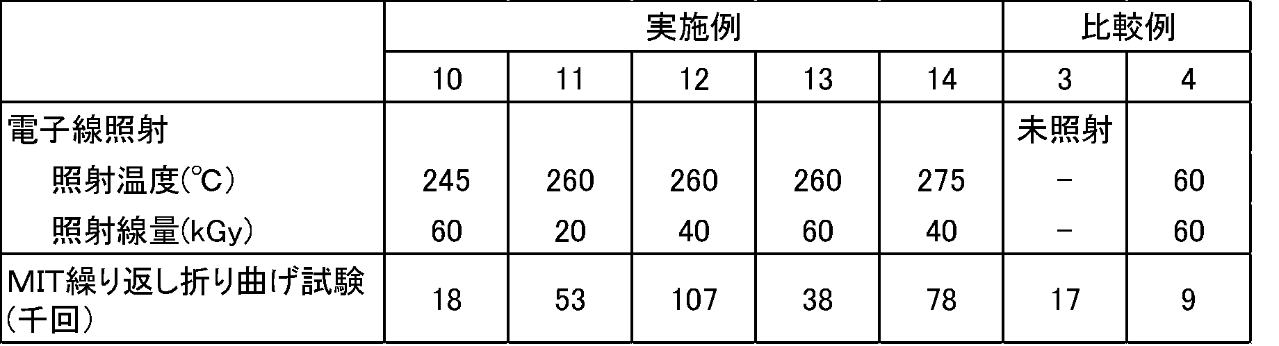
(実施例10~14、比較例3、4)
テトラフルオロエチレン(TFE)/パーフルオロ(プロピルビニルエーテル)(PAVE)共重合体[TFE/PAVE=99.9/0.1 (質量%)、MFR 0.1g/10分、融点320℃、ガラス転移温度105℃]を原料に用いた以外は、実施例1と同様にして、試験片を得た。
得られた試験片は、表2に記載の照射温度と照射線量で電子線照射を行った点以外は、実施例1と同様にしてMIT繰り返し折り曲げ試験を行った。結果を表2に示す。
テトラフルオロエチレン(TFE)/パーフルオロ(プロピルビニルエーテル)(PAVE)共重合体[TFE/PAVE=99.9/0.1 (質量%)、MFR 0.1g/10分、融点320℃、ガラス転移温度105℃]を原料に用いた以外は、実施例1と同様にして、試験片を得た。
得られた試験片は、表2に記載の照射温度と照射線量で電子線照射を行った点以外は、実施例1と同様にしてMIT繰り返し折り曲げ試験を行った。結果を表2に示す。
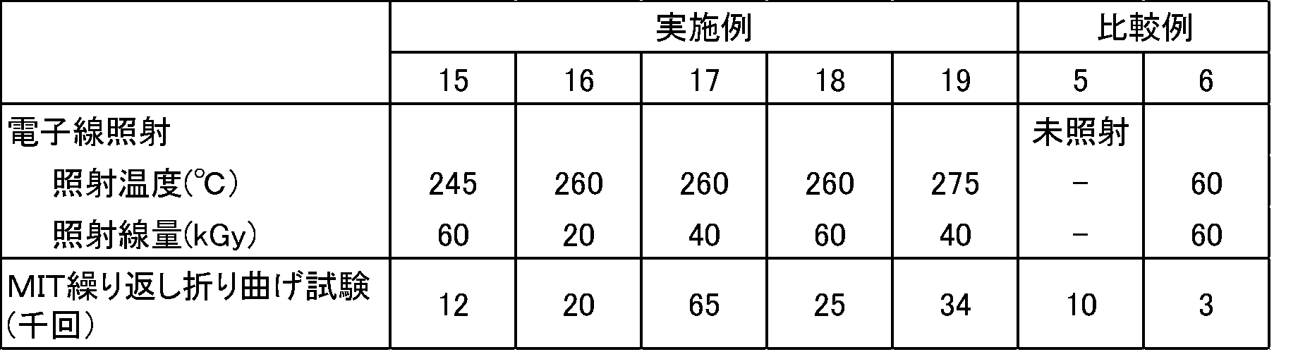
(実施例15~19、比較例5、6)
テトラフルオロエチレン(TFE)/パーフルオロ(プロピルビニルエーテル)(PAVE)共重合体[TFE/PAVE= 88/12(質量%)、MF40g/10分、融点260℃、ガラス転移温度80℃]を原料に用いた以外は、実施例1と同様にして、試験片を得た。
得られた試験片は、表3に記載の照射温度と照射線量で電子線照射を行った点以外は、実施例1と同様にしてMIT繰り返し折り曲げ試験を行った。結果を表3に示す。
テトラフルオロエチレン(TFE)/パーフルオロ(プロピルビニルエーテル)(PAVE)共重合体[TFE/PAVE= 88/12(質量%)、MF40g/10分、融点260℃、ガラス転移温度80℃]を原料に用いた以外は、実施例1と同様にして、試験片を得た。
得られた試験片は、表3に記載の照射温度と照射線量で電子線照射を行った点以外は、実施例1と同様にしてMIT繰り返し折り曲げ試験を行った。結果を表3に示す。
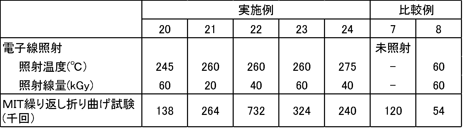
(実施例20~24、比較例7、8)
テトラフルオロエチレン(TFE)/パーフルオロ(プロピルビニルエーテル)(PAVE)共重合体[TFE/PAVE=94.5/5.5(質量%)、MFR12g/10分、融点302℃、ガラス転移温度93℃]を射出成形機で0.215mm厚のシート状に加工した後、幅12.5mm、長さ130mmの短冊状に切り取り、試験片を得た。
得られた試験片は、表4に記載の照射温度と照射線量で電子線照射を行った点以外は、実施例1と同様にしてMIT繰り返し折り曲げ試験を行った。結果を表4に示す。
テトラフルオロエチレン(TFE)/パーフルオロ(プロピルビニルエーテル)(PAVE)共重合体[TFE/PAVE=94.5/5.5(質量%)、MFR12g/10分、融点302℃、ガラス転移温度93℃]を射出成形機で0.215mm厚のシート状に加工した後、幅12.5mm、長さ130mmの短冊状に切り取り、試験片を得た。
得られた試験片は、表4に記載の照射温度と照射線量で電子線照射を行った点以外は、実施例1と同様にしてMIT繰り返し折り曲げ試験を行った。結果を表4に示す。
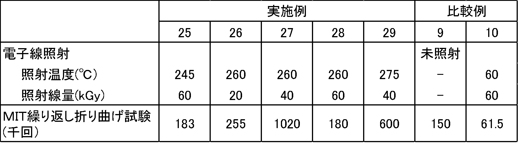
(実施例25~29、比較例9、10)
テトラフルオロエチレン(TFE)/パーフルオロ(プロピルビニルエーテル)(PAVE)共重合体[TFE/PAVE=94.5/5.5(質量%)、MFR3g/10分、融点302℃、ガラス転移温度93℃]を押出成型器で0.215mm厚のシート状に加工した後、幅12.5mm、長さ130mmの短冊状に切り取り、試験片を得た。
得られた試験片は、表5に記載の照射温度と照射線量で電子線照射を行った点以外は、実施例1と同様にしてMIT繰り返し折り曲げ試験を行った。結果を表5に示す。
テトラフルオロエチレン(TFE)/パーフルオロ(プロピルビニルエーテル)(PAVE)共重合体[TFE/PAVE=94.5/5.5(質量%)、MFR3g/10分、融点302℃、ガラス転移温度93℃]を押出成型器で0.215mm厚のシート状に加工した後、幅12.5mm、長さ130mmの短冊状に切り取り、試験片を得た。
得られた試験片は、表5に記載の照射温度と照射線量で電子線照射を行った点以外は、実施例1と同様にしてMIT繰り返し折り曲げ試験を行った。結果を表5に示す。

本発明の改質含フッ素共重合体からなる成形品は、ダイヤフラムポンプの隔膜部又はベローズ成形品等の耐クラック性が求められる各種の用途に適用することができる。
Claims (10)
- テトラフルオロエチレン単位及びパーフルオロ(アルキルビニルエーテル)単位のみからなる共重合体に、前記共重合体の融点以下、かつ、200℃以上の照射温度で、放射線を照射することにより得られた
ことを特徴とする改質含フッ素共重合体。 - 請求項1記載の改質含フッ素共重合体からなることを特徴とするフッ素樹脂成形品。
- テトラフルオロエチレン単位及びパーフルオロ(アルキルビニルエーテル)単位のみからなる共重合体を成形する工程、並びに、
成形された前記共重合体に、前記共重合体の融点以下、かつ、200℃以上の照射温度で、放射線を照射する工程を有する成形品の製造方法により得られた
ことを特徴とするフッ素樹脂成形品。 - 成形は、圧縮成形、射出成形又は押出成形である請求項3記載のフッ素樹脂成形品。
- シートである請求項2、3又は4記載のフッ素樹脂成形品。
- テトラフルオロエチレン単位及びパーフルオロ(アルキルビニルエーテル)単位のみからなる共重合体は、パーフルオロ(アルキルビニルエーテル)単位が全単量体単位の0.1~12質量%である請求項2、3、4又は5記載のフッ素樹脂成形品。
- テトラフルオロエチレン単位及びパーフルオロ(アルキルビニルエーテル)単位のみからなる共重合体の融点が280~322℃である請求項2、3、4、5又は6記載のフッ素樹脂成形品。
- パーフルオロ(アルキルビニルエーテル)は、パーフルオロ(プロピルビニルエーテル)である請求項2、3、4、5、6又は7記載のフッ素樹脂成形品。
- テトラフルオロエチレン単位及びパーフルオロ(アルキルビニルエーテル)単位のみからなる共重合体を成形する工程、並びに、
成形された前記共重合体に、前記共重合体の融点以下、かつ、200℃以上の照射温度で、放射線を照射する工程を有する
ことを特徴とするフッ素樹脂成形品の製造方法。 - 放射線の照射線量が10kGy~250kGyである請求項9記載のフッ素樹脂成形品の製造方法。
Priority Applications (2)
| Application Number | Priority Date | Filing Date | Title |
|---|---|---|---|
| US14/412,525 US10731015B2 (en) | 2012-07-05 | 2013-07-04 | Modified fluorine-containing copolymer, fluorine resin molded article, and method for manufacturing fluorine resin molded article |
| CN201380035372.1A CN104411752B (zh) | 2012-07-05 | 2013-07-04 | 改性含氟共聚物、氟树脂成型品以及氟树脂成型品的制造方法 |
Applications Claiming Priority (2)
| Application Number | Priority Date | Filing Date | Title |
|---|---|---|---|
| JP2012-151826 | 2012-07-05 | ||
| JP2012151826 | 2012-07-05 |
Publications (1)
| Publication Number | Publication Date |
|---|---|
| WO2014007346A1 true WO2014007346A1 (ja) | 2014-01-09 |
Family
ID=49882097
Family Applications (1)
| Application Number | Title | Priority Date | Filing Date |
|---|---|---|---|
| PCT/JP2013/068418 Ceased WO2014007346A1 (ja) | 2012-07-05 | 2013-07-04 | 改質含フッ素共重合体、フッ素樹脂成形品、及び、フッ素樹脂成形品の製造方法 |
Country Status (5)
| Country | Link |
|---|---|
| US (1) | US10731015B2 (ja) |
| JP (1) | JP5454726B2 (ja) |
| CN (1) | CN104411752B (ja) |
| TW (1) | TWI504645B (ja) |
| WO (1) | WO2014007346A1 (ja) |
Cited By (16)
| Publication number | Priority date | Publication date | Assignee | Title |
|---|---|---|---|---|
| WO2015104975A1 (ja) * | 2014-01-08 | 2015-07-16 | ダイキン工業株式会社 | 改質含フッ素共重合体及びフッ素樹脂成形品 |
| WO2018034238A1 (ja) * | 2016-08-16 | 2018-02-22 | ダイキン工業株式会社 | 成形品及び成形品の製造方法 |
| WO2020204163A1 (ja) * | 2019-04-05 | 2020-10-08 | ダイキン工業株式会社 | 電気化学デバイス用被圧縮部材 |
| JP7104363B1 (ja) | 2021-02-26 | 2022-07-21 | ダイキン工業株式会社 | 共重合体、成形体、押出成形体、ブロー成形体、トランスファー成形体および被覆電線 |
| US12318973B2 (en) | 2019-08-26 | 2025-06-03 | Daikin Industries, Ltd. | Injection molding method |
| US12381255B2 (en) | 2019-08-26 | 2025-08-05 | Daikin Industries, Ltd. | Member for nonaqueous electrolyte batteries |
| US12459176B2 (en) | 2021-02-26 | 2025-11-04 | Daikin Industries, Ltd. | Injection-molded body and production method therefor |
| US12459175B2 (en) | 2021-02-26 | 2025-11-04 | Daikin Industries, Ltd. | Injection-molded body and production method therefor |
| US12459174B2 (en) | 2021-02-26 | 2025-11-04 | Daikin Industries, Ltd. | Injection-molded body and production method therefor |
| US12459177B2 (en) | 2021-02-26 | 2025-11-04 | Daikin Industries, Ltd. | Injection-molded body and production method therefor |
| US12467572B2 (en) | 2021-02-26 | 2025-11-11 | Daikin Industries, Ltd. | Pipe joint and manufacturing method of pipe joint |
| US12540208B2 (en) | 2021-02-26 | 2026-02-03 | Daikin Industries, Ltd. | Copolymer, molded body, injection molded body, and coated electrical wire |
| US12539653B2 (en) | 2021-02-26 | 2026-02-03 | Daikin Industries, Ltd. | Injection molded article |
| US12555826B2 (en) | 2019-08-26 | 2026-02-17 | Daikin Industries, Ltd. | Member for nonaqueous electrolyte batteries |
| US12603368B2 (en) | 2019-08-26 | 2026-04-14 | Daikin Industries, Ltd. | Member for nonaqueous electrolyte batteries |
| US12614795B2 (en) | 2019-08-26 | 2026-04-28 | Daikin Industries, Ltd. | Power storage assembly and gasket |
Families Citing this family (18)
| Publication number | Priority date | Publication date | Assignee | Title |
|---|---|---|---|---|
| WO2015152310A1 (ja) * | 2014-03-31 | 2015-10-08 | ダイキン工業株式会社 | 成形体およびその製造方法 |
| KR102554153B1 (ko) * | 2015-09-07 | 2023-07-10 | 스미토모덴코파인폴리머 가부시키가이샤 | 폴리테트라플루오로에틸렌 성형체의 제조 방법 및 폴리테트라플루오로에틸렌 성형체 |
| JP6750172B2 (ja) * | 2015-09-07 | 2020-09-02 | 住友電工ファインポリマー株式会社 | 摺動部材に用いられるポリテトラフルオロエチレン成形体及びその製造方法 |
| JP7001384B2 (ja) * | 2016-08-10 | 2022-01-19 | キヤノン株式会社 | 電子写真用ベルトの製造方法 |
| JP6369511B2 (ja) * | 2016-08-30 | 2018-08-08 | ダイキン工業株式会社 | 改質成形品の製造方法、成形品、ダイヤフラム及びダイヤフラムバルブ |
| WO2018216284A1 (ja) * | 2017-05-22 | 2018-11-29 | ダイキン工業株式会社 | 極低温シール材 |
| JP7348483B2 (ja) * | 2018-07-12 | 2023-09-21 | ダイキン工業株式会社 | 成形品の製造方法および成形品 |
| JP6870721B2 (ja) * | 2018-11-27 | 2021-05-12 | ダイキン工業株式会社 | フッ素樹脂成形品の製造方法および製造システム |
| CN113710732B (zh) * | 2019-04-26 | 2025-10-28 | 大金工业株式会社 | 电磁线和线圈 |
| KR102788190B1 (ko) * | 2019-11-27 | 2025-03-31 | 다이킨 고교 가부시키가이샤 | 복합 재료의 제조 방법 |
| JP7044994B1 (ja) * | 2020-09-30 | 2022-03-31 | ダイキン工業株式会社 | 共重合体、射出成形体、被圧縮部材および被覆電線 |
| CN116964138A (zh) * | 2021-02-12 | 2023-10-27 | 大金工业株式会社 | 改性氟树脂材料、电路基板用材料、电路基板用层积体、电路基板以及改性氟树脂材料的制造方法 |
| CN116888172A (zh) * | 2021-02-26 | 2023-10-13 | 大金工业株式会社 | 共聚物、成型体、挤出成型体、吹塑成型体、传递成型体以及被覆电线 |
| CN116867816A (zh) * | 2021-02-26 | 2023-10-10 | 大金工业株式会社 | 共聚物、成型体、注射成型体和被覆电线 |
| US12232851B2 (en) | 2021-03-08 | 2025-02-25 | Medtronic, Inc. | Acute health event monitoring |
| US11633112B2 (en) | 2021-03-08 | 2023-04-25 | Medtronic, Inc. | Automatic alert control for acute health event |
| US12558036B2 (en) | 2021-03-08 | 2026-02-24 | Medtronic, Inc. | Acute health event monitoring and verification |
| JP7525810B2 (ja) * | 2022-10-28 | 2024-07-31 | ダイキン工業株式会社 | ダイヤフラムおよびダイヤフラムバルブ |
Citations (6)
| Publication number | Priority date | Publication date | Assignee | Title |
|---|---|---|---|---|
| JPH1149867A (ja) * | 1997-07-31 | 1999-02-23 | Japan Atom Energy Res Inst | 改質フッ素樹脂およびその製造方法 |
| JP2000186162A (ja) * | 1998-12-22 | 2000-07-04 | Hitachi Cable Ltd | 改質フッ素樹脂の製造方法 |
| JP2002284893A (ja) * | 2001-03-26 | 2002-10-03 | Hitachi Cable Ltd | 改質ふっ素樹脂の製造方法および装置 |
| JP2003165853A (ja) * | 2001-11-30 | 2003-06-10 | Sumitomo Heavy Ind Ltd | 改質フッ素樹脂及びそれを用いた部材の製造方法 |
| JP2007137982A (ja) * | 2005-11-17 | 2007-06-07 | Japan Atomic Energy Agency | 放射線架橋含フッ素共重合体 |
| JP2010155443A (ja) * | 2009-01-05 | 2010-07-15 | Sumitomo Electric Fine Polymer Inc | 架橋フッ素樹脂複合材料の製造方法 |
Family Cites Families (14)
| Publication number | Priority date | Publication date | Assignee | Title |
|---|---|---|---|---|
| JP3836255B2 (ja) | 1998-06-10 | 2006-10-25 | 株式会社レイテック | 改質フッ素樹脂の製造方法 |
| JP4665149B2 (ja) | 2000-07-19 | 2011-04-06 | 独立行政法人 日本原子力研究開発機構 | 改質フッ素樹脂成形体を製造する方法 |
| JP3730533B2 (ja) | 2001-05-02 | 2006-01-05 | 日本原子力研究所 | フッ素樹脂の改質方法 |
| JP2002338766A (ja) | 2001-05-21 | 2002-11-27 | Hitachi Cable Ltd | 改質ふっ素樹脂組成物 |
| JP3731536B2 (ja) | 2001-12-25 | 2006-01-05 | 日立電線株式会社 | 架橋テトラフルオロエチレン/ヘキサフルオロプロピレン系共重合体微粉末及びその製造方法 |
| JP3952865B2 (ja) | 2002-06-05 | 2007-08-01 | 日立電線株式会社 | 塗装材料および塗装材料を用いた塗装膜の形成方法 |
| JP2005113116A (ja) | 2003-09-16 | 2005-04-28 | Reitekku:Kk | テトラフルオロエチレンポリマーアロイおよびその製造方法 |
| CN1900154A (zh) * | 2005-07-01 | 2007-01-24 | 株式会社西铁城电子 | 生产耐热带电氟树脂材料的方法和使用该材料生产驻极体电容麦克风的方法 |
| CN100489026C (zh) * | 2005-12-16 | 2009-05-20 | 日立电线株式会社 | 改性氟树脂组合物及成型体 |
| JP5224315B2 (ja) | 2007-03-23 | 2013-07-03 | 独立行政法人日本原子力研究開発機構 | 放射線架橋含フッ素共重合体 |
| JP5224314B2 (ja) | 2007-03-23 | 2013-07-03 | 独立行政法人日本原子力研究開発機構 | 放射線架橋含フッ素共重合体 |
| JP2011105012A (ja) | 2011-02-17 | 2011-06-02 | Raytech Corp | 改質フッ素樹脂被覆材およびその製造方法 |
| JP5598579B2 (ja) | 2012-07-05 | 2014-10-01 | ダイキン工業株式会社 | 改質フッ素樹脂混合物、フッ素樹脂成形品、及び、フッ素樹脂成形品の製造方法 |
| JP5392433B1 (ja) | 2012-07-05 | 2014-01-22 | ダイキン工業株式会社 | 改質含フッ素共重合体、フッ素樹脂成形品、及び、フッ素樹脂成形品の製造方法 |
-
2013
- 2013-07-04 WO PCT/JP2013/068418 patent/WO2014007346A1/ja not_active Ceased
- 2013-07-04 JP JP2013140829A patent/JP5454726B2/ja active Active
- 2013-07-04 US US14/412,525 patent/US10731015B2/en active Active
- 2013-07-04 CN CN201380035372.1A patent/CN104411752B/zh active Active
- 2013-07-05 TW TW102124190A patent/TWI504645B/zh active
Patent Citations (6)
| Publication number | Priority date | Publication date | Assignee | Title |
|---|---|---|---|---|
| JPH1149867A (ja) * | 1997-07-31 | 1999-02-23 | Japan Atom Energy Res Inst | 改質フッ素樹脂およびその製造方法 |
| JP2000186162A (ja) * | 1998-12-22 | 2000-07-04 | Hitachi Cable Ltd | 改質フッ素樹脂の製造方法 |
| JP2002284893A (ja) * | 2001-03-26 | 2002-10-03 | Hitachi Cable Ltd | 改質ふっ素樹脂の製造方法および装置 |
| JP2003165853A (ja) * | 2001-11-30 | 2003-06-10 | Sumitomo Heavy Ind Ltd | 改質フッ素樹脂及びそれを用いた部材の製造方法 |
| JP2007137982A (ja) * | 2005-11-17 | 2007-06-07 | Japan Atomic Energy Agency | 放射線架橋含フッ素共重合体 |
| JP2010155443A (ja) * | 2009-01-05 | 2010-07-15 | Sumitomo Electric Fine Polymer Inc | 架橋フッ素樹脂複合材料の製造方法 |
Cited By (26)
| Publication number | Priority date | Publication date | Assignee | Title |
|---|---|---|---|---|
| JP2015147924A (ja) * | 2014-01-08 | 2015-08-20 | ダイキン工業株式会社 | 改質含フッ素共重合体及びフッ素樹脂成形品 |
| WO2015104975A1 (ja) * | 2014-01-08 | 2015-07-16 | ダイキン工業株式会社 | 改質含フッ素共重合体及びフッ素樹脂成形品 |
| US11826975B2 (en) | 2016-08-16 | 2023-11-28 | Daikin Industries, Ltd. | Molded article and manufacturing method for molded article |
| WO2018034238A1 (ja) * | 2016-08-16 | 2018-02-22 | ダイキン工業株式会社 | 成形品及び成形品の製造方法 |
| JP2018028082A (ja) * | 2016-08-16 | 2018-02-22 | ダイキン工業株式会社 | 成形品及び成形品の製造方法 |
| KR20190040005A (ko) * | 2016-08-16 | 2019-04-16 | 다이킨 고교 가부시키가이샤 | 성형품 및 성형품의 제조 방법 |
| KR101996788B1 (ko) | 2016-08-16 | 2019-07-04 | 다이킨 고교 가부시키가이샤 | 성형품 및 성형품의 제조 방법 |
| WO2020204163A1 (ja) * | 2019-04-05 | 2020-10-08 | ダイキン工業株式会社 | 電気化学デバイス用被圧縮部材 |
| JP7299525B2 (ja) | 2019-04-05 | 2023-06-28 | ダイキン工業株式会社 | 電気化学デバイス用被圧縮部材 |
| JPWO2020204163A1 (ja) * | 2019-04-05 | 2020-10-08 | ||
| US12381255B2 (en) | 2019-08-26 | 2025-08-05 | Daikin Industries, Ltd. | Member for nonaqueous electrolyte batteries |
| US12614795B2 (en) | 2019-08-26 | 2026-04-28 | Daikin Industries, Ltd. | Power storage assembly and gasket |
| US12603368B2 (en) | 2019-08-26 | 2026-04-14 | Daikin Industries, Ltd. | Member for nonaqueous electrolyte batteries |
| US12555826B2 (en) | 2019-08-26 | 2026-02-17 | Daikin Industries, Ltd. | Member for nonaqueous electrolyte batteries |
| US12318973B2 (en) | 2019-08-26 | 2025-06-03 | Daikin Industries, Ltd. | Injection molding method |
| US12459176B2 (en) | 2021-02-26 | 2025-11-04 | Daikin Industries, Ltd. | Injection-molded body and production method therefor |
| JP7104363B1 (ja) | 2021-02-26 | 2022-07-21 | ダイキン工業株式会社 | 共重合体、成形体、押出成形体、ブロー成形体、トランスファー成形体および被覆電線 |
| US12459175B2 (en) | 2021-02-26 | 2025-11-04 | Daikin Industries, Ltd. | Injection-molded body and production method therefor |
| US12459174B2 (en) | 2021-02-26 | 2025-11-04 | Daikin Industries, Ltd. | Injection-molded body and production method therefor |
| US12459177B2 (en) | 2021-02-26 | 2025-11-04 | Daikin Industries, Ltd. | Injection-molded body and production method therefor |
| US12467572B2 (en) | 2021-02-26 | 2025-11-11 | Daikin Industries, Ltd. | Pipe joint and manufacturing method of pipe joint |
| US12540208B2 (en) | 2021-02-26 | 2026-02-03 | Daikin Industries, Ltd. | Copolymer, molded body, injection molded body, and coated electrical wire |
| US12539653B2 (en) | 2021-02-26 | 2026-02-03 | Daikin Industries, Ltd. | Injection molded article |
| EP4299634A4 (en) * | 2021-02-26 | 2025-02-12 | Daikin Industries, Ltd. | COPOLYMER, MOLDED BODY, EXTRUDED BODY, BLOW MOLDED BODY, TRANSFER MOLDED BODY AND COATED ELECTRICAL WIRE |
| JP2022132122A (ja) * | 2021-02-26 | 2022-09-07 | ダイキン工業株式会社 | 共重合体、成形体、押出成形体、ブロー成形体、トランスファー成形体および被覆電線 |
| WO2022181241A1 (ja) * | 2021-02-26 | 2022-09-01 | ダイキン工業株式会社 | 共重合体、成形体、押出成形体、ブロー成形体、トランスファー成形体および被覆電線 |
Also Published As
| Publication number | Publication date |
|---|---|
| US20150158988A1 (en) | 2015-06-11 |
| JP2014028951A (ja) | 2014-02-13 |
| CN104411752B (zh) | 2017-06-23 |
| JP5454726B2 (ja) | 2014-03-26 |
| CN104411752A (zh) | 2015-03-11 |
| US10731015B2 (en) | 2020-08-04 |
| TW201412833A (zh) | 2014-04-01 |
| TWI504645B (zh) | 2015-10-21 |
Similar Documents
| Publication | Publication Date | Title |
|---|---|---|
| JP5454726B2 (ja) | 改質含フッ素共重合体、フッ素樹脂成形品、及び、フッ素樹脂成形品の製造方法 | |
| JP5598579B2 (ja) | 改質フッ素樹脂混合物、フッ素樹脂成形品、及び、フッ素樹脂成形品の製造方法 | |
| JP5392433B1 (ja) | 改質含フッ素共重合体、フッ素樹脂成形品、及び、フッ素樹脂成形品の製造方法 | |
| JP5967181B2 (ja) | 改質含フッ素共重合体及びフッ素樹脂成形品 | |
| JP5962873B2 (ja) | フッ素樹脂の改質成形品の製造方法 | |
| JP6045559B2 (ja) | 耐熱電線 | |
| US11826975B2 (en) | Molded article and manufacturing method for molded article | |
| JP6369511B2 (ja) | 改質成形品の製造方法、成形品、ダイヤフラム及びダイヤフラムバルブ | |
| JP7060832B2 (ja) | 成形品およびその製造方法、ダイヤフラムおよびダイヤフラムバルブ | |
| JP5224315B2 (ja) | 放射線架橋含フッ素共重合体 | |
| JP5224314B2 (ja) | 放射線架橋含フッ素共重合体 |
Legal Events
| Date | Code | Title | Description |
|---|---|---|---|
| 121 | Ep: the epo has been informed by wipo that ep was designated in this application |
Ref document number: 13813737 Country of ref document: EP Kind code of ref document: A1 |
|
| WWE | Wipo information: entry into national phase |
Ref document number: 14412525 Country of ref document: US |
|
| NENP | Non-entry into the national phase |
Ref country code: DE |
|
| 122 | Ep: pct application non-entry in european phase |
Ref document number: 13813737 Country of ref document: EP Kind code of ref document: A1 |