WO2013141403A1 - Système de pile à combustible à oxyde solide - Google Patents
Système de pile à combustible à oxyde solide Download PDFInfo
- Publication number
- WO2013141403A1 WO2013141403A1 PCT/JP2013/058614 JP2013058614W WO2013141403A1 WO 2013141403 A1 WO2013141403 A1 WO 2013141403A1 JP 2013058614 W JP2013058614 W JP 2013058614W WO 2013141403 A1 WO2013141403 A1 WO 2013141403A1
- Authority
- WO
- WIPO (PCT)
- Prior art keywords
- fuel
- fuel cell
- electrode side
- temperature
- pressure
- Prior art date
Links
Images


Classifications
-
- H—ELECTRICITY
- H01—ELECTRIC ELEMENTS
- H01M—PROCESSES OR MEANS, e.g. BATTERIES, FOR THE DIRECT CONVERSION OF CHEMICAL ENERGY INTO ELECTRICAL ENERGY
- H01M8/00—Fuel cells; Manufacture thereof
- H01M8/06—Combination of fuel cells with means for production of reactants or for treatment of residues
- H01M8/0606—Combination of fuel cells with means for production of reactants or for treatment of residues with means for production of gaseous reactants
- H01M8/0612—Combination of fuel cells with means for production of reactants or for treatment of residues with means for production of gaseous reactants from carbon-containing material
- H01M8/0618—Reforming processes, e.g. autothermal, partial oxidation or steam reforming
-
- H—ELECTRICITY
- H01—ELECTRIC ELEMENTS
- H01M—PROCESSES OR MEANS, e.g. BATTERIES, FOR THE DIRECT CONVERSION OF CHEMICAL ENERGY INTO ELECTRICAL ENERGY
- H01M8/00—Fuel cells; Manufacture thereof
- H01M8/04—Auxiliary arrangements, e.g. for control of pressure or for circulation of fluids
- H01M8/04223—Auxiliary arrangements, e.g. for control of pressure or for circulation of fluids during start-up or shut-down; Depolarisation or activation, e.g. purging; Means for short-circuiting defective fuel cells
- H01M8/04225—Auxiliary arrangements, e.g. for control of pressure or for circulation of fluids during start-up or shut-down; Depolarisation or activation, e.g. purging; Means for short-circuiting defective fuel cells during start-up
-
- H—ELECTRICITY
- H01—ELECTRIC ELEMENTS
- H01M—PROCESSES OR MEANS, e.g. BATTERIES, FOR THE DIRECT CONVERSION OF CHEMICAL ENERGY INTO ELECTRICAL ENERGY
- H01M8/00—Fuel cells; Manufacture thereof
- H01M8/04—Auxiliary arrangements, e.g. for control of pressure or for circulation of fluids
- H01M8/04223—Auxiliary arrangements, e.g. for control of pressure or for circulation of fluids during start-up or shut-down; Depolarisation or activation, e.g. purging; Means for short-circuiting defective fuel cells
- H01M8/04228—Auxiliary arrangements, e.g. for control of pressure or for circulation of fluids during start-up or shut-down; Depolarisation or activation, e.g. purging; Means for short-circuiting defective fuel cells during shut-down
-
- H—ELECTRICITY
- H01—ELECTRIC ELEMENTS
- H01M—PROCESSES OR MEANS, e.g. BATTERIES, FOR THE DIRECT CONVERSION OF CHEMICAL ENERGY INTO ELECTRICAL ENERGY
- H01M8/00—Fuel cells; Manufacture thereof
- H01M8/04—Auxiliary arrangements, e.g. for control of pressure or for circulation of fluids
- H01M8/04298—Processes for controlling fuel cells or fuel cell systems
- H01M8/043—Processes for controlling fuel cells or fuel cell systems applied during specific periods
- H01M8/04302—Processes for controlling fuel cells or fuel cell systems applied during specific periods applied during start-up
-
- H—ELECTRICITY
- H01—ELECTRIC ELEMENTS
- H01M—PROCESSES OR MEANS, e.g. BATTERIES, FOR THE DIRECT CONVERSION OF CHEMICAL ENERGY INTO ELECTRICAL ENERGY
- H01M8/00—Fuel cells; Manufacture thereof
- H01M8/04—Auxiliary arrangements, e.g. for control of pressure or for circulation of fluids
- H01M8/04298—Processes for controlling fuel cells or fuel cell systems
- H01M8/043—Processes for controlling fuel cells or fuel cell systems applied during specific periods
- H01M8/04303—Processes for controlling fuel cells or fuel cell systems applied during specific periods applied during shut-down
-
- H—ELECTRICITY
- H01—ELECTRIC ELEMENTS
- H01M—PROCESSES OR MEANS, e.g. BATTERIES, FOR THE DIRECT CONVERSION OF CHEMICAL ENERGY INTO ELECTRICAL ENERGY
- H01M8/00—Fuel cells; Manufacture thereof
- H01M8/04—Auxiliary arrangements, e.g. for control of pressure or for circulation of fluids
- H01M8/04298—Processes for controlling fuel cells or fuel cell systems
- H01M8/04313—Processes for controlling fuel cells or fuel cell systems characterised by the detection or assessment of variables; characterised by the detection or assessment of failure or abnormal function
- H01M8/0432—Temperature; Ambient temperature
-
- H—ELECTRICITY
- H01—ELECTRIC ELEMENTS
- H01M—PROCESSES OR MEANS, e.g. BATTERIES, FOR THE DIRECT CONVERSION OF CHEMICAL ENERGY INTO ELECTRICAL ENERGY
- H01M8/00—Fuel cells; Manufacture thereof
- H01M8/04—Auxiliary arrangements, e.g. for control of pressure or for circulation of fluids
- H01M8/04298—Processes for controlling fuel cells or fuel cell systems
- H01M8/04694—Processes for controlling fuel cells or fuel cell systems characterised by variables to be controlled
- H01M8/04746—Pressure; Flow
- H01M8/04753—Pressure; Flow of fuel cell reactants
-
- H—ELECTRICITY
- H01—ELECTRIC ELEMENTS
- H01M—PROCESSES OR MEANS, e.g. BATTERIES, FOR THE DIRECT CONVERSION OF CHEMICAL ENERGY INTO ELECTRICAL ENERGY
- H01M8/00—Fuel cells; Manufacture thereof
- H01M8/24—Grouping of fuel cells, e.g. stacking of fuel cells
- H01M8/241—Grouping of fuel cells, e.g. stacking of fuel cells with solid or matrix-supported electrolytes
- H01M8/2425—High-temperature cells with solid electrolytes
- H01M8/2428—Grouping by arranging unit cells on a surface of any form, e.g. planar or tubular
-
- H—ELECTRICITY
- H01—ELECTRIC ELEMENTS
- H01M—PROCESSES OR MEANS, e.g. BATTERIES, FOR THE DIRECT CONVERSION OF CHEMICAL ENERGY INTO ELECTRICAL ENERGY
- H01M8/00—Fuel cells; Manufacture thereof
- H01M8/24—Grouping of fuel cells, e.g. stacking of fuel cells
- H01M8/241—Grouping of fuel cells, e.g. stacking of fuel cells with solid or matrix-supported electrolytes
- H01M8/2425—High-temperature cells with solid electrolytes
- H01M8/243—Grouping of unit cells of tubular or cylindrical configuration
-
- H—ELECTRICITY
- H01—ELECTRIC ELEMENTS
- H01M—PROCESSES OR MEANS, e.g. BATTERIES, FOR THE DIRECT CONVERSION OF CHEMICAL ENERGY INTO ELECTRICAL ENERGY
- H01M8/00—Fuel cells; Manufacture thereof
- H01M8/24—Grouping of fuel cells, e.g. stacking of fuel cells
- H01M8/2457—Grouping of fuel cells, e.g. stacking of fuel cells with both reactants being gaseous or vaporised
-
- H—ELECTRICITY
- H01—ELECTRIC ELEMENTS
- H01M—PROCESSES OR MEANS, e.g. BATTERIES, FOR THE DIRECT CONVERSION OF CHEMICAL ENERGY INTO ELECTRICAL ENERGY
- H01M8/00—Fuel cells; Manufacture thereof
- H01M8/24—Grouping of fuel cells, e.g. stacking of fuel cells
- H01M8/2465—Details of groupings of fuel cells
- H01M8/2484—Details of groupings of fuel cells characterised by external manifolds
-
- H—ELECTRICITY
- H01—ELECTRIC ELEMENTS
- H01M—PROCESSES OR MEANS, e.g. BATTERIES, FOR THE DIRECT CONVERSION OF CHEMICAL ENERGY INTO ELECTRICAL ENERGY
- H01M8/00—Fuel cells; Manufacture thereof
- H01M8/10—Fuel cells with solid electrolytes
- H01M8/12—Fuel cells with solid electrolytes operating at high temperature, e.g. with stabilised ZrO2 electrolyte
- H01M2008/1293—Fuel cells with solid oxide electrolytes
-
- H—ELECTRICITY
- H01—ELECTRIC ELEMENTS
- H01M—PROCESSES OR MEANS, e.g. BATTERIES, FOR THE DIRECT CONVERSION OF CHEMICAL ENERGY INTO ELECTRICAL ENERGY
- H01M8/00—Fuel cells; Manufacture thereof
- H01M8/04—Auxiliary arrangements, e.g. for control of pressure or for circulation of fluids
- H01M8/04082—Arrangements for control of reactant parameters, e.g. pressure or concentration
- H01M8/04089—Arrangements for control of reactant parameters, e.g. pressure or concentration of gaseous reactants
- H01M8/04104—Regulation of differential pressures
-
- Y—GENERAL TAGGING OF NEW TECHNOLOGICAL DEVELOPMENTS; GENERAL TAGGING OF CROSS-SECTIONAL TECHNOLOGIES SPANNING OVER SEVERAL SECTIONS OF THE IPC; TECHNICAL SUBJECTS COVERED BY FORMER USPC CROSS-REFERENCE ART COLLECTIONS [XRACs] AND DIGESTS
- Y02—TECHNOLOGIES OR APPLICATIONS FOR MITIGATION OR ADAPTATION AGAINST CLIMATE CHANGE
- Y02E—REDUCTION OF GREENHOUSE GAS [GHG] EMISSIONS, RELATED TO ENERGY GENERATION, TRANSMISSION OR DISTRIBUTION
- Y02E60/00—Enabling technologies; Technologies with a potential or indirect contribution to GHG emissions mitigation
- Y02E60/30—Hydrogen technology
- Y02E60/50—Fuel cells
Definitions
- the present invention relates to a solid oxide fuel cell system, and more particularly to a solid oxide fuel cell system that generates electric power by reacting hydrogen generated by steam reforming of fuel with an oxidant gas.
- Solid Oxide Fuel Cell uses an oxide ion conductive solid electrolyte as an electrolyte, has electrodes on both sides, and supplies fuel gas on one side.
- the fuel cell operates at a relatively high temperature by supplying an oxidant (air, oxygen, etc.) to the other side.
- Patent Document 1 JP 2012-3850 A (Patent Document 1) describes a solid oxide fuel cell.
- this fuel cell when stopping a fuel cell operating at a high temperature, supplying a small amount of fuel and water for fuel reforming while supplying air to the air electrode side of the fuel cell stack, Due to the cooling effect of the air, the temperature in the fuel cell module is lowered. That is, in this fuel cell, first, in the stopping step, the fuel cell stack is formed by sending a large amount of cooling air while continuing to supply fuel even after the extraction of power from the fuel cell module is stopped. Cool down. Next, supply of fuel is stopped when the temperature of the cell stack drops below the oxidation temperature of the fuel cell. After that, only the cooling air is supplied until the temperature drops sufficiently, and the fuel cell is safely stopped. I am letting.
- the so-called shutdown stop is performed in which the extraction of electric power and the supply of fuel, water for fuel reforming, and power generation air (air sent to the air electrode side) are completely stopped in a short time.
- Fuel cells are also known.
- Patent Document 2 describes a fuel cell system. In this fuel cell system, at the time of an emergency stop, a delivery pump that supplies fuel to the reformer, a reforming water pump that supplies water for steam reforming, and an air blower that sends air to the air electrode side of the cell stack Stop.
- the fuel gas adsorbed in the adsorber is in a state where the supply of the fuel gas from the fuel supply source is shut off. Is sent to the reformer, and steam reforming is performed by the water supplied from the reforming water pump. Thereby, even after the supply of the fuel gas is interrupted, the reformed fuel is supplied to the fuel electrode of the cell stack for a predetermined period, and the oxidation of the fuel electrode due to the backflow of air is prevented.
- Patent Document 3 Japanese Unexamined Patent Application Publication No. 2012-138186 (Patent Document 3) describes a high-temperature operating fuel cell system.
- the raw fuel pump that supplies fuel gas is stopped, while the reforming water pump that supplies water to the reformer is operated.
- the reforming water pump is operated, the supplied water expands in volume by being evaporated in the reformer.
- the fuel gas remaining in the fuel gas supply line downstream of the reformer is expanded by the pressure of the volume-expanded water vapor. Is pushed out to the fuel cell (cell stack) side. Thereby, the oxidation of the fuel electrode due to the backflow of air is prevented.
- Patent Document 1 fuel is supplied until the fuel cell stack is lowered to a predetermined temperature even during the stop process, so that fuel that does not contribute to power generation is wasted. There is a problem of being.
- the cooling air supplied to the air electrode side of the fuel battery cell flows backward to the fuel electrode side, The backflowed air oxidizes the fuel electrode of the fuel cell and damages the cell. For this reason, it is necessary to continue supplying the fuel until the temperature of the fuel cell falls below the oxidation temperature, and to prevent the backflow of the cooling air supplied to the air electrode side of the fuel cell.
- the time until the temperature of the fuel cell stack that has been operating falls below the oxidation temperature in the stop process depends on the heat insulation performance of the fuel cell module, etc. It is necessary to continue supplying fuel that does not contribute to power generation over time.
- the shutdown stop fuel and water for fuel reforming are completely stopped in a short time, so that waste of fuel can be suppressed. Further, in the shutdown stop, the fuel cell stack is stopped in a high temperature state, so that the fuel supply is stopped, so that the supply of cooling air to be sent to the air electrode side of the fuel cell stack is stopped together with the fuel supply stop, Backflow of air to the fuel electrode side and oxidation of the fuel electrode are avoided.
- the present inventor oxidizes the fuel electrode of the fuel cell and deteriorates the cell even if the air sent to the air electrode side of the fuel cell stack is stopped when the fuel supply is stopped. And found a new technical problem that leads to cell damage.
- Patent Document 2 Japanese Patent Application Laid-Open No. 2010-27579
- the delivery pump is operated to be adsorbed by the adsorber for a certain period.
- the spent fuel gas can be sent to the cell stack to prevent oxidation of the fuel electrode.
- it is necessary to provide a special adsorber in order to store the fuel in advance.
- the heat capacity of a fuel cell is extremely large, it takes a long time to decrease to a temperature at which oxidation of the fuel electrode can be avoided, and a large amount of fuel that continues to be supplied over this long time is adsorbed to the adsorber. It is difficult to let it go.
- an object of the present invention is to provide a solid oxide fuel cell system capable of executing shutdown stop while sufficiently suppressing oxidation of the fuel cell.
- the present invention provides a solid oxide fuel cell system that generates power by reacting hydrogen generated by steam reforming a fuel and an oxidant gas, and comprising a fuel cell stack.
- a fuel cell module a fuel supply device for supplying fuel to the fuel cell module, a water supply device for supplying water for steam reforming to the fuel cell module, and an oxidant gas electrode side of the fuel cell stack
- An oxidant gas supply device that supplies an oxidant gas
- a reformer that is disposed in the fuel cell module and reforms the fuel supplied from the fuel supply device with water vapor using the water supplied from the water supply device
- An exhaust gas passage and a fuel supply device, a water supply device, an oxidant gas supply device, and a controller that controls the extraction of electric power from the fuel cell module.
- the controller stops fuel supply, water supply, and power generation.
- the fuel / exhaust gas passage has a predetermined oxidation that reduces the risk that the temperature of the fuel electrode is oxidized after the shutdown stop is executed by the shutdown stop circuit.
- Mechanical pressure that maintains the pressure on the oxidant gas electrode side in the fuel cell module higher than atmospheric pressure and maintains the pressure on the fuel electrode side higher than the pressure on the oxidant gas electrode side until the temperature decreases to the suppression temperature. It is configured to function as holding means.
- fuel and water are respectively supplied to the reformer disposed in the fuel cell module by the fuel supply device and the water supply device, and the reformer converts the fuel into steam reforming.
- the reformed fuel is supplied to the fuel electrode side of each fuel cell unit constituting the fuel cell stack.
- the oxidant gas is supplied to the oxidant gas electrode side of the fuel cell stack by the oxidant gas supply device.
- the fuel / exhaust gas passage guides the fuel / exhaust gas from the fuel supply device to the outside of the fuel cell module through the fuel electrode of each fuel cell unit constituting the reformer and the fuel cell stack.
- the controller includes a shutdown stop circuit and controls the extraction of electric power from the fuel supply device, the water supply device, the oxidant gas supply device, and the fuel cell module.
- the fuel / exhaust gas passage functions as a mechanical pressure holding means, and after the fuel supply, water supply, and power generation are stopped by the shutdown stop circuit, the temperature of the fuel electrode decreases the risk of the fuel electrode being oxidized.
- the pressure on the oxidant gas electrode side in the fuel cell module is maintained higher than the atmospheric pressure and the pressure on the fuel electrode side is maintained higher than the pressure on the oxidant gas electrode side until the temperature is reduced to a predetermined oxidation suppression temperature. To do.
- a conventional solid oxide fuel cell system when shutting down, supply of fuel, supply of water for fuel reforming, extraction of power from the fuel cell module, and supply of oxidant gas are all performed. Stop at the same time.
- the supply of the oxidant gas is stopped simultaneously with the stop of the fuel and power extraction, the fuel cell stack temperature is immediately higher than the oxidation temperature immediately after the power extraction stop, and the fuel is stopped. This is because when only the oxidant gas is supplied, the oxidant gas flows backward to the fuel electrode side of the fuel cell unit, and the fuel electrode may be damaged.
- the present inventors have found a new problem that the oxidant gas may oxidize the fuel electrode even when the supply of the oxidant gas is stopped simultaneously. This problem is caused by the occurrence of a temperature difference between the fuel electrode side and the oxidant gas electrode side of each fuel cell unit after stopping power extraction.
- the cooling effect by the oxidant gas is lost and the temperature tends to rise.
- the extraction of electric power is stopped on the fuel electrode side of each fuel cell unit, no heat is generated. The fuel remaining in the reformer and the like flows into the fuel electrode side of each fuel cell unit even after the fuel supply by the fuel supply means is stopped.
- the fuel flowing into the fuel electrode side is generated by a steam reforming reaction that is an endothermic reaction in the reformer, and is generally lower than the temperature on the oxidant gas electrode side of the fuel cell unit.
- the oxidant gas electrode side of each fuel cell unit tends to increase in temperature after stopping the fuel supply and power extraction, whereas the fuel electrode side loses power generation heat or has a low temperature.
- the temperature tends to decrease due to the inflow of the remaining fuel. In the portion where the temperature has decreased, the surrounding gas contracts and the pressure decreases, and in the portion where the temperature has increased, the surrounding gas expands and the pressure increases.
- the present inventor has solved this new technical problem by providing a mechanical pressure holding means. That is, the fuel / exhaust gas passage for guiding the fuel / exhaust gas from the fuel supply device to the outside of the fuel cell module through the fuel electrode of each fuel cell unit constituting the reformer and the fuel cell stack is mechanically provided. It was configured as a pressure holding means.
- the fuel passage is configured to reach the oxidant gas electrode side from the fuel supply device through the reformer and the fuel electrode of each fuel cell unit.
- the exhaust gas passage is configured to extend from the oxidant gas electrode side in the fuel cell module to the outside air outside the fuel cell module.
- the shutdown temperature is lowered to an oxidation suppression temperature at which the risk of oxidation of the fuel electrode is reduced after shutdown.
- the mechanical pressure holding means is configured such that after the shutdown stop is performed, the pressure on the fuel electrode side decreases while maintaining a pressure higher than the pressure on the oxidant gas electrode side. Even when the temperature falls to the oxidation suppression temperature, the pressure is maintained at a pressure higher than the atmospheric pressure.
- the pressure on the fuel electrode side is decreased by the mechanical pressure holding means while maintaining the pressure on the fuel electrode side higher than the pressure on the oxidant gas electrode side until the temperature is reduced to the oxidation suppression temperature.
- the temperature decrease behavior after shutdown and the pressure decrease behavior on the fuel electrode side and the oxidant gas electrode side are Not easily affected by temperature.
- the present invention pays attention to this point, so that the pressure drop on the fuel electrode side and the oxidant gas electrode side after the shutdown is stopped while the fuel electrode side maintains a higher pressure than the oxidant gas electrode side, A fuel / exhaust gas passage was constructed. Accordingly, the backflow of the oxidant gas can be prevented only by the mechanical configuration until the temperature is lowered to the oxidation suppression temperature without being substantially affected by the outside air temperature or the like.
- the mechanical pressure holding means has an outflow side flow path resistance portion that communicates the fuel electrode side and the oxidant gas electrode side of each fuel cell unit.
- the flow path resistance is set so that the pressure drop on the fuel electrode side after the fuel supply, water supply, and power generation is stopped is more gradual than the pressure drop on the oxidant gas electrode side.
- the inventor of the present invention changed the pressure change behavior on the fuel electrode side and the oxidant gas electrode side after the shutdown stop by the balance of flow resistance of each part of the fuel / exhaust gas passage, and by appropriately setting this balance, It has been found that the pressure on the fuel electrode side can be maintained higher than the pressure on the oxidant gas electrode side for a long time.
- the balance of the flow resistance of the fuel / exhaust gas passage can be adjusted by setting the flow resistance of the outflow flow resistance, so that the structure is simple.
- the pressure drop on the fuel electrode side can be made slower than the pressure drop on the oxidant gas electrode side, and the backflow of the oxidant gas can be prevented.
- the mechanical pressure holding means has an inflow-side flow path resistance portion that allows fuel to flow into the fuel electrode side of each fuel cell unit.
- the inflow side flow path resistance portion that allows the fuel to flow into the fuel electrode side is provided, the pressure fluctuation on the upstream side of the fuel cell unit directly propagates to the fuel electrode side. Further, it is possible to prevent the fuel remaining on the fuel electrode side from being excessively pushed out to the oxidant gas electrode side. Thus, the residual fuel can be retained on the fuel electrode side for a long time by the mechanical pressure holding means.
- a cap formed separately is attached to the upper end of each fuel cell unit, and the outflow side flow path resistance portion is constituted by an elongated thin tube provided so as to extend upward from the cap.
- the narrow tube functions as a buffer unit that prevents the oxidant gas entering from the upper end thereof from oxidizing the fuel electrode.
- the outflow side flow path resistance portion is constituted by an elongated thin tube provided in a cap formed separately, the flow path resistance can be set accurately. . Since the outflow side flow path resistance portion constitutes the mechanical pressure holding means by balancing the flow path resistance with each portion, it is necessary to set the flow path resistance precisely. However, it is difficult to set such precise flow path resistance by the material constituting the fuel cell unit main body. According to the present invention, since the outflow side flow path resistance portion is provided on the cap formed separately, the outflow side flow path resistance portion can be configured with various materials that can be precisely processed. The road resistance can be set accurately.
- the cap is preferably made of metal so that heat on the oxidant gas electrode side is easily conducted to the fuel electrode side.
- the thermal conductivity is high, and the heat on the oxidant gas electrode side is easily conducted to the fuel electrode side. For this reason, the temperature of the fuel remaining on the fuel electrode side of the fuel cell stack suddenly decreases, the volume of the gas on the fuel electrode side rapidly contracts, and the oxidant gas on the oxidant gas electrode side becomes the fuel. Inhalation to the pole side can be prevented.
- the mechanical pressure maintaining means maintains the state where the pressure on the fuel electrode side is higher than the pressure on the oxidant gas electrode side until the temperature of the fuel electrode decreases to 400 ° C. or lower.
- the mechanical pressure maintaining means maintains the pressure on the fuel electrode side higher than the pressure on the oxidant gas electrode side until the temperature of the fuel electrode decreases to 350 ° C. or lower.
- the pressure on the fuel electrode side is maintained higher than the pressure on the oxidant gas electrode side until the temperature of the fuel electrode is lowered to 350 ° C. or lower. Oxidation can be further reliably suppressed.
- the shutdown stop circuit stops the fuel supply device, the oxidant gas supply device, and the water supply device until the temperature of the fuel electrode is lowered to the oxidation suppression temperature after the shutdown stop is executed.
- the fuel supply device, the oxidant gas supply device, and the water supply device are stopped until the temperature of the fuel electrode decreases to the oxidation suppression temperature. Further, even in an emergency in which the commercial power source is lost at the same time, the backflow of the oxidant gas can be prevented until the temperature of the fuel electrode is lowered to the oxidation suppression temperature.
- the shutdown stop circuit operates the oxidant gas supply device for a predetermined time after executing the shutdown stop, and thereafter the oxidant gas supply device until the temperature of the fuel electrode decreases to the oxidation suppression temperature. Stop.
- the oxidant gas supply device since the oxidant gas supply device is operated for a predetermined time after the shutdown is stopped, the temperature on the oxidant gas electrode side immediately after the shutdown is stopped is reduced, and the fuel electrode side and the oxidant gas are reduced. The temperature balance on the pole side is adjusted and the temperature in the fuel cell module is lowered. Thereby, after the oxidant gas supply device operated for a predetermined time is stopped, the initial state when the backflow prevention of the oxidant gas by the mechanical pressure holding means is started is arranged, and until the oxidation suppression temperature is lowered Backflow can be prevented more reliably.
- the shutdown stop circuit reduces the power generation amount to a constant value and increases the oxidant gas supply amount by the oxidant gas supply device immediately before executing the shutdown stop.
- the power generation amount is reduced to a constant value and the oxidant gas supply amount is increased immediately before the shutdown is stopped. Therefore, the fuel electrode side and the oxidant gas electrode at the shutdown stop are provided. The temperature and pressure on the side can be set to appropriate values. Thereby, after the shutdown is stopped, the initial state when the backflow prevention of the oxidant gas by the mechanical pressure holding means is started is arranged, and the backflow can be more surely prevented until the oxidation suppression temperature is lowered.
- the shutdown stop circuit is configured so that the fuel electrode side pressure drop generated along with the fuel electrode side temperature decrease after the fuel electrode temperature has decreased to the oxidation suppression temperature is suppressed.
- a pressure holding control circuit for increasing the pressure on the pole side is provided.
- the mechanical pressure holding means and the pressure holding control it is possible to prevent air from flowing backward from the air electrode side to the fuel electrode side by providing the mechanical pressure holding means and the pressure holding control.
- the risk of oxidation of the fuel electrode is sufficiently reduced by the mechanical pressure holding means, but in the event of an unexpected disturbance such as a change in atmospheric pressure outside the design value, the fuel pressure may be reduced depending on the mechanical means alone.
- the pressure holding control circuit executes pressure holding control for increasing the pressure on the fuel electrode side after the temperature of the fuel electrode is lowered to the oxidation suppression temperature.
- the pressure holding control is executed after the temperature of the fuel electrode has decreased to the oxidation suppression temperature, the pressure on both the fuel electrode side and the air electrode side has greatly decreased, and the pressure on the fuel electrode side can be compensated slightly. Good. Further, since the pressure holding control is executed in a state where the risk of oxidation is sufficiently reduced, the oxidation of the fuel electrode can be reliably prevented without performing precise control.
- the shutdown stop circuit is configured to execute a stop in the emergency stop mode and the normal stop mode for stopping fuel supply and power generation, and the shutdown stop circuit is in the case of a stop in the emergency stop mode.
- the control by the pressure holding control circuit is not executed.
- the control by the pressure holding control circuit is not executed in the case of the stop in the emergency stop mode.
- the emergency stop mode may be executed when the fuel and power supplied to the solid oxide fuel cell system are lost at the same time.
- the pressure holding control should be executed.
- the risk of fuel electrode oxidation can be reduced only by the mechanical pressure holding means.
- the certainty of avoiding the oxidation of the fuel electrode is reduced, but the frequency of the emergency stop mode being executed is extremely low. By reducing the risk of oxidation, the impact on the service life of the solid oxide fuel cell system can be reduced to a level that can be ignored.
- the normal stop mode includes a program stop mode for executing a stop at a predetermined time
- the shutdown stop circuit performs control by the pressure holding control circuit in the case of stop by the program stop mode. Execute.
- the pressure holding control is executed in the program stop mode, the pressure holding control is executed when scheduled in advance. For this reason, there is no inconvenience even when the pressure holding control is executed after the shutdown is stopped and it takes a long time to stop the pressure holding control.
- the program stop mode is assumed to be executed in order to cope with the microcomputer meter, the program stop mode is executed at a high frequency. By reliably avoiding the risk, it becomes possible to extend the service life of the solid oxide fuel cell system.
- the shutdown stop circuit preferably has a temperature drop that lowers the temperature on the oxidant gas electrode side of the fuel cell stack immediately after the fuel supply and power generation are stopped in the case of the stop in the normal stop mode. While the control is executed, the temperature drop control is not executed in the case of the stop in the emergency stop mode.
- the temperature drop control after shutdown stop is not executed, and the oxidation risk of the fuel electrode is reduced only by the mechanical pressure holding means.
- the temperature and pressure on the fuel electrode side and the oxidant gas electrode side at the time when the mechanical pressure holding is started are lowered by performing temperature drop control after the shutdown stop. The risk of oxidant gas backflow until the temperature of the fuel electrode falls to the oxidation suppression temperature can be further reduced.
- shutdown stop can be executed while sufficiently suppressing oxidation of the fuel cell.
- FIG. 1 is an overall configuration diagram showing a solid oxide fuel cell system according to a first embodiment of the present invention.
- 1 is a front sectional view showing a fuel cell module of a solid oxide fuel cell system according to a first embodiment of the present invention.
- FIG. 3 is a cross-sectional view taken along line III-III in FIG. 2. It is a fragmentary sectional view showing a fuel cell unit of a solid oxide fuel cell system by a 1st embodiment of the present invention.
- 1 is a perspective view showing a fuel cell stack of a solid oxide fuel cell system according to a first embodiment of the present invention.
- 1 is a block diagram showing a solid oxide fuel cell system according to a first embodiment of the present invention.
- FIG. 1 is a perspective view of a reformer of a solid oxide fuel cell system according to a first embodiment of the present invention.
- 1 is a perspective view showing an interior of a reformer by removing a top plate of a reformer of a solid oxide fuel cell system according to a first embodiment of the present invention.
- FIG. 2 is a plan sectional view showing the flow of fuel inside the reformer of the solid oxide fuel cell system according to the first embodiment of the present invention.
- 1 is a perspective view showing a metal case and an air heat exchanger housed in a housing of a solid oxide fuel cell system according to a first embodiment of the present invention.
- FIG. 4 is a time chart schematically showing an example of stop behavior when stop mode 2 is executed in the solid oxide fuel cell system according to the first embodiment of the present invention.
- the control when the stop mode 2 is executed, the temperature and pressure in the fuel cell module, and the state of the tip of the fuel cell unit are time-series.
- FIG. 4 is a time chart schematically showing an example of a stop behavior when stop mode 3 is executed in the solid oxide fuel cell system according to the first embodiment of the present invention.
- FIG. 3 is an enlarged time chart showing a state immediately after shutdown stop in stop mode 3 of the solid oxide fuel cell system according to the first embodiment of the present invention.
- the control when the stop mode 3 is executed, the temperature and pressure in the fuel cell module, and the state of the tip of the fuel cell unit are time-series.
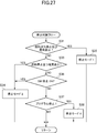
- FIG. It is a flowchart of the water supply in a stop pretreatment.
- 10 is a time chart showing a modified example of stop mode 3.
- It is a block diagram which shows the solid oxide fuel cell system by 2nd Embodiment of this invention.
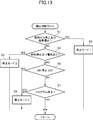
- 7 is a flowchart of stop determination for selecting a stop mode in a solid oxide fuel cell system according to a second embodiment of the present invention.
- FIG. 6 is a time chart schematically showing an example of stop behavior when stop mode 4 is executed in the solid oxide fuel cell system according to the second embodiment of the present invention.
- the control when the stop mode 4 is executed, the temperature and pressure in the fuel cell module, and the state of the tip of the fuel cell unit are time-series.
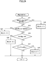
- FIG. 7 is a flowchart of stop determination for selecting a stop mode in a modification of the solid oxide fuel cell system according to the second embodiment of the present invention. It is the time chart which represented an example of the stop behavior of the conventional solid oxide fuel cell system typically in time series.
- FIG. 1 is an overall configuration diagram showing a solid oxide fuel cell system (SOFC) according to a first embodiment of the present invention.
- a solid oxide fuel cell system (SOFC) 1 according to a first embodiment of the present invention includes a fuel cell module 2 and an auxiliary unit 4.
- the fuel cell module 2 includes a housing 6, and a metal case 8 is built in the housing 6 via a heat insulating material 7.
- a fuel cell assembly 12 that performs a power generation reaction with fuel and oxidant gas (air) is disposed in a power generation chamber 10 that is a lower portion of the case 8 that is a sealed space.
- the fuel cell assembly 12 includes ten fuel cell stacks 14 (see FIG. 5), and the fuel cell stack 14 includes 16 fuel cell unit 16 (see FIG. 4). Yes.
- the fuel cell assembly 12 has 160 fuel cell units 16, and all of these fuel cell units 16 are connected in series.
- a combustion chamber 18 that is a combustion section is formed above the above-described power generation chamber 10 of the case 8 of the fuel cell module 2.
- the remaining fuel and the remaining oxidant that have not been used for the power generation reaction. Air
- the case 8 is covered with a heat insulating material 7 to suppress the heat inside the fuel cell module 2 from being diffused to the outside air.
- a reformer 20 for reforming the fuel is disposed above the combustion chamber 18, and the reformer 20 is heated to a temperature at which a reforming reaction can be performed by the combustion heat of the residual gas. Yes.
- an air heat exchanger 22 which is a heat exchanger for heating the power generation air with the remaining combustion gas and preheating the power generation air, is disposed above the reformer 20.
- the auxiliary unit 4 stores pure water tank 26 that stores water condensed from moisture contained in the exhaust from the fuel cell module 2 and makes it pure water with a filter, and water supplied from the water storage tank. Is provided with a water flow rate adjusting unit 28 (such as a “water pump” driven by a motor).
- the auxiliary unit 4 adjusts the flow rate of the fuel gas, the gas shutoff valve 32 for shutting off the fuel supplied from the fuel supply source 30 such as city gas, the desulfurizer 36 for removing sulfur from the fuel gas, A fuel flow adjustment unit 38 (such as a “fuel pump” driven by a motor) and a valve 39 that shuts off fuel gas flowing out from the fuel flow adjustment unit 38 when power is lost.
- the auxiliary unit 4 includes an electromagnetic valve 42 that shuts off air that is an oxidant gas supplied from an air supply source 40, a reforming air flow rate adjusting unit 44 that adjusts the air flow rate, and a power generation air flow rate adjustment A unit 45 (such as an “air blower” driven by a motor), a first heater 46 for heating the reforming air supplied to the reformer 20, and a first heater for heating the power generating air supplied to the power generation chamber 2 heaters 48.
- the first heater 46 and the second heater 48 are provided in order to efficiently raise the temperature at startup, but may be omitted.
- a hot water production apparatus 50 to which exhaust gas is supplied is connected to the fuel cell module 2.
- the hot water production apparatus 50 is supplied with tap water from the water supply source 24, and the tap water is heated by the heat of the exhaust gas and supplied to a hot water storage tank of an external hot water heater (not shown).
- the fuel cell module 2 is provided with a control box 52 for controlling the amount of fuel gas supplied and the like. Furthermore, the fuel cell module 2 is connected to an inverter 54 that is a power extraction unit (power conversion unit) for supplying the power generated by the fuel cell module to the outside.
- FIG. 2 is a side sectional view showing the fuel cell module of the solid oxide fuel cell system (SOFC) according to the first embodiment of the present invention
- FIG. 3 is a sectional view taken along the line III-III in FIG. It is.
- the case 8 in the housing 6 of the fuel cell module 2 has a fuel cell assembly 12, a reformer 20, and an air heat exchanger in order from the bottom as described above. 22 is arranged.
- the reformer 20 is provided with a reformer introduction pipe 62 for introducing pure water, fuel gas to be reformed, and reforming air on the end side surface on the upstream end side.
- the reformer introduction pipe 62 is a circular pipe extending from the side wall surface at one end of the reformer 20, is bent by 90 ° and extends in a substantially vertical direction, and penetrates the upper end surface of the case 8.
- the reformer introduction pipe 62 functions as a water introduction pipe for introducing water into the reformer 20.
- a T-shaped tube 62a is connected to the upper end of the reformer introduction tube 62, and fuel gas and pure water are supplied to both ends of the T-shaped tube 62a extending in a substantially horizontal direction. Pipes for connecting are connected to each other.
- the water supply pipe 63a extends obliquely upward from one side end of the T-shaped pipe 62a.
- the fuel gas supply pipe 63b extends in the horizontal direction from the other side end of the T-shaped pipe 62a, then bends in a U shape, and extends substantially horizontally in the same direction as the water supply pipe 63a.
- an evaporation unit 20a, a mixing unit 20b, and a reforming unit 20c are formed in this order from the upstream side, and the reforming unit 20c is filled with a reforming catalyst.
- the fuel gas and air mixed with the steam (pure water) introduced into the reformer 20 are reformed by the reforming catalyst filled in the reformer 20.
- the reforming catalyst a catalyst obtained by imparting nickel to the alumina sphere surface or a catalyst obtained by imparting ruthenium to the alumina sphere surface is appropriately used.
- a fuel gas supply pipe 64 is connected to the downstream end side of the reformer 20, and the fuel gas supply pipe 64 extends downward and further in an manifold 66 formed below the fuel cell assembly 12. It extends horizontally.
- a plurality of fuel supply holes 64 b are formed in the lower surface of the horizontal portion 64 a of the fuel gas supply pipe 64, and the reformed fuel gas is supplied into the manifold 66 from the fuel supply holes 64 b.
- a pressure fluctuation suppressing flow path resistance portion 64c having a narrow flow path is provided, and the flow path resistance of the fuel gas supply flow path is adjusted. The adjustment of the channel resistance will be described later.
- a lower support plate 68 having a through hole for supporting the fuel cell stack 14 described above is attached above the manifold 66, and the fuel gas in the manifold 66 flows into the fuel cell unit 16. Supplied.
- an air heat exchanger 22 is provided above the reformer 20. Further, as shown in FIG. 2, an ignition device 83 for starting combustion of fuel gas and air is provided in the combustion chamber 18.
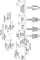
- FIG. 4 is a partial cross-sectional view showing the fuel cell unit of the solid oxide fuel cell system (SOFC) according to the first embodiment of the present invention.
- the fuel cell unit 16 includes a fuel cell 84 and inner electrode terminals 86 that are metal caps connected to both ends of the fuel cell 84.
- the fuel cell 84 is a tubular structure extending in the vertical direction, and includes a cylindrical inner electrode layer 90 that forms a fuel gas flow path 88 therein, a cylindrical outer electrode layer 92, an inner electrode layer 90, and an outer side.
- An electrolyte layer 94 is provided between the electrode layer 92 and the electrode layer 92.
- the inner electrode layer 90 is a fuel electrode through which fuel gas passes and becomes a ( ⁇ ) electrode, while the outer electrode layer 92 is an air electrode in contact with air and becomes a (+) electrode.
- the upper portion 90 a of the inner electrode layer 90 includes an outer peripheral surface 90 b and an upper end surface 90 c exposed to the electrolyte layer 94 and the outer electrode layer 92.
- the inner electrode terminal 86 is connected to the outer peripheral surface 90b of the inner electrode layer 90 through a conductive sealing material 96, and is further in direct contact with the upper end surface 90c of the inner electrode layer 90, thereby Electrically connected.
- a fuel gas channel capillary 98 that communicates with the fuel gas channel 88 of the inner electrode layer 90 is formed.
- the fuel gas passage narrow tube 98 is an elongated thin tube provided so as to extend in the axial direction of the fuel cell 84 from the center of the inner electrode terminal 86. For this reason, a predetermined pressure loss occurs in the flow of the fuel gas flowing from the manifold 66 (FIG. 2) into the fuel gas passage 88 through the fuel gas passage narrow tube 98 of the lower inner electrode terminal 86. . Accordingly, the fuel gas flow passage narrow tube 98 of the lower inner electrode terminal 86 acts as an inflow side flow passage resistance portion, and the flow passage resistance is set to a predetermined value. Further, a predetermined pressure loss also occurs in the flow of the fuel gas flowing out from the fuel gas flow path 88 to the combustion chamber 18 (FIG.
- the fuel gas flow passage narrow tube 98 of the upper inner electrode terminal 86 acts as an outflow side flow passage resistance portion, and the flow passage resistance is set to a predetermined value.
- the inner electrode layer 90 includes, for example, a mixture of Ni and zirconia doped with at least one selected from rare earth elements such as Ca, Y, and Sc, and Ni and ceria doped with at least one selected from rare earth elements.
- the mixture is formed of at least one of Ni and a mixture of lanthanum garade doped with at least one selected from Sr, Mg, Co, Fe, and Cu.
- the electrolyte layer 94 includes, for example, zirconia doped with at least one selected from rare earth elements such as Y and Sc, ceria doped with at least one selected from rare earth elements, lanthanum gallate doped with at least one selected from Sr and Mg, Formed from at least one of the following.
- the outer electrode layer 92 includes, for example, lanthanum manganite doped with at least one selected from Sr and Ca, lanthanum ferrite doped with at least one selected from Sr, Co, Ni and Cu, Sr, Fe, Ni and Cu. It is formed from at least one of lanthanum cobaltite doped with at least one selected from the group consisting of silver and silver.
- FIG. 5 is a perspective view showing a fuel cell stack of the solid oxide fuel cell system (SOFC) according to the first embodiment of the present invention.
- the fuel cell stack 14 includes 16 fuel cell units 16, and these fuel cell units 16 are arranged in two rows of 8 each.
- Each fuel cell unit 16 is supported at its lower end by a rectangular lower support plate 68 (FIG. 2) made of ceramic, and at the upper end, four fuel cell units 16 at both end portions are provided, each having a generally square shape. It is supported by the upper support plate 100.
- the lower support plate 68 and the upper support plate 100 are formed with through holes through which the inner electrode terminal 86 can pass.
- the current collector 102 includes a fuel electrode connection portion 102a that is electrically connected to an inner electrode terminal 86 attached to the inner electrode layer 90 that is a fuel electrode, and an outer peripheral surface of the outer electrode layer 92 that is an air electrode. It is integrally formed so as to connect the air electrode connecting portion 102b that is electrically connected.
- a silver thin film is formed on the entire outer surface of the outer electrode layer 92 (air electrode) of each fuel cell unit 16 as an electrode on the air electrode side. When the air electrode connecting portion 102b contacts the surface of the thin film, the current collector 102 is electrically connected to the entire air electrode.
- two external terminals 104 are respectively connected to the air electrode 86 of the fuel cell unit 16 located at the end of the fuel cell stack 14 (the far left side in FIG. 5). These external terminals 104 are connected to the inner electrode terminal 86 of the fuel cell unit 16 at the end of the adjacent fuel cell stack 14, and as described above, all 160 fuel cell units 16 are connected in series. It has come to be.
- FIG. 6 is a block diagram showing a solid oxide fuel cell system (SOFC) according to the first embodiment of the present invention.
- the solid oxide fuel cell system 1 includes a control unit 110.
- the control unit 110 includes operation buttons such as “ON” and “OFF” for operation by the user.
- the operation device 112, a display device 114 for displaying various data such as a power generation output value (wattage), and a notification device 116 for issuing a warning (warning) in an abnormal state are connected.
- control unit 110 incorporates a microprocessor, a memory, and a program (not shown) for operating these components, and thereby, based on input signals from the respective sensors, the auxiliary unit 4, The inverter 54 and the like are controlled.
- the notification device 116 may be connected to a remote management center and notify the management center of an abnormal state.
- the combustible gas detection sensor 120 is for detecting a gas leak, and is attached to the fuel cell module 2 and the auxiliary unit 4.
- the CO detection sensor 122 detects whether or not CO in the exhaust gas originally discharged to the outside through the exhaust gas passage 80 or the like leaks to an external housing (not shown) that covers the fuel cell module 2 and the auxiliary unit 4. Is to do.
- the hot water storage state detection sensor 124 is for detecting the temperature and amount of hot water in a water heater (not shown).
- the power state detection sensor 126 is for detecting the current and voltage of the inverter 54 and the distribution board (not shown).
- the power generation air flow rate detection sensor 128 is for detecting the flow rate of power generation air supplied to the power generation chamber 10.
- the reforming air flow sensor 130 is for detecting the flow rate of the reforming air supplied to the reformer 20.
- the fuel flow sensor 132 is for detecting the flow rate of the fuel gas supplied to the reformer 20.
- the water flow rate sensor 134 is for detecting the flow rate of pure water supplied to the reformer 20.
- the water level sensor 136 is for detecting the water level of the pure water tank 26.
- the pressure sensor 138 is for detecting the pressure on the upstream side outside the reformer 20.
- the exhaust temperature sensor 140 is for detecting the temperature of the exhaust gas flowing into the hot water production apparatus 50.
- the power generation chamber temperature sensor 142 is provided on the front side and the back side in the vicinity of the fuel cell assembly 12, and detects the temperature in the vicinity of the fuel cell stack 14 to thereby detect the fuel cell stack. 14 (ie, the fuel cell 84 itself) is estimated.
- the combustion chamber temperature sensor 144 is for detecting the temperature of the combustion chamber 18.
- the exhaust gas chamber temperature sensor 146 is for detecting the temperature of the exhaust gas in the exhaust gas chamber 78.
- the reformer temperature sensor 148 is for detecting the temperature of the reformer 20, and calculates the temperature of the reformer 20 from the inlet temperature and the outlet temperature of the reformer 20.
- the outside air temperature sensor 150 is for detecting the temperature of the outside air when the solid oxide fuel cell system (SOFC) is disposed outdoors. Further, a sensor for measuring the humidity or the like of the outside air may be provided.
- SOFC solid oxide fuel cell system
- Signals from these sensors are sent to the control unit 110, and the control unit 110, based on data based on these signals, the water flow rate adjustment unit 28, the fuel flow rate adjustment unit 38, the reforming air flow rate adjustment unit 44, A control signal is sent to the power generation air flow rate adjusting unit 45 to control each flow rate in these units.
- FIG. 7 is a perspective view of the reformer 20
- FIG. 8 is a perspective view showing the inside of the reformer 20 with the top plate removed.
- FIG. 9 is a plan sectional view showing the flow of fuel inside the reformer 20.
- the reformer 20 is a rectangular parallelepiped metal box and is filled with a reforming catalyst for reforming fuel.
- a reformer introduction pipe 62 for introducing water, fuel, and reforming air is connected to the upstream side of the reformer 20.
- a fuel gas supply pipe 64 for discharging the internally reformed fuel is connected to the downstream side of the reformer 20.
- an evaporation unit 20a that is an evaporation chamber is provided on the upstream side, and a mixing unit 20b is provided on the downstream side adjacent to the evaporation unit 20a. ing. Further, a reforming section 20c is provided on the downstream side adjacent to the mixing section 20b. Inside the evaporation part 20a, a plurality of partition plates are arranged to form a meandering and meandering passage. The water introduced into the reformer 20 is evaporated in the evaporation unit 20a in a state where the temperature is increased, and becomes water vapor.
- the mixing part 20b is comprised from the chamber which has a predetermined
- the fuel gas and the reforming air introduced into the reformer 20 are mixed with the water vapor generated in the evaporation unit 20a while passing through the winding path of the mixing unit 20b.
- a meandering passage is formed in the reforming section 20c by arranging a plurality of partition plates, and the passage is filled with a catalyst.
- a mixture of fuel gas, water vapor and reforming air is introduced through the evaporation unit 20a and the mixing unit 20b, a partial oxidation reforming reaction and a steam reforming reaction occur in the reforming unit 20c.
- a mixture of fuel gas and steam is introduced, only the steam reforming reaction occurs in the reforming unit 20c.
- the evaporation unit, the mixing unit, and the reforming unit are integrally configured to form one reformer.
- a reformer including only the reforming unit is used. It is also possible to provide a mixing section and an evaporation chamber adjacent to the upstream side.
- the fuel gas, water, and reforming air introduced into the evaporator 20a of the reformer 20 meander in the transverse direction of the reformer 20, and are introduced during this period.
- the evaporated water evaporates to become water vapor.
- An evaporation / mixing unit partition 20d is provided between the evaporation unit 20a and the mixing unit 20b, and a partition opening 20e is provided in the evaporation / mixing unit partition 20d.
- This partition opening 20e is a rectangular opening provided in an upper half of the half of one side of the evaporation / mixing section partition 20d.
- a mixing / reforming section partition wall 20f is provided between the mixing section 20b and the reforming section 20c, and a narrow flow path is formed by providing a large number of communication holes 20g in the mixing / reforming section partition wall 20f. Has been. The fuel gas or the like mixed in the mixing unit 20b flows into the reforming unit 20c through these communication holes 20g.
- the fuel or the like that has flowed into the reforming unit 20c flows in the longitudinal direction in the center of the reforming unit 20c, and then splits into two to be folded back, and the two passages are folded back again toward the downstream end of the reforming unit 20c. Therefore, they are merged and flow into the fuel gas supply pipe 64.
- the fuel is reformed by the catalyst filled in the passage while passing through the meandering passage.
- bumping may occur in which a certain amount of water rapidly evaporates in a short time, and the internal pressure may increase.
- the mixing unit 20b has a chamber with a predetermined volume and the mixing / reforming unit partition wall 20f has a narrow flow path
- the reforming unit 20c has a sudden pressure fluctuation in the evaporation unit 20a. The influence of is difficult to reach. Therefore, the chamber of the mixing unit 20b and the narrow channel of the mixing / reforming unit partition 20f function as pressure fluctuation absorbing means.
- FIG. 10 is a perspective view showing the metal case 8 and the air heat exchanger 22 housed in the housing 6.
- FIG. 11 is a cross-sectional view showing the positional relationship between the evaporation chamber heat insulating material and the evaporation section.
- the air heat exchanger 22 is a heat exchanger disposed above the case 8 in the fuel cell module 2. Further, as shown in FIGS. 2 and 3, a combustion chamber 18 is formed inside the case 8, and a plurality of fuel cell units 16, a reformer 20 and the like are accommodated therein. 22 is located above these.
- the air heat exchanger 22 collects and uses the heat of the combustion gas that is combusted in the combustion chamber 18 and discharged as exhaust gas so as to preheat the power generation air introduced into the fuel cell module 2. It is configured. Further, as shown in FIG.
- an evaporation chamber heat insulating material 23 which is an internal heat insulating material, is disposed between the upper surface of the case 8 and the bottom surface of the air heat exchanger 22 so as to be sandwiched between them.
- the evaporation chamber heat insulating material 23 is disposed between the reformer 20 and the air heat exchanger 22.
- a heat insulating material 7 as an outer heat insulating material (FIG. 2).
- the air heat exchanger 22 includes a plurality of combustion gas pipes 70 and a power generation air flow path 72.
- an exhaust gas collecting chamber 78 is provided at one end of the plurality of combustion gas pipes 70, and the exhaust gas collecting chamber 78 is communicated with each combustion gas pipe 70.
- an exhaust gas discharge pipe 82 is connected to the exhaust gas collecting chamber 78.
- the other end of each combustion gas pipe 70 is open, and this open end communicates with the combustion chamber 18 in the case 8 via a communication opening 8 a formed on the upper surface of the case 8. Has been.
- the combustion gas piping 70 is a plurality of metal circular tubes oriented in the horizontal direction, and each circular tube is arranged in parallel.
- the power generation air flow path 72 is constituted by a space outside each combustion gas pipe 70.
- a power generation air introduction pipe 74 (FIG. 10) is connected to the end of the power generation air flow path 72 on the exhaust gas discharge pipe 82 side so that the air outside the fuel cell module 2 is used for power generation.
- the air is introduced into the power generation air flow path 72 through the air introduction pipe 74.
- the power generation air introduction pipe 74 protrudes in the horizontal direction from the air heat exchanger 22 in parallel with the exhaust gas discharge pipe 82.
- a pair of communication flow paths 76 are connected to both side surfaces of the other end of the power generation air flow path 72, and the power generation air flow path 72 and each communication flow path 76 are connected. Are communicated with each other via an exit port 76a.
- power generation air supply passages 77 are provided on both side surfaces of the case 8.
- Each communication channel 76 provided on both side surfaces of the air heat exchanger 22 communicates with an upper portion of a power generation air supply channel 77 provided on both side surfaces of the case 8.
- a large number of air outlets 77 a are arranged in the horizontal direction at the lower portion of each power generation air supply passage 77. The power generation air supplied through each power generation air supply path 77 is injected toward the lower side surface of the fuel cell stack 14 in the fuel cell module 2 from a large number of air outlets 77a.
- a rectifying plate 21 that is a partition wall is attached to the ceiling surface inside the case 8, and the rectifying plate 21 has an opening 21 a.
- the rectifying plate 21 is a plate member disposed horizontally between the ceiling surface of the case 8 and the reformer 20.
- the rectifying plate 21 is configured to adjust the flow of the gas flowing upward from the combustion chamber 18 and to guide it to the inlet of the air heat exchanger 22 (communication opening 8a in FIG. 2).
- the power generation air and the combustion gas traveling upward from the combustion chamber 18 flow into the upper side of the rectifying plate 21 through the opening 21 a provided in the center of the rectifying plate 21, and the upper surface of the rectifying plate 21 and the ceiling surface of the case 8. 2 flows to the left in FIG.
- the opening 21a is provided above the reforming unit 20c of the reformer 20, and the gas rising through the opening 21a is on the side opposite to the evaporation unit 20a. , Flows to the left exhaust passage 21b in FIGS. For this reason, the space above the evaporation unit 20a (the right side in FIGS. 2 and 11) acts as a gas retention space 21c in which the flow of exhaust gas is slower than the space above the reforming unit 20c and the flow of exhaust gas is stagnant.
- a vertical wall 21d is provided at the edge of the opening 21a of the rectifying plate 21 over the entire circumference, and the vertical wall 21d allows the exhaust above the rectifying plate 21 from the space below the rectifying plate 21.
- the flow path flowing into the passage 21b is narrowed.
- a falling wall 8b (FIG. 2) is provided over the entire circumference at the edge of the communication opening 8a that allows the exhaust passage 21b and the air heat exchanger 22 to communicate with each other.
- the flow path flowing into the air heat exchanger 22 is narrowed.
- the heat insulating material 23 for the evaporation chamber is a heat insulating material attached to the bottom surface of the air heat exchanger 22 so as to substantially cover the whole. Therefore, the heat insulating material 23 for evaporation chamber is arrange
- the evaporating chamber heat insulating material 23 is formed so that the high-temperature gas in the exhaust passage 21 b and the gas retention space 21 c formed between the upper surface of the rectifying plate 21 and the ceiling surface of the case 8 flows on the bottom surface of the air heat exchanger 22. It arrange
- the heat directly transferred to the bottom surface of the air heat exchanger 22 from the exhaust gas remaining in the exhaust passage above the evaporation unit 20a is reduced, and the surroundings of the evaporation unit 20a are reduced.
- the temperature tends to rise.
- the evaporation chamber heat insulating material 23 is disposed, so that heat dissipation from the reformer 20 is suppressed, that is, the heat around the evaporation unit 20a is used for air.
- the heat exchanger 22 is less likely to be deprived, and the temperature drop of the evaporation unit 20a is moderated.
- the heat insulating material 23 for the evaporation chamber includes a heat insulating material 7 that is an outer heat insulating material covering the case 8 of the fuel cell module 2 and the entire air heat exchanger 22 in order to suppress the dissipation of heat to the outside air. Apart from this, it is a heat insulating material arranged inside the heat insulating material 7.
- the heat insulating material 7 is configured to have higher heat insulating properties than the heat insulating material 23 for the evaporation chamber. That is, the thermal resistance between the inner surface and the outer surface of the heat insulating material 7 is larger than the thermal resistance between the upper surface and the lower surface of the evaporation chamber heat insulating material 23. That is, when the heat insulating material 7 and the evaporation chamber heat insulating material 23 are made of the same material, the heat insulating material 7 is made thicker than the evaporation chamber heat insulating material 23.
- the fuel is introduced into the evaporation section 20a of the reformer 20 through the fuel gas supply pipe 63b, the T-shaped pipe 62a, and the reformer introduction pipe 62, and the pure water is supplied to the water supply pipe 63a, It is introduced into the evaporator 20a through the T-shaped tube 62a and the reformer introducing tube 62. Accordingly, the supplied fuel and water are merged in the T-shaped tube 62 a and introduced into the evaporation unit 20 a through the reformer introduction tube 62.
- the pure water introduced into the evaporation unit 20a is evaporated relatively quickly to become water vapor.
- the evaporated water vapor and fuel are mixed in the mixing unit 20 b and flow into the reforming unit 20 c of the reformer 20.
- the fuel introduced into the reforming unit 20c together with the steam is steam reformed here and reformed into a fuel gas rich in hydrogen.
- the fuel reformed in the reforming unit 20c goes down through the fuel gas supply pipe 64 and flows into the manifold 66 which is a dispersion chamber.
- the manifold 66 is a rectangular parallelepiped space having a relatively large volume, which is disposed on the lower side of the fuel cell stack 14, and a plurality of holes provided on the upper surface thereof constitute each fuel cell constituting the fuel cell stack 14. It communicates with the inside of the unit 16.
- the fuel introduced into the manifold 66 flows out from the upper end of the fuel cell unit 16 through the many holes provided on the upper surface thereof, through the fuel electrode side of the fuel cell unit 16, that is, through the inside of the fuel cell unit 16. .
- hydrogen gas as a fuel passes through the inside of the fuel cell unit 16, it reacts with oxygen in the air passing outside the fuel cell unit 16 as an air electrode (oxidant gas electrode) to generate a charge. Is done.
- the remaining fuel that is not used for power generation flows out from the upper end of each fuel cell unit 16 and is combusted in a combustion chamber 18 provided above the fuel cell stack 14.
- the power generation air that is the oxidant gas is sent into the fuel cell module 2 via the power generation air introduction pipe 74 by the power generation air flow rate adjustment unit 45 that is a power generation oxidant gas supply device.
- the air sent into the fuel cell module 2 is introduced into the power generation air passage 72 of the air heat exchanger 22 via the power generation air introduction pipe 74 and preheated.
- the preheated air flows out to each communication channel 76 via each outlet port 76a (FIG. 3).
- the power generation air flowing into each communication channel 76 flows downward through the power generation air supply passages 77 provided on both side surfaces of the fuel cell module 2, and the fuel cell stack 14 from a number of outlets 77a.
- the air injected into the power generation chamber 10 comes into contact with the outer surface of each fuel cell unit 16 on the air electrode side (oxidant gas electrode side) of the fuel cell stack 14, and a part of oxygen in the air is in contact with it. Used for power generation. Moreover, the air injected to the lower part of the power generation chamber 10 through the blower outlet 77a rises in the power generation chamber 10 while being used for power generation. The air rising in the power generation chamber 10 burns the fuel flowing out from the upper end of each fuel cell unit 16. The combustion heat generated by this combustion heats the evaporation section 20a, the mixing section 20b, and the reforming section 20c of the reformer 20 disposed above the fuel cell stack 14.
- the combustion gas generated by burning the fuel heats the upper reformer 20 and then flows into the upper side of the rectifying plate 21 through the opening 21 a above the reformer 20.
- the combustion gas that has flowed into the upper side of the rectifying plate 21 is guided to the communication opening 8 a that is the inlet of the air heat exchanger 22 through the exhaust passage 21 b formed by the rectifying plate 21.
- the combustion gas that has flowed into the air heat exchanger 22 from the communication opening 8 a flows into the open end of each combustion gas pipe 70 and flows through the power generation air flow path 72 outside each combustion gas pipe 70. Are exchanged with each other and collected in an exhaust gas collecting chamber 78.
- the exhaust gas collected in the exhaust gas collection chamber 78 is discharged to the outside of the fuel cell module 2 through the exhaust gas discharge pipe 82.
- the evaporation of water in the evaporation unit 20a and the steam reforming reaction, which is an endothermic reaction in the reforming unit 20c, are promoted, and the power generation air in the air heat exchanger 22 is preheated.
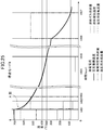
- FIG. 12 is a time chart showing an example of each supply amount of fuel and the like and the temperature of each part in the startup process.
- shaft of FIG. 12 has shown temperature, and each supply amount of fuel etc. has shown those increase / decrease roughly.
- the temperature of the fuel cell stack 14 at room temperature is raised to a temperature at which power generation is possible.
- the supply of power generation air and reforming air is started.
- the control unit 110 that is a controller sends a signal to the power generation air flow rate adjustment unit 45 that is a power generation oxidant gas supply device to operate it.
- the power generation air is introduced into the fuel cell module 2 through the power generation air introduction pipe 74 and flows into the power generation chamber 10 through the air heat exchanger 22 and the power generation air supply path 77.
- the control unit 110 sends a signal to the reforming air flow rate adjustment unit 44 which is a reforming oxidant gas supply device to operate it.
- the reforming air introduced into the fuel cell module 2 flows into the interior of each fuel cell unit 16 through the reformer 20 and the manifold 66, and flows out from the upper end thereof. Note that at time t0, no reforming reaction occurs in the reformer 20 because fuel has not yet been supplied.
- the supply amount of power generation air started at time t0 in FIG. 12 is about 100 L / min, and the supply amount of reforming air is about 10.0 L / min.
- fuel supply is started at time t1 after a predetermined time from time t0 in FIG.
- the control unit 110 sends a signal to the fuel flow rate adjustment unit 38 which is a fuel supply device to operate it.
- the fuel supply amount started at time t1 is about 5.0 L / min.
- the fuel introduced into the fuel cell module 2 flows into the interior of each fuel cell unit 16 through the reformer 20 and the manifold 66, and flows out from the upper end thereof.
- the reformer reaction is not generated in the reformer 20 because the temperature of the reformer is still low.
- an ignition process for the supplied fuel is started.
- the control unit 110 sends a signal to an ignition device 83 (FIG. 2) that is an ignition means, and ignites the fuel flowing out from the upper end of each fuel cell unit 16.
- the ignition device 83 repeatedly generates a spark in the vicinity of the upper end of the fuel cell stack 14 and ignites the fuel flowing out from the upper end of each fuel cell unit 16.
- the control unit 110 sends a signal to the water flow rate adjustment unit 28 (FIG. 6), which is a water supply device, to activate it.
- the supply amount of water started at time t3 is 2.0 cc / min.
- the fuel supply amount is maintained at about 5.0 L / min.
- the supply amounts of the power generation air and the reforming air are also maintained at the previous values.
- the ratio O 2 / C of oxygen O 2 in the reforming air and carbon C in the fuel becomes about 0.32.
- the supplied fuel flows out from the upper end of each fuel cell unit 16 as off-gas and is burned here.
- This combustion heat heats the reformer 20 disposed above the fuel cell stack 14.
- an evaporating chamber heat insulator 23 is disposed above the reformer 20 (above the case 8), so that immediately after the start of fuel combustion, the temperature of the reformer 20 suddenly increases from room temperature. To rise. Since the outside air is introduced into the air heat exchanger 22 disposed on the heat insulating material 23 for the evaporation chamber, the air heat exchanger 22 has a low temperature, particularly immediately after the start of combustion, and serves as a cooling source. Cheap.
- the evaporation chamber heat insulating material 23 is disposed between the upper surface of the case 8 and the bottom surface of the air heat exchanger 22, so that the reformer 20 disposed in the upper portion of the case 8 The movement of heat to the air heat exchanger 22 is suppressed, and heat is easily trapped in the vicinity of the reformer 20 in the case 8.
- the space above the rectifying plate 21 above the evaporation unit 20a is configured as a gas retention space 21c (FIG. 2) in which the flow of combustion gas is slow, so that the vicinity of the evaporation unit 20a is double insulated. And the temperature rises more rapidly.
- the evaporation chamber heat insulating material 23 that insulates between the reformer 20 and the air heat exchanger 22 is a heat insulating material provided inside the heat insulating material 7. Therefore, the heat insulating material 23 for the evaporation chamber does not suppress the dissipation of heat from the fuel cell module 2, but immediately increases the temperature of the reformer 20, particularly the evaporation section 20a immediately after the start of off-gas combustion.
- the supply of the reforming water is started from time t3 immediately after the ignition is confirmed, and the temperature of the evaporation unit 20a is rapidly increased.
- time t4 water vapor has already been generated in the evaporator 20a and supplied to the reformer 20b. That is, after the off-gas is ignited, the supply of water is started a predetermined time before the temperature of the reforming unit 20b reaches the temperature at which the partial oxidation reforming reaction occurs, and reaches the temperature at which the partial oxidation reforming reaction occurs. At that time, a predetermined amount of water is stored in the evaporation unit 20a, and water vapor is generated.
- the reforming reaction that occurs in the reforming unit 20b after time t4 is an autothermal reforming reaction (ATR) shown in Formula (3) in which the partial oxidation reforming reaction and the steam reforming reaction are mixed. That is, the ATR1 process is started at time t4.
- ATR autothermal reforming reaction
- the reformer temperature at time t4 is about 200.degree.
- the reformer temperature is lower than the temperature at which the partial oxidation reforming reaction occurs, but the temperature detected by the reformer temperature sensor 148 (FIG. 6) is the average temperature of the reforming unit 20b.
- the reforming unit 20b partially reaches the temperature at which the partial oxidation reforming reaction occurs, and the steam reforming reaction is performed by the reaction heat of the generated partial oxidation reforming reaction. Is also triggered.
- the supply of water is started before the reforming unit 20b reaches the temperature at which the partial oxidation reforming occurs, and the partial oxidation reforming reaction is performed independently. Will not occur.
- the process shifts from the ATR1 process to the ATR2 process at time t5 in FIG.
- the water supply amount is changed from 2.0 cc / min to 3.0 cc / min.
- the fuel supply amount, the reforming air supply amount, and the power generation air supply amount are maintained at the previous values.
- the steam / carbon ratio S / C in the ATR2 step is increased to 0.64, while the reforming air / carbon ratio O 2 / C is maintained at 0.32.
- the ratio S / C of steam and carbon is increased, so that the amount of carbon that can be partially oxidized and reformed is not reduced.
- the amount of carbon that can be steam reformed is increased. This makes it possible to increase the amount of carbon subjected to steam reforming as the temperature of the reforming unit 20b increases while reliably avoiding the risk of carbon deposition in the reforming unit 20b.
- the process proceeds from the ATR2 process to the ATR3 process. Accordingly, the fuel supply amount is changed from 5.0 L / min to 4.0 L / min, and the reforming air supply amount is changed from 9.0 L / min to 6.5 L / min. Also, the previous values are maintained for the water supply amount and the power generation air supply amount. This increases the steam / carbon ratio S / C in the ATR3 step to 0.80, while the reforming air to carbon ratio O 2 / C is reduced to 0.29.
- the process proceeds to the SR2 step. Accordingly, the fuel supply amount is changed from 3.0 L / min to 2.5 L / min, and the water supply amount is changed from 7.0 cc / min to 6.0 cc / min. In addition, the previous value of the power supply air supply amount is maintained. Thereby, in the SR2 step, the ratio S / C of water vapor to carbon is set to 2.56.
- the process proceeds to the power generation process.
- power is extracted from the fuel cell stack 14 to the inverter 54 (FIG. 6), and power generation is started.
- the reforming unit 20b reforms the fuel exclusively by steam reforming. Further, in the power generation process, the fuel supply amount, the power generation air supply amount, and the water supply amount are changed corresponding to the output power required for the fuel cell module 2.
- FIG. 28 is a time chart schematically showing an example of the stop behavior of a conventional solid oxide fuel cell system in time series.
- the shutdown operation of the fuel cell that has been generating is operated.
- the fuel supply amount, the water supply amount for reforming, and the air supply amount for power generation are reduced to zero and removed from the fuel cell module in a short time.
- the generated current (generated current) is also made zero. That is, the supply of fuel, water, and power generation air to the fuel cell module is stopped in a short time, and the extraction of electric power from the fuel cell module is stopped. Further, even when the supply of fuel and electricity to the solid oxide fuel cell system is lost due to a disaster or the like, the stop behavior becomes the same state as in FIG.
- the graph of each supply amount in FIG. 28, an electric current, and a voltage shows a change tendency, and does not represent a specific value.
- the voltage value generated in the fuel cell stack rises (however, the current is zero). Further, at time t501, the air supply amount for power generation is set to zero, so that air is not forcibly sent into the fuel cell module. After time t501, the fuel cell stack is kept for a long time. Naturally cooled.
- the present inventor has found that there is a risk that the fuel electrode may be oxidized due to the backflow of air to the fuel electrode side even if such a conventional fuel cell is shut down.
- the reverse flow of air from the air electrode side to the fuel electrode side is generated based on the pressure difference between the inside (fuel electrode side) and the outside (air electrode side) of the fuel cell unit.
- the reformed fuel is pumped to the fuel electrode side of the fuel cell unit.
- power generation air is also sent to the air electrode side of the fuel cell unit.
- the pressure on the fuel electrode side of the fuel cell unit is higher than the pressure on the air electrode side, and fuel is ejected from the fuel electrode side of the fuel cell unit to the air electrode side.
- the fuel is ejected from the fuel electrode side where the pressure is high to the air electrode side where the pressure is low.
- the pressure on the air electrode side in the fuel cell module is also higher than the outside air pressure (atmospheric pressure)
- the air on the air electrode side in the fuel cell module (and from the fuel electrode side) after shutdown is stopped.
- the ejected fuel gas is discharged to the outside of the fuel cell module through the exhaust passage. For this reason, after the shutdown is stopped, the pressure decreases on the fuel electrode side and the air electrode side of the fuel cell unit, and finally converges to atmospheric pressure.
- the behavior in which the pressure decreases on the fuel electrode side and the air electrode side is the flow resistance between the fuel electrode side and the air electrode side of the fuel cell unit, and between the air electrode side and the outside air in the fuel cell module. It will be affected by channel resistance. When the pressures on the fuel electrode side and the air electrode side are equal, the air on the air electrode side enters the fuel electrode side due to diffusion.
- the behavior of pressure after shutdown is also affected by temperature changes on the fuel electrode side and the air electrode side.
- the temperature on the fuel electrode side of the fuel cell unit is drastically lower than that on the air electrode side, the volume of fuel gas in the fuel cell unit shrinks, so the pressure on the fuel electrode side decreases and air Backflow occurs.
- the pressure on the fuel electrode side and air electrode side after shutdown is affected by the flow resistance of each part in the fuel cell module, the temperature distribution in the fuel cell module, the amount of accumulated heat, etc. It changes complicatedly.
- output current 0
- the output voltage of the cell stack rapidly increases (A part in FIG. 28). This is because immediately after the shutdown is stopped, a lot of hydrogen is present on the fuel electrode side, air is present on the air electrode side, and the current extracted from the cell stack is set to zero.
- the output voltage of the cell stack rapidly decreases (part B in FIG. 28). This is because the hydrogen existing on the fuel electrode side of each fuel cell unit flows out after the shutdown is stopped and the fuel electrode side. It is estimated that this is because the concentration of hydrogen decreases and the concentration of air on the air electrode side decreases due to the outflowing hydrogen.
- the output voltage of the cell stack decreases with time, and when the temperature in the fuel cell module decreases below the oxidation lower limit temperature (C portion in FIG. 28), the output voltage greatly decreases.
- the fuel electrode is exposed to the risk of oxidation.
- a phenomenon occurs in which the pressure on the fuel electrode side becomes lower than the pressure on the air electrode side before the temperature in the fuel cell module falls below the lower oxidation limit temperature.
- the fuel cell unit has an adverse effect.
- a phenomenon occurs in which the temperature inside the fuel cell module rises after the shutdown stop despite the fuel supply being stopped ( Not shown).
- the temperature in the fuel cell module may rise more than the time of power generation operation for about an hour after the shutdown is stopped.
- Such a temperature rise is caused by a steam reforming reaction, which is an endothermic reaction occurring in the reformer during the power generation operation, due to the stop of the fuel supply. It is considered that the fuel remaining in the manifold that distributes the fuel continuously burns in the combustion chamber even after the fuel supply is stopped.
- the pressure on the fuel electrode side of each fuel cell unit may be lower than the pressure on the air electrode side. In such a case, there is a high possibility that the air on the air electrode side outside the fuel cell unit will flow backward to the internal fuel electrode side and the fuel cell unit will be damaged.
- the flow path resistance of each part in the fuel cell module is set to an appropriate value, and the shutdown stop circuit 110a ( The risk of oxidation of the fuel electrode is greatly suppressed by the control in FIG.
- FIG. 13 is a flowchart of stop determination for selecting a stop mode in the solid oxide fuel cell system 1 according to the first embodiment of the present invention.
- the flowchart in FIG. 13 is a flowchart for determining which stop mode to select based on a predetermined condition, and is repeatedly executed at predetermined time intervals during operation of the solid oxide fuel cell system 1. Is done.
- step S1 of FIG. 13 it is determined whether or not the supply of fuel gas from the fuel supply source 30 (FIG. 1) and the supply of electric power from the commercial power source are stopped.
- the process proceeds to step S2, and in step S2, stop mode 1 which is an emergency stop mode is selected, and one process of the flowchart of FIG. 13 is performed. finish.
- stop mode 1 As the case where the stop mode 1 is selected, it is assumed that the supply of fuel gas and electric power is stopped due to a natural disaster or the like, and it is considered that the frequency of such stop is extremely low.
- step S3 whether or not the supply of the fuel gas is stopped and the electric power is supplied is determined. To be judged. If the supply of fuel gas is stopped and power is supplied, the process proceeds to step S4, and otherwise, the process proceeds to step S5.
- step S4 stop mode 2 which is one of the normal stop modes is selected, and one process of the flowchart of FIG. 13 is completed. As the case where the stop mode 2 is selected, it is assumed that the supply of the fuel gas is temporarily stopped due to the construction of the fuel gas supply path or the like, and it is considered that such a stop is rarely performed. .
- step S5 it is determined whether or not the stop switch has been operated by the user. If the stop switch is operated by the user, the process proceeds to step S6, and if not, the process proceeds to step S7.
- step S6 stop mode 3 is selected as one of the switch stop modes in the normal stop mode, and one process of the flowchart of FIG. 13 ends.
- the stop mode 3 since the user of the solid oxide fuel cell system 1 is absent for a long period of time, the operation of the solid oxide fuel cell system 1 is intentionally performed for a relatively long period of time. It is assumed that the frequency of stopping is not so high.
- step S7 it is determined whether or not it is a periodic stop periodically executed at a predetermined time. If it is a regular stop, the process proceeds to step S6. If it is not a regular stop, the one-time process in the flowchart of FIG. 13 is terminated. In step S6, the stop mode 3 is selected as the program stop mode in the normal stop mode in the same manner as the switch stop mode, and one process in the flowchart of FIG. 13 ends. As the case where the program stop mode is executed, it is assumed that the microcomputer meter provided in the fuel supply source 30 is supported.
- the fuel supply source 30 is provided with a microcomputer meter (not shown), and the microcomputer meter is in a state where the supply of fuel gas is completely stopped for about one month.
- the microcomputer meter is in a state where the supply of fuel gas is completely stopped for about one month.
- the solid oxide fuel cell system 1 needs to be stopped for about one hour or more once a month. Therefore, it is assumed that the stop in the program stop mode is performed at a frequency of about once or more per month, and is the most frequently performed stop.
- the solid oxide fuel cell system 1 can continue the power generation by operating the auxiliary unit 4 with the electric power generated by the fuel cell stack 14.
- the present invention can also be configured so that power generation is stopped when the supply of power continues for a predetermined long time.
- FIG. 14 schematically shows an example of stop behavior when the stop mode 1 (step S2 in FIG. 13) is executed in the solid oxide fuel cell system 1 according to the first embodiment of the present invention. It is a time chart.
- FIG. 15 is a diagram for explaining the control, the temperature and pressure in the fuel cell module, and the state of the tip of the fuel cell unit in time series when the stop mode 1 is executed.
- the air (and the fuel ejected from the fuel electrode side) present on the air electrode side of each fuel cell unit 16 is the pressure on the air electrode side (pressure in the power generation chamber 10 (FIG. 1)) and the atmospheric pressure. Is discharged to the outside of the fuel cell module 2 through the exhaust passage 21b, the air heat exchanger 22 and the like. Accordingly, after the shutdown is stopped, the pressure on the fuel electrode side and the air electrode side of each fuel cell unit 16 naturally decreases.
- a fuel gas flow passage narrow tube 98 which is an outflow side flow passage resistance portion is provided at the upper end portion of each fuel cell unit 16, and the vertical wall 21d and the falling wall 8b (FIG. 2) are provided in the exhaust passage 21b. ) Is provided.
- the flow resistance of the fuel gas flow narrow tube 98 is set so that the pressure drop on the fuel electrode side after the fuel supply and power generation is stopped is more gradual than the pressure drop on the air electrode side.
- the solid oxide fuel cell system 1 of the present embodiment appropriately tunes the flow resistance in each part of the fuel and exhaust passages, so that the fuel cell unit 16 can be placed on the fuel electrode side even after shutdown.
- the fuel is configured to remain for a long time.
- the pressure on the air electrode side rapidly decreases after the shutdown is stopped.
- the pressure difference between the fuel electrode side and the air electrode side increases, and on the contrary, the outflow of fuel from the fuel electrode side is promoted.
- the pressure drop on the air electrode side is moderate compared to the pressure drop on the fuel electrode side.
- the exhaust gas passage is tuned as described above. For this reason, even when left undisturbed after shutdown, the pressure on the fuel electrode side decreases while maintaining a pressure higher than the pressure on the air electrode side until the temperature of the fuel electrode decreases to the oxidation suppression temperature. The pressure higher than the atmospheric pressure is maintained, and the risk that the fuel electrode is oxidized can be sufficiently suppressed. As shown in FIG.
- the output voltage of the fuel cell stack 14 shown by the thick broken line once greatly increases.
- the drop is less than that of the conventional solid oxide fuel cell system (FIG. 28), and a relatively high voltage continues for a long time.
- a relatively high voltage is maintained until time t ⁇ b> 102 when the temperature on the fuel electrode side and the air electrode side decreases to a predetermined oxidation suppression temperature after shutdown. This indicates that the fuel remains on the fuel electrode side of each fuel cell unit 16 until time t102 when the temperature drops to the oxidation suppression temperature.
- the oxidation suppression temperature means a temperature at which the risk that the fuel electrode is oxidized is sufficiently reduced.
- the risk of the anode being oxidized gradually decreases with decreasing temperature and eventually becomes zero. For this reason, even if the oxidation suppression temperature is in a temperature range slightly higher than the oxidation lower limit temperature, which is the lowest temperature at which oxidation of the fuel electrode can occur, the risk of fuel electrode oxidation can be sufficiently reduced.
- such an oxidation suppression temperature is considered to be about 350 ° C. to 400 ° C.
- an oxidation lower limit temperature is considered to be about 250 ° C. to 300 ° C.
- the fuel / exhaust gas passage is disposed in the air electrode in the fuel cell module 2 until the temperature of the fuel electrode decreases to the oxidation suppression temperature after the shutdown is stopped.
- the pressure on the fuel electrode side is maintained higher than the atmospheric pressure, and the pressure on the fuel electrode side is maintained higher than the pressure on the air electrode side. Therefore, the fuel / exhaust gas passage functions as a mechanical pressure holding means for extending the time until the pressure on the fuel electrode side approaches the pressure on the air electrode side.
- FIG. 15 is a diagram for explaining the operation in the stop mode 1, in which the upper stage shows a graph schematically showing the pressure change on the fuel electrode side and the air electrode side, and the middle stage shows the control operation by the control unit 110 and the fuel cell module.
- the temperature in 2 is shown in time series, and the lower part shows the state of the upper end portion of the fuel cell unit 16 at each time point.
- the temperature in the fuel cell module 2 is about 700 ° C.
- the fuel gas remaining without being used for power generation is ejected from the fuel gas channel narrow tube 98 at the upper end of the fuel cell unit 16.
- the gas is combusted at the upper end of the fuel gas passage narrow tube 98.
- the flow rate of the ejected fuel gas decreases, and as shown in the lower part (2) of FIG.
- the flame at the tip of the gas flow path narrow tube 98 disappears.
- the fuel gas channel narrow tube 98 is formed in an elongated shape, when the flame is drawn into the fuel gas channel narrow tube 98 due to a decrease in the fuel gas flow rate, the flame disappears quickly. By quickly extinguishing the flame, consumption of the fuel gas remaining inside the fuel cell unit 16 and the like is suppressed, and the time during which the remaining fuel can be maintained on the fuel electrode side is extended.
- the pressure inside the fuel cell unit 16 (fuel electrode side) is higher than the outside (air electrode side) even after the flame is extinguished after the shutdown is stopped.
- the ejection of the fuel gas from the fuel gas flow path narrow tube 98 is continued.
- the pressure on the fuel electrode side is higher than the pressure on the air electrode side, and each pressure decreases while maintaining this relationship.
- the pressure difference between the fuel electrode side and the air electrode side decreases with the ejection of the fuel gas after the shutdown stop.
- the amount of fuel gas ejected from the fuel gas passage narrow tube 98 decreases as the pressure difference between the fuel electrode side and the air electrode side decreases (lower stage (4) and (5) in FIG. 15).
- the reformed fuel gas, the unreformed fuel gas, the water vapor, and the water remain in the reformer 20, and after the shutdown is stopped, the reformed fuel gas remains unreformed due to residual heat.
- the fuel gas is reformed by steam. Further, the remaining water is also vaporized by residual heat and becomes steam because the evaporator 20a is integrally provided in the reformer 20.
- volume expansion occurs as the fuel gas is reformed and water is evaporated, so that the fuel gas remaining in the reformer 20, the fuel gas supply pipe 64, and the manifold 66 (FIG. 2). Are sequentially pushed into each fuel cell unit 16 (fuel electrode side). For this reason, the pressure drop on the fuel electrode side due to the ejection of the fuel gas from the fuel gas passage narrow tube 98 is suppressed.
- the reforming part 20c in the reformer 20 is filled with a catalyst, the flow path resistance is relatively large. For this reason, when the remaining water is evaporated in the evaporation section 20a, the water vapor flows into the reforming section 20c, while flowing backward to the reformer introduction pipe 62 (FIG. 2).
- the reformer introduction pipe 62 is configured to extend substantially horizontally from the side surface of the evaporation section 20a, then bend, and extend substantially vertically upward. Accordingly, the back-flowed steam rises in the reformer introduction pipe 62 in the vertical direction and reaches the T-shaped pipe 62 a connected to the upper end of the reformer introduction pipe 62.
- the reformer introduction pipe 62 extending from the evaporation section 20 a is disposed inside the heat insulating material 7 covering the case 8, and therefore has a high temperature. Moreover, since the upper end part of the reformer introduction pipe 62 and the T-shaped pipe 62a are located outside the heat insulating material 7, the temperature is low. For this reason, the water vapor that has risen in the reformer introduction pipe 62 hits the upper end portion of the reformer introduction pipe 62 having a low temperature and the inner wall surface of the T-shaped pipe 62a, and is condensed to form water.
- the water generated by the condensation falls from the upper ends of the T-shaped tube 62a and the reformer introduction pipe 62 to the inner wall surface below the reformer introduction pipe 62, where it is heated again and the temperature rises and evaporates. It flows into the part 20a again. Since the reformer introduction pipe 62 is configured to be bent, water drops that have fallen after condensation have not directly flown into the evaporation section 20a and fall onto the inner wall surface below the reformer introduction pipe 62. Therefore, the portion disposed inside the heat insulating material 7 of the reformer introduction pipe 62 functions as a preheating unit for preheating supplied water or condensed water, and the reformer having a temperature lower than that of the preheating unit.
- the upper end portion of the introduction tube 62 and the T-shaped tube 62a function as a dew condensation portion.
- the steam that has risen in the reformer introduction pipe 62 may flow backward from the T-shaped pipe 62a to the water supply pipe 63a.
- the water supply pipe 63a is disposed so as to be inclined upward from the T-shaped pipe 62a, the condensed water is supplied to the water supply even when water vapor is condensed in the water supply pipe 63a. It flows from the pipe 63 a toward the T-shaped pipe 62 a and falls into the reformer introduction pipe 62.
- the lower portion of the reformer introduction pipe 62 is disposed in the vicinity of the inside of the heat insulating material 7 so as to intersect the exhaust gas discharge pipe 82. For this reason, heat exchange is performed between the reformer introduction pipe 62 and the exhaust gas discharge pipe 82 which are preheating parts, and it is also heated by the heat of the exhaust.
- the reformer introduction pipe 62 extends from the side surface of the evaporation section 20a, is bent, extends substantially vertically upward, and penetrates the heat insulating material 7.
- the portion where the reformer introduction pipe 62 penetrates the heat insulating material 7 is out of the region vertically above the reformer 20, and the heat of the reformer 20 is insulated by the reformer introduction pipe 62. It is difficult for the material 7 to escape to the outside through the through portion of the material 7, and the heat insulating property is not significantly impaired by the reformer introduction pipe 62.
- the evaporation of water generated in the reformer 20 may occur abruptly depending on the temperature distribution in the evaporator 20a.
- the pressure in the evaporation part 20a rises rapidly, a high pressure may propagate downstream, and the fuel gas in the fuel cell unit 16 may be suddenly ejected to the air electrode side.
- the fuel gas supply pipe 64 is provided with the pressure fluctuation suppressing flow path resistance portion 64c (FIG. 2), the fuel cell supply pipe 64 has an internal pressure in the fuel cell unit 16 based on a rapid pressure rise in the reformer 20. Rapid ejection of the fuel gas is suppressed. Further, since the fuel gas channel narrow tube 98 (FIG.
- each fuel cell unit 16 is also provided at the lower end of each fuel cell unit 16, the inside of each fuel cell unit 16 is caused by the channel resistance of the fuel gas channel narrow tube 98.
- the rapid increase in pressure is suppressed. Therefore, the fuel gas flow passage narrow tube 98 and the pressure fluctuation suppressing flow passage resistance portion 64c at the lower end of each fuel cell unit 16 function as mechanical pressure holding means for maintaining the pressure on the fuel electrode side high.
- each fuel cell unit 16 the pressure drop on the fuel electrode side of each fuel cell unit 16 is suppressed for a long time after shutdown by the mechanical pressure holding means.
- both the fuel electrode side and the air electrode side of each fuel cell unit 16 decrease to almost atmospheric pressure.
- the air on the air electrode side begins to diffuse toward the fuel electrode side (lower stage (6) and (7) in FIG. 15).
- the portion where the outer electrode layer 92 at the upper end portion of the fuel gas passage narrow tube 98 and the fuel cell 84 is not formed (A portion in the lower stage (6) in FIG. 15) is oxidized even if air enters. No, this part functions as a buffer part.
- the fuel gas passage narrow tube 98 is configured to be long and narrow, the buffer portion becomes long, and even when air enters from the upper end of the fuel cell unit 16, the fuel electrode is hardly oxidized.
- the temperature of the fuel electrode is low, little oxidation occurs even when the fuel electrode is in contact with air, and the frequency of execution of the stop mode 1 is extremely low. The adverse effects caused by can be substantially ignored.
- the fuel electrode is oxidized even if the fuel electrode side of each fuel cell unit 16 is filled with air. It will never be done.
- FIG. 16 schematically shows an example of stop behavior when the stop mode 2 (step S4 in FIG. 13) is executed in the solid oxide fuel cell system 1 according to the first embodiment of the present invention. It is a time chart.
- FIG. 17 is a diagram for explaining the control, the temperature and pressure in the fuel cell module, and the state of the tip of the fuel cell unit in time series when the stop mode 2 is executed.
- stop mode 2 is a stop mode that is executed when only the supply of fuel gas is stopped.
- the stop mode 2 is executed, the shutdown stop circuit 110a built in the controller 110 executes the temperature drop control immediately after the shutdown stop at time t201, and sets the power generation air flow rate adjustment unit 45 to a predetermined value. Operate at maximum power over the exhaust heat time. In the present embodiment, the predetermined exhaust heat time is about 2 minutes, and the water flow rate adjustment unit 28 is stopped during this period. Further, after the power generation air flow rate adjustment unit 45 is stopped at time t202 in FIG.
- the fuel gas channel narrow tube 98 provided at the upper end of each fuel cell unit 16 is a throttle channel having a narrow channel cross-sectional area, which allows the fuel gas flowing out from each fuel cell unit 16 to flow. The flow rate increases.
- the fuel gas flow path narrow tube 98 provided at the upper end functions as an accelerating unit that increases the flow rate of the fuel gas. Further, after the supply of air is stopped at time t202, it is left as it is in the same manner as in the stop mode 1, and the state where the pressure on the fuel electrode side is higher than the pressure on the air electrode side by the mechanical pressure holding means is maintained for a predetermined period. Is done. However, in the stop mode 2, since the high-temperature air and combustion gas staying in the fuel cell module 2 are discharged by the temperature drop control, the natural leaving is started from a temperature lower than that in the stop mode 1. For this reason, the risk of air backflow occurring before the temperature of the fuel electrode decreases to the oxidation suppression temperature is reduced.
- the pressure drop on the fuel electrode side becomes more gradual than the pressure drop on the air electrode side.
- the temperature in the fuel cell module 2 is made uniform by the temperature drop control, the risk that the fuel gas inside the fuel cell unit 16 contracts rapidly and air is drawn into the fuel electrode side is reduced.
- FIG. 17 is a diagram for explaining the operation in the stop mode 2.
- a graph schematically showing the pressure change on the fuel electrode side and the air electrode side is shown, and in the middle stage, the control operation by the control unit 110 and the fuel cell module are shown.
- the temperature in 2 is shown in time series, and the lower part shows the state of the upper end portion of the fuel cell unit 16 at each time point.
- the power generation operation is performed before the shutdown stop in the middle stage of FIG. 17, and the temperature drop control is executed after the shutdown stop.
- the power generation air flow rate adjustment unit 45 is stopped, and then left as it is in the stop mode 1 in the same manner.
- the stop mode 2 the temperature in the fuel cell module 2 and the pressure on the fuel electrode side and the air electrode side at the time when the natural standing is started (time t202 in FIG. 16) are lower than in the stop mode 1. Has been. For this reason, before the temperature of a fuel electrode falls to oxidation suppression temperature, the risk that air infiltrates into the fuel electrode side is further reduced.
- FIG. 18 schematically shows an example of stop behavior when the stop mode 3 (step S6 in FIG. 13) is executed in the solid oxide fuel cell system 1 according to the first embodiment of the present invention. It is a time chart.
- FIG. 19 is an enlarged time chart immediately after the shutdown is stopped.
- FIG. 20 is a diagram for explaining the control, the temperature and pressure in the fuel cell module, and the state of the tip of the fuel cell unit in time series when the stop mode 3 is executed.
- FIG. 22 is a time chart showing a modification of the stop mode 3.
- stop mode 3 is a stop mode that is executed when the stop switch is operated by the user and when the program is stopped. As shown in FIGS. 18 and 19, the temperature drop control is also executed in the stop mode 3, but the temperature drop control in the stop mode 3 is performed before the power extraction from the fuel cell stack 14 is completely stopped. The first temperature lowering step and the second temperature lowering step after power extraction is stopped. The second temperature drop process is the same as the temperature drop control in the stop mode 2, and the first temperature drop process is executed as a pre-stop process before the power extraction is stopped.
- the stop switch is operated by the user at time t301, and the pre-stop process, which is the first temperature drop process, is started.
- the pre-stop process first, the output of the power generated by the fuel cell module 2 to the inverter 54 is stopped.
- the current and power taken out from the fuel cell module 2 rapidly decrease.
- the pre-stop process the current output from the fuel cell module 2 to the inverter 54 is stopped, but a certain weak current (1A) for operating the auxiliary unit 4 of the solid oxide fuel cell system 1 is stopped. The degree) is continued for a predetermined period.
- a weak current is taken out from the fuel cell module 2 during the pre-stop process even after the generated current significantly decreases at time t301. Further, as indicated by a broken line in FIG. 19, the output voltage of the fuel cell module 2 increases with a decrease in the extracted current. In this way, during the pre-stop process, by limiting the amount of power to be extracted and continuing power generation with a predetermined power while extracting a weak current, a part of the supplied fuel is used for power generation. Thus, a significant increase in surplus fuel that remains unused is avoided, and the temperature in the fuel cell module 2 is lowered.
- the fuel supply amount shown by the dotted line in FIG. 19 and the supply amount of reforming water shown by the thin solid line are linearly reduced.
- the air supply amount for power generation indicated by a thick dashed line is increased linearly. Therefore, during the pre-stop process, more air is supplied than the amount corresponding to the electric power extracted from the fuel cell module 2. In this way, by increasing the air supply amount, heat is taken from the reformer 20 and the temperature rise in the fuel cell module 2 is suppressed. Subsequently, in the example shown in FIG.
- the fuel supply amount and the water supply amount are reduced to the supply amount corresponding to the weak current extracted from the fuel cell module 2. And then the reduced supply is maintained.
- the air flow in the fuel cell module 2 caused by the rapid stop of the large flow rate of fuel when the fuel supply completely stops. It prevents turbulence and a large amount of fuel remaining in the reformer 20 and the manifold 66 after the fuel supply is completely stopped. Note that, after time t301, by decreasing the fuel supply amount and increasing the air supply amount, the temperature of the air on the air electrode side in the fuel cell module 2 indicated by a thick solid line in FIG. 19 is decreased.
- the fuel supply amount and the water supply amount for reforming are set to zero at time t303 approximately two minutes after the time t301 when the pre-stop processing is started, and the current taken out from the fuel cell module 2 It is also zeroed and shutdown is stopped.
- the water supply amount is slightly increased immediately before the current taken out from the fuel cell module 2 is made zero. This increase in the amount of water supply is to adjust the amount of water so that an appropriate amount of water remains in the evaporator 20a at the time of shutdown stop. The control of the water supply amount will be described later.
- the supply of power generation air (however, power generation is completely stopped) is continued as the second temperature drop process of the temperature drop control.
- the air in the fuel cell module 2 air electrode side of the fuel cell stack 14
- the second temperature drop process functions as an exhaust process.
- a large amount of power generation air is continuously supplied for a predetermined period until time t304.
- the air supply amount for power generation is increased to the maximum air supply amount during the stop pretreatment, and then maintained at the maximum value.
- FIG. 20 is a diagram for explaining the operation in the stop mode 3.
- a graph schematically showing the pressure change on the fuel electrode side and the air electrode side is shown, and in the middle part, the control operation by the control unit 110 and the fuel cell module are shown.
- the temperature in 2 is shown in time series, and the lower part shows the state of the upper end portion of the fuel cell unit 16 at each time point.
- a power generation operation is performed, and after the stop switch operation, a pre-stop process step that is a first temperature drop step is executed.
- the pre-stop treatment process the amount of fuel gas supplied is reduced, so that the flame at the upper end of each fuel cell unit 16 that was large during the power generation operation, as shown in the lower part (1) of FIG. ) Becomes smaller.
- a shutdown stop is performed after the stop pre-treatment process for about 2 minutes. After the shutdown is stopped, power generation air is supplied for 2 minutes by the power generation air flow rate adjustment unit 45 as the second temperature drop step. After the second temperature lowering step, the power generation air flow rate adjustment unit 45 is stopped, and then left naturally as in the stop mode 1.
- each fuel cell unit 16 since the pressure on the fuel electrode side of each fuel cell unit 16 is higher than the pressure on the air electrode side at the time of shutdown stop, the fuel gas on the fuel electrode side after the fuel supply is stopped. Is ejected from the upper end of each fuel cell unit 16. The flame in which the fuel gas is burned disappears when the shutdown is stopped. After the shutdown is stopped, the fuel gas ejected from the upper end of each fuel cell unit 16 is the largest immediately after the shutdown is stopped, and then gradually decreases. A large amount of fuel gas ejected immediately after the shutdown is stopped is discharged out of the fuel cell module 2 by the power generation air supplied in the second temperature drop process (exhaust process). Even after the exhaust process is completed, the fuel gas is ejected from the upper end of each fuel cell unit 16, but the amount of the fuel gas is relatively small.
- the fuel gas ejected during the exhaust process is quickly discharged from the fuel cell module 2. Since an appropriate amount of fuel gas is ejected during the exhaust process, an excessive amount of fuel gas is ejected from each fuel cell unit 16 after the exhaust process, and the air electrode is not deteriorated.
- the temperature in the fuel cell module 2 and the pressure on the fuel electrode side and the air electrode side at the time when the natural standing is started after the exhaust process is finished (time t304 in FIG. 18) It is lower than the cases of 1 and 2.
- the supply amount of fuel gas, the amount of water supply, etc. before shutdown stop is fixed at predetermined values by the pre-stop processing step.
- variations in pressure, temperature distribution, and the like at the point of time when natural leaving starts depending on the operating state during the power generation operation are reduced, and natural standing is always started from an appropriate state. For this reason, before the temperature of a fuel electrode falls to oxidation suppression temperature, the risk that air will penetrate into the fuel electrode side becomes extremely low.
- FIG. 21 is a flowchart of water supply in the stop pretreatment, and is repeatedly executed at predetermined time intervals by the shutdown stop circuit 110a during operation of the solid oxide fuel cell system 1.
- step S11 of FIG. 21 it is determined whether or not pre-stop processing is started.
- the process proceeds to step S12.
- the pre-stop process is not started, one process of the flowchart of FIG. 21 is ended.
- step S12 as a supply water securing step, a water heater radiator (not shown) built in the hot water production apparatus 50 (FIG. 1) is operated for 2 minutes.
- This water heater radiator is configured to warm water by exchanging heat with the high-temperature exhaust gas from the fuel cell module 2 and recover the exhaust heat in the exhaust gas.
- the exhaust gas contains water vapor, and this water vapor exchanges heat with the water heater radiator and becomes water when it is cooled, resulting in condensation.
- the water heater radiator the amount of cooling of the exhaust gas increases and the amount of condensed water increases. The increased dew condensation water is collected and stored in the pure water tank 26 (FIG. 1).
- the water collected in the pure water tank 26 is used as water for steam reforming after undergoing filter processing (not shown) and the like.
- generated by the process of this step S12 is utilized for supply of the water during a stop pretreatment. Note that the amount of water used during pre-stop treatment and pressure holding control is small, but high-temperature exhaust gas containing a large amount of water vapor is rapidly cooled by a water heater radiator (not shown). A sufficient amount of water can be secured in 2 minutes during the stop pretreatment.
- step S13 the power generation amount time-series data W0 for 10 minutes immediately before time t301 in FIG. Furthermore, in step S14, an average value W1 for 10 minutes of the time-series data W0 of the read power generation amount is calculated.
- step S15 a difference W2 between the maximum rated power generation amount of the solid oxide fuel cell system 1 and the average value W1 is calculated.
- step S16 the insufficient water amount Q1 is calculated based on the difference W2.
- step S17 the calculated deficient water amount Q1 is supplied immediately before the end of the pre-stop process (FIG. 19, immediately before time t303), and one process of the flowchart of FIG. 21 is ended.
- the supply of the shortage water amount Q1 stores the amount of water for reforming in the evaporation unit 20a in the same amount as when the shutdown stop is performed after the operation of the maximum rated power generation amount is continued. This water is evaporated during the exhaust process after the shutdown is stopped (time t303 to t304 in FIG. 19), whereby the pressure on the fuel electrode side of each fuel cell unit 16 is increased, and an appropriate amount of fuel gas is supplied to each water cell. It is ejected from the upper end of the fuel cell unit 16.
- the method of supplying power generation air in the second temperature drop step is different from that in FIG. 19.
- the power generation air is supplied in the maximum amount until time t304.
- the supply amount of power generation air is decreased stepwise, and the reduced supply amount is continued until time t305.
- it is set to about 2 to 5 minutes between time t303 and time t304, and is set to about 2 to 20 minutes between time t304 and t305.
- the solid oxide fuel cell system 1 of the first embodiment of the present invention it is possible to prevent the backflow of air until the temperature of the fuel electrode is lowered to the oxidation suppression temperature by providing the mechanical pressure holding means. And the oxidation of the fuel electrode can be suppressed. That is, the fuel / exhaust gas that leads the fuel / exhaust gas to the outside of the fuel cell module 2 from the fuel flow rate adjusting unit 38 through the reformer 20 and the fuel electrode of each fuel cell unit 16 constituting the fuel cell stack 14.
- the gas passage (FIG. 2) is configured as a mechanical pressure holding means. The fuel passage is configured to extend from the fuel flow rate adjustment unit 38 to the air electrode side through the reformer 20 and the fuel electrode of each fuel cell unit 16.
- the exhaust gas passage is configured to reach from the air electrode side in the fuel cell module 2 to the outside air outside the fuel cell module 2.
- the temperature is lowered to an oxidation suppression temperature at which the risk of the fuel electrode being oxidized is reduced after shutdown. Until then, the pressure on the air electrode side is maintained higher than the atmospheric pressure, and the pressure on the fuel electrode side is maintained higher than that on the air electrode side. Thereby, the backflow of the air from the air electrode side to the fuel electrode side is prevented.
- the pressure on the fuel electrode side is higher than the pressure on the air electrode side until the pressure is reduced to the oxidation suppression temperature by the mechanical pressure holding means. Decreases while maintaining.
- the temperature decrease behavior after shutdown time t101 in FIG. 14
- the pressure on the fuel electrode side and the air electrode side The decrease behavior is not easily affected by outside air temperature.
- the inventor of the present application pays attention to this point, and the pressure drop on the fuel electrode side and the air electrode side after the shutdown is stopped while the fuel electrode side maintains a higher pressure than the air electrode side (upper part of FIG. 15).
- the fuel / exhaust gas passage was configured. Thereby, it is possible to prevent the backflow of air until the temperature is lowered to the oxidation suppression temperature without being substantially affected by the outside air temperature or the like with only the mechanical configuration.
- the inventor of the present invention changed the pressure change behavior on the fuel electrode side and the air electrode side after shutdown stop (time t101 in FIG. 14) due to the balance of the flow resistance of each part of the fuel / exhaust gas passage. It was found that by appropriately setting, the pressure on the fuel electrode side can be maintained higher than the pressure on the air electrode side for a long time. According to the solid oxide fuel cell system 1 of the present embodiment, the balance of the flow resistance of the fuel / exhaust gas passage can be adjusted by setting the flow resistance of the fuel gas flow passage narrow tube 98 (FIG. 4). Therefore, the pressure drop on the fuel electrode side can be made gentler than the pressure drop on the air electrode side (upper stage in FIG. 15) with a simple structure, and the backflow of air can be prevented.
- the fuel gas channel narrow tube 98 (FIG. 4) that allows the fuel to flow into the fuel electrode side is provided, so the upstream side of the fuel cell unit 16.
- the mechanical pressure holding means it is possible to prevent the pressure fluctuation from being directly propagated to the fuel electrode side and the fuel remaining on the fuel electrode side from being excessively pushed out to the air electrode side.
- the residual fuel can be retained on the fuel electrode side for a long time by the mechanical pressure holding means.
- the fuel gas flow passage narrow tube 98 is constituted by an elongated thin tube provided on the inner electrode terminal 86 (FIG. 4) formed separately. Therefore, the flow path resistance can be set accurately.
- the fuel gas flow passage narrow tube 98 needs to set the flow passage resistance precisely in order to constitute the mechanical pressure holding means by balancing the flow passage resistance with each part. However, it is difficult to set such a precise flow path resistance with the material constituting the fuel cell unit 16 main body.
- the fuel gas channel narrow tube 98 is provided on the inner electrode terminal 86 formed separately, the fuel gas channel narrow tube 98 is constituted by various materials that can be precisely processed. And the flow path resistance can be set accurately.
- the inner electrode terminal 86 (FIG. 4) is made of metal, the heat conductivity is high, and the heat on the air electrode side is easily fueled. Conducted to the pole side. For this reason, the temperature of the fuel remaining on the fuel electrode side of the fuel cell stack 14 rapidly decreases, the volume of the gas on the fuel electrode side contracts rapidly, and the air on the air electrode side moves to the fuel electrode side. Inhalation can be prevented.
- the pressure on the fuel electrode side remains higher than the pressure on the air electrode side until the temperature of the fuel electrode decreases to 350 ° C. to 400 ° C. or lower.
- the oxidation of the fuel electrode can be reliably suppressed.
- the fuel flow rate adjustment unit 38, the power generation air flow rate adjustment unit 45, and the water flow rate adjustment unit until the temperature of the fuel electrode decreases to the oxidation suppression temperature. 28 is stopped (time t101 to t102 in FIG. 14), and backflow of air can be prevented until the temperature of the fuel electrode is lowered to the oxidation suppression temperature even in an emergency in which the fuel and the commercial power source are lost at the same time. .
- the power generation air flow rate adjustment unit 45 is operated for a predetermined time (time t201 to t202 in FIG. 16). Therefore, the temperature on the air electrode side immediately after the shutdown is stopped, the temperature balance between the fuel electrode side and the air electrode side is adjusted, and the temperature in the fuel cell module 2 is reduced. Thereby, after the power generation air flow rate adjustment unit 45 that has been operated for a predetermined time is stopped, the initial state when the backflow prevention of air by the mechanical pressure holding means is started is arranged and until the oxidation suppression temperature is lowered. Backflow can be prevented more reliably.
- the power generation amount is reduced to a constant value and the air supply amount is increased (FIG. 19).
- the temperature and pressure on the fuel electrode side and the air electrode side at the time of shutdown stop can be set to appropriate values.
- FIGS. 1-10 a solid oxide fuel cell system according to a second embodiment of the present invention will be described with reference to FIGS.
- the solid oxide fuel cell system according to the present embodiment is different from the first embodiment described above in the process at the time of stopping. Accordingly, here, only the portions of the second embodiment of the present invention that are different from the first embodiment of the present invention will be described, and the descriptions of the first embodiment will be applied to the similar portions, and the description will be omitted. .
- FIG. 23 is a block diagram showing a solid oxide fuel cell system according to the second embodiment of the present invention.
- the configuration of the solid oxide fuel cell system 200 according to the present embodiment is the same as that of the first embodiment, except that the control unit 110 includes a pressure holding control circuit 110b. Similar components are denoted by the same reference numerals and description thereof is omitted.
- configurations not shown in FIG. 23 will be described with the same reference numerals as those in the first embodiment.
- FIG. 24 is a flowchart of stop determination for selecting a stop mode in the solid oxide fuel cell system 200 according to the second embodiment of the present invention.
- a stop mode 4 is provided in addition to the stop modes 1 to 3 provided in the first embodiment, and this is executed when the program is stopped.
- the flowchart of FIG. 24 is a flowchart for determining which stop mode to select based on a predetermined condition, and is repeatedly executed at predetermined time intervals during operation of the solid oxide fuel cell system.
- step S21 of FIG. 24 it is determined whether or not the supply of fuel gas from the fuel supply source 30 (FIG. 1) and the supply of power from the commercial power source are stopped.
- the process proceeds to step S22.
- step S22 the stop mode 1 that is the emergency stop mode is selected, and one process of the flowchart of FIG. 24 is performed. finish. Since the situation in which the stop mode 1 is selected and the process executed in the stop mode 1 are the same as those in the first embodiment, the description thereof is omitted.
- step S23 whether or not the supply of the fuel gas is stopped and the electric power is supplied is determined. To be judged. If the supply of fuel gas is stopped and power is supplied, the process proceeds to step S24, and otherwise, the process proceeds to step S25.
- step S24 stop mode 2 which is one of the normal stop modes is selected, and one process in the flowchart of FIG. 24 is completed. Since the situation in which the stop mode 2 is selected and the control executed in the stop mode 2 are the same as those in the first embodiment, description thereof is omitted.
- step S25 it is determined whether or not the stop switch has been operated by the user. If the stop switch is operated by the user, the process proceeds to step S26, and if not, the process proceeds to step S27.
- step S26 the stop mode 3 that is one of the switch stop modes in the normal stop mode is selected, and one process of the flowchart of FIG. 24 is completed. In the present embodiment, the stop mode 3 is selected only when the stop switch is operated by the user. Moreover, since the control performed in the stop mode 3 is the same as that of the first embodiment, the description thereof is omitted.
- step S27 it is determined whether or not it is a periodic stop periodically executed at a predetermined time. If it is a regular stop, the process proceeds to step S28. If it is not a regular stop, the one-time process in the flowchart of FIG. In step S28, the stop mode 4 which is one program stop mode among the normal stop modes is selected, and one process of the flowchart of FIG. 24 is completed. In the present embodiment, the stop mode 4 is selected only when the stop is a regular stop. As a case where the stop mode 4 is selected, correspondence to the microcomputer meter provided in the fuel supply source 30 is assumed. Therefore, in the present embodiment, it is assumed that the stop in the stop mode 4 is performed at a frequency of at least once per month, and is the most frequently performed stop.
- the solid oxide fuel cell system can continue the power generation by operating the auxiliary unit 4 with the electric power generated by the fuel cell stack 14.
- the present invention can also be configured so that power generation is stopped when the supply of power continues for a predetermined long time.
- FIG. 25 is a time diagram schematically showing an example of stop behavior when stop mode 4 (step S28 in FIG. 24) is executed in the solid oxide fuel cell system according to the second embodiment of the present invention. It is a chart.
- FIG. 26 is a diagram for explaining, in time series, the control when the stop mode 4 is executed, the temperature and pressure in the fuel cell module, and the state of the tip of the fuel cell unit.
- the stop mode 4 is a stop that is periodically executed at a rate of about once a month in order to support a microcomputer meter (not shown), and is executed in the stop mode. It is the one with the highest frequency. Accordingly, when the stop mode 4 is executed, any slight adverse effect such as oxidation of the fuel electrode on the fuel cell unit 16 has a great influence on the durability of the fuel cell stack 14, so that the fuel electrode It is necessary to prevent oxidation.
- the stop in the stop mode 4 is periodically executed based on a program built in the shutdown stop circuit 110a.
- the shutdown stop circuit 110a executes temperature drop control.
- the temperature drop control is executed by the first temperature drop process and the second temperature drop process. That is, in the stop pretreatment that is the first temperature drop step, first, the output of the power generated by the fuel cell module 2 to the inverter 54 is stopped, and the auxiliary unit 4 of the solid oxide fuel cell system is operated. Therefore, only the extraction of the weak current (about 1 A) is continued. Further, during the pre-stop process, the pre-stop water supply flow shown in FIG. 21 is also executed as described above.
- the fuel supply amount indicated by a thick dotted line in FIG. 25 and the supply amount of reforming water indicated by a thin solid line are reduced.
- the air supply amount for power generation indicated by a thick one-dot chain line is increased.
- the first temperature drop process is continued for 10 minutes longer than the stop mode 3 after the time t401.
- the shutdown stop circuit 110a executes shutdown stop.
- the shutdown stop circuit 110a executes the second temperature drop step of the temperature drop control after the shutdown stop at time t402, and operates the power generation air flow rate adjustment unit 45 at the maximum output for about 2 minutes. Furthermore, after the power generation air flow rate adjustment unit 45 is stopped at time t403 in FIG.
- the shutdown stop circuit 110a is operated at the pressure holding control circuit 110b (FIG. 23) at a time t404 when the temperature in the fuel cell module 2 has decreased to a predetermined temperature after about 5 hours have passed after the shutdown. Is activated.
- the pressure holding control circuit 110b sends a signal to the water flow rate adjusting unit 28 to operate it. By operating the water flow rate adjustment unit 28, water is supplied to the evaporation unit 20 a of the reformer 20.
- the water supplied to the evaporation unit 20a is evaporated there.
- water is intermittently supplied, and the water supply amount is set to about 1 mL per minute, and this water supply amount is smaller than the minimum water supply amount during power generation operation. It is.
- the fuel gas passages extending from the reformer 20 to the fuel cell units 16 through the fuel gas supply pipe 64 and the manifold 66 are provided. Pressure is increased. Thereby, the fall of the pressure on the fuel electrode side of each fuel cell unit 16 is suppressed, and the backflow of air to the fuel electrode side is more reliably prevented.
- the flow paths of the evaporation unit 20a, the mixing unit 20b, and the reforming unit 20c in the reformer 20 are all meandering, when rapid evaporation of water occurs in the evaporation unit 20a However, the effect of the pressure rise is less likely to propagate downstream. As a result, the pressure on the inner side (fuel electrode side) of each fuel cell unit 16 suddenly increases due to the rapid evaporation, and the fuel gas staying inside is prevented from being ejected in a large amount in a short time. be able to.
- the fuel gas channel narrow tube 98 also functions to suppress a rapid increase in the pressure on the fuel electrode side and to retain the fuel gas on the fuel electrode side for a long time.
- the pressure holding control circuit 110b stops the water flow rate adjustment unit 28 at time t405 in FIG. 25 when the temperature in the fuel cell module 2 has decreased to the oxidation lower limit temperature, and thereafter the fuel cell module 2 is allowed to stand naturally.
- the shutdown stop circuit 110a sends a signal to the reforming air flow rate adjustment unit 44 and the power generation air flow rate adjustment unit 45 at time t406 when the temperature in the fuel cell module 2 further decreases, and operates them.
- the reformer 20, the fuel gas supply pipe 64, the fuel gas passages such as the manifold 66, and the fuel electrode inside each fuel cell unit 16 are purged with air.
- the air electrode side in the power generation chamber 10, the exhaust passage 21b, and the exhaust gas passages such as the air heat exchanger 22 are also purged with air.
- purging the fuel gas passage and the fuel electrode water vapor remaining inside these is condensed, and oxidation of the fuel gas passage and the fuel electrode due to the condensed water is prevented.
- purging the exhaust gas passage condensation of the water vapor discharged from the fuel electrode in the exhaust gas passage is prevented.
- purging the air electrode side in the power generation chamber 10 reduction by the fuel gas discharged from the fuel electrode side is prevented.
- FIG. 26 is a diagram for explaining the operation in the stop mode 4.
- the upper stage shows a graph schematically showing the pressure change on the fuel electrode side and the air electrode side, and the middle stage shows the control operation by the control unit 110 and the fuel cell module.
- the temperature in 2 is shown in time series, and the lower part shows the state of the upper end portion of the fuel cell unit 16 at each time point.
- the power generation operation is performed before the shutdown stop in the middle stage of FIG. 26, and when the shutdown stop time scheduled by the program is 10 minutes before, the first temperature drop process in the temperature drop control is executed.
- the first temperature drop process is performed for about 10 minutes, so the temperature in the fuel cell module 2 and the pressure on the fuel electrode side and the air electrode side at the time of shutdown stop are higher than those in the stop mode 3. Has also been lowered.
- power generation air is supplied for about 2 minutes as the second temperature decrease process of the temperature decrease control, and the power generation air flow rate adjustment unit 45 is stopped. After the power generation air flow rate adjusting unit 45 is stopped, it is left as it is in the stop mode 3.
- the temperature in the fuel cell module 2 and the pressure on the fuel electrode side and the air electrode side at the time when the natural standing is started are higher than in the stop mode 3. It is further lowered. For this reason, before the temperature of a fuel electrode falls to oxidation suppression temperature, the risk that air infiltrates into the fuel electrode side is further reduced.
- the pressure holding control circuit 110b is activated, and each fuel cell unit The pressure on the fuel electrode side of 16 is increased.
- the pressure holding control first, the reformed fuel gas staying in the manifold 66 and the fuel gas supply pipe 64 (FIG. 2) is gradually fed into the fuel electrode of each fuel cell unit 16, and then the reforming is performed.
- the unreformed fuel gas remaining in the vessel 20 is gradually fed into the fuel electrode.
- the water vapor evaporated in the evaporating section 20a is sent little by little to the fuel electrode of each fuel cell unit 16.
- the temperature of the fuel electrode of each fuel cell unit 16 has been lowered to near the oxidation suppression temperature, and therefore, a backflow of air to the fuel electrode side has occurred.
- the effect is slight.
- the program stop for executing the stop mode 4 is the stop mode that is executed most frequently, the risk of oxidation of the fuel electrode is further reduced, and the influence of the oxidation on each fuel cell unit 16 is limited. Has been reduced to.
- the pressure on the fuel electrode side of each fuel cell unit 16 decreases after the shutdown is stopped, and the temperature of the fuel electrode is near the oxidation suppression temperature.
- the pressure is close to the pressure on the air electrode side.
- pressure holding control by the pressure holding control circuit 110b is executed in a region where the pressure on the fuel electrode side and the pressure on the air electrode side are close to each other. Further, it is possible to more reliably prevent the pressure on the fuel electrode side from lowering than that on the air electrode side.
- the fuel cell unit 16 stays in the fuel electrode.
- the fuel gas gradually flows out, and at the end, the air on the air electrode side may begin to diffuse toward the fuel electrode side (lower part (1) in FIG. 26).
- the pressure holding control is started thereafter, the fuel gas staying in the fuel gas passage on the downstream side of the reformer 20 is again returned to each fuel cell unit by the pressure of the water vapor generated in the evaporator 20a. 16, the fuel gas concentration in the fuel electrode rises again (lower stage (2) in FIG. 26).
- the mechanical pressure holding means and the pressure holding control are provided to prevent air from flowing backward from the air electrode side to the fuel electrode side. can do.
- the risk of oxidation of the fuel electrode is sufficiently reduced by the mechanical pressure holding means, but unexpected disturbance such as a change in atmospheric pressure outside the design value occurs.
- the pressure on the fuel electrode side may not be maintained up to a temperature at which no oxidation of the fuel electrode occurs (oxidation lower limit temperature) only by this mechanical means.
- the pressure holding control circuit 110b executes pressure holding control for increasing the pressure on the fuel electrode side after the temperature of the fuel electrode falls to the oxidation suppression temperature (time t404 to t405 in FIG. 25). Since the pressure holding control is executed after the temperature of the fuel electrode has decreased to the oxidation suppression temperature, the pressure on both the fuel electrode side and the air electrode side has greatly decreased. Good. Further, since the pressure holding control is executed in a state where the risk of oxidation is sufficiently reduced, the oxidation of the fuel electrode can be reliably prevented without performing precise control.
- the control by the pressure holding control circuit 110b is performed.
- the pressure holding control (FIG. 25) is assumed.
- the time t404 to t405) is not executed, and the risk of fuel electrode oxidation can be reduced only by the mechanical pressure holding means. Further, by not executing the pressure holding control, it is possible to avoid a secondary trouble that may occur when active control is executed in an abnormal situation where the emergency stop mode is executed.
- the certainty of avoiding the oxidation of the fuel electrode is reduced, but the frequency of the emergency stop mode being executed is extremely low.
- the influence on the service life of the solid oxide fuel cell system 200 can be reduced to a level that can be ignored.
- the pressure holding control (time t404 to t405 in FIG. 25) is executed in the program stop mode (step S28 in FIG. 24, stop mode 4).
- the pressure holding control is executed when scheduled in advance. For this reason, there is no inconvenience even when the pressure holding control is executed after the shutdown is stopped and it takes a long time to stop the pressure holding control.
- the program stop mode is assumed to be executed in order to cope with the microcomputer meter, the program stop mode is executed at a high frequency. By reliably avoiding the risk, the service life of the solid oxide fuel cell system 200 can be extended.
- the temperature drop control after the stop of the shutdown is not executed, and only the mechanical pressure holding means is performed. This reduces the risk of oxidation of the fuel electrode.
- the temperature drop control time t402 to t403 in FIG. 25
- the temperature and pressure on the fuel electrode side and the air electrode side can be lowered, and the risk of air backflow until the temperature of the fuel electrode decreases to the oxidation suppression temperature is further increased. Can be reduced.
- FIG. 27 is a flowchart of stop determination for selecting a stop mode in a solid oxide fuel cell system according to a modification of the second embodiment of the present invention. That is, in this modification, when the fuel gas is stopped and only electricity is supplied (step S33 ⁇ S34 in FIG. 27), and when the stop switch is operated by the user (step S35 ⁇ FIG. 27). In S34), the stop mode 2 is executed.
- the stop switch when the stop switch is operated, the shutdown stop is executed without executing the stop pre-processing (first temperature drop step). Therefore, after the stop switch operation by the user, Control related to shutdown stop can be promptly terminated.
Abstract
La présente invention concerne une pile à combustible à oxyde solide (SOFC) dans laquelle l'oxydation de la pile à combustible est suffisamment supprimée, et qui est capable de couper l'arrêt. Cette pile à combustible à oxyde solide (1) fait appel aux étapes consistant à : disposer d'un module de pile à combustible (2), d'un dispositif d'alimentation en combustible (38), d'un dispositif d'alimentation en eau (28), d'un dispositif d'alimentation en gaz oxydant (45), d'un reformeur (20), d'un passage de combustible/gaz d'échappement qui guide le combustible/gaz d'échappement à partir du dispositif d'alimentation en combustible à travers le reformeur et l'électrode à combustible vers l'extérieur, et d'un dispositif de commande (110) comprenant un circuit de coupure d'arrêt ; le passage de combustible/gaz d'échappement étant configuré de manière à fonctionner comme un moyen de retenue de pression mécanique qui, après coupure de l'arrêt et jusqu'à ce que la température de l'électrode de carburant ne baisse jusqu'à une température de suppression d'oxydation prescrite, maintient la pression sur le côté électrode de gaz oxydant à l'intérieur du module de pile à combustible supérieure à la pression atmosphérique, et maintient la pression sur le côté électrode de combustible supérieure à la pression du côté électrode de gaz oxydant.
Priority Applications (3)
| Application Number | Priority Date | Filing Date | Title |
|---|---|---|---|
| US14/385,621 US20150064586A1 (en) | 2012-03-23 | 2013-03-25 | Solid oxide fuel cell system |
| EP13763772.4A EP2830133B1 (fr) | 2012-03-23 | 2013-03-25 | Système de pile à combustible à oxyde solide |
| CN201380013972.8A CN104205456B (zh) | 2012-03-23 | 2013-03-25 | 固体氧化物型燃料电池系统 |
Applications Claiming Priority (6)
| Application Number | Priority Date | Filing Date | Title |
|---|---|---|---|
| JP2012-066766 | 2012-03-23 | ||
| JP2012066766 | 2012-03-23 | ||
| JP2013004926A JP6206830B2 (ja) | 2012-03-23 | 2013-01-15 | 固体酸化物型燃料電池 |
| JP2013-004926 | 2013-01-15 | ||
| JP2013004925A JP6206829B2 (ja) | 2012-03-23 | 2013-01-15 | 固体酸化物型燃料電池 |
| JP2013-004925 | 2013-01-15 |
Publications (1)
| Publication Number | Publication Date |
|---|---|
| WO2013141403A1 true WO2013141403A1 (fr) | 2013-09-26 |
Family
ID=49595391
Family Applications (1)
| Application Number | Title | Priority Date | Filing Date |
|---|---|---|---|
| PCT/JP2013/058614 WO2013141403A1 (fr) | 2012-03-23 | 2013-03-25 | Système de pile à combustible à oxyde solide |
Country Status (5)
| Country | Link |
|---|---|
| US (1) | US20150064586A1 (fr) |
| EP (2) | EP2830133B1 (fr) |
| JP (5) | JP6206830B2 (fr) |
| CN (1) | CN104205456B (fr) |
| WO (1) | WO2013141403A1 (fr) |
Cited By (3)
| Publication number | Priority date | Publication date | Assignee | Title |
|---|---|---|---|---|
| EP2784862A1 (fr) * | 2013-03-28 | 2014-10-01 | Toto Ltd. | Pile à combustible d'oxyde solide |
| JP2015069798A (ja) * | 2013-09-27 | 2015-04-13 | Toto株式会社 | 固体酸化物型燃料電池装置 |
| JP2016122584A (ja) * | 2014-12-25 | 2016-07-07 | Toto株式会社 | 固体酸化物形燃料電池システム |
Families Citing this family (21)
| Publication number | Priority date | Publication date | Assignee | Title |
|---|---|---|---|---|
| CN103597295A (zh) * | 2011-01-27 | 2014-02-19 | 哈斯堡实业股份有限公司 | 减轻海拔效应的连续流水加热器 |
| JP5316829B1 (ja) * | 2012-04-09 | 2013-10-16 | Toto株式会社 | 固体酸化物型燃料電池 |
| JP6229496B2 (ja) * | 2013-12-27 | 2017-11-15 | Toto株式会社 | 固体酸化物型燃料電池 |
| JP6311867B2 (ja) * | 2014-03-19 | 2018-04-18 | Toto株式会社 | 燃料電池装置 |
| JP6380732B2 (ja) * | 2014-03-20 | 2018-08-29 | Toto株式会社 | 固体酸化物型燃料電池装置 |
| JP2016025003A (ja) * | 2014-07-22 | 2016-02-08 | 株式会社デンソー | 燃料電池装置 |
| JP6684020B2 (ja) * | 2015-04-07 | 2020-04-22 | 大阪瓦斯株式会社 | 固体酸化物形燃料電池システム |
| JP6628084B2 (ja) * | 2015-09-30 | 2020-01-08 | Toto株式会社 | 固体酸化物形燃料電池装置 |
| CN108370048B (zh) * | 2015-12-15 | 2019-11-01 | 日产自动车株式会社 | 燃料电池系统及燃料电池系统的控制方法 |
| JP6768327B2 (ja) * | 2016-03-31 | 2020-10-14 | 森村Sofcテクノロジー株式会社 | 固体酸化物形燃料電池装置 |
| CN108091907B (zh) | 2016-11-22 | 2020-09-25 | 通用电气公司 | 燃料电池系统及其停机方法 |
| CN114228533B (zh) * | 2017-06-27 | 2024-04-09 | 上海中弗新能源科技股份有限公司 | 一种加油站新能源超级充电系统 |
| JP7238190B2 (ja) * | 2017-12-25 | 2023-03-13 | 京セラ株式会社 | 発電装置、制御装置及び制御プログラム |
| JP2019114478A (ja) * | 2017-12-25 | 2019-07-11 | 京セラ株式会社 | 発電装置、制御装置及び制御プログラム |
| JP2018081929A (ja) * | 2018-01-11 | 2018-05-24 | 京セラ株式会社 | 電力制御装置、電力制御装置の制御方法および電力制御装置の制御プログラム |
| US11329303B2 (en) | 2018-07-19 | 2022-05-10 | Panasonic Intellectual Property Management Co., Ltd. | Fuel cell system and method for operating the same |
| CN110212222A (zh) * | 2019-05-28 | 2019-09-06 | 北京中科三鼎科技有限公司 | 一种车载固体氧化物燃料电池保护系统 |
| JP7156546B2 (ja) * | 2019-08-30 | 2022-10-19 | 日産自動車株式会社 | 燃料電池システム、及び燃料電池システムの制御方法 |
| JP2021068617A (ja) * | 2019-10-24 | 2021-04-30 | 株式会社デンソー | 水蒸発器 |
| JP7388154B2 (ja) * | 2019-11-27 | 2023-11-29 | 株式会社デンソー | 燃料電池モジュール |
| JP2021103644A (ja) | 2019-12-25 | 2021-07-15 | 富士電機株式会社 | 燃料電池システム |
Citations (8)
| Publication number | Priority date | Publication date | Assignee | Title |
|---|---|---|---|---|
| JP2008251362A (ja) * | 2007-03-30 | 2008-10-16 | Yamatake Corp | 燃料電池システムおよび燃料電池システムの運転方法 |
| JP2009059667A (ja) * | 2007-09-03 | 2009-03-19 | Honda Motor Co Ltd | 燃料電池システム及びその運転方法 |
| JP2010027579A (ja) | 2008-07-24 | 2010-02-04 | Osaka Gas Co Ltd | 燃料電池システム |
| JP2011003305A (ja) * | 2009-06-16 | 2011-01-06 | Jx Nippon Oil & Energy Corp | 間接内部改質型固体酸化物形燃料電池の停止方法 |
| JP2011009136A (ja) * | 2009-06-29 | 2011-01-13 | Toto Ltd | 固体電解質型燃料電池 |
| JP2011076846A (ja) * | 2009-09-30 | 2011-04-14 | Noritz Corp | 固体酸化物型燃料電池の停止方法 |
| JP2012003850A (ja) | 2010-06-14 | 2012-01-05 | Toto Ltd | 固体電解質型燃料電池 |
| JP2012138186A (ja) | 2010-12-24 | 2012-07-19 | Kyocera Corp | 高温作動型燃料電池システム |
Family Cites Families (8)
| Publication number | Priority date | Publication date | Assignee | Title |
|---|---|---|---|---|
| KR20070104473A (ko) * | 2005-02-18 | 2007-10-25 | 마츠시타 덴끼 산교 가부시키가이샤 | 연료 전지 시스템 및 그 운전 방법 |
| JP5446184B2 (ja) * | 2008-09-12 | 2014-03-19 | カシオ計算機株式会社 | 発電システム及び発電システムの制御装置 |
| JP2010080192A (ja) * | 2008-09-25 | 2010-04-08 | Ngk Spark Plug Co Ltd | 燃料電池の運転停止方法及び燃料電池システム |
| EP2418721A1 (fr) * | 2009-04-08 | 2012-02-15 | JX Nippon Oil & Energy Corporation | Procede d'interruption de reformage interne indirect de pile a combustible a oxyde solide |
| JP4761260B2 (ja) * | 2009-05-28 | 2011-08-31 | Toto株式会社 | 固体電解質型燃料電池 |
| JP2011008993A (ja) * | 2009-06-24 | 2011-01-13 | Toto Ltd | 固体電解質型燃料電池 |
| JP5534901B2 (ja) * | 2010-03-30 | 2014-07-02 | Jx日鉱日石エネルギー株式会社 | 水素製造装置及び燃料電池システム |
| JP2011210631A (ja) * | 2010-03-30 | 2011-10-20 | Toto Ltd | 燃料電池モジュール |
-
2013
- 2013-01-15 JP JP2013004926A patent/JP6206830B2/ja active Active
- 2013-01-15 JP JP2013004929A patent/JP6044771B2/ja active Active
- 2013-01-15 JP JP2013004925A patent/JP6206829B2/ja active Active
- 2013-01-15 JP JP2013004927A patent/JP6094737B2/ja active Active
- 2013-01-15 JP JP2013004928A patent/JP5988037B2/ja active Active
- 2013-03-25 US US14/385,621 patent/US20150064586A1/en not_active Abandoned
- 2013-03-25 CN CN201380013972.8A patent/CN104205456B/zh not_active Expired - Fee Related
- 2013-03-25 EP EP13763772.4A patent/EP2830133B1/fr active Active
- 2013-03-25 WO PCT/JP2013/058614 patent/WO2013141403A1/fr active Application Filing
- 2013-03-25 EP EP16176410.5A patent/EP3121889A1/fr not_active Withdrawn
Patent Citations (8)
| Publication number | Priority date | Publication date | Assignee | Title |
|---|---|---|---|---|
| JP2008251362A (ja) * | 2007-03-30 | 2008-10-16 | Yamatake Corp | 燃料電池システムおよび燃料電池システムの運転方法 |
| JP2009059667A (ja) * | 2007-09-03 | 2009-03-19 | Honda Motor Co Ltd | 燃料電池システム及びその運転方法 |
| JP2010027579A (ja) | 2008-07-24 | 2010-02-04 | Osaka Gas Co Ltd | 燃料電池システム |
| JP2011003305A (ja) * | 2009-06-16 | 2011-01-06 | Jx Nippon Oil & Energy Corp | 間接内部改質型固体酸化物形燃料電池の停止方法 |
| JP2011009136A (ja) * | 2009-06-29 | 2011-01-13 | Toto Ltd | 固体電解質型燃料電池 |
| JP2011076846A (ja) * | 2009-09-30 | 2011-04-14 | Noritz Corp | 固体酸化物型燃料電池の停止方法 |
| JP2012003850A (ja) | 2010-06-14 | 2012-01-05 | Toto Ltd | 固体電解質型燃料電池 |
| JP2012138186A (ja) | 2010-12-24 | 2012-07-19 | Kyocera Corp | 高温作動型燃料電池システム |
Non-Patent Citations (1)
| Title |
|---|
| See also references of EP2830133A4 * |
Cited By (3)
| Publication number | Priority date | Publication date | Assignee | Title |
|---|---|---|---|---|
| EP2784862A1 (fr) * | 2013-03-28 | 2014-10-01 | Toto Ltd. | Pile à combustible d'oxyde solide |
| JP2015069798A (ja) * | 2013-09-27 | 2015-04-13 | Toto株式会社 | 固体酸化物型燃料電池装置 |
| JP2016122584A (ja) * | 2014-12-25 | 2016-07-07 | Toto株式会社 | 固体酸化物形燃料電池システム |
Also Published As
| Publication number | Publication date |
|---|---|
| EP2830133B1 (fr) | 2016-08-17 |
| CN104205456B (zh) | 2016-08-24 |
| JP2013225483A (ja) | 2013-10-31 |
| JP2013225484A (ja) | 2013-10-31 |
| JP2013225481A (ja) | 2013-10-31 |
| JP6094737B2 (ja) | 2017-03-15 |
| US20150064586A1 (en) | 2015-03-05 |
| JP6206829B2 (ja) | 2017-10-04 |
| CN104205456A (zh) | 2014-12-10 |
| JP2013225482A (ja) | 2013-10-31 |
| JP2013225480A (ja) | 2013-10-31 |
| EP3121889A1 (fr) | 2017-01-25 |
| JP6206830B2 (ja) | 2017-10-04 |
| EP2830133A4 (fr) | 2015-12-30 |
| EP2830133A1 (fr) | 2015-01-28 |
| JP5988037B2 (ja) | 2016-09-07 |
| JP6044771B2 (ja) | 2016-12-14 |
Similar Documents
| Publication | Publication Date | Title |
|---|---|---|
| JP6206830B2 (ja) | 固体酸化物型燃料電池 | |
| JP5316830B1 (ja) | 固体酸化物型燃料電池 | |
| JP5316829B1 (ja) | 固体酸化物型燃料電池 | |
| JP6102045B2 (ja) | 固体酸化物型燃料電池 | |
| JP6241651B2 (ja) | 固体酸化物型燃料電池装置 | |
| JP5994980B2 (ja) | 固体酸化物型燃料電池 | |
| JP6015939B2 (ja) | 固体酸化物型燃料電池 | |
| JP2016181376A (ja) | 固体酸化物形燃料電池システム | |
| JP6460320B2 (ja) | 固体酸化物形燃料電池システム | |
| JP6183775B2 (ja) | 固体酸化物型燃料電池システム | |
| JP6183774B2 (ja) | 固体酸化物型燃料電池システム | |
| JP6164403B2 (ja) | 固体酸化物型燃料電池 | |
| JP6164404B2 (ja) | 固体酸化物型燃料電池 | |
| JP6183773B2 (ja) | 固体酸化物型燃料電池システム | |
| JP6172616B2 (ja) | 固体酸化物型燃料電池システム | |
| JP6229496B2 (ja) | 固体酸化物型燃料電池 | |
| JP6202469B2 (ja) | 固体酸化物型燃料電池 | |
| JP2016181377A (ja) | 固体酸化物形燃料電池システム | |
| JP2016033873A (ja) | 固体酸化物型燃料電池システム | |
| JP2015127998A (ja) | 固体酸化物型燃料電池システム | |
| JP2015127999A (ja) | 固体酸化物型燃料電池システム |
Legal Events
| Date | Code | Title | Description |
|---|---|---|---|
| 121 | Ep: the epo has been informed by wipo that ep was designated in this application |
Ref document number: 13763772 Country of ref document: EP Kind code of ref document: A1 |
|
| WWE | Wipo information: entry into national phase |
Ref document number: 14385621 Country of ref document: US |
|
| REEP | Request for entry into the european phase |
Ref document number: 2013763772 Country of ref document: EP |
|
| WWE | Wipo information: entry into national phase |
Ref document number: 2013763772 Country of ref document: EP |
|
| NENP | Non-entry into the national phase |
Ref country code: DE |