WO2013129560A1 - 高圧用トラニオン型ボール弁並びに水素ステーション - Google Patents
高圧用トラニオン型ボール弁並びに水素ステーション Download PDFInfo
- Publication number
- WO2013129560A1 WO2013129560A1 PCT/JP2013/055367 JP2013055367W WO2013129560A1 WO 2013129560 A1 WO2013129560 A1 WO 2013129560A1 JP 2013055367 W JP2013055367 W JP 2013055367W WO 2013129560 A1 WO2013129560 A1 WO 2013129560A1
- Authority
- WO
- WIPO (PCT)
- Prior art keywords
- ball
- trunnion
- ball valve
- valve
- seal
- Prior art date
- Legal status (The legal status is an assumption and is not a legal conclusion. Google has not performed a legal analysis and makes no representation as to the accuracy of the status listed.)
- Ceased
Links
Images


Classifications
-
- F—MECHANICAL ENGINEERING; LIGHTING; HEATING; WEAPONS; BLASTING
- F16—ENGINEERING ELEMENTS AND UNITS; GENERAL MEASURES FOR PRODUCING AND MAINTAINING EFFECTIVE FUNCTIONING OF MACHINES OR INSTALLATIONS; THERMAL INSULATION IN GENERAL
- F16K—VALVES; TAPS; COCKS; ACTUATING-FLOATS; DEVICES FOR VENTING OR AERATING
- F16K5/00—Plug valves; Taps or cocks comprising only cut-off apparatus having at least one of the sealing faces shaped as a more or less complete surface of a solid of revolution, the opening and closing movement being predominantly rotary
- F16K5/06—Plug valves; Taps or cocks comprising only cut-off apparatus having at least one of the sealing faces shaped as a more or less complete surface of a solid of revolution, the opening and closing movement being predominantly rotary with plugs having spherical surfaces; Packings therefor
- F16K5/0663—Packings
-
- F—MECHANICAL ENGINEERING; LIGHTING; HEATING; WEAPONS; BLASTING
- F16—ENGINEERING ELEMENTS AND UNITS; GENERAL MEASURES FOR PRODUCING AND MAINTAINING EFFECTIVE FUNCTIONING OF MACHINES OR INSTALLATIONS; THERMAL INSULATION IN GENERAL
- F16K—VALVES; TAPS; COCKS; ACTUATING-FLOATS; DEVICES FOR VENTING OR AERATING
- F16K25/00—Details relating to contact between valve members and seats
- F16K25/005—Particular materials for seats or closure elements
-
- F—MECHANICAL ENGINEERING; LIGHTING; HEATING; WEAPONS; BLASTING
- F16—ENGINEERING ELEMENTS AND UNITS; GENERAL MEASURES FOR PRODUCING AND MAINTAINING EFFECTIVE FUNCTIONING OF MACHINES OR INSTALLATIONS; THERMAL INSULATION IN GENERAL
- F16K—VALVES; TAPS; COCKS; ACTUATING-FLOATS; DEVICES FOR VENTING OR AERATING
- F16K27/00—Construction of housing; Use of materials therefor
- F16K27/06—Construction of housing; Use of materials therefor of taps or cocks
- F16K27/067—Construction of housing; Use of materials therefor of taps or cocks with spherical plugs
-
- F—MECHANICAL ENGINEERING; LIGHTING; HEATING; WEAPONS; BLASTING
- F16—ENGINEERING ELEMENTS AND UNITS; GENERAL MEASURES FOR PRODUCING AND MAINTAINING EFFECTIVE FUNCTIONING OF MACHINES OR INSTALLATIONS; THERMAL INSULATION IN GENERAL
- F16K—VALVES; TAPS; COCKS; ACTUATING-FLOATS; DEVICES FOR VENTING OR AERATING
- F16K31/00—Actuating devices; Operating means; Releasing devices
- F16K31/44—Mechanical actuating means
- F16K31/60—Handles
-
- F—MECHANICAL ENGINEERING; LIGHTING; HEATING; WEAPONS; BLASTING
- F16—ENGINEERING ELEMENTS AND UNITS; GENERAL MEASURES FOR PRODUCING AND MAINTAINING EFFECTIVE FUNCTIONING OF MACHINES OR INSTALLATIONS; THERMAL INSULATION IN GENERAL
- F16K—VALVES; TAPS; COCKS; ACTUATING-FLOATS; DEVICES FOR VENTING OR AERATING
- F16K5/00—Plug valves; Taps or cocks comprising only cut-off apparatus having at least one of the sealing faces shaped as a more or less complete surface of a solid of revolution, the opening and closing movement being predominantly rotary
- F16K5/06—Plug valves; Taps or cocks comprising only cut-off apparatus having at least one of the sealing faces shaped as a more or less complete surface of a solid of revolution, the opening and closing movement being predominantly rotary with plugs having spherical surfaces; Packings therefor
- F16K5/0626—Easy mounting or dismounting means
- F16K5/0636—Easy mounting or dismounting means the spherical plug being insertable from the top of the housing
-
- F—MECHANICAL ENGINEERING; LIGHTING; HEATING; WEAPONS; BLASTING
- F16—ENGINEERING ELEMENTS AND UNITS; GENERAL MEASURES FOR PRODUCING AND MAINTAINING EFFECTIVE FUNCTIONING OF MACHINES OR INSTALLATIONS; THERMAL INSULATION IN GENERAL
- F16K—VALVES; TAPS; COCKS; ACTUATING-FLOATS; DEVICES FOR VENTING OR AERATING
- F16K5/00—Plug valves; Taps or cocks comprising only cut-off apparatus having at least one of the sealing faces shaped as a more or less complete surface of a solid of revolution, the opening and closing movement being predominantly rotary
- F16K5/06—Plug valves; Taps or cocks comprising only cut-off apparatus having at least one of the sealing faces shaped as a more or less complete surface of a solid of revolution, the opening and closing movement being predominantly rotary with plugs having spherical surfaces; Packings therefor
- F16K5/0647—Spindles or actuating means
-
- F—MECHANICAL ENGINEERING; LIGHTING; HEATING; WEAPONS; BLASTING
- F16—ENGINEERING ELEMENTS AND UNITS; GENERAL MEASURES FOR PRODUCING AND MAINTAINING EFFECTIVE FUNCTIONING OF MACHINES OR INSTALLATIONS; THERMAL INSULATION IN GENERAL
- F16K—VALVES; TAPS; COCKS; ACTUATING-FLOATS; DEVICES FOR VENTING OR AERATING
- F16K5/00—Plug valves; Taps or cocks comprising only cut-off apparatus having at least one of the sealing faces shaped as a more or less complete surface of a solid of revolution, the opening and closing movement being predominantly rotary
- F16K5/06—Plug valves; Taps or cocks comprising only cut-off apparatus having at least one of the sealing faces shaped as a more or less complete surface of a solid of revolution, the opening and closing movement being predominantly rotary with plugs having spherical surfaces; Packings therefor
- F16K5/0657—Particular coverings or materials
-
- F—MECHANICAL ENGINEERING; LIGHTING; HEATING; WEAPONS; BLASTING
- F16—ENGINEERING ELEMENTS AND UNITS; GENERAL MEASURES FOR PRODUCING AND MAINTAINING EFFECTIVE FUNCTIONING OF MACHINES OR INSTALLATIONS; THERMAL INSULATION IN GENERAL
- F16K—VALVES; TAPS; COCKS; ACTUATING-FLOATS; DEVICES FOR VENTING OR AERATING
- F16K5/00—Plug valves; Taps or cocks comprising only cut-off apparatus having at least one of the sealing faces shaped as a more or less complete surface of a solid of revolution, the opening and closing movement being predominantly rotary
- F16K5/06—Plug valves; Taps or cocks comprising only cut-off apparatus having at least one of the sealing faces shaped as a more or less complete surface of a solid of revolution, the opening and closing movement being predominantly rotary with plugs having spherical surfaces; Packings therefor
- F16K5/0663—Packings
- F16K5/0668—Single packings
-
- F—MECHANICAL ENGINEERING; LIGHTING; HEATING; WEAPONS; BLASTING
- F16—ENGINEERING ELEMENTS AND UNITS; GENERAL MEASURES FOR PRODUCING AND MAINTAINING EFFECTIVE FUNCTIONING OF MACHINES OR INSTALLATIONS; THERMAL INSULATION IN GENERAL
- F16K—VALVES; TAPS; COCKS; ACTUATING-FLOATS; DEVICES FOR VENTING OR AERATING
- F16K5/00—Plug valves; Taps or cocks comprising only cut-off apparatus having at least one of the sealing faces shaped as a more or less complete surface of a solid of revolution, the opening and closing movement being predominantly rotary
- F16K5/08—Details
- F16K5/14—Special arrangements for separating the sealing faces or for pressing them together
- F16K5/20—Special arrangements for separating the sealing faces or for pressing them together for plugs with spherical surfaces
- F16K5/201—Special arrangements for separating the sealing faces or for pressing them together for plugs with spherical surfaces with the housing or parts of the housing mechanically pressing the seal against the plug
-
- F—MECHANICAL ENGINEERING; LIGHTING; HEATING; WEAPONS; BLASTING
- F16—ENGINEERING ELEMENTS AND UNITS; GENERAL MEASURES FOR PRODUCING AND MAINTAINING EFFECTIVE FUNCTIONING OF MACHINES OR INSTALLATIONS; THERMAL INSULATION IN GENERAL
- F16K—VALVES; TAPS; COCKS; ACTUATING-FLOATS; DEVICES FOR VENTING OR AERATING
- F16K5/00—Plug valves; Taps or cocks comprising only cut-off apparatus having at least one of the sealing faces shaped as a more or less complete surface of a solid of revolution, the opening and closing movement being predominantly rotary
- F16K5/08—Details
- F16K5/22—Features relating to lubrication
- F16K5/227—Features relating to lubrication for plugs with spherical surfaces
Definitions
- the present invention relates to a ball valve, and more particularly to a high-pressure trunnion-type ball valve and a hydrogen station suitable for equipment such as a hydrogen station through which a high-pressure fluid such as hydrogen flows.
- a high-pressure fluid valve is used because the pressure becomes 80 MPa or higher.
- a needle valve of Patent Document 1 is known.
- the needle valve is structured to open and close the flow path by reciprocating movement of the needle.
- a trunnion type ball valve may be used as a valve suitable for turning on and off the flow path while securing the flow rate.
- a trunnion-type ball valve of Patent Document 2 is known.
- This trunnion type ball valve is a seat in which a metal ball valve body is rotatably mounted in a body via a stem and a trunnion (lower stem), and ball balls for sealing are attached to both sides of the ball valve body.
- the retainer is attached.
- Such a high-pressure valve is required to maintain high sealing performance in order to reliably prevent leakage.
- it is also necessary to satisfy the slidability between the stem and the seat side.
- a ball valve disclosed in Patent Document 3 As a trunnion-type ball valve for high-pressure gas that improves the sealing performance between the ball and the seat, for example, a ball valve disclosed in Patent Document 3 is disclosed.
- diamond-like carbon is deposited on the contact surface of the ball with the seat in order to improve the sealing performance between the ball and the seat under high pressure.
- the electromagnetic valve of patent document 4 is disclosed as a valve
- a coating film is formed on at least one sliding surface of the inner peripheral surface of the valve box and the outer peripheral surface of the valve body, and diamond-like carbon is used as the coating film, thereby improving the slidability. It is said.
- the ball valve of Patent Document 2 a resin material such as PEEK (polyetheretherketone) or PTFE (polytetrafluoroethylene) that is generally used to ensure slidability is used as a material on the seat side. If used, the soft resin material is likely to be damaged under high pressure, and thus there is a possibility that the sealing performance cannot be secured. Thus, in order to ensure the sealing performance under high pressure, it is necessary to increase the hardness of the seal portion or the seal surface from the viewpoint of durability.
- PEEK polyetheretherketone
- PTFE polytetrafluoroethylene
- Patent Document 3 diamond-like carbon is vapor-deposited only on the contact surface with the ball seat to improve durability and maintain the sealing performance (sealing performance) when flowing high-pressure gas. Then, instead of improving the sealing property, the slidability between them may be deteriorated due to the increased adhesion between the ball and the seat.
- the ball is strongly pressed to the secondary side by the high pressure fluid.
- a fluid pressure of 90 MPa is applied, a load of about 1 t is applied to the ball in a ball valve having a nominal diameter of 9/16 (port diameter 6.4 mm).
- a stem is connected to the ball, and this stem is sealed with packing. Therefore, when the ball is strongly pressed to the secondary side, the structure in which the ball and the stem are connected substantially integrally may be inclined to the secondary side to the stem, and the sealing performance by the packing may be impaired.
- the present invention has been developed to solve the above-mentioned problems, and the object of the present invention is particularly suitable for high-pressure fluid, and improves the slidability between the valve body side and the valve seat side.
- a trunnion type ball valve for high pressure and a hydrogen station with improved durability that can maintain the sealing performance over a long period of time by realizing a very high sealing performance by improving the sealing performance while realizing low torque during operation It is to provide.
- a seal mechanism for sealing contact with a ball rotatably provided in a body body is disposed at both side positions of the ball.
- a trunnion-type ball valve comprising a seat retainer having a seal surface that is in sealing contact with the spring member, a spring member that is mounted to give a resilient force to the seal surface side, and a seal member that is mounted on the outer peripheral surface of the seat retainer,
- This is a high-pressure trunnion type ball valve in which at least both the seal surface of the seat retainer and the ball surface in contact with the seal surface are provided with a coating layer of diamond-like carbon to exhibit slidability and sealing performance.
- the seal surface of the seat retainer is set at a position deviated from the center of the ball diameter of the ball surface and slightly longer than the radius of the ball surface.
- a high-pressure trunnion-type ball valve having a seal position at a substantially central position of the seal surface.
- the seal surface of the seat retainer is deviated from a point deviated by a predetermined distance in the Y-axis direction intersecting with the X-axis which is the flow direction of the ball from the ball diameter center point of the ball surface.
- This is a high-pressure trunnion-type ball valve that uses a part of a hemisphere drawn with a radius slightly longer than the ball surface at an angle of 180 ° in the direction opposite to the side as a locus surface.
- the invention according to claim 4 is a trunnion type ball valve for high pressure in which the base material hardness of the seat retainer is set higher than the base material hardness of the ball.
- the invention according to claim 5 is a trunnion type ball valve for high pressure in which a base material of the seat retainer is a BeCu alloy and a base material of the ball is stainless steel.
- the invention according to claim 6 is a high-pressure trunnion type ball valve in which a conforming layer is provided on the surface of one or both of the sealing surface and the ball surface.
- a stem is provided with an upper shaft portion and a lower shaft portion that are integrally provided on a ball, rotatably provided on the outer periphery of the upper and lower shaft portions via a radial bearing, and the ball is joined to the shaft portion. It is provided so as to be rotatable through the rotational force of the shaft, and the parallel two-surface portion provided at the upper end of the shaft portion is joined to the parallel two-surface groove formed at the lower end portion of the stem so as to be interlocked.
- This is a high-pressure trunnion-type ball valve that, when pressed, supports a ball having a vertical shaft portion in a state perpendicular to the secondary side direction.
- the invention according to claim 8 is the high-pressure trunnion-type ball valve in which the radial bearing is formed by coating polytetrafluoroethylene on the inner peripheral surface of the rigid cylindrical body.
- a manual operation handle is attached to the upper end portion of the stem to form a ball valve for manual operation, or the upper end portion of the stem is connected to an automatic operation actuator mounted on the body body for automatic operation.
- High pressure trunnion type ball valve is attached to the upper end portion of the stem to form a ball valve for manual operation, or the upper end portion of the stem is connected to an automatic operation actuator mounted on the body body for automatic operation.
- the invention according to claim 10 is a hydrogen station in which a high-pressure trunnion-type ball valve is provided in a high-pressure hydrogen supply line.
- a ball valve having a trunnion type structure particularly suitable for high-pressure fluid can be provided, and at least by applying a coating layer of diamond-like carbon on both the seal surface and the ball surface of the seat retainer, Endurance that can maintain the sealing performance for a long time by improving the sealing performance by improving the sealing performance while improving the slidability between the valve body side and the valve seat side and realizing low torque during operation.
- the valve element can be operated while having both of these characteristics under high pressure. As a result, even when the spring constant of the spring member is reduced, the trunnion structure ball valve for high pressure fluid exerts self-tightening force to prevent leakage of the high pressure fluid, and it can be easily manually operated with excellent operability.
- the valve can also be operated.
- the ball surface and the seal surface by abutting with a line contact or a surface contact allowing a swing width, and the ball surface with a minimum contact area.
- the low torque property can be enhanced while the sealing performance between the sealing surface and the sealing surface is reliably maintained.
- the sealing position of the sealing surface with the ball surface is the central position of the sealing surface, the ball surface is pressed against the sealing surface in a pressure-equalized state, the sealing performance is improved, and leakage can be reliably prevented.
- the diamond-like carbon layer is maintained, and the durability of the sheet retainer is particularly improved by increasing the hardness of the sheet retainer. Even when the sheet retainer has a thin cylindrical shape, it is damaged. High sealing performance can be maintained. Moreover, even if diamond-like carbon is worn out, the minimum slidability is ensured due to the difference in hardness of the base material, the sealing performance can be maintained for a long time, and the durability can be improved. Thus, by providing a sheet retainer with high hardness under the diamond-like carbon coating layer, the fail-safe function is exhibited and high-pressure hydrogen leakage is reliably prevented.
- the soundness of diamond-like carbon is improved by improving the intensity
- the conformability between the sealing surface and the ball surface is improved and wear due to friction is prevented. Slidability can be improved.
- the familiarity layer also increases the degree of adhesion, thus improving the sealing performance.
- the fixed position of the inner diameter seal member which is a seal for the stem seal, is securely held, and the seal function is effectively exhibited.
- the ball having the vertical shaft portion is supported in a state perpendicular to the secondary side direction, the ball can move slightly along the flow path direction along the parallel dihedral groove, and when the valve is closed
- the tilt phenomenon is reliably prevented even when the ball is subjected to a load in the direction of the flow path due to the application of high pressure, or when the ball is slightly translated or distorted due to the high load. For this reason, durability and torque can be maintained even when the ball is rotated repeatedly, and the high sealing performance of the stem by the inner diameter sealing member can be maintained.
- the eighth aspect of the invention even when an excessive force in the radial direction is applied to the ball by the high pressure fluid, the torque is secured by the radial bearing, and the soft polytetrafluoroethylene is used even when repeatedly rotating. Since the sliding resistance is small and the slidability is further increased, the durability of the ball can be improved and deterioration can be suppressed.
- the ball can be rotated by manual operation or automatic operation, and can be installed while selecting an appropriate operation according to the use conditions such as the pressure and type of the high-pressure fluid and the installation location.
- a high pressure capable of improving durability capable of maintaining extremely high sealing performance by maintaining the sealing performance over a long period of time by improving sealing performance while realizing low torque during operation A trunnion-type ball valve for operation can be operated under high pressure while combining both of these characteristics.
- the ball valve exerts self-strengthening to reliably prevent leakage of high-pressure fluid, and with excellent operability, the valve body is easily operated automatically or manually to switch the flow path to generate a predetermined amount of hydrogen. Can be supplied or stopped.
- the maintenance frequency of the hydrogen station can be significantly reduced.
- FIG. 2 is a separated sectional view of the high pressure trunnion type ball valve of FIG. 1. It is a longitudinal cross-sectional view which shows a sheet retainer. It is the principal part enlarged view which showed the sealing state of a ball
- FIG. 8 is an AA enlarged sectional view of FIG. 7. It is a separate perspective view which shows the ball valve and actuator of FIG. It is the longitudinal cross-sectional view which showed other embodiment of the trunnion type ball valve for high pressures in this invention. It is the block diagram which showed the hydrogen station.
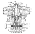
- FIG. 1 shows an embodiment of a high-pressure trunnion-type ball valve according to the present invention
- FIG. 2 shows a separated sectional view of FIG.
- a ball valve main body (hereinafter referred to as a valve main body) 10 is provided with a ball 12 which is a valve body rotatably via a stem 11 inside. Sealing mechanisms 13 for sealing contact are arranged on both sides of the ball 12, and this is a trunnion-type ball valve structure that is particularly suitable for flowing a high-pressure fluid.
- the valve body 10 is composed of a body body 14, which is composed of a body 15 and cap members 16, 16 provided on the primary side and the secondary side of the body 15, respectively.
- a ball 12 and a seal mechanism 13 are housed inside the body main body 14.
- the high pressure in the present embodiment is, for example, 35 MPa or more, and 70 to 105 MPa, specifically 90 MPa is assumed for the piping equipment for the hydrogen station.
- the body 15 is formed in a substantially rectangular shape, and the body body 14 is configured by screwing the cap members 16 and 16 through the screwing portions 16a with the gaskets 17 sandwiched between both sides of the body 15.
- a mounting hole 19 for mounting the seat retainer 18 is provided on the inner peripheral surface of the cap member 16, and the seat retainer 18 is provided in the mounting hole 19 so as to be fitted therein. Further, a seal member 20 can be mounted in the mounting hole 19.
- the mounting hole 19 is formed with an enlarged groove portion 23 having a diameter larger than that of the mounting hole 19, and a spacer 25 formed in a substantially cylindrical shape is attached between the enlarged groove portion 23 and a spring member 22 described later.
- a spring member 22 is mounted in a resilient state between the spacer 25 and the seat retainer 18.
- a female thread portion 24 is formed in communication with the other side of the mounting hole 19, and an external joint (not shown) can be screwed into the female thread portion 24.
- the cap member 16 can be integrated with the body 15 by a joining means such as adhesion or welding.
- the ball 12 is formed using, for example, stainless steel such as SUS316 as a base material, and has a ball surface 12a.
- a seat retainer 18 can be sealed to the ball surface 12a.
- the ball 12 has an upper shaft portion (upper shaft portion) 12b and a lower trunnion (lower shaft portion) 12c.
- the upper shaft portion 12b and the lower shaft portion 12c are attached to the mounting holes of the body 15. It can turn freely by being attached to 15a.
- the fluid can flow when the communication hole 12 d formed in the ball 12 communicates with the internal flow path 28 formed in the seat retainer 18. Yes.
- the base material of the ball 12 is SUS316, the Vickers hardness is Hv200 or less.
- the ball 12 is formed of stainless steel, since the ball 12 is a liquid contact part, it is desirable to use a material free from hydrogen embrittlement.
- a pressure equalizing hole 12e communicating from the communicating hole 12d to the upper surface side of the ball is provided, and the pressure in the cavity when the valve is opened can be released by the pressure equalizing hole 12e. It is like that.
- the seal mechanism 13 includes a seat retainer 18, a spring member 22, and a seal member 20.
- the sheet retainer 18 is formed using, for example, a copper base alloy such as a BeCu alloy (beryllium copper alloy) as a base material.
- a copper base alloy such as a BeCu alloy (beryllium copper alloy) as a base material.
- BeCu alloy beryllium copper alloy
- the base material of the sheet retainer 18 is beryllium copper
- the Vickers hardness after the heat treatment is Hv 360 to 450
- the mechanical properties thereof are, for example, a tensile strength of 1200 to 1500 MPa, a 0.2% proof stress of 1000 to 1400 MPa.
- the sheet retainer is formed of a copper-based alloy, embrittlement due to hydrogen can be prevented.
- the seat retainer 18 it is desirable to perform polishing on the seal surface 18a which is the contact side of the ball surface 12a.
- the base material hardness of the seat retainer 18 is set higher than the base material hardness of the ball 12, and “hardness of diamond-like carbon”> “base material hardness of the seat retainer”> “base material hardness of the ball” Have the relationship. Accordingly, even if diamond-like carbon (DLC), which will be described later, is consumed, the difference in hardness between the DLC on the ball surface 12a and the base material of the seat retainer 18 or the DLC on the ball surface 12a is consumed.
- DLC diamond-like carbon
- BeCu is used for the seat retainer 18 so that the sealing performance can be further maintained. That is, the double that the DLC is provided, the hardness difference is provided between the base material of the seat retainer 18 and the base material of the ball 12, the base material of the seat retainer 18 is a BeCu alloy, The triple setting makes fail-safe so that high-pressure hydrogen does not leak.
- the base material hardness of the ball may be set equal to or higher than the base material hardness of the seat retainer.
- the seat retainer 18 As a specific shape of the seat retainer 18, there are provided an enlarged diameter portion 26 disposed to face the ball 12 and a cylindrical portion 27 having a diameter smaller than that of the enlarged diameter portion 26. As described above, the sealing surface 18a is provided on the surface of the enlarged diameter portion 26 facing the ball 12, and the sealing surface 18a and the ball surface 12a are capable of sealing contact.
- the base material of the seat retainer 18 may be a copper alloy such as aluminum bronze or a material other than a copper base alloy as long as the function as a sliding component can be exhibited. In the present embodiment, since the cylindrical portion of the sheet retainer 18 that is a pressure-resistant sliding component has a small diameter and is thin, a BeCu alloy having high mechanical properties is used to prevent deformation.
- an X axis is provided in the direction of the flow path of the ball 12 from the spherical diameter center point P of the ball surface 12a, and a Y axis intersecting with the X axis is provided.
- Two deviation points (offset points) Q and Q are provided at a predetermined distance H from the spherical diameter center point P in the Y-axis direction.
- each offset point Q by drawing deviation from Q hemisphere with a radius R slightly longer radius R than B of the ball surface 12a at an angle of 180 ° in the opposite direction to the (offset) side S, S respectively, the hemisphere A seal surface 18a having a part of S as a locus surface is formed. That is, in FIG. 4, the seal surface 18 a is a part of a slightly longer radius R locus of the ball surface 12 a drawn from the offset points Q and Q of the predetermined distance H, and this seal surface 18 a is drawn with the radius R. It will be.
- the predetermined distance H of the offset point Q is set so that the seal position T between the seal surface 18a and the ball surface 12a is substantially the center position of the seal surface 18a.
- an internal flow path diameter d N is 10mm ball 12 in FIG. 1, when the spherical diameter D B of the ball surface 12a is ⁇ 20mm of (radius R B is 10mm) is slightly longer radius R (radius R B + [Delta] r)
- an offset point Q having the distance H as ⁇ h is set, and a locus plane is drawn from the offset point Q.
- the predetermined distance H from the spherical diameter center point P of the offset point Q can be appropriately changed according to the spherical diameter of the ball surface 12a. In the present embodiment, the relationship ⁇ r> ⁇ h is set.
- the seal surface 18a of the seat retainer 18 is set with a slightly longer radius than the ball surface 12a without providing the offset point Q, the ball 12 contacts the inner peripheral edge portion of the seal surface 18a of the seat retainer 18. End up. Then, the inner peripheral edge portion comes into contact with the ball surface 12a in a local manner, and there is a high possibility that the DLC is damaged. In order to avoid this, a technique of rounding the inner peripheral edge portion to avoid a local contact is conceivable. However, the position of the ball 12 is shifted in the X-axis direction, and the shaft portion on the top of the ball 12 is New problems arise, such as having to make it thinner.
- the seal position between the seal surface 18a of the seat retainer 18 and the ball surface 12a is set to a substantially central position of the seal surface. Then, the finishing process before the DLC is applied to the ball 12 so that the seat retainer 18 and the ball 12 are sealed with a surface contact seal.
- the present invention has a seal surface abutted by line contact or surface contact, and even in line contact, a contact seal surface having a predetermined width is actually formed.
- the width of the surface contact seal is an annular close contact portion formed substantially parallel to the Y axis, and is set to a width of about 0.5 mm, for example. Since the trunnion type ball valve of the present embodiment is for high pressure, the ball 12 is slightly displaced by the fluid pressure. However, by setting the surface contact seal width as described above, the annular contact portion is maintained.
- the seal position T is set at a substantially central position of the seal surface 12a. Therefore, even when the position of the seal position T is slightly deviated during use of the ball valve, The close contact state is maintained.
- a seal member 20 and backup rings 29 and 30 to be described later are disposed on the cylindrical portion 27 of the seat retainer 18.
- the seat retainer 18 By inserting the cylindrical portion 27 into the mounting hole 19 of the cap member 16, the seat retainer 18 is movable in the flow path direction.
- the sealing member 20 is mounted in close contact with the outer peripheral surface of the cylindrical portion 27, and the cylindrical portion 27 and the mounting hole 19 are sealed by the sealing member 20 when the seat retainer 18 moves in the flow path direction.
- An internal flow path 28 through which high-pressure fluid flows is formed inside the seat retainer 18.
- a coating layer 31 of diamond-like carbon is applied to at least the seal surface 18a of the seat retainer 18 and the ball surface 12a in contact with the seal surface 18a.
- a conforming layer 32 is applied to the surface of one or both of the sealing surface 18a and the ball surface 12a.
- DLC is an amorphous hard film mainly composed of allotropes of hydrocarbons or carbon, and has high hardness and excellent properties such as lubricity, wear resistance, surface smoothness, and chemical stability. .
- a film can be formed by a plasma CVD method or a PVD method.
- the DLC When the DLC is provided by plasma CVD, a raw material gas is converted into plasma in a chamber using a hydrocarbon gas such as acetylene, and vapor phase synthesized hydrocarbon is deposited on the surface of the component. In this case, since hydrogen is contained in the raw material, hydrogen is also contained in DLC.
- the DLC when the DLC is provided by the PVD method, for example, there are a sputtering method and an ion plating method. In this case, the graphite as a raw material is exposed to an ion beam, arc discharge, glow discharge or the like in a vacuum, and scattered carbon atoms are attached to the surface of the component.
- DLC can be provided only with carbon, and hydrogen-free DLC can be applied.
- hydrogen which is a high-pressure fluid
- hydrogen fluid may enter the DLC of the coating layer 31, but the DLC of this embodiment contains hydrogen, and this DLC is There is no risk of further peeling from the base material.
- the Vickers hardness is sufficiently higher than that of the sheet retainer or the base material of the ball, for example, in the range of HV1500 to 3000, and a film thickness of about 2 to 3 ⁇ m and a uniform thickness on the processing surface.
- the conforming layer 32 is provided with an appropriate thickness as necessary.
- the component to which the coating layer 31 of DLC is applied can be used as a high surface pressure sliding component, and the initial conforming performance is improved by providing the conforming layer 32.
- the spring member 22 in the sealing mechanism is made of, for example, a coil spring, and is mounted between the enlarged diameter portion 26 of the seat retainer 18 inserted into the mounting hole 19 and the spacer 25, and the spring member 22 seals the seat retainer 18. A resilient force is applied in the direction of the surface 18a.
- the spring member 22 may be a disc spring.
- the seal member 20 is made of, for example, a rubber O-ring, and is mounted in the mounting hole 19 together with the backup rings 29 and 30, whereby the space between the mounting hole 19 on the body main body 14 side and the outer peripheral surface 18 a of the seat retainer 18. It is arranged.
- the backup ring 29 disposed on the seal member 20 side is formed of, for example, PTFE (polytetrafluoroethylene), and the backup ring 30 disposed outside the backup ring 29 is formed of, for example, PEEK (polyether ether). Ketone).
- the seal member 20 and the backup rings 29 and 30 may be formed of a material other than the above materials, but also in this case, it is preferable to use a soft material similar to rubber or PTFE, By using a soft material, the mounting hole 19 can be easily deformed and mounted.
- the seal member 20 is mounted in the mounting hole 19 with the backup rings 29 and 30 arranged on both sides, and both sides are protected by the backup rings 29 and 30.
- valve main body 10 Due to the sealing function of the ball 12 and the sealing mechanism 13, the valve main body 10 is sealed by the elastic force that the spring member 22 applies to the seat retainer 18 and the fluid pressure set on the inner diameter side of the sealing member 20.
- the high pressure fluid can be sealed by a so-called double seal method using self-tightening force by exerting the pressing force of.
- a lower packing washer 33 On the outer peripheral side of the stem 11, a lower packing washer 33, an inner diameter sealing member 34, an outer diameter sealing member 35, a thrust bearing 36, an upper packing washer 37 that can be fitted from above the lower packing washer 33, a gland 38, and a bush 39 is provided, and the stem 11 is rotatably mounted in the body 15 through these.
- the lower packing washer 33 has a cylindrical portion 40 in which an inner diameter seal member 34 that seals between the stem 11 and the bottom portion 41 on which the inner diameter seal member 34 is placed.
- An annular groove 42 is formed on the outer peripheral side of the cylindrical portion 40, and an outer diameter seal member 35 is attached to the annular groove 42.
- the inner diameter sealing member 34 and the outer diameter sealing member 35 are mounted between the stem 11 and the lower packing washer 33, and the lower packing washer 33 and the body 15, respectively. Leakage of high-pressure fluid from the part is prevented.
- the lower packing washer 33 is disposed on the upper side of the stem 11 via the thrust bearing 36, whereby the stem 11 is rotatable with respect to the inner diameter seal member 34 and the upper packing washer 37 via the thrust bearing 36. It becomes.
- the gland 38 is formed in a substantially cylindrical shape, and has an annular flange portion 43 into which the upper packing washer 37 and the lower packing washer 33 can be fitted, and a lid portion 45 that covers the upper packing washer 37 from above. ing.
- the gland 38 is attached to the mounting recess 46 formed in the body 15 by screwing from the upper side of the upper packing washer 37, houses the inner diameter seal member 34, and the upper and lower packing washers 37 to which the outer diameter seal member 35 is attached. , 33 are pressed in the direction of the thrust bearing 36.
- a bush 39 is mounted on the inner peripheral side of the gland 38, and the upper packing member 37 is pressed against the lower packing washer 33 by the bush 39.
- the bush 39 is provided with PEEK as a material, for example.
- a cover 50 is attached to the body 15 of the valve body 10, and a handle cap 51 and a manual handle 52 are attached via the cover 50.
- the cover 50 is formed in a substantially disc shape, and a bottom surface side is provided with a hook-shaped side surface portion 54 that can be fitted to an annular protrusion 53 formed on the upper surface side of the body 15.
- the counterbore part 55 and the notch part 56 are alternately formed at intervals of 90 °.
- a hole 57 for inserting the handle cap 51 is formed at the center of the cover 50, and a regulating piece (not shown) is formed projectingly into the hole 57, and the stem 11 rotates by this regulating piece. Regulated in the range of °.
- the handle cap 51 is formed in a substantially cylindrical shape having substantially the same diameter as the ground 38, and a locking piece 59 that can be locked to the regulating piece of the cover 50 is formed on the outer peripheral side thereof.
- a fitting hole portion 51a into which the parallel portion 11a formed on the upper end portion of the stem 11 can be fitted is formed.
- the handle cap 51 is connected to the fitting hole portion 51a and the parallel portion 11a. And the stem 11 are integrated.
- the handle cap 51 is provided with an attachment hole 60, while the attachment portion of the handle 52 is provided with an outer diameter that can be fitted into the attachment hole 60.
- a female screw 61 is provided at a position corresponding to the counterbore 55 on the side of the annular projection 53 of the body 15 and the notch 56, and a fixing bolt 62 and a set screw (not shown) are screwed to the female screw 61. It is possible.
- the handle cap 51 is attached to the stem 11 in a predetermined direction by fitting the fitting hole 51a and the parallel portion 11a.
- the cover 50 is fitted to the annular protrusion 53 from above the handle cap 51.
- the handle cap 51 is fixed by screwing the fixing bolt 62 and the set screw to the female screw 61 through the counterbore portion 55 and the notch portion 56 of the cover 50, respectively.
- the handle 52 is operably attached to the upper end side of the stem by inserting the handle 52 into the 60 and fixing it with the fixing bolt 64.
- the locking piece 59 is regulated by coming into contact with the regulating piece, so that the stem 11 can be opened and closed while the rotation of the stem 11 is regulated to 90 °.
- the valve body 10 is provided as a manual valve.
- the high-pressure trunnion type ball valve of the present invention can be automated by an automatic operation actuator such as a pneumatic actuator, as will be described later, in addition to attaching a manual handle as described above.
- the trunnion type ball valve for high pressure of the present invention is provided with a coating layer 31 made of diamond-like carbon on at least the seal surface 18a of the seat retainer 18 and the ball surface 12a in contact with the seal surface 18a. Therefore, when high-pressure fluid such as high-pressure hydrogen gas flows, slidability due to high surface pressure is secured, and scratches occur on either side of the seat retainer 18 and the ball 12. It is possible to improve the operability while ensuring low torque and sealing properties and preventing leakage. By providing the DLC with the coating layer 31 having a film thickness of 2 to 3 ⁇ m, it is possible to maintain the ultraprecision processing of the base material such as sphericity and finish roughness even after coating.
- the ball at an angle of 180 ° in the opposite direction to the offset side from the offset point Q offset by a predetermined distance H in the Y-axis direction intersecting the X-axis that is the flow path direction of the ball 12 from the spherical diameter center point P of the ball surface 12a since constitutes a sealing surface 18a which part of the hemisphere S drawn respectively slightly longer radius R and the trajectory plane than the radius R B of the surface 12a, the sealing position T of the ball surface 12a of the seal face 18a
- the seal surface 12a is set at a substantially central position, and the ball surface 12a and the seal surface 18a are prevented from coming into contact with each other in an inclined state. nowadays prevents leaks.
- the durability of the seat retainer 18 is improved by the rotation of the ball 12 by setting the base material hardness of the seat retainer 18 higher than the base material hardness of the ball 12. It can prevent scratches due to galling. This demonstrates high sealing performance.
- the base material of the seat retainer 18 is a BeCu alloy and the base material of the ball 12 is stainless steel, the adoption of this metal sheet makes it difficult to be affected by changes in the hydrogen temperature and improves durability. Even when the DLC coating layer 31 is depleted, leakage can be avoided by the beryllium layer of the BeCu alloy as the base material of the seat retainer 18.
- the conforming layer 32 is provided on the surface of one or both of the sealing surface 18a and the ball surface 12a, the conforming property between the sealing surface 18a and the ball surface 12a is enhanced to prevent frictional wear.
- the mobility can be improved.
- the familiarity layer 32 increases the degree of adhesion, the sealing performance is also improved.
- valve body 10 of the present invention sets the fluid pressure on the inner diameter side of the seat retainer 18 of the seal mechanism 13, the following self-tightening force can be obtained.
- FIG. 1 and FIG. 5 if the left side of the seat retainer 18 is the primary side and the right side is the secondary side, the seal surface 18a is shown when fluid flows from the primary side to the secondary side as shown by the arrows in FIG.
- the inner diameter ⁇ A, the inner diameter ⁇ D of the seal member 20, the outer diameter ⁇ C of the seal surface 18a, and the outer diameter ⁇ B of the seal member 20 are set such that the inner diameter ⁇ D ⁇ the inner diameter ⁇ A ⁇ the outer diameter ⁇ C ⁇ the outer diameter ⁇ B.
- the seat retainer 18 is pressed against the ball 12 by the fluid pressure in the flow path applied to the area of the inner diameter ⁇ D ⁇ the inner diameter ⁇ A when the valve is closed.
- the seat retainer 18 is pressed against the ball 12 by the fluid pressure in the cavity applied to the area of the outer diameter ⁇ C ⁇ the inner diameter ⁇ D.
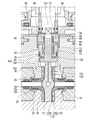
- FIG. 6 shows a second embodiment of the trunnion-type ball valve according to the present invention.
- FIG. 7 shows the main part of FIG. 6, and
- FIG. 8 shows the AA cross section of FIG. The fitting state is shown.
- the same parts as those in the above embodiment are denoted by the same reference numerals, and the description thereof is omitted.
- an upper shaft portion 12b and a lower shaft portion 12c are integrally provided on the ball 12 as in the above-described embodiment, and the upper and lower shaft portions 12b , 12c, the ball 12 is rotatably provided via radial bearings 110, 110.
- a flexible member 110b such as polytetrafluoroethylene (PTFE) is coated on the inner peripheral surface of a rigid cylindrical body 110a such as stainless steel.
- PTFE polytetrafluoroethylene
- the radial bearing 110 is set in a long shape that supports from the vicinity of the spherical portion of the ball 12 to the vicinity of the stem connection portion.
- the present embodiment has a top entry type structure in which the ball 12 is inserted from the upper part of the body 15, the present invention can be applied to a bottom entry type structure in which the ball 12 is inserted from the lower part of the body 15.
- the stem 11 is joined to the upper shaft portion 12b of the ball 12, and the ball 12 is rotatably provided through the rotational force of the stem.
- the stem 11 has a sliding surface 103 in the thrust direction, and a thrust bearing 105 is mounted between the sliding surface 103 and the lower packing washer 33.
- a thrust bearing 105 PTFE is covered with a rigid plate such as a thin stainless steel plate (not shown), and the PTFE comes into contact with the sliding surface 103 of the stem 11 and the lower packing washer 33.
- the stem 11 is also supported in the thrust direction via the thrust bearing 105.
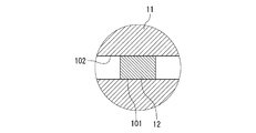
- a parallel two-sided groove 102 is formed at the lower end of the stem 11, and this parallel two-sided groove 102 receives the load when the ball 12 is closed, that is, FIG. Are provided so as to be cut out in the left-right direction.
- a parallel two-surface portion 101 that can be joined to the parallel two-surface groove 102 is formed at the upper end of the upper shaft portion 12 b of the ball 12.
- the stem 11 and the ball 12 are provided so as to be interlocked by the parallel two-plane groove 102 and the parallel two-surface portion 101 in a joined state, and when the ball 12 is pressed by a high-pressure fluid when the valve is closed, the vertical shaft portions 12b and 12c are The ball 12 is supported through a radial bearing 110 in a vertical state in the secondary direction.
- the ball 12 When the pressure of the high-pressure fluid is applied to the ball 12 when the valve is closed, the ball 12 is supported by the upper shaft portion 12b and the lower shaft portion 12c by the radial bearing 110 as described above, but is parallel to the parallel two-surface portion 101. It moves slightly parallel to the stem 11 via the two-sided groove 102. As a result, it is possible to prevent the displacement of the inner diameter sealing member 34 that is a seal for sealing the stem 11, hold the fixed position, and prevent the inclination of the stem 11. For this reason, the sealing function on the outer peripheral side of the stem 11 by the inner diameter sealing member 34 is effectively exhibited.
- the thrust bearing 105 and the radial bearing 110 are pressed and fixed from above by a gland 38 screwed to the body 15. At this time, the upper side of the stem 11 is supported by a pressing bush 39 mounted on the inner peripheral side of the gland 38, and the inner diameter seal member 34 and the outer diameter seal member 35 are mounted at fixed positions.
- the concave parallel two-surface groove 102 is formed on the stem 11 and the convex parallel two-surface portion 101 is formed on the ball 12 has been described.
- the uneven relationship may be reversed, that is, The stem 11 may be provided with a convex parallel two-sided portion, and the ball 12 may be provided with a concave parallel two-sided groove.
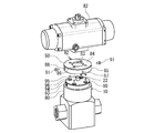
- a pneumatic actuator 82 for automatic operation is attached to the stem upper end portion 11b.
- the high pressure trunnion type ball valve of the present invention has a manual operation handle 52 attached to the upper end portion 11b of the stem 11 to form a manual operation ball valve, or the upper end portion 11b of the stem 11 is formed on the body. It can be connected to an automatic operation actuator 82 mounted on the main body 15 to provide a ball valve for automatic operation.
- the actuator 82 is attached to the body main body 15 via the cover 50. The actuator 82 can accurately control the rotation of the ball 12 supported in a state perpendicular to the secondary direction with a predetermined torque.
- the cover 50 includes a substrate 84 having a mounting opening 83 and a drooping side plate 85.
- the substrate 84 has a bolt through hole 86 formed therein, and the drooping side plate 85 has a positioning groove 87 and a counterbore hole 88 at 90 degrees. It is formed alternately at intervals. As a result, two positioning grooves 87 and counterbore holes 88 are provided with respect to the hanging plate 85.
- the outer peripheral side of the upper part of the shaft mounting portion 80 of the body 15 of the ball valve body 10 is formed in an annular notch, thereby forming an annular protrusion 90.
- female screw portions 93 to which the valve fixing bolt 91 and the mounting pin 92 can be screwed are equally arranged at four positions at intervals of approximately 90 degrees.
- a storage groove 94 is formed on the upper surface of the annular protrusion 90, and a head 96 of an actuator fixing bolt 95 for fixing the cover 50 to the actuator 82 can be stored in the storage groove 94.
- an annular convex portion 97 that can be fitted into a mounting opening 83 formed in the cover 50 is formed.
- a female not shown (not shown) to which an actuator fixing bolt 95 can be screwed. Screws are provided.
- the attachment pin 92 is screwed onto the female thread portion 93 of the shaft mounting portion 80.
- the mounting pins 92 and 92 are fixed to the two opposing female screw portions 93 among the four female screw portions 93 formed at intervals of 90 degrees as shown in the drawing.
- the annular projecting portion 97 of the actuator 82 is fitted and positioned in the mounting opening 83, and the actuator fixing bolt 95 is screwed into the female screw through the actuator fixing bolt 95 from the bolt through hole 86.
- the cover 50 is screwed into the predetermined mounting position.
- the cover 50 integrated with the actuator 82 is attached to the ball valve body 10.
- the annular projection 90 is fitted to the inner peripheral side of the drooping side plate 85 while the mounting pin 92 provided on the outer surface of the upper portion of the shaft mounting portion 80 is locked to the positioning groove 87 to fix the positioning.
- the actuator 82 is mounted at a predetermined position of the shaft mounting portion 80 by placing 50 on the upper surface of the shaft mounting portion 80.
- the convex portion 122 formed on the upper end side of the stem 11 is fitted to the concave portion 121 formed on the lower end side of the output shaft 120 provided in the actuator 82, thereby connecting the output shaft 120 and the stem 11.
- the head 96 of the actuator fixing bolt 95 is stored in the storage groove 94 on the upper surface of the shaft mounting portion.
- the cover 50 can be positioned and fixed to the ball valve main body 10 by screwing the valve fixing bolt 91 to the female threaded portion 93 from the drooping side plate 85, and the actuator 82 is connected to the ball via the cover 50.
- the valve body 10 can be accurately positioned and fixed at a predetermined position.
- the actuator 82 is operated, the ball 12 can be opened and closed accurately. It is also possible to provide four valve fixing bolts 91 in place of the positioning pins.
- the actuator 82 is a so-called spring return type, and a spring member 115 is mounted inside, and a retainer member 116 for preventing the spring member 115 from popping out is provided.
- the retainer member 116 is formed with a projecting abutting portion 117, and the abutting portion 117 contacts both sides of the cylinder 119 when the piston 118 provided therein reciprocates in the cylinder 119.
- the stroke (not shown) of the piston 118 is restricted, and the rotation angle of the output shaft 120 is restricted to a predetermined angle, that is, 90 °.
- FIG. 11 shows a hydrogen station provided with the high-pressure trunnion-type ball valve of the present invention.
- the hydrogen station has a pressure accumulator 70, a compressor 71, a dispenser 72, a precool heat exchanger 73, a quick coupling 74, a filling hose 75, a filling nozzle 76, and an on-vehicle tank 77, which are used as a high-pressure hydrogen supply line 78. Is configured.
- the ball valve of the present invention Since the ball valve of the present invention has a small pressure loss, the pressure loss of the entire system is reduced by providing it on the secondary side of the accumulator 70 or other supply line, which is suitable for the system shown in FIG. is there.
- a manual valve 81 is provided at a connection portion of each unit of the hydrogen station, and an automatic valve 80 is appropriately provided on the primary side or secondary side of each unit to control opening and closing.
- the inside of the pressure accumulator 70 is divided into a plurality of tanks. By switching the valves 80 that connect the tanks and the compressor 71 and the valves 80 that connect the tanks and the dispenser 72 as needed, a predetermined pressure is obtained. While supplying hydrogen to the dispenser from the tank that has reached the tank, the tank that has fallen below the predetermined lower limit pressure is filled with hydrogen from the compressor 71 until the predetermined pressure is reached.
- the hydrogen supply in the system is controlled by a predetermined program, or the hydrogen supply is appropriately controlled according to the vehicle supply amount.
- FIG. 10 is a longitudinal sectional view showing another embodiment of the high-pressure trunnion type ball valve.
- FIG. 1 shows a top entry type ball valve
- FIG. 10 shows a bottom entry type ball valve.
- the ball valve structure shown in FIG. 10 includes the same structure as that of the ball valve shown in FIGS. 1 to 9, and therefore, the same parts are denoted by the same reference numerals and description thereof is omitted.
- cap members 16 and 16 are screwed and fixed to the primary side and the secondary side of the body 150 through screwing portions 16a, respectively. Further, a ball having the stem 11, the upper shaft portion 12 b and the lower shaft portion 12 c is inserted into the mounting hole 150 a of the body 150 from the bottom side of the body 150, and tightened to the protruding portion 203 of the body 150 via the screwing portion 200.
- a bottom entry type ball valve is configured by fixing with a fixing screw 202 having a portion 201.
- a packing 206 having a substantially U-shaped cross section, a metal bush 205, a bearing 204, and a radial bearing 110 (110a, 110b) are mounted in the gap between the stem 11 and the mounting hole 150a into which the ball 12 is inserted.
- reference numeral 207 denotes a space.
- the bottom entry type high-pressure trunnion type ball valve in this example can simplify the seal structure of the stem 11 as compared with the top entry type, and can provide a more compact and robust ball valve.
- the hydrogen durability test was conducted on the ball 12 and the seat retainer 18 of the high pressure trunnion type ball valve of the present invention, and the durability was compared. At this time, the ball 12 was opened and closed while flowing a high-pressure fluid having a temperature of ⁇ 40 ° C. to 85 ° C. under normal temperature, low temperature ( ⁇ 40 ° C.), and high temperature (85 ° C.). Hydrogen gas was used as the high pressure fluid.
- the present invention is particularly suitable for piping equipment such as a hydrogen station through which hydrogen or the like of a high-pressure fluid used in a fuel cell flows, but exhibits excellent sealing performance and torque performance as long as it is a pipeline through which high-pressure fluid flows.
- piping equipment such as a hydrogen station through which hydrogen or the like of a high-pressure fluid used in a fuel cell flows, but exhibits excellent sealing performance and torque performance as long as it is a pipeline through which high-pressure fluid flows.
- it is suitable as a valve in a CNG (Compressed Natural Gas) station or as a high pressure ball valve used in a place where various high pressure fluids flow, such as a pipe valve.
- CNG Compressed Natural Gas
- Ball valve body 11 Stem 12 Ball 12a Ball surface 12b Shaft (upper shaft) 12c trunnion (lower shaft) DESCRIPTION OF SYMBOLS 13 Seal mechanism 14 Body main body 18 Sheet retainer 18a Seal surface 18b Outer peripheral surface 20 Seal member 22 Spring member 31 Coating layer (diamond-like carbon) 32 Alignment layer 52 Handle 82 Actuator 101 Parallel two-sided portion 102 Parallel two-sided groove 103 Sliding surface 110 Radial bearing 110a Rigid cylindrical body H Distance P Spherical diameter center point Q Offset point R Seat R B Ball surface radius S Hemispherical T Seal position
Landscapes
- Engineering & Computer Science (AREA)
- General Engineering & Computer Science (AREA)
- Mechanical Engineering (AREA)
- Taps Or Cocks (AREA)
- Fuel Cell (AREA)
Priority Applications (7)
| Application Number | Priority Date | Filing Date | Title |
|---|---|---|---|
| US14/378,722 US9546736B2 (en) | 2012-02-28 | 2013-02-28 | Trunnion ball valve for high pressure, and hydrogen station |
| NO13754623A NO2821680T3 (https=) | 2012-02-28 | 2013-02-28 | |
| KR1020147021594A KR102039532B1 (ko) | 2012-02-28 | 2013-02-28 | 고압용 트러니언형 볼 밸브 및 수소 스테이션 |
| CA2862411A CA2862411C (en) | 2012-02-28 | 2013-02-28 | Trunnion ball valve for high pressure, and hydrogen station |
| EP13754623.0A EP2821680B1 (en) | 2012-02-28 | 2013-02-28 | Trunnion ball valve for high pressure, and hydrogen station |
| JP2014502361A JP6072763B2 (ja) | 2012-02-28 | 2013-02-28 | 高圧用トラニオン型ボール弁並びに水素ステーション |
| DK13754623.0T DK2821680T3 (en) | 2012-02-28 | 2013-02-28 | HIGH PRESSURE BALL VALVE AND HYDROGEN STATION |
Applications Claiming Priority (4)
| Application Number | Priority Date | Filing Date | Title |
|---|---|---|---|
| JP2012041912 | 2012-02-28 | ||
| JP2012-041912 | 2012-02-28 | ||
| JP2012192124 | 2012-08-31 | ||
| JP2012-192124 | 2012-08-31 |
Publications (1)
| Publication Number | Publication Date |
|---|---|
| WO2013129560A1 true WO2013129560A1 (ja) | 2013-09-06 |
Family
ID=49082751
Family Applications (1)
| Application Number | Title | Priority Date | Filing Date |
|---|---|---|---|
| PCT/JP2013/055367 Ceased WO2013129560A1 (ja) | 2012-02-28 | 2013-02-28 | 高圧用トラニオン型ボール弁並びに水素ステーション |
Country Status (8)
| Country | Link |
|---|---|
| US (1) | US9546736B2 (https=) |
| EP (1) | EP2821680B1 (https=) |
| JP (2) | JP6072763B2 (https=) |
| KR (1) | KR102039532B1 (https=) |
| CA (1) | CA2862411C (https=) |
| DK (1) | DK2821680T3 (https=) |
| NO (1) | NO2821680T3 (https=) |
| WO (1) | WO2013129560A1 (https=) |
Cited By (9)
| Publication number | Priority date | Publication date | Assignee | Title |
|---|---|---|---|---|
| KR20150128071A (ko) * | 2014-05-08 | 2015-11-18 | 김충호 | 개폐가 용이한 유체 밸브 장치의 제작 방법 및 이에 의하여 제작된 유체 밸브 장치 |
| WO2016067737A1 (ja) * | 2014-10-28 | 2016-05-06 | 株式会社キッツ | トラニオン型ボールバルブ |
| JP2016084905A (ja) * | 2014-10-28 | 2016-05-19 | 株式会社キッツ | トラニオン型ボールバルブ |
| KR20170024006A (ko) | 2014-06-30 | 2017-03-06 | 가부시키가이샤 기츠 | 볼 밸브용 볼 시트의 고착 구조와 그 고착 방법 및 트러니언형 볼 밸브와 이 밸브를 사용한 수소 스테이션 |
| JP2017145472A (ja) * | 2016-02-18 | 2017-08-24 | 日本碍子株式会社 | 耐水素部材及び耐水素部材の使用方法 |
| JP2018080724A (ja) * | 2016-11-15 | 2018-05-24 | 日立オートモティブシステムズ株式会社 | 制御弁 |
| JP2018179176A (ja) * | 2017-04-14 | 2018-11-15 | 株式会社キッツ | 高圧用トラニオン型ボール弁およびこれを用いた水素ステーション |
| JP2018194171A (ja) * | 2017-05-12 | 2018-12-06 | 京セラ株式会社 | 摺動装置 |
| CN110778737A (zh) * | 2019-10-16 | 2020-02-11 | 得威阀门有限公司 | 多道密封面衬氟球阀 |
Families Citing this family (28)
| Publication number | Priority date | Publication date | Assignee | Title |
|---|---|---|---|---|
| US10718468B2 (en) | 2015-04-24 | 2020-07-21 | Cmd Corporation | Method and apparatus for dispensing gaseous fuel to a vehicle |
| CN105065760B (zh) * | 2015-08-03 | 2017-08-25 | 海特克液压有限公司 | 一种手动阀的拨杆回中装置 |
| US20170286654A1 (en) * | 2016-03-29 | 2017-10-05 | Coverquick, Inc. | System and method for smart weapon implementation and deployment |
| FR3052526B1 (fr) * | 2016-06-13 | 2018-11-23 | Valeo Systemes De Controle Moteur | Vanne de controle d'un debit de fluide |
| DE102017201300A1 (de) * | 2017-01-27 | 2018-08-02 | Robert Bosch Gmbh | Magnetventil, Brennkraftmaschine mit Magnetventil und Verfahren zur Herstellung eines Magnetventils |
| CN107420573B (zh) * | 2017-06-26 | 2023-11-24 | 开封瑞科阀门有限公司 | 一种预紧补偿移动阀座耐高温高压双向硬密封旋球阀 |
| KR101825220B1 (ko) * | 2017-08-07 | 2018-02-02 | (주)케이에스티플랜트 | 마이크로합금화 층이 형성된 메탈시트 볼밸브 장치 및 그 제작 방법 |
| EP3695145B1 (en) | 2017-10-10 | 2024-03-06 | Cameron Technologies Limited | Contoured integrated seat for ball valve |
| RU181391U1 (ru) * | 2017-11-07 | 2018-07-11 | Федеральное государственное бюджетное образовательное учреждение высшего образования "Кубанский государственный технологический университет" (ФГБОУ ВО "КубГТУ") | Шиберная задвижка с многослойным покрытием |
| RU184991U1 (ru) * | 2017-12-27 | 2018-11-15 | Алексей Сергеевич Тимохин | Шаровой кран |
| RU184990U1 (ru) * | 2017-12-27 | 2018-11-15 | Алексей Сергеевич Тимохин | Шаровой кран |
| US10900579B2 (en) * | 2018-03-21 | 2021-01-26 | Paul M. Cordua | Riser valve manifold |
| CN108644456A (zh) * | 2018-05-16 | 2018-10-12 | 芜湖市艾德森自动化设备有限公司 | 一种高密封防锈蚀阀杆 |
| US10816102B2 (en) * | 2018-08-01 | 2020-10-27 | General Electric Company | Erosion resistant steam valve |
| JP7213033B2 (ja) * | 2018-08-06 | 2023-01-26 | 株式会社キッツエスシーティー | 高圧用トラニオン型ボール弁及びこれを用いた水素ステーション |
| CN108999994B (zh) * | 2018-10-10 | 2020-09-08 | 江山市志成阀门有限公司 | 一种球阀的加工工艺 |
| US12259064B2 (en) * | 2018-11-01 | 2025-03-25 | Oil States Energy Services, L.L.C. | Valve with pressure differential seating |
| US10995871B2 (en) | 2018-11-07 | 2021-05-04 | Cameron International Corporation | Hard and lubricious valve surfaces, material compositions and sequences of manufacturing |
| JP7381273B2 (ja) * | 2019-09-27 | 2023-11-15 | 株式会社キッツエスシーティー | ボールバルブ及びボールバルブとアクチュエータの直付方法 |
| KR102292754B1 (ko) * | 2020-06-25 | 2021-08-25 | 티에스모스트 주식회사 | 볼 밸브 |
| CN111911649B (zh) * | 2020-07-17 | 2022-03-11 | 沈阳航天新光集团有限公司 | 气动球阀 |
| CN112361025B (zh) * | 2020-11-25 | 2021-08-06 | 浙江石化阀门有限公司 | 一种快开高温球面密封切断阀的快开机构 |
| US11686404B2 (en) * | 2020-12-11 | 2023-06-27 | Dresser, Llc | Reducing noise in ball valves |
| KR102259180B1 (ko) * | 2021-01-05 | 2021-05-31 | 김충호 | 밸브등급 4500 이하의 고온 및 고압 유체용 분해정비형 메탈 볼밸브 |
| GB2605945B (en) * | 2021-03-15 | 2026-03-11 | Jb Valves Ltd | Valve apparatus |
| CN113757401B (zh) * | 2021-09-07 | 2022-04-22 | 哈电集团哈尔滨电站阀门有限公司 | 一种能够防止楔死的手动楔式闸阀 |
| CN115451148B (zh) * | 2022-09-21 | 2025-09-26 | 慎江阀门有限公司 | 一种耐磨球阀及碳化钨、dlc复合涂层的喷涂方法 |
| KR102763878B1 (ko) * | 2022-10-06 | 2025-02-07 | 김성탄 | 수소 디스펜서 |
Citations (10)
| Publication number | Priority date | Publication date | Assignee | Title |
|---|---|---|---|---|
| JPH02286973A (ja) * | 1989-04-28 | 1990-11-27 | Keihin Seiki Mfg Co Ltd | ボール弁 |
| JPH07501127A (ja) * | 1991-11-04 | 1995-02-02 | ファイク、コーポレーション | 開閉位置間のボールバルブ回転手段 |
| JPH08178091A (ja) * | 1994-12-27 | 1996-07-12 | Kyocera Corp | ディスクバルブ |
| JPH08261338A (ja) * | 1995-03-24 | 1996-10-11 | Kitz Corp | ボールバルブ |
| JP2004076884A (ja) | 2002-08-21 | 2004-03-11 | Konan Electric Co Ltd | 高硬度用ボール弁 |
| JP2007535648A (ja) | 2004-04-30 | 2007-12-06 | シークアル テクノロジーズ, インコーポレイテッド | 流れ制御のためのニードルバルブ |
| US20100200791A1 (en) * | 2009-02-07 | 2010-08-12 | Victaulic Company | Valve Having High Pressure and Low Pressure Seals |
| JP2011001598A (ja) * | 2009-06-18 | 2011-01-06 | Jtekt Corp | 摺動部材 |
| JP2011174569A (ja) | 2010-02-25 | 2011-09-08 | Mitsubishi Materials Corp | 電磁弁 |
| JP2012013141A (ja) | 2010-06-30 | 2012-01-19 | Kitz Corp | トラニオン型ボール弁 |
Family Cites Families (9)
| Publication number | Priority date | Publication date | Assignee | Title |
|---|---|---|---|---|
| US3047007A (en) * | 1959-04-01 | 1962-07-31 | Lunkenheimer Co | Ball valve |
| US3174495A (en) * | 1962-11-16 | 1965-03-23 | Acf Ind Inc | Fire safe ball valve |
| US4572239A (en) * | 1981-08-28 | 1986-02-25 | Whitey Co. | High pressure ball valve |
| DE4436202A1 (de) * | 1994-09-29 | 1996-04-11 | Rautenkranz Int Hermann | Kellyhahn mit doppelt gelagertem Kugelküken |
| JP3601554B2 (ja) * | 1995-08-11 | 2004-12-15 | アイシン・エィ・ダブリュ株式会社 | 電磁式圧力調整弁 |
| KR20040082743A (ko) * | 2003-03-20 | 2004-09-30 | 안정오 | 개폐밸브용 볼의 제조방법 및 그 볼 |
| US8146889B2 (en) * | 2004-08-27 | 2012-04-03 | Vetco Gray Inc. | Low friction coatings for dynamically engaging load bearing surfaces |
| JP2006144920A (ja) * | 2004-11-19 | 2006-06-08 | Flo-Tec Ltd | ボールバルブ |
| CA2619331A1 (en) * | 2007-01-31 | 2008-07-31 | Scientific Valve And Seal, Lp | Coatings, their production and use |
-
2013
- 2013-02-28 NO NO13754623A patent/NO2821680T3/no unknown
- 2013-02-28 WO PCT/JP2013/055367 patent/WO2013129560A1/ja not_active Ceased
- 2013-02-28 EP EP13754623.0A patent/EP2821680B1/en active Active
- 2013-02-28 DK DK13754623.0T patent/DK2821680T3/en active
- 2013-02-28 CA CA2862411A patent/CA2862411C/en active Active
- 2013-02-28 US US14/378,722 patent/US9546736B2/en active Active
- 2013-02-28 JP JP2014502361A patent/JP6072763B2/ja active Active
- 2013-02-28 KR KR1020147021594A patent/KR102039532B1/ko active Active
-
2016
- 2016-12-28 JP JP2016255527A patent/JP6430474B2/ja active Active
Patent Citations (10)
| Publication number | Priority date | Publication date | Assignee | Title |
|---|---|---|---|---|
| JPH02286973A (ja) * | 1989-04-28 | 1990-11-27 | Keihin Seiki Mfg Co Ltd | ボール弁 |
| JPH07501127A (ja) * | 1991-11-04 | 1995-02-02 | ファイク、コーポレーション | 開閉位置間のボールバルブ回転手段 |
| JPH08178091A (ja) * | 1994-12-27 | 1996-07-12 | Kyocera Corp | ディスクバルブ |
| JPH08261338A (ja) * | 1995-03-24 | 1996-10-11 | Kitz Corp | ボールバルブ |
| JP2004076884A (ja) | 2002-08-21 | 2004-03-11 | Konan Electric Co Ltd | 高硬度用ボール弁 |
| JP2007535648A (ja) | 2004-04-30 | 2007-12-06 | シークアル テクノロジーズ, インコーポレイテッド | 流れ制御のためのニードルバルブ |
| US20100200791A1 (en) * | 2009-02-07 | 2010-08-12 | Victaulic Company | Valve Having High Pressure and Low Pressure Seals |
| JP2011001598A (ja) * | 2009-06-18 | 2011-01-06 | Jtekt Corp | 摺動部材 |
| JP2011174569A (ja) | 2010-02-25 | 2011-09-08 | Mitsubishi Materials Corp | 電磁弁 |
| JP2012013141A (ja) | 2010-06-30 | 2012-01-19 | Kitz Corp | トラニオン型ボール弁 |
Cited By (15)
| Publication number | Priority date | Publication date | Assignee | Title |
|---|---|---|---|---|
| KR101579600B1 (ko) * | 2014-05-08 | 2015-12-22 | 김충호 | 개폐가 용이한 유체 밸브 장치의 제작 방법 및 이에 의하여 제작된 유체 밸브 장치 |
| KR20150128071A (ko) * | 2014-05-08 | 2015-11-18 | 김충호 | 개폐가 용이한 유체 밸브 장치의 제작 방법 및 이에 의하여 제작된 유체 밸브 장치 |
| EP3150886A4 (en) * | 2014-06-30 | 2018-05-23 | Kitz Corporation | Structure and method for fixing ball seat for ball valve, trunnion-type ball valve, and hydrogen station using said valve |
| KR102335446B1 (ko) * | 2014-06-30 | 2021-12-03 | 가부시키가이샤 기츠 | 볼 밸브용 볼 시트의 고착 구조와 그 고착 방법 및 트러니언형 볼 밸브와 이 밸브를 사용한 수소 스테이션 |
| KR20170024006A (ko) | 2014-06-30 | 2017-03-06 | 가부시키가이샤 기츠 | 볼 밸브용 볼 시트의 고착 구조와 그 고착 방법 및 트러니언형 볼 밸브와 이 밸브를 사용한 수소 스테이션 |
| US10465804B2 (en) | 2014-06-30 | 2019-11-05 | Kitz Corporation | Structure and method for fastening ball seat for ball valve, trunnion ball valve, and hydrogen station using the ball valve |
| JP2016084905A (ja) * | 2014-10-28 | 2016-05-19 | 株式会社キッツ | トラニオン型ボールバルブ |
| US10018276B2 (en) | 2014-10-28 | 2018-07-10 | Kitz Corporation | Trunnion-type ball valve |
| WO2016067737A1 (ja) * | 2014-10-28 | 2016-05-06 | 株式会社キッツ | トラニオン型ボールバルブ |
| JP2017145472A (ja) * | 2016-02-18 | 2017-08-24 | 日本碍子株式会社 | 耐水素部材及び耐水素部材の使用方法 |
| JP2018080724A (ja) * | 2016-11-15 | 2018-05-24 | 日立オートモティブシステムズ株式会社 | 制御弁 |
| JP2018179176A (ja) * | 2017-04-14 | 2018-11-15 | 株式会社キッツ | 高圧用トラニオン型ボール弁およびこれを用いた水素ステーション |
| JP2018194171A (ja) * | 2017-05-12 | 2018-12-06 | 京セラ株式会社 | 摺動装置 |
| JP7141633B2 (ja) | 2017-05-12 | 2022-09-26 | 京セラ株式会社 | 摺動装置 |
| CN110778737A (zh) * | 2019-10-16 | 2020-02-11 | 得威阀门有限公司 | 多道密封面衬氟球阀 |
Also Published As
| Publication number | Publication date |
|---|---|
| NO2821680T3 (https=) | 2018-10-06 |
| CA2862411C (en) | 2020-03-10 |
| JP6430474B2 (ja) | 2018-11-28 |
| CA2862411A1 (en) | 2013-09-06 |
| JP6072763B2 (ja) | 2017-02-01 |
| JPWO2013129560A1 (ja) | 2015-07-30 |
| EP2821680A4 (en) | 2015-11-11 |
| US20160025231A1 (en) | 2016-01-28 |
| EP2821680A1 (en) | 2015-01-07 |
| KR20140128983A (ko) | 2014-11-06 |
| KR102039532B1 (ko) | 2019-11-01 |
| EP2821680B1 (en) | 2018-05-09 |
| DK2821680T3 (en) | 2018-06-14 |
| JP2017116105A (ja) | 2017-06-29 |
| US9546736B2 (en) | 2017-01-17 |
Similar Documents
| Publication | Publication Date | Title |
|---|---|---|
| JP6430474B2 (ja) | 高圧用トラニオン型ボール弁並びに水素ステーション | |
| JP6650500B2 (ja) | 高圧用トラニオン型ボール弁およびこれを用いた水素ステーション | |
| US20200018403A1 (en) | Extreme service plug valve | |
| GB2526211A (en) | Ball valve | |
| JP5689621B2 (ja) | 高圧用回転弁の軸封構造 | |
| JPH0213192B2 (https=) | ||
| JP2012013141A (ja) | トラニオン型ボール弁 | |
| US5478047A (en) | Flexible seating structure for valves | |
| US10267424B2 (en) | Butterfly valve seat with seat cover | |
| JP6745605B2 (ja) | 高圧用トラニオン型ボール弁およびこれを用いた水素ステーション | |
| JP7658552B2 (ja) | 流量制御用三方弁及び温度制御装置 | |
| CN224003198U (zh) | 一种带活载荷的填料密封系统及c型球阀 | |
| JP6865623B2 (ja) | 高圧用トラニオン型ボール弁およびこれを用いた水素ステーション | |
| CN219639473U (zh) | 一种具有复合阀座结构的蝶阀 | |
| CN219013418U (zh) | 一种耐低温球阀 | |
| JP2001041328A (ja) | 弁棒の取り付け位置を弁体中央部から5%以上離し偏心させたバタフライ弁 | |
| JP2023133045A (ja) | ボール弁用弁座及びボール弁 | |
| CN117329321A (zh) | 双球双填料高频快开球阀 | |
| CN118881748A (zh) | 一种低摩擦膨胀密封蝶阀 |
Legal Events
| Date | Code | Title | Description |
|---|---|---|---|
| 121 | Ep: the epo has been informed by wipo that ep was designated in this application |
Ref document number: 13754623 Country of ref document: EP Kind code of ref document: A1 |
|
| ENP | Entry into the national phase |
Ref document number: 2014502361 Country of ref document: JP Kind code of ref document: A |
|
| WWE | Wipo information: entry into national phase |
Ref document number: 2013754623 Country of ref document: EP |
|
| ENP | Entry into the national phase |
Ref document number: 2862411 Country of ref document: CA |
|
| ENP | Entry into the national phase |
Ref document number: 20147021594 Country of ref document: KR Kind code of ref document: A |
|
| WWE | Wipo information: entry into national phase |
Ref document number: 14378722 Country of ref document: US |
|
| NENP | Non-entry into the national phase |
Ref country code: DE |