EP2821680A1 - Trunnion ball valve for high pressure, and hydrogen station - Google Patents
Trunnion ball valve for high pressure, and hydrogen station Download PDFInfo
- Publication number
- EP2821680A1 EP2821680A1 EP13754623.0A EP13754623A EP2821680A1 EP 2821680 A1 EP2821680 A1 EP 2821680A1 EP 13754623 A EP13754623 A EP 13754623A EP 2821680 A1 EP2821680 A1 EP 2821680A1
- Authority
- EP
- European Patent Office
- Prior art keywords
- ball
- sealing
- high pressure
- ball valve
- trunnion
- Prior art date
- Legal status (The legal status is an assumption and is not a legal conclusion. Google has not performed a legal analysis and makes no representation as to the accuracy of the status listed.)
- Granted
Links
- 229910052739 hydrogen Inorganic materials 0.000 title claims abstract description 49
- 239000001257 hydrogen Substances 0.000 title claims abstract description 49
- UFHFLCQGNIYNRP-UHFFFAOYSA-N Hydrogen Chemical compound [H][H] UFHFLCQGNIYNRP-UHFFFAOYSA-N 0.000 title claims abstract description 48
- 238000007789 sealing Methods 0.000 claims abstract description 171
- OKTJSMMVPCPJKN-UHFFFAOYSA-N Carbon Chemical compound [C] OKTJSMMVPCPJKN-UHFFFAOYSA-N 0.000 claims abstract description 22
- 229910052799 carbon Inorganic materials 0.000 claims abstract description 21
- 239000011247 coating layer Substances 0.000 claims abstract description 18
- 230000007246 mechanism Effects 0.000 claims abstract description 14
- 239000012530 fluid Substances 0.000 claims description 45
- 239000000463 material Substances 0.000 claims description 44
- 239000010410 layer Substances 0.000 claims description 13
- 230000002093 peripheral effect Effects 0.000 claims description 12
- 229920001343 polytetrafluoroethylene Polymers 0.000 claims description 12
- 239000004810 polytetrafluoroethylene Substances 0.000 claims description 12
- 229910045601 alloy Inorganic materials 0.000 claims description 11
- 239000000956 alloy Substances 0.000 claims description 11
- 239000010935 stainless steel Substances 0.000 claims description 8
- 229910001220 stainless steel Inorganic materials 0.000 claims description 8
- -1 polytetrafluoroethylene Polymers 0.000 claims description 6
- 238000012856 packing Methods 0.000 description 23
- 238000000034 method Methods 0.000 description 9
- 210000004907 gland Anatomy 0.000 description 7
- 230000001105 regulatory effect Effects 0.000 description 6
- RYGMFSIKBFXOCR-UHFFFAOYSA-N Copper Chemical compound [Cu] RYGMFSIKBFXOCR-UHFFFAOYSA-N 0.000 description 5
- 239000004696 Poly ether ether ketone Substances 0.000 description 5
- 229910052802 copper Inorganic materials 0.000 description 5
- 239000010949 copper Substances 0.000 description 5
- 229920002530 polyetherether ketone Polymers 0.000 description 5
- DMFGNRRURHSENX-UHFFFAOYSA-N beryllium copper Chemical compound [Be].[Cu] DMFGNRRURHSENX-UHFFFAOYSA-N 0.000 description 4
- 238000000576 coating method Methods 0.000 description 4
- 239000007789 gas Substances 0.000 description 4
- 239000004215 Carbon black (E152) Substances 0.000 description 3
- 229910000881 Cu alloy Inorganic materials 0.000 description 3
- 238000005299 abrasion Methods 0.000 description 3
- 239000011248 coating agent Substances 0.000 description 3
- 238000004891 communication Methods 0.000 description 3
- 230000000694 effects Effects 0.000 description 3
- 230000001747 exhibiting effect Effects 0.000 description 3
- 229930195733 hydrocarbon Natural products 0.000 description 3
- 150000002430 hydrocarbons Chemical class 0.000 description 3
- 150000002431 hydrogen Chemical class 0.000 description 3
- 229910052751 metal Inorganic materials 0.000 description 3
- 239000002184 metal Substances 0.000 description 3
- 125000006850 spacer group Chemical group 0.000 description 3
- 229910052790 beryllium Inorganic materials 0.000 description 2
- ATBAMAFKBVZNFJ-UHFFFAOYSA-N beryllium atom Chemical compound [Be] ATBAMAFKBVZNFJ-UHFFFAOYSA-N 0.000 description 2
- 230000008859 change Effects 0.000 description 2
- 238000010586 diagram Methods 0.000 description 2
- 239000000446 fuel Substances 0.000 description 2
- 238000010438 heat treatment Methods 0.000 description 2
- 230000006872 improvement Effects 0.000 description 2
- VNWKTOKETHGBQD-UHFFFAOYSA-N methane Chemical compound C VNWKTOKETHGBQD-UHFFFAOYSA-N 0.000 description 2
- 238000005240 physical vapour deposition Methods 0.000 description 2
- 238000005268 plasma chemical vapour deposition Methods 0.000 description 2
- 238000003825 pressing Methods 0.000 description 2
- 238000012545 processing Methods 0.000 description 2
- 239000011347 resin Substances 0.000 description 2
- 229920005989 resin Polymers 0.000 description 2
- 239000007779 soft material Substances 0.000 description 2
- 239000000758 substrate Substances 0.000 description 2
- 238000003466 welding Methods 0.000 description 2
- 229910000906 Bronze Inorganic materials 0.000 description 1
- 230000005856 abnormality Effects 0.000 description 1
- 229910002065 alloy metal Inorganic materials 0.000 description 1
- HSFWRNGVRCDJHI-UHFFFAOYSA-N alpha-acetylene Natural products C#C HSFWRNGVRCDJHI-UHFFFAOYSA-N 0.000 description 1
- 229910052782 aluminium Inorganic materials 0.000 description 1
- XAGFODPZIPBFFR-UHFFFAOYSA-N aluminium Chemical compound [Al] XAGFODPZIPBFFR-UHFFFAOYSA-N 0.000 description 1
- 239000010974 bronze Substances 0.000 description 1
- 125000004432 carbon atom Chemical group C* 0.000 description 1
- 230000001276 controlling effect Effects 0.000 description 1
- KUNSUQLRTQLHQQ-UHFFFAOYSA-N copper tin Chemical compound [Cu].[Sn] KUNSUQLRTQLHQQ-UHFFFAOYSA-N 0.000 description 1
- 238000000151 deposition Methods 0.000 description 1
- 230000006866 deterioration Effects 0.000 description 1
- 238000010891 electric arc Methods 0.000 description 1
- 125000002534 ethynyl group Chemical group [H]C#C* 0.000 description 1
- 238000007730 finishing process Methods 0.000 description 1
- 229910002804 graphite Inorganic materials 0.000 description 1
- 239000010439 graphite Substances 0.000 description 1
- 238000003780 insertion Methods 0.000 description 1
- 230000037431 insertion Effects 0.000 description 1
- 238000007733 ion plating Methods 0.000 description 1
- 238000010884 ion-beam technique Methods 0.000 description 1
- 238000003754 machining Methods 0.000 description 1
- 238000012423 maintenance Methods 0.000 description 1
- 239000003345 natural gas Substances 0.000 description 1
- 230000008569 process Effects 0.000 description 1
- 238000004544 sputter deposition Methods 0.000 description 1
- 238000005482 strain hardening Methods 0.000 description 1
- 239000000126 substance Substances 0.000 description 1
- 238000012360 testing method Methods 0.000 description 1
- 238000013519 translation Methods 0.000 description 1
- XLYOFNOQVPJJNP-UHFFFAOYSA-N water Substances O XLYOFNOQVPJJNP-UHFFFAOYSA-N 0.000 description 1
Images


Classifications
-
- F—MECHANICAL ENGINEERING; LIGHTING; HEATING; WEAPONS; BLASTING
- F16—ENGINEERING ELEMENTS AND UNITS; GENERAL MEASURES FOR PRODUCING AND MAINTAINING EFFECTIVE FUNCTIONING OF MACHINES OR INSTALLATIONS; THERMAL INSULATION IN GENERAL
- F16K—VALVES; TAPS; COCKS; ACTUATING-FLOATS; DEVICES FOR VENTING OR AERATING
- F16K5/00—Plug valves; Taps or cocks comprising only cut-off apparatus having at least one of the sealing faces shaped as a more or less complete surface of a solid of revolution, the opening and closing movement being predominantly rotary
- F16K5/06—Plug valves; Taps or cocks comprising only cut-off apparatus having at least one of the sealing faces shaped as a more or less complete surface of a solid of revolution, the opening and closing movement being predominantly rotary with plugs having spherical surfaces; Packings therefor
- F16K5/0663—Packings
-
- F—MECHANICAL ENGINEERING; LIGHTING; HEATING; WEAPONS; BLASTING
- F16—ENGINEERING ELEMENTS AND UNITS; GENERAL MEASURES FOR PRODUCING AND MAINTAINING EFFECTIVE FUNCTIONING OF MACHINES OR INSTALLATIONS; THERMAL INSULATION IN GENERAL
- F16K—VALVES; TAPS; COCKS; ACTUATING-FLOATS; DEVICES FOR VENTING OR AERATING
- F16K25/00—Details relating to contact between valve members and seats
- F16K25/005—Particular materials for seats or closure elements
-
- F—MECHANICAL ENGINEERING; LIGHTING; HEATING; WEAPONS; BLASTING
- F16—ENGINEERING ELEMENTS AND UNITS; GENERAL MEASURES FOR PRODUCING AND MAINTAINING EFFECTIVE FUNCTIONING OF MACHINES OR INSTALLATIONS; THERMAL INSULATION IN GENERAL
- F16K—VALVES; TAPS; COCKS; ACTUATING-FLOATS; DEVICES FOR VENTING OR AERATING
- F16K27/00—Construction of housing; Use of materials therefor
- F16K27/06—Construction of housing; Use of materials therefor of taps or cocks
- F16K27/067—Construction of housing; Use of materials therefor of taps or cocks with spherical plugs
-
- F—MECHANICAL ENGINEERING; LIGHTING; HEATING; WEAPONS; BLASTING
- F16—ENGINEERING ELEMENTS AND UNITS; GENERAL MEASURES FOR PRODUCING AND MAINTAINING EFFECTIVE FUNCTIONING OF MACHINES OR INSTALLATIONS; THERMAL INSULATION IN GENERAL
- F16K—VALVES; TAPS; COCKS; ACTUATING-FLOATS; DEVICES FOR VENTING OR AERATING
- F16K31/00—Actuating devices; Operating means; Releasing devices
- F16K31/44—Mechanical actuating means
- F16K31/60—Handles
-
- F—MECHANICAL ENGINEERING; LIGHTING; HEATING; WEAPONS; BLASTING
- F16—ENGINEERING ELEMENTS AND UNITS; GENERAL MEASURES FOR PRODUCING AND MAINTAINING EFFECTIVE FUNCTIONING OF MACHINES OR INSTALLATIONS; THERMAL INSULATION IN GENERAL
- F16K—VALVES; TAPS; COCKS; ACTUATING-FLOATS; DEVICES FOR VENTING OR AERATING
- F16K5/00—Plug valves; Taps or cocks comprising only cut-off apparatus having at least one of the sealing faces shaped as a more or less complete surface of a solid of revolution, the opening and closing movement being predominantly rotary
- F16K5/06—Plug valves; Taps or cocks comprising only cut-off apparatus having at least one of the sealing faces shaped as a more or less complete surface of a solid of revolution, the opening and closing movement being predominantly rotary with plugs having spherical surfaces; Packings therefor
- F16K5/0626—Easy mounting or dismounting means
- F16K5/0636—Easy mounting or dismounting means the spherical plug being insertable from the top of the housing
-
- F—MECHANICAL ENGINEERING; LIGHTING; HEATING; WEAPONS; BLASTING
- F16—ENGINEERING ELEMENTS AND UNITS; GENERAL MEASURES FOR PRODUCING AND MAINTAINING EFFECTIVE FUNCTIONING OF MACHINES OR INSTALLATIONS; THERMAL INSULATION IN GENERAL
- F16K—VALVES; TAPS; COCKS; ACTUATING-FLOATS; DEVICES FOR VENTING OR AERATING
- F16K5/00—Plug valves; Taps or cocks comprising only cut-off apparatus having at least one of the sealing faces shaped as a more or less complete surface of a solid of revolution, the opening and closing movement being predominantly rotary
- F16K5/06—Plug valves; Taps or cocks comprising only cut-off apparatus having at least one of the sealing faces shaped as a more or less complete surface of a solid of revolution, the opening and closing movement being predominantly rotary with plugs having spherical surfaces; Packings therefor
- F16K5/0647—Spindles or actuating means
-
- F—MECHANICAL ENGINEERING; LIGHTING; HEATING; WEAPONS; BLASTING
- F16—ENGINEERING ELEMENTS AND UNITS; GENERAL MEASURES FOR PRODUCING AND MAINTAINING EFFECTIVE FUNCTIONING OF MACHINES OR INSTALLATIONS; THERMAL INSULATION IN GENERAL
- F16K—VALVES; TAPS; COCKS; ACTUATING-FLOATS; DEVICES FOR VENTING OR AERATING
- F16K5/00—Plug valves; Taps or cocks comprising only cut-off apparatus having at least one of the sealing faces shaped as a more or less complete surface of a solid of revolution, the opening and closing movement being predominantly rotary
- F16K5/06—Plug valves; Taps or cocks comprising only cut-off apparatus having at least one of the sealing faces shaped as a more or less complete surface of a solid of revolution, the opening and closing movement being predominantly rotary with plugs having spherical surfaces; Packings therefor
- F16K5/0657—Particular coverings or materials
-
- F—MECHANICAL ENGINEERING; LIGHTING; HEATING; WEAPONS; BLASTING
- F16—ENGINEERING ELEMENTS AND UNITS; GENERAL MEASURES FOR PRODUCING AND MAINTAINING EFFECTIVE FUNCTIONING OF MACHINES OR INSTALLATIONS; THERMAL INSULATION IN GENERAL
- F16K—VALVES; TAPS; COCKS; ACTUATING-FLOATS; DEVICES FOR VENTING OR AERATING
- F16K5/00—Plug valves; Taps or cocks comprising only cut-off apparatus having at least one of the sealing faces shaped as a more or less complete surface of a solid of revolution, the opening and closing movement being predominantly rotary
- F16K5/06—Plug valves; Taps or cocks comprising only cut-off apparatus having at least one of the sealing faces shaped as a more or less complete surface of a solid of revolution, the opening and closing movement being predominantly rotary with plugs having spherical surfaces; Packings therefor
- F16K5/0663—Packings
- F16K5/0668—Single packings
-
- F—MECHANICAL ENGINEERING; LIGHTING; HEATING; WEAPONS; BLASTING
- F16—ENGINEERING ELEMENTS AND UNITS; GENERAL MEASURES FOR PRODUCING AND MAINTAINING EFFECTIVE FUNCTIONING OF MACHINES OR INSTALLATIONS; THERMAL INSULATION IN GENERAL
- F16K—VALVES; TAPS; COCKS; ACTUATING-FLOATS; DEVICES FOR VENTING OR AERATING
- F16K5/00—Plug valves; Taps or cocks comprising only cut-off apparatus having at least one of the sealing faces shaped as a more or less complete surface of a solid of revolution, the opening and closing movement being predominantly rotary
- F16K5/08—Details
- F16K5/14—Special arrangements for separating the sealing faces or for pressing them together
- F16K5/20—Special arrangements for separating the sealing faces or for pressing them together for plugs with spherical surfaces
- F16K5/201—Special arrangements for separating the sealing faces or for pressing them together for plugs with spherical surfaces with the housing or parts of the housing mechanically pressing the seal against the plug
-
- F—MECHANICAL ENGINEERING; LIGHTING; HEATING; WEAPONS; BLASTING
- F16—ENGINEERING ELEMENTS AND UNITS; GENERAL MEASURES FOR PRODUCING AND MAINTAINING EFFECTIVE FUNCTIONING OF MACHINES OR INSTALLATIONS; THERMAL INSULATION IN GENERAL
- F16K—VALVES; TAPS; COCKS; ACTUATING-FLOATS; DEVICES FOR VENTING OR AERATING
- F16K5/00—Plug valves; Taps or cocks comprising only cut-off apparatus having at least one of the sealing faces shaped as a more or less complete surface of a solid of revolution, the opening and closing movement being predominantly rotary
- F16K5/08—Details
- F16K5/22—Features relating to lubrication
- F16K5/227—Features relating to lubrication for plugs with spherical surfaces
Definitions
- the present invention relates to a ball valve, in particular, a trunnion ball valve for high pressure suitable for use in a facility such as a hydrogen station in which high-pressure fluid such as hydrogen flows, and further relates to a hydrogen station.
- a valve for high-pressure fluid As a valve for flowing such a high-pressure fluid, for example a needle valve disclosed in Patent Document 1 is known.
- the needle valve has a structure in which a flow channel opens and closes by reciprocation movement of a needle.
- a trunnion ball valve may be used as a valve suitable for a case in which a flow channel is switched on or off while maintaining its flow.
- a known ball valve of this type is, for example, a trunnion ball valve of Patent Document 2.
- This trunnion ball valve is structured so that a ball made of metal is provided inside a body in a rotatable manner via a stem and a trunnion (lower stem), and a seat retainer is provided in which a ball seat for sealing is provided on both sides of the ball.
- a valve for high pressure requires maintaining high sealing performance to securely prevent leakage. Furthermore, in order to secure operability of the valve under high pressure, it is also necessary to satisfy sliding ability between the stem and the seat.
- a trunnion ball valve for high pressure gas for improving sealing performance between the ball and the seat is a ball valve disclosed in Patent Document 3.
- this ball valve has diamond-like carbon deposited on the ball on a surface with which the seat is in contact.
- Patent Document 4 discloses a solenoid valve as a valve on which a film formed by diamond-like carbon is provided.
- the solenoid valve has a coating film formed on at least one sliding surface of an inner surface of a valve casing or an outer surface of a ball. Diamond-like carbon is used as the coating film, to improve the sliding ability.
- Patent Document 3 attempts to maintain sealing ability (sealing performance) while high pressure gas is flown by improving durability, by depositing diamond-like carbon only to the contact surface of the ball with the seat.
- sealing ability of this ball valve is improved, sliding ability between the ball and the seat may drop due to the increase in adherence between the ball and the seat.
- the ball is strongly pressed against a secondary side due to the high-pressure fluid.
- a load of approximately 1 t is applied to the ball.
- a stem is connected to the ball, and the stem is sealed by a packing. Therefore, when the ball is strongly pushed to the secondary side, the stem may also incline to the secondary side in a structure in which the ball and the stem are connected substantially as one. As a result, there is a fear that sealing ability by the packing is lost.
- the present invention was developed in order to solve the above issues, and an object thereof is to provide a trunnion ball valve for high pressure and a hydrogen station that is particularly suitable for high-pressure fluid, in which valve sliding ability between a ball and a valve seat is improved to realize a low torque during operation, while improving sealing performance to exhibit extremely high sealing ability and with improved durability so as to allow maintaining of the sealing ability for a long period of time.
- an invention according to claim 1 is a trunnion ball valve for high pressure, comprising: a ball provided inside a body main unit in a freely rotatable manner; and a seal mechanism provided on positions on both sides of the ball so as to be in seal contact with the ball, the seal mechanism comprising: a seat retainer having a sealing surface that is to be in seal contact with a ball surface of the ball; a spring member provided for applying elastic force on the sealing surface side; and a sealing member provided on an outer surface of the seat retainer, at least both of the sealing surface of the seat retainer and the ball surface with which the sealing surface is to be in contact having a coating layer of diamond-like carbon provided thereon, so as to exhibit sliding ability and sealing performance.
- An invention according to claim 2 is a trunnion ball valve for high pressure wherein the sealing surface of the seat retainer is set at a position deviated from a spherical diameter center of the ball surface so as to have a slightly longer radius than a radius of the ball surface, and the sealing surface has a sealing position with the ball surface at a substantially center position of the sealing surface.
- An invention according to claim 3 is a trunnion ball valve for high pressure wherein the sealing surface of the seat retainer has one part of a drawn semispherical surface serve as a trajectory surface, the semispherical surface drawn to have a slightly longer radius than that of the ball surface, the slightly longer radius being a length from a point deviated from a spherical diameter center of the ball surface along a Y-axis direction by a predetermined distance, at an angle 180° in a direction opposite to a side to which the point is deviated, the Y-axis running orthogonally to an X-axis that runs in a flow channel direction of the ball.
- An invention according to claim 4 is a trunnion ball valve for high pressure wherein the seat retainer has a base material hardness set higher than a base material hardness of the ball.
- An invention according to claim 5 is a trunnion ball valve for high pressure wherein the base material of the seat retainer is BeCu alloy metal, and the base material of the ball is stainless steel.
- An invention according to claim 6 is a trunnion ball valve for high pressure wherein either one or both of the sealing surface and the ball surface has a conforming layer provided on a surface of the coating layer.
- An invention according to claim 7 is a trunnion ball valve for high pressure wherein the ball has an upper shaft section and a lower shaft section provided in an integrated manner, the ball being provided on an outer periphery of the upper and lower shaft section in a freely rotatable manner via a radial bearing, and the ball being provided in a freely rotatable manner via a rotational force of a stem that is joint to the shaft section, the stem having on a lower end thereof a parallel two-surface groove on which a parallel two-surface section provided on an upper end of the shaft section is provided to work in connection therewith, and when the ball is pressed by high-pressure fluid while the valve is closed, the ball having the upper and lower shaft sections is supported in a perpendicular state in the secondary direction.
- An invention according to claim 8 is a trunnion ball valve for high pressure wherein the radial bearing is a member in which an inner peripheral surface of a rigid cylindrical body is coated with polytetrafluoroethylene.
- An invention according to claim 9 is a trunnion ball valve for high pressure wherein the trunnion ball valve is a manually operated ball valve to which a handle for manual operation is provided on the upper end of the stem, or is an automatically operated ball valve in which the upper end of the stem is connected to an actuator installed in the body main unit for automated operation.
- An invention according to claim 10 is a hydrogen station comprising a trunnion ball valve for high pressure in a supply line for high pressure hydrogen.
- a ball valve of a trunnion type structure suitable for high-pressure fluid in particular.
- a coating layer of diamond-like carbon to at least both of a sealing surface of a seat retainer and a ball surface, sliding ability of a valve element with a valve seat is improved, to realize a low torque during operation, while also improving sealing performance to exert extremely high sealing ability thereby improving durability that allows maintaining of the sealing ability for a long period of time.
- the valve element can be operated under high pressure while possessing both these properties.
- the ball surface and the sealing surface be in contact with each other by line contact or surface contact that tolerates to amplitude. This allows for improving low torque while securely maintaining sealing performance between the ball surface and the sealing surface in a minimum contact area required. Furthermore, by sealing the sealing surface with the ball surface at a position center of the sealing surface, the ball surface can pressure weld to the sealing surface in a pressure equalized state, which state improves the sealing ability and allows for securely preventing leakage.
- durability is improved by maintaining the diamond-like carbon layer, particularly by the increase in hardness of the seat retainer, and even in a case in which the seat retainer is of a thin-wall tubular shape, any damage thereto is prevented, thereby maintaining a high sealing ability. Furthermore, even in the unlikely event that the diamond-like carbon wears out, a minimum degree of sliding ability is secured by difference in hardness between base materials. As a result, the sealing ability can be maintained for a long period of time, and durability is improved. As such, by providing a seat retainer having high hardness under the diamond-like carbon coating layer, fail safe function is exhibited and leakage of high pressure hydrogen is securely prevented.
- the base material of the seat retainer be made of BeCu alloy that is made of copper based alloy, durability against hydrogen is improved. Improvement in strength of the seat retainer contributes to integrity of the diamond-like carbon, thereby improving both of the sliding ability and the sealing performance. Furthermore, by setting the difference in hardness between the seat retainer and the base material into an optimum state, even in the event that the diamond-like carbon coating layer supposedly wears out, leakage is prevented by a beryllium layer of the seat retainer. In addition, since the seat retainer is made of copper alloy, galling of the seat retainer by the ball is prevented, thereby avoiding malfunctioning.
- conformability between the sealing surface and the ball surface is improved to prevent wearing caused by abrasion, and allows for improving sliding ability. Since the conforming layer improves adhesion, the sealing ability also improves.
- a constant position of an inside diameter sealing member which member is a packing for the stem sealing, is securely maintained, thereby exhibiting sealing functions effectively. That is to say, the ball having the upper and lower shaft sections is made to be supported in a secondary direction in a perpendicular state. Therefore, the ball is capable of moving slightly parallel along a flow channel direction, along a parallel two-surface groove. This allows for securely preventing a slight parallel movement when a high pressure is applied while the valve is closed, thereby causing load to be received by the ball in the flow channel direction. Alternatively, it is possible to securely prevent an inclination phenomenon in a case in which the ball is deformed due to receiving the high load. Therefore, it is possible to maintain durability and torque even in a case in which rotational operation of the ball is repeatedly carried out, thereby maintaining high sealing ability of the stem with use of the inside diameter sealing member.
- a hydrogen station includes a trunnion ball valve for high pressure that realizes low torque during operation, which ball valve exhibits extremely high sealing ability by improving sealing performance and can improve durability that allows for maintaining sealing ability for a long period of time, and the hydrogen station can be operated under high pressure while maintaining both these properties. Accordingly, it is possible to securely prevent leakage of high-pressure fluid by exhibition of autofrettage force due to the ball valve, and by easy valve element operation automatically or manually attained by the excellent operability, flow channel is switched, thereby allowing supplying of a predetermined amount of hydrogen or stopping the supply of hydrogen. In particular, it is possible to significantly reduce frequency of carrying out maintenance to the hydrogen station.
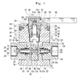
- Fig. 1 illustrates one embodiment of a trunnion ball valve for high pressure of the present invention
- Fig. 2 illustrates an exploded cross sectional view of Fig. 1 .
- a ball valve main unit (hereinafter referred to as valve main unit) 10 of the present invention includes a ball 12 serving as a ball, in a rotatable manner via a stem 11, and a seal mechanism 13 disposed on both sides of the ball 12 for providing seal contact with the ball 12, and has a configuration of a trunnion ball valve particularly suitable for flowing high-pressure fluid therein.
- the valve main unit 10 includes a body main unit 14.
- the body main unit 14 includes a body 15 and cap members 16, 16, which are provided on a primary side and a secondary side of the body 15, respectively.
- the ball 12 and the seal mechanism 13 are disposed inside the body main unit 14.
- High pressure in the present embodiment is for example 35 MPa or higher, and is assumed to be from 70 to 105 MPa, more specifically 90 MPa in piping facilities for a hydrogen station.
- the body 15 is formed in a substantially quadrangular shape.
- the cap members 16, 16 are screwed onto both sides of the body 15 via screwing sections 16a, respectively, in a state in which a gasket 17 is sandwiched between the body 15 and the cap members 16, 16.
- the cap members 16 have on its inner peripheral surface a mounting hole 19 for mounting the seat retainer 18, and the mounting hole 19 is opened so as to enable insertion of the seat retainer 18. Furthermore, the mounting hole 19 can mount a sealing member 20.
- the mounting hole 19 has a diameter expanded groove section 23 that has a diameter more expanded than that of the mounting hole 19, and a spacer 25 shaped in a substantially tubular shape is provided between the diameter expanded groove section 23 and a spring member 22 later described.
- the spring member 22 is provided in an elastic state between the spacer 25 and the seat retainer 18.
- an internal thread section 24 is formed in communication with the mounting hole 19.
- an external joint not illustrated can be screwed.
- the cap members 16 can be integrated with the body 15 by bonding means such as adhesion or welding.
- the ball 12 is made of stainless steel such as SUS316 as its base material.
- the ball 12 has a ball surface 12a, and the seat retainer 18 can be sealed onto the ball surface 12a.
- the ball 12 has a shaft section (upper shaft section) 12b at an upper part thereof and a trunnion (lower shaft section) 12c at a lower part thereof, and the ball 12 is made rotatable by applying the upper shaft section 12b and the lower shaft section 12c in an application hole 15a of the body 15.
- fluid flows while a communication hole 12d formed inside the ball 12 communicates with an inner flow channel 28 formed inside the seat retainer 18.
- the base material of the ball 12 is SUS316
- Vickers hardness is Hv200 or less.
- the ball 12 is a water contact part, so therefore it is preferable to use materials that do not become brittle by hydrogen.
- a pressure equalizing hole 12e is opened that communicates from the communication hole 12d to the upper surface of the ball. Through this pressure equalizing hole 12e, pressure within the cavity while the valve is opened can be released.
- the seal mechanism 13 is made up of the seat retainer 18, the spring member 22 and the sealing member 20.
- the seat retainer 18 is made of copper based alloy such as BeCu alloy (beryllium copper alloy) serving as base material thereof.
- BeCu alloy beryllium copper alloy
- a case in which, in particular, BeA-25 (beryllium copper) to which solution treatment, cold working and hardening treatment (heat treatment) are carried out is used as the base material of the seat retainer 18, sealing ability is exhibited as a result of containing a relatively soft copper component while the strength of stainless steel SUS630 or more is maintained.
- the Vickers hardness after carrying out the heat treatment is in a range of Hv 360 to 450
- mechanical property of beryllium copper is, for example, a tensile strength of 1200 to 1500 MPa, and 0.2% proof stress of 1000 to 1400 MPa.
- embrittlement caused by hydrogen will also be prevented.
- the sealing surface 18a which surface is a side to be in contact with the ball surface 12a.
- base material hardness of the seat retainer 18 is set higher than base material hardness of the ball 12, and satisfies the following relationship: "hardness of diamond-like carbon” > “base material hardness of seat retainer” > “base material hardness of ball”.
- the sealing ability is more maintained by use of BeCu for the seat retainer 18, as described above.
- the base material hardness of the ball can be set the same or higher than the base material hardness of the seat retainer.
- the seat retainer 18 is shaped to have a diameter expanded section 26 disposed so as to face the ball 12, and a tube section 27 having a smaller diameter than the diameter expanded section 26.
- the sealing surface 18a is provided on the diameter expanded section 26 on the surface facing the ball 12, and the sealing surface 18a and the ball surface 12a can be in contact in a sealing manner.
- the base material of the seat retainer 18 can be copper alloy such as aluminum bronze or material other than copper based alloy.
- BeCu alloy having high mechanical property is used in order to prevent deformation thereof, since the tube section of the seat retainer 18 that is a pressure resistant sliding component has a small diameter and a thin wall.
- Fig. 3 describes a case of providing the sealing surface 18a of the seat retainer 18.
- the drawing provides an X-axis from a spherical diameter center P of the ball surface 12a in a flow channel direction of the ball 12, and a Y-axis intersecting the X-axis.
- Two deviation points (offset point) Q, Q are provided in the Y-axis direction from the spherical diameter center P, having a predetermined distance H between the two points.
- Semispherical surfaces S, S having a radius R slightly longer than a radius R B of the ball surface 12a are drawn from the offset points Q, Q in opposite directions to the deviation (offset) sides by an angle of 180°, to structure the sealing surface 18a having a part of the semispherical surface S serve as a trajectory surface. That is to say, in Fig. 4 , the sealing surface 18a is a part of a trajectory of the slightly longer radius R of the ball surface 12a drawn from the offset points Q, Q of the predetermined distance H, and the sealing surface 18a is drawn based on the radius R.
- the predetermined distance H of the offset points Q is set so that a sealing position T on the sealing surface 18a with the ball surface 12a comes in a substantially center position of the sealing surface 18a.
- an inner flow channel diameter d N of the ball 12 is 10 mm and a spherical diameter D B of the ball surface 12a is ⁇ 20 mm (radius R B is 10 mm)
- the offset point Q having the distance H be ⁇ h is set as the slightly long radius R (radius R B + Ar), and the trajectory surface is drawn from this offset point Q.
- the predetermined distance H from the spherical diameter center P of the offset point Q can be changed as appropriate in accordance with the spherical diameter of the ball surface 12a. In the present embodiment, it is set so as to satisfy the following relationship: ⁇ r> ⁇ h.
- the sealing surface 18a of the seat retainer 18 is set as a slightly longer radius than the ball surface 12a without providing the offset point Q, the ball 12 comes in contact with an inner peripheral part of the sealing surface 18a of the seat retainer 18. This causes the inner peripheral part to locally contact the ball surface 12a, thereby increasing the possibility of damaging DLC. In order to avoid this, a technique of rounding the inner peripheral part to avoid the local contact can also be considered. This however causes the shift in position of the ball 12 in the X-axis direction, and would cause new problems such as the need of narrowing the shaft section at an upper part of the ball 12.
- the sealing position of the sealing surface 18a of the seat retainer18 with the ball surface 12a is made to be positioned substantially center of the sealing surface. Additionally, sealing is carried out by surface contact sealing the seat retainer 18 with the ball 12, by carrying out a finishing process to the ball 12 prior to processing DLC.
- the present invention has a sealing surface made to be in contact by line contact or surface contact.
- line contact in practice, the present invention forms a contacting sealing surface having a predetermined width.
- a width of a surface contact seal is a ring-shaped fitted part formed substantially parallel to the Y-axis, and for example has a width of approximately 0.5 mm. Since the trunnion ball valve of the present embodiment is for high pressure, the ball 12 changes in place due to the fluid pressure, however by setting the surface contact sealing width as described above, the ring-shaped fitted part is maintained. Furthermore, as illustrated in Fig. 4 , the sealing position T is set at a substantially center position of the sealing surface 12a. Therefore, even if the position of the sealing position T shifts slightly during use of the ball valve, the ring-shaped fitted state will be maintained.
- the sealing member 20 and back up rings 29 and 30 later described are arranged to the tube section 27 of the seat retainer 18.
- the tube section 27 is fitted into the mounting hole 19 of the cap members 16, to allow movement of the seat retainer 18 in the flow channel direction.
- the sealing member 20 is attached to an outer surface of the tube section 27 in an adhered state, and when the seat retainer 18 moves in the flow channel direction, the tube section 27 and the mounting hole 19 are sealed by the sealing member 20.
- an inner flow channel 28 in which high-pressure fluid flows is formed inside the seat retainer 18.
- a coating layer 31 made of diamond-like carbon is provided to at least both of the sealing surface 18a of the seat retainer 18 and the ball surface 12a that is in contact with the sealing surface 18a, to allow exhibition of sliding ability and sealing performance between the seat retainer 18 and the ball 12.
- a conforming layer 32 is provided on the coating layer 31 of one or both of the sealing surface 18a and/or the ball surface 12a.
- DLC is an amorphous hard film mainly made of hydrocarbon or an allotrope of carbon, has high hardness, and has excellent properties such as lubricity, wear and abrasion resistance, surface smoothness, and chemical stability. DLC can be deposited as a film by plasma CVD method or PVD method.
- source gas is made into a form of plasma inside a chamber with use of hydrocarbon gas such as acetylene, and vapor-phased hydrocarbon is deposited on the surface of the component.
- hydrocarbon gas such as acetylene
- vapor-phased hydrocarbon is deposited on the surface of the component.
- hydrogen is contained in the source, so therefore DLC will also contain hydrogen.
- examples include a sputtering technique and an ion plating technique.
- graphite that serves as the source is exposed to ion beams, arc discharge, glow discharge and the like under vacuum, and dispersed carbon atoms are adhered to the surface of the component.
- DLC is provided just using carbon, thereby allowing providing a DLC free of hydrogen.
- DLC of the present embodiment contains hydrogen, and thus DLC will not peel off from the base material.
- DLC process is carried out to the entire surface of the ball surface 12a for the ball 12, and to the thick lined parts illustrated in Fig. 3 for the seat retainer 18.
- the conforming layer 32 is provided if necessary in an appropriate thickness.
- a component on which the DLC coating layer 31 is provided is usable as a high surface pressure sliding component. Furthermore, by providing the conforming layer 32, initial comformability improves.
- the spring member 22 in the seal mechanism is constituted of, for example, a coil spring, and is provided between the diameter expanded section 26 of the seat retainer 18 fitted inside the mounting hole 19, and a spacer 25.
- the spring member 22 applies elastic force in the sealing surface 18a direction of the seat retainer 18.
- the spring member 22 may also be a disc spring.
- the sealing member 20 is constituted of, for example, a rubber O-ring, and is fitted into the mounting hole 19 together with the back up rings 29 and 30. As a result, the sealing member 20 is disposed between the mounting hole 19 on the body main unit 14 side and the outer surface 18a of the seat retainer 18.
- the back up ring 29 disposed on the sealing member 20 side is formed by, for example. PTFE (polytetrafluoroethylene), and the back up ring 30 disposed on the outside of the back up ring 29 is formed of, for example, PEEK (polyetheretherketone).
- Each of the sealing member 20 and the back up rings 29 and 30 may be made of material of different properties other than those described above, however even in those cases, it is preferable to use a soft material of a same degree as rubber or PTFE. By use of soft material, it is possible to change the shape of them, thereby making it easier to fit to the mounting hole 19.
- the sealing member 20 is fitted to the mounting hole 19 in a state in which the back up rings 29 and 30 are disposed on either sides. Both sides of the sealing member 20 are protected by the back up rings 29 and 30.
- valve main unit 10 is configured to seal high-pressure fluid by what is called a double sealing method, by the elastic force applied by the spring member 22 to the seat retainer 18 and an autofrettage force generated by exhibiting pressed force of the seal mechanism 13 by fluid pressure set in an inside diameter side of the sealing member 20.
- the outer peripheral side of the stem 11 has a lower packing washer 33, an inside diameter sealing member 34, an outer diameter sealing member 35, a thrust bearing 36, an upper packing washer 37 that can be fitted from an upper side of the lower packing washer 33, a gland 38 and a bush 39.
- the stem 11 is attached rotatable inside the body 15 via these members.
- the lower packing washer 33 includes a cylinder section 40 in which the inside diameter sealing member 34 that seals a space between the stem 11 is housed, and a bottom section 41 for mounting the inside diameter sealing member 34.
- a ring-shaped groove 42 is formed on an outer peripheral side of the cylinder section 40, and the outer diameter sealing member 35 is attached on the ring-shaped groove 42.
- the lower packing washer 33 is provided on an upper side of the stem 11 via the thrust bearing 36. This thus allow for the stem 11 to be rotatable with respect to the inside diameter sealing member 34 and the upper packing washer 37 via the thrust bearing 36.
- the gland 38 is formed in a substantially tubular shape, and includes a ring-shaped flange section 43 into which the upper packing washer 37 and the lower packing washer 33 can be fitted, and a lid section 45 that provides a lid for the upper packing washer 37 from above.
- the gland 38 is attached from the upper side of the upper packing washer 37 by screwing onto a mounting recess section 46 provided on the body 15, and houses the inside diameter sealing member 34.
- the upper and lower packing washers 37 and 33 on which the outer diameter sealing member 35 is attached is pressed in the direction of the thrust bearing 36.
- the gland 38 has the bush 39 attached on an inner peripheral side thereof, and the bush 39 causes the upper packing member 37 to be pressed against the lower packing washer 33.
- the bush 39 is provided made of material for example PEEK.
- the body 15 of the valve main unit 10 has a cover 50 attached, and via the cover 50, a handle cap 51 and a manual handle 52 are provided.
- the cover 50 is formed in a substantially disc shape, and has on its bottom surface side a flange-like side surface section 54 that can be fitted to a ring-shaped protrusion 53 formed on an upper surface side of the body 15.
- the side surface section 54 has two each of a counterbore section 55 and a notch 56 in intervals of 90°, provided in an alternate manner.
- the cover 50 has in its center section a hole 57 for inserting the handle cap 51.
- the hole 57 has a regulating piece (not illustrated) formed in a protruding manner, and this regulating piece regulates the rotation of the stem 11 to within a range of 90°.
- the handle cap 51 is formed in a substantially cylindrical shape with a substantially same diameter as the gland 38, and its outer peripheral side has a locking piece 59 in a protruding manner, which allows for locking with a regulating piece on the cover 50.
- the handle cap 51 has on its bottom side a fitting hole 51a that can fit the parallel section 11a formed on an upper end section of the stem 11.
- the handle cap 51 is integrated to the stem 11 by fitting the parallel section 11a into the fitting hole 51a.
- the handle cap 51 has an attachment hole 60, while an attached part of the handle 52 is provided to an outer diameter that can be fitted into the attachment hole 60.
- an internal thread 61 is provided thereon.
- the internal thread 61 allows for a secured bolt 62 and a locking screw (not illustrated) to be screwed thereon.
- the handle cap 51 is provided in a predetermined direction with respect to the stem 11 by fitting the parallel section 11a into the fitting hole 51a, and the cover 50 is fit and attached to the ring-shaped protrusion 53 from above the handle cap 51 in this state. Furthermore, the handle cap 51 is fixed by having the securing bolts 62 be screwed into the internal thread 61 via the counterbore section 55 of the cover 50 and the locking screw be screwed to the internal thread 61 via the notch 56 of the cover 50.
- the handle 52 is attached operable on an upper end side of the stem.
- the locking piece 59 is regulated by being in contact with the regulating piece. This enables opening and closing operation while regulating the rotation of the stem 11 to 90°.
- valve main unit 10 is provided as a manual valve.
- trunnion ball valve for high pressure of the present invention can be automated by use of an automatic operation actuator such as a pneumatic actuator as described later, other than attaching a manual handle as described above.
- the trunnion ball valve for high pressure of the present invention exhibits sliding ability and sealing performance by providing a coating layer 31 of diamond-like carbon to at least both of the sealing surface 18a of the seat retainer 18 and the ball surface 12a with which the sealing surface 18a is in contact. Accordingly, it is possible to maintain the sliding ability achieved by high surface pressure when high-pressure fluid such as high pressure hydrogen gas flows to prevent any damage on any sides of the seat retainer 18 and the ball 12, while securing low torque and sealing ability for improving operability while securely preventing leakage.
- the coating layer 31 having a DLC film thickness of 2 to 3 ⁇ m, it is possible to maintain ultraprecision machining of the base material such as sphericity and finished roughness even after the coating process.
- the sealing surface 18a is configured so that a part of a semispherical surface S drawn so as to have a radius R slightly longer than a radius R B of the ball surface 12a in an angle of 180° in a direction opposite to the offset side, from the offset point Q offset in a predetermined distance H in a Y-axis direction that intersects with an X-axis (in the flow channel direction of the ball 12 from the spherical diameter center P of the ball surface 12a), serve as a trajectory surface.
- the sealing position T on the sealing surface 18a with the ball surface 12a is made to be in a substantially center position of the sealing surface 12a, so as to prevent the ball surface 12a from being in contact with the sealing surface 18a in an inclined state to improve the sealing ability by pressure welding the ball surface 12a to the sealing surface 18a, thereby securely preventing leakage.
- the base material hardness of the seat retainer 18 is set higher than the base material hardness of the ball 12 to improve the durability of the seat retainer 18 and allowing for preventing any damage caused by galling due to rotation of the ball 12 and the like. As a result, high sealing ability is exhibited.
- the base material of the seat retainer 18 be BeCu alloy and the base material of the ball 12 be stainless steel, employment of such metal seat allows for reducing a given effect caused by temperature change of hydrogen, thereby improving durability. Even in a case in which the DLC coating layer 31 wears out, leakage can be avoided by a beryllium layer of the BeCu alloy, that is the base material of the seat retainer 18.
- the conforming layer 32 is provided on the surface of the coating layer 31 on either one or both of the sealing surface 18a and the ball surface 12a. This increases the conformability between the sealing surface 18a and the ball surface 12a, thereby preventing wearing due to abrasion while improving sliding ability. Furthermore, the degree of adhesion improves by the conforming layer 32, thereby improving the sealing ability.
- the valve main unit 10 of the present invention sets fluid pressure on the inside diameter side of the seat retainer 18 of the seal mechanism 13. Accordingly, it is possible to obtain the following autofrettage force.
- a left side of the seat retainer 18 is named a primary side and a right side thereof is named a secondary side.
- the following relationship is set, provided that an inside diameter ⁇ A is of the sealing surface 18a, an inside diameter cpD is of the sealing member 20, an outer diameter cpC is of the sealing surface 18a, and an outer diameter cpB is of the sealing member 20: inside diameter cpD ⁇ inside diameter ⁇ A ⁇ outer diameter ⁇ C ⁇ outer diameter ⁇ B. Therefore, regarding the autofrettage force on the primary side, the seat retainer 18 is pressed to the ball 12 by fluid pressure inside the flow channel applied on an area of inside diameter cpD - inside diameter ⁇ A while the valve is closed.
- the seat retainer 18 is pressed to the ball 12 by fluid pressure inside a cavity applied on an area of outer diameter cpC - inside diameter cpD.
- the trunnion ball valve for high pressure of the present invention can securely seal high-pressure fluid by exhibiting excellent self-sealing abilities attained by synergy of the double sealing method of the elastic force of the spring member 22 described above and the autofrettage force.
- Fig. 6 illustrates a second embodiment of a trunnion ball valve of the present invention
- Fig. 7 illustrates a main part of Fig. 6
- Fig. 8 illustrates a cross section of line A-A in Fig. 7 .
- the drawings illustrate a fitted state of the stem and the ball. It should be noted that in this embodiment, parts identical to the above embodiment are represented by identical reference signs, and explanations thereof are omitted.
- the trunnion ball valve for high pressure of this embodiment provides the ball 12 in an integrated manner with the upper shaft section 12b and the lower shaft section 12c as like the above embodiment, as illustrated in Fig. 7 .
- the ball 12 is disposed rotatable via radial bearings 110, 110 on an outer periphery of the upper shaft section 12b and the lower shaft section 12c.
- the radial bearings 110 are coated with a soft member 110b such as polytetrafluoroethylene (PTFE) on an inner surface of a rigid cylindrical body 110a such as stainless steel.
- PTFE polytetrafluoroethylene
- the upper shaft section 12b and the lower shaft section 12c of the ball 12 are supported by a pair of the cylindrical radial bearings 110, 110.
- the radial bearings 110 are set as a long shape that supports from the vicinity of a spherical section of the ball 12 to the vicinity of the stem connection section.
- the present embodiment is of a top-entry type structure in which the ball 12 is inserted from the upper section of the body 15, the present invention is applicable to a bottom-entry type in which the ball 12 is inserted from the lower section of the body 15.
- the stem 11 is joint to the upper shaft section 12b of the ball 12, and the ball 12 is provided rotatable through the rotational force of the stem.
- the stem 11 has a sliding surface 103 in a thrust direction, and a thrust bearing 105 is provided between the sliding surface 103 and the lower packing washer 33.
- the thrust bearing 105 is a member on which PTFE is coated on a rigid plate such as a thin stainless steel plate not illustrated.
- the sliding surface 103 and the lower packing washer 33 of the stem 11 are to be in contact with the PTFE.
- the stem 11 is made to be a bearing in the thrust direction via the thrust bearing 105.
- a parallel two-surface groove 102 is provided on a lower end of the stem 11.
- the parallel two-surface groove 102 is provided so as to be cut out in a direction on which load is received while the valve of the ball 12 is closed, that is to say, in a horizontal direction in Fig. 7 .
- a parallel two-surface section 101 that can be joint to the parallel two-surface groove 102 is provided on an upper end of the upper shaft section 12b of the ball 12.
- the stem 11 and the ball 12 are provided capable of operating together by the joint parallel two-surface groove 102 and parallel two-surface section 101.
- the thrust bearings 105 and the radial bearings 110 are determined in position and fixed, by being pushed from an upper side by the gland 38 screwed to the body 15. At this time, an upper side of the stem 11 is supported by the bush 39 for pressing, which bush is attached on the inner peripheral side of the gland 38, and the inside diameter sealing member 34 and outer diameter sealing member 35 are attached to their set positions.
- the recess and projecting relationship can be opposite, that is to say, the stem 11 may have the projecting parallel two-surface section and the ball 12 may have the recessed parallel two-surface groove.
- the trunnion ball valve for high pressure has, as illustrated in Fig. 6 and Fig. 9 , a pneumatic actuator 82 for automatic operation, on the stem upper end 11b.
- the trunnion ball valve for high pressure of the present invention can be a manually operated ball valve in which a handle 52 for manual operation is provided on the upper end 11b of the stem 11 as described above, or can be an automatically operated ball valve in which the upper end 11b of the stem 11 is connected to an automatically operating actuator 82 mounted on the body main unit 15.
- the actuator 82 is attached to the body main unit 15 via the cover 50.
- the actuator 82 allows for accurately controlling rotation of the ball 12 supported in a perpendicular state in the secondary direction, by a predetermined torque.
- the cover 50 is composed of a substrate 84 having an attachment opening 83, and a hanging plate 85.
- the substrate 84 has a bolt passage hole 86
- the hanging plate 85 has a position determination groove 87 and a counterbore hole 88 each opened at intervals of 90° in an alternate manner. Accordingly, the position determination groove 87 and the counterbore hole 88 are provided in two positions each with respect to the hanging plate 85.
- An outer periphery of an upper part of the shaft mounting section 80 of the body 15 in the ball valve main unit 10 has a notch provided in a ring shape, thereby forming a ring-shaped protrusion 90.
- On an outer surface of the ring-shaped protrusion 90 four internal thread sections 93 each in which a valve fixing bolt 91 and an attachment pin 92 can be screwed are provided at intervals of approximately 90°, at even positions.
- a housing groove 94 is provided on an upper surface of the ring-shaped protrusion 90, and the housing groove 94 is capable of housing a head 96 of an actuator fixing bolt 95 for fixing the actuator 82 to the cover 50.
- a ring-shaped protrusion 97 is formed that can be fitted into the attachment opening 83 opened on the cover 50, and on the bottom surface side of the actuator 82, an internal thread not illustrated is provided, which internal thread allows for screwing an actuator fixing bolt 95 therein.
- the actuator 82 is mounted on a predetermined position of the shaft mounting section 80 by locking the attachment pin 92 provided on an outer surface of an upper part of the shaft mounting section 80 to the position determination groove 87 to determine and fix its position, while fitting the ring-shaped protrusion 90 to the inner periphery of the hanging plate 85, and thereafter placing the cover 50 on the upper surface of the shaft mounting section 80.
- a projected section 122 formed on an upper end of the stem 11 is fitted to a recess section 121 formed on a lower edge of the output shaft 120 provided on the actuator 82, to connect the output shaft 120 with the stem 11.
- the head 96 of the actuator fixing bolt 95 is housed in a housing groove 94 on the upper surface of the shaft mounting section.
- valve fixing bolt 91 is screwed onto the internal thread section 93 from the hanging plate 85, to determine the position of and fix the cover 50 to the ball valve main unit 10, and via this cover 50, it is possible to accurately determine the position of and fix the actuator 82 to the predetermined position of the ball valve main unit 10. While the actuator 82 is operating, it is possible to accurately open and close the ball 12. It should be noted that the valve fixing bolt 91 can be provided at four positions, instead of the position determination pin.
- the actuator 82 is what is called a spring return type.
- a spring member 115 is provided inside, and a retainer member 116 is provided to prevent the springing out of the spring member 115.
- the retainer member 116 has a projecting striking section 117, and when a piston 118 provided inside reciprocates inside a cylinder 119, this striking section 117 comes into contact with both sides inside the cylinder 119. This regulates a stroke (not illustrated) of the piston 118, and regulates a rotational angle of the output shaft 120 to a predetermined angle, that is to say, to 90°.
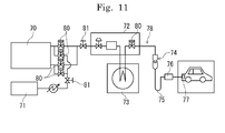
- Fig. 11 illustrates a hydrogen station in which a trunnion ball valve for high pressure of the present invention is provided.
- the hydrogen station includes an accumulator 70, a compressor 71, a dispenser 72, a precooling heat exchanger 73, a quick joint 74, a filling hose 75, a filling nozzle 76, and an in-vehicle tank 77, and these components constitute a system as a supply line 78 for high pressure hydrogen.
- the ball valve of the present invention has small pressure loss. Therefore the pressure loss of the entire system is reduced by providing the ball valve on a secondary side of the accumulator 70 or by providing the ball valve on other supply lines, and is suitable for a system illustrated in Fig. 10 .
- a manual valve 81 is provided on connection parts of each unit in the hydrogen station, and an automated valve 80 is appropriately provided on a primary or secondary side of each unit to control the opening and closing thereof.
- the accumulator 70 includes a plurality of separate tanks inside. By appropriately switching between valves 80 that connect the tanks with the compressor 71 and valves 80 that connect the tanks with the dispenser 72, hydrogen is supplied to the dispenser from a tank with a predetermined pressure, while tanks having a lower pressure than a predetermined low limit pressure are filled with hydrogen from the compressor 71 to achieve the predetermined pressure.
- the supply of hydrogen in the system is controlled by a predetermined program, and the supply of hydrogen is controlled as appropriate in accordance with a vehicle supplied amount.
- Fig. 10 is a longitudinal sectional view illustrating another embodiment of the trunnion ball valve for high pressure.
- Fig. 1 illustrates a top-entry type ball valve
- Fig. 10 illustrates a bottom-entry type ball valve.
- the ball valve configuration illustrated in Fig. 10 includes identical configurations as the configuration of the ball valve illustrated in Fig. 1 to Fig. 9 , and such identical parts are represented by identical reference signs and their explanations are omitted.
- the cap members 16, 16 are fixed by screwing onto the primary side and secondary side of a body 150, respectively, each via a screwing section 16a. Moreover, to an attachment hole 150a of the body 150, a ball having a stem 11, an upper shaft section 12b and a lower shaft section 12c is inserted from a bottom side of the body 150. The ball is fixed to a protrusion 203 of the body 150 via a screwing section 200 by use of a fixing screw 202 that has a fastening section 201, to configure a bottom-entry type ball valve.
- a packing 206 having a cross section of a substantially U-shape, a metal bush 205, a bearing 204, and radial bearings 110 (110a, 110b) are attached, and 207 in the drawing illustrates space.
- a hydrogen durability test was conducted to the ball 12 and the seat retainer 18 of the trunnion ball valve for high pressure of the present invention, and their durability were compared.
- the ball 12 was operated to open and close while high-pressure fluid whose heat cycle was at temperatures in a range of -40 °C to 85 °C was flown, under temperature of normal temperature, low temperature (-40 °C), and high temperature (85 °C). Hydrogen gas was used as the high-pressure fluid.
- the ball 12 was operated to open and close 40,000 times under the conditions. As a result, no abnormalities were found in either of the sliding ability or sealing performance. Although a pressure difference of 90 MPa occurred when high-pressure fluid was flown, an operation torque at this time was held down to for example 9.4 N ⁇ m, which is a rated pressure of the actuator. Accordingly, it can be said that high operability was maintained.
- the present invention is particularly used suitably in piping facilities such as a hydrogen station in which high-pressure fluid hydrogen and the like that is used in fuel cells flows, however the present invention can exhibit excellent sealing ability and torque for any pipeline through which high-pressure fluid flows.
- the present invention is suitable for a valve in a CNG (Compressed Natural Gas) station, or alternatively as a ball valve for high pressure that is used in various locations through which high-pressure fluid flows, such as a pipeline valve.
Landscapes
- Engineering & Computer Science (AREA)
- General Engineering & Computer Science (AREA)
- Mechanical Engineering (AREA)
- Taps Or Cocks (AREA)
- Fuel Cell (AREA)
Abstract
Description
- The present invention relates to a ball valve, in particular, a trunnion ball valve for high pressure suitable for use in a facility such as a hydrogen station in which high-pressure fluid such as hydrogen flows, and further relates to a hydrogen station.
- In recent years, together with the reviewing of energy policies, strong promotions have been made to spread supply infrastructure of hydrogen stations for fuel cell vehicles. In piping facilities in which high-pressure fluid flows such as a hydrogen station, for example, in a case of hydrogen, hydrogen reaches a high pressure of 80 MPa or more. Therefore, a valve for high-pressure fluid is used. As a valve for flowing such a high-pressure fluid, for example a needle valve disclosed in
Patent Document 1 is known. The needle valve has a structure in which a flow channel opens and closes by reciprocation movement of a needle. - Meanwhile, a trunnion ball valve may be used as a valve suitable for a case in which a flow channel is switched on or off while maintaining its flow. A known ball valve of this type is, for example, a trunnion ball valve of Patent Document 2. This trunnion ball valve is structured so that a ball made of metal is provided inside a body in a rotatable manner via a stem and a trunnion (lower stem), and a seat retainer is provided in which a ball seat for sealing is provided on both sides of the ball. Such a valve for high pressure requires maintaining high sealing performance to securely prevent leakage. Furthermore, in order to secure operability of the valve under high pressure, it is also necessary to satisfy sliding ability between the stem and the seat.
- One example of a trunnion ball valve for high pressure gas for improving sealing performance between the ball and the seat is a ball valve disclosed in
Patent Document 3. In order to improve the sealing performance between the ball and the seat under high pressure, this ball valve has diamond-like carbon deposited on the ball on a surface with which the seat is in contact. - Moreover, Patent Document 4 discloses a solenoid valve as a valve on which a film formed by diamond-like carbon is provided. The solenoid valve has a coating film formed on at least one sliding surface of an inner surface of a valve casing or an outer surface of a ball. Diamond-like carbon is used as the coating film, to improve the sliding ability.
-
- Patent Document 1: Japanese Translation of
PCT International Application Publication No. JP-T-2007-535648 - Patent Document 2: Japanese Unexamined Patent Application No.
2012-13141 - Patent Document 3: Japanese Unexamined Patent Application No.
2004-76884 - Patent Document 4: Japanese Unexamined Patent Application No.
2011-174569 - However, in a case of flowing hydrogen in a hydrogen station with use of a needle valve such as the one disclosed in
Patent Document 1, pressure loss caused by the high pressure of the hydrogen becomes great. As a result, a problem arises that it takes a long time to fill the station with hydrogen. - On the other hand, with a trunnion ball valve for high-pressure fluid, it is important to particularly improve both the sliding ability and the sealing performance between the ball and the seat. In this case, if resin material such as PEEK (polyetheretherketone) or PTFE (polytetrafluoroethylene) that are commonly used to secure sliding ability is used as the material for the seat in the ball valve of Patent Document 2, the sealing performance may not be secured due to easiness of the soft resin material in being damaged under high pressure. As such, in order to maintain sealing performance under high pressure, it is necessary to improve the hardness of a sealing section or a sealing surface, also in terms of durability.
-
Patent Document 3 attempts to maintain sealing ability (sealing performance) while high pressure gas is flown by improving durability, by depositing diamond-like carbon only to the contact surface of the ball with the seat. However, although the sealing ability of this ball valve is improved, sliding ability between the ball and the seat may drop due to the increase in adherence between the ball and the seat. - In a solenoid valve of Patent Document 4, the sliding ability is improved by forming a coating film of diamond-like carbon on a sliding surface of an inner surface of a valve casing and an outer surface of a ball. However, no disclosure nor suggestion is made as to this solenoid valve regarding improvement in the sealing performance of a valve seat.
- Furthermore, in the valve for high-pressure fluid, the ball is strongly pressed against a secondary side due to the high-pressure fluid. For example, in a case of applying a fluid pressure of 90 MPa, with a ball valve having a nominal diameter of 9/16 (port diameter of 6.4 mm), a load of approximately 1 t is applied to the ball. In this case, a stem is connected to the ball, and the stem is sealed by a packing. Therefore, when the ball is strongly pushed to the secondary side, the stem may also incline to the secondary side in a structure in which the ball and the stem are connected substantially as one. As a result, there is a fear that sealing ability by the packing is lost.
- Moreover, in a structure as in Patent Document 2 in which a columnar shaft is provided vertically to the ball, the ball is supported in a rotatable manner by a bearing (ball bearing) in which an outer periphery of the shaft is stacked. However, in a case in which a fluid with high pressure such as 90 MPa is supplied, the vicinity of a spherical part of the ball is most strongly pushed to the secondary side. As a result, the ball bearing disposed in the vicinity of the spherical part may break.
- The present invention was developed in order to solve the above issues, and an object thereof is to provide a trunnion ball valve for high pressure and a hydrogen station that is particularly suitable for high-pressure fluid, in which valve sliding ability between a ball and a valve seat is improved to realize a low torque during operation, while improving sealing performance to exhibit extremely high sealing ability and with improved durability so as to allow maintaining of the sealing ability for a long period of time.
- In order to obtain the aforementioned object, an invention according to
claim 1 is a trunnion ball valve for high pressure, comprising: a ball provided inside a body main unit in a freely rotatable manner; and a seal mechanism provided on positions on both sides of the ball so as to be in seal contact with the ball, the seal mechanism comprising: a seat retainer having a sealing surface that is to be in seal contact with a ball surface of the ball; a spring member provided for applying elastic force on the sealing surface side; and a sealing member provided on an outer surface of the seat retainer, at least both of the sealing surface of the seat retainer and the ball surface with which the sealing surface is to be in contact having a coating layer of diamond-like carbon provided thereon, so as to exhibit sliding ability and sealing performance.. - An invention according to claim 2 is a trunnion ball valve for high pressure wherein the sealing surface of the seat retainer is set at a position deviated from a spherical diameter center of the ball surface so as to have a slightly longer radius than a radius of the ball surface, and the sealing surface has a sealing position with the ball surface at a substantially center position of the sealing surface.
- An invention according to
claim 3 is a trunnion ball valve for high pressure wherein the sealing surface of the seat retainer has one part of a drawn semispherical surface serve as a trajectory surface, the semispherical surface drawn to have a slightly longer radius than that of the ball surface, the slightly longer radius being a length from a point deviated from a spherical diameter center of the ball surface along a Y-axis direction by a predetermined distance, at an angle 180° in a direction opposite to a side to which the point is deviated, the Y-axis running orthogonally to an X-axis that runs in a flow channel direction of the ball. - An invention according to claim 4 is a trunnion ball valve for high pressure wherein the seat retainer has a base material hardness set higher than a base material hardness of the ball.
- An invention according to claim 5 is a trunnion ball valve for high pressure wherein the base material of the seat retainer is BeCu alloy metal, and the base material of the ball is stainless steel.
- An invention according to claim 6 is a trunnion ball valve for high pressure wherein either one or both of the sealing surface and the ball surface has a conforming layer provided on a surface of the coating layer.
- An invention according to claim 7 is a trunnion ball valve for high pressure wherein the ball has an upper shaft section and a lower shaft section provided in an integrated manner, the ball being provided on an outer periphery of the upper and lower shaft section in a freely rotatable manner via a radial bearing, and the ball being provided in a freely rotatable manner via a rotational force of a stem that is joint to the shaft section, the stem having on a lower end thereof a parallel two-surface groove on which a parallel two-surface section provided on an upper end of the shaft section is provided to work in connection therewith, and when the ball is pressed by high-pressure fluid while the valve is closed, the ball having the upper and lower shaft sections is supported in a perpendicular state in the secondary direction.
- An invention according to claim 8 is a trunnion ball valve for high pressure wherein the radial bearing is a member in which an inner peripheral surface of a rigid cylindrical body is coated with polytetrafluoroethylene.
- An invention according to claim 9 is a trunnion ball valve for high pressure wherein the trunnion ball valve is a manually operated ball valve to which a handle for manual operation is provided on the upper end of the stem, or is an automatically operated ball valve in which the upper end of the stem is connected to an actuator installed in the body main unit for automated operation.
- An invention according to
claim 10 is a hydrogen station comprising a trunnion ball valve for high pressure in a supply line for high pressure hydrogen. - According to the invention of
claim 1, it is possible to provide a ball valve of a trunnion type structure suitable for high-pressure fluid in particular. By providing a coating layer of diamond-like carbon to at least both of a sealing surface of a seat retainer and a ball surface, sliding ability of a valve element with a valve seat is improved, to realize a low torque during operation, while also improving sealing performance to exert extremely high sealing ability thereby improving durability that allows maintaining of the sealing ability for a long period of time. Further, the valve element can be operated under high pressure while possessing both these properties. As a result, even if a spring constant of the spring member is reduced, it is possible to easily operate the valve element manually with excellent operability, while securely preventing leakage of the high-pressure fluid by autofrettage force caused by the ball valve in the trunnion structure for high-pressure fluid. - According to the invention of
claim 2 or 3, it is possible to seal by making the ball surface and the sealing surface be in contact with each other by line contact or surface contact that tolerates to amplitude. This allows for improving low torque while securely maintaining sealing performance between the ball surface and the sealing surface in a minimum contact area required. Furthermore, by sealing the sealing surface with the ball surface at a position center of the sealing surface, the ball surface can pressure weld to the sealing surface in a pressure equalized state, which state improves the sealing ability and allows for securely preventing leakage. - According to the invention of claim 4, durability is improved by maintaining the diamond-like carbon layer, particularly by the increase in hardness of the seat retainer, and even in a case in which the seat retainer is of a thin-wall tubular shape, any damage thereto is prevented, thereby maintaining a high sealing ability. Furthermore, even in the unlikely event that the diamond-like carbon wears out, a minimum degree of sliding ability is secured by difference in hardness between base materials. As a result, the sealing ability can be maintained for a long period of time, and durability is improved. As such, by providing a seat retainer having high hardness under the diamond-like carbon coating layer, fail safe function is exhibited and leakage of high pressure hydrogen is securely prevented.
- According to the invention of claim 5, by having the base material of the seat retainer be made of BeCu alloy that is made of copper based alloy, durability against hydrogen is improved. Improvement in strength of the seat retainer contributes to integrity of the diamond-like carbon, thereby improving both of the sliding ability and the sealing performance. Furthermore, by setting the difference in hardness between the seat retainer and the base material into an optimum state, even in the event that the diamond-like carbon coating layer supposedly wears out, leakage is prevented by a beryllium layer of the seat retainer. In addition, since the seat retainer is made of copper alloy, galling of the seat retainer by the ball is prevented, thereby avoiding malfunctioning.
- According to the invention of claim 6, by providing a conforming layer on a surface of the coating layer provided on at least one or both of the sealing surface and the ball surface, conformability between the sealing surface and the ball surface is improved to prevent wearing caused by abrasion, and allows for improving sliding ability. Since the conforming layer improves adhesion, the sealing ability also improves.
- According to the invention of claim 7, a constant position of an inside diameter sealing member, which member is a packing for the stem sealing, is securely maintained, thereby exhibiting sealing functions effectively. That is to say, the ball having the upper and lower shaft sections is made to be supported in a secondary direction in a perpendicular state. Therefore, the ball is capable of moving slightly parallel along a flow channel direction, along a parallel two-surface groove. This allows for securely preventing a slight parallel movement when a high pressure is applied while the valve is closed, thereby causing load to be received by the ball in the flow channel direction. Alternatively, it is possible to securely prevent an inclination phenomenon in a case in which the ball is deformed due to receiving the high load. Therefore, it is possible to maintain durability and torque even in a case in which rotational operation of the ball is repeatedly carried out, thereby maintaining high sealing ability of the stem with use of the inside diameter sealing member.
- According to the invention of claim 8, even in a case in which excess force is applied to the ball in a radial direction by the high-pressure fluid, torque is maintained by the radial bearing. Further, even in a case in which rotational operation is repeatedly carried out, sliding resistance is small and the sliding ability is further improved by soft polytetrafluoroethylene. This improves the durability of the ball and prevents deterioration thereof.
- According to the invention of claim 9, it is possible to rotatably operate the ball by manual operation or automated operation, and can be established by selecting appropriate operations in accordance with use conditions such as a pressure and type of high-pressure fluid, location to be established and the like.
- According to the invention of
claim 10, a hydrogen station includes a trunnion ball valve for high pressure that realizes low torque during operation, which ball valve exhibits extremely high sealing ability by improving sealing performance and can improve durability that allows for maintaining sealing ability for a long period of time, and the hydrogen station can be operated under high pressure while maintaining both these properties. Accordingly, it is possible to securely prevent leakage of high-pressure fluid by exhibition of autofrettage force due to the ball valve, and by easy valve element operation automatically or manually attained by the excellent operability, flow channel is switched, thereby allowing supplying of a predetermined amount of hydrogen or stopping the supply of hydrogen. In particular, it is possible to significantly reduce frequency of carrying out maintenance to the hydrogen station. -
-
Fig. 1 is a longitudinal sectional view illustrating one embodiment of a trunnion ball valve for high pressure of the present invention. -
Fig. 2 is an exploded cross sectional view of the trunnion ball valve for high pressure illustrated inFig. 1 . -
Fig. 3 is a longitudinal sectional view of a seat retainer. -
Fig. 4 is an exploded view of a main part illustrating a sealed state of a ball with a seat retainer. -
Fig. 5 is an enlarged cross sectional view of one part ofFig. 1 . -
Fig. 6 is a longitudinal sectional view illustrating another embodiment of a trunnion ball valve for high pressure of the present invention. -
Fig. 7 is an enlarged cross sectional view of a main part illustrating a closed state of the trunnion ball valve for high pressure illustrated inFig. 6 . -
Fig. 8 is an enlarged cross sectional view taken along line A-A ofFig. 7 . -
Fig. 9 is an exploded perspective view illustrating the ball valve and actuator illustrated inFig. 6 . -
Fig. 10 is a longitudinal sectional view illustrating another embodiment of a trunnion ball valve for high pressure of the present invention. -
Fig. 11 is a block diagram illustrating a hydrogen station. - Described in detail below is an embodiment of a trunnion ball valve for high pressure of the present invention, with reference to drawings.
Fig. 1 illustrates one embodiment of a trunnion ball valve for high pressure of the present invention, andFig. 2 illustrates an exploded cross sectional view ofFig. 1 . - As illustrated in
Fig. 1 andFig. 2 , a ball valve main unit (hereinafter referred to as valve main unit) 10 of the present invention includes aball 12 serving as a ball, in a rotatable manner via astem 11, and aseal mechanism 13 disposed on both sides of theball 12 for providing seal contact with theball 12, and has a configuration of a trunnion ball valve particularly suitable for flowing high-pressure fluid therein. - The valve
main unit 10 includes a bodymain unit 14. The bodymain unit 14 includes abody 15 andcap members body 15, respectively. Theball 12 and theseal mechanism 13 are disposed inside the bodymain unit 14. High pressure in the present embodiment is for example 35 MPa or higher, and is assumed to be from 70 to 105 MPa, more specifically 90 MPa in piping facilities for a hydrogen station. - The
body 15 is formed in a substantially quadrangular shape. Thecap members body 15 via screwingsections 16a, respectively, in a state in which agasket 17 is sandwiched between thebody 15 and thecap members main unit 14. Thecap members 16 have on its inner peripheral surface a mountinghole 19 for mounting theseat retainer 18, and the mountinghole 19 is opened so as to enable insertion of theseat retainer 18. Furthermore, the mountinghole 19 can mount a sealingmember 20. - Moreover, the mounting
hole 19 has a diameter expandedgroove section 23 that has a diameter more expanded than that of the mountinghole 19, and aspacer 25 shaped in a substantially tubular shape is provided between the diameter expandedgroove section 23 and aspring member 22 later described. Thespring member 22 is provided in an elastic state between thespacer 25 and theseat retainer 18. On the other side of the mountinghole 19, aninternal thread section 24 is formed in communication with the mountinghole 19. Into theinternal thread section 24, an external joint not illustrated can be screwed. It should be noted that thecap members 16 can be integrated with thebody 15 by bonding means such as adhesion or welding. - The
ball 12 is made of stainless steel such as SUS316 as its base material. Theball 12 has aball surface 12a, and theseat retainer 18 can be sealed onto theball surface 12a. Theball 12 has a shaft section (upper shaft section) 12b at an upper part thereof and a trunnion (lower shaft section) 12c at a lower part thereof, and theball 12 is made rotatable by applying theupper shaft section 12b and thelower shaft section 12c in anapplication hole 15a of thebody 15. In a case in which theball 12 is operated in a rotating manner by thestem 11, fluid flows while acommunication hole 12d formed inside theball 12 communicates with aninner flow channel 28 formed inside theseat retainer 18. In a case in which the base material of theball 12 is SUS316, Vickers hardness is Hv200 or less. In a case in which theball 12 is made of stainless steel, theball 12 is a water contact part, so therefore it is preferable to use materials that do not become brittle by hydrogen. - Inside the
upper shaft section 12b of theball 12, apressure equalizing hole 12e is opened that communicates from thecommunication hole 12d to the upper surface of the ball. Through thispressure equalizing hole 12e, pressure within the cavity while the valve is opened can be released. - The
seal mechanism 13 is made up of theseat retainer 18, thespring member 22 and the sealingmember 20. - The
seat retainer 18 is made of copper based alloy such as BeCu alloy (beryllium copper alloy) serving as base material thereof. In a case in which, in particular, BeA-25 (beryllium copper) to which solution treatment, cold working and hardening treatment (heat treatment) are carried out is used as the base material of theseat retainer 18, sealing ability is exhibited as a result of containing a relatively soft copper component while the strength of stainless steel SUS630 or more is maintained. In the case in which the base material of theseat retainer 18 is beryllium copper, the Vickers hardness after carrying out the heat treatment is in a range of Hv 360 to 450, and mechanical property of beryllium copper is, for example, a tensile strength of 1200 to 1500 MPa, and 0.2% proof stress of 1000 to 1400 MPa. In the case in which the seat retainer is made of copper based alloy, embrittlement caused by hydrogen will also be prevented. - When forming the
seat retainer 18, it is preferable to polish the sealingsurface 18a, which surface is a side to be in contact with theball surface 12a. - In the present embodiment, base material hardness of the
seat retainer 18 is set higher than base material hardness of theball 12, and satisfies the following relationship: "hardness of diamond-like carbon" > "base material hardness of seat retainer" > "base material hardness of ball". Accordingly, even if diamond-like carbon (DLC) later described is worn, the difference in hardness between DLC of theball surface 12a and the base material of theseat retainer 18, or alternatively, in the event of exhaustion of DLC of theball surface 12a, the difference in hardness between the base material of the ball and the base material of the seat retainer allows for maintaining a minimum required sliding ability without occurrence of what is called "galling", thereby obtaining a durable ball valve capable of maintaining sealing ability for a long period of time. In the present embodiment, the sealing ability is more maintained by use of BeCu for theseat retainer 18, as described above. That is to say, with the double or triple settings of providing DLC, providing a difference in hardness between the base material of theseat retainer 18 and that of the base material of theball 12, and having the base material of theseat retainer 18 be BeCu alloy, fail safe measures are taken so that high pressure hydrogen does not leak. - It should be noted that depending on its purpose, the base material hardness of the ball can be set the same or higher than the base material hardness of the seat retainer.
- Specifically, the
seat retainer 18 is shaped to have a diameter expandedsection 26 disposed so as to face theball 12, and atube section 27 having a smaller diameter than the diameter expandedsection 26. As described above, the sealingsurface 18a is provided on the diameter expandedsection 26 on the surface facing theball 12, and the sealingsurface 18a and theball surface 12a can be in contact in a sealing manner. As long as theseat retainer 18 can exhibit the function as a sliding component, the base material of theseat retainer 18 can be copper alloy such as aluminum bronze or material other than copper based alloy. In the present embodiment, BeCu alloy having high mechanical property is used in order to prevent deformation thereof, since the tube section of theseat retainer 18 that is a pressure resistant sliding component has a small diameter and a thin wall. -
Fig. 3 describes a case of providing the sealingsurface 18a of theseat retainer 18. The drawing provides an X-axis from a spherical diameter center P of theball surface 12a in a flow channel direction of theball 12, and a Y-axis intersecting the X-axis. Two deviation points (offset point) Q, Q are provided in the Y-axis direction from the spherical diameter center P, having a predetermined distance H between the two points. Semispherical surfaces S, S having a radius R slightly longer than a radius RB of theball surface 12a are drawn from the offset points Q, Q in opposite directions to the deviation (offset) sides by an angle of 180°, to structure the sealingsurface 18a having a part of the semispherical surface S serve as a trajectory surface. That is to say, inFig. 4 , the sealingsurface 18a is a part of a trajectory of the slightly longer radius R of theball surface 12a drawn from the offset points Q, Q of the predetermined distance H, and the sealingsurface 18a is drawn based on the radius R. - At this time, the predetermined distance H of the offset points Q is set so that a sealing position T on the sealing
surface 18a with theball surface 12a comes in a substantially center position of the sealingsurface 18a. As one example, in a case in which, inFig. 1 , an inner flow channel diameter dN of theball 12 is 10 mm and a spherical diameter DB of theball surface 12a is ϕ20 mm (radius RB is 10 mm), the offset point Q having the distance H be Δh is set as the slightly long radius R (radius RB + Ar), and the trajectory surface is drawn from this offset point Q. The predetermined distance H from the spherical diameter center P of the offset point Q can be changed as appropriate in accordance with the spherical diameter of theball surface 12a. In the present embodiment, it is set so as to satisfy the following relationship: Δr>Δh. - If supposedly the sealing
surface 18a of theseat retainer 18 is set as a slightly longer radius than theball surface 12a without providing the offset point Q, theball 12 comes in contact with an inner peripheral part of the sealingsurface 18a of theseat retainer 18. This causes the inner peripheral part to locally contact theball surface 12a, thereby increasing the possibility of damaging DLC. In order to avoid this, a technique of rounding the inner peripheral part to avoid the local contact can also be considered. This however causes the shift in position of theball 12 in the X-axis direction, and would cause new problems such as the need of narrowing the shaft section at an upper part of theball 12. - In the present embodiment, by providing the offset point Q, the sealing position of the sealing
surface 18a of the seat retainer18 with theball surface 12a is made to be positioned substantially center of the sealing surface. Additionally, sealing is carried out by surface contact sealing theseat retainer 18 with theball 12, by carrying out a finishing process to theball 12 prior to processing DLC. - The present invention has a sealing surface made to be in contact by line contact or surface contact. Although it is worded as line contact, in practice, the present invention forms a contacting sealing surface having a predetermined width. For example, a width of a surface contact seal is a ring-shaped fitted part formed substantially parallel to the Y-axis, and for example has a width of approximately 0.5 mm. Since the trunnion ball valve of the present embodiment is for high pressure, the
ball 12 changes in place due to the fluid pressure, however by setting the surface contact sealing width as described above, the ring-shaped fitted part is maintained. Furthermore, as illustrated inFig. 4 , the sealing position T is set at a substantially center position of the sealingsurface 12a. Therefore, even if the position of the sealing position T shifts slightly during use of the ball valve, the ring-shaped fitted state will be maintained. - The sealing
member 20 and back up rings 29 and 30 later described are arranged to thetube section 27 of theseat retainer 18. Thetube section 27 is fitted into the mountinghole 19 of thecap members 16, to allow movement of theseat retainer 18 in the flow channel direction. The sealingmember 20 is attached to an outer surface of thetube section 27 in an adhered state, and when theseat retainer 18 moves in the flow channel direction, thetube section 27 and the mountinghole 19 are sealed by the sealingmember 20. Moreover, inside theseat retainer 18, aninner flow channel 28 in which high-pressure fluid flows is formed. - In an event of configuring a sealing part of the
seat retainer 18 with theball 12, acoating layer 31 made of diamond-like carbon is provided to at least both of the sealingsurface 18a of theseat retainer 18 and theball surface 12a that is in contact with the sealingsurface 18a, to allow exhibition of sliding ability and sealing performance between theseat retainer 18 and theball 12. - In this case, a conforming
layer 32 is provided on thecoating layer 31 of one or both of the sealingsurface 18a and/or theball surface 12a. - DLC is an amorphous hard film mainly made of hydrocarbon or an allotrope of carbon, has high hardness, and has excellent properties such as lubricity, wear and abrasion resistance, surface smoothness, and chemical stability. DLC can be deposited as a film by plasma CVD method or PVD method.
- In a case in which DLC is provided by the plasma CVD method, source gas is made into a form of plasma inside a chamber with use of hydrocarbon gas such as acetylene, and vapor-phased hydrocarbon is deposited on the surface of the component. In this case, hydrogen is contained in the source, so therefore DLC will also contain hydrogen.
- On the other hand, in a case in which DLC is provided by the PVD method, examples include a sputtering technique and an ion plating technique. In this case, graphite that serves as the source is exposed to ion beams, arc discharge, glow discharge and the like under vacuum, and dispersed carbon atoms are adhered to the surface of the component. In this method, DLC is provided just using carbon, thereby allowing providing a DLC free of hydrogen.
- In a case in which hydrogen being a high-pressure fluid flows through the flow channel of the ball valve, there may be cases in which the hydrogen fluid infiltrates inside DLC of the
coating layer 31. However, DLC of the present embodiment contains hydrogen, and thus DLC will not peel off from the base material. - In the case of providing DLC, DLC process is carried out to the entire surface of the
ball surface 12a for theball 12, and to the thick lined parts illustrated inFig. 3 for theseat retainer 18. In this case, it is preferable to have a sufficiently high Vickers hardness as compared to the base material of the seat retainer and ball, for example in a range of HV 1500 to 3000, and DLC is to be provided with uniform thickness on a processing surface so as to have a film thickness of 2 to 3 µm. The conforminglayer 32 is provided if necessary in an appropriate thickness. - A component on which the
DLC coating layer 31 is provided is usable as a high surface pressure sliding component. Furthermore, by providing the conforminglayer 32, initial comformability improves. - The
spring member 22 in the seal mechanism is constituted of, for example, a coil spring, and is provided between the diameter expandedsection 26 of theseat retainer 18 fitted inside the mountinghole 19, and aspacer 25. Thespring member 22 applies elastic force in the sealingsurface 18a direction of theseat retainer 18. Thespring member 22 may also be a disc spring. - The sealing
member 20 is constituted of, for example, a rubber O-ring, and is fitted into the mountinghole 19 together with the back up rings 29 and 30. As a result, the sealingmember 20 is disposed between the mountinghole 19 on the bodymain unit 14 side and theouter surface 18a of theseat retainer 18. The back upring 29 disposed on the sealingmember 20 side is formed by, for example. PTFE (polytetrafluoroethylene), and the back upring 30 disposed on the outside of the back upring 29 is formed of, for example, PEEK (polyetheretherketone). - Each of the sealing
member 20 and the back up rings 29 and 30 may be made of material of different properties other than those described above, however even in those cases, it is preferable to use a soft material of a same degree as rubber or PTFE. By use of soft material, it is possible to change the shape of them, thereby making it easier to fit to the mountinghole 19. The sealingmember 20 is fitted to the mountinghole 19 in a state in which the back up rings 29 and 30 are disposed on either sides. Both sides of the sealingmember 20 are protected by the back up rings 29 and 30. - Due to the sealing function by the
ball 12 and theseal mechanism 13, the valvemain unit 10 is configured to seal high-pressure fluid by what is called a double sealing method, by the elastic force applied by thespring member 22 to theseat retainer 18 and an autofrettage force generated by exhibiting pressed force of theseal mechanism 13 by fluid pressure set in an inside diameter side of the sealingmember 20. - The outer peripheral side of the
stem 11 has alower packing washer 33, an insidediameter sealing member 34, an outerdiameter sealing member 35, athrust bearing 36, anupper packing washer 37 that can be fitted from an upper side of thelower packing washer 33, agland 38 and abush 39. Thestem 11 is attached rotatable inside thebody 15 via these members. - The
lower packing washer 33 includes acylinder section 40 in which the insidediameter sealing member 34 that seals a space between thestem 11 is housed, and abottom section 41 for mounting the insidediameter sealing member 34. A ring-shapedgroove 42 is formed on an outer peripheral side of thecylinder section 40, and the outerdiameter sealing member 35 is attached on the ring-shapedgroove 42. As such, by having the insidediameter sealing member 34 be provided between thestem 11 and thelower packing washer 33, and the outerdiameter sealing member 35 be provided between thelower packing washer 33 and thebody 15, leakage of the high-pressure fluid from the shaft-provided part of thestem 11 is prevented. - The
lower packing washer 33 is provided on an upper side of thestem 11 via thethrust bearing 36. This thus allow for thestem 11 to be rotatable with respect to the insidediameter sealing member 34 and theupper packing washer 37 via thethrust bearing 36. - The
gland 38 is formed in a substantially tubular shape, and includes a ring-shapedflange section 43 into which theupper packing washer 37 and thelower packing washer 33 can be fitted, and alid section 45 that provides a lid for theupper packing washer 37 from above. Thegland 38 is attached from the upper side of theupper packing washer 37 by screwing onto a mountingrecess section 46 provided on thebody 15, and houses the insidediameter sealing member 34. The upper andlower packing washers diameter sealing member 35 is attached is pressed in the direction of thethrust bearing 36. Thegland 38 has thebush 39 attached on an inner peripheral side thereof, and thebush 39 causes theupper packing member 37 to be pressed against thelower packing washer 33. Thebush 39 is provided made of material for example PEEK. - With such a configuration, even in a case in which high-pressure fluid flows inside the valve
main unit 10 and force in a direction in which thestem 11 rises is applied due to the difference in pressure with the outer air, the insidediameter sealing member 34 is protected by the upper andlower packing washers diameter sealing member 34 is prevented from being crushed in the shaft direction, thereby preventing a decrease in sealing ability and securely preventing the leakage of high-pressure fluid. Therefore, it is further possible to prevent the wearing out of the insidediameter sealing member 34 and reduce the decrease in operability of thestem 11. - Moreover, the
body 15 of the valvemain unit 10 has acover 50 attached, and via thecover 50, ahandle cap 51 and amanual handle 52 are provided. - The
cover 50 is formed in a substantially disc shape, and has on its bottom surface side a flange-likeside surface section 54 that can be fitted to a ring-shapedprotrusion 53 formed on an upper surface side of thebody 15. Theside surface section 54 has two each of acounterbore section 55 and anotch 56 in intervals of 90°, provided in an alternate manner. Thecover 50 has in its center section ahole 57 for inserting thehandle cap 51. Thehole 57 has a regulating piece (not illustrated) formed in a protruding manner, and this regulating piece regulates the rotation of thestem 11 to within a range of 90°. - The
handle cap 51 is formed in a substantially cylindrical shape with a substantially same diameter as thegland 38, and its outer peripheral side has alocking piece 59 in a protruding manner, which allows for locking with a regulating piece on thecover 50. Thehandle cap 51 has on its bottom side afitting hole 51a that can fit theparallel section 11a formed on an upper end section of thestem 11. Thehandle cap 51 is integrated to thestem 11 by fitting theparallel section 11a into thefitting hole 51a. Moreover, thehandle cap 51 has anattachment hole 60, while an attached part of thehandle 52 is provided to an outer diameter that can be fitted into theattachment hole 60. - It should be noted that at the positions corresponding to the
counterbore section 55 and thenotch 56 on the side surface of the ring-shapedprotrusion 53 of thebody 15, aninternal thread 61 is provided thereon. Theinternal thread 61 allows for asecured bolt 62 and a locking screw (not illustrated) to be screwed thereon. - The
handle cap 51 is provided in a predetermined direction with respect to thestem 11 by fitting theparallel section 11a into thefitting hole 51a, and thecover 50 is fit and attached to the ring-shapedprotrusion 53 from above thehandle cap 51 in this state. Furthermore, thehandle cap 51 is fixed by having the securingbolts 62 be screwed into theinternal thread 61 via thecounterbore section 55 of thecover 50 and the locking screw be screwed to theinternal thread 61 via thenotch 56 of thecover 50. By fitting thehandle 52 into theattachment hole 60 of thehandle cap 51 and fixing thehandle 52 with a fixingbolt 64, thehandle 52 is attached operable on an upper end side of the stem. During rotational operation of thehandle 52, the lockingpiece 59 is regulated by being in contact with the regulating piece. This enables opening and closing operation while regulating the rotation of thestem 11 to 90°. - As such, by attaching a
manual handle 52 to the upper end side of the stem, the valvemain unit 10 is provided as a manual valve. - It should be noted that the trunnion ball valve for high pressure of the present invention can be automated by use of an automatic operation actuator such as a pneumatic actuator as described later, other than attaching a manual handle as described above.
- Next described is an effect of a trunnion ball valve for high pressure of the present invention in the above embodiment.
- The trunnion ball valve for high pressure of the present invention exhibits sliding ability and sealing performance by providing a
coating layer 31 of diamond-like carbon to at least both of the sealingsurface 18a of theseat retainer 18 and theball surface 12a with which thesealing surface 18a is in contact. Accordingly, it is possible to maintain the sliding ability achieved by high surface pressure when high-pressure fluid such as high pressure hydrogen gas flows to prevent any damage on any sides of theseat retainer 18 and theball 12, while securing low torque and sealing ability for improving operability while securely preventing leakage. By providing thecoating layer 31 having a DLC film thickness of 2 to 3 µm, it is possible to maintain ultraprecision machining of the base material such as sphericity and finished roughness even after the coating process. - The sealing
surface 18a is configured so that a part of a semispherical surface S drawn so as to have a radius R slightly longer than a radius RB of theball surface 12a in an angle of 180° in a direction opposite to the offset side, from the offset point Q offset in a predetermined distance H in a Y-axis direction that intersects with an X-axis (in the flow channel direction of theball 12 from the spherical diameter center P of theball surface 12a), serve as a trajectory surface. Therefore, the sealing position T on the sealingsurface 18a with theball surface 12a is made to be in a substantially center position of the sealingsurface 12a, so as to prevent theball surface 12a from being in contact with the sealingsurface 18a in an inclined state to improve the sealing ability by pressure welding theball surface 12a to the sealingsurface 18a, thereby securely preventing leakage. - Even in a case in which DLC wears out, the base material hardness of the
seat retainer 18 is set higher than the base material hardness of theball 12 to improve the durability of theseat retainer 18 and allowing for preventing any damage caused by galling due to rotation of theball 12 and the like. As a result, high sealing ability is exhibited. - Furthermore, by making the base material of the
seat retainer 18 be BeCu alloy and the base material of theball 12 be stainless steel, employment of such metal seat allows for reducing a given effect caused by temperature change of hydrogen, thereby improving durability. Even in a case in which theDLC coating layer 31 wears out, leakage can be avoided by a beryllium layer of the BeCu alloy, that is the base material of theseat retainer 18. - The conforming
layer 32 is provided on the surface of thecoating layer 31 on either one or both of the sealingsurface 18a and theball surface 12a. This increases the conformability between the sealingsurface 18a and theball surface 12a, thereby preventing wearing due to abrasion while improving sliding ability. Furthermore, the degree of adhesion improves by the conforminglayer 32, thereby improving the sealing ability. - The valve
main unit 10 of the present invention sets fluid pressure on the inside diameter side of theseat retainer 18 of theseal mechanism 13. Accordingly, it is possible to obtain the following autofrettage force. - In
Fig. 1 andFig. 5 , suppose that a left side of theseat retainer 18 is named a primary side and a right side thereof is named a secondary side. In this case, at a time in which fluid flows from the primary side to the secondary side as illustrated by the arrows inFig. 1 , the following relationship is set, provided that an inside diameter ϕA is of the sealingsurface 18a, an inside diameter cpD is of the sealingmember 20, an outer diameter cpC is of the sealingsurface 18a, and an outer diameter cpB is of the sealing member 20: inside diameter cpD < inside diameter ϕA < outer diameter ϕC < outer diameter ϕB. Therefore, regarding the autofrettage force on the primary side, theseat retainer 18 is pressed to theball 12 by fluid pressure inside the flow channel applied on an area of inside diameter cpD - inside diameter ϕA while the valve is closed. - On the other hand, regarding the autofrettage force on the secondary side, the
seat retainer 18 is pressed to theball 12 by fluid pressure inside a cavity applied on an area of outer diameter cpC - inside diameter cpD. - As from the above, the trunnion ball valve for high pressure of the present invention can securely seal high-pressure fluid by exhibiting excellent self-sealing abilities attained by synergy of the double sealing method of the elastic force of the
spring member 22 described above and the autofrettage force. -
Fig. 6 illustrates a second embodiment of a trunnion ball valve of the present invention,Fig. 7 illustrates a main part ofFig. 6 , andFig. 8 illustrates a cross section of line A-A inFig. 7 . The drawings illustrate a fitted state of the stem and the ball. It should be noted that in this embodiment, parts identical to the above embodiment are represented by identical reference signs, and explanations thereof are omitted. - The trunnion ball valve for high pressure of this embodiment provides the
ball 12 in an integrated manner with theupper shaft section 12b and thelower shaft section 12c as like the above embodiment, as illustrated inFig. 7 . Theball 12 is disposed rotatable viaradial bearings upper shaft section 12b and thelower shaft section 12c. - As illustrated in
Fig. 7 , theradial bearings 110 are coated with asoft member 110b such as polytetrafluoroethylene (PTFE) on an inner surface of a rigidcylindrical body 110a such as stainless steel. By supporting theball 12 with theradial bearings 110 as such, torque can be maintained and durability can be improved even if a large force is applied to theball 12 in a radial direction by the high-pressure fluid. In this case, theupper shaft section 12b and thelower shaft section 12c of theball 12 are supported by a pair of the cylindricalradial bearings radial bearings 110 are set as a long shape that supports from the vicinity of a spherical section of theball 12 to the vicinity of the stem connection section. By dispersing load applied around the spherical section of theball 12 up to the vicinity of the stem connection section by the longradial bearings 110, breakage of the bearings is prevented. Therefore, a durable ball valve for high pressure is attained. Although the present embodiment is of a top-entry type structure in which theball 12 is inserted from the upper section of thebody 15, the present invention is applicable to a bottom-entry type in which theball 12 is inserted from the lower section of thebody 15. - The
stem 11 is joint to theupper shaft section 12b of theball 12, and theball 12 is provided rotatable through the rotational force of the stem. Thestem 11 has a slidingsurface 103 in a thrust direction, and athrust bearing 105 is provided between the slidingsurface 103 and thelower packing washer 33. Thethrust bearing 105 is a member on which PTFE is coated on a rigid plate such as a thin stainless steel plate not illustrated. The slidingsurface 103 and thelower packing washer 33 of thestem 11 are to be in contact with the PTFE. Thestem 11 is made to be a bearing in the thrust direction via thethrust bearing 105. - As illustrated in
Fig. 7 andFig. 8 , a parallel two-surface groove 102 is provided on a lower end of thestem 11. The parallel two-surface groove 102 is provided so as to be cut out in a direction on which load is received while the valve of theball 12 is closed, that is to say, in a horizontal direction inFig. 7 . Meanwhile, a parallel two-surface section 101 that can be joint to the parallel two-surface groove 102 is provided on an upper end of theupper shaft section 12b of theball 12. Thestem 11 and theball 12 are provided capable of operating together by the joint parallel two-surface groove 102 and parallel two-surface section 101. Upon pressing theball 12 with the high-pressure fluid while the valve is closed, thestem 11 is made to support theball 12 by having theupper shaft section 12b andlower shaft section 12c in the secondary direction in a perpendicular state via theradial bearings 110. - In a case in which pressure of the high-pressure fluid is applied on the
ball 12 while the valve is closed, although theupper shaft section 12b and thelower shaft section 12c of theball 12 is supported by theradial bearings 110 as described above, the ball slightly moves in a parallel manner with respect to thestem 11 via the parallel two-surface section 101 and the parallel two-surface groove 102. This allows for preventing position shifting of the insidediameter sealing member 34 that is a packing for sealing thestem 11 and maintains a set position, thereby preventing thestem 11 from inclining. Therefore, sealing function on the outer peripheral side of thestem 11 by the insidediameter sealing member 34 is exhibited effectively. Accordingly, it is possible to securely prevent the leakage from thestem 11 caused by the high-pressure fluid, and even if rotational movement of theball 12 is repetitively carried out, the durability and torque as a valve and the sealing ability by the insidediameter sealing member 34 and the outerdiameter sealing member 35 can be maintained. - The
thrust bearings 105 and theradial bearings 110 are determined in position and fixed, by being pushed from an upper side by thegland 38 screwed to thebody 15. At this time, an upper side of thestem 11 is supported by thebush 39 for pressing, which bush is attached on the inner peripheral side of thegland 38, and the insidediameter sealing member 34 and outerdiameter sealing member 35 are attached to their set positions. - It should be noted that although the present embodiment describes a case in which a recessed parallel two-
surface groove 102 is formed on thestem 11 and a projecting parallel two-surface section 101 is formed on theball 12, the recess and projecting relationship can be opposite, that is to say, thestem 11 may have the projecting parallel two-surface section and theball 12 may have the recessed parallel two-surface groove. - Furthermore, the trunnion ball valve for high pressure has, as illustrated in
Fig. 6 andFig. 9 , apneumatic actuator 82 for automatic operation, on the stemupper end 11b. - The trunnion ball valve for high pressure of the present invention can be a manually operated ball valve in which a
handle 52 for manual operation is provided on theupper end 11b of thestem 11 as described above, or can be an automatically operated ball valve in which theupper end 11b of thestem 11 is connected to an automatically operatingactuator 82 mounted on the bodymain unit 15. - The
actuator 82 is attached to the bodymain unit 15 via thecover 50. Theactuator 82 allows for accurately controlling rotation of theball 12 supported in a perpendicular state in the secondary direction, by a predetermined torque. - The
cover 50 is composed of asubstrate 84 having anattachment opening 83, and a hangingplate 85. Thesubstrate 84 has abolt passage hole 86, and the hangingplate 85 has aposition determination groove 87 and acounterbore hole 88 each opened at intervals of 90° in an alternate manner. Accordingly, theposition determination groove 87 and thecounterbore hole 88 are provided in two positions each with respect to the hangingplate 85. - An outer periphery of an upper part of the
shaft mounting section 80 of thebody 15 in the ball valvemain unit 10 has a notch provided in a ring shape, thereby forming a ring-shapedprotrusion 90. On an outer surface of the ring-shapedprotrusion 90, fourinternal thread sections 93 each in which avalve fixing bolt 91 and anattachment pin 92 can be screwed are provided at intervals of approximately 90°, at even positions. A housing groove 94 is provided on an upper surface of the ring-shapedprotrusion 90, and the housing groove 94 is capable of housing ahead 96 of anactuator fixing bolt 95 for fixing theactuator 82 to thecover 50. - On a lower side of the
actuator 82, a ring-shaped protrusion 97 is formed that can be fitted into the attachment opening 83 opened on thecover 50, and on the bottom surface side of theactuator 82, an internal thread not illustrated is provided, which internal thread allows for screwing anactuator fixing bolt 95 therein. - In a case in which the
actuator 82 is attached to the ball valvemain unit 10, first, screw fix theattachment pin 92 onto theinternal thread section 93 of theshaft mounting section 80. In this case, fix the attachment pins 92, 92 to twointernal thread sections 93 facing each other among the fourinternal thread sections 93 formed at intervals of 90°. - Meanwhile, fit the ring-shaped protrusion 97 of the
actuator 82 into the attachment opening 83 to determine its position, and insert theactuator fixing bolt 95 through thebolt passage hole 86 and screw theactuator fixing bolt 95 to the internal thread. This fixes thecover 50 by screwing at a predetermined attachment position of theactuator 82. - Next, attach the
cover 50 integrated with theactuator 82 to the ball valvemain unit 10. In this case, theactuator 82 is mounted on a predetermined position of theshaft mounting section 80 by locking theattachment pin 92 provided on an outer surface of an upper part of theshaft mounting section 80 to theposition determination groove 87 to determine and fix its position, while fitting the ring-shapedprotrusion 90 to the inner periphery of the hangingplate 85, and thereafter placing thecover 50 on the upper surface of theshaft mounting section 80. At this time, a projectedsection 122 formed on an upper end of thestem 11 is fitted to arecess section 121 formed on a lower edge of theoutput shaft 120 provided on theactuator 82, to connect theoutput shaft 120 with thestem 11. Moreover, thehead 96 of theactuator fixing bolt 95 is housed in a housing groove 94 on the upper surface of the shaft mounting section. - In this state, the
valve fixing bolt 91 is screwed onto theinternal thread section 93 from the hangingplate 85, to determine the position of and fix thecover 50 to the ball valvemain unit 10, and via thiscover 50, it is possible to accurately determine the position of and fix theactuator 82 to the predetermined position of the ball valvemain unit 10. While theactuator 82 is operating, it is possible to accurately open and close theball 12. It should be noted that thevalve fixing bolt 91 can be provided at four positions, instead of the position determination pin. - The
actuator 82 is what is called a spring return type. Aspring member 115 is provided inside, and aretainer member 116 is provided to prevent the springing out of thespring member 115. Theretainer member 116 has a projectingstriking section 117, and when apiston 118 provided inside reciprocates inside acylinder 119, thisstriking section 117 comes into contact with both sides inside thecylinder 119. This regulates a stroke (not illustrated) of thepiston 118, and regulates a rotational angle of theoutput shaft 120 to a predetermined angle, that is to say, to 90°. -
Fig. 11 illustrates a hydrogen station in which a trunnion ball valve for high pressure of the present invention is provided. The hydrogen station includes anaccumulator 70, acompressor 71, adispenser 72, aprecooling heat exchanger 73, a quick joint 74, a fillinghose 75, a fillingnozzle 76, and an in-vehicle tank 77, and these components constitute a system as asupply line 78 for high pressure hydrogen. - The ball valve of the present invention has small pressure loss. Therefore the pressure loss of the entire system is reduced by providing the ball valve on a secondary side of the
accumulator 70 or by providing the ball valve on other supply lines, and is suitable for a system illustrated inFig. 10 . As illustrated inFig. 10 , amanual valve 81 is provided on connection parts of each unit in the hydrogen station, and anautomated valve 80 is appropriately provided on a primary or secondary side of each unit to control the opening and closing thereof. - The
accumulator 70 includes a plurality of separate tanks inside. By appropriately switching betweenvalves 80 that connect the tanks with thecompressor 71 andvalves 80 that connect the tanks with thedispenser 72, hydrogen is supplied to the dispenser from a tank with a predetermined pressure, while tanks having a lower pressure than a predetermined low limit pressure are filled with hydrogen from thecompressor 71 to achieve the predetermined pressure. - As illustrated in the
supply line 78 in the block diagram of the hydrogen station inFig. 6 , the supply of hydrogen in the system is controlled by a predetermined program, and the supply of hydrogen is controlled as appropriate in accordance with a vehicle supplied amount. -
Fig. 10 is a longitudinal sectional view illustrating another embodiment of the trunnion ball valve for high pressure. -
Fig. 1 illustrates a top-entry type ball valve, whereasFig. 10 illustrates a bottom-entry type ball valve. The ball valve configuration illustrated inFig. 10 includes identical configurations as the configuration of the ball valve illustrated inFig. 1 to Fig. 9 , and such identical parts are represented by identical reference signs and their explanations are omitted. - In
Fig. 10 , thecap members body 150, respectively, each via a screwingsection 16a. Moreover, to anattachment hole 150a of thebody 150, a ball having astem 11, anupper shaft section 12b and alower shaft section 12c is inserted from a bottom side of thebody 150. The ball is fixed to aprotrusion 203 of thebody 150 via a screwingsection 200 by use of a fixingscrew 202 that has afastening section 201, to configure a bottom-entry type ball valve. In this case, in a gap between thestem 11 and theattachment hole 150a in which theball 12 is inserted, for example, a packing 206 having a cross section of a substantially U-shape, ametal bush 205, abearing 204, and radial bearings 110 (110a, 110b) are attached, and 207 in the drawing illustrates space. - With the bottom-entry type trunnion ball valve for high pressure of the present embodiment, it is possible to simplify the sealing configuration of the
stem 11 as compared to the top-entry type, thereby allowing to provide a further compact and firm ball valve. - A hydrogen durability test was conducted to the
ball 12 and theseat retainer 18 of the trunnion ball valve for high pressure of the present invention, and their durability were compared. At this time, theball 12 was operated to open and close while high-pressure fluid whose heat cycle was at temperatures in a range of -40 °C to 85 °C was flown, under temperature of normal temperature, low temperature (-40 °C), and high temperature (85 °C). Hydrogen gas was used as the high-pressure fluid. - The
ball 12 was operated to open and close 40,000 times under the conditions. As a result, no abnormalities were found in either of the sliding ability or sealing performance. Although a pressure difference of 90 MPa occurred when high-pressure fluid was flown, an operation torque at this time was held down to for example 9.4 N·m, which is a rated pressure of the actuator. Accordingly, it can be said that high operability was maintained. - The present invention is particularly used suitably in piping facilities such as a hydrogen station in which high-pressure fluid hydrogen and the like that is used in fuel cells flows, however the present invention can exhibit excellent sealing ability and torque for any pipeline through which high-pressure fluid flows. For example, the present invention is suitable for a valve in a CNG (Compressed Natural Gas) station, or alternatively as a ball valve for high pressure that is used in various locations through which high-pressure fluid flows, such as a pipeline valve.
-
- 10
- ball valve main unit
- 11
- stem
- 12
- ball
- 12a
- ball surface
- 12b
- shaft section (upper shaft section)
- 12c
- trunnion (lower shaft section)
- 13
- seal mechanism
- 14
- body main unit
- 18
- seat retainer
- 18a
- sealing surface
- 18b
- outer surface
- 20
- sealing member
- 22
- spring member
- 31
- coating layer (diamond-like carbon)
- 32
- conforming layer
- 52
- handle
- 82
- actuator
- 101
- parallel two-surface section
- 102
- parallel two-surface groove
- 103
- sliding surface
- 110
- radial bearing
- 110a
- rigid cylindrical body
- H
- distance
- P
- spherical diameter center
- Q
- offset point
- R
- seat
- RB
- ball surface radius
- S
- semispherical surface
- T
- sealing position
Claims (10)
- A trunnion ball valve for high pressure, comprising:a ball provided inside a body main unit in a freely rotatable manner; anda seal mechanism provided on positions on both sides of the ball so as to be in seal contact with the ball,the seal mechanism comprising:a seat retainer of a tubular shape having a sealing surface that is to be in seal contact with a ball surface of the ball;a spring member provided for applying elastic force on the sealing surface side; anda sealing member provided on an outer surface of the seat retainer,at least both of the sealing surface of the seat retainer and the ball surface with which the sealing surface is to be in contact having a coating layer of diamond-like carbon provided thereon, so as to exhibit sliding ability and sealing performance.
- The trunnion ball valve for high pressure as set forth in claim 1, wherein the sealing surface of the seat retainer is set at a position deviated from a spherical diameter center of the ball surface so that the sealing surface has a slightly longer radius than a radius of the ball surface, and the sealing surface has a sealing position with the ball surface at a substantially center position of the sealing surface.
- The trunnion ball valve for high pressure as set forth in claim 1 or 2, wherein the sealing surface of the seat retainer has one part of a drawn semispherical surface serve as a trajectory surface, the semispherical surface drawn to have a slightly longer radius than that of the ball surface, the slightly longer radius being a length from a point deviated from a spherical diameter center of the ball surface along a Y-axis direction by a predetermined distance, at an angle 180° in a direction opposite to a side to which the point is deviated, the Y-axis running orthogonally to an X-axis that runs in a flow channel direction of the ball.
- The trunnion ball valve for high pressure as set forth in any one of claims 1 to 3, wherein the seat retainer has a base material hardness set higher than a base material hardness of the ball.
- The trunnion ball valve for high pressure as set forth in claim 4, wherein the base material of the seat retainer is BeCu alloy, and the base material of the ball is stainless steel.
- The trunnion ball valve for high pressure as set forth in any one of claims 1 to 5, wherein either one or both of the sealing surface and the ball surface has a conforming layer provided on a surface of the coating layer.
- The trunnion ball valve for high pressure as set forth in any one of claims 1 to 6, wherein the ball has an upper shaft section and a lower shaft section provided in an integrated manner, the ball being provided on an outer periphery of the upper and lower shaft section in a freely rotatable manner via a radial bearing, and the ball being provided in a freely rotatable manner via a rotational force of a stem that is joint to the shaft section, the stem having on a lower end thereof a parallel two-surface groove on which a parallel two-surface section provided on an upper end of the shaft section is provided to work in connection therewith, and when the ball is pressed by high-pressure fluid while the valve is closed, the ball having the upper and lower shaft sections is supported in a perpendicular state in the secondary direction.
- The trunnion ball valve for high pressure as set forth in claim 7, wherein the radial bearing is a member in which an inner peripheral surface of a rigid cylindrical body is coated with polytetrafluoroethylene.
- The trunnion ball valve for high pressure as set forth in claim 7 or 8, wherein the trunnion ball valve is a manually operated ball valve to which a handle for manual operation is provided on the upper end of the stem, or is an automatically operated ball valve in which the upper end of the stem is connected to an actuator installed in the body main unit for automated operation.
- A hydrogen station comprising a trunnion ball valve for high pressure as set forth in any one of claims 1 to 9, in a supply line for high pressure hydrogen.
Applications Claiming Priority (3)
| Application Number | Priority Date | Filing Date | Title |
|---|---|---|---|
| JP2012041912 | 2012-02-28 | ||
| JP2012192124 | 2012-08-31 | ||
| PCT/JP2013/055367 WO2013129560A1 (en) | 2012-02-28 | 2013-02-28 | Trunnion ball valve for high pressure, and hydrogen station |
Publications (3)
| Publication Number | Publication Date |
|---|---|
| EP2821680A1 true EP2821680A1 (en) | 2015-01-07 |
| EP2821680A4 EP2821680A4 (en) | 2015-11-11 |
| EP2821680B1 EP2821680B1 (en) | 2018-05-09 |
Family
ID=49082751
Family Applications (1)
| Application Number | Title | Priority Date | Filing Date |
|---|---|---|---|
| EP13754623.0A Active EP2821680B1 (en) | 2012-02-28 | 2013-02-28 | Trunnion ball valve for high pressure, and hydrogen station |
Country Status (8)
| Country | Link |
|---|---|
| US (1) | US9546736B2 (en) |
| EP (1) | EP2821680B1 (en) |
| JP (2) | JP6072763B2 (en) |
| KR (1) | KR102039532B1 (en) |
| CA (1) | CA2862411C (en) |
| DK (1) | DK2821680T3 (en) |
| NO (1) | NO2821680T3 (en) |
| WO (1) | WO2013129560A1 (en) |
Cited By (2)
| Publication number | Priority date | Publication date | Assignee | Title |
|---|---|---|---|---|
| CN105065760A (en) * | 2015-08-03 | 2015-11-18 | 海特克液压有限公司 | Poking rod return device of manual valve |
| WO2018137913A1 (en) * | 2017-01-27 | 2018-08-02 | Robert Bosch Gmbh | Solenoid valve, internal combustion engine comprising a solenoid valve, and method for producing a solenoid valve |
Families Citing this family (32)
| Publication number | Priority date | Publication date | Assignee | Title |
|---|---|---|---|---|
| KR101579600B1 (en) * | 2014-05-08 | 2015-12-22 | 김충호 | Manufacturing method for metal seal valve and metal seal valve therof |
| JP6352699B2 (en) * | 2014-06-30 | 2018-07-04 | 株式会社キッツ | Ball seat ball seat fixing structure and method, trunnion type ball valve and hydrogen station using the valve |
| JP6426435B2 (en) * | 2014-10-28 | 2018-11-21 | 株式会社キッツ | Trunnion type ball valve |
| WO2016067737A1 (en) * | 2014-10-28 | 2016-05-06 | 株式会社キッツ | Trunnion-type ball valve |
| WO2016172637A1 (en) | 2015-04-24 | 2016-10-27 | Cmd Corporation | Method and apparatus for dispensing gaseous fuel to a vehicle |
| JP6755521B2 (en) * | 2016-02-18 | 2020-09-16 | 日本碍子株式会社 | How to use heat exchange members, heat exchangers and heat exchange members |
| US20170286654A1 (en) * | 2016-03-29 | 2017-10-05 | Coverquick, Inc. | System and method for smart weapon implementation and deployment |
| FR3052526B1 (en) * | 2016-06-13 | 2018-11-23 | Valeo Systemes De Controle Moteur | VALVE FOR MONITORING FLUID FLOW |
| JP6784577B2 (en) * | 2016-11-15 | 2020-11-11 | 日立オートモティブシステムズ株式会社 | Control valve |
| JP6865623B2 (en) * | 2017-04-14 | 2021-04-28 | 株式会社キッツ | Trunnion type ball valve for high pressure and hydrogen station using it |
| JP7141633B2 (en) * | 2017-05-12 | 2022-09-26 | 京セラ株式会社 | Sliding device |
| CN107420573B (en) * | 2017-06-26 | 2023-11-24 | 开封瑞科阀门有限公司 | High-temperature-resistant high-pressure-resistant bidirectional hard sealing ball valve with pretension compensation movable valve seat |
| KR101825220B1 (en) * | 2017-08-07 | 2018-02-02 | (주)케이에스티플랜트 | Metal seat ball valve apparatus for use in a cryogenic environment and method for manufacturing thereof |
| EP4375548A3 (en) * | 2017-10-10 | 2024-08-28 | Cameron Technologies Limited | Contoured integrated seat for ball valve |
| RU181391U1 (en) * | 2017-11-07 | 2018-07-11 | Федеральное государственное бюджетное образовательное учреждение высшего образования "Кубанский государственный технологический университет" (ФГБОУ ВО "КубГТУ") | Multi-layer Gate Valve |
| RU184990U1 (en) * | 2017-12-27 | 2018-11-15 | Алексей Сергеевич Тимохин | BALL VALVE |
| RU184991U1 (en) * | 2017-12-27 | 2018-11-15 | Алексей Сергеевич Тимохин | BALL VALVE |
| US10900579B2 (en) * | 2018-03-21 | 2021-01-26 | Paul M. Cordua | Riser valve manifold |
| CN108644456A (en) * | 2018-05-16 | 2018-10-12 | 芜湖市艾德森自动化设备有限公司 | A kind of high sealing anti-corrosion valve rod |
| US10816102B2 (en) * | 2018-08-01 | 2020-10-27 | General Electric Company | Erosion resistant steam valve |
| JP7213033B2 (en) * | 2018-08-06 | 2023-01-26 | 株式会社キッツエスシーティー | Trunnion type ball valve for high pressure and hydrogen station using the same |
| CN108999994B (en) * | 2018-10-10 | 2020-09-08 | 江山市志成阀门有限公司 | Machining process of ball valve |
| US20230235823A1 (en) * | 2018-11-01 | 2023-07-27 | Oil States Energy Services, L.L.C. | Valve with pressure differential seating |
| US10995871B2 (en) * | 2018-11-07 | 2021-05-04 | Cameron International Corporation | Hard and lubricious valve surfaces, material compositions and sequences of manufacturing |
| JP7381273B2 (en) * | 2019-09-27 | 2023-11-15 | 株式会社キッツエスシーティー | Direct mounting method for ball valves and ball valves and actuators |
| CN110778737B (en) * | 2019-10-16 | 2024-08-13 | 得威阀门有限公司 | Multi-sealing-surface fluorine-lined ball valve |
| KR102292754B1 (en) * | 2020-06-25 | 2021-08-25 | 티에스모스트 주식회사 | Ball valve |
| CN111911649B (en) * | 2020-07-17 | 2022-03-11 | 沈阳航天新光集团有限公司 | Pneumatic ball valve |
| CN112361025B (en) * | 2020-11-25 | 2021-08-06 | 浙江石化阀门有限公司 | Quick opening mechanism of quick opening high-temperature spherical sealing cut-off valve |
| KR102259180B1 (en) * | 2021-01-05 | 2021-05-31 | 김충호 | Metal ball valve resolving and maintenance type for high temperature and high pressure liquid flow with sub Valve Class Number 4500 |
| GB2605945A (en) * | 2021-03-15 | 2022-10-26 | Jb Valves Ltd | Valve apparatus |
| CN113757401B (en) * | 2021-09-07 | 2022-04-22 | 哈电集团哈尔滨电站阀门有限公司 | Manual wedge type gate valve capable of preventing wedge from being dead |
Family Cites Families (19)
| Publication number | Priority date | Publication date | Assignee | Title |
|---|---|---|---|---|
| US3047007A (en) * | 1959-04-01 | 1962-07-31 | Lunkenheimer Co | Ball valve |
| US3174495A (en) * | 1962-11-16 | 1965-03-23 | Acf Ind Inc | Fire safe ball valve |
| US4572239A (en) * | 1981-08-28 | 1986-02-25 | Whitey Co. | High pressure ball valve |
| JPH02286973A (en) | 1989-04-28 | 1990-11-27 | Keihin Seiki Mfg Co Ltd | Ball valve |
| US5127628A (en) | 1991-11-04 | 1992-07-07 | Fike Corporation | Means for rotating ball valves between open and closed positions |
| DE4436202A1 (en) * | 1994-09-29 | 1996-04-11 | Rautenkranz Int Hermann | Ball valve mounted within the drill string, can be turned under high pressure by hand |
| JPH08178091A (en) | 1994-12-27 | 1996-07-12 | Kyocera Corp | Disk valve |
| JP3118764B2 (en) | 1995-03-24 | 2000-12-18 | 株式会社キッツ | Ball valve |
| JP3601554B2 (en) * | 1995-08-11 | 2004-12-15 | アイシン・エィ・ダブリュ株式会社 | Solenoid pressure regulator |
| JP2004076884A (en) | 2002-08-21 | 2004-03-11 | Konan Electric Co Ltd | High hard ball valve |
| KR20040082743A (en) * | 2003-03-20 | 2004-09-30 | 안정오 | Ball of valve and manufacturing method therefor molding ball twice |
| US7025329B2 (en) | 2004-04-30 | 2006-04-11 | Sequal Technologies, Inc. | Needle valve for flow control |
| US8146889B2 (en) * | 2004-08-27 | 2012-04-03 | Vetco Gray Inc. | Low friction coatings for dynamically engaging load bearing surfaces |
| JP2006144920A (en) * | 2004-11-19 | 2006-06-08 | Flo-Tec Ltd | Ball valve |
| CA2619331A1 (en) * | 2007-01-31 | 2008-07-31 | Scientific Valve And Seal, Lp | Coatings, their production and use |
| US20100200791A1 (en) * | 2009-02-07 | 2010-08-12 | Victaulic Company | Valve Having High Pressure and Low Pressure Seals |
| JP2011001598A (en) | 2009-06-18 | 2011-01-06 | Jtekt Corp | Sliding member |
| JP2011174569A (en) | 2010-02-25 | 2011-09-08 | Mitsubishi Materials Corp | Solenoid valve |
| JP2012013141A (en) | 2010-06-30 | 2012-01-19 | Kitz Corp | Trunnion type ball valve |
-
2013
- 2013-02-28 JP JP2014502361A patent/JP6072763B2/en active Active
- 2013-02-28 CA CA2862411A patent/CA2862411C/en active Active
- 2013-02-28 KR KR1020147021594A patent/KR102039532B1/en active IP Right Grant
- 2013-02-28 DK DK13754623.0T patent/DK2821680T3/en active
- 2013-02-28 EP EP13754623.0A patent/EP2821680B1/en active Active
- 2013-02-28 US US14/378,722 patent/US9546736B2/en active Active
- 2013-02-28 NO NO13754623A patent/NO2821680T3/no unknown
- 2013-02-28 WO PCT/JP2013/055367 patent/WO2013129560A1/en active Application Filing
-
2016
- 2016-12-28 JP JP2016255527A patent/JP6430474B2/en active Active
Cited By (2)
| Publication number | Priority date | Publication date | Assignee | Title |
|---|---|---|---|---|
| CN105065760A (en) * | 2015-08-03 | 2015-11-18 | 海特克液压有限公司 | Poking rod return device of manual valve |
| WO2018137913A1 (en) * | 2017-01-27 | 2018-08-02 | Robert Bosch Gmbh | Solenoid valve, internal combustion engine comprising a solenoid valve, and method for producing a solenoid valve |
Also Published As
| Publication number | Publication date |
|---|---|
| EP2821680B1 (en) | 2018-05-09 |
| JP2017116105A (en) | 2017-06-29 |
| JP6430474B2 (en) | 2018-11-28 |
| KR102039532B1 (en) | 2019-11-01 |
| DK2821680T3 (en) | 2018-06-14 |
| KR20140128983A (en) | 2014-11-06 |
| US9546736B2 (en) | 2017-01-17 |
| NO2821680T3 (en) | 2018-10-06 |
| JP6072763B2 (en) | 2017-02-01 |
| JPWO2013129560A1 (en) | 2015-07-30 |
| US20160025231A1 (en) | 2016-01-28 |
| WO2013129560A1 (en) | 2013-09-06 |
| CA2862411C (en) | 2020-03-10 |
| EP2821680A4 (en) | 2015-11-11 |
| CA2862411A1 (en) | 2013-09-06 |
Similar Documents
| Publication | Publication Date | Title |
|---|---|---|
| EP2821680B1 (en) | Trunnion ball valve for high pressure, and hydrogen station | |
| JP6650500B2 (en) | High pressure trunnion type ball valve and hydrogen station using the same | |
| US20200018403A1 (en) | Extreme service plug valve | |
| EP2066934B1 (en) | Metal seal with flexible insert | |
| NO340207B1 (en) | BALL VALVE SEAL WITH DYNAMIC C SEAL AND STATIC C SEAL | |
| EP1977147B1 (en) | Cartridge seal control valve | |
| AU2015261379A1 (en) | Ball valve | |
| JP4841340B2 (en) | Cryogenic stop valve for cryogenic temperatures | |
| CN102094987A (en) | Ultrahigh pressure flat plate gate valve | |
| KR20190047236A (en) | Semi ball type dome valve with threaded welded type ultra hard segment | |
| US10465804B2 (en) | Structure and method for fastening ball seat for ball valve, trunnion ball valve, and hydrogen station using the ball valve | |
| US10969030B2 (en) | Bushing having a shaft seal | |
| JP6745605B2 (en) | High pressure trunnion type ball valve and hydrogen station using the same | |
| JP6865623B2 (en) | Trunnion type ball valve for high pressure and hydrogen station using it | |
| CN104455524A (en) | Composite sealing low-temperature ball valve | |
| US11971117B2 (en) | Valve assemblies | |
| CN117329321A (en) | Double-ball double-filler high-frequency quick-opening ball valve |
Legal Events
| Date | Code | Title | Description |
|---|---|---|---|
| PUAI | Public reference made under article 153(3) epc to a published international application that has entered the european phase |
Free format text: ORIGINAL CODE: 0009012 |
|
| 17P | Request for examination filed |
Effective date: 20140721 |
|
| AK | Designated contracting states |
Kind code of ref document: A1 Designated state(s): AL AT BE BG CH CY CZ DE DK EE ES FI FR GB GR HR HU IE IS IT LI LT LU LV MC MK MT NL NO PL PT RO RS SE SI SK SM TR |
|
| AX | Request for extension of the european patent |
Extension state: BA ME |
|
| DAX | Request for extension of the european patent (deleted) | ||
| RA4 | Supplementary search report drawn up and despatched (corrected) |
Effective date: 20151014 |
|
| RIC1 | Information provided on ipc code assigned before grant |
Ipc: F16K 5/06 20060101AFI20151008BHEP Ipc: F16K 5/22 20060101ALI20151008BHEP Ipc: F16K 25/00 20060101ALI20151008BHEP Ipc: F16K 5/20 20060101ALI20151008BHEP Ipc: F16K 27/06 20060101ALI20151008BHEP |
|
| REG | Reference to a national code |
Ref country code: DE Ref legal event code: R079 Ref document number: 602013037247 Country of ref document: DE Free format text: PREVIOUS MAIN CLASS: F16K0005060000 Ipc: F16K0031600000 |
|
| GRAP | Despatch of communication of intention to grant a patent |
Free format text: ORIGINAL CODE: EPIDOSNIGR1 |
|
| STAA | Information on the status of an ep patent application or granted ep patent |
Free format text: STATUS: GRANT OF PATENT IS INTENDED |
|
| RIC1 | Information provided on ipc code assigned before grant |
Ipc: F16K 5/22 20060101ALI20171110BHEP Ipc: F16K 5/06 20060101ALI20171110BHEP Ipc: F16K 25/00 20060101ALI20171110BHEP Ipc: F16K 27/06 20060101ALI20171110BHEP Ipc: F16K 31/60 20060101AFI20171110BHEP Ipc: F16K 5/20 20060101ALI20171110BHEP |
|
| INTG | Intention to grant announced |
Effective date: 20171204 |
|
| GRAS | Grant fee paid |
Free format text: ORIGINAL CODE: EPIDOSNIGR3 |
|
| GRAA | (expected) grant |
Free format text: ORIGINAL CODE: 0009210 |
|
| STAA | Information on the status of an ep patent application or granted ep patent |
Free format text: STATUS: THE PATENT HAS BEEN GRANTED |
|
| AK | Designated contracting states |
Kind code of ref document: B1 Designated state(s): AL AT BE BG CH CY CZ DE DK EE ES FI FR GB GR HR HU IE IS IT LI LT LU LV MC MK MT NL NO PL PT RO RS SE SI SK SM TR |
|
| REG | Reference to a national code |
Ref country code: GB Ref legal event code: FG4D |
|
| REG | Reference to a national code |
Ref country code: CH Ref legal event code: EP Ref country code: AT Ref legal event code: REF Ref document number: 997881 Country of ref document: AT Kind code of ref document: T Effective date: 20180515 |
|
| REG | Reference to a national code |
Ref country code: IE Ref legal event code: FG4D |
|
| REG | Reference to a national code |
Ref country code: DE Ref legal event code: R096 Ref document number: 602013037247 Country of ref document: DE |
|
| REG | Reference to a national code |
Ref country code: DK Ref legal event code: T3 Effective date: 20180607 |
|
| REG | Reference to a national code |
Ref country code: NO Ref legal event code: T2 Effective date: 20180509 |
|
| REG | Reference to a national code |
Ref country code: NL Ref legal event code: MP Effective date: 20180509 |
|
| REG | Reference to a national code |
Ref country code: LT Ref legal event code: MG4D |
|
| PG25 | Lapsed in a contracting state [announced via postgrant information from national office to epo] |
Ref country code: BG Free format text: LAPSE BECAUSE OF FAILURE TO SUBMIT A TRANSLATION OF THE DESCRIPTION OR TO PAY THE FEE WITHIN THE PRESCRIBED TIME-LIMIT Effective date: 20180809 Ref country code: FI Free format text: LAPSE BECAUSE OF FAILURE TO SUBMIT A TRANSLATION OF THE DESCRIPTION OR TO PAY THE FEE WITHIN THE PRESCRIBED TIME-LIMIT Effective date: 20180509 Ref country code: LT Free format text: LAPSE BECAUSE OF FAILURE TO SUBMIT A TRANSLATION OF THE DESCRIPTION OR TO PAY THE FEE WITHIN THE PRESCRIBED TIME-LIMIT Effective date: 20180509 Ref country code: SE Free format text: LAPSE BECAUSE OF FAILURE TO SUBMIT A TRANSLATION OF THE DESCRIPTION OR TO PAY THE FEE WITHIN THE PRESCRIBED TIME-LIMIT Effective date: 20180509 Ref country code: ES Free format text: LAPSE BECAUSE OF FAILURE TO SUBMIT A TRANSLATION OF THE DESCRIPTION OR TO PAY THE FEE WITHIN THE PRESCRIBED TIME-LIMIT Effective date: 20180509 |
|
| PG25 | Lapsed in a contracting state [announced via postgrant information from national office to epo] |
Ref country code: RS Free format text: LAPSE BECAUSE OF FAILURE TO SUBMIT A TRANSLATION OF THE DESCRIPTION OR TO PAY THE FEE WITHIN THE PRESCRIBED TIME-LIMIT Effective date: 20180509 Ref country code: NL Free format text: LAPSE BECAUSE OF FAILURE TO SUBMIT A TRANSLATION OF THE DESCRIPTION OR TO PAY THE FEE WITHIN THE PRESCRIBED TIME-LIMIT Effective date: 20180509 Ref country code: LV Free format text: LAPSE BECAUSE OF FAILURE TO SUBMIT A TRANSLATION OF THE DESCRIPTION OR TO PAY THE FEE WITHIN THE PRESCRIBED TIME-LIMIT Effective date: 20180509 Ref country code: HR Free format text: LAPSE BECAUSE OF FAILURE TO SUBMIT A TRANSLATION OF THE DESCRIPTION OR TO PAY THE FEE WITHIN THE PRESCRIBED TIME-LIMIT Effective date: 20180509 Ref country code: GR Free format text: LAPSE BECAUSE OF FAILURE TO SUBMIT A TRANSLATION OF THE DESCRIPTION OR TO PAY THE FEE WITHIN THE PRESCRIBED TIME-LIMIT Effective date: 20180810 |
|
| REG | Reference to a national code |
Ref country code: AT Ref legal event code: MK05 Ref document number: 997881 Country of ref document: AT Kind code of ref document: T Effective date: 20180509 |
|
| PG25 | Lapsed in a contracting state [announced via postgrant information from national office to epo] |
Ref country code: SK Free format text: LAPSE BECAUSE OF FAILURE TO SUBMIT A TRANSLATION OF THE DESCRIPTION OR TO PAY THE FEE WITHIN THE PRESCRIBED TIME-LIMIT Effective date: 20180509 Ref country code: RO Free format text: LAPSE BECAUSE OF FAILURE TO SUBMIT A TRANSLATION OF THE DESCRIPTION OR TO PAY THE FEE WITHIN THE PRESCRIBED TIME-LIMIT Effective date: 20180509 Ref country code: PL Free format text: LAPSE BECAUSE OF FAILURE TO SUBMIT A TRANSLATION OF THE DESCRIPTION OR TO PAY THE FEE WITHIN THE PRESCRIBED TIME-LIMIT Effective date: 20180509 Ref country code: CZ Free format text: LAPSE BECAUSE OF FAILURE TO SUBMIT A TRANSLATION OF THE DESCRIPTION OR TO PAY THE FEE WITHIN THE PRESCRIBED TIME-LIMIT Effective date: 20180509 Ref country code: AT Free format text: LAPSE BECAUSE OF FAILURE TO SUBMIT A TRANSLATION OF THE DESCRIPTION OR TO PAY THE FEE WITHIN THE PRESCRIBED TIME-LIMIT Effective date: 20180509 Ref country code: EE Free format text: LAPSE BECAUSE OF FAILURE TO SUBMIT A TRANSLATION OF THE DESCRIPTION OR TO PAY THE FEE WITHIN THE PRESCRIBED TIME-LIMIT Effective date: 20180509 |
|
| REG | Reference to a national code |
Ref country code: DE Ref legal event code: R097 Ref document number: 602013037247 Country of ref document: DE |
|
| PG25 | Lapsed in a contracting state [announced via postgrant information from national office to epo] |
Ref country code: SM Free format text: LAPSE BECAUSE OF FAILURE TO SUBMIT A TRANSLATION OF THE DESCRIPTION OR TO PAY THE FEE WITHIN THE PRESCRIBED TIME-LIMIT Effective date: 20180509 Ref country code: IT Free format text: LAPSE BECAUSE OF FAILURE TO SUBMIT A TRANSLATION OF THE DESCRIPTION OR TO PAY THE FEE WITHIN THE PRESCRIBED TIME-LIMIT Effective date: 20180509 |
|
| PLBE | No opposition filed within time limit |
Free format text: ORIGINAL CODE: 0009261 |
|
| STAA | Information on the status of an ep patent application or granted ep patent |
Free format text: STATUS: NO OPPOSITION FILED WITHIN TIME LIMIT |
|
| 26N | No opposition filed |
Effective date: 20190212 |
|
| PG25 | Lapsed in a contracting state [announced via postgrant information from national office to epo] |
Ref country code: SI Free format text: LAPSE BECAUSE OF FAILURE TO SUBMIT A TRANSLATION OF THE DESCRIPTION OR TO PAY THE FEE WITHIN THE PRESCRIBED TIME-LIMIT Effective date: 20180509 |
|
| PG25 | Lapsed in a contracting state [announced via postgrant information from national office to epo] |
Ref country code: LU Free format text: LAPSE BECAUSE OF NON-PAYMENT OF DUE FEES Effective date: 20190228 Ref country code: MC Free format text: LAPSE BECAUSE OF FAILURE TO SUBMIT A TRANSLATION OF THE DESCRIPTION OR TO PAY THE FEE WITHIN THE PRESCRIBED TIME-LIMIT Effective date: 20180509 |
|
| REG | Reference to a national code |
Ref country code: BE Ref legal event code: MM Effective date: 20190228 |
|
| REG | Reference to a national code |
Ref country code: IE Ref legal event code: MM4A |
|
| PG25 | Lapsed in a contracting state [announced via postgrant information from national office to epo] |
Ref country code: AL Free format text: LAPSE BECAUSE OF FAILURE TO SUBMIT A TRANSLATION OF THE DESCRIPTION OR TO PAY THE FEE WITHIN THE PRESCRIBED TIME-LIMIT Effective date: 20180509 |
|
| PG25 | Lapsed in a contracting state [announced via postgrant information from national office to epo] |
Ref country code: IE Free format text: LAPSE BECAUSE OF NON-PAYMENT OF DUE FEES Effective date: 20190228 |
|
| PG25 | Lapsed in a contracting state [announced via postgrant information from national office to epo] |
Ref country code: BE Free format text: LAPSE BECAUSE OF NON-PAYMENT OF DUE FEES Effective date: 20190228 |
|
| PG25 | Lapsed in a contracting state [announced via postgrant information from national office to epo] |
Ref country code: TR Free format text: LAPSE BECAUSE OF FAILURE TO SUBMIT A TRANSLATION OF THE DESCRIPTION OR TO PAY THE FEE WITHIN THE PRESCRIBED TIME-LIMIT Effective date: 20180509 |
|
| PG25 | Lapsed in a contracting state [announced via postgrant information from national office to epo] |
Ref country code: PT Free format text: LAPSE BECAUSE OF FAILURE TO SUBMIT A TRANSLATION OF THE DESCRIPTION OR TO PAY THE FEE WITHIN THE PRESCRIBED TIME-LIMIT Effective date: 20180910 Ref country code: MT Free format text: LAPSE BECAUSE OF NON-PAYMENT OF DUE FEES Effective date: 20190228 |
|
| PG25 | Lapsed in a contracting state [announced via postgrant information from national office to epo] |
Ref country code: CY Free format text: LAPSE BECAUSE OF FAILURE TO SUBMIT A TRANSLATION OF THE DESCRIPTION OR TO PAY THE FEE WITHIN THE PRESCRIBED TIME-LIMIT Effective date: 20180509 |
|
| PG25 | Lapsed in a contracting state [announced via postgrant information from national office to epo] |
Ref country code: IS Free format text: LAPSE BECAUSE OF FAILURE TO SUBMIT A TRANSLATION OF THE DESCRIPTION OR TO PAY THE FEE WITHIN THE PRESCRIBED TIME-LIMIT Effective date: 20180909 |
|
| PG25 | Lapsed in a contracting state [announced via postgrant information from national office to epo] |
Ref country code: HU Free format text: LAPSE BECAUSE OF FAILURE TO SUBMIT A TRANSLATION OF THE DESCRIPTION OR TO PAY THE FEE WITHIN THE PRESCRIBED TIME-LIMIT; INVALID AB INITIO Effective date: 20130228 |
|
| PG25 | Lapsed in a contracting state [announced via postgrant information from national office to epo] |
Ref country code: MK Free format text: LAPSE BECAUSE OF FAILURE TO SUBMIT A TRANSLATION OF THE DESCRIPTION OR TO PAY THE FEE WITHIN THE PRESCRIBED TIME-LIMIT Effective date: 20180509 |
|
| REG | Reference to a national code |
Ref country code: NO Ref legal event code: CHAD Owner name: KITZ CORPORATION, JP |
|
| REG | Reference to a national code |
Ref country code: DE Ref legal event code: R081 Ref document number: 602013037247 Country of ref document: DE Owner name: KITZ CORPORATION, JP Free format text: FORMER OWNER: KITZ CORP., CHIBA, JP |
|
| PGFP | Annual fee paid to national office [announced via postgrant information from national office to epo] |
Ref country code: DE Payment date: 20240213 Year of fee payment: 12 Ref country code: CH Payment date: 20240301 Year of fee payment: 12 Ref country code: GB Payment date: 20240208 Year of fee payment: 12 |
|
| PGFP | Annual fee paid to national office [announced via postgrant information from national office to epo] |
Ref country code: NO Payment date: 20240208 Year of fee payment: 12 Ref country code: FR Payment date: 20240213 Year of fee payment: 12 Ref country code: DK Payment date: 20240214 Year of fee payment: 12 |