WO2013129257A1 - レンズ鏡筒及び撮像装置 - Google Patents
レンズ鏡筒及び撮像装置 Download PDFInfo
- Publication number
- WO2013129257A1 WO2013129257A1 PCT/JP2013/054544 JP2013054544W WO2013129257A1 WO 2013129257 A1 WO2013129257 A1 WO 2013129257A1 JP 2013054544 W JP2013054544 W JP 2013054544W WO 2013129257 A1 WO2013129257 A1 WO 2013129257A1
- Authority
- WO
- WIPO (PCT)
- Prior art keywords
- group lens
- sliding cylinder
- lens barrel
- cylinder
- lens
- Prior art date
- Legal status (The legal status is an assumption and is not a legal conclusion. Google has not performed a legal analysis and makes no representation as to the accuracy of the status listed.)
- Ceased
Links
Images


Classifications
-
- G—PHYSICS
- G02—OPTICS
- G02B—OPTICAL ELEMENTS, SYSTEMS OR APPARATUS
- G02B7/00—Mountings, adjusting means, or light-tight connections, for optical elements
- G02B7/02—Mountings, adjusting means, or light-tight connections, for optical elements for lenses
- G02B7/04—Mountings, adjusting means, or light-tight connections, for optical elements for lenses with mechanism for focusing or varying magnification
- G02B7/10—Mountings, adjusting means, or light-tight connections, for optical elements for lenses with mechanism for focusing or varying magnification by relative axial movement of several lenses, e.g. of varifocal objective lens
- G02B7/102—Mountings, adjusting means, or light-tight connections, for optical elements for lenses with mechanism for focusing or varying magnification by relative axial movement of several lenses, e.g. of varifocal objective lens controlled by a microcomputer
-
- G—PHYSICS
- G03—PHOTOGRAPHY; CINEMATOGRAPHY; ANALOGOUS TECHNIQUES USING WAVES OTHER THAN OPTICAL WAVES; ELECTROGRAPHY; HOLOGRAPHY
- G03B—APPARATUS OR ARRANGEMENTS FOR TAKING PHOTOGRAPHS OR FOR PROJECTING OR VIEWING THEM; APPARATUS OR ARRANGEMENTS EMPLOYING ANALOGOUS TECHNIQUES USING WAVES OTHER THAN OPTICAL WAVES; ACCESSORIES THEREFOR
- G03B17/00—Details of cameras or camera bodies; Accessories therefor
- G03B17/02—Bodies
- G03B17/12—Bodies with means for supporting objectives, supplementary lenses, filters, masks, or turrets
-
- Y—GENERAL TAGGING OF NEW TECHNOLOGICAL DEVELOPMENTS; GENERAL TAGGING OF CROSS-SECTIONAL TECHNOLOGIES SPANNING OVER SEVERAL SECTIONS OF THE IPC; TECHNICAL SUBJECTS COVERED BY FORMER USPC CROSS-REFERENCE ART COLLECTIONS [XRACs] AND DIGESTS
- Y10—TECHNICAL SUBJECTS COVERED BY FORMER USPC
- Y10T—TECHNICAL SUBJECTS COVERED BY FORMER US CLASSIFICATION
- Y10T29/00—Metal working
- Y10T29/49—Method of mechanical manufacture
- Y10T29/49826—Assembling or joining
Definitions
- the present invention relates to a lens barrel and an imaging device.
- a lens barrel attached to a camera has a fixed barrel that is fixed to the camera, a cam barrel that rotates relative to the fixed barrel, and an optical axis that is rotated by the cam barrel.
- a plurality of lens groups moving in the direction are provided (for example, see Patent Document 1).
- Such a lens barrel has various design restrictions in order to ensure optical performance.
- the structure in the lens barrel should be simplified.
- the present invention has been made in view of the above-described problems, and an object thereof is to provide a lens barrel and an imaging apparatus that have a simplified structure.
- the lens barrel of the present invention includes a first cylindrical member extending in a predetermined axial direction, a second cylindrical member that slides in the predetermined axial direction along an inner peripheral surface of the first cylindrical member, and the first cylindrical member.
- a shaft member that slides in the predetermined axial direction along the inner peripheral surface of the two cylindrical members, and is fixed to the shaft member, and is guided in the predetermined axial direction by sliding of the shaft member with respect to the second cylindrical member.
- a first holding member that holds the first optical member.
- a second holding member that holds the second optical member that is fixed to the second cylindrical member and is guided in the predetermined axial direction by sliding the second cylindrical member with respect to the first cylindrical member. It is good also as a structure further equipped with. In this case, the first holding member and the second holding member are brought into contact with each of the first holding member and the second holding member, and the movement operation of the first holding member and the second holding member around the predetermined axis is restricted. It is good also as providing a control member further. In this case, a reference member to which the first tubular member is fixed may be further provided.
- the restriction member may have a bar shape extending in the predetermined axial direction, and may be fixed to any one of the first holding member, the second holding member, and the reference member.
- the reference member includes an extending member extending in the predetermined axial direction, and is guided in the predetermined axial direction using either the first cylindrical member or the extending member, and the first cylindrical member And it is good also as providing the 3rd holding member which hold
- the extending member has a cylindrical shape
- the restricting member has an axial shape, is fixed to one of the first holding member and the second holding member, and is inserted into the extending member. It is good to be.
- the movement of the first holding member and the second holding member around the predetermined axis with respect to the reference member is restricted by contact between the restriction member and a part of the inner peripheral surface of the extending member. It is good also as being done.
- An imaging device of the present invention is an imaging device including the lens barrel of the present invention and an imaging unit that captures an image connected by the lens barrel.
- the lens barrel and the imaging device of the present invention have an effect that the structure can be simplified.
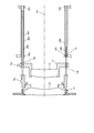
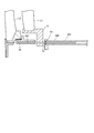
- FIG. 5A is a cross-sectional view taken along line AA in FIG. 4, and FIG. 5B is a cross-sectional view taken along line BB in FIG. It is a figure which takes out and shows the 4th, 6th group lens sliding cylinder, the 5th group lens sliding cylinder, and its vicinity.
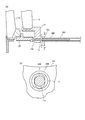
- FIG. 8A is a diagram for explaining the first modification
- FIG. 8B is a cross-sectional view taken along the line CC of FIG. 8A
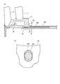
- FIG. 9A is a diagram for explaining the second modification
- FIG. 9B is a cross-sectional view taken along the line DD of FIG. 9A
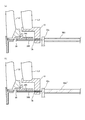
- FIG. 10A is a diagram for explaining the third modification
- FIG. 10B is a diagram for explaining the fourth modification. It is a figure for demonstrating the modification 5.
- FIG. 10A is a diagram for explaining
- FIG. 1 schematically shows a camera 500 according to the present embodiment.
- the camera 500 includes an imaging unit 200 and a lens barrel 100.
- the imaging unit 200 includes a housing 210, an optical system including a primary mirror 212, a pentaprism 214, and an eyepiece optical system 216 housed in the housing 210, a focus detection device 230, a shutter 234, and an image sensor 238.
- the main mirror 212 guides most of the incident light incident from the lens barrel 100 to the focusing screen 222 disposed above.
- the focusing screen 222 is disposed at a focus position of the optical system in the lens barrel 100 and forms an image formed by the optical system in the lens barrel 100.
- the pentaprism 214 guides the image formed on the focusing screen 222 to the eyepiece optical system 216 via the half mirror 224 after reflection. Thereby, the eyepiece optical system 216 can observe the image on the focusing screen 222 as a normal image.
- the half mirror 224 superimposes a display image formed on the finder LCD 226 indicating the shooting conditions, setting conditions, and the like on the image of the focusing screen 222. Accordingly, at the exit end of the eyepiece optical system 216, it is possible to observe a state in which the image on the focusing screen 222 and the image on the viewfinder LCD 226 are superimposed.
- a part of the light emitted from the pentaprism 214 is guided to the photometry unit 228, and the photometry unit 228 measures the intensity of the incident light, its distribution, and the like.
- the focus detection device 230 uses the light transmitted through the primary mirror 212 and reflected by the secondary mirror 232 provided on the back side of the primary mirror 212 to adjust the focus of the optical system in the lens barrel 100 ( Detect focus state. Note that the primary mirror 212 and the secondary mirror 232 are raised to a position indicated by a broken line in FIG. 1 so as to be retracted from the optical path of incident light incident from the lens barrel 100 at the time of photographing.
- the shutter 234 is disposed behind the primary mirror 212 (behind the optical path of incident light incident from the lens barrel 100), and performs an opening operation in conjunction with the ascending operation of the primary mirror 212 and the secondary mirror 232 at the time of shooting. Do. In a state where the shutter 234 is opened, incident light from the lens barrel 100 enters the image sensor 238 via the optical filter 236. The image sensor 238 converts an image formed by incident light into an electrical signal.
- the main LCD 240 has a display screen portion exposed to the outside of the casing 210. On the display screen of the main LCD 240, various setting information and the like in the imaging unit 200 are displayed in addition to the video (captured video) formed on the imaging device 238.
- the main control unit 250 comprehensively controls various operations of the above-described units.
- the main control unit 250 drives the optical system (lenses L1 to L6) in the lens barrel 100 with reference to the information on the focus adjustment state of the optical system detected by the focus detection device 230 in the imaging unit 200. (Autofocus), referring to the amount of operation of the optical system in the lens barrel 100, the fact that it is in focus is displayed on the finder LCD 226 (focus aid).
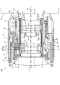
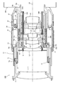
- FIGS. 2 and 3 are sectional views of the lens barrel 100.
- FIG. 2 shows a state in which the lens barrel 100 is at the wide-angle end
- FIG. 3 shows a state in which the lens barrel 100 is zoomed to the telephoto end.
- the lens barrel 100 includes a first group lens L1, a second group lens L2, a third group lens L3, a fourth group lens L4, and a fifth group lens arranged on a common optical axis AX. L5 and a 6-group lens L6.
- the first group lens L1 side (objective side) in the optical axis AX direction is the front side
- the sixth group lens L6 side (image side) is the rear side.
- the lens barrel 100 includes a fixed barrel 10, a first group lens sliding cylinder 11 that holds the first group lens L1, and a second group lens sliding cylinder that holds the second group lens L2. 12, a third group lens sliding cylinder 13 holding the third group lens L3, a fourth group lens sliding cylinder 14 holding the fourth group lens L4 and the sixth group lens L6, and 5 holding the fifth group lens L5.
- the fixed cylinder 10 is fixed to the imaging unit 200 at the base 10a.
- the fixed cylinder 10 that is, the lens barrel 100 is in contact with the imaging unit 200 by the end surface 10 b of the fixed cylinder 10 on the imaging unit 200 side being in close contact with the imaging unit 200 (the casing 210 in FIG. Positioned.
- the fixed cylinder 10 supports the guide pipe 36A at a pair of protrusions 33a and 33b provided in the vicinity of the upper part (ceiling part) inside thereof, and a pair of protrusions provided in the vicinity of the lower part of the inside thereof. In 33c and 33d, the guide pipe 36B is supported.
- These guide pipes 36A and 36B are arranged at positions that oppose each other by 180 ° with respect to the optical axis (AX) of the lens barrel 100 (positions that are substantially the same distance from the optical axis and that face each other across the optical axis). ing.
- a guide pipe 35A is inserted inside the guide pipe 36A (having a double structure of guide pipes).
- the outer diameter of the guide pipe 35A is set to be substantially the same as the inner diameter of the guide pipe 36A.
- substantially the same diameter means a dimension in which a gap that does not hinder the sliding of the guide pipe 35A is formed between the guide pipe 36A and the guide pipe 35A.
- the guide pipe 35A can be slid along the inner peripheral surface of the guide pipe 36A.
- a high-strength and lightweight material, stainless steel, or the like can be used as a material of the guide pipes 36A and 36B and the guide pipe 35A.
- the first group lens sliding cylinder 11 is connected to a zoom drive cylinder 16 provided inside the first group lens sliding cylinder 11 so as to be interlocked. Specifically, the cam pin 75 implanted in the first group lens sliding cylinder 11 is engaged with a cam groove 16 a formed in the zoom driving cylinder 16.
- the zoom drive cylinder 16 is connected to a zoom operation ring 18 that can freely rotate around the optical axis AX at the outermost periphery of the lens barrel 100.
- a driving force transmission pin 19 projecting outward from the zoom driving cylinder 16 is engaged with an operation groove 18 a parallel to the optical axis AX formed on the inner surface of the zoom operation ring 18.
- the zoom drive cylinder 16 rotates in conjunction with the rotation of the zoom operation ring 18.
- the zoom operation ring 18 cannot be moved in the front-rear direction, and an anti-slip rubber layer is provided on the outer peripheral surface thereof.
- the zoom operation ring 18 is rotated by the user during zooming.
- the zoom drive cylinder 16 is rotatable with respect to the zoom guide cylinder 22 provided inside thereof.
- the zoom guide tube 22 is formed with a cam groove 22 a, and the zoom guide tube 22 and a straight groove 16 b formed through the zoom drive tube 16.
- the rotary connecting member 21 fixed to the cam ring 20 provided on the inner side of the fixed cylinder 10 is engaged.
- the zoom driving cylinder 16 when the zoom operation ring 18 is rotated, the zoom driving cylinder 16 is rotated by the action of the driving force transmission pin 19, and the first group lens sliding cylinder 11 is moved in the front-rear direction by the action of the rotation and the cam pin 75. It moves in the direction along the optical axis AX. Further, when the zoom driving cylinder 16 is rotated by the rotation of the zoom operation ring 18, this rotational force is transmitted to the cam ring 20 via the rotary connecting member 21, so that the cam ring 20 moves in the front-rear direction while rotating. The zoom guide tube 22 moves in the front-rear direction without rotating.
- a cover cylinder 17 is provided between the zoom operation ring 18 and the first group lens sliding cylinder 11. As shown in FIGS. 2 and 3, the cover cylinder 17 moves in the front-rear direction in accordance with the first group lens sliding cylinder 11, and seals between the zoom operation ring 18 and the first group lens sliding cylinder 11. This is to stop the dust from entering the lens barrel 100.
- FIG. 4 is a view showing the second group lens sliding cylinder 12, the third group lens sliding cylinder 13, and the vicinity thereof.
- the second group lens sliding cylinder 12 is provided so as to surround the holding cylinder 24 that holds the second group lens L ⁇ b> 2, the holding ring 26 fixed to the holding cylinder 24, and the outer periphery of the holding cylinder 24.
- the holding cylinder 24 and the pressing ring 26 are fixed by screwing or the like, and sandwich the outer edge portion of the second group lens L2.
- the engagement cylinder 28 cantilever-supports two guide bars 30A and 30B. These two guide bars 30A and 30B are disposed at symmetrical positions (positions facing 180 °) across the optical axis AX.
- the guide bar 30A is a columnar member that is slidably inserted into the guide pipe 35A inserted into the guide pipe 36A.
- the inner diameter of the guide pipe 35A and the outer diameter of the guide bar 30A are set to be substantially the same.
- substantially the same diameter means a dimension in which a gap that does not hinder the sliding of the guide bar 30A is formed between the guide pipe 35A and the guide bar 30A.
- the guide bar 30A and the guide pipe 35A may not be in surface contact, and may be in point contact only at two points near one end and the other end of the guide pipe 36A.
- the guide bar 30 ⁇ / b> B is a columnar member that is inserted into the guide pipe 36 ⁇ / b> B through an oblong hole 43 formed through the protrusion 33 c.
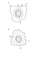
- FIG. 5A shows a cross-sectional view taken along line AA of FIG.
- the diameter of the cross section of the guide bar 30B is substantially the same as the width of the oblong hole 43 (the width in the horizontal direction of FIG. 5A), that is, the slide of the guide bar 30B.
- the dimensions are set so that there is no hindrance.
- the movement of the second group lens sliding cylinder 12 in the rotational direction around the guide bar 30 ⁇ / b> A is regulated by contact between the guide bar 30 ⁇ / b> B and the inner peripheral surface of the oval hole 43.
- the inner diameter of the guide pipe 36B is set larger than that of the guide bar 30B, and a gap is secured between the guide bar 30B (the guide bar 30B and the guide pipe 36B are Contactless).
- the material of the guide bars 30A, 30B a material having high strength and light weight, such as stainless steel, can be used as in the case of the guide pipes 36A, 36B, 35A.
- the guide bars 30A and 30B are fixed to the engaging cylinder 28 through a process such as adhesion or press fitting.
- a protruding follower 28 a is formed on a part of the outer peripheral surface of the engagement cylinder 28. As shown in FIG. 2, the follower 28 a is engaged with a circumferential groove 32 c of the interlocking ring 32 provided outside the engagement cylinder 28. The follower 28a is disposed in the vicinity of the guide bar 30A, that is, in the vicinity of an extension shaft obtained by extending the central axis of the guide bar 30A.
- an interlocking groove 32a and a cam follower 32b are further formed.
- One end of an interlocking key 34 having a substantially L-shape is engaged with the interlocking groove 32a.
- the interlocking key 34 is connected to a focus ring 37 provided on the outer peripheral portion of the fixed cylinder 10, and moves in a rotation direction around the optical axis AX as the focus ring 37 rotates about the optical axis AX. To do.
- the interlocking key 34 moves in the rotation direction around the optical axis AX, the interlocking ring 32 rotates around the optical axis AX.
- the interlock key 34 is also connected to a motor 38 provided in the motor chamber 10 c of the fixed cylinder 10. Therefore, the interlocking ring 32 also rotates around the optical axis AX by the movement of the interlocking key 34 in the rotational direction around the optical axis AX accompanying the rotational operation of the motor 38.
- the cam follower 32 b is engaged with a cam groove 20 b formed in the cam ring 20. Therefore, when the interlocking ring 32 rotates, the interlocking ring 32 and the members (the second group lens sliding cylinder 12, the guide bars 30A and 30B, the second group lens L2) are connected to the cam groove 20b and the cam follower. By the action of 32b, it moves in the front-back direction. In this movement in the front-rear direction, the interlocking ring 32 moves in the front-rear direction while rotating around the optical axis AX.
- the second group lens sliding cylinder 12 and the second group lens L2 connected to the guide bar 30A are arranged around the optical axis. Move back and forth without rotating in the direction.
- the cam follower 32b is disposed in the vicinity of the guide bar 30A, that is, in the vicinity of an extension shaft obtained by extending the central axis of the guide bar 30A.
- the third group lens sliding cylinder 13 includes a circular hole 13a and an oval hole 13b.
- the inner diameter of the circular hole 13a is the same as the outer diameter of the guide pipe 35A.
- the third group lens sliding cylinder 13 holds the guide pipe 35A in a state where the guide pipe 35A is inserted through the circular hole 13a. In this case, the guide pipe 35A is fixed to the third group lens sliding cylinder 13 through a process such as adhesion or press fitting.
- the oval hole 13b has an oval shape as shown in FIG. 5B, which is a cross-sectional view taken along the line BB of FIG.
- the width of the oval hole 13b (the width in the horizontal direction in FIG. 5B) is set to be approximately the same as the diameter of the guide bar 30B, that is, a size that does not interfere with the sliding of the third group lens sliding cylinder 13.
- the movement of the third group lens sliding cylinder 13 in the rotational direction around the guide pipe 35A is restricted by the contact between the guide bar 30B and the inner peripheral surface of the oval hole 13b.
- a groove having a U-shaped cross section having the same function as the oval hole 13b may be formed in the third group lens sliding cylinder 13.
- a cam follower 13c is provided in the vicinity of the circular hole 13a of the third group lens sliding cylinder 13.
- the cam follower 13 c is engaged with a cam groove 20 d formed in the cam ring 20. Therefore, when the cam ring 20 rotates, the third group lens sliding cylinder 13 moves in the front-rear direction by the action of the cam groove 20d and the cam follower 13c. In this movement in the front-rear direction, the guide pipe 35A is moved only in the front-rear direction by the guide pipe 36B. Therefore, the third group lens sliding cylinder 13 and the third group lens L3 connected to the guide pipe 35A are Move back and forth without rotating.
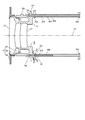
- FIG. 6 is a view showing the fourth and sixth group lens sliding cylinders 14 and the fifth group lens sliding cylinder 15 and the vicinity thereof.
- the fourth and sixth lens group sliding cylinders 14 hold the fourth lens group L4 and the sixth lens group L6 at a predetermined interval in the optical axis AX direction.
- the fifth group lens sliding cylinder 15 holds the fifth group lens L5 between the fourth group lens L4 and the sixth group lens L6.
- the fourth and sixth group lens sliding cylinders 14 have two engaging portions 14a and 14b that engage with the guide pipe 36A, and one engaging portion 14c that engages with the guide pipe 36B.
- the fifth group lens sliding cylinder 15 includes two engaging portions 15a and 15b that engage with the guide pipe 36A and one engaging portion 15c that engages with the guide pipe 36B.
- the engaging portions 14a, 14b, 15a, 15b have circular through holes.
- the through hole has substantially the same diameter as the guide pipe 36A, and the fourth and sixth group lens sliding cylinders 14 and the fifth group lens sliding cylinder 15 have the guide pipe 36A in a state where the guide pipe 36A is inserted into the through hole. Is guided in the front-rear direction.
- substantially the same diameter means that a gap is formed between the guide pipe 36 ⁇ / b> A and the through-hole so as not to interfere with the sliding of the fourth and sixth group lens sliding cylinders 14 and the fifth group lens sliding cylinder 15. Means.
- the guide pipe 36A supports the total weight of the fourth and sixth group lens sliding cylinders 14 and the fifth group lens sliding cylinder 15 to 1/2 of the total weight (depending on the attitude of the lens barrel 100).
- the engaging portions 14c and 15c have U-shaped grooves.
- the width of the U-shaped groove is set to be approximately the same as the diameter of the guide pipe 36B, that is, a size that does not hinder the sliding of the fourth and sixth group lens sliding cylinders 14 and the fifth group lens sliding cylinder 15.
- the movement of the fourth and sixth group lens sliding cylinders 14 and the fifth group lens sliding cylinder 15 in the rotational direction around the guide pipe 36A is restricted by the contact between the guide pipe 36B and the engaging portions 14c and 15c.
- an elongated circular hole having a function similar to that of the U-shaped groove may be formed.
- the fourth and sixth group lens sliding cylinders 14 and the fifth group lens sliding cylinder 15 are driven in the front-rear direction (optical axis AX direction) in conjunction with the rotational operation of the cam ring 20 around the optical axis AX. To do.
- the zoom drive cylinder 16 rotates, and the first lens group sliding cylinder 11 and the first lens group L1 are moved forward via the cam groove 16a and the cam pin 75. Go straight on.
- the cam ring 20 is rotated via the rotary connecting member 21 and the like as described above.
- the rotational force and the forward moving force also act on the interlocking ring 32 via the cam follower 32b.
- the interlocking ring 32 is operated by the interlocking key 34 (fixed state) that engages with the interlocking groove 32a. Since it is guided only in the front-rear direction, it goes straight ahead without rotating.
- the engagement cylinder 28 that is, the second group lens sliding cylinder 12
- the second group lens L2 that engage with the interlocking ring 32 move in the forward direction.
- the third lens group sliding cylinder 13 and the third lens group L3 engaged with the cam ring 20 move in the forward direction.
- the rotation of the cam ring 20 also moves the fourth and sixth group lens sliding cylinders 14 and the fifth group lens sliding cylinder 15 (the fourth to sixth group lenses L4 to L6) in the forward direction.
- each of the first to sixth lens groups L1 to L6 moves forward by a different distance (however, the lenses L4 and L6 are the same distance) as the zoom operation ring 18 rotates. It is supposed to be.
- FIG. 7 shows a state where the second group lens sliding cylinder 12 and the third group lens sliding cylinder 13 have moved forward from the state of FIG. 4 due to the zooming.
- the guide bar 30B has the protrusion 33c (oval hole 43) and the third group lens sliding cylinder.
- the state in contact with the moving cylinder 13 (the oblong hole 13b) is continuously maintained.
- the guide bar 30A continues to maintain the insertion state with respect to the guide pipe 35A, and the guide pipe 35A continues to maintain the insertion state with respect to the guide pipe 36A.
- the interlock key 34 moves in the rotation direction around the optical axis AX, as described above, the interlock key 34
- the interlocking ring 32 to be engaged rotates around the optical axis AX.
- the interlocking ring 32 moves in the forward direction along the cam follower 32 b along the cam groove 20 b of the cam ring 20.
- the engaging cylinder 28 that is, the second lens group sliding cylinder 12
- the engaging cylinder 28 that is, the second lens group sliding cylinder 12
- the driving force in the optical axis AX direction can be efficiently applied to the interlocking ring 32 and the engagement cylinder 28.
- the cam ring 20 since the cam ring 20 is in a non-rotating fixed state, the first lens group L1 and the third to sixth lens groups L3 to L6 do not move in the front (rear) direction.
- the rotation of the motor 38 during focusing is controlled by the main control unit 250 in FIG. 1 based on the detection result of the focus detection device 230. That is, autofocus is executed by the rotation control of the motor 38 by the main control unit 250.
- the lens barrel 100 and the imaging unit 200 are electrically connected by a connection terminal provided between the lens barrel 100 and the imaging unit 200, and thereby, the lens barrel 100 (for example, Electric power is supplied to the motor 38 and the like from the imaging unit 200 side.
- the guide pipe 35A slides in the direction of the optical axis AX along the inner peripheral surface of the guide pipe 36A fixed to the fixed cylinder 10.
- the guide bar 30A slides in the direction of the optical axis AX along the inner peripheral surface of the guide pipe 35A.
- the second group lens sliding cylinder 12 holding the second group lens L2 is fixed to the guide bar 30A, guided in the optical axis direction by sliding of the guide bar 30A, and the third group lens L3 is attached to the guide pipe 35A.
- the third-group lens sliding cylinder 13 to be held is fixed, and is guided in the optical axis direction by sliding the guide bar 30A.
- the second group lens sliding cylinder 12 and the third group lens sliding cylinder 13 can be separately guided by the double-structured guide pipes 35A and 36A and the guide bar 30A. It is possible to simplify the structure in the lens barrel 100. Thereby, the space efficiency in the lens barrel 100 can be improved, and the lens barrel 100 can be downsized (increase in diameter) can be achieved. In addition, by reducing the size of the lens barrel 100, the entire camera 500 can be reduced in size.
- the guide bar 30B extending in the direction of the optical axis AX is fixed to the second group lens sliding cylinder 12 and is in contact with the third group lens sliding cylinder 13 and the fixed cylinder 10 so that the second group The movement operation (rotation operation) of the lens sliding cylinder 12 and the third group lens sliding cylinder 13 around the optical axis AX with respect to the fixed cylinder 10 is restricted.
- the rotation operation of the two lens sliding cylinders 12 and 13 can be restricted by the single guide bar 30B. From this point, the structure in the lens barrel 100 can be simplified and the space efficiency can be improved. Improvements can be made.
- the fixed cylinder 10 holds the guide pipe 36B extending in the optical axis AX direction, and the fourth and sixth group lens sliding cylinders 14 and the fifth group lens sliding cylinder 15 are guided by the guide pipe 36A. While being guided in the axial direction, the movement operation (rotation operation) in the direction around the optical axis is restricted by contacting the guide pipe 36B. As a result, the fourth and sixth group lens sliding cylinders 14 and the fifth group lens sliding cylinder 15 are guided in the front-rear direction without contact with the guide bars 30A and 30B and the guide pipe 35A. Therefore, the movement of the second group lens sliding cylinder 12 and the third group lens sliding cylinder 13 is not hindered by the fourth group lens sliding cylinder 14 and the fifth group lens sliding cylinder 15. As a result, the force required to move the second group lens sliding cylinder 12 and the third group lens sliding cylinder 13 can be reduced, so that the burden on the motor 38 or the user who rotates the focus ring 37 is reduced. can do.
- the guide bar 30B is inserted into the guide pipe 36B, mechanical interference between the guide pipe 36B and the guide bar 30B can be avoided, and the guide pipe 36B and the guide bar can be avoided.
- the structure in the lens barrel 100 can be simplified and the space efficiency can be improved.
- the double weight guide of the total weight of the fourth and sixth group lens sliding cylinders 14 and the fifth group lens sliding cylinder 15 to 1/2 of the total weight (depending on the attitude of the lens barrel 100).
- Pipes 35A and 36A support.
- at least half of the total weight of the fourth and sixth group lens sliding cylinders 14 and the fifth group lens sliding cylinder 15 is supported by the guide pipes 35A and 36A on the side where the rigidity is high and the deformation is suppressed. By doing so, it is possible to suppress optical axis misalignment and the like of the 4th to 6th group lenses L4 to L6.
- the guide bar 30A and the guide pipes 35A and 35B have substantially the same length. Therefore, the distance that the guide pipe 35A guides the guide bar 30A and the guide pipe 36A guide the guide pipe 35A. It is possible to increase the guiding distance. Thereby, it is possible to lengthen the moving length of the second group lens sliding cylinder 12 and the third group lens sliding cylinder 13. Further, in the present embodiment, since the double structure by the guide pipes 35A and 36A is adopted, the movement amount of the second group lens sliding cylinder 12 is set to the length of the guide bar 30A and the length of the third group lens sliding cylinder 13 is increased. The amount of movement is added. This makes it possible to increase the amount of movement of the second group lens sliding cylinder 12.
- the guide pipes 36A and 36B are disposed at positions that oppose each other by 180 ° with respect to the optical axis AX of the lens barrel 100, so that the distance between the guide bars 30A and 30B can be made as large as possible. it can.
- it is possible to reduce the force required when the rotation of the second group lens sliding cylinder 12 and the third group lens sliding cylinder 13 around the optical axis AX direction is restricted by the guide bar 30B, and consequently the guide bar 30B. It is possible to reduce the force, deformation and the like applied to the.
- the guide bar 30B can be made shorter than the guide bar 30A, so that the lens barrel 100 can be reduced in weight compared to the case where the guide bar 30B has the same length as the guide bar 30A. It becomes possible.
- the guide bar 30B fixed to the second group lens sliding cylinder 12 includes the oval hole 43 formed in the protrusion 33c of the fixed cylinder 10 and the oval hole of the third group lens sliding cylinder 13.
- the case where the rotation operation of the second group lens sliding cylinder 12 and the third group lens sliding cylinder 13 is restricted by contacting with 13b has been described.
- the present invention is not limited to this, and the rotation operation of the second group lens sliding cylinder 12 and the third group lens sliding cylinder 13 can be performed by adopting the configuration shown in FIGS. 8 to 11 (Modifications 1 to 5). It may be regulated.
- FIG. 8A and 8B show a configuration according to the first modification.
- FIG. 8B is a cross-sectional view taken along the line CC of FIG.
- a cap-like member 71 in which an oblong hole 71a is formed is provided on a part (front end) of the guide pipe 36B.
- the guide bar 30B keeps in contact with the cap-shaped member 71 (the oblong hole 71a) and the third group lens sliding cylinder 13 (the oblong hole 13b). It is possible to restrict the rotational movement of the sliding cylinder 12 and the third group lens sliding cylinder 13.
- FIGS. 9A and 9B show a configuration according to the second modification.
- FIG. 9B is a cross-sectional view taken along the line DD of FIG.
- a guide pipe 36B ' having a flat shape as a whole is employed. Even in this case, since the guide bar 30B and a part of the inner peripheral surface of the guide pipe 36B ′ are kept in contact with each other, the second group lens sliding cylinder 12 and the third group lens sliding cylinder 13 are similar to the above embodiment. It is possible to regulate the rotation operation. Even if the guide pipe 36B 'having a flat shape is employed, there is no problem in the moving operation of the fourth and sixth group lens sliding cylinders 14 and the fifth group lens sliding cylinder 15.
- FIG. 10A shows a configuration according to the third modification.
- the guide bar 30B is fixed to the protruding portion 33c of the fixed cylinder 10.
- the U-shaped groove 28h is provided in the engaging cylinder 28 of the second group lens sliding cylinder 12.
- the guide bar 30B is kept in contact with the U-shaped groove 28h while the second lens group sliding cylinder 12 moves in the front-rear direction.
- the engaging cylinder 28 may be formed with an oval hole having the same function as the U-shaped groove instead of the U-shaped groove 28h.
- the guide pipe 36B is adopted.
- the guide pipe 36B is not limited to this, and the guide pipe 36B is replaced by a rod-shaped member (guide bar) 36B "as in the fourth modification of FIG. 10B. It is good also as changing to.
- FIG. 11 shows a configuration according to the fifth modification.
- the guide bar 30B is fixed (held) to the third group lens sliding cylinder 13.
- the U-shaped groove 28 h is provided in the engaging cylinder 28 of the second group lens sliding cylinder 12.
- the guide bar 30B is kept in contact with the U-shaped groove 28h and the oval hole 43 while the second group lens sliding cylinder 12 and the third group lens sliding cylinder 13 move in the front-rear direction. Even if this modification 5 is adopted, it is possible to restrict the rotational movement of the second group lens sliding cylinder 12 and the third group lens sliding cylinder 13 as in the above embodiment.
- the guide pipe has a double structure.
- the present invention is not limited to this, and the guide pipe may be triple or more. In this case, it is possible to fix a lens sliding cylinder to each guide pipe.
- the guide bar 30B and the guide pipe 36B are arranged on the same axis.
- the present invention is not limited to this, and the guide bar 30B and the guide pipe 36B are arranged on different axes. May be.
- a rod-shaped member (a member indicated by reference numeral “36” in FIG. 10B) may be used.
- all of the first to sixth lens groups L1 to L6 move in the optical axis AX direction during zooming, and only the second lens group L2 moves in the optical axis AX direction during focusing.
- the present invention is not limited to this.
- any of the lenses L1, L3 to L6 other than the second group lens L2 may be moved in the optical axis AX direction.
- the method of performing focusing by moving the first group lens L1 is called a front lens payout method.
- all of the first to sixth group lenses L1 to L6 or a plurality of these lenses may be moved.
- the method in which all the lenses are moved is called the entire extension method.
- the guide pipes 36A and 36B are configured separately from the fixed cylinder 10, and the guide pipes 36A and 36B are supported by the fixed cylinder 10.
- the present invention is not limited to this.
- the guide pipes 36A and 36B and the fixed cylinder 10 may be integrally formed.
- the fourth group lens L4 and the sixth group lens L6 are held by the common lens sliding cylinder 14 .
- the present invention is not limited to this, and the fourth group lens L4 and the sixth group lens L6 are Alternatively, they may be held by separate lens sliding cylinders.
- the lens barrel includes at least a lens held by one lens sliding cylinder fixed to the guide bar 30A and a lens held by another lens sliding cylinder fixed to the guide bar 30B. It only has to have.
- the present invention is not limited to this, and an optical member such as a mirror or an image sensor can also be used.
Landscapes
- Physics & Mathematics (AREA)
- General Physics & Mathematics (AREA)
- Optics & Photonics (AREA)
- Engineering & Computer Science (AREA)
- General Engineering & Computer Science (AREA)
- Lens Barrels (AREA)
Abstract
所定軸(AX)方向に延びる第1筒状部材(36A)と、前記第1筒状部材の内周面に沿って、前記所定軸方向にスライドする第2筒状部材(35A)と、前記第2筒状部材の内周面に沿って、前記所定軸方向にスライドする軸部材(30A)と、前記軸部材に固定され、当該軸部材の前記第2筒状部材に対するスライドにより前記所定軸方向にガイドされる、第1光学部材(L2)を保持する第1保持部材(12)と、を備えた、構造の簡素化が図られたレンズ鏡筒(100)を提供する。
Description
本発明は、レンズ鏡筒及び撮像装置に関する。
従来、カメラに取り付けられるレンズ鏡筒は、カメラに装着された状態で、カメラに対して固定される固定筒と、その固定筒に対して回転するカム筒と、そのカム筒の回転により光軸方向に移動する複数のレンズ群を備えている(例えば、特許文献1参照)。
このようなレンズ鏡筒は、光学性能を確保するために、設計上において種々の制約がある。また、当該制約下で光学性能を確保するためには、レンズ鏡筒内の構造は、簡素化されているほうが良い。
そこで本発明は上記の課題に鑑みてなされたものであり、構造の簡素化が図られたレンズ鏡筒及び撮像装置を提供することを目的とする。
本発明のレンズ鏡筒は、所定軸方向に延びる第1筒状部材と、前記第1筒状部材の内周面に沿って、前記所定軸方向にスライドする第2筒状部材と、前記第2筒状部材の内周面に沿って、前記所定軸方向にスライドする軸部材と、前記軸部材に固定され、当該軸部材の前記第2筒状部材に対するスライドにより前記所定軸方向にガイドされる、第1光学部材を保持する第1保持部材と、を備えるレンズ鏡筒である。
この場合において、前記第2筒状部材に固定され、前記第2筒状部材の前記第1筒状部材に対するスライドにより前記所定軸方向にガイドされる、第2光学部材を保持する第2保持部材を更に備える構成としてもよい。この場合、前記所定軸方向に延び、前記第1保持部材及び前記第2保持部材のそれぞれに接触され、前記第1保持部材及び前記第2保持部材の前記所定軸回り方向の移動動作を規制する規制部材を更に備えることとしてもよい。この場合、前記第1筒状部材が固定される基準部材を更に備えることとしてもよい。この場合、前記規制部材は、前記所定軸方向に延びる棒形状を有し、前記第1保持部材、前記第2保持部材及び前記基準部材のいずれか1つに固定されていることとしてもよい。また、前記基準部材は、前記所定軸方向に延びる延伸部材を有し、前記第1筒状部材及び前記延伸部材のいずれか一方を用いて前記所定軸方向にガイドされ、前記第1筒状部材及び前記延伸部材のいずれか他方に接触することで、前記所定軸回り方向の移動動作が規制される、第3光学部材を保持する第3保持部材を更に備えることとしてもよい。この場合、前記延伸部材は、筒形状を有し、前記規制部材は、軸状であり、前記第1保持部材及び前記第2保持部材のいずれかに固定され、前記延伸部材の内部に挿入されていることとしてもよい。
また、前記規制部材と、前記延伸部材の内周面の一部とが接触することで、前記第1保持部材及び前記第2保持部材の前記基準部材に対する前記所定軸回り方向の移動動作が規制されていることとしてもよい。
本発明の撮像装置は、本発明のレンズ鏡筒と、前記レンズ鏡筒により結ばれた画像を撮像する撮像部と、を備える撮像装置である。
本発明のレンズ鏡筒及び撮像装置は、構造を簡素化できるという効果を奏する。
以下、一実施形態に係るカメラ及び当該カメラが具備するレンズ鏡筒について、図1~図7に基づいて詳細に説明する。
図1には、本実施形態に係るカメラ500が模式的に示されている。図1に示すようにカメラ500は、撮像部200と、レンズ鏡筒100と、を備える。
撮像部200は、筐体210と、筐体210内に収容された主鏡212、ペンタプリズム214、接眼光学系216を含む光学系と、焦点検出装置230と、シャッタ234と、撮像素子238と、メインLCD240と、主制御部250と、を有する。
主鏡212は、図1の状態では、レンズ鏡筒100から入射した入射光の大半を上方に配置されたフォーカシングスクリーン222に導く。フォーカシングスクリーン222は、レンズ鏡筒100内の光学系の合焦位置に配置され、レンズ鏡筒100内の光学系により形成された画像を結像させる。
ペンタプリズム214は、フォーカシングスクリーン222に結像された画像を、反射した後、ハーフミラー224を介して、接眼光学系216まで導く。これにより、接眼光学系216では、フォーカシングスクリーン222上の映像を正像として観察することができる。この場合、ハーフミラー224は、ファインダLCD226に形成された撮影条件や設定条件等を示す表示画像をフォーカシングスクリーン222の映像に重畳させる。したがって、接眼光学系216の出射端においては、フォーカシングスクリーン222の映像とファインダLCD226の画像とが重ね合わせられた状態を観察することができる。なお、ペンタプリズム214の出射光の一部は、測光部228に導かれ、当該測光部228にて、入射光の強度及びその分布等が測定される。
焦点検出装置230は、主鏡212を透過し、かつ主鏡212の裏面側に設けられた副鏡232にて反射された光を用いて、レンズ鏡筒100内の光学系の焦点調整状態(ピント状態)を検出する。なお、主鏡212及び副鏡232は、撮影の際には、レンズ鏡筒100から入射する入射光の光路から退避するように、図1に破線にて示す位置まで上昇する。
シャッタ234は、主鏡212後方(レンズ鏡筒100から入射する入射光の光路後方)に配置され、撮影の際には、主鏡212及び副鏡232の上昇動作と連動して、開放動作を行う。シャッタ234が開放された状態では、光学フィルタ236を介して撮像素子238にレンズ鏡筒100からの入射光が入射する。撮像素子238は、入射光が形成する画像を電気信号に変換する。
メインLCD240は、その表示画面部分が筐体210の外部に露出した状態となっている。このメインLCD240の表示画面上には、撮像素子238上に形成された映像(撮影された映像)のほか、撮像部200における各種設定情報などが表示される。
主制御部250は、上記各部の種々動作を統括的に制御する。また、主制御部250は、撮像部200内の焦点検出装置230が検出した光学系の焦点調整状態の情報を参照して、レンズ鏡筒100内の光学系(レンズL1~L6)を駆動したり(オートフォーカス)、レンズ鏡筒100内の光学系の動作量を参照して、合焦していることをファインダLCD226に表示したりする(フォーカスエイド)。
次に、レンズ鏡筒100の構成について、図2~図7に基づいて詳細に説明する。
図2、図3には、レンズ鏡筒100の断面図が示されている。これらのうち、図2は、レンズ鏡筒100が広角端にある状態を示し、図3は、レンズ鏡筒100が、望遠端までズームされた状態を示す。これら図2、図3に示すように、レンズ鏡筒100は、共通の光軸AX上に配列された1群レンズL1、2群レンズL2、3群レンズL3、4群レンズL4、5群レンズL5、6群レンズL6を有する。なお、以下においては、光軸AX方向の1群レンズL1側(対物側)を前側、6群レンズL6側(像側)を後側として説明する。
レンズ鏡筒100は、図2、図3に示すように、固定筒10と、1群レンズL1を保持する1群レンズ摺動筒11と、2群レンズL2を保持する2群レンズ摺動筒12と、3群レンズL3を保持する3群レンズ摺動筒13と、4群レンズL4及び6群レンズL6を保持する4,6群レンズ摺動筒14と、5群レンズL5を保持する5群レンズ摺動筒15と、を備える。
固定筒10は、基部10aにおいて、撮像部200に固定される。この固定状態では、固定筒10の撮像部200側の端面10bが撮像部200(図1の筐体210)に密接することにより、固定筒10、すなわちレンズ鏡筒100が撮像部200に対して位置決めされる。固定筒10は、その内部の上側部分(天井部分)近傍に設けられた一対の突起部33a,33bにおいて、ガイドパイプ36Aを支持し、その内部の下側部分近傍に設けられた一対の突起部33c,33dにおいて、ガイドパイプ36Bを支持する。これらガイドパイプ36A,36Bは、レンズ鏡筒100の光軸(AX)を基準として180°対向する位置(光軸からの距離が略同一で、光軸を挟んで相対向する位置)に配置されている。なお、ガイドパイプ36Aの内部には、ガイドパイプ35Aが挿入されている(ガイドパイプの2重構造となっている)。ガイドパイプ35Aの外径は、ガイドパイプ36Aの内径とほぼ同一に設定されている。ここで、ほぼ同径とは、ガイドパイプ35Aのスライドに支障が無い程度の隙間が、ガイドパイプ36Aとガイドパイプ35Aの間に形成される寸法を意味する。これにより、ガイドパイプ35Aは、ガイドパイプ36Aの内周面に沿ったスライド移動が可能となっている。なお、ガイドパイプ36A,36B及びガイドパイプ35Aの材料としては、強度が高く、軽量な材料、ステンレスなどを採用することができる。
1群レンズ摺動筒11は、当該1群レンズ摺動筒11の内側に設けられたズーム駆動筒16と連動可能に連結されている。具体的には、1群レンズ摺動筒11に植設されたカムピン75が、ズーム駆動筒16に形成されたカム溝16aに係合した状態となっている。
一方、ズーム駆動筒16は、レンズ鏡筒100の最外周において光軸AX回りの回転が自在とされたズーム操作環18と連動可能に連結されている。具体的には、ズーム駆動筒16から外側に突設された駆動力伝達ピン19が、ズーム操作環18の内面に形成された光軸AXに平行な操作溝18aに係合している。これにより、ズーム駆動筒16は、ズーム操作環18の回転に連動して回転する。ズーム操作環18は、前後方向への移動ができないようになっており、その外周面には滑り止めのゴム層が設けられている。ズーム操作環18は、変倍動作(ズーミング)の際に、ユーザによって回転されるものである。
また、ズーム駆動筒16は、その内側に設けられたズーム用案内筒22に対して回転可能とされている。ズーム用案内筒22には、図2、図3の下半部に示すように、カム溝22aが貫通形成され、このズーム用案内筒22と、ズーム駆動筒16に貫通形成された直進溝16bとには、固定筒10の内側に設けられたカムリング20に固定された回転連結部材21が係合している。
上記構造によると、ズーム操作環18が回転されると、駆動力伝達ピン19の作用によりズーム駆動筒16が回転し、その回転とカムピン75の作用により、1群レンズ摺動筒11が前後方向(光軸AXに沿った方向)に移動する。また、ズーム操作環18の回転により、ズーム駆動筒16が回転すると、この回転力が回転連結部材21を介してカムリング20に伝達するため、カムリング20は回転しながら前後方向に移動する。なお、ズーム用案内筒22は、回転せずに前後方向に移動する。
なお、ズーム操作環18と1群レンズ摺動筒11との間には、カバー筒17が設けられている。このカバー筒17は、図2、図3に示すように、1群レンズ摺動筒11に連れ従って前後方向に移動して、ズーム操作環18と1群レンズ摺動筒11との間を封止し、レンズ鏡筒100内への塵埃の浸入を防止するためのものである。
図4は、2群レンズ摺動筒12、3群レンズ摺動筒13及びそれらの近傍を取り出して示す図である。図4に示すように、2群レンズ摺動筒12は、2群レンズL2を保持する保持筒24と、保持筒24に固定された押さえ環26と、保持筒24の外周を取り囲む状態で設けられた係合筒28と、を有する。保持筒24と押さえ環26とは、ネジ止め等により固定され、2群レンズL2の外縁部を挟持する。
係合筒28は、2本のガイドバー30A、30Bを片持ち支持する。これら2本のガイドバー30A、30Bは、光軸AXを挟んで上下対称な位置(180°対向する位置)に配置されている。
ガイドバー30Aは、図4に示すように、ガイドパイプ36Aに挿入されたガイドパイプ35Aに対し、スライド可能に挿入された円柱状部材である。ガイドパイプ35Aの内径とガイドバー30Aの外径はほぼ同一に設定されている。ここで、ほぼ同径とは、ガイドバー30Aのスライドに支障が無い程度の隙間が、ガイドパイプ35Aとガイドバー30Aの間に形成される寸法を意味する。なお、ガイドバー30Aとガイドパイプ35Aとの間は、面接触して無くても良く、ガイドパイプ36Aの一端部近傍と他端部近傍の2点で点接触しているのみでも良い。
ガイドバー30Bは、図4に示すように、突起部33cに貫通形成された長円孔43を介して、ガイドパイプ36Bに挿入された状態とされた円柱状部材である。図5(a)には、図4のA-A線断面図が示されている。この図5(a)に示すように、ガイドバー30Bの断面の直径は、長円孔43の幅(図5(a)の紙面横方向の幅)と略同一、すなわち、ガイドバー30Bのスライドに支障が無い程度の寸法に設定されている。2群レンズ摺動筒12のガイドバー30Aを中心とした回転方向の動きは、ガイドバー30Bと長円孔43の内周面との接触により規制されている。なお、図5(a)に示すように、ガイドパイプ36Bの内径は、ガイドバー30Bよりも大きく設定され、ガイドバー30Bとの間に隙間が確保されている(ガイドバー30Bとガイドパイプ36Bは非接触となっている)。
ガイドバー30A,30Bの材料としては、ガイドパイプ36A,36B,35Aと同様、強度が高く、軽量な材料、例えばステンレスなどを採用することができる。また、ガイドバー30A,30Bは、係合筒28に対して、接着又は圧入などの処理を経て固定されている。
係合筒28の外周面の一部には、図4に示すように、突起状のフォロワ28aが形成されている。フォロワ28aは、図2に示すように、係合筒28の外側に設けられた連動リング32の周溝32cと係合している。なお、フォロワ28aは、ガイドバー30Aの近傍、すなわち、ガイドバー30Aの中心軸を延長した延長軸の近傍に配置されている。
周溝32cが形成されている連動リング32には、更に、連動溝32aと、カムフォロワ32bとが形成されている。連動溝32aには、略L字状の形状を有する連動キー34の一端部が係合している。この連動キー34は、固定筒10の外周部に設けられたピントリング37に接続されており、ピントリング37の光軸AX回りの回転に伴って、光軸AXを中心とした回転方向に移動する。このように、連動キー34が光軸AXを中心とした回転方向に移動すると、連動リング32が光軸AX回りに回転する。また、連動キー34は、固定筒10のモータ室10c内に設けられたモータ38にも接続されている。したがって、連動リング32は、モータ38の回転動作に伴う連動キー34の光軸AXを中心とした回転方向への移動によっても、光軸AX回りに回転する。
カムフォロワ32bは、カムリング20に形成されたカム溝20bに係合している。したがって、連動リング32が回転した場合には、連動リング32及びこれに連結されている部材(2群レンズ摺動筒12、ガイドバー30A、30B、2群レンズL2)が、カム溝20bとカムフォロワ32bの作用により、前後方向に移動するようになっている。この前後方向の移動において、連動リング32は、光軸AX回りに回転しながら前後方向に移動する。ただし、ガイドバー30Aの移動方向は、ガイドパイプ35A、36Aにより前後方向のみとされているので、ガイドバー30Aに接続されている2群レンズ摺動筒12及び2群レンズL2は、光軸回り方向に回転することなく前後方向に移動する。なお、カムフォロワ32bは、ガイドバー30Aの近傍、すなわち、ガイドバー30Aの中心軸を延長した延長軸の近傍に配置されている。
3群レンズ摺動筒13は、図4に示すように、円形孔13aと、長円孔13bと、を有する。
円形孔13aは、その内径が、ガイドパイプ35Aの外径と同一となっている。3群レンズ摺動筒13は、円形孔13aにガイドパイプ35Aを挿通させた状態で、ガイドパイプ35Aを保持している。この場合、ガイドパイプ35Aは、3群レンズ摺動筒13に対して、接着又は圧入などの処理を経て固定されている。
長円孔13bは、図4のB-B線断面図である図5(b)に示すように、長円形の形状を有している。長円孔13bの幅(図5(b)の紙面横方向の幅)は、ガイドバー30Bの直径と略同一、すなわち、3群レンズ摺動筒13のスライドに支障が無い程度の寸法に設定されている。3群レンズ摺動筒13のガイドパイプ35Aを中心とした回転方向の動きは、ガイドバー30Bと長円孔13bの内周面との接触により、規制されている。なお、長円孔13bに代えて、3群レンズ摺動筒13に、長円孔13bと同様の機能を有する断面U字状の溝を形成することとしてもよい。
また、3群レンズ摺動筒13の円形孔13a近傍には、図2に示すように、カムフォロワ13cが設けられている。カムフォロワ13cは、カムリング20に形成されたカム溝20dに係合している。したがって、カムリング20が回転した場合には、カム溝20dとカムフォロワ13cとの作用により、3群レンズ摺動筒13が前後方向に移動するようになっている。この前後方向の移動において、ガイドパイプ35Aの移動方向は、ガイドパイプ36Bにより前後方向のみとされているので、ガイドパイプ35Aに接続されている3群レンズ摺動筒13及び3群レンズL3は、回転することなく前後方向に移動する。
図6は、4,6群レンズ摺動筒14、5群レンズ摺動筒15及びその近傍を取り出して示す図である。図6に示すように、4,6群レンズ摺動筒14は、4群レンズL4と6群レンズL6とを光軸AX方向に所定間隔あけた状態で保持する。5群レンズ摺動筒15は、4群レンズL4と6群レンズL6との間で、5群レンズL5を保持する。
4,6群レンズ摺動筒14は、ガイドパイプ36Aに係合する2つの係合部14a,14bと、ガイドパイプ36Bに係合する1つの係合部14cと、を有する。また、5群レンズ摺動筒15は、ガイドパイプ36Aに係合する2つの係合部15a,15bと、ガイドパイプ36Bに係合する1つの係合部15cと、を有する。
係合部14a,14b、15a,15bは、円形の貫通孔を有している。この貫通孔は、ガイドパイプ36Aとほぼ同径であり、4,6群レンズ摺動筒14及び5群レンズ摺動筒15は、貫通孔にガイドパイプ36Aが挿入された状態で、ガイドパイプ36Aにより前後方向にガイドされる。ここで、ほぼ同径とは、4,6群レンズ摺動筒14及び5群レンズ摺動筒15のスライドに支障が無い程度の隙間が、ガイドパイプ36Aと貫通孔の間に形成される寸法を意味する。ガイドパイプ36Aは、4,6群レンズ摺動筒14及び5群レンズ摺動筒15の全自重~全自重の1/2(レンズ鏡筒100の姿勢によって異なる)を支持する。一方、係合部14c、15cは、U字溝を有する。U字溝の幅は、ガイドパイプ36Bの直径と略同一、すなわち、4,6群レンズ摺動筒14及び5群レンズ摺動筒15のスライドに支障が無い程度の寸法に設定されている。4,6群レンズ摺動筒14及び5群レンズ摺動筒15のガイドパイプ36Aを中心とした回転方向の動きは、ガイドパイプ36Bと係合部14c,15cとの接触により、規制されている。なお、係合部14c,15cには、U字溝に代えて、U字溝と同様の機能を有する、径方向に長い長円孔を形成してもよい。
なお、4,6群レンズ摺動筒14及び5群レンズ摺動筒15は、カムリング20の光軸AX回りの回転動作に連動して、前後方向(光軸AX方向)に駆動されるものとする。
次に、図2、図3等に基づいて、ズーム動作を行うとき(ズーミング)の各レンズL1~L6の移動動作、及びピントを合わせるとき(フォーカシング)の各レンズL1~L6の移動動作について説明する。
まず、ズーミングのときの各レンズの移動動作について説明する。ここでは、レンズ鏡筒100が広角端にある状態(図2)から、望遠端にズームされるまで(図3)の動作について説明する。
図2の状態から、ユーザによりズーム操作環18が回転されると、ズーム駆動筒16が回転し、カム溝16a及びカムピン75を介して、1群レンズ摺動筒11及び1群レンズL1が前方に直進する。また、ズーム操作環18が回転されると、前述したように回転連結部材21等を介してカムリング20が回転される。この回転に伴い、連動リング32にもカムフォロワ32bを介して、回転力と前方向の移動力とが作用するが、連動リング32は、連動溝32aと係合する連動キー34(固定状態)により、前後方向にのみガイドされているので、回転することなく前側に直進する。また、この連動リング32の直進に伴って、連動リング32に係合する係合筒28(すなわち2群レンズ摺動筒12)、及び2群レンズL2が前方向に移動する。更に、カムリング20に係合する3群レンズ摺動筒13及び3群レンズL3が前方向に移動する。
更に、カムリング20の回転は、4,6群レンズ摺動筒14及び5群レンズ摺動筒15(4~6群レンズL4~L6)も前方向に移動させる。
このように、ズーミングのときには、ズーム操作環18の回転動作に伴って、1~6群レンズL1~L6のそれぞれが前方向に、別々の距離(ただし、レンズL4とL6は同一距離)だけ移動するようになっている。
図7には、上記ズーミングにより、図4の状態から2群レンズ摺動筒12及び3群レンズ摺動筒13が前方向に移動した状態が示されている。図7に示すように、2群レンズ摺動筒12及び3群レンズ摺動筒13が前方向に移動しても、ガイドバー30Bは、突起部33c(長円孔43)及び3群レンズ摺動筒13(長円孔13b)に接触した状態を維持し続ける。また、ガイドバー30Aは、ガイドパイプ35Aに対する挿入状態を維持し続け、ガイドパイプ35Aは、ガイドパイプ36Aに対する挿入状態を維持し続ける。
次に、フォーカシングのときの各レンズの移動動作について説明する。
まず、ピントリング37がユーザにより回転されるか、あるいはモータ38が回転駆動されることにより、連動キー34が光軸AXを中心とする回転方向に移動すると、前述したように、連動キー34に係合する連動リング32が光軸AX回りに回転する。この回転により、連動リング32は、カムフォロワ32bをカムリング20のカム溝20bに沿わせて、前方向にも移動する。そして、この連動リング32の回転方向及び前方向の移動により、連動リング32の周溝32cに係合したフォロワ28aを有する係合筒28(すなわち2群レンズ摺動筒12)及び2群レンズL2も前方向に移動することになる。ここで、カムフォロワ32b及びフォロワ28aは、ガイドバー30Aの近傍に配置されているので、連動リング32及び係合筒28に対して光軸AX方向の駆動力を効率的に作用させることができる。
一方、カムリング20は、無回転の固定状態にあるため、1群レンズL1及び3~6群レンズL3~L6は前(後)方向に移動しない。
このように、フォーカシングのときには、連動キー34の回転動作に伴って、2群レンズL2のみが前(後)方向に移動するようになっている。
なお、フォーカシング時のモータ38の回転は、図1の主制御部250が、焦点検出装置230の検出結果に基づいて制御する。すなわち、主制御部250によるモータ38の回転制御により、オートフォーカスが実行される。なお、レンズ鏡筒100と、撮像部200との間は、レンズ鏡筒100と撮像部200との間に設けられる接続端子により電気的に接続されており、これにより、レンズ鏡筒100(例えばモータ38など)に、撮像部200側から電力が供給されるようになっている。
以上、詳細に説明したように、本実施形態によると、ガイドパイプ35Aが、固定筒10に固定されたガイドパイプ36Aの内周面に沿って光軸AX方向にスライドするようになっており、ガイドバー30Aが、ガイドパイプ35Aの内周面に沿って、光軸AX方向にスライドするようになっている。そして、ガイドバー30Aには、2群レンズL2を保持する2群レンズ摺動筒12が固定され、ガイドバー30Aのスライドにより光軸方向にガイドされ、ガイドパイプ35Aには、3群レンズL3を保持する3群レンズ摺動筒13が固定され、ガイドバー30Aのスライドにより光軸方向にガイドされるようになっている。このように、本実施形態では、2重構造のガイドパイプ35A,36Aと、ガイドバー30Aとにより、2群レンズ摺動筒12、3群レンズ摺動筒13を別々にガイドすることができるので、レンズ鏡筒100内の構造の簡素化を図ることが可能である。これにより、レンズ鏡筒100内のスペース効率を向上することができ、レンズ鏡筒100の小型化を図る(径大化を抑制する)ことができる。また、レンズ鏡筒100を小型化することで、カメラ500全体の小型化を図ることもできる。
また、本実施形態では、光軸AX方向に延びるガイドバー30Bが、2群レンズ摺動筒12に固定されるとともに、3群レンズ摺動筒13及び固定筒10に接触することで、2群レンズ摺動筒12及び3群レンズ摺動筒13の固定筒10に対する光軸AX回り方向の移動動作(回転動作)を規制している。これにより、1本のガイドバー30Bで、2つのレンズ摺動筒12、13の回転動作を規制することができるので、この点からも、レンズ鏡筒100内の構造の簡素化及びスペース効率の向上を図ることができる。
また、本実施形態では、固定筒10が光軸AX方向に延びるガイドパイプ36Bを保持しており、4,6群レンズ摺動筒14及び5群レンズ摺動筒15は、ガイドパイプ36Aにより光軸方向にガイドされるとともに、ガイドパイプ36Bに接触することで光軸回り方向の移動動作(回転動作)が規制されている。これにより、4,6群レンズ摺動筒14及び5群レンズ摺動筒15は、ガイドバー30A,30B、ガイドパイプ35Aとは非接触な状態で前後方向にガイドされる。したがって、2群レンズ摺動筒12や3群レンズ摺動筒13の移動を、4,6群レンズ摺動筒14及び5群レンズ摺動筒15が妨げることがない。これにより、2群レンズ摺動筒12、3群レンズ摺動筒13を移動させるのに必要な力を低減することができるので、モータ38の負担又はピントリング37を回転するユーザの負担を軽減することができる。
また、本実施形態では、ガイドパイプ36Bの内部にガイドバー30Bが挿入されているので、ガイドパイプ36Bとガイドバー30Bとの機械的な干渉を回避することができるとともに、ガイドパイプ36Bとガイドバー30Bとを別々に設ける場合と比較して、レンズ鏡筒100内の構造の簡素化及びスペース効率の向上を図ることができる。
また、本実施形態では、4,6群レンズ摺動筒14及び5群レンズ摺動筒15の全自重~全自重の1/2(レンズ鏡筒100の姿勢により異なる)を2重構造のガイドパイプ35A、36Aが支持する。このように、少なくとも4,6群レンズ摺動筒14及び5群レンズ摺動筒15の全自重の1/2を、剛性が高く、変形が抑制されている側のガイドパイプ35A,36Aで支持することで、4~6群レンズL4~L6の光軸ずれ等を抑制することができる。
また、本実施形態では、ガイドバー30A、ガイドパイプ35A,35Bがほぼ同一の長さを有していることから、ガイドパイプ35Aがガイドバー30Aをガイドする距離及びガイドパイプ36Aがガイドパイプ35Aをガイドする距離を長くとることが可能である。これにより、2群レンズ摺動筒12及び3群レンズ摺動筒13の移動長を長くすることが可能である。また、本実施形態では、ガイドパイプ35A,36Aによる2重構造を採用しているため、2群レンズ摺動筒12の移動量は、ガイドバー30Aの長さに3群レンズ摺動筒13の移動量を加算した分となる。これにより、2群レンズ摺動筒12の移動量を大きくとることが可能となる。
また、本実施形態では、ガイドパイプ36A,36Bが、レンズ鏡筒100の光軸AXを基準として180°対向する位置に配置されているので、ガイドバー30A,30Bの距離を極力大きくとることができる。これにより、2群レンズ摺動筒12、3群レンズ摺動筒13の光軸AX方向回りの回転をガイドバー30Bで規制する際に必要な力を小さくすることができ、ひいては、ガイドバー30Bにかかる力及び変形等を小さくすることができる。
また、本実施形態では、ガイドバー30Bをガイドバー30Aよりも短くすることができるので、ガイドバー30Bをガイドバー30Aと同一の長さとする場合と比べて、レンズ鏡筒100の軽量化を図ることが可能となる。
なお、上記実施形態では、2群レンズ摺動筒12に固定されたガイドバー30Bが、固定筒10の突起部33cに形成された長円孔43及び3群レンズ摺動筒13の長円孔13bに接触することで、2群レンズ摺動筒12及び3群レンズ摺動筒13の回転動作が規制される場合について説明した。しかしながら、これに限られるものではなく、図8~図11のような構成(変形例1~5)を採用することで2群レンズ摺動筒12及び3群レンズ摺動筒13の回転動作を規制することとしてもよい。
図8(a)、図8(b)には、変形例1に係る構成が示されている。なお、図8(b)は、図8(a)のC-C線断面図である。変形例1では、ガイドパイプ36Bの一部(前側端部)に、長円孔71aが形成されたキャップ状部材71を設けることとしている。このようにしても、ガイドバー30Bが、キャップ状部材71(長円孔71a)及び3群レンズ摺動筒13(長円孔13b)と接触し続けるので、上記実施形態と同様、2群レンズ摺動筒12及び3群レンズ摺動筒13の回転動作を規制することが可能である。
図9(a)、図9(b)には、変形例2に係る構成が示されている。なお、図9(b)は、図9(a)のD-D線断面図である。変形例2では、上記実施形態のガイドパイプ36Bに代えて、全体が偏平な形状を有するガイドパイプ36B’を採用している。このようにしても、ガイドバー30Bとガイドパイプ36B’の内周面の一部とが接触し続けるので、上記実施形態と同様、2群レンズ摺動筒12及び3群レンズ摺動筒13の回転動作を規制することが可能である。なお、偏平な形状を有するガイドパイプ36B’を採用しても、4,6群レンズ摺動筒14と5群レンズ摺動筒15の移動動作に問題が生じることはない。
図10(a)には、変形例3に係る構成が示されている。変形例3では、ガイドバー30Bが固定筒10の突起部33cに固定されている。また、変形例3では、2群レンズ摺動筒12の係合筒28にU字溝28hを設けることとしている。この場合、2群レンズ摺動筒12が前後方向に移動する間、ガイドバー30BはU字溝28hに接触し続けるようになっている。このような変形例3を採用しても、上記実施形態と同様、2群レンズ摺動筒12及び3群レンズ摺動筒13の回転動作を規制することが可能である。なお、係合筒28には、U字溝28hに代えて、U字溝と同様の機能を有する長円孔を形成しても良い。なお、図10(a)では、ガイドパイプ36Bを採用することとしているが、これに限らず、図10(b)の変形例4のように、ガイドパイプ36Bを棒状部材(ガイドバー)36B”に変更することとしてもよい。
図11には、変形例5に係る構成が示されている。変形例5では、ガイドバー30Bが3群レンズ摺動筒13に固定(保持)されている。また、変形例5では、2群レンズ摺動筒12の係合筒28にU字溝28hを設けることとしている。この場合、2群レンズ摺動筒12及び3群レンズ摺動筒13が前後方向に移動する間、ガイドバー30Bは、U字溝28h及び長円孔43に接触し続けるようになっている。本変形例5を採用しても、上記実施形態と同様、2群レンズ摺動筒12及び3群レンズ摺動筒13の回転動作を規制することが可能である。
なお、上記実施形態及び変形例1~5は、種々組み合わせることが可能である。
なお、上記実施形態では、ガイドパイプが2重構造とされた場合について説明したが、これに限らず、ガイドパイプを3重以上にしてもよい。この場合、各ガイドパイプにレンズ摺動筒を固定することが可能である。
なお、上記実施形態では、ガイドバー30Bとガイドパイプ36Bとを同軸上に配置する場合について説明したが、これに限られるものではなく、ガイドバー30Bとガイドパイプ36Bとを異なる軸上に配置しても良い。この場合、ガイドパイプ36Bに代えて、棒状部材(図10(b)の符号「36”」で示すような部材)を用いることとしてもよい。
なお、上記実施形態では、ズーミングの際に、1~6群レンズL1~L6のすべてが光軸AX方向に移動し、フォーカシングの際には、2群レンズL2のみが光軸AX方向に移動する場合(内焦式)について説明したが、これに限られるものではない。例えば、フォーカシングの際に、2群レンズL2以外のレンズL1、L3~L6のいずれかが光軸AX方向に移動するようにしても良い。このうち、フォーカシングを1群レンズL1の移動により実行する方式は、前玉繰り出し方式と呼ばれる。また、フォーカシングの際に、1~6群レンズL1~L6のすべてのレンズ又はこれらのうちの複数のレンズが移動するようにしても良い。このうち、すべてのレンズが移動する方式は全体繰り出し方式と呼ばれる。
なお、上記実施形態では、ガイドパイプ36A,36Bが、固定筒10と別体で構成され、固定筒10によりガイドパイプ36A,36Bが支持されている場合について説明したがこれに限られるものではない。例えば、ガイドパイプ36A,36Bと固定筒10とが一体成型されていても良い。
また、上記実施形態では、4群レンズL4と6群レンズL6が、共通のレンズ摺動筒14により保持される場合について説明したが、これに限らず、4群レンズL4と6群レンズL6は、別々のレンズ摺動筒により保持されても良い。
なお、上記実施形態のレンズの数やレンズ配置は一例である。すなわち、レンズ鏡筒としては、ガイドバー30Aに固定された一のレンズ摺動筒に保持されるレンズと、ガイドバー30Bに固定された他のレンズ摺動筒に保持されるレンズとを、少なくとも有していれば良い。
また、上記実施形態では、光学部材としてレンズが採用された場合について説明したが、これに限られるものではなく、ミラーや撮像素子などの光学部材を採用することも可能である。
上述した実施形態は本発明の好適な実施の例である。但し、これに限定されるものではなく、本発明の要旨を逸脱しない範囲内において種々変形実施可能である。
Claims (9)
- 所定軸方向に延びる第1筒状部材と、
前記第1筒状部材の内周面に沿って、前記所定軸方向にスライドする第2筒状部材と、
前記第2筒状部材の内周面に沿って、前記所定軸方向にスライドする軸部材と、
前記軸部材に固定され、当該軸部材の前記第2筒状部材に対するスライドにより前記所定軸方向にガイドされる、第1光学部材を保持する第1保持部材と、
を備えるレンズ鏡筒。 - 前記第2筒状部材に固定され、前記第2筒状部材の前記第1筒状部材に対するスライドにより前記所定軸方向にガイドされる、第2光学部材を保持する第2保持部材を更に備える請求項1に記載のレンズ鏡筒。
- 前記所定軸方向に延び、前記第1保持部材及び前記第2保持部材のそれぞれに接触され、前記第1保持部材及び前記第2保持部材の前記所定軸回り方向の移動動作を規制する規制部材を更に備える請求項2に記載のレンズ鏡筒。
- 前記第1筒状部材が固定される基準部材を更に備える請求項3に記載のレンズ鏡筒。
- 前記規制部材は、前記所定軸方向に延びる棒形状を有し、前記第1保持部材、前記第2保持部材及び前記基準部材のいずれか1つに固定されていることを特徴とする請求項4に記載のレンズ鏡筒。
- 前記基準部材は、前記所定軸方向に延びる延伸部材を有し、
前記第1筒状部材及び前記延伸部材のいずれか一方を用いて前記所定軸方向にガイドされ、前記第1筒状部材及び前記延伸部材のいずれか他方に接触することで、前記所定軸回り方向の移動動作が規制される、第3光学部材を保持する第3保持部材を更に備える請求項5に記載のレンズ鏡筒。 - 前記延伸部材は、筒形状を有し、
前記規制部材は、軸状であり、前記第1保持部材及び前記第2保持部材のいずれかに固定され、前記延伸部材の内部に挿入されていることを特徴とする請求項6に記載のレンズ鏡筒。 - 前記規制部材と、前記延伸部材の内周面の一部とが接触することで、前記第1保持部材及び前記第2保持部材の前記基準部材に対する前記所定軸回り方向の移動動作が規制されていることを特徴とする請求項6に記載のレンズ鏡筒。
- 請求項1~8のいずれか一項に記載のレンズ鏡筒と、
前記レンズ鏡筒により結ばれた画像を撮像する撮像部と、を備える撮像装置。
Priority Applications (3)
| Application Number | Priority Date | Filing Date | Title |
|---|---|---|---|
| CN201380010668.8A CN104136954B (zh) | 2012-02-28 | 2013-02-22 | 镜头镜筒以及摄像装置 |
| US14/466,607 US9766425B2 (en) | 2012-02-28 | 2014-08-22 | Lens barrel, image capturing device and method of manufacturing the same |
| US15/682,879 US20170351055A1 (en) | 2012-02-28 | 2017-08-22 | Lens barrel, image capturing device and method of manufacturing the same |
Applications Claiming Priority (2)
| Application Number | Priority Date | Filing Date | Title |
|---|---|---|---|
| JP2012042479A JP5929311B2 (ja) | 2012-02-28 | 2012-02-28 | レンズ鏡筒及び撮像装置 |
| JP2012-042479 | 2012-02-28 |
Related Child Applications (1)
| Application Number | Title | Priority Date | Filing Date |
|---|---|---|---|
| US14/466,607 Continuation US9766425B2 (en) | 2012-02-28 | 2014-08-22 | Lens barrel, image capturing device and method of manufacturing the same |
Publications (1)
| Publication Number | Publication Date |
|---|---|
| WO2013129257A1 true WO2013129257A1 (ja) | 2013-09-06 |
Family
ID=49082457
Family Applications (1)
| Application Number | Title | Priority Date | Filing Date |
|---|---|---|---|
| PCT/JP2013/054544 Ceased WO2013129257A1 (ja) | 2012-02-28 | 2013-02-22 | レンズ鏡筒及び撮像装置 |
Country Status (4)
| Country | Link |
|---|---|
| US (2) | US9766425B2 (ja) |
| JP (1) | JP5929311B2 (ja) |
| CN (2) | CN109298502A (ja) |
| WO (1) | WO2013129257A1 (ja) |
Families Citing this family (3)
| Publication number | Priority date | Publication date | Assignee | Title |
|---|---|---|---|---|
| JP6516458B2 (ja) * | 2014-12-03 | 2019-05-22 | キヤノン株式会社 | レンズ鏡筒、及び撮像装置 |
| JP7013893B2 (ja) * | 2018-01-30 | 2022-02-01 | セイコーエプソン株式会社 | 投写レンズおよびプロジェクター |
| CN115616837B (zh) * | 2021-07-12 | 2026-02-03 | 华为技术有限公司 | 一种镜头和一种电子设备 |
Citations (3)
| Publication number | Priority date | Publication date | Assignee | Title |
|---|---|---|---|---|
| JPH0545617U (ja) * | 1991-11-12 | 1993-06-18 | オリンパス光学工業株式会社 | 撮影関連部材支持装置 |
| JP2010197885A (ja) * | 2009-02-26 | 2010-09-09 | Nikon Corp | レンズ鏡筒および撮像装置 |
| JP2010197898A (ja) * | 2009-02-27 | 2010-09-09 | Nikon Corp | レンズ鏡筒及び撮像装置 |
Family Cites Families (23)
| Publication number | Priority date | Publication date | Assignee | Title |
|---|---|---|---|---|
| US4534624A (en) | 1981-07-14 | 1985-08-13 | Canon Kabushiki Kaisha | Construction of lens barrel operated by electromagnetic induction |
| US4980711A (en) | 1988-11-04 | 1990-12-25 | Fuji Photo Film Co., Ltd. | Camera with zooming mechanism |
| JPH02210314A (ja) | 1989-02-09 | 1990-08-21 | Fuji Photo Optical Co Ltd | ズームレンズの駆動機構 |
| JPH06123830A (ja) | 1992-10-13 | 1994-05-06 | Minolta Camera Co Ltd | 圧電アクチュエータを用いた駆動機構 |
| JP2597356Y2 (ja) | 1993-12-06 | 1999-07-05 | 旭光学工業株式会社 | ズームレンズ鏡筒の直進案内装置 |
| JPH07191253A (ja) | 1993-12-27 | 1995-07-28 | Canon Inc | 光学装置 |
| JP3500438B2 (ja) | 1995-11-28 | 2004-02-23 | 株式会社ニコン | レンズ鏡筒 |
| JPH10148746A (ja) | 1996-11-19 | 1998-06-02 | Olympus Optical Co Ltd | レンズ鏡筒 |
| JP3498530B2 (ja) | 1997-04-15 | 2004-02-16 | ミノルタ株式会社 | ズームレンズ |
| JP3811281B2 (ja) | 1997-12-10 | 2006-08-16 | オリンパス株式会社 | ズームレンズ鏡筒 |
| JPH11218666A (ja) * | 1998-02-04 | 1999-08-10 | Olympus Optical Co Ltd | レンズ鏡筒 |
| US6069745A (en) | 1998-02-04 | 2000-05-30 | Olympus Optical Co., Ltd. | Lens barrell |
| JP2000089086A (ja) | 1998-09-14 | 2000-03-31 | Sigma Corp | ズームレンズ鏡筒 |
| JP3415540B2 (ja) | 1999-02-19 | 2003-06-09 | オリンパス光学工業株式会社 | ズームレンズ鏡筒 |
| US6556359B2 (en) | 2000-02-25 | 2003-04-29 | Konica Corporation | Lens unit |
| JP4339552B2 (ja) | 2001-08-20 | 2009-10-07 | オリンパス株式会社 | レンズ鏡筒 |
| TWI297709B (en) | 2003-07-08 | 2008-06-11 | Canon Kk | Lens barrel |
| JP4575114B2 (ja) | 2003-12-24 | 2010-11-04 | オリンパス株式会社 | ズームレンズ鏡筒 |
| JP2005241842A (ja) * | 2004-02-25 | 2005-09-08 | Olympus Corp | レンズ鏡筒 |
| JP2006215340A (ja) | 2005-02-04 | 2006-08-17 | Canon Inc | レンズ鏡筒及び撮像装置 |
| JP4740671B2 (ja) | 2005-07-14 | 2011-08-03 | パナソニック株式会社 | ズームレンズ鏡筒及びそれを備えた撮像装置 |
| JP4709626B2 (ja) | 2005-09-30 | 2011-06-22 | 富士フイルム株式会社 | レンズ装置 |
| US20100172032A1 (en) | 2008-12-26 | 2010-07-08 | Nikon Corporation | Lens barrel, image capturing apparatus, and manufacturing method |
-
2012
- 2012-02-28 JP JP2012042479A patent/JP5929311B2/ja active Active
-
2013
- 2013-02-22 CN CN201811318539.6A patent/CN109298502A/zh active Pending
- 2013-02-22 WO PCT/JP2013/054544 patent/WO2013129257A1/ja not_active Ceased
- 2013-02-22 CN CN201380010668.8A patent/CN104136954B/zh active Active
-
2014
- 2014-08-22 US US14/466,607 patent/US9766425B2/en active Active
-
2017
- 2017-08-22 US US15/682,879 patent/US20170351055A1/en not_active Abandoned
Patent Citations (3)
| Publication number | Priority date | Publication date | Assignee | Title |
|---|---|---|---|---|
| JPH0545617U (ja) * | 1991-11-12 | 1993-06-18 | オリンパス光学工業株式会社 | 撮影関連部材支持装置 |
| JP2010197885A (ja) * | 2009-02-26 | 2010-09-09 | Nikon Corp | レンズ鏡筒および撮像装置 |
| JP2010197898A (ja) * | 2009-02-27 | 2010-09-09 | Nikon Corp | レンズ鏡筒及び撮像装置 |
Also Published As
| Publication number | Publication date |
|---|---|
| CN104136954A (zh) | 2014-11-05 |
| US20140362453A1 (en) | 2014-12-11 |
| JP5929311B2 (ja) | 2016-06-01 |
| US9766425B2 (en) | 2017-09-19 |
| US20170351055A1 (en) | 2017-12-07 |
| CN104136954B (zh) | 2018-11-30 |
| JP2013178404A (ja) | 2013-09-09 |
| CN109298502A (zh) | 2019-02-01 |
Similar Documents
| Publication | Publication Date | Title |
|---|---|---|
| JP5509620B2 (ja) | レンズ鏡筒及び撮像装置 | |
| JP5929914B2 (ja) | レンズ鏡筒、撮像装置及びレンズ鏡筒の制御方法 | |
| JP5515322B2 (ja) | レンズ鏡筒および撮像装置 | |
| JP6679286B2 (ja) | レンズ鏡筒および光学機器 | |
| JP5612318B2 (ja) | レンズ鏡筒及び撮像装置 | |
| JP5929311B2 (ja) | レンズ鏡筒及び撮像装置 | |
| JP4924632B2 (ja) | レンズ鏡筒および撮像装置 | |
| JP5476740B2 (ja) | レンズ鏡筒及び撮像装置 | |
| US8964306B2 (en) | Lens barrel | |
| JP4862890B2 (ja) | レンズ鏡筒および撮像装置 | |
| JP5471100B2 (ja) | レンズ鏡筒および撮像装置 | |
| JP5895551B2 (ja) | レンズ鏡筒及び撮像装置 | |
| JP5935387B2 (ja) | レンズ鏡筒及び撮像装置 | |
| JP5834590B2 (ja) | レンズ鏡筒及び撮像装置 | |
| JP5895550B2 (ja) | レンズ鏡筒及び撮像装置 | |
| JP4683127B2 (ja) | レンズ鏡筒およびこれを備えた撮像装置 | |
| JP5293094B2 (ja) | レンズ鏡筒および撮像装置 | |
| JP2013178402A (ja) | レンズ鏡筒及び撮像装置 | |
| JP2013178401A (ja) | レンズ鏡筒及び撮像装置 | |
| JP5333543B2 (ja) | レンズ鏡筒および撮像装置 | |
| JP5428384B2 (ja) | レンズ鏡筒および撮像装置 | |
| JP5168024B2 (ja) | レンズ鏡筒および撮像装置 |
Legal Events
| Date | Code | Title | Description |
|---|---|---|---|
| 121 | Ep: the epo has been informed by wipo that ep was designated in this application |
Ref document number: 13755295 Country of ref document: EP Kind code of ref document: A1 |
|
| NENP | Non-entry into the national phase |
Ref country code: DE |
|
| 122 | Ep: pct application non-entry in european phase |
Ref document number: 13755295 Country of ref document: EP Kind code of ref document: A1 |