WO2013129126A1 - 平版印刷版原版および平版印刷版の作製方法 - Google Patents
平版印刷版原版および平版印刷版の作製方法 Download PDFInfo
- Publication number
- WO2013129126A1 WO2013129126A1 PCT/JP2013/053616 JP2013053616W WO2013129126A1 WO 2013129126 A1 WO2013129126 A1 WO 2013129126A1 JP 2013053616 W JP2013053616 W JP 2013053616W WO 2013129126 A1 WO2013129126 A1 WO 2013129126A1
- Authority
- WO
- WIPO (PCT)
- Prior art keywords
- printing plate
- lithographic printing
- group
- plate precursor
- general formula
- Prior art date
Links
- 238000007639 printing Methods 0.000 title claims abstract description 247
- 239000002243 precursor Substances 0.000 title claims abstract description 123
- 238000004519 manufacturing process Methods 0.000 title claims description 21
- 150000001875 compounds Chemical class 0.000 claims abstract description 137
- XLYOFNOQVPJJNP-UHFFFAOYSA-N water Substances O XLYOFNOQVPJJNP-UHFFFAOYSA-N 0.000 claims abstract description 75
- 239000011230 binding agent Substances 0.000 claims abstract description 57
- 229920000178 Acrylic resin Polymers 0.000 claims abstract description 30
- 239000004925 Acrylic resin Substances 0.000 claims abstract description 30
- 239000003505 polymerization initiator Substances 0.000 claims abstract description 15
- 239000010410 layer Substances 0.000 claims description 148
- 238000000034 method Methods 0.000 claims description 62
- 229920002554 vinyl polymer Polymers 0.000 claims description 48
- DHKHKXVYLBGOIT-UHFFFAOYSA-N acetaldehyde Diethyl Acetal Natural products CCOC(C)OCC DHKHKXVYLBGOIT-UHFFFAOYSA-N 0.000 claims description 44
- 239000002253 acid Substances 0.000 claims description 34
- 239000004094 surface-active agent Substances 0.000 claims description 29
- 125000004435 hydrogen atom Chemical group [H]* 0.000 claims description 27
- 125000001424 substituent group Chemical group 0.000 claims description 26
- 230000008569 process Effects 0.000 claims description 25
- 239000011241 protective layer Substances 0.000 claims description 24
- 125000000217 alkyl group Chemical group 0.000 claims description 20
- 125000003118 aryl group Chemical group 0.000 claims description 15
- 125000002947 alkylene group Chemical group 0.000 claims description 12
- 125000002496 methyl group Chemical group [H]C([H])([H])* 0.000 claims description 11
- 229910052708 sodium Inorganic materials 0.000 claims description 11
- 238000005406 washing Methods 0.000 claims description 11
- 239000004202 carbamide Substances 0.000 claims description 9
- NIXOWILDQLNWCW-UHFFFAOYSA-M Acrylate Chemical compound [O-]C(=O)C=C NIXOWILDQLNWCW-UHFFFAOYSA-M 0.000 claims description 8
- ZLMJMSJWJFRBEC-UHFFFAOYSA-N Potassium Chemical group [K] ZLMJMSJWJFRBEC-UHFFFAOYSA-N 0.000 claims description 7
- 125000005647 linker group Chemical group 0.000 claims description 6
- 229910052744 lithium Inorganic materials 0.000 claims description 5
- 150000002641 lithium Chemical group 0.000 claims description 3
- 125000004436 sodium atom Chemical group 0.000 claims description 3
- 125000002777 acetyl group Chemical class [H]C([H])([H])C(*)=O 0.000 claims 4
- -1 acryl Chemical group 0.000 description 122
- 238000011161 development Methods 0.000 description 82
- 239000000243 solution Substances 0.000 description 70
- 239000000975 dye Substances 0.000 description 61
- 239000000049 pigment Substances 0.000 description 54
- 229920000642 polymer Polymers 0.000 description 52
- 238000011282 treatment Methods 0.000 description 37
- 239000011248 coating agent Substances 0.000 description 31
- 238000000576 coating method Methods 0.000 description 31
- 150000001241 acetals Chemical class 0.000 description 30
- 238000012545 processing Methods 0.000 description 29
- 239000007864 aqueous solution Substances 0.000 description 25
- 239000010419 fine particle Substances 0.000 description 23
- 150000003839 salts Chemical class 0.000 description 23
- 0 C*CC(*C)OC(c(ccc(C(O)=O)c1)c1C(OCC(COC(C=C)=O)O)=O)=O Chemical compound C*CC(*C)OC(c(ccc(C(O)=O)c1)c1C(OCC(COC(C=C)=O)O)=O)=O 0.000 description 21
- 125000004432 carbon atom Chemical group C* 0.000 description 21
- 230000001235 sensitizing effect Effects 0.000 description 21
- 238000001035 drying Methods 0.000 description 19
- 229910052782 aluminium Inorganic materials 0.000 description 18
- XAGFODPZIPBFFR-UHFFFAOYSA-N aluminium Chemical group [Al] XAGFODPZIPBFFR-UHFFFAOYSA-N 0.000 description 18
- 238000010438 heat treatment Methods 0.000 description 18
- 229920003171 Poly (ethylene oxide) Polymers 0.000 description 17
- 150000002148 esters Chemical class 0.000 description 17
- 239000003795 chemical substances by application Substances 0.000 description 16
- 239000000203 mixture Substances 0.000 description 16
- 229920002451 polyvinyl alcohol Polymers 0.000 description 16
- 235000019422 polyvinyl alcohol Nutrition 0.000 description 16
- ZWEHNKRNPOVVGH-UHFFFAOYSA-N 2-Butanone Chemical compound CCC(C)=O ZWEHNKRNPOVVGH-UHFFFAOYSA-N 0.000 description 15
- 239000004372 Polyvinyl alcohol Substances 0.000 description 15
- DNIAPMSPPWPWGF-UHFFFAOYSA-N Propylene glycol Chemical compound CC(O)CO DNIAPMSPPWPWGF-UHFFFAOYSA-N 0.000 description 15
- 239000002245 particle Substances 0.000 description 15
- 239000007787 solid Substances 0.000 description 15
- 229920001577 copolymer Polymers 0.000 description 14
- 125000005843 halogen group Chemical group 0.000 description 13
- 239000003094 microcapsule Substances 0.000 description 13
- 238000007788 roughening Methods 0.000 description 13
- 239000011734 sodium Substances 0.000 description 13
- LYCAIKOWRPUZTN-UHFFFAOYSA-N Ethylene glycol Chemical compound OCCO LYCAIKOWRPUZTN-UHFFFAOYSA-N 0.000 description 12
- NBIIXXVUZAFLBC-UHFFFAOYSA-N Phosphoric acid Chemical compound OP(O)(O)=O NBIIXXVUZAFLBC-UHFFFAOYSA-N 0.000 description 12
- 238000010521 absorption reaction Methods 0.000 description 12
- 239000003086 colorant Substances 0.000 description 12
- 125000002887 hydroxy group Chemical group [H]O* 0.000 description 12
- 239000000463 material Substances 0.000 description 12
- 239000002736 nonionic surfactant Substances 0.000 description 12
- 229920006324 polyoxymethylene Polymers 0.000 description 12
- 239000003945 anionic surfactant Substances 0.000 description 11
- 238000006243 chemical reaction Methods 0.000 description 11
- 150000002430 hydrocarbons Chemical group 0.000 description 11
- 150000003254 radicals Chemical class 0.000 description 11
- 239000000126 substance Substances 0.000 description 11
- BVKZGUZCCUSVTD-UHFFFAOYSA-M Bicarbonate Chemical compound OC([O-])=O BVKZGUZCCUSVTD-UHFFFAOYSA-M 0.000 description 10
- 239000011354 acetal resin Substances 0.000 description 10
- 230000002209 hydrophobic effect Effects 0.000 description 10
- 239000003921 oil Substances 0.000 description 10
- 235000019198 oils Nutrition 0.000 description 10
- 230000035945 sensitivity Effects 0.000 description 10
- QGKMIGUHVLGJBR-UHFFFAOYSA-M (4z)-1-(3-methylbutyl)-4-[[1-(3-methylbutyl)quinolin-1-ium-4-yl]methylidene]quinoline;iodide Chemical compound [I-].C12=CC=CC=C2N(CCC(C)C)C=CC1=CC1=CC=[N+](CCC(C)C)C2=CC=CC=C12 QGKMIGUHVLGJBR-UHFFFAOYSA-M 0.000 description 9
- BVKZGUZCCUSVTD-UHFFFAOYSA-L Carbonate Chemical compound [O-]C([O-])=O BVKZGUZCCUSVTD-UHFFFAOYSA-L 0.000 description 9
- 229910019142 PO4 Inorganic materials 0.000 description 9
- ABLZXFCXXLZCGV-UHFFFAOYSA-N Phosphorous acid Chemical compound OP(O)=O ABLZXFCXXLZCGV-UHFFFAOYSA-N 0.000 description 9
- 229910052783 alkali metal Inorganic materials 0.000 description 9
- 125000003545 alkoxy group Chemical group 0.000 description 9
- 239000002518 antifoaming agent Substances 0.000 description 9
- KRKNYBCHXYNGOX-UHFFFAOYSA-N citric acid Chemical compound OC(=O)CC(O)(C(O)=O)CC(O)=O KRKNYBCHXYNGOX-UHFFFAOYSA-N 0.000 description 9
- 230000000052 comparative effect Effects 0.000 description 9
- 125000000524 functional group Chemical group 0.000 description 9
- 239000007788 liquid Substances 0.000 description 9
- 239000000178 monomer Substances 0.000 description 9
- 230000036961 partial effect Effects 0.000 description 9
- 235000021317 phosphate Nutrition 0.000 description 9
- 239000004065 semiconductor Substances 0.000 description 9
- 229920003169 water-soluble polymer Polymers 0.000 description 9
- PPBRXRYQALVLMV-UHFFFAOYSA-N Styrene Chemical compound C=CC1=CC=CC=C1 PPBRXRYQALVLMV-UHFFFAOYSA-N 0.000 description 8
- XSQUKJJJFZCRTK-UHFFFAOYSA-N Urea Natural products NC(N)=O XSQUKJJJFZCRTK-UHFFFAOYSA-N 0.000 description 8
- 239000003513 alkali Substances 0.000 description 8
- 150000001408 amides Chemical class 0.000 description 8
- 125000002843 carboxylic acid group Chemical group 0.000 description 8
- 239000013522 chelant Substances 0.000 description 8
- 239000000470 constituent Substances 0.000 description 8
- 229910052760 oxygen Inorganic materials 0.000 description 8
- 238000006116 polymerization reaction Methods 0.000 description 8
- 239000003755 preservative agent Substances 0.000 description 8
- 150000003467 sulfuric acid derivatives Chemical class 0.000 description 8
- 229920001169 thermoplastic Polymers 0.000 description 8
- LFQSCWFLJHTTHZ-UHFFFAOYSA-N Ethanol Chemical compound CCO LFQSCWFLJHTTHZ-UHFFFAOYSA-N 0.000 description 7
- PEDCQBHIVMGVHV-UHFFFAOYSA-N Glycerine Chemical compound OCC(O)CO PEDCQBHIVMGVHV-UHFFFAOYSA-N 0.000 description 7
- VEXZGXHMUGYJMC-UHFFFAOYSA-N Hydrochloric acid Chemical compound Cl VEXZGXHMUGYJMC-UHFFFAOYSA-N 0.000 description 7
- QAOWNCQODCNURD-UHFFFAOYSA-N Sulfuric acid Chemical compound OS(O)(=O)=O QAOWNCQODCNURD-UHFFFAOYSA-N 0.000 description 7
- 125000003277 amino group Chemical group 0.000 description 7
- QGZKDVFQNNGYKY-UHFFFAOYSA-O ammonium group Chemical group [NH4+] QGZKDVFQNNGYKY-UHFFFAOYSA-O 0.000 description 7
- QVGXLLKOCUKJST-UHFFFAOYSA-N atomic oxygen Chemical compound [O] QVGXLLKOCUKJST-UHFFFAOYSA-N 0.000 description 7
- 239000006185 dispersion Substances 0.000 description 7
- 230000000694 effects Effects 0.000 description 7
- 230000003287 optical effect Effects 0.000 description 7
- 150000007524 organic acids Chemical class 0.000 description 7
- 239000001301 oxygen Substances 0.000 description 7
- 230000002829 reductive effect Effects 0.000 description 7
- ARXJGSRGQADJSQ-UHFFFAOYSA-N 1-methoxypropan-2-ol Chemical compound COCC(C)O ARXJGSRGQADJSQ-UHFFFAOYSA-N 0.000 description 6
- QTBSBXVTEAMEQO-UHFFFAOYSA-N Acetic acid Chemical compound CC(O)=O QTBSBXVTEAMEQO-UHFFFAOYSA-N 0.000 description 6
- OKKJLVBELUTLKV-UHFFFAOYSA-N Methanol Chemical compound OC OKKJLVBELUTLKV-UHFFFAOYSA-N 0.000 description 6
- MUBZPKHOEPUJKR-UHFFFAOYSA-N Oxalic acid Chemical compound OC(=O)C(O)=O MUBZPKHOEPUJKR-UHFFFAOYSA-N 0.000 description 6
- 239000004793 Polystyrene Substances 0.000 description 6
- HEMHJVSKTPXQMS-UHFFFAOYSA-M Sodium hydroxide Chemical compound [OH-].[Na+] HEMHJVSKTPXQMS-UHFFFAOYSA-M 0.000 description 6
- YXFVVABEGXRONW-UHFFFAOYSA-N Toluene Chemical compound CC1=CC=CC=C1 YXFVVABEGXRONW-UHFFFAOYSA-N 0.000 description 6
- 125000001931 aliphatic group Chemical group 0.000 description 6
- 239000000987 azo dye Substances 0.000 description 6
- 150000001735 carboxylic acids Chemical class 0.000 description 6
- MTHSVFCYNBDYFN-UHFFFAOYSA-N diethylene glycol Chemical compound OCCOCCO MTHSVFCYNBDYFN-UHFFFAOYSA-N 0.000 description 6
- 229920001971 elastomer Polymers 0.000 description 6
- 125000000623 heterocyclic group Chemical group 0.000 description 6
- RKJUIXBNRJVNHR-UHFFFAOYSA-N indolenine group Chemical group N1=CCC2=CC=CC=C12 RKJUIXBNRJVNHR-UHFFFAOYSA-N 0.000 description 6
- KFZMGEQAYNKOFK-UHFFFAOYSA-N isopropyl alcohol Natural products CC(C)O KFZMGEQAYNKOFK-UHFFFAOYSA-N 0.000 description 6
- 229910052757 nitrogen Inorganic materials 0.000 description 6
- 239000003960 organic solvent Substances 0.000 description 6
- 229920002037 poly(vinyl butyral) polymer Polymers 0.000 description 6
- 229910052700 potassium Inorganic materials 0.000 description 6
- 230000002335 preservative effect Effects 0.000 description 6
- 239000005060 rubber Substances 0.000 description 6
- 239000002904 solvent Substances 0.000 description 6
- 238000004381 surface treatment Methods 0.000 description 6
- 239000000080 wetting agent Substances 0.000 description 6
- IJGRMHOSHXDMSA-UHFFFAOYSA-N Atomic nitrogen Chemical compound N#N IJGRMHOSHXDMSA-UHFFFAOYSA-N 0.000 description 5
- 239000006096 absorbing agent Substances 0.000 description 5
- 150000007513 acids Chemical class 0.000 description 5
- 125000003647 acryloyl group Chemical group O=C([*])C([H])=C([H])[H] 0.000 description 5
- 229910000147 aluminium phosphate Inorganic materials 0.000 description 5
- 150000001412 amines Chemical class 0.000 description 5
- 125000000129 anionic group Chemical group 0.000 description 5
- 239000002585 base Substances 0.000 description 5
- 150000001732 carboxylic acid derivatives Chemical class 0.000 description 5
- 150000002433 hydrophilic molecules Chemical class 0.000 description 5
- 229920001477 hydrophilic polymer Polymers 0.000 description 5
- 238000007654 immersion Methods 0.000 description 5
- 229910017053 inorganic salt Inorganic materials 0.000 description 5
- 239000010452 phosphate Substances 0.000 description 5
- NBIIXXVUZAFLBC-UHFFFAOYSA-K phosphate Chemical compound [O-]P([O-])([O-])=O NBIIXXVUZAFLBC-UHFFFAOYSA-K 0.000 description 5
- 239000011347 resin Substances 0.000 description 5
- 229920005989 resin Polymers 0.000 description 5
- 150000003871 sulfonates Chemical class 0.000 description 5
- 229910052717 sulfur Inorganic materials 0.000 description 5
- LSNNMFCWUKXFEE-UHFFFAOYSA-M Bisulfite Chemical compound OS([O-])=O LSNNMFCWUKXFEE-UHFFFAOYSA-M 0.000 description 4
- 229920002134 Carboxymethyl cellulose Polymers 0.000 description 4
- RTZKZFJDLAIYFH-UHFFFAOYSA-N Diethyl ether Chemical compound CCOCC RTZKZFJDLAIYFH-UHFFFAOYSA-N 0.000 description 4
- IAYPIBMASNFSPL-UHFFFAOYSA-N Ethylene oxide Chemical group C1CO1 IAYPIBMASNFSPL-UHFFFAOYSA-N 0.000 description 4
- WSFSSNUMVMOOMR-UHFFFAOYSA-N Formaldehyde Chemical compound O=C WSFSSNUMVMOOMR-UHFFFAOYSA-N 0.000 description 4
- DGAQECJNVWCQMB-PUAWFVPOSA-M Ilexoside XXIX Chemical compound C[C@@H]1CC[C@@]2(CC[C@@]3(C(=CC[C@H]4[C@]3(CC[C@@H]5[C@@]4(CC[C@@H](C5(C)C)OS(=O)(=O)[O-])C)C)[C@@H]2[C@]1(C)O)C)C(=O)O[C@H]6[C@@H]([C@H]([C@@H]([C@H](O6)CO)O)O)O.[Na+] DGAQECJNVWCQMB-PUAWFVPOSA-M 0.000 description 4
- IMNFDUFMRHMDMM-UHFFFAOYSA-N N-Heptane Chemical compound CCCCCCC IMNFDUFMRHMDMM-UHFFFAOYSA-N 0.000 description 4
- 238000007259 addition reaction Methods 0.000 description 4
- 150000005215 alkyl ethers Chemical class 0.000 description 4
- 238000007743 anodising Methods 0.000 description 4
- 230000004888 barrier function Effects 0.000 description 4
- 230000008901 benefit Effects 0.000 description 4
- 230000015572 biosynthetic process Effects 0.000 description 4
- 125000003178 carboxy group Chemical group [H]OC(*)=O 0.000 description 4
- 235000010948 carboxy methyl cellulose Nutrition 0.000 description 4
- 125000002091 cationic group Chemical group 0.000 description 4
- 239000012986 chain transfer agent Substances 0.000 description 4
- 230000006866 deterioration Effects 0.000 description 4
- OZLBDYMWFAHSOQ-UHFFFAOYSA-N diphenyliodanium Chemical class C=1C=CC=CC=1[I+]C1=CC=CC=C1 OZLBDYMWFAHSOQ-UHFFFAOYSA-N 0.000 description 4
- 239000002270 dispersing agent Substances 0.000 description 4
- 238000005516 engineering process Methods 0.000 description 4
- 125000003700 epoxy group Chemical group 0.000 description 4
- 235000011187 glycerol Nutrition 0.000 description 4
- 230000006872 improvement Effects 0.000 description 4
- 229910052500 inorganic mineral Inorganic materials 0.000 description 4
- 150000002500 ions Chemical class 0.000 description 4
- JVTAAEKCZFNVCJ-UHFFFAOYSA-N lactic acid Chemical compound CC(O)C(O)=O JVTAAEKCZFNVCJ-UHFFFAOYSA-N 0.000 description 4
- 230000015654 memory Effects 0.000 description 4
- 239000011707 mineral Substances 0.000 description 4
- 235000010755 mineral Nutrition 0.000 description 4
- 238000002156 mixing Methods 0.000 description 4
- 235000005985 organic acids Nutrition 0.000 description 4
- TWNQGVIAIRXVLR-UHFFFAOYSA-N oxo(oxoalumanyloxy)alumane Chemical compound O=[Al]O[Al]=O TWNQGVIAIRXVLR-UHFFFAOYSA-N 0.000 description 4
- 125000004430 oxygen atom Chemical group O* 0.000 description 4
- 125000001997 phenyl group Chemical group [H]C1=C([H])C([H])=C(*)C([H])=C1[H] 0.000 description 4
- 150000003009 phosphonic acids Chemical class 0.000 description 4
- 239000011591 potassium Substances 0.000 description 4
- 238000003672 processing method Methods 0.000 description 4
- 238000010526 radical polymerization reaction Methods 0.000 description 4
- 238000005507 spraying Methods 0.000 description 4
- 125000000542 sulfonic acid group Chemical group 0.000 description 4
- 125000004434 sulfur atom Chemical group 0.000 description 4
- 239000004416 thermosoftening plastic Substances 0.000 description 4
- JOXIMZWYDAKGHI-UHFFFAOYSA-N toluene-4-sulfonic acid Chemical group CC1=CC=C(S(O)(=O)=O)C=C1 JOXIMZWYDAKGHI-UHFFFAOYSA-N 0.000 description 4
- 125000000391 vinyl group Chemical group [H]C([*])=C([H])[H] 0.000 description 4
- YXIWHUQXZSMYRE-UHFFFAOYSA-N 1,3-benzothiazole-2-thiol Chemical class C1=CC=C2SC(S)=NC2=C1 YXIWHUQXZSMYRE-UHFFFAOYSA-N 0.000 description 3
- GJZXWSSKVOMLIP-UHFFFAOYSA-N 1-(2-ethylhexoxy)-4-phenylpyridin-1-ium Chemical compound C1=C[N+](OCC(CC)CCCC)=CC=C1C1=CC=CC=C1 GJZXWSSKVOMLIP-UHFFFAOYSA-N 0.000 description 3
- SMZOUWXMTYCWNB-UHFFFAOYSA-N 2-(2-methoxy-5-methylphenyl)ethanamine Chemical compound COC1=CC=C(C)C=C1CCN SMZOUWXMTYCWNB-UHFFFAOYSA-N 0.000 description 3
- NIXOWILDQLNWCW-UHFFFAOYSA-N 2-Propenoic acid Natural products OC(=O)C=C NIXOWILDQLNWCW-UHFFFAOYSA-N 0.000 description 3
- RWSOTUBLDIXVET-UHFFFAOYSA-N Dihydrogen sulfide Chemical class S RWSOTUBLDIXVET-UHFFFAOYSA-N 0.000 description 3
- 239000004593 Epoxy Substances 0.000 description 3
- 244000068988 Glycine max Species 0.000 description 3
- 235000010469 Glycine max Nutrition 0.000 description 3
- CERQOIWHTDAKMF-UHFFFAOYSA-N Methacrylic acid Chemical compound CC(=C)C(O)=O CERQOIWHTDAKMF-UHFFFAOYSA-N 0.000 description 3
- 229920000881 Modified starch Polymers 0.000 description 3
- KWYUFKZDYYNOTN-UHFFFAOYSA-M Potassium hydroxide Chemical compound [OH-].[K+] KWYUFKZDYYNOTN-UHFFFAOYSA-M 0.000 description 3
- OFOBLEOULBTSOW-UHFFFAOYSA-N Propanedioic acid Natural products OC(=O)CC(O)=O OFOBLEOULBTSOW-UHFFFAOYSA-N 0.000 description 3
- 235000010724 Wisteria floribunda Nutrition 0.000 description 3
- 150000001721 carbon Chemical group 0.000 description 3
- 229910052799 carbon Inorganic materials 0.000 description 3
- 150000001733 carboxylic acid esters Chemical class 0.000 description 3
- 239000003093 cationic surfactant Substances 0.000 description 3
- 239000007795 chemical reaction product Substances 0.000 description 3
- 235000015165 citric acid Nutrition 0.000 description 3
- 238000004581 coalescence Methods 0.000 description 3
- 238000004132 cross linking Methods 0.000 description 3
- 230000003247 decreasing effect Effects 0.000 description 3
- JQCXWCOOWVGKMT-UHFFFAOYSA-N diheptyl phthalate Chemical compound CCCCCCCOC(=O)C1=CC=CC=C1C(=O)OCCCCCCC JQCXWCOOWVGKMT-UHFFFAOYSA-N 0.000 description 3
- SZXQTJUDPRGNJN-UHFFFAOYSA-N dipropylene glycol Chemical compound OCCCOCCCO SZXQTJUDPRGNJN-UHFFFAOYSA-N 0.000 description 3
- 239000012153 distilled water Substances 0.000 description 3
- 238000011156 evaluation Methods 0.000 description 3
- 230000006870 function Effects 0.000 description 3
- IXCSERBJSXMMFS-UHFFFAOYSA-N hydrogen chloride Substances Cl.Cl IXCSERBJSXMMFS-UHFFFAOYSA-N 0.000 description 3
- 229910000041 hydrogen chloride Inorganic materials 0.000 description 3
- XMBWDFGMSWQBCA-UHFFFAOYSA-N hydrogen iodide Chemical class I XMBWDFGMSWQBCA-UHFFFAOYSA-N 0.000 description 3
- 230000005660 hydrophilic surface Effects 0.000 description 3
- 229920001600 hydrophobic polymer Polymers 0.000 description 3
- RAXXELZNTBOGNW-UHFFFAOYSA-N imidazole Natural products C1=CNC=N1 RAXXELZNTBOGNW-UHFFFAOYSA-N 0.000 description 3
- 239000003112 inhibitor Substances 0.000 description 3
- 239000003999 initiator Substances 0.000 description 3
- 238000003780 insertion Methods 0.000 description 3
- 230000037431 insertion Effects 0.000 description 3
- 125000001449 isopropyl group Chemical group [H]C([H])([H])C([H])(*)C([H])([H])[H] 0.000 description 3
- 229910052751 metal Inorganic materials 0.000 description 3
- 239000002184 metal Substances 0.000 description 3
- 235000019426 modified starch Nutrition 0.000 description 3
- VLKZOEOYAKHREP-UHFFFAOYSA-N n-Hexane Chemical compound CCCCCC VLKZOEOYAKHREP-UHFFFAOYSA-N 0.000 description 3
- 239000012860 organic pigment Substances 0.000 description 3
- 150000003013 phosphoric acid derivatives Chemical class 0.000 description 3
- 239000001007 phthalocyanine dye Substances 0.000 description 3
- 239000002985 plastic film Substances 0.000 description 3
- 229920006255 plastic film Polymers 0.000 description 3
- 229920001228 polyisocyanate Polymers 0.000 description 3
- 239000005056 polyisocyanate Substances 0.000 description 3
- 229920002503 polyoxyethylene-polyoxypropylene Polymers 0.000 description 3
- 238000002360 preparation method Methods 0.000 description 3
- 150000003242 quaternary ammonium salts Chemical class 0.000 description 3
- 229910052702 rhenium Inorganic materials 0.000 description 3
- 239000007921 spray Substances 0.000 description 3
- 230000006641 stabilisation Effects 0.000 description 3
- 238000011105 stabilization Methods 0.000 description 3
- 238000003860 storage Methods 0.000 description 3
- 238000005979 thermal decomposition reaction Methods 0.000 description 3
- 125000003396 thiol group Chemical group [H]S* 0.000 description 3
- 238000011144 upstream manufacturing Methods 0.000 description 3
- WXGXOWWOUHDUOH-UHFFFAOYSA-N (4-octoxyphenyl)-(2,4,6-trimethoxyphenyl)iodanium Chemical compound C1=CC(OCCCCCCCC)=CC=C1[I+]C1=C(OC)C=C(OC)C=C1OC WXGXOWWOUHDUOH-UHFFFAOYSA-N 0.000 description 2
- BJEPYKJPYRNKOW-REOHCLBHSA-N (S)-malic acid Chemical compound OC(=O)[C@@H](O)CC(O)=O BJEPYKJPYRNKOW-REOHCLBHSA-N 0.000 description 2
- KBPLFHHGFOOTCA-UHFFFAOYSA-N 1-Octanol Chemical compound CCCCCCCCO KBPLFHHGFOOTCA-UHFFFAOYSA-N 0.000 description 2
- HCLJOFJIQIJXHS-UHFFFAOYSA-N 2-[2-[2-(2-prop-2-enoyloxyethoxy)ethoxy]ethoxy]ethyl prop-2-enoate Chemical compound C=CC(=O)OCCOCCOCCOCCOC(=O)C=C HCLJOFJIQIJXHS-UHFFFAOYSA-N 0.000 description 2
- XLLIQLLCWZCATF-UHFFFAOYSA-N 2-methoxyethyl acetate Chemical compound COCCOC(C)=O XLLIQLLCWZCATF-UHFFFAOYSA-N 0.000 description 2
- SVTBMSDMJJWYQN-UHFFFAOYSA-N 2-methylpentane-2,4-diol Chemical compound CC(O)CC(C)(C)O SVTBMSDMJJWYQN-UHFFFAOYSA-N 0.000 description 2
- KUDUQBURMYMBIJ-UHFFFAOYSA-N 2-prop-2-enoyloxyethyl prop-2-enoate Chemical compound C=CC(=O)OCCOC(=O)C=C KUDUQBURMYMBIJ-UHFFFAOYSA-N 0.000 description 2
- 125000003903 2-propenyl group Chemical group [H]C([*])([H])C([H])=C([H])[H] 0.000 description 2
- JOOXCMJARBKPKM-UHFFFAOYSA-N 4-oxopentanoic acid Chemical compound CC(=O)CCC(O)=O JOOXCMJARBKPKM-UHFFFAOYSA-N 0.000 description 2
- 244000215068 Acacia senegal Species 0.000 description 2
- NLHHRLWOUZZQLW-UHFFFAOYSA-N Acrylonitrile Chemical group C=CC#N NLHHRLWOUZZQLW-UHFFFAOYSA-N 0.000 description 2
- 241000894006 Bacteria Species 0.000 description 2
- IRIAEXORFWYRCZ-UHFFFAOYSA-N Butylbenzyl phthalate Chemical compound CCCCOC(=O)C1=CC=CC=C1C(=O)OCC1=CC=CC=C1 IRIAEXORFWYRCZ-UHFFFAOYSA-N 0.000 description 2
- ZTQSAGDEMFDKMZ-UHFFFAOYSA-N Butyraldehyde Chemical compound CCCC=O ZTQSAGDEMFDKMZ-UHFFFAOYSA-N 0.000 description 2
- OKTJSMMVPCPJKN-UHFFFAOYSA-N Carbon Chemical compound [C] OKTJSMMVPCPJKN-UHFFFAOYSA-N 0.000 description 2
- FBPFZTCFMRRESA-FSIIMWSLSA-N D-Glucitol Natural products OC[C@H](O)[C@H](O)[C@@H](O)[C@H](O)CO FBPFZTCFMRRESA-FSIIMWSLSA-N 0.000 description 2
- RGHNJXZEOKUKBD-SQOUGZDYSA-N D-gluconic acid Chemical compound OC[C@@H](O)[C@@H](O)[C@H](O)[C@@H](O)C(O)=O RGHNJXZEOKUKBD-SQOUGZDYSA-N 0.000 description 2
- FEWJPZIEWOKRBE-JCYAYHJZSA-N Dextrotartaric acid Chemical compound OC(=O)[C@H](O)[C@@H](O)C(O)=O FEWJPZIEWOKRBE-JCYAYHJZSA-N 0.000 description 2
- MQIUGAXCHLFZKX-UHFFFAOYSA-N Di-n-octyl phthalate Chemical compound CCCCCCCCOC(=O)C1=CC=CC=C1C(=O)OCCCCCCCC MQIUGAXCHLFZKX-UHFFFAOYSA-N 0.000 description 2
- YMWUJEATGCHHMB-UHFFFAOYSA-N Dichloromethane Chemical compound ClCCl YMWUJEATGCHHMB-UHFFFAOYSA-N 0.000 description 2
- JOYRKODLDBILNP-UHFFFAOYSA-N Ethyl urethane Chemical compound CCOC(N)=O JOYRKODLDBILNP-UHFFFAOYSA-N 0.000 description 2
- 241000233866 Fungi Species 0.000 description 2
- 229920000084 Gum arabic Polymers 0.000 description 2
- CSNNHWWHGAXBCP-UHFFFAOYSA-L Magnesium sulfate Chemical compound [Mg+2].[O-][S+2]([O-])([O-])[O-] CSNNHWWHGAXBCP-UHFFFAOYSA-L 0.000 description 2
- BAPJBEWLBFYGME-UHFFFAOYSA-N Methyl acrylate Chemical group COC(=O)C=C BAPJBEWLBFYGME-UHFFFAOYSA-N 0.000 description 2
- 239000004368 Modified starch Substances 0.000 description 2
- SECXISVLQFMRJM-UHFFFAOYSA-N N-Methylpyrrolidone Chemical compound CN1CCCC1=O SECXISVLQFMRJM-UHFFFAOYSA-N 0.000 description 2
- GRYLNZFGIOXLOG-UHFFFAOYSA-N Nitric acid Chemical compound O[N+]([O-])=O GRYLNZFGIOXLOG-UHFFFAOYSA-N 0.000 description 2
- CTQNGGLPUBDAKN-UHFFFAOYSA-N O-Xylene Chemical compound CC1=CC=CC=C1C CTQNGGLPUBDAKN-UHFFFAOYSA-N 0.000 description 2
- ISWSIDIOOBJBQZ-UHFFFAOYSA-N Phenol Chemical compound OC1=CC=CC=C1 ISWSIDIOOBJBQZ-UHFFFAOYSA-N 0.000 description 2
- 229930182556 Polyacetal Natural products 0.000 description 2
- 239000002202 Polyethylene glycol Substances 0.000 description 2
- GOOHAUXETOMSMM-UHFFFAOYSA-N Propylene oxide Chemical compound CC1CO1 GOOHAUXETOMSMM-UHFFFAOYSA-N 0.000 description 2
- JUJWROOIHBZHMG-UHFFFAOYSA-N Pyridine Chemical class C1=CC=NC=C1 JUJWROOIHBZHMG-UHFFFAOYSA-N 0.000 description 2
- 240000004808 Saccharomyces cerevisiae Species 0.000 description 2
- 239000006087 Silane Coupling Agent Substances 0.000 description 2
- 239000004115 Sodium Silicate Substances 0.000 description 2
- 229920002125 Sokalan® Polymers 0.000 description 2
- ULUAUXLGCMPNKK-UHFFFAOYSA-N Sulfobutanedioic acid Chemical class OC(=O)CC(C(O)=O)S(O)(=O)=O ULUAUXLGCMPNKK-UHFFFAOYSA-N 0.000 description 2
- FEWJPZIEWOKRBE-UHFFFAOYSA-N Tartaric acid Natural products [H+].[H+].[O-]C(=O)C(O)C(O)C([O-])=O FEWJPZIEWOKRBE-UHFFFAOYSA-N 0.000 description 2
- GSEJCLTVZPLZKY-UHFFFAOYSA-N Triethanolamine Chemical compound OCCN(CCO)CCO GSEJCLTVZPLZKY-UHFFFAOYSA-N 0.000 description 2
- XTXRWKRVRITETP-UHFFFAOYSA-N Vinyl acetate Chemical compound CC(=O)OC=C XTXRWKRVRITETP-UHFFFAOYSA-N 0.000 description 2
- 239000000205 acacia gum Substances 0.000 description 2
- 235000010489 acacia gum Nutrition 0.000 description 2
- 238000006359 acetalization reaction Methods 0.000 description 2
- 229920005822 acrylic binder Polymers 0.000 description 2
- 230000009471 action Effects 0.000 description 2
- 239000000654 additive Substances 0.000 description 2
- 150000001298 alcohols Chemical class 0.000 description 2
- 150000001299 aldehydes Chemical class 0.000 description 2
- 150000001340 alkali metals Chemical class 0.000 description 2
- 125000003342 alkenyl group Chemical group 0.000 description 2
- 150000004996 alkyl benzenes Chemical class 0.000 description 2
- 150000008051 alkyl sulfates Chemical class 0.000 description 2
- BJEPYKJPYRNKOW-UHFFFAOYSA-N alpha-hydroxysuccinic acid Natural products OC(=O)C(O)CC(O)=O BJEPYKJPYRNKOW-UHFFFAOYSA-N 0.000 description 2
- 150000001413 amino acids Chemical class 0.000 description 2
- 239000001000 anthraquinone dye Substances 0.000 description 2
- 125000006615 aromatic heterocyclic group Chemical group 0.000 description 2
- 125000002029 aromatic hydrocarbon group Chemical group 0.000 description 2
- 125000000732 arylene group Chemical group 0.000 description 2
- 125000004429 atom Chemical group 0.000 description 2
- 125000005235 azinium group Chemical group 0.000 description 2
- 125000000751 azo group Chemical group [*]N=N[*] 0.000 description 2
- 229940092714 benzenesulfonic acid Drugs 0.000 description 2
- SESFRYSPDFLNCH-UHFFFAOYSA-N benzyl benzoate Chemical compound C=1C=CC=CC=1C(=O)OCC1=CC=CC=C1 SESFRYSPDFLNCH-UHFFFAOYSA-N 0.000 description 2
- BJQHLKABXJIVAM-UHFFFAOYSA-N bis(2-ethylhexyl) phthalate Chemical compound CCCCC(CC)COC(=O)C1=CC=CC=C1C(=O)OCC(CC)CCCC BJQHLKABXJIVAM-UHFFFAOYSA-N 0.000 description 2
- 229920001400 block copolymer Polymers 0.000 description 2
- 238000009835 boiling Methods 0.000 description 2
- 239000006172 buffering agent Substances 0.000 description 2
- 230000003139 buffering effect Effects 0.000 description 2
- 239000004359 castor oil Substances 0.000 description 2
- 235000019438 castor oil Nutrition 0.000 description 2
- 230000008859 change Effects 0.000 description 2
- 239000002738 chelating agent Substances 0.000 description 2
- 239000000084 colloidal system Substances 0.000 description 2
- 238000007796 conventional method Methods 0.000 description 2
- 238000007766 curtain coating Methods 0.000 description 2
- 125000004093 cyano group Chemical group *C#N 0.000 description 2
- JHIVVAPYMSGYDF-UHFFFAOYSA-N cyclohexanone Chemical compound O=C1CCCCC1 JHIVVAPYMSGYDF-UHFFFAOYSA-N 0.000 description 2
- DOIRQSBPFJWKBE-UHFFFAOYSA-N dibutyl phthalate Chemical compound CCCCOC(=O)C1=CC=CC=C1C(=O)OCCCC DOIRQSBPFJWKBE-UHFFFAOYSA-N 0.000 description 2
- 238000010790 dilution Methods 0.000 description 2
- 239000012895 dilution Substances 0.000 description 2
- VJHINFRRDQUWOJ-UHFFFAOYSA-N dioctyl sebacate Chemical compound CCCCC(CC)COC(=O)CCCCCCCCC(=O)OCC(CC)CCCC VJHINFRRDQUWOJ-UHFFFAOYSA-N 0.000 description 2
- DLTISZOGPVEGJT-UHFFFAOYSA-L disodium;4-dodecyl-3-phenoxybenzene-1,2-disulfonate Chemical compound [Na+].[Na+].CCCCCCCCCCCCC1=CC=C(S([O-])(=O)=O)C(S([O-])(=O)=O)=C1OC1=CC=CC=C1 DLTISZOGPVEGJT-UHFFFAOYSA-L 0.000 description 2
- 238000009826 distribution Methods 0.000 description 2
- 229960004279 formaldehyde Drugs 0.000 description 2
- 230000004927 fusion Effects 0.000 description 2
- 150000004676 glycans Chemical class 0.000 description 2
- ZEMPKEQAKRGZGQ-XOQCFJPHSA-N glycerol triricinoleate Natural products CCCCCC[C@@H](O)CC=CCCCCCCCC(=O)OC[C@@H](COC(=O)CCCCCCCC=CC[C@@H](O)CCCCCC)OC(=O)CCCCCCCC=CC[C@H](O)CCCCCC ZEMPKEQAKRGZGQ-XOQCFJPHSA-N 0.000 description 2
- LEQAOMBKQFMDFZ-UHFFFAOYSA-N glyoxal Chemical compound O=CC=O LEQAOMBKQFMDFZ-UHFFFAOYSA-N 0.000 description 2
- 229910052736 halogen Inorganic materials 0.000 description 2
- 230000020169 heat generation Effects 0.000 description 2
- 229920001519 homopolymer Polymers 0.000 description 2
- 230000007062 hydrolysis Effects 0.000 description 2
- 238000006460 hydrolysis reaction Methods 0.000 description 2
- 230000000977 initiatory effect Effects 0.000 description 2
- XEEYBQQBJWHFJM-UHFFFAOYSA-N iron Substances [Fe] XEEYBQQBJWHFJM-UHFFFAOYSA-N 0.000 description 2
- 239000012948 isocyanate Substances 0.000 description 2
- IQPQWNKOIGAROB-UHFFFAOYSA-N isocyanate group Chemical group [N-]=C=O IQPQWNKOIGAROB-UHFFFAOYSA-N 0.000 description 2
- 150000002513 isocyanates Chemical class 0.000 description 2
- 239000003350 kerosene Substances 0.000 description 2
- 239000004310 lactic acid Substances 0.000 description 2
- 235000014655 lactic acid Nutrition 0.000 description 2
- YIXJRHPUWRPCBB-UHFFFAOYSA-N magnesium nitrate Chemical compound [Mg+2].[O-][N+]([O-])=O.[O-][N+]([O-])=O YIXJRHPUWRPCBB-UHFFFAOYSA-N 0.000 description 2
- 239000001630 malic acid Substances 0.000 description 2
- 235000011090 malic acid Nutrition 0.000 description 2
- 238000000691 measurement method Methods 0.000 description 2
- 230000007246 mechanism Effects 0.000 description 2
- 125000001434 methanylylidene group Chemical group [H]C#[*] 0.000 description 2
- 239000012046 mixed solvent Substances 0.000 description 2
- PSZYNBSKGUBXEH-UHFFFAOYSA-N naphthalene-1-sulfonic acid Chemical class C1=CC=C2C(S(=O)(=O)O)=CC=CC2=C1 PSZYNBSKGUBXEH-UHFFFAOYSA-N 0.000 description 2
- 125000001624 naphthyl group Chemical group 0.000 description 2
- 229910017604 nitric acid Inorganic materials 0.000 description 2
- 125000004433 nitrogen atom Chemical group N* 0.000 description 2
- 235000006408 oxalic acid Nutrition 0.000 description 2
- 230000003647 oxidation Effects 0.000 description 2
- 238000007254 oxidation reaction Methods 0.000 description 2
- 239000006179 pH buffering agent Substances 0.000 description 2
- 230000035515 penetration Effects 0.000 description 2
- VLTRZXGMWDSKGL-UHFFFAOYSA-M perchlorate Chemical compound [O-]Cl(=O)(=O)=O VLTRZXGMWDSKGL-UHFFFAOYSA-M 0.000 description 2
- 239000003208 petroleum Substances 0.000 description 2
- FAQJJMHZNSSFSM-UHFFFAOYSA-N phenylglyoxylic acid Chemical group OC(=O)C(=O)C1=CC=CC=C1 FAQJJMHZNSSFSM-UHFFFAOYSA-N 0.000 description 2
- 150000004714 phosphonium salts Chemical class 0.000 description 2
- 150000003014 phosphoric acid esters Chemical class 0.000 description 2
- 239000004014 plasticizer Substances 0.000 description 2
- 239000002798 polar solvent Substances 0.000 description 2
- 239000004584 polyacrylic acid Substances 0.000 description 2
- 229920001223 polyethylene glycol Polymers 0.000 description 2
- 229920005862 polyol Polymers 0.000 description 2
- 150000003077 polyols Chemical class 0.000 description 2
- 229920001282 polysaccharide Polymers 0.000 description 2
- 239000005017 polysaccharide Substances 0.000 description 2
- 229920002223 polystyrene Polymers 0.000 description 2
- 229920002689 polyvinyl acetate Polymers 0.000 description 2
- 239000011118 polyvinyl acetate Substances 0.000 description 2
- 229920000036 polyvinylpyrrolidone Polymers 0.000 description 2
- 239000001267 polyvinylpyrrolidone Substances 0.000 description 2
- 235000013855 polyvinylpyrrolidone Nutrition 0.000 description 2
- 239000000047 product Substances 0.000 description 2
- JEXVQSWXXUJEMA-UHFFFAOYSA-N pyrazol-3-one Chemical compound O=C1C=CN=N1 JEXVQSWXXUJEMA-UHFFFAOYSA-N 0.000 description 2
- WVIICGIFSIBFOG-UHFFFAOYSA-N pyrylium Chemical class C1=CC=[O+]C=C1 WVIICGIFSIBFOG-UHFFFAOYSA-N 0.000 description 2
- 239000001008 quinone-imine dye Substances 0.000 description 2
- 229920013730 reactive polymer Polymers 0.000 description 2
- 238000007127 saponification reaction Methods 0.000 description 2
- 229910052710 silicon Inorganic materials 0.000 description 2
- 239000010703 silicon Substances 0.000 description 2
- 150000003384 small molecules Chemical class 0.000 description 2
- 159000000000 sodium salts Chemical class 0.000 description 2
- NTHWMYGWWRZVTN-UHFFFAOYSA-N sodium silicate Chemical compound [Na+].[Na+].[O-][Si]([O-])=O NTHWMYGWWRZVTN-UHFFFAOYSA-N 0.000 description 2
- 229910052911 sodium silicate Inorganic materials 0.000 description 2
- 239000000600 sorbitol Substances 0.000 description 2
- 239000012798 spherical particle Substances 0.000 description 2
- 238000004528 spin coating Methods 0.000 description 2
- 238000005728 strengthening Methods 0.000 description 2
- 238000006467 substitution reaction Methods 0.000 description 2
- 150000005846 sugar alcohols Polymers 0.000 description 2
- 125000000565 sulfonamide group Chemical group 0.000 description 2
- 239000011975 tartaric acid Substances 0.000 description 2
- 235000002906 tartaric acid Nutrition 0.000 description 2
- 229960001367 tartaric acid Drugs 0.000 description 2
- 238000012360 testing method Methods 0.000 description 2
- 238000012719 thermal polymerization Methods 0.000 description 2
- 150000003573 thiols Chemical class 0.000 description 2
- LDHQCZJRKDOVOX-UHFFFAOYSA-N trans-crotonic acid Natural products CC=CC(O)=O LDHQCZJRKDOVOX-UHFFFAOYSA-N 0.000 description 2
- 238000012546 transfer Methods 0.000 description 2
- ZIBGPFATKBEMQZ-UHFFFAOYSA-N triethylene glycol Chemical compound OCCOCCOCCO ZIBGPFATKBEMQZ-UHFFFAOYSA-N 0.000 description 2
- 125000004953 trihalomethyl group Chemical group 0.000 description 2
- WLOQLWBIJZDHET-UHFFFAOYSA-N triphenylsulfonium Chemical compound C1=CC=CC=C1[S+](C=1C=CC=CC=1)C1=CC=CC=C1 WLOQLWBIJZDHET-UHFFFAOYSA-N 0.000 description 2
- 239000012953 triphenylsulfonium Substances 0.000 description 2
- RODJBIGBBLKNHX-UHFFFAOYSA-N tris(4-chlorophenyl)sulfanium Chemical compound C1=CC(Cl)=CC=C1[S+](C=1C=CC(Cl)=CC=1)C1=CC=C(Cl)C=C1 RODJBIGBBLKNHX-UHFFFAOYSA-N 0.000 description 2
- 239000008096 xylene Substances 0.000 description 2
- ONDPHDOFVYQSGI-UHFFFAOYSA-N zinc nitrate Chemical compound [Zn+2].[O-][N+]([O-])=O.[O-][N+]([O-])=O ONDPHDOFVYQSGI-UHFFFAOYSA-N 0.000 description 2
- 239000002888 zwitterionic surfactant Substances 0.000 description 2
- PUPZLCDOIYMWBV-UHFFFAOYSA-N (+/-)-1,3-Butanediol Chemical compound CC(O)CCO PUPZLCDOIYMWBV-UHFFFAOYSA-N 0.000 description 1
- LNEFYSRMVMLZCP-UHFFFAOYSA-N (2,4-diethoxyphenyl)-(4-hexoxyphenyl)iodanium Chemical compound C1=CC(OCCCCCC)=CC=C1[I+]C1=CC=C(OCC)C=C1OCC LNEFYSRMVMLZCP-UHFFFAOYSA-N 0.000 description 1
- BAERPNBPLZWCES-UHFFFAOYSA-N (2-hydroxy-1-phosphonoethyl)phosphonic acid Chemical compound OCC(P(O)(O)=O)P(O)(O)=O BAERPNBPLZWCES-UHFFFAOYSA-N 0.000 description 1
- DZDORLPPVXWPOM-UHFFFAOYSA-N (4-hexoxyphenyl)-(2,4,6-trimethoxyphenyl)iodanium Chemical compound C1=CC(OCCCCCC)=CC=C1[I+]C1=C(OC)C=C(OC)C=C1OC DZDORLPPVXWPOM-UHFFFAOYSA-N 0.000 description 1
- UZAVOFMIRPJYPQ-UHFFFAOYSA-N (4-methoxyphenyl)-[4-(2-methylpropyl)phenyl]iodanium Chemical compound C1=CC(OC)=CC=C1[I+]C1=CC=C(CC(C)C)C=C1 UZAVOFMIRPJYPQ-UHFFFAOYSA-N 0.000 description 1
- CIZFAASMIWNDTR-UHFFFAOYSA-N (4-methylphenyl)-[4-(2-methylpropyl)phenyl]iodanium Chemical compound C1=CC(CC(C)C)=CC=C1[I+]C1=CC=C(C)C=C1 CIZFAASMIWNDTR-UHFFFAOYSA-N 0.000 description 1
- MYWOJODOMFBVCB-UHFFFAOYSA-N 1,2,6-trimethylphenanthrene Chemical compound CC1=CC=C2C3=CC(C)=CC=C3C=CC2=C1C MYWOJODOMFBVCB-UHFFFAOYSA-N 0.000 description 1
- WSLDOOZREJYCGB-UHFFFAOYSA-N 1,2-Dichloroethane Chemical compound ClCCCl WSLDOOZREJYCGB-UHFFFAOYSA-N 0.000 description 1
- BPXVHIRIPLPOPT-UHFFFAOYSA-N 1,3,5-tris(2-hydroxyethyl)-1,3,5-triazinane-2,4,6-trione Chemical compound OCCN1C(=O)N(CCO)C(=O)N(CCO)C1=O BPXVHIRIPLPOPT-UHFFFAOYSA-N 0.000 description 1
- YHMYGUUIMTVXNW-UHFFFAOYSA-N 1,3-dihydrobenzimidazole-2-thione Chemical class C1=CC=C2NC(S)=NC2=C1 YHMYGUUIMTVXNW-UHFFFAOYSA-N 0.000 description 1
- RLPSARLYTKXVSE-UHFFFAOYSA-N 1-(1,3-thiazol-5-yl)ethanamine Chemical compound CC(N)C1=CN=CS1 RLPSARLYTKXVSE-UHFFFAOYSA-N 0.000 description 1
- BKFXGCGBFXTOPL-UHFFFAOYSA-N 1-(cyclohexylmethoxy)pyridin-1-ium Chemical compound C1CCCCC1CO[N+]1=CC=CC=C1 BKFXGCGBFXTOPL-UHFFFAOYSA-N 0.000 description 1
- QXWFMEQTYGBXOX-UHFFFAOYSA-N 1-cyclohexyloxy-4-phenylpyridin-1-ium Chemical compound C1CCCCC1O[N+]1=CC=C(C=2C=CC=CC=2)C=C1 QXWFMEQTYGBXOX-UHFFFAOYSA-N 0.000 description 1
- CGNQYDAFROOFBQ-UHFFFAOYSA-N 1-ethoxy-4-phenylpyridin-1-ium Chemical compound C1=C[N+](OCC)=CC=C1C1=CC=CC=C1 CGNQYDAFROOFBQ-UHFFFAOYSA-N 0.000 description 1
- FFKRVMAGRRLYNC-UHFFFAOYSA-N 1-ethoxypyridin-1-ium-4-carbonitrile Chemical compound CCO[N+]1=CC=C(C#N)C=C1 FFKRVMAGRRLYNC-UHFFFAOYSA-N 0.000 description 1
- OAAZUWWNSYWWHG-UHFFFAOYSA-N 1-phenoxypropan-1-ol Chemical compound CCC(O)OC1=CC=CC=C1 OAAZUWWNSYWWHG-UHFFFAOYSA-N 0.000 description 1
- VOBUAPTXJKMNCT-UHFFFAOYSA-N 1-prop-2-enoyloxyhexyl prop-2-enoate Chemical compound CCCCCC(OC(=O)C=C)OC(=O)C=C VOBUAPTXJKMNCT-UHFFFAOYSA-N 0.000 description 1
- MACMNSLOLFMQKL-UHFFFAOYSA-N 1-sulfanyltriazole Chemical class SN1C=CN=N1 MACMNSLOLFMQKL-UHFFFAOYSA-N 0.000 description 1
- HYZJCKYKOHLVJF-UHFFFAOYSA-N 1H-benzimidazole Chemical class C1=CC=C2NC=NC2=C1 HYZJCKYKOHLVJF-UHFFFAOYSA-N 0.000 description 1
- JAAIPIWKKXCNOC-UHFFFAOYSA-N 1h-tetrazol-1-ium-5-thiolate Chemical class SC1=NN=NN1 JAAIPIWKKXCNOC-UHFFFAOYSA-N 0.000 description 1
- AEQDJSLRWYMAQI-UHFFFAOYSA-N 2,3,9,10-tetramethoxy-6,8,13,13a-tetrahydro-5H-isoquinolino[2,1-b]isoquinoline Chemical compound C1CN2CC(C(=C(OC)C=C3)OC)=C3CC2C2=C1C=C(OC)C(OC)=C2 AEQDJSLRWYMAQI-UHFFFAOYSA-N 0.000 description 1
- RNIPJYFZGXJSDD-UHFFFAOYSA-N 2,4,5-triphenyl-1h-imidazole Chemical class C1=CC=CC=C1C1=NC(C=2C=CC=CC=2)=C(C=2C=CC=CC=2)N1 RNIPJYFZGXJSDD-UHFFFAOYSA-N 0.000 description 1
- BQDBORJXHYJUIV-UHFFFAOYSA-N 2-(2-bromophenyl)-2-[2-(2-bromophenyl)-4,5-diphenylimidazol-2-yl]-4,5-diphenylimidazole Chemical compound BrC1=CC=CC=C1C1(C2(N=C(C(=N2)C=2C=CC=CC=2)C=2C=CC=CC=2)C=2C(=CC=CC=2)Br)N=C(C=2C=CC=CC=2)C(C=2C=CC=CC=2)=N1 BQDBORJXHYJUIV-UHFFFAOYSA-N 0.000 description 1
- GBOJZXLCJZDBKO-UHFFFAOYSA-N 2-(2-chlorophenyl)-2-[2-(2-chlorophenyl)-4,5-diphenylimidazol-2-yl]-4,5-diphenylimidazole Chemical compound ClC1=CC=CC=C1C1(C2(N=C(C(=N2)C=2C=CC=CC=2)C=2C=CC=CC=2)C=2C(=CC=CC=2)Cl)N=C(C=2C=CC=CC=2)C(C=2C=CC=CC=2)=N1 GBOJZXLCJZDBKO-UHFFFAOYSA-N 0.000 description 1
- FNHQLSVILKHZNI-UHFFFAOYSA-N 2-(2-nitrophenyl)-2-[2-(2-nitrophenyl)-4,5-diphenylimidazol-2-yl]-4,5-diphenylimidazole Chemical compound [O-][N+](=O)C1=CC=CC=C1C1(C2(N=C(C(=N2)C=2C=CC=CC=2)C=2C=CC=CC=2)C=2C(=CC=CC=2)[N+]([O-])=O)N=C(C=2C=CC=CC=2)C(C=2C=CC=CC=2)=N1 FNHQLSVILKHZNI-UHFFFAOYSA-N 0.000 description 1
- JAHNSTQSQJOJLO-UHFFFAOYSA-N 2-(3-fluorophenyl)-1h-imidazole Chemical compound FC1=CC=CC(C=2NC=CN=2)=C1 JAHNSTQSQJOJLO-UHFFFAOYSA-N 0.000 description 1
- OEPOKWHJYJXUGD-UHFFFAOYSA-N 2-(3-phenylmethoxyphenyl)-1,3-thiazole-4-carbaldehyde Chemical group O=CC1=CSC(C=2C=C(OCC=3C=CC=CC=3)C=CC=2)=N1 OEPOKWHJYJXUGD-UHFFFAOYSA-N 0.000 description 1
- YEVQZPWSVWZAOB-UHFFFAOYSA-N 2-(bromomethyl)-1-iodo-4-(trifluoromethyl)benzene Chemical compound FC(F)(F)C1=CC=C(I)C(CBr)=C1 YEVQZPWSVWZAOB-UHFFFAOYSA-N 0.000 description 1
- KKFDCBRMNNSAAW-UHFFFAOYSA-N 2-(morpholin-4-yl)ethanol Chemical compound OCCN1CCOCC1 KKFDCBRMNNSAAW-UHFFFAOYSA-N 0.000 description 1
- HZAXFHJVJLSVMW-UHFFFAOYSA-N 2-Aminoethan-1-ol Chemical compound NCCO HZAXFHJVJLSVMW-UHFFFAOYSA-N 0.000 description 1
- XNWFRZJHXBZDAG-UHFFFAOYSA-N 2-METHOXYETHANOL Chemical compound COCCO XNWFRZJHXBZDAG-UHFFFAOYSA-N 0.000 description 1
- LBLYYCQCTBFVLH-UHFFFAOYSA-N 2-Methylbenzenesulfonic acid Chemical compound CC1=CC=CC=C1S(O)(=O)=O LBLYYCQCTBFVLH-UHFFFAOYSA-N 0.000 description 1
- LCZVSXRMYJUNFX-UHFFFAOYSA-N 2-[2-(2-hydroxypropoxy)propoxy]propan-1-ol Chemical compound CC(O)COC(C)COC(C)CO LCZVSXRMYJUNFX-UHFFFAOYSA-N 0.000 description 1
- URDCARMUOSMFFI-UHFFFAOYSA-N 2-[2-[bis(carboxymethyl)amino]ethyl-(2-hydroxyethyl)amino]acetic acid Chemical compound OCCN(CC(O)=O)CCN(CC(O)=O)CC(O)=O URDCARMUOSMFFI-UHFFFAOYSA-N 0.000 description 1
- VIYWVRIBDZTTMH-UHFFFAOYSA-N 2-[4-[2-[4-[2-(2-methylprop-2-enoyloxy)ethoxy]phenyl]propan-2-yl]phenoxy]ethyl 2-methylprop-2-enoate Chemical compound C1=CC(OCCOC(=O)C(=C)C)=CC=C1C(C)(C)C1=CC=C(OCCOC(=O)C(C)=C)C=C1 VIYWVRIBDZTTMH-UHFFFAOYSA-N 0.000 description 1
- POAOYUHQDCAZBD-UHFFFAOYSA-N 2-butoxyethanol Chemical compound CCCCOCCO POAOYUHQDCAZBD-UHFFFAOYSA-N 0.000 description 1
- 125000004182 2-chlorophenyl group Chemical group [H]C1=C([H])C(Cl)=C(*)C([H])=C1[H] 0.000 description 1
- FLFWJIBUZQARMD-UHFFFAOYSA-N 2-mercapto-1,3-benzoxazole Chemical class C1=CC=C2OC(S)=NC2=C1 FLFWJIBUZQARMD-UHFFFAOYSA-N 0.000 description 1
- TURITJIWSQEMDB-UHFFFAOYSA-N 2-methyl-n-[(2-methylprop-2-enoylamino)methyl]prop-2-enamide Chemical compound CC(=C)C(=O)NCNC(=O)C(C)=C TURITJIWSQEMDB-UHFFFAOYSA-N 0.000 description 1
- AGBXYHCHUYARJY-UHFFFAOYSA-N 2-phenylethenesulfonic acid Chemical compound OS(=O)(=O)C=CC1=CC=CC=C1 AGBXYHCHUYARJY-UHFFFAOYSA-N 0.000 description 1
- VFZKVQVQOMDJEG-UHFFFAOYSA-N 2-prop-2-enoyloxypropyl prop-2-enoate Chemical compound C=CC(=O)OC(C)COC(=O)C=C VFZKVQVQOMDJEG-UHFFFAOYSA-N 0.000 description 1
- VNOGPDJMQWBGSH-UHFFFAOYSA-N 3,4-dichloro-1-(2-ethylhexoxy)pyridin-1-ium Chemical compound CCCCC(CC)CO[N+]1=CC=C(Cl)C(Cl)=C1 VNOGPDJMQWBGSH-UHFFFAOYSA-N 0.000 description 1
- HTXMGVTWXZBZNC-UHFFFAOYSA-M 3,5-bis(methoxycarbonyl)benzenesulfonate Chemical group COC(=O)C1=CC(C(=O)OC)=CC(S([O-])(=O)=O)=C1 HTXMGVTWXZBZNC-UHFFFAOYSA-M 0.000 description 1
- PYSRRFNXTXNWCD-UHFFFAOYSA-N 3-(2-phenylethenyl)furan-2,5-dione Chemical compound O=C1OC(=O)C(C=CC=2C=CC=CC=2)=C1 PYSRRFNXTXNWCD-UHFFFAOYSA-N 0.000 description 1
- FQMIAEWUVYWVNB-UHFFFAOYSA-N 3-prop-2-enoyloxybutyl prop-2-enoate Chemical compound C=CC(=O)OC(C)CCOC(=O)C=C FQMIAEWUVYWVNB-UHFFFAOYSA-N 0.000 description 1
- XOJWAAUYNWGQAU-UHFFFAOYSA-N 4-(2-methylprop-2-enoyloxy)butyl 2-methylprop-2-enoate Chemical compound CC(=C)C(=O)OCCCCOC(=O)C(C)=C XOJWAAUYNWGQAU-UHFFFAOYSA-N 0.000 description 1
- LOVAOFAFMFWSKC-UHFFFAOYSA-N 4-[(4-sulfonaphthalen-1-yl)methyl]naphthalene-1-sulfonic acid Chemical compound C12=CC=CC=C2C(S(=O)(=O)O)=CC=C1CC1=CC=C(S(O)(=O)=O)C2=CC=CC=C12 LOVAOFAFMFWSKC-UHFFFAOYSA-N 0.000 description 1
- DBCAQXHNJOFNGC-UHFFFAOYSA-N 4-bromo-1,1,1-trifluorobutane Chemical compound FC(F)(F)CCCBr DBCAQXHNJOFNGC-UHFFFAOYSA-N 0.000 description 1
- SURYLJUJBFGONU-UHFFFAOYSA-N 4-chloro-1-(cyclohexylmethoxy)pyridin-1-ium Chemical compound C1=CC(Cl)=CC=[N+]1OCC1CCCCC1 SURYLJUJBFGONU-UHFFFAOYSA-N 0.000 description 1
- DGASWESPUJEZSC-UHFFFAOYSA-N 4-phenyl-1-(1-phenylethoxy)pyridin-1-ium Chemical compound C1(=CC=CC=C1)C(C)O[N+]1=CC=C(C=C1)C1=CC=CC=C1 DGASWESPUJEZSC-UHFFFAOYSA-N 0.000 description 1
- OBHBYIPAMRAVDQ-UHFFFAOYSA-N 4-phenyl-1-phenylmethoxypyridin-1-ium Chemical compound C=1C=CC=CC=1CO[N+](C=C1)=CC=C1C1=CC=CC=C1 OBHBYIPAMRAVDQ-UHFFFAOYSA-N 0.000 description 1
- JHWGFJBTMHEZME-UHFFFAOYSA-N 4-prop-2-enoyloxybutyl prop-2-enoate Chemical compound C=CC(=O)OCCCCOC(=O)C=C JHWGFJBTMHEZME-UHFFFAOYSA-N 0.000 description 1
- KSLLMGLKCVSKFF-UHFFFAOYSA-N 5,12-dihydroquinolino[2,3-b]acridine-6,7,13,14-tetrone Chemical compound N1C2=CC=CC=C2C(=O)C2=C1C(=O)C(C(=O)C1=CC=CC=C1N1)=C1C2=O KSLLMGLKCVSKFF-UHFFFAOYSA-N 0.000 description 1
- ZCYVEMRRCGMTRW-UHFFFAOYSA-N 7553-56-2 Chemical compound [I] ZCYVEMRRCGMTRW-UHFFFAOYSA-N 0.000 description 1
- 229910018072 Al 2 O 3 Inorganic materials 0.000 description 1
- VHUUQVKOLVNVRT-UHFFFAOYSA-N Ammonium hydroxide Chemical compound [NH4+].[OH-] VHUUQVKOLVNVRT-UHFFFAOYSA-N 0.000 description 1
- BTBUEUYNUDRHOZ-UHFFFAOYSA-N Borate Chemical compound [O-]B([O-])[O-] BTBUEUYNUDRHOZ-UHFFFAOYSA-N 0.000 description 1
- HZRPIZSSEMKEEW-UHFFFAOYSA-N C1CO1.O=C1NC(=O)NC(=O)N1 Chemical compound C1CO1.O=C1NC(=O)NC(=O)N1 HZRPIZSSEMKEEW-UHFFFAOYSA-N 0.000 description 1
- CCNHIHZHJDUCDT-UHFFFAOYSA-N C=CC(OCCNC(c1cc(C=O)c(C=O)cc1)=O)=O Chemical compound C=CC(OCCNC(c1cc(C=O)c(C=O)cc1)=O)=O CCNHIHZHJDUCDT-UHFFFAOYSA-N 0.000 description 1
- BHPQYMZQTOCNFJ-UHFFFAOYSA-N Calcium cation Chemical compound [Ca+2] BHPQYMZQTOCNFJ-UHFFFAOYSA-N 0.000 description 1
- KRKNYBCHXYNGOX-UHFFFAOYSA-K Citrate Chemical compound [O-]C(=O)CC(O)(CC([O-])=O)C([O-])=O KRKNYBCHXYNGOX-UHFFFAOYSA-K 0.000 description 1
- FBPFZTCFMRRESA-JGWLITMVSA-N D-glucitol Chemical compound OC[C@H](O)[C@@H](O)[C@H](O)[C@H](O)CO FBPFZTCFMRRESA-JGWLITMVSA-N 0.000 description 1
- RGHNJXZEOKUKBD-UHFFFAOYSA-N D-gluconic acid Natural products OCC(O)C(O)C(O)C(O)C(O)=O RGHNJXZEOKUKBD-UHFFFAOYSA-N 0.000 description 1
- 229940090898 Desensitizer Drugs 0.000 description 1
- 229920001353 Dextrin Polymers 0.000 description 1
- 239000004375 Dextrin Substances 0.000 description 1
- PYGXAGIECVVIOZ-UHFFFAOYSA-N Dibutyl decanedioate Chemical compound CCCCOC(=O)CCCCCCCCC(=O)OCCCC PYGXAGIECVVIOZ-UHFFFAOYSA-N 0.000 description 1
- QXNVGIXVLWOKEQ-UHFFFAOYSA-N Disodium Chemical compound [Na][Na] QXNVGIXVLWOKEQ-UHFFFAOYSA-N 0.000 description 1
- KCXVZYZYPLLWCC-UHFFFAOYSA-N EDTA Chemical compound OC(=O)CN(CC(O)=O)CCN(CC(O)=O)CC(O)=O KCXVZYZYPLLWCC-UHFFFAOYSA-N 0.000 description 1
- 102000004190 Enzymes Human genes 0.000 description 1
- 108090000790 Enzymes Proteins 0.000 description 1
- VGGSQFUCUMXWEO-UHFFFAOYSA-N Ethene Chemical group C=C VGGSQFUCUMXWEO-UHFFFAOYSA-N 0.000 description 1
- IMROMDMJAWUWLK-UHFFFAOYSA-N Ethenol Chemical group OC=C IMROMDMJAWUWLK-UHFFFAOYSA-N 0.000 description 1
- JIGUQPWFLRLWPJ-UHFFFAOYSA-N Ethyl acrylate Chemical group CCOC(=O)C=C JIGUQPWFLRLWPJ-UHFFFAOYSA-N 0.000 description 1
- 239000005977 Ethylene Substances 0.000 description 1
- DBVJJBKOTRCVKF-UHFFFAOYSA-N Etidronic acid Chemical compound OP(=O)(O)C(O)(C)P(O)(O)=O DBVJJBKOTRCVKF-UHFFFAOYSA-N 0.000 description 1
- 239000001293 FEMA 3089 Substances 0.000 description 1
- BWGVNKXGVNDBDI-UHFFFAOYSA-N Fibrin monomer Chemical class CNC(=O)CNC(=O)CN BWGVNKXGVNDBDI-UHFFFAOYSA-N 0.000 description 1
- KRHYYFGTRYWZRS-UHFFFAOYSA-M Fluoride anion Chemical compound [F-] KRHYYFGTRYWZRS-UHFFFAOYSA-M 0.000 description 1
- YCKRFDGAMUMZLT-UHFFFAOYSA-N Fluorine atom Chemical compound [F] YCKRFDGAMUMZLT-UHFFFAOYSA-N 0.000 description 1
- UFHFLCQGNIYNRP-UHFFFAOYSA-N Hydrogen Chemical compound [H][H] UFHFLCQGNIYNRP-UHFFFAOYSA-N 0.000 description 1
- IMQLKJBTEOYOSI-GPIVLXJGSA-N Inositol-hexakisphosphate Chemical compound OP(O)(=O)O[C@H]1[C@H](OP(O)(O)=O)[C@@H](OP(O)(O)=O)[C@H](OP(O)(O)=O)[C@H](OP(O)(O)=O)[C@@H]1OP(O)(O)=O IMQLKJBTEOYOSI-GPIVLXJGSA-N 0.000 description 1
- WHXSMMKQMYFTQS-UHFFFAOYSA-N Lithium Chemical compound [Li] WHXSMMKQMYFTQS-UHFFFAOYSA-N 0.000 description 1
- 240000003183 Manihot esculenta Species 0.000 description 1
- 235000016735 Manihot esculenta subsp esculenta Nutrition 0.000 description 1
- UEZVMMHDMIWARA-UHFFFAOYSA-N Metaphosphoric acid Chemical compound OP(=O)=O UEZVMMHDMIWARA-UHFFFAOYSA-N 0.000 description 1
- VVQNEPGJFQJSBK-UHFFFAOYSA-N Methyl methacrylate Chemical group COC(=O)C(C)=C VVQNEPGJFQJSBK-UHFFFAOYSA-N 0.000 description 1
- QPCDCPDFJACHGM-UHFFFAOYSA-N N,N-bis{2-[bis(carboxymethyl)amino]ethyl}glycine Chemical compound OC(=O)CN(CC(O)=O)CCN(CC(=O)O)CCN(CC(O)=O)CC(O)=O QPCDCPDFJACHGM-UHFFFAOYSA-N 0.000 description 1
- LRYAPECLTRYCTR-UHFFFAOYSA-N NC(=O)C=C.NC(=O)C=C.NC(=O)C=C.NCCNCCN Chemical compound NC(=O)C=C.NC(=O)C=C.NC(=O)C=C.NCCNCCN LRYAPECLTRYCTR-UHFFFAOYSA-N 0.000 description 1
- 229930192627 Naphthoquinone Natural products 0.000 description 1
- BPQQTUXANYXVAA-UHFFFAOYSA-N Orthosilicate Chemical compound [O-][Si]([O-])([O-])[O-] BPQQTUXANYXVAA-UHFFFAOYSA-N 0.000 description 1
- 240000007594 Oryza sativa Species 0.000 description 1
- 235000007164 Oryza sativa Nutrition 0.000 description 1
- AMFGWXWBFGVCKG-UHFFFAOYSA-N Panavia opaque Chemical compound C1=CC(OCC(O)COC(=O)C(=C)C)=CC=C1C(C)(C)C1=CC=C(OCC(O)COC(=O)C(C)=C)C=C1 AMFGWXWBFGVCKG-UHFFFAOYSA-N 0.000 description 1
- OAICVXFJPJFONN-UHFFFAOYSA-N Phosphorus Chemical compound [P] OAICVXFJPJFONN-UHFFFAOYSA-N 0.000 description 1
- IMQLKJBTEOYOSI-UHFFFAOYSA-N Phytic acid Natural products OP(O)(=O)OC1C(OP(O)(O)=O)C(OP(O)(O)=O)C(OP(O)(O)=O)C(OP(O)(O)=O)C1OP(O)(O)=O IMQLKJBTEOYOSI-UHFFFAOYSA-N 0.000 description 1
- 239000004698 Polyethylene Substances 0.000 description 1
- 239000004721 Polyphenylene oxide Substances 0.000 description 1
- 229920001214 Polysorbate 60 Polymers 0.000 description 1
- 239000004373 Pullulan Substances 0.000 description 1
- 229920001218 Pullulan Polymers 0.000 description 1
- NRCMAYZCPIVABH-UHFFFAOYSA-N Quinacridone Chemical compound N1C2=CC=CC=C2C(=O)C2=C1C=C1C(=O)C3=CC=CC=C3NC1=C2 NRCMAYZCPIVABH-UHFFFAOYSA-N 0.000 description 1
- SMWDFEZZVXVKRB-UHFFFAOYSA-N Quinoline Chemical class N1=CC=CC2=CC=CC=C21 SMWDFEZZVXVKRB-UHFFFAOYSA-N 0.000 description 1
- XUIMIQQOPSSXEZ-UHFFFAOYSA-N Silicon Chemical compound [Si] XUIMIQQOPSSXEZ-UHFFFAOYSA-N 0.000 description 1
- 239000004288 Sodium dehydroacetate Substances 0.000 description 1
- DBMJMQXJHONAFJ-UHFFFAOYSA-M Sodium laurylsulphate Chemical compound [Na+].CCCCCCCCCCCCOS([O-])(=O)=O DBMJMQXJHONAFJ-UHFFFAOYSA-M 0.000 description 1
- 244000061456 Solanum tuberosum Species 0.000 description 1
- 235000002595 Solanum tuberosum Nutrition 0.000 description 1
- 229920002472 Starch Polymers 0.000 description 1
- 229920000147 Styrene maleic anhydride Polymers 0.000 description 1
- 229930006000 Sucrose Natural products 0.000 description 1
- ZJCCRDAZUWHFQH-UHFFFAOYSA-N Trimethylolpropane Chemical compound CCC(CO)(CO)CO ZJCCRDAZUWHFQH-UHFFFAOYSA-N 0.000 description 1
- DAKWPKUUDNSNPN-UHFFFAOYSA-N Trimethylolpropane triacrylate Chemical compound C=CC(=O)OCC(CC)(COC(=O)C=C)COC(=O)C=C DAKWPKUUDNSNPN-UHFFFAOYSA-N 0.000 description 1
- OKKRPWIIYQTPQF-UHFFFAOYSA-N Trimethylolpropane trimethacrylate Chemical compound CC(=C)C(=O)OCC(CC)(COC(=O)C(C)=C)COC(=O)C(C)=C OKKRPWIIYQTPQF-UHFFFAOYSA-N 0.000 description 1
- 235000021307 Triticum Nutrition 0.000 description 1
- 244000098338 Triticum aestivum Species 0.000 description 1
- BZHJMEDXRYGGRV-UHFFFAOYSA-N Vinyl chloride Chemical group ClC=C BZHJMEDXRYGGRV-UHFFFAOYSA-N 0.000 description 1
- QYKIQEUNHZKYBP-UHFFFAOYSA-N Vinyl ether Chemical compound C=COC=C QYKIQEUNHZKYBP-UHFFFAOYSA-N 0.000 description 1
- 240000008042 Zea mays Species 0.000 description 1
- 235000005824 Zea mays ssp. parviglumis Nutrition 0.000 description 1
- 235000002017 Zea mays subsp mays Nutrition 0.000 description 1
- ULQMPOIOSDXIGC-UHFFFAOYSA-N [2,2-dimethyl-3-(2-methylprop-2-enoyloxy)propyl] 2-methylprop-2-enoate Chemical compound CC(=C)C(=O)OCC(C)(C)COC(=O)C(C)=C ULQMPOIOSDXIGC-UHFFFAOYSA-N 0.000 description 1
- JUDXBRVLWDGRBC-UHFFFAOYSA-N [2-(hydroxymethyl)-3-(2-methylprop-2-enoyloxy)-2-(2-methylprop-2-enoyloxymethyl)propyl] 2-methylprop-2-enoate Chemical compound CC(=C)C(=O)OCC(CO)(COC(=O)C(C)=C)COC(=O)C(C)=C JUDXBRVLWDGRBC-UHFFFAOYSA-N 0.000 description 1
- YDONNITUKPKTIG-UHFFFAOYSA-N [Nitrilotris(methylene)]trisphosphonic acid Chemical compound OP(O)(=O)CN(CP(O)(O)=O)CP(O)(O)=O YDONNITUKPKTIG-UHFFFAOYSA-N 0.000 description 1
- RJDOZRNNYVAULJ-UHFFFAOYSA-L [O--].[O--].[O--].[O--].[O--].[O--].[O--].[O--].[O--].[O--].[F-].[F-].[Mg++].[Mg++].[Mg++].[Al+3].[Si+4].[Si+4].[Si+4].[K+] Chemical compound [O--].[O--].[O--].[O--].[O--].[O--].[O--].[O--].[O--].[O--].[F-].[F-].[Mg++].[Mg++].[Mg++].[Al+3].[Si+4].[Si+4].[Si+4].[K+] RJDOZRNNYVAULJ-UHFFFAOYSA-L 0.000 description 1
- GPTXEUANTKYEHV-UHFFFAOYSA-N [acetyloxy-[2-(diacetyloxyamino)ethyl]amino] acetate;sodium Chemical compound [Na].[Na].[Na].[Na].CC(=O)ON(OC(C)=O)CCN(OC(C)=O)OC(C)=O GPTXEUANTKYEHV-UHFFFAOYSA-N 0.000 description 1
- 150000008065 acid anhydrides Chemical class 0.000 description 1
- 230000002378 acidificating effect Effects 0.000 description 1
- 229920006322 acrylamide copolymer Polymers 0.000 description 1
- 150000001252 acrylic acid derivatives Chemical class 0.000 description 1
- 125000005396 acrylic acid ester group Chemical group 0.000 description 1
- 125000002252 acyl group Chemical group 0.000 description 1
- 238000012644 addition polymerization Methods 0.000 description 1
- WNLRTRBMVRJNCN-UHFFFAOYSA-L adipate(2-) Chemical compound [O-]C(=O)CCCCC([O-])=O WNLRTRBMVRJNCN-UHFFFAOYSA-L 0.000 description 1
- 230000002411 adverse Effects 0.000 description 1
- 238000007754 air knife coating Methods 0.000 description 1
- 150000001338 aliphatic hydrocarbons Chemical class 0.000 description 1
- 229910000318 alkali metal phosphate Inorganic materials 0.000 description 1
- 229910052910 alkali metal silicate Inorganic materials 0.000 description 1
- 125000004453 alkoxycarbonyl group Chemical group 0.000 description 1
- 150000003973 alkyl amines Chemical class 0.000 description 1
- 150000001346 alkyl aryl ethers Chemical class 0.000 description 1
- 125000005037 alkyl phenyl group Chemical group 0.000 description 1
- 125000004414 alkyl thio group Chemical group 0.000 description 1
- 125000000304 alkynyl group Chemical group 0.000 description 1
- 125000000320 amidine group Chemical group 0.000 description 1
- 235000011114 ammonium hydroxide Nutrition 0.000 description 1
- 150000003863 ammonium salts Chemical class 0.000 description 1
- 239000002280 amphoteric surfactant Substances 0.000 description 1
- 150000001450 anions Chemical class 0.000 description 1
- PGEHNUUBUQTUJB-UHFFFAOYSA-N anthanthrone Chemical compound C1=CC=C2C(=O)C3=CC=C4C=CC=C5C(=O)C6=CC=C1C2=C6C3=C54 PGEHNUUBUQTUJB-UHFFFAOYSA-N 0.000 description 1
- 150000001454 anthracenes Chemical class 0.000 description 1
- PYKYMHQGRFAEBM-UHFFFAOYSA-N anthraquinone Natural products CCC(=O)c1c(O)c2C(=O)C3C(C=CC=C3O)C(=O)c2cc1CC(=O)OC PYKYMHQGRFAEBM-UHFFFAOYSA-N 0.000 description 1
- 150000004056 anthraquinones Chemical class 0.000 description 1
- 229940027991 antiseptic and disinfectant quinoline derivative Drugs 0.000 description 1
- 239000012736 aqueous medium Substances 0.000 description 1
- 150000004945 aromatic hydrocarbons Chemical class 0.000 description 1
- 150000008365 aromatic ketones Chemical class 0.000 description 1
- 125000005161 aryl oxy carbonyl group Chemical group 0.000 description 1
- 125000004104 aryloxy group Chemical group 0.000 description 1
- 150000007514 bases Chemical class 0.000 description 1
- 239000000981 basic dye Substances 0.000 description 1
- 235000015278 beef Nutrition 0.000 description 1
- SRSXLGNVWSONIS-UHFFFAOYSA-N benzenesulfonic acid Chemical compound OS(=O)(=O)C1=CC=CC=C1 SRSXLGNVWSONIS-UHFFFAOYSA-N 0.000 description 1
- MYONAGGJKCJOBT-UHFFFAOYSA-N benzimidazol-2-one Chemical compound C1=CC=CC2=NC(=O)N=C21 MYONAGGJKCJOBT-UHFFFAOYSA-N 0.000 description 1
- ZYGHJZDHTFUPRJ-UHFFFAOYSA-N benzo-alpha-pyrone Natural products C1=CC=C2OC(=O)C=CC2=C1 ZYGHJZDHTFUPRJ-UHFFFAOYSA-N 0.000 description 1
- DMSMPAJRVJJAGA-UHFFFAOYSA-N benzo[d]isothiazol-3-one Chemical compound C1=CC=C2C(=O)NSC2=C1 DMSMPAJRVJJAGA-UHFFFAOYSA-N 0.000 description 1
- CYDRXTMLKJDRQH-UHFFFAOYSA-N benzododecinium Chemical compound CCCCCCCCCCCC[N+](C)(C)CC1=CC=CC=C1 CYDRXTMLKJDRQH-UHFFFAOYSA-N 0.000 description 1
- 235000010233 benzoic acid Nutrition 0.000 description 1
- 150000001559 benzoic acids Chemical class 0.000 description 1
- 150000001562 benzopyrans Chemical class 0.000 description 1
- QRUDEWIWKLJBPS-UHFFFAOYSA-N benzotriazole Chemical class C1=CC=C2N[N][N]C2=C1 QRUDEWIWKLJBPS-UHFFFAOYSA-N 0.000 description 1
- 229960002903 benzyl benzoate Drugs 0.000 description 1
- 125000001797 benzyl group Chemical group [H]C1=C([H])C([H])=C(C([H])=C1[H])C([H])([H])* 0.000 description 1
- VBQDSLGFSUGBBE-UHFFFAOYSA-N benzyl(triethyl)azanium Chemical compound CC[N+](CC)(CC)CC1=CC=CC=C1 VBQDSLGFSUGBBE-UHFFFAOYSA-N 0.000 description 1
- SHFLYPPECXRCFO-UHFFFAOYSA-N benzyl-dimethyl-octylazanium Chemical compound CCCCCCCC[N+](C)(C)CC1=CC=CC=C1 SHFLYPPECXRCFO-UHFFFAOYSA-N 0.000 description 1
- 230000001588 bifunctional effect Effects 0.000 description 1
- 239000004305 biphenyl Substances 0.000 description 1
- 235000010290 biphenyl Nutrition 0.000 description 1
- 125000006267 biphenyl group Chemical group 0.000 description 1
- ZFMQKOWCDKKBIF-UHFFFAOYSA-N bis(3,5-difluorophenyl)phosphane Chemical compound FC1=CC(F)=CC(PC=2C=C(F)C=C(F)C=2)=C1 ZFMQKOWCDKKBIF-UHFFFAOYSA-N 0.000 description 1
- HTXUQEBTYUTJRI-UHFFFAOYSA-N bis(4-chlorophenyl)-(4-methylphenyl)sulfanium Chemical compound C1=CC(C)=CC=C1[S+](C=1C=CC(Cl)=CC=1)C1=CC=C(Cl)C=C1 HTXUQEBTYUTJRI-UHFFFAOYSA-N 0.000 description 1
- JIYWWLGWGUWAIY-UHFFFAOYSA-N bis(4-chlorophenyl)-phenylsulfanium Chemical compound C1=CC(Cl)=CC=C1[S+](C=1C=CC(Cl)=CC=1)C1=CC=CC=C1 JIYWWLGWGUWAIY-UHFFFAOYSA-N 0.000 description 1
- 230000000903 blocking effect Effects 0.000 description 1
- 229940063013 borate ion Drugs 0.000 description 1
- 150000001639 boron compounds Chemical class 0.000 description 1
- IKWKJIWDLVYZIY-UHFFFAOYSA-M butyl(triphenyl)phosphanium;bromide Chemical compound [Br-].C=1C=CC=CC=1[P+](C=1C=CC=CC=1)(CCCC)C1=CC=CC=C1 IKWKJIWDLVYZIY-UHFFFAOYSA-M 0.000 description 1
- 229910001424 calcium ion Inorganic materials 0.000 description 1
- 125000003917 carbamoyl group Chemical group [H]N([H])C(*)=O 0.000 description 1
- 239000006229 carbon black Substances 0.000 description 1
- 125000005626 carbonium group Chemical group 0.000 description 1
- 150000001728 carbonyl compounds Chemical class 0.000 description 1
- 239000001768 carboxy methyl cellulose Substances 0.000 description 1
- 229920003064 carboxyethyl cellulose Polymers 0.000 description 1
- 239000008112 carboxymethyl-cellulose Substances 0.000 description 1
- 229920002301 cellulose acetate Polymers 0.000 description 1
- MVPPADPHJFYWMZ-UHFFFAOYSA-N chlorobenzene Chemical compound ClC1=CC=CC=C1 MVPPADPHJFYWMZ-UHFFFAOYSA-N 0.000 description 1
- 239000003245 coal Substances 0.000 description 1
- 239000011247 coating layer Substances 0.000 description 1
- 238000004040 coloring Methods 0.000 description 1
- 239000013065 commercial product Substances 0.000 description 1
- 238000006482 condensation reaction Methods 0.000 description 1
- 238000011109 contamination Methods 0.000 description 1
- 150000004696 coordination complex Chemical class 0.000 description 1
- 238000007334 copolymerization reaction Methods 0.000 description 1
- 235000005822 corn Nutrition 0.000 description 1
- 230000007797 corrosion Effects 0.000 description 1
- 238000005260 corrosion Methods 0.000 description 1
- 235000001671 coumarin Nutrition 0.000 description 1
- 125000000332 coumarinyl group Chemical class O1C(=O)C(=CC2=CC=CC=C12)* 0.000 description 1
- 229920006037 cross link polymer Polymers 0.000 description 1
- LDHQCZJRKDOVOX-NSCUHMNNSA-N crotonic acid Chemical compound C\C=C\C(O)=O LDHQCZJRKDOVOX-NSCUHMNNSA-N 0.000 description 1
- 230000018044 dehydration Effects 0.000 description 1
- 238000006297 dehydration reaction Methods 0.000 description 1
- 230000003635 deoxygenating effect Effects 0.000 description 1
- 238000013461 design Methods 0.000 description 1
- 235000019425 dextrin Nutrition 0.000 description 1
- 125000005520 diaryliodonium group Chemical group 0.000 description 1
- 150000004891 diazines Chemical class 0.000 description 1
- 239000012954 diazonium Substances 0.000 description 1
- 150000001989 diazonium salts Chemical class 0.000 description 1
- 229940061607 dibasic sodium phosphate Drugs 0.000 description 1
- PUFGCEQWYLJYNJ-UHFFFAOYSA-N didodecyl benzene-1,2-dicarboxylate Chemical compound CCCCCCCCCCCCOC(=O)C1=CC=CC=C1C(=O)OCCCCCCCCCCCC PUFGCEQWYLJYNJ-UHFFFAOYSA-N 0.000 description 1
- 235000014113 dietary fatty acids Nutrition 0.000 description 1
- ZBCBWPMODOFKDW-UHFFFAOYSA-N diethanolamine Chemical compound OCCNCCO ZBCBWPMODOFKDW-UHFFFAOYSA-N 0.000 description 1
- 238000009792 diffusion process Methods 0.000 description 1
- 229940105990 diglycerin Drugs 0.000 description 1
- GPLRAVKSCUXZTP-UHFFFAOYSA-N diglycerol Chemical compound OCC(O)COCC(O)CO GPLRAVKSCUXZTP-UHFFFAOYSA-N 0.000 description 1
- 239000000539 dimer Substances 0.000 description 1
- 229910001873 dinitrogen Inorganic materials 0.000 description 1
- DROMNWUQASBTFM-UHFFFAOYSA-N dinonyl benzene-1,2-dicarboxylate Chemical compound CCCCCCCCCOC(=O)C1=CC=CC=C1C(=O)OCCCCCCCCC DROMNWUQASBTFM-UHFFFAOYSA-N 0.000 description 1
- XWVQUJDBOICHGH-UHFFFAOYSA-N dioctyl nonanedioate Chemical compound CCCCCCCCOC(=O)CCCCCCCC(=O)OCCCCCCCC XWVQUJDBOICHGH-UHFFFAOYSA-N 0.000 description 1
- 235000019329 dioctyl sodium sulphosuccinate Nutrition 0.000 description 1
- PPSZHCXTGRHULJ-UHFFFAOYSA-N dioxazine Chemical compound O1ON=CC=C1 PPSZHCXTGRHULJ-UHFFFAOYSA-N 0.000 description 1
- 238000003618 dip coating Methods 0.000 description 1
- USIUVYZYUHIAEV-UHFFFAOYSA-N diphenyl ether Chemical class C=1C=CC=CC=1OC1=CC=CC=C1 USIUVYZYUHIAEV-UHFFFAOYSA-N 0.000 description 1
- BNIILDVGGAEEIG-UHFFFAOYSA-L disodium hydrogen phosphate Chemical compound [Na+].[Na+].OP([O-])([O-])=O BNIILDVGGAEEIG-UHFFFAOYSA-L 0.000 description 1
- YHAIUSTWZPMYGG-UHFFFAOYSA-L disodium;2,2-dioctyl-3-sulfobutanedioate Chemical compound [Na+].[Na+].CCCCCCCCC(C([O-])=O)(C(C([O-])=O)S(O)(=O)=O)CCCCCCCC YHAIUSTWZPMYGG-UHFFFAOYSA-L 0.000 description 1
- QBVIBUUKAUJHLG-UHFFFAOYSA-L disodium;3-[(3,4-disulfonaphthalen-2-yl)methyl]naphthalene-1,2-disulfonate Chemical compound [Na+].[Na+].C1=C2C=CC=CC2=C(S(O)(=O)=O)C(S(=O)(=O)O)=C1CC1=CC2=CC=CC=C2C(S([O-])(=O)=O)=C1S([O-])(=O)=O QBVIBUUKAUJHLG-UHFFFAOYSA-L 0.000 description 1
- 238000004090 dissolution Methods 0.000 description 1
- GVGUFUZHNYFZLC-UHFFFAOYSA-N dodecyl benzenesulfonate;sodium Chemical compound [Na].CCCCCCCCCCCCOS(=O)(=O)C1=CC=CC=C1 GVGUFUZHNYFZLC-UHFFFAOYSA-N 0.000 description 1
- VICYBMUVWHJEFT-UHFFFAOYSA-N dodecyltrimethylammonium ion Chemical compound CCCCCCCCCCCC[N+](C)(C)C VICYBMUVWHJEFT-UHFFFAOYSA-N 0.000 description 1
- 239000000428 dust Substances 0.000 description 1
- 239000003792 electrolyte Substances 0.000 description 1
- 238000000635 electron micrograph Methods 0.000 description 1
- 239000003995 emulsifying agent Substances 0.000 description 1
- 239000000839 emulsion Substances 0.000 description 1
- FYUWIEKAVLOHSE-UHFFFAOYSA-N ethenyl acetate;1-ethenylpyrrolidin-2-one Chemical compound CC(=O)OC=C.C=CN1CCCC1=O FYUWIEKAVLOHSE-UHFFFAOYSA-N 0.000 description 1
- SUPCQIBBMFXVTL-UHFFFAOYSA-N ethyl 2-methylprop-2-enoate Chemical group CCOC(=O)C(C)=C SUPCQIBBMFXVTL-UHFFFAOYSA-N 0.000 description 1
- UHESRSKEBRADOO-UHFFFAOYSA-N ethyl carbamate;prop-2-enoic acid Chemical class OC(=O)C=C.CCOC(N)=O UHESRSKEBRADOO-UHFFFAOYSA-N 0.000 description 1
- 125000001495 ethyl group Chemical group [H]C([H])([H])C([H])([H])* 0.000 description 1
- HNPDNOZNULJJDL-UHFFFAOYSA-N ethyl n-ethenylcarbamate Chemical class CCOC(=O)NC=C HNPDNOZNULJJDL-UHFFFAOYSA-N 0.000 description 1
- STVZJERGLQHEKB-UHFFFAOYSA-N ethylene glycol dimethacrylate Substances CC(=C)C(=O)OCCOC(=O)C(C)=C STVZJERGLQHEKB-UHFFFAOYSA-N 0.000 description 1
- 238000001704 evaporation Methods 0.000 description 1
- 239000003925 fat Substances 0.000 description 1
- 239000000194 fatty acid Substances 0.000 description 1
- 229930195729 fatty acid Natural products 0.000 description 1
- 150000002191 fatty alcohols Chemical class 0.000 description 1
- 239000000246 fibrin derivative Substances 0.000 description 1
- 229910052731 fluorine Inorganic materials 0.000 description 1
- 239000011737 fluorine Substances 0.000 description 1
- 229920001002 functional polymer Polymers 0.000 description 1
- 239000007789 gas Substances 0.000 description 1
- 239000000174 gluconic acid Substances 0.000 description 1
- 235000012208 gluconic acid Nutrition 0.000 description 1
- 125000002791 glucosyl group Chemical group C1([C@H](O)[C@@H](O)[C@H](O)[C@H](O1)CO)* 0.000 description 1
- VOZRXNHHFUQHIL-UHFFFAOYSA-N glycidyl methacrylate Chemical compound CC(=C)C(=O)OCC1CO1 VOZRXNHHFUQHIL-UHFFFAOYSA-N 0.000 description 1
- 150000002334 glycols Chemical class 0.000 description 1
- 229940015043 glyoxal Drugs 0.000 description 1
- 239000004519 grease Substances 0.000 description 1
- ZRALSGWEFCBTJO-UHFFFAOYSA-N guanidine group Chemical group NC(=N)N ZRALSGWEFCBTJO-UHFFFAOYSA-N 0.000 description 1
- 150000002357 guanidines Chemical class 0.000 description 1
- 229940083094 guanine derivative acting on arteriolar smooth muscle Drugs 0.000 description 1
- 150000008282 halocarbons Chemical class 0.000 description 1
- 125000005842 heteroatom Chemical group 0.000 description 1
- 229940051250 hexylene glycol Drugs 0.000 description 1
- 229920006158 high molecular weight polymer Polymers 0.000 description 1
- 229930195733 hydrocarbon Natural products 0.000 description 1
- 239000001257 hydrogen Substances 0.000 description 1
- 229910052739 hydrogen Inorganic materials 0.000 description 1
- 230000003301 hydrolyzing effect Effects 0.000 description 1
- 125000004356 hydroxy functional group Chemical group O* 0.000 description 1
- 238000003384 imaging method Methods 0.000 description 1
- 150000002460 imidazoles Chemical class 0.000 description 1
- MTNDZQHUAFNZQY-UHFFFAOYSA-N imidazoline Chemical class C1CN=CN1 MTNDZQHUAFNZQY-UHFFFAOYSA-N 0.000 description 1
- 239000012535 impurity Substances 0.000 description 1
- 238000010348 incorporation Methods 0.000 description 1
- 235000019239 indanthrene blue RS Nutrition 0.000 description 1
- UHOKSCJSTAHBSO-UHFFFAOYSA-N indanthrone blue Chemical compound C1=CC=C2C(=O)C3=CC=C4NC5=C6C(=O)C7=CC=CC=C7C(=O)C6=CC=C5NC4=C3C(=O)C2=C1 UHOKSCJSTAHBSO-UHFFFAOYSA-N 0.000 description 1
- 230000005764 inhibitory process Effects 0.000 description 1
- 229910001506 inorganic fluoride Inorganic materials 0.000 description 1
- 239000001023 inorganic pigment Substances 0.000 description 1
- 238000007689 inspection Methods 0.000 description 1
- 229940079865 intestinal antiinfectives imidazole derivative Drugs 0.000 description 1
- 229910052740 iodine Inorganic materials 0.000 description 1
- 239000011630 iodine Substances 0.000 description 1
- 229910052742 iron Inorganic materials 0.000 description 1
- LDHQCZJRKDOVOX-IHWYPQMZSA-N isocrotonic acid Chemical compound C\C=C/C(O)=O LDHQCZJRKDOVOX-IHWYPQMZSA-N 0.000 description 1
- 125000001261 isocyanato group Chemical group *N=C=O 0.000 description 1
- PXZQEOJJUGGUIB-UHFFFAOYSA-N isoindolin-1-one Chemical compound C1=CC=C2C(=O)NCC2=C1 PXZQEOJJUGGUIB-UHFFFAOYSA-N 0.000 description 1
- MGIYRDNGCNKGJU-UHFFFAOYSA-N isothiazolinone Chemical class O=C1C=CSN1 MGIYRDNGCNKGJU-UHFFFAOYSA-N 0.000 description 1
- 150000002576 ketones Chemical class 0.000 description 1
- 229960000448 lactic acid Drugs 0.000 description 1
- 229940040102 levulinic acid Drugs 0.000 description 1
- 229910052943 magnesium sulfate Inorganic materials 0.000 description 1
- 235000019341 magnesium sulphate Nutrition 0.000 description 1
- VZCYOOQTPOCHFL-UPHRSURJSA-N maleic acid Chemical compound OC(=O)\C=C/C(O)=O VZCYOOQTPOCHFL-UPHRSURJSA-N 0.000 description 1
- 239000011976 maleic acid Substances 0.000 description 1
- 229940099690 malic acid Drugs 0.000 description 1
- 238000005259 measurement Methods 0.000 description 1
- DZVCFNFOPIZQKX-LTHRDKTGSA-M merocyanine Chemical compound [Na+].O=C1N(CCCC)C(=O)N(CCCC)C(=O)C1=C\C=C\C=C/1N(CCCS([O-])(=O)=O)C2=CC=CC=C2O\1 DZVCFNFOPIZQKX-LTHRDKTGSA-M 0.000 description 1
- 150000002734 metacrylic acid derivatives Chemical class 0.000 description 1
- 150000002736 metal compounds Chemical class 0.000 description 1
- 229910044991 metal oxide Inorganic materials 0.000 description 1
- 150000004706 metal oxides Chemical class 0.000 description 1
- 229910001463 metal phosphate Inorganic materials 0.000 description 1
- 125000005641 methacryl group Chemical group 0.000 description 1
- 229920003145 methacrylic acid copolymer Polymers 0.000 description 1
- 229940117841 methacrylic acid copolymer Drugs 0.000 description 1
- 125000005397 methacrylic acid ester group Chemical group 0.000 description 1
- WSFSSNUMVMOOMR-NJFSPNSNSA-N methanone Chemical compound O=[14CH2] WSFSSNUMVMOOMR-NJFSPNSNSA-N 0.000 description 1
- 229920000609 methyl cellulose Polymers 0.000 description 1
- XJRBAMWJDBPFIM-UHFFFAOYSA-N methyl vinyl ether Chemical compound COC=C XJRBAMWJDBPFIM-UHFFFAOYSA-N 0.000 description 1
- 239000001923 methylcellulose Substances 0.000 description 1
- LVHBHZANLOWSRM-UHFFFAOYSA-N methylenebutanedioic acid Natural products OC(=O)CC(=C)C(O)=O LVHBHZANLOWSRM-UHFFFAOYSA-N 0.000 description 1
- YACKEPLHDIMKIO-UHFFFAOYSA-N methylphosphonic acid Chemical compound CP(O)(O)=O YACKEPLHDIMKIO-UHFFFAOYSA-N 0.000 description 1
- 150000007522 mineralic acids Chemical class 0.000 description 1
- 230000004048 modification Effects 0.000 description 1
- 238000012986 modification Methods 0.000 description 1
- 229940045641 monobasic sodium phosphate Drugs 0.000 description 1
- 229910000403 monosodium phosphate Inorganic materials 0.000 description 1
- 235000019799 monosodium phosphate Nutrition 0.000 description 1
- ZIUHHBKFKCYYJD-UHFFFAOYSA-N n,n'-methylenebisacrylamide Chemical compound C=CC(=O)NCNC(=O)C=C ZIUHHBKFKCYYJD-UHFFFAOYSA-N 0.000 description 1
- YQCFXPARMSSRRK-UHFFFAOYSA-N n-[6-(prop-2-enoylamino)hexyl]prop-2-enamide Chemical compound C=CC(=O)NCCCCCCNC(=O)C=C YQCFXPARMSSRRK-UHFFFAOYSA-N 0.000 description 1
- KKFHAJHLJHVUDM-UHFFFAOYSA-N n-vinylcarbazole Chemical group C1=CC=C2N(C=C)C3=CC=CC=C3C2=C1 KKFHAJHLJHVUDM-UHFFFAOYSA-N 0.000 description 1
- PSZYNBSKGUBXEH-UHFFFAOYSA-M naphthalene-1-sulfonate Chemical compound C1=CC=C2C(S(=O)(=O)[O-])=CC=CC2=C1 PSZYNBSKGUBXEH-UHFFFAOYSA-M 0.000 description 1
- VILFVXYKHXVYAB-UHFFFAOYSA-L naphthalene-2,7-disulfonate(2-) Chemical group C1=CC(S([O-])(=O)=O)=CC2=CC(S(=O)(=O)[O-])=CC=C21 VILFVXYKHXVYAB-UHFFFAOYSA-L 0.000 description 1
- OBJNZHVOCNPSCS-UHFFFAOYSA-N naphtho[2,3-f]quinazoline Chemical compound C1=NC=C2C3=CC4=CC=CC=C4C=C3C=CC2=N1 OBJNZHVOCNPSCS-UHFFFAOYSA-N 0.000 description 1
- 150000002791 naphthoquinones Chemical class 0.000 description 1
- 230000007935 neutral effect Effects 0.000 description 1
- 238000006386 neutralization reaction Methods 0.000 description 1
- 229910052759 nickel Inorganic materials 0.000 description 1
- PXHVJJICTQNCMI-UHFFFAOYSA-N nickel Substances [Ni] PXHVJJICTQNCMI-UHFFFAOYSA-N 0.000 description 1
- LGQLOGILCSXPEA-UHFFFAOYSA-L nickel sulfate Chemical compound [Ni+2].[O-]S([O-])(=O)=O LGQLOGILCSXPEA-UHFFFAOYSA-L 0.000 description 1
- 229940053662 nickel sulfate Drugs 0.000 description 1
- 229910000363 nickel(II) sulfate Inorganic materials 0.000 description 1
- MGFYIUFZLHCRTH-UHFFFAOYSA-N nitrilotriacetic acid Chemical compound OC(=O)CN(CC(O)=O)CC(O)=O MGFYIUFZLHCRTH-UHFFFAOYSA-N 0.000 description 1
- 230000000269 nucleophilic effect Effects 0.000 description 1
- XNGIFLGASWRNHJ-UHFFFAOYSA-N o-dicarboxybenzene Natural products OC(=O)C1=CC=CC=C1C(O)=O XNGIFLGASWRNHJ-UHFFFAOYSA-N 0.000 description 1
- 150000002894 organic compounds Chemical class 0.000 description 1
- 150000001451 organic peroxides Chemical class 0.000 description 1
- 229920000620 organic polymer Polymers 0.000 description 1
- 150000004028 organic sulfates Chemical class 0.000 description 1
- 150000002902 organometallic compounds Chemical class 0.000 description 1
- 150000003901 oxalic acid esters Chemical class 0.000 description 1
- 150000004893 oxazines Chemical class 0.000 description 1
- 150000002916 oxazoles Chemical class 0.000 description 1
- 125000003566 oxetanyl group Chemical group 0.000 description 1
- 239000006174 pH buffer Substances 0.000 description 1
- 238000005192 partition Methods 0.000 description 1
- WXZMFSXDPGVJKK-UHFFFAOYSA-N pentaerythritol Chemical compound OCC(CO)(CO)CO WXZMFSXDPGVJKK-UHFFFAOYSA-N 0.000 description 1
- 229960003330 pentetic acid Drugs 0.000 description 1
- PNJWIWWMYCMZRO-UHFFFAOYSA-N pent‐4‐en‐2‐one Chemical group CC(=O)CC=C PNJWIWWMYCMZRO-UHFFFAOYSA-N 0.000 description 1
- 125000005010 perfluoroalkyl group Chemical group 0.000 description 1
- DGBWPZSGHAXYGK-UHFFFAOYSA-N perinone Chemical compound C12=NC3=CC=CC=C3N2C(=O)C2=CC=C3C4=C2C1=CC=C4C(=O)N1C2=CC=CC=C2N=C13 DGBWPZSGHAXYGK-UHFFFAOYSA-N 0.000 description 1
- 230000035699 permeability Effects 0.000 description 1
- 125000002080 perylenyl group Chemical group C1(=CC=C2C=CC=C3C4=CC=CC5=CC=CC(C1=C23)=C45)* 0.000 description 1
- CSHWQDPOILHKBI-UHFFFAOYSA-N peryrene Natural products C1=CC(C2=CC=CC=3C2=C2C=CC=3)=C3C2=CC=CC3=C1 CSHWQDPOILHKBI-UHFFFAOYSA-N 0.000 description 1
- ZUOUZKKEUPVFJK-UHFFFAOYSA-N phenylbenzene Natural products C1=CC=CC=C1C1=CC=CC=C1 ZUOUZKKEUPVFJK-UHFFFAOYSA-N 0.000 description 1
- 125000002467 phosphate group Chemical group [H]OP(=O)(O[H])O[*] 0.000 description 1
- 229910052698 phosphorus Inorganic materials 0.000 description 1
- 239000011574 phosphorus Substances 0.000 description 1
- 150000003018 phosphorus compounds Chemical class 0.000 description 1
- IEQIEDJGQAUEQZ-UHFFFAOYSA-N phthalocyanine Chemical compound N1C(N=C2C3=CC=CC=C3C(N=C3C4=CC=CC=C4C(=N4)N3)=N2)=C(C=CC=C2)C2=C1N=C1C2=CC=CC=C2C4=N1 IEQIEDJGQAUEQZ-UHFFFAOYSA-N 0.000 description 1
- 235000002949 phytic acid Nutrition 0.000 description 1
- 229940068041 phytic acid Drugs 0.000 description 1
- 239000000467 phytic acid Substances 0.000 description 1
- 229920003229 poly(methyl methacrylate) Polymers 0.000 description 1
- 229920000172 poly(styrenesulfonic acid) Polymers 0.000 description 1
- 229920002401 polyacrylamide Polymers 0.000 description 1
- 229920001281 polyalkylene Chemical group 0.000 description 1
- 229920000768 polyamine Polymers 0.000 description 1
- 229920006289 polycarbonate film Polymers 0.000 description 1
- 238000006068 polycondensation reaction Methods 0.000 description 1
- 229920000728 polyester Polymers 0.000 description 1
- 229920000570 polyether Polymers 0.000 description 1
- 229920000573 polyethylene Polymers 0.000 description 1
- 229920006290 polyethylene naphthalate film Polymers 0.000 description 1
- 229920000139 polyethylene terephthalate Polymers 0.000 description 1
- 239000005020 polyethylene terephthalate Substances 0.000 description 1
- 239000004926 polymethyl methacrylate Substances 0.000 description 1
- 229920005606 polypropylene copolymer Polymers 0.000 description 1
- 229920001451 polypropylene glycol Polymers 0.000 description 1
- 229920001296 polysiloxane Polymers 0.000 description 1
- 229940005642 polystyrene sulfonic acid Drugs 0.000 description 1
- 229920001447 polyvinyl benzene Polymers 0.000 description 1
- XAEFZNCEHLXOMS-UHFFFAOYSA-M potassium benzoate Chemical compound [K+].[O-]C(=O)C1=CC=CC=C1 XAEFZNCEHLXOMS-UHFFFAOYSA-M 0.000 description 1
- 159000000001 potassium salts Chemical class 0.000 description 1
- 239000000843 powder Substances 0.000 description 1
- FBCQUCJYYPMKRO-UHFFFAOYSA-N prop-2-enyl 2-methylprop-2-enoate Chemical compound CC(=C)C(=O)OCC=C FBCQUCJYYPMKRO-UHFFFAOYSA-N 0.000 description 1
- AAYRWMCIKCRHIN-UHFFFAOYSA-N propane-1-sulfonic acid;prop-2-enamide Chemical compound NC(=O)C=C.CCCS(O)(=O)=O AAYRWMCIKCRHIN-UHFFFAOYSA-N 0.000 description 1
- 125000001436 propyl group Chemical group [H]C([*])([H])C([H])([H])C([H])([H])[H] 0.000 description 1
- LLHKCFNBLRBOGN-UHFFFAOYSA-N propylene glycol methyl ether acetate Chemical compound COCC(C)OC(C)=O LLHKCFNBLRBOGN-UHFFFAOYSA-N 0.000 description 1
- 235000019423 pullulan Nutrition 0.000 description 1
- 239000008213 purified water Substances 0.000 description 1
- FYNROBRQIVCIQF-UHFFFAOYSA-N pyrrolo[3,2-b]pyrrole-5,6-dione Chemical compound C1=CN=C2C(=O)C(=O)N=C21 FYNROBRQIVCIQF-UHFFFAOYSA-N 0.000 description 1
- IZMJMCDDWKSTTK-UHFFFAOYSA-N quinoline yellow Chemical compound C1=CC=CC2=NC(C3C(C4=CC=CC=C4C3=O)=O)=CC=C21 IZMJMCDDWKSTTK-UHFFFAOYSA-N 0.000 description 1
- 150000003248 quinolines Chemical class 0.000 description 1
- 239000007870 radical polymerization initiator Substances 0.000 description 1
- 239000002994 raw material Substances 0.000 description 1
- 230000009257 reactivity Effects 0.000 description 1
- 230000009467 reduction Effects 0.000 description 1
- 238000010992 reflux Methods 0.000 description 1
- 230000003014 reinforcing effect Effects 0.000 description 1
- 238000011160 research Methods 0.000 description 1
- 230000027756 respiratory electron transport chain Effects 0.000 description 1
- 235000009566 rice Nutrition 0.000 description 1
- 239000004576 sand Substances 0.000 description 1
- 238000006748 scratching Methods 0.000 description 1
- 230000002393 scratching effect Effects 0.000 description 1
- RMAQACBXLXPBSY-UHFFFAOYSA-N silicic acid Chemical compound O[Si](O)(O)O RMAQACBXLXPBSY-UHFFFAOYSA-N 0.000 description 1
- 235000012239 silicon dioxide Nutrition 0.000 description 1
- 238000009751 slip forming Methods 0.000 description 1
- JSAJMOVFVWPYBS-AFEZEDKISA-M sodium 1-[methyl-[(Z)-octadec-9-enyl]amino]ethanesulfonate Chemical compound CN(CCCCCCCC\C=C/CCCCCCCC)C(C)S(=O)(=O)[O-].[Na+] JSAJMOVFVWPYBS-AFEZEDKISA-M 0.000 description 1
- 239000001509 sodium citrate Substances 0.000 description 1
- 235000019259 sodium dehydroacetate Nutrition 0.000 description 1
- 229940079839 sodium dehydroacetate Drugs 0.000 description 1
- AJPJDKMHJJGVTQ-UHFFFAOYSA-M sodium dihydrogen phosphate Chemical compound [Na+].OP(O)([O-])=O AJPJDKMHJJGVTQ-UHFFFAOYSA-M 0.000 description 1
- 229940080264 sodium dodecylbenzenesulfonate Drugs 0.000 description 1
- 239000000176 sodium gluconate Substances 0.000 description 1
- 235000012207 sodium gluconate Nutrition 0.000 description 1
- 229940005574 sodium gluconate Drugs 0.000 description 1
- GCLGEJMYGQKIIW-UHFFFAOYSA-H sodium hexametaphosphate Chemical compound [Na]OP1(=O)OP(=O)(O[Na])OP(=O)(O[Na])OP(=O)(O[Na])OP(=O)(O[Na])OP(=O)(O[Na])O1 GCLGEJMYGQKIIW-UHFFFAOYSA-H 0.000 description 1
- 235000019982 sodium hexametaphosphate Nutrition 0.000 description 1
- 235000019832 sodium triphosphate Nutrition 0.000 description 1
- DSOWAKKSGYUMTF-GZOLSCHFSA-M sodium;(1e)-1-(6-methyl-2,4-dioxopyran-3-ylidene)ethanolate Chemical compound [Na+].C\C([O-])=C1/C(=O)OC(C)=CC1=O DSOWAKKSGYUMTF-GZOLSCHFSA-M 0.000 description 1
- 238000007711 solidification Methods 0.000 description 1
- 230000008023 solidification Effects 0.000 description 1
- 239000003549 soybean oil Substances 0.000 description 1
- 235000012424 soybean oil Nutrition 0.000 description 1
- 235000015096 spirit Nutrition 0.000 description 1
- 239000008107 starch Substances 0.000 description 1
- 235000019698 starch Nutrition 0.000 description 1
- 238000001256 steam distillation Methods 0.000 description 1
- 238000003756 stirring Methods 0.000 description 1
- 125000005504 styryl group Chemical group 0.000 description 1
- 125000000547 substituted alkyl group Chemical group 0.000 description 1
- 125000003107 substituted aryl group Chemical group 0.000 description 1
- 239000005720 sucrose Substances 0.000 description 1
- IIACRCGMVDHOTQ-UHFFFAOYSA-N sulfamic acid group Chemical class S(N)(O)(=O)=O IIACRCGMVDHOTQ-UHFFFAOYSA-N 0.000 description 1
- 125000000020 sulfo group Chemical group O=S(=O)([*])O[H] 0.000 description 1
- BDHFUVZGWQCTTF-UHFFFAOYSA-M sulfonate Chemical compound [O-]S(=O)=O BDHFUVZGWQCTTF-UHFFFAOYSA-M 0.000 description 1
- 150000003460 sulfonic acids Chemical class 0.000 description 1
- 230000003746 surface roughness Effects 0.000 description 1
- 229940042055 systemic antimycotics triazole derivative Drugs 0.000 description 1
- 239000008399 tap water Substances 0.000 description 1
- 235000020679 tap water Nutrition 0.000 description 1
- 125000001302 tertiary amino group Chemical group 0.000 description 1
- DZLFLBLQUQXARW-UHFFFAOYSA-N tetrabutylammonium Chemical compound CCCC[N+](CCCC)(CCCC)CCCC DZLFLBLQUQXARW-UHFFFAOYSA-N 0.000 description 1
- CCIYPTIBRAUPLQ-UHFFFAOYSA-M tetrabutylphosphanium;iodide Chemical compound [I-].CCCC[P+](CCCC)(CCCC)CCCC CCIYPTIBRAUPLQ-UHFFFAOYSA-M 0.000 description 1
- QEMXHQIAXOOASZ-UHFFFAOYSA-N tetramethylammonium Chemical compound C[N+](C)(C)C QEMXHQIAXOOASZ-UHFFFAOYSA-N 0.000 description 1
- BRKFQVAOMSWFDU-UHFFFAOYSA-M tetraphenylphosphanium;bromide Chemical compound [Br-].C1=CC=CC=C1[P+](C=1C=CC=CC=1)(C=1C=CC=CC=1)C1=CC=CC=C1 BRKFQVAOMSWFDU-UHFFFAOYSA-M 0.000 description 1
- 239000001577 tetrasodium phosphonato phosphate Substances 0.000 description 1
- JOUDBUYBGJYFFP-FOCLMDBBSA-N thioindigo Chemical compound S\1C2=CC=CC=C2C(=O)C/1=C1/C(=O)C2=CC=CC=C2S1 JOUDBUYBGJYFFP-FOCLMDBBSA-N 0.000 description 1
- 150000007944 thiolates Chemical class 0.000 description 1
- 238000004448 titration Methods 0.000 description 1
- 125000005424 tosyloxy group Chemical group S(=O)(=O)(C1=CC=C(C)C=C1)O* 0.000 description 1
- VZCYOOQTPOCHFL-UHFFFAOYSA-N trans-butenedioic acid Natural products OC(=O)C=CC(O)=O VZCYOOQTPOCHFL-UHFFFAOYSA-N 0.000 description 1
- 238000013519 translation Methods 0.000 description 1
- 150000003626 triacylglycerols Chemical class 0.000 description 1
- 125000005270 trialkylamine group Chemical group 0.000 description 1
- 125000005409 triarylsulfonium group Chemical group 0.000 description 1
- 239000013638 trimer Substances 0.000 description 1
- FBOJXFNZDVRYQZ-UHFFFAOYSA-L triphenyl(7-triphenylphosphaniumylheptyl)phosphanium;sulfate Chemical compound [O-]S([O-])(=O)=O.C=1C=CC=CC=1[P+](C=1C=CC=CC=1)(C=1C=CC=CC=1)CCCCCCC[P+](C=1C=CC=CC=1)(C=1C=CC=CC=1)C1=CC=CC=C1 FBOJXFNZDVRYQZ-UHFFFAOYSA-L 0.000 description 1
- ZELVAMAIJBWLCX-UHFFFAOYSA-N triphenyl(9-triphenylphosphaniumylnonyl)phosphanium Chemical compound C=1C=CC=CC=1[P+](C=1C=CC=CC=1)(C=1C=CC=CC=1)CCCCCCCCC[P+](C=1C=CC=CC=1)(C=1C=CC=CC=1)C1=CC=CC=C1 ZELVAMAIJBWLCX-UHFFFAOYSA-N 0.000 description 1
- HRXKRNGNAMMEHJ-UHFFFAOYSA-K trisodium citrate Chemical compound [Na+].[Na+].[Na+].[O-]C(=O)CC(O)(CC([O-])=O)C([O-])=O HRXKRNGNAMMEHJ-UHFFFAOYSA-K 0.000 description 1
- 229940038773 trisodium citrate Drugs 0.000 description 1
- HGBOYTHUEUWSSQ-UHFFFAOYSA-N valeric aldehyde Natural products CCCCC=O HGBOYTHUEUWSSQ-UHFFFAOYSA-N 0.000 description 1
- ZTWTYVWXUKTLCP-UHFFFAOYSA-N vinylphosphonic acid Chemical compound OP(O)(=O)C=C ZTWTYVWXUKTLCP-UHFFFAOYSA-N 0.000 description 1
- NLVXSWCKKBEXTG-UHFFFAOYSA-N vinylsulfonic acid Chemical compound OS(=O)(=O)C=C NLVXSWCKKBEXTG-UHFFFAOYSA-N 0.000 description 1
- 239000002699 waste material Substances 0.000 description 1
- 125000006839 xylylene group Chemical group 0.000 description 1
Images


Classifications
-
- G—PHYSICS
- G03—PHOTOGRAPHY; CINEMATOGRAPHY; ANALOGOUS TECHNIQUES USING WAVES OTHER THAN OPTICAL WAVES; ELECTROGRAPHY; HOLOGRAPHY
- G03F—PHOTOMECHANICAL PRODUCTION OF TEXTURED OR PATTERNED SURFACES, e.g. FOR PRINTING, FOR PROCESSING OF SEMICONDUCTOR DEVICES; MATERIALS THEREFOR; ORIGINALS THEREFOR; APPARATUS SPECIALLY ADAPTED THEREFOR
- G03F7/00—Photomechanical, e.g. photolithographic, production of textured or patterned surfaces, e.g. printing surfaces; Materials therefor, e.g. comprising photoresists; Apparatus specially adapted therefor
- G03F7/004—Photosensitive materials
- G03F7/038—Macromolecular compounds which are rendered insoluble or differentially wettable
- G03F7/0388—Macromolecular compounds which are rendered insoluble or differentially wettable with ethylenic or acetylenic bands in the side chains of the photopolymer
-
- B—PERFORMING OPERATIONS; TRANSPORTING
- B41—PRINTING; LINING MACHINES; TYPEWRITERS; STAMPS
- B41C—PROCESSES FOR THE MANUFACTURE OR REPRODUCTION OF PRINTING SURFACES
- B41C1/00—Forme preparation
- B41C1/10—Forme preparation for lithographic printing; Master sheets for transferring a lithographic image to the forme
- B41C1/1008—Forme preparation for lithographic printing; Master sheets for transferring a lithographic image to the forme by removal or destruction of lithographic material on the lithographic support, e.g. by laser or spark ablation; by the use of materials rendered soluble or insoluble by heat exposure, e.g. by heat produced from a light to heat transforming system; by on-the-press exposure or on-the-press development, e.g. by the fountain of photolithographic materials
-
- C—CHEMISTRY; METALLURGY
- C08—ORGANIC MACROMOLECULAR COMPOUNDS; THEIR PREPARATION OR CHEMICAL WORKING-UP; COMPOSITIONS BASED THEREON
- C08F—MACROMOLECULAR COMPOUNDS OBTAINED BY REACTIONS ONLY INVOLVING CARBON-TO-CARBON UNSATURATED BONDS
- C08F265/00—Macromolecular compounds obtained by polymerising monomers on to polymers of unsaturated monocarboxylic acids or derivatives thereof as defined in group C08F20/00
- C08F265/04—Macromolecular compounds obtained by polymerising monomers on to polymers of unsaturated monocarboxylic acids or derivatives thereof as defined in group C08F20/00 on to polymers of esters
- C08F265/06—Polymerisation of acrylate or methacrylate esters on to polymers thereof
-
- C—CHEMISTRY; METALLURGY
- C08—ORGANIC MACROMOLECULAR COMPOUNDS; THEIR PREPARATION OR CHEMICAL WORKING-UP; COMPOSITIONS BASED THEREON
- C08F—MACROMOLECULAR COMPOUNDS OBTAINED BY REACTIONS ONLY INVOLVING CARBON-TO-CARBON UNSATURATED BONDS
- C08F290/00—Macromolecular compounds obtained by polymerising monomers on to polymers modified by introduction of aliphatic unsaturated end or side groups
- C08F290/08—Macromolecular compounds obtained by polymerising monomers on to polymers modified by introduction of aliphatic unsaturated end or side groups on to polymers modified by introduction of unsaturated side groups
- C08F290/12—Polymers provided for in subclasses C08C or C08F
-
- C—CHEMISTRY; METALLURGY
- C08—ORGANIC MACROMOLECULAR COMPOUNDS; THEIR PREPARATION OR CHEMICAL WORKING-UP; COMPOSITIONS BASED THEREON
- C08F—MACROMOLECULAR COMPOUNDS OBTAINED BY REACTIONS ONLY INVOLVING CARBON-TO-CARBON UNSATURATED BONDS
- C08F299/00—Macromolecular compounds obtained by interreacting polymers involving only carbon-to-carbon unsaturated bond reactions, in the absence of non-macromolecular monomers
- C08F299/02—Macromolecular compounds obtained by interreacting polymers involving only carbon-to-carbon unsaturated bond reactions, in the absence of non-macromolecular monomers from unsaturated polycondensates
- C08F299/06—Macromolecular compounds obtained by interreacting polymers involving only carbon-to-carbon unsaturated bond reactions, in the absence of non-macromolecular monomers from unsaturated polycondensates from polyurethanes
-
- G—PHYSICS
- G03—PHOTOGRAPHY; CINEMATOGRAPHY; ANALOGOUS TECHNIQUES USING WAVES OTHER THAN OPTICAL WAVES; ELECTROGRAPHY; HOLOGRAPHY
- G03F—PHOTOMECHANICAL PRODUCTION OF TEXTURED OR PATTERNED SURFACES, e.g. FOR PRINTING, FOR PROCESSING OF SEMICONDUCTOR DEVICES; MATERIALS THEREFOR; ORIGINALS THEREFOR; APPARATUS SPECIALLY ADAPTED THEREFOR
- G03F7/00—Photomechanical, e.g. photolithographic, production of textured or patterned surfaces, e.g. printing surfaces; Materials therefor, e.g. comprising photoresists; Apparatus specially adapted therefor
- G03F7/004—Photosensitive materials
- G03F7/027—Non-macromolecular photopolymerisable compounds having carbon-to-carbon double bonds, e.g. ethylenic compounds
- G03F7/032—Non-macromolecular photopolymerisable compounds having carbon-to-carbon double bonds, e.g. ethylenic compounds with binders
- G03F7/033—Non-macromolecular photopolymerisable compounds having carbon-to-carbon double bonds, e.g. ethylenic compounds with binders the binders being polymers obtained by reactions only involving carbon-to-carbon unsaturated bonds, e.g. vinyl polymers
-
- G—PHYSICS
- G03—PHOTOGRAPHY; CINEMATOGRAPHY; ANALOGOUS TECHNIQUES USING WAVES OTHER THAN OPTICAL WAVES; ELECTROGRAPHY; HOLOGRAPHY
- G03F—PHOTOMECHANICAL PRODUCTION OF TEXTURED OR PATTERNED SURFACES, e.g. FOR PRINTING, FOR PROCESSING OF SEMICONDUCTOR DEVICES; MATERIALS THEREFOR; ORIGINALS THEREFOR; APPARATUS SPECIALLY ADAPTED THEREFOR
- G03F7/00—Photomechanical, e.g. photolithographic, production of textured or patterned surfaces, e.g. printing surfaces; Materials therefor, e.g. comprising photoresists; Apparatus specially adapted therefor
- G03F7/26—Processing photosensitive materials; Apparatus therefor
- G03F7/30—Imagewise removal using liquid means
- G03F7/3035—Imagewise removal using liquid means from printing plates fixed on a cylinder or on a curved surface; from printing cylinders
-
- G—PHYSICS
- G03—PHOTOGRAPHY; CINEMATOGRAPHY; ANALOGOUS TECHNIQUES USING WAVES OTHER THAN OPTICAL WAVES; ELECTROGRAPHY; HOLOGRAPHY
- G03F—PHOTOMECHANICAL PRODUCTION OF TEXTURED OR PATTERNED SURFACES, e.g. FOR PRINTING, FOR PROCESSING OF SEMICONDUCTOR DEVICES; MATERIALS THEREFOR; ORIGINALS THEREFOR; APPARATUS SPECIALLY ADAPTED THEREFOR
- G03F7/00—Photomechanical, e.g. photolithographic, production of textured or patterned surfaces, e.g. printing surfaces; Materials therefor, e.g. comprising photoresists; Apparatus specially adapted therefor
- G03F7/26—Processing photosensitive materials; Apparatus therefor
- G03F7/30—Imagewise removal using liquid means
- G03F7/32—Liquid compositions therefor, e.g. developers
- G03F7/322—Aqueous alkaline compositions
-
- G—PHYSICS
- G03—PHOTOGRAPHY; CINEMATOGRAPHY; ANALOGOUS TECHNIQUES USING WAVES OTHER THAN OPTICAL WAVES; ELECTROGRAPHY; HOLOGRAPHY
- G03F—PHOTOMECHANICAL PRODUCTION OF TEXTURED OR PATTERNED SURFACES, e.g. FOR PRINTING, FOR PROCESSING OF SEMICONDUCTOR DEVICES; MATERIALS THEREFOR; ORIGINALS THEREFOR; APPARATUS SPECIALLY ADAPTED THEREFOR
- G03F7/00—Photomechanical, e.g. photolithographic, production of textured or patterned surfaces, e.g. printing surfaces; Materials therefor, e.g. comprising photoresists; Apparatus specially adapted therefor
- G03F7/26—Processing photosensitive materials; Apparatus therefor
- G03F7/38—Treatment before imagewise removal, e.g. prebaking
-
- B—PERFORMING OPERATIONS; TRANSPORTING
- B41—PRINTING; LINING MACHINES; TYPEWRITERS; STAMPS
- B41C—PROCESSES FOR THE MANUFACTURE OR REPRODUCTION OF PRINTING SURFACES
- B41C1/00—Forme preparation
- B41C1/10—Forme preparation for lithographic printing; Master sheets for transferring a lithographic image to the forme
- B41C1/1008—Forme preparation for lithographic printing; Master sheets for transferring a lithographic image to the forme by removal or destruction of lithographic material on the lithographic support, e.g. by laser or spark ablation; by the use of materials rendered soluble or insoluble by heat exposure, e.g. by heat produced from a light to heat transforming system; by on-the-press exposure or on-the-press development, e.g. by the fountain of photolithographic materials
- B41C1/1016—Forme preparation for lithographic printing; Master sheets for transferring a lithographic image to the forme by removal or destruction of lithographic material on the lithographic support, e.g. by laser or spark ablation; by the use of materials rendered soluble or insoluble by heat exposure, e.g. by heat produced from a light to heat transforming system; by on-the-press exposure or on-the-press development, e.g. by the fountain of photolithographic materials characterised by structural details, e.g. protective layers, backcoat layers or several imaging layers
-
- B—PERFORMING OPERATIONS; TRANSPORTING
- B41—PRINTING; LINING MACHINES; TYPEWRITERS; STAMPS
- B41C—PROCESSES FOR THE MANUFACTURE OR REPRODUCTION OF PRINTING SURFACES
- B41C2201/00—Location, type or constituents of the non-imaging layers in lithographic printing formes
- B41C2201/02—Cover layers; Protective layers
-
- B—PERFORMING OPERATIONS; TRANSPORTING
- B41—PRINTING; LINING MACHINES; TYPEWRITERS; STAMPS
- B41C—PROCESSES FOR THE MANUFACTURE OR REPRODUCTION OF PRINTING SURFACES
- B41C2210/00—Preparation or type or constituents of the imaging layers, in relation to lithographic printing forme preparation
- B41C2210/04—Negative working, i.e. the non-exposed (non-imaged) areas are removed
-
- B—PERFORMING OPERATIONS; TRANSPORTING
- B41—PRINTING; LINING MACHINES; TYPEWRITERS; STAMPS
- B41C—PROCESSES FOR THE MANUFACTURE OR REPRODUCTION OF PRINTING SURFACES
- B41C2210/00—Preparation or type or constituents of the imaging layers, in relation to lithographic printing forme preparation
- B41C2210/06—Developable by an alkaline solution
-
- B—PERFORMING OPERATIONS; TRANSPORTING
- B41—PRINTING; LINING MACHINES; TYPEWRITERS; STAMPS
- B41C—PROCESSES FOR THE MANUFACTURE OR REPRODUCTION OF PRINTING SURFACES
- B41C2210/00—Preparation or type or constituents of the imaging layers, in relation to lithographic printing forme preparation
- B41C2210/10—Developable by an acidic solution
-
- B—PERFORMING OPERATIONS; TRANSPORTING
- B41—PRINTING; LINING MACHINES; TYPEWRITERS; STAMPS
- B41C—PROCESSES FOR THE MANUFACTURE OR REPRODUCTION OF PRINTING SURFACES
- B41C2210/00—Preparation or type or constituents of the imaging layers, in relation to lithographic printing forme preparation
- B41C2210/24—Preparation or type or constituents of the imaging layers, in relation to lithographic printing forme preparation characterised by a macromolecular compound or binder obtained by reactions involving carbon-to-carbon unsaturated bonds, e.g. acrylics, vinyl polymers
Definitions
- the present invention relates to a lithographic printing plate precursor and a lithographic printing plate preparation method capable of direct plate making using various lasers from a digital signal of a computer or the like, and particularly a lithographic printing plate precursor and lithographic printing plate suitable for simple processing. It relates to a manufacturing method.
- a solid laser, semiconductor laser, or gas laser that emits ultraviolet light, visible light, or infrared light having a wavelength of 300 nm to 1200 nm is easily available in high output and small size. These lasers are very useful as recording light sources when directly making a plate from digital data such as a computer.
- Various studies have been made on recording materials that are sensitive to these various laser beams.
- positive recording described in Patent Document 1 as a material that can be recorded with an infrared laser having an image recording wavelength of 760 nm or more. Materials, acid-catalyzed cross-linking negative recording materials described in Patent Document 2, and the like.
- Patent Document 3 and Patent Document 4 there is a radical polymerization type negative recording material described in Patent Document 3 and Patent Document 4 as a recording material for 300 nm to 700 nm ultraviolet light or visible light laser.
- a step (development treatment) of dissolving and removing a non-image portion using a strong alkaline aqueous solution is indispensable and developed.
- a post-treatment step is also required in which the printing plate is washed with water, treated with a rinse solution containing a surfactant, or treated with a desensitizing solution containing gum arabic or starch derivatives.
- these additional wet treatments are indispensable is a big problem for the conventional PS plate. Even if the first half (image exposure) of the plate making process is simplified by the digital processing, the effect of the simplification is insufficient in the wet processing in which the second half (development processing) is complicated.
- the wet post-treatment is preferably simplified or changed to a dry treatment.
- a method for simplifying the processing step there is a one-liquid treatment or a one-bath treatment in which development and gum solution treatment are performed simultaneously. That is, after image exposure of the printing plate precursor without performing the pre-water washing step, the protective layer is removed, the non-image area is removed, and the gum solution treatment is simultaneously performed in one liquid or one bath, and the post-water washing step is not performed.
- This is a simple development method that enters the printing process.
- a lithographic printing plate precursor suitable for such simple development has a photosensitive layer that is soluble in a processing solution that is not strongly alkaline, and further improves the stain resistance of non-image areas, because the post-washing step is omitted.
- a hydrophilic support surface is required.
- PS plates it has been virtually impossible to achieve high printing durability and chemical resistance while satisfying such requirements.
- the exposed lithographic printing plate precursor is mounted on a cylinder of a printing machine, and the lithographic printing plate precursor is supplied by supplying dampening water and ink while rotating the cylinder.
- a lithographic printing plate precursor suitable for on-press development has an image-forming layer soluble in dampening water or an ink solvent, and is suitable for development on a printing press placed in a bright room. It is necessary to have good light room handling.
- a lithographic printing plate precursor in which a photosensitive layer in which thermoplastic hydrophobic polymer fine particles are dispersed in a hydrophilic binder polymer is provided on a hydrophilic support has been proposed (for example, see Patent Document 7).
- image exposure is performed with an infrared laser, and after forming an image by coalescence (fusion) of the thermoplastic hydrophobic polymer fine particles with heat generated by photothermal conversion, the plate is mounted on a cylinder of a printing press, On-press development is performed by supplying at least one of fountain solution and ink.
- This lithographic printing plate precursor has handleability in a bright room because the image recording area is an infrared region.
- thermoplastic hydrophobic polymer fine particles have insufficient strength and has a problem in printing durability as a lithographic printing plate.
- a lithographic printing plate precursor including microcapsules containing a polymerizable compound in place of the thermoplastic fine particles has been proposed (see, for example, Patent Documents 8 to 13).
- the polymer image formed by the reaction of the polymerizable compound is superior in strength to the image formed by fusing fine particles.
- many methods for isolating it using microcapsules have been proposed. It has been proposed to use a thermally decomposable polymer for the shell of the microcapsule.
- the conventional lithographic printing plate precursors described in Patent Documents 7 to 13 do not have sufficient printing durability of images formed by laser exposure, and further improvements are required. That is, in these simple processing type lithographic printing plate precursors, a support having a highly hydrophilic surface is used, and as a result, the image portion is easily peeled off from the support by dampening water during printing. Printing durability was not obtained. On the contrary, if the support surface is made hydrophobic, the ink also adheres to the non-image area during printing, and printing stains occur. Thus, it is extremely difficult to achieve both printing durability and stain resistance, and the on-press development type lithographic printing plate precursor having good stain resistance and sufficient printing durability has not been known so far. .
- Patent Document 14 discloses a support for a lithographic printing plate having a hydrophilic layer made of a polymer compound that is chemically bonded directly to the support surface and has a hydrophilic functional group on the support.
- Patent Documents 15 and 16 disclose a hydrophilic polymer having a reactive group that can be chemically bonded to an aluminum support or a silicate-treated aluminum support directly or via a component having a crosslinked structure on the surface of the support.
- a support for a lithographic printing plate having a hydrophilic surface formed by chemically bonding is disclosed.
- Patent Document 17 has a photosensitive layer containing a polymerization initiator, a polymerizable compound, and a binder polymer that dissolves or swells in water or an aqueous alkali solution on a support, and the photosensitive layer or other layers have an ethylenic property.
- a lithographic printing plate precursor containing a copolymer comprising a repeating unit having at least one unsaturated bond and a repeating unit having at least one functional group that interacts with the support surface is disclosed.
- Patent Document 18 discloses, on a support, at least one of a reactive group that can be chemically bonded directly to the surface of the support and a reactive group that can be chemically bonded to the support surface via a crosslinked structure.
- a characteristic lithographic printing plate precursor is disclosed.
- Patent Document 19 a lithographic printing plate using polyvinyl butyral and an acrylic binder in the image portion has been proposed (for example, Patent Document 19).
- the performance required for the printing plate precursor is the frequency of replacement (developing solution running) during continuous use of the developer (fountain solution in case of on-press development) in the development process, and stable image quality in the printing process.
- the breadth of printing conditions that can be obtained is regarded as important.
- the present inventors examined the lithographic printing plate precursor described in Patent Document 19, and found that the running property of the developer and the appropriate range of the dampening water supply amount during printing (water width) It has been found that the size of is still insufficient.
- the developed non-image area residue accumulates in the developer, and a problem that the replacement frequency of the developer becomes remarkably short has occurred.
- the influence of the fountain solution supply amount on the ink inking property is large in the printing process, it is extremely difficult to adjust the supply amount for obtaining a good image.
- the problem to be solved by the present invention is that a lithographic printing plate precursor capable of providing a lithographic printing plate excellent in running property of a developer, having a wide water width and excellent in printing durability, and production of a lithographic printing plate It is to provide a method.
- the hydroxyl group of the polyvinyl butyral resin interacts with the acrylic resin, and the cohesiveness is lowered.
- the hydroxyl group of the polyvinyl butyral resin in the image area is fixed in the image area together with the acrylic resin, and the image area does not contain water even when printed under conditions with a large amount of water, and has good inking properties. can get.
- the non-image area since the acrylic resin is dispersed by the polyvinyl butyral resin, the residue is made finer and hardly deposited in the developer. As a result, it was found that the running property of the developer is improved.
- a photopolymerizable layer is provided on a support, and the photopolymerizable layer comprises (A) a polymerizable compound, (B) a polymerization initiator, (C) a general formula (Ic), a general formula ( A lithographic printing plate precursor comprising a polyvinyl acetal binder having at least one repeating unit represented by Ib) and general formula (Ia), and (D) a binder containing an acrylic resin.
- each X represents a hydrogen atom or a methyl group
- each L represents a divalent linking group.
- Y represents a hydrogen atom or a methyl group
- M represents a hydrogen atom, a lithium atom, a sodium atom or a potassium atom
- L 1 to L 4 each have a substituent.
- ⁇ 3> The lithographic printing plate precursor as described in ⁇ 1> or ⁇ 2>, wherein the polymerizable compound (A) has a urethane bond.
- ⁇ 4> The lithographic printing plate precursor as described in any one of ⁇ 1> to ⁇ 3>, wherein the polymerizable compound (A) further has a urea bond.
- ⁇ 5> The lithographic printing plate precursor as described in ⁇ 1> or ⁇ 2>, wherein the polymerizable compound (A) is a (meth) acrylate having a urethane bond and / or a urea bond.
- ⁇ 6> The lithographic printing plate precursor as described in any one of ⁇ 1> to ⁇ 5>, wherein the polymerizable compound (A) is a polyfunctional compound.
- ⁇ 7> The lithographic printing plate precursor as described in ⁇ 1> or ⁇ 2>, wherein at least one of the polymerizable compounds (A) is a compound represented by the following.
- the polyvinyl acetal binder comprises at least one repeating unit represented by the general formula (Ic), general formula (Ib) and general formula (Ia), and the following repeating unit (1):
- the lithographic printing plate precursor as described in any one of ⁇ 1> to ⁇ 7> which is a polyvinyl acetal binder containing (3) and an acid group.
- ⁇ 9> A step of exposing the lithographic printing plate precursor according to any one of ⁇ 1> to ⁇ 8> imagewise, and the exposed lithographic printing plate precursor in the presence of a developer having a pH of 2 to 14
- a process for producing a lithographic printing plate comprising the step of removing the photosensitive layer in the non-exposed area.
- the development step further includes a step of simultaneously removing the photosensitive layer in the non-exposed area and the protective layer in the presence of the developer containing a surfactant (however, the water washing step is not included).
- the method for producing a lithographic printing plate as described in ⁇ 9> or ⁇ 10>, wherein ⁇ 12> The method for producing a lithographic printing plate as described in any one of ⁇ 9> to ⁇ 11>, comprising a step of controlling the pH of the developer to 2.0 to 10.0.
- ⁇ 13> The step of exposing the lithographic printing plate precursor according to any one of ⁇ 1> to ⁇ 8> like an image, and supplying the printing ink and the fountain solution on the printing machine, the photosensitive material in the non-exposed area And a process for removing the layer.
- a lithographic printing plate precursor capable of providing a lithographic printing plate excellent in running property of a developer, having a wide water width, and excellent in printing durability, and a method for producing a lithographic printing plate are provided. Can do.
- R represents an alkyl group, an aryl group or a heterocyclic group
- R represents an unsubstituted alkyl group, a substituted alkyl group, an unsubstituted aryl group, a substituted aryl group
- (meth) acryl represents the concept containing both acryl and methacryl.
- the lithographic printing plate precursor according to the invention has a photopolymerizable layer on a support, and the photopolymerizable layer comprises (A) a polymerizable compound, (B) a polymerization initiator, and (C) a general formula (I- c), a polyvinyl acetal binder having at least one repeating unit represented by general formula (Ib) and general formula (Ia) (hereinafter sometimes referred to as “specific polyvinyl acetal binder”), and ( D) A binder containing an acrylic resin is included.
- each X represents a hydrogen atom or a methyl group
- each L represents a divalent linking group.
- the lithographic printing plate precursor according to the present invention is preferably capable of so-called direct plate making, which can be directly made using various lasers from a digital signal from a computer or the like.
- direct plate making which can be directly made using various lasers from a digital signal from a computer or the like.
- development is possible even in an aqueous solution having a pH of 2.0 to 10.0 or a printing press.
- the lithographic printing plate precursor according to the invention includes a support and a photosensitive layer provided on the support. Furthermore, in the lithographic printing plate precursor according to the invention, an undercoat layer as an intermediate layer may be provided between the support and the photosensitive layer. Furthermore, the lithographic printing plate precursor according to the invention may have other constituent layers. In the present invention, the support and the intermediate layer are preferably in contact with each other, and the support, the intermediate layer, and the photosensitive layer are more preferably in contact with each other in this order.
- an intermediate layer may be further provided between the support and the intermediate layer and between the intermediate layer and the photosensitive layer without departing from the spirit of the present invention.
- the lithographic printing plate precursor according to the invention preferably includes a protective layer on the surface of the photosensitive layer opposite to the support.
- the lithographic printing plate precursor according to the invention can be provided with a backcoat layer on the back surface of the support, if necessary.
- the support, intermediate layer, photosensitive layer, other layers, protective layer, and backcoat layer constituting the lithographic printing plate precursor of the present invention will be described in order, and the method of forming the lithographic printing plate precursor of the present invention will be described. .
- the support used in the lithographic printing plate precursor according to the invention is not particularly limited as long as it is a dimensionally stable plate-like hydrophilic support.
- an aluminum support is preferable.
- an aluminum support that has been subjected to a surface treatment such as a roughening treatment or an anodizing treatment is preferred. Details of the aluminum support subjected to surface treatment such as roughening treatment and anodizing treatment are described in JP-T-2009-516222 and International Publication No. 2007/057348, which can be referred to. it can.
- An acid is used for the roughening treatment of the aluminum support.
- Examples of the acid used for the roughening treatment include an acid containing nitric acid, sulfuric acid, and hydrogen chloride, and an acid containing hydrogen chloride is preferable. Also, for example, a mixture of hydrogen chloride and acetic acid can be used.
- electrochemical roughening treatment and anodic oxidation parameters such as electrode voltage depends on the nature and concentration of the acid electrolyte, or power consumption, while the weight of Ra and the anode (on the aluminum surface). It is already known to obtain lithographic properties from the resulting Al 2 O 3 g / m 2 ), for more details see eg ATB Metallurgie Journal, volume 42 nr. 1-2 (2002) pag. F. announced in 69. R. It can be found in the article “Management of Change in the Aluminum Printing Industry” by Mayers.
- the anodized aluminum support may be subjected to a so-called post-anodic treatment to improve the hydrophilic properties of its surface.
- the surface of the aluminum support may be coated with silicic acid by treating with a sodium silicate solution raised to 95 ° C., for example.
- the aluminum oxide surface may be immersed in a citric acid or citrate solution. This treatment may be carried out at room temperature or under slightly elevated temperature conditions of about 30-50 ° C.
- the aluminum oxide surface may be immersed together with the bicarbonate solution.
- the aluminum oxide surface is reacted with polyvinyl phosphonic acid, polyvinyl methyl phosphonic acid, polyvinyl alcohol phosphate esters, polyvinyl sulfonic acid, polyvinyl benzene sulfonic acid, polyvinyl alcohol sulfate esters, and sulfonated aliphatic aldehydes. It can also be treated with the acetals of the resulting polyvinyl alcohols.
- the post-anodizing treatment is performed by using a solution of polyacrylic acid or a polymer containing at least 30 mol% of acrylic acid monomer units, for example, a solution of GLASCAL E15 which is a polyacrylic acid commercially available from ALLIED COLLOIDS. It can also be performed.
- the roughened and anodized aluminum support may be a sheet-like material such as a plate, for example a cylindrical part such as a sleeve that moves around a printing cylinder of a printing press. .
- a roughening treatment (roughening treatment for selectively dissolving the surface chemically) may be performed.
- methods described in paragraph numbers [0241] to [0245] of JP-A-2007-206217 can be preferably used.
- the support preferably has a center line average roughness of 0.10 to 1.2 ⁇ m. Within this range, good adhesion to the photosensitive layer, good printing durability and good stain resistance can be obtained.
- the color density of the support is preferably 0.15 to 0.65 as the reflection density value. Within this range, good image formability by preventing halation during image exposure and good plate inspection after development can be obtained.
- the thickness of the support is preferably 0.1 to 0.6 mm, more preferably 0.15 to 0.4 mm, and still more preferably 0.2 to 0.3 mm.
- the support may be a flexible support having a hydrophilic layer (hereinafter also referred to as a base layer).
- the flexible support include paper, plastic film, and aluminum.
- the plastic film include a polyethylene terephthalate film, a polyethylene naphthalate film, a cellulose acetate film, a polystyrene film, and a polycarbonate film.
- the plastic film support may be opaque or transparent.
- the base layer is preferably a cross-linked hydrophilic layer obtained from a hydrophilic binder cross-linked with a curing agent such as formaldehyde, glyoxal, polyisocyanate or hydrolyzed tetra-alkylorthosilicate.
- a curing agent such as formaldehyde, glyoxal, polyisocyanate or hydrolyzed tetra-alkylorthosilicate.
- the thickness of the hydrophilic base layer can vary within the range of 0.2 to 25 ⁇ m, preferably 1 to 10 ⁇ m. Further details of preferred embodiments of the base layer can be found, for example, in EP-A-1025992.
- the support surface is subjected to a hydrophilic treatment, or an undercoat layer is provided between the support and the photosensitive layer. It is also preferable to provide
- Hydrophilic treatment of the support surface includes alkali metal silicate treatment in which the support is immersed or electrolytically treated in an aqueous solution such as sodium silicate, a method of treatment with potassium zirconate fluoride, a polymer containing a phosphate group, polyvinyl Although the method etc. which treat with phosphonic acid are mentioned, The method of immersing in the polyvinylphosphonic acid aqueous solution is used preferably.
- an undercoat layer having a compound having an acid group such as phosphonic acid, phosphoric acid or sulfonic acid is preferably used. These compounds preferably further contain a polymerizable group in order to improve the adhesion to the photosensitive layer. Furthermore, compounds having a hydrophilicity-imparting group such as an ethylene oxide group can also be mentioned as suitable compounds. These compounds may be low molecular weight or high molecular weight polymers.
- a crosslinkable group (preferably an ethylenically unsaturated bond group) described in JP-A-2005-238816, JP-A-2005-125649, JP-A-2006-239867, and JP-A-2006-215263, a support
- a crosslinkable group preferably an ethylenically unsaturated bond group
- the coating amount of the undercoat layer is preferably 0.001 to 1.5 g / m 2 , more preferably 0.003 to 1.0 g / m 2 , and still more preferably 0.005 to 0.7 g / m 2. Is preferred.
- the intermediate layer is formed by applying water on a support and drying a solution prepared by dissolving the above compound in water, an organic solvent such as methanol, ethanol, methyl ethyl ketone, or a mixed solvent thereof, or water, methanol, ethanol, methyl ethyl ketone.
- the above compound can be adsorbed by immersing the support in a solution obtained by dissolving the above compound in an organic solvent such as the above or a mixed solvent thereof, and then washed and dried with water or the like.
- a solution of the above compound having a concentration of 0.005 to 10% by mass can be applied by various methods.
- any method such as bar coater coating, spin coating, spray coating, or curtain coating may be used.
- the concentration of the solution is 0.01 to 20% by mass, preferably 0.05 to 5% by mass
- the immersion temperature is 20 to 90 ° C., preferably 25 to 50 ° C.
- the immersion time is Is 0.1 second to 20 minutes, preferably 2 seconds to 1 minute.
- a backcoat layer can be provided on the back surface of the support, if necessary.
- the back coat layer include hydrolysis and polycondensation of organic polymer compounds described in JP-A-5-45885, organometallic compounds or inorganic metal compounds described in JP-A-6-35174.
- Preferable examples include a coating layer made of a metal oxide.
- a silicon alkoxy compound such as Si (OCH 3 ) 4 , Si (OC 2 H 5 ) 4 , Si (OC 3 H 7 ) 4 , Si (OC 4 H 9 ) 4. It is preferable in terms of easy availability.
- the photosensitive layer in the present invention has (A) a polymerizable compound, (B) a polymerization initiator, (C) a specific polyvinyl acetal binder, and (D) an acrylic resin binder. Moreover, you may have (E) sensitizer and (F) coloring agent. Moreover, you may have other photosensitive layer components other than these.
- the polymerizable compound for use in the photosensitive layer in the present invention is an addition-polymerizable compound having at least one ethylenically unsaturated double bond, a terminal ethylenically unsaturated bond at least one, preferably from a compound having two or more To be elected.
- These have chemical forms such as monomers, prepolymers, ie dimers, trimers and oligomers, or mixtures thereof.
- the monomer examples include unsaturated carboxylic acids (e.g., acrylic acid, methacrylic acid, itaconic acid, crotonic acid, isocrotonic acid, and maleic acid) and esters and amides thereof, preferably, an unsaturated carboxylic An ester of an acid and a polyhydric alcohol compound, or an amide of an unsaturated carboxylic acid and a polyvalent amine compound is used.
- unsaturated carboxylic acids e.g., acrylic acid, methacrylic acid, itaconic acid, crotonic acid, isocrotonic acid, and maleic acid
- esters and amides thereof preferably, an unsaturated carboxylic
- an ester of an acid and a polyhydric alcohol compound, or an amide of an unsaturated carboxylic acid and a polyvalent amine compound is used.
- hydroxyl group or amino group addition reaction products of the nucleophilic unsaturated carboxylic acid ester having a substituent or an amide with a monofunctional or polyfunctional isocyanate or epoxy compound, such as a mercapto group, and monofunctional or multilingual A dehydration condensation reaction product with a functional carboxylic acid is also preferably used.
- alcohols unsaturated carboxylic acid ester or amide with a monofunctional or polyfunctional having an electrophilic substituent such as an epoxy group, amine, an addition reaction product of an thiols, Ya further halogen group , leaving unsaturated carboxylic acid ester having a substituent or an amide with a monofunctional or polyfunctional alcohol such as a tosyloxy group, amines, or thiols are also suitable.
- an unsaturated carboxylic acids it is also possible to use an unsaturated phosphonic acid, styrene, compounds obtained by replacing the vinyl ether.
- monomers of esters of polyhydric alcohol compounds and unsaturated carboxylic acids include acrylic acid esters such as ethylene glycol diacrylate, 1,3-butanediol diacrylate, tetramethylene glycol diacrylate, propylene glycol diacrylate, Examples include trimethylolpropane triacrylate, hexanediol diacrylate, tetraethylene glycol diacrylate, pentaerythritol tetraacrylate, sorbitol triacrylate, isocyanuric acid ethylene oxide (EO) -modified triacrylate, and polyester acrylate oligomer.
- acrylic acid esters such as ethylene glycol diacrylate, 1,3-butanediol diacrylate, tetramethylene glycol diacrylate, propylene glycol diacrylate
- Examples include trimethylolpropane triacrylate, hexanediol diacrylate, tetraethylene glycol diacrylate, pentaery
- Methacrylic acid esters include tetramethylene glycol dimethacrylate, neopentyl glycol dimethacrylate, trimethylolpropane trimethacrylate, ethylene glycol dimethacrylate, pentaerythritol trimethacrylate, bis [p- (3-methacryloxy-2-hydroxypropoxy) phenyl ] Dimethylmethane, bis- [p- (methacryloxyethoxy) phenyl] dimethylmethane, and the like.
- amide monomers of polyvalent amine compounds and unsaturated carboxylic acids include methylene bis-acrylamide, methylene bis-methacrylamide, 1,6-hexamethylene bis-acrylamide, 1,6-hexamethylene bis-methacrylic.
- examples include amide, diethylenetriamine trisacrylamide, xylylene bisacrylamide, and xylylene bismethacrylamide.
- urethane-based addition polymerizable compounds produced by the addition reaction of isocyanate and hydroxyl groups.
- Specific examples of such compounds having a urethane structure are described in, for example, JP-B-48-41708.
- Two or more polymerizable vinyl groups in one molecule obtained by adding a vinyl monomer containing a hydroxyl group represented by the following general formula (A) to the polyisocyanate compound having two or more isocyanate groups in one molecule.
- vinyl urethane compounds containing are also suitable.
- CH 2 C (R 4) COOCH 2 CH (R 5) OH (A) (However, R 4 and R 5 represent H or CH 3. )
- urethane acrylates as described in JP-A-51-37193, JP-B-2-32293, JP-B-2-16765, JP-B-58-49860, JP-B-56- Urethane compounds having an ethylene oxide skeleton described in Japanese Patent No. 17654, Japanese Patent Publication No. 62-39417, and Japanese Patent Publication No. 62-39418 are also suitable.
- photo-oxidizable polymerizable compounds described in JP-T-2007-506125 are suitable, and polymerizable compounds containing at least one urea group and / or tertiary amino group are particularly preferred.
- a compound having a urethane bond and / or a urea bond is particularly preferable, and a (meth) acrylate having a urethane bond and / or a urea bond is more preferable.
- a polyfunctional polymerizable compound is preferable, and a bifunctional or trifunctional polymerizable compound is more preferable. By adopting such a compound, the effects of the present invention tend to be exhibited more effectively. Specific examples include the following compounds.
- the structure of these polymerizable compounds, whether they are used alone or in combination, and details of usage such as addition amount can be arbitrarily set according to the performance design of the final lithographic printing plate precursor.
- a compound having a urea bond and a compound having a urea bond are exemplified.
- the polymerizable compound is preferably used in the range of 5 to 75% by weight, more preferably 25 to 70% by weight, and still more preferably 30 to 60% by weight, based on the total solid content of the photosensitive layer.
- the photosensitive layer of the present invention preferably contains a polymerization initiator (hereinafter also referred to as an initiator compound).
- a radical polymerization initiator is preferably used.
- the initiator compound in the present invention those known among those skilled in the art can be used without limitation. Specifically, for example, trihalomethyl compounds, carbonyl compounds, organic peroxides, azo compounds, azide compounds, metallocene compounds can be used. , Hexaarylbiimidazole compounds, organic boron compounds, disulfone compounds, oxime ester compounds, onium salt compounds, and iron arene complexes. Among these, at least one selected from the group consisting of hexaarylbiimidazole compounds, onium salts, trihalomethyl compounds, and metallocene compounds is preferable, and hexaarylbiimidazole compounds are particularly preferable. Two or more of the above polymerization initiators can be used in combination as appropriate.
- hexaarylbiimidazole compounds include the lophine dimers described in JP-B Nos. 45-37377, 44-86516, European Patent No. 24629, European Patent No. 107792, and US Pat. Nos. 4,410,621.
- the onium salt suitably used in the present invention is preferably a sulfonium salt, an iodonium salt, or a diazonium salt.
- diaryliodonium salts and triarylsulfonium salts are preferably used.
- the onium salt is particularly preferably used in combination with an infrared absorber having a maximum absorption at 750 to 1400 nm.
- onium salt the description in paragraph number 0049 of JP2012-031400A can be referred to. More preferred are iodonium salts, sulfonium salts and azinium salts. Although the specific example of these compounds is shown below, it is not limited to this.
- a diphenyliodonium salt is preferable, a diphenyliodonium salt substituted with an electron donating group such as an alkyl group or an alkoxyl group is particularly preferable, and an asymmetric diphenyliodonium salt is more preferable.
- diphenyliodonium hexafluorophosphate
- 4-methoxyphenyl-4- (2-methylpropyl) phenyliodonium hexafluorophosphate
- 4- (2-methylpropyl) phenyl-p-tolyliodonium hexa Fluorophosphate
- 4-hexyloxyphenyl-2,4,6-trimethoxyphenyliodonium hexafluorophosphate
- 4-hexyloxyphenyl-2,4-diethoxyphenyliodonium tetrafluoroborate
- 4-octyloxy Phenyl-2,4,6-trimethoxyphenyliodonium 1-perfluorobutanesulfonate
- 4-octyloxyphenyl-2,4,6-trimethoxyphenyliodonium hexafluorophosphate, bis ( -t- butylphenyl) iodonium
- polymerization initiators described in JP-A 2007-206217, paragraph numbers 0071 to 0129 can be preferably used.
- the polymerization initiator in the present invention is suitably used alone or in combination of two or more.
- the amount of the polymerization initiator used in the photosensitive layer in the present invention is preferably 0.01 to 20% by weight, more preferably 0.1 to 15% by weight, based on the weight of the total solid content of the photosensitive layer. More preferably, it is 1.0 to 10% by weight.
- the specific polyvinyl acetal binder in the present invention includes at least one repeating unit of vinyl acetal and at least one repeating unit represented by the general formula (Ic), general formula (Ib) and general formula (Ia). It has a seed.
- the polyvinyl acetal used in the present invention is preferably polyvinyl butyral.
- Such a specific polyvinyl acetal binder modifies the polyvinyl acetal synthesized by reacting polyvinyl alcohol obtained by saponifying a part or all of polyvinyl acetate and an aldehyde under an acidic condition (acetalization reaction), for example.
- acetalization reaction for example.
- it is a polymer into which at least one repeating unit represented by the general formula (Ic), the general formula (Ib) and the general formula (Ia) is introduced.
- Butyraldehyde is most preferred as the aldehyde used for acetalization.
- each X represents a hydrogen atom or a methyl group
- each L represents a divalent linking group.
- the repeating unit represented by general formula (Ic), general formula (Ib) and general formula (Ia) is a repeating unit represented by general formula (Ib) or (Ic).
- the repeating unit represented by formula (Ic) is more preferable.
- the repeating unit represented by general formula (Ic), general formula (Ib) and general formula (Ia) may be represented by any one of the following general formulas (II) to (V): Preferably, it is represented by any one of general formulas (III) to (V), and more preferably represented by any one of general formulas (III) to (V).
- Y represents a hydrogen atom or a methyl group
- M represents a hydrogen atom, a lithium atom, a sodium atom or a potassium atom
- L 1 to L 4 each have a substituent.
- Y is preferably a hydrogen atom.
- L 1 to L 4 are each preferably an alkyl group, more preferably an alkyl group having 1 to 6 carbon atoms, still more preferably an alkyl group having 1 to 4 carbon atoms, and particularly preferably an alkyl group having 2 carbon atoms.
- Preferable examples of the repeating unit represented by formula (Ic), formula (Ib) and formula (Ia) in the present invention include copolymers having the following specific units. It is done. However, it goes without saying that the present invention is not limited to these examples.
- the specific unit is preferably a-1, a-2, c-1, c-2, d-1, d-2, e-1 to e4, and c-1, c-2, d- 1, d-2 and e-1 to 4 are more preferred, and e-1 to 4 are particularly preferred.
- the specific polyvinyl acetal binder used in the present invention is a total of 5 to 35 mol% of repeating units represented by the general formula (Ic), general formula (Ib) and general formula (Ia). Preferably, it is contained in a proportion of 10 to 25 mol%.
- the specific polyvinyl acetal binder used in the present invention preferably contains the above (1) in a proportion of 40 to 90 mol%, and more preferably in a proportion of 55 to 85 mol%.
- the specific polyvinyl acetal binder used in the present invention preferably contains the above (2) in a proportion of 0 to 25 mol%, and more preferably in a proportion of 0 to 10 mol%.
- the specific polyvinyl acetal binder used in the present invention preferably contains (3) in a proportion of 1 to 40 mol%, more preferably 1 to 35 mol%.
- the specific polyvinyl acetal binder used in the invention preferably contains an acid group in a proportion of 0 to 35 mol%, and more preferably in a proportion of 0 to 25 mol%.
- the specific polyvinyl acetal binder of the present invention includes the repeating units represented by the general formula (Ic), the general formula (Ib) and the general formula (Ia), the above (1) to (3) and
- the proportion of repeating units other than acid groups is preferably 20 mol% or less, more preferably 10 mol% or less. By setting it as such a range, it exists in the tendency for the effect of this invention to be exhibited more effectively.
- Examples of the acid group possessed by the specific polyvinyl acetal binder used in the present invention include a carboxylic acid group, a sulfonic acid group, a phosphonic acid group, a phosphoric acid group, and a sulfonamide group, and a carboxylic acid group is particularly preferable.
- a repeating unit derived from acrylic acid, a repeating unit represented by the following general formula (II), and a repeating unit represented by formula (4) are preferred.
- Ra, Rb, Rc, Rd, Re, and Rf are each a single bond, a hydrogen atom, or a monovalent substituent that may have a substituent, and m is 0. Or 1.
- Preferable substituents for Ra, Rb, Rc, Rd, Re, and Rf include an alkyl group that may have a substituent, a halogen atom, and an aryl group that may have a substituent, preferably methyl.
- Rc and Rd, Re and Rf are each a linear alkyl group such as a group, an ethyl group or a propyl group, an alkyl group substituted with a carboxylic acid, a halogen atom, a phenyl group or a phenyl group substituted with a carboxylic acid.
- the bond between the carbon atom to which Rc and Re are bonded and the carbon atom to which Rd and Rf are bonded is a single bond, a double bond or an aromatic double bond, and in the case of a double bond or an aromatic double bond , Rc-Rd or Re-Rf, Rc-Rf or Re-Rd are each bonded to form a single bond.
- Preferable specific examples of the carboxylic acid group-containing unit include the following examples.
- R represents COOR 1 and R 1 represents Li, Na or K.
- n is an integer of 1 to 5, and 2 is preferable.
- R 1 is preferably Na or K, and more preferably Na.
- the acid group of the polymer containing an acid group which is a preferred example of the specific polyvinyl acetal binder, may be neutralized with a basic compound, and in particular, a basic group such as an amino group, an amidine group, or a guanidine group. It is preferably neutralized with a nitrogen-containing compound. Furthermore, it is also preferable that the compound containing basic nitrogen has an ethylenically unsaturated group. Specific examples of the compound include compounds described in WO2007 / 057442.
- the specific polyvinyl acetal binder preferably has a weight average molecular weight of 5000 or more, more preferably 10,000 to 300,000, and even more preferably 10,000 to 100,000. Further, the binder polymer in the present invention preferably has a number average molecular weight of 1000 or more, more preferably 2000 to 250,000.
- the polydispersity is preferably 1.1 to 10.
- the specific polyvinyl acetal binder may be used alone or in combination of two or more.
- the content of the specific polyvinyl acetal binder is preferably 5 to 80% by weight, more preferably 10 to 75% by weight, based on the total solid content of the photosensitive layer, from the viewpoint of good image area strength and image formability. More preferably, it is 10 to 65% by weight.
- the photosensitive layer in the invention contains (D) an acrylic resin binder in addition to the specific polyvinyl acetal binder. From the viewpoint of developability, the acrylic resin binder preferably has an acid group.
- examples of the acid group of the acrylic resin in the present invention include a carboxylic acid group, a sulfonic acid group, a phosphonic acid group, a phosphoric acid group, and a sulfonamide group, and a carboxylic acid group is particularly preferable.
- (Meth) acrylic acid-derived repeating units and those represented by the following general formula (I) are preferably used.
- R 1 represents a hydrogen atom or a methyl group
- R 2 represents a single bond or an n + 1 valent linking group
- A represents an oxygen atom or —NR 3 —
- R 3 represents a hydrogen atom.
- n represents an integer of 1 to 5.
- the linking group represented by R 2 in the general formula (I) is composed of a hydrogen atom, an oxygen atom, a nitrogen atom, a sulfur atom and a halogen atom, and the number of atoms is preferably 1 to 80.
- Specific examples include alkylene, substituted alkylene, arylene, substituted arylene, and the like, and a structure in which a plurality of these divalent groups are linked by an amide bond or an ester bond may be used.
- R 2 is preferably a single bond, alkylene, or substituted alkylene, more preferably a single bond, alkylene having 1 to 5 carbon atoms, or substituted alkylene having 1 to 5 carbon atoms, single bond, 1 carbon atom.
- alkylene having 3 to 3 and substituted alkylene having 1 to 3 carbon atoms are preferred.
- substituents include a monovalent nonmetallic atomic group excluding a hydrogen atom, a halogen atom (—F, —Br, —Cl, —I), a hydroxyl group, an alkoxy group, an aryloxy group, a mercapto group, An acyl group, a carboxyl group and its conjugate base group, an alkoxycarbonyl group, an aryloxycarbonyl group, a carbamoyl group, an aryl group, an alkenyl group, an alkynyl group and the like can be mentioned.
- R 3 is preferably a hydrogen atom or a hydrocarbon group having 1 to 5 carbon atoms, particularly preferably a hydrogen atom or a hydrocarbon group having 1 to 3 carbon atoms, and most preferably a hydrogen atom or a methyl group.
- n is preferably 1 to 3, particularly preferably 1 or 2, and most preferably 1.
- the proportion (mol%) of the copolymer component having a carboxylic acid group in all repeating units is preferably 1 to 70% from the viewpoint of developability. In consideration of compatibility between developability and printing durability, 1 to 50% is more preferable, and 1 to 30% is particularly preferable.
- the acrylic resin used in the present invention may further have a crosslinkable group.
- the crosslinkable group is a group that crosslinks the binder polymer in the process of radical polymerization reaction that occurs in the photosensitive layer when the lithographic printing plate precursor is exposed.
- it will not specifically limit if it is a group of such a function,
- an ethylenically unsaturated bond group, an amino group, an epoxy group etc. are mentioned as a functional group which can be addition-polymerized.
- the functional group which can become a radical by light irradiation may be sufficient, and as such a crosslinkable group, a thiol group, a halogen group, etc. are mentioned, for example.
- an ethylenically unsaturated bond group is preferable.
- a styryl group, a (meth) acryloyl group, and an allyl group are preferable.
- acrylic resins for example, free radicals (polymerization initiation radicals or growth radicals in the polymerization process of polymerizable compounds) are added to the crosslinkable functional groups, and addition polymerization is performed directly between polymers or via a polymerization chain of polymerizable compounds. As a result, a cross-link is formed between the polymer molecules and cured.
- atoms in the polymer eg, hydrogen atoms on carbon atoms adjacent to the functional bridging group
- free radicals are abstracted by free radicals to form polymer radicals that are bonded to each other so that crosslinking between the polymer molecules occurs. Forms and cures.
- the content of the crosslinkable group in the acrylic resin is preferably 0.01 to 10.0 mmol, more preferably 0.05, per 1 g of the binder polymer. ⁇ 5.0 mmol, most preferably 0.1-2.0 mmol.
- the acrylic resin used in the present invention may have a polymer unit of an alkyl (meth) acrylate or an aralkyl ester in addition to the polymer unit having an acid group and a polymer unit having a crosslinkable group.
- the alkyl group of the (meth) acrylic acid alkyl ester is preferably an alkyl group having 1 to 5 carbon atoms, and more preferably a methyl group.
- Examples of (meth) acrylic acid aralkyl esters include benzyl (meth) acrylate.
- the acrylic resin preferably has a weight average molecular weight of 5,000 or more, more preferably 10,000 to 300,000, and a number average molecular weight of 1,000 or more, preferably 2,000 to 250,000. More preferred.
- the polydispersity (weight average molecular weight / number average molecular weight) is preferably 1.1 to 10.
- An acrylic resin may be used independently or may be used in mixture of 2 or more types.
- the content of the binder polymer is preferably from 5 to 75% by mass, more preferably from 10 to 70% by mass, more preferably from 10 to 70% by mass, based on the total solid content of the photosensitive layer, from the viewpoint of good image area strength and image forming properties. More preferably, it is 60 mass%.
- the weight ratio of the specific polyacetal binder and the acrylic resin is preferably 1: 1 to 6: 1, and more preferably 2: 1 to 4: 1. By setting it as such a range, it exists in the tendency for the effect of this invention to be exhibited more effectively.
- the total content of all the binder components and the polymerizable compound in the present invention is preferably 80% by mass or less based on the total solid content of the photosensitive layer. If it exceeds 80% by mass, the sensitivity and developability may be lowered. More preferably, it is 35 to 75% by mass.
- the permeability of the developer into the photosensitive layer is adjusted. Is further improved and developability is further improved. That is, the mass ratio of radically polymerizable compound / binder polymer in the photosensitive layer is preferably 1.2 or more, more preferably 1.25 to 4.5, and most preferably 2 to 4.
- the photosensitive layer in the present invention preferably contains a sensitizing dye.
- a sensitizing dye is particularly limited as long as it absorbs light at the time of image exposure and becomes excited, supplies energy to a polymerization initiator described later by electron transfer, energy transfer, or heat generation, and improves the polymerization initiation function. It can be used without.
- a sensitizing dye having a maximum absorption at 300 to 450 nm or 750 to 1400 nm is preferably used.
- Examples of the sensitizing dye having maximum absorption in the wavelength range of 350 to 450 nm include merocyanine dyes, benzopyrans, coumarins, aromatic ketones, anthracenes and the like.
- a dye more preferable from the viewpoint of high sensitivity is a dye represented by the following general formula (IX).
- A represents an aromatic ring group or a heterocyclic group which may have a substituent
- X represents an oxygen atom
- .R 1 representing a sulfur atom or N- (R 3)
- R 2 and R 3 each independently represent a monovalent nonmetallic atomic group
- a and R 1 and R 2 and R 3 are bonded to each other to form an aliphatic or aromatic ring. May be good.
- R 1 , R 2 and R 3 are each independently a monovalent nonmetallic atomic group, preferably a substituted or unsubstituted alkyl group, a substituted or unsubstituted alkenyl group, a substituted or unsubstituted aryl group. Represents a substituted or unsubstituted aromatic heterocyclic residue, a substituted or unsubstituted alkoxy group, a substituted or unsubstituted alkylthio group, a hydroxyl group, or a halogen atom.
- a in the general formula (IX) represents an aromatic ring group or a heterocyclic group which may have a substituent.
- Specific examples of the aromatic ring or heterocyclic ring which may have a substituent include R 1 in formula (IX). , R 2 and R 3 are the same.
- sensitizing dyes compounds described in JP-A 2007-58170 [0047] to [0053] are preferably used.
- sensitizing dyes represented by the following general formulas (V) to (VI) can also be used.
- R 1 to R 14 each independently represents a hydrogen atom, an alkyl group, an alkoxy group, a cyano group or a halogen atom. However, at least one of R 1 to R 10 represents an alkoxy group having 2 or more carbon atoms.
- R 15 to R 32 each independently represents a hydrogen atom, an alkyl group, an alkoxy group, a cyano group or a halogen atom. However, at least one of R 15 to R 24 represents an alkoxy group having 2 or more carbon atoms.
- JP 2007-171406 A, JP 2007-206216 A, JP 2007-206217 A, JP 2007-225701 A, JP 2007-225702 A, JP 2007-316582 A, Sensitizing dyes described in JP-A-2007-328243 can also be preferably used.
- a sensitizing dye having a maximum absorption at 750 to 1400 nm (hereinafter sometimes referred to as “infrared absorber”) that is preferably used in the present invention will be described in detail.
- infrared absorber a dye or a pigment is preferably used.
- dyes such as azo dyes, metal complex azo dyes, pyrazolone azo dyes, naphthoquinone dyes, anthraquinone dyes, phthalocyanine dyes, carbonium dyes, quinoneimine dyes, methine dyes, cyanine dyes, squarylium dyes, pyrylium salts, metal thiolate complexes, etc. Is mentioned.
- cyanine dyes particularly preferred among these dyes are cyanine dyes, squarylium dyes, pyrylium salts, nickel thiolate complexes, and indolenine cyanine dyes. Further, cyanine dyes and indolenine cyanine dyes are preferred, and particularly preferred examples include cyanine dyes represented by the following general formula (a).
- X 1 represents a hydrogen atom, a halogen atom, -NPh 2 , X 2 -L 1 or a group shown below.
- X 2 represents an oxygen atom, a nitrogen atom or a sulfur atom
- L 1 represents an aromatic having a hydrocarbon group having 1 to 12 carbon atoms and a hetero atom (N, S, O, halogen atom, Se).
- a hydrocarbon group having 1 to 12 carbon atoms including a heterocycle atom and a group ring.
- Xa- is defined in the same manner as Za- described later, and Ra represents a substituent selected from a hydrogen atom, an alkyl group, an aryl group, a substituted or unsubstituted amino group, and a halogen atom.
- R 1 and R 2 each independently represents a hydrocarbon group having 1 to 12 carbon atoms. From the storage stability of the photosensitive layer coating solution, R 1 and R 2 are preferably hydrocarbon groups having 2 or more carbon atoms, and R 1 and R 2 are bonded to each other to form a 5-membered ring or It is particularly preferable that a 6-membered ring is formed.
- Ar 1 and Ar 2 may be the same or different and each represents an aromatic hydrocarbon group which may have a substituent.
- Preferred aromatic hydrocarbon groups include a benzene ring and a naphthalene ring.
- a C12 or less hydrocarbon group, a halogen atom, and a C12 or less alkoxy group are mentioned.
- Y 1 and Y 2 may be the same or different and each represents a sulfur atom or a dialkylmethylene group having 12 or less carbon atoms.
- R 3 and R 4 may be the same or different and each represents a hydrocarbon group having 20 or less carbon atoms which may have a substituent.
- Preferred substituents include alkoxy groups having 12 or less carbon atoms, carboxyl groups, and sulfo groups.
- R 5 , R 6 , R 7 and R 8 may be the same or different and each represents a hydrogen atom or a hydrocarbon group having 12 or less carbon atoms. From the availability of raw materials, a hydrogen atom is preferred.
- Za- represents a counter anion. However, Za- is not necessary when the cyanine dye represented by formula (a) has an anionic substituent in its structure and neutralization of charge is not necessary.
- Preferred Za- is a halogen ion, a perchlorate ion, a tetrafluoroborate ion, a hexafluorophosphate ion, and a sulfonate ion, particularly preferably a perchlorate ion, in view of the storage stability of the photosensitive layer coating solution.
- Hexafluorophosphate ions and aryl sulfonate ions are especially preferable.
- cyanine dyes represented by formula (a) that can be suitably used include those described in paragraph numbers [0017] to [0019] of JP-A No. 2001-133969.
- pigments examples include commercially available pigment and color index (CI) manuals, “Latest Pigment Handbook” (edited by the Japan Pigment Technology Association, published in 1977), “Latest Pigment Applied Technology” (published by CMC, published in 1986), “Printing” The pigments described in "Ink Technology”, published by CMC Publishing, 1984) can be used.
- CI pigment and color index
- the preferred addition amount of these sensitizing dyes is preferably 0.05 to 30 parts by weight, more preferably 0.1 to 20 parts by weight, most preferably 0.2 to 0.2 parts by weight based on 100 parts by weight of the total solid content of the photosensitive layer.
- the range is 10 parts by weight.
- the photosensitive layer in the present invention may also contain a colorant.
- the colorant may be a dye or a pigment.
- the colorants described in JP-T-2009-516222 and International Publication No. 2007/057348 pamphlet can be used, but are not limited thereto.
- pigment used as the colorant examples include organic pigments, inorganic pigments, carbon black, metal powder pigments, fluorescent pigments, and the like, and organic pigments are preferable.
- organic pigment examples include quinacridone pigment, quinacridone quinone pigment, dioxazine pigment, phthalocyanine pigment, anthrapyrimidine pigment, anthanthrone pigment, indanthrone pigment, flavanthrone pigment, perylene pigment, diketopyrrolopyrrole pigment, perinone pigment, quinophthalone pigment , Anthraquinone pigments, thioindigo pigments, benzimidazolone pigments, isoindolinone pigments, azomethine pigments, and azo pigments.
- pigments that can be used as the colorant include those described in JP-T-2009-516222 and JP-A-2010-139551.
- a blue-colored pigment including a cyan pigment.
- the pigment may be subjected to a surface treatment of the pigment particles.
- the surface treatment method include a method of coating a resin on the surface of the pigment, a method of applying a surfactant, and a method of binding a reactive substance (for example, a silane coupling agent, an epoxy compound, polyisocyanate, etc.).
- a reactive substance for example, a silane coupling agent, an epoxy compound, polyisocyanate, etc.
- a specific example of the surface-treated pigment is a modified pigment described in International Publication No. 02/04210 pamphlet, and specifically, a blue colored modification described in International Publication No. 02/04210 pamphlet. It is preferable to use quality pigments.
- the particle size of the pigment is preferably smaller than 10 ⁇ m, more preferably smaller than 5 ⁇ m, particularly preferably smaller than 3 ⁇ m.
- a method for dispersing the pigment a known dispersion method used for producing ink or toner can be used.
- Dispersing machines used in the dispersing method include ultrasonic dispersers, sand mills, attritors, pearl mills, super mills, ball mills, impellers, dispersers, KD mills, colloid mills, dynatrons, three-roll mills, and pressure kneaders. Is mentioned. Details are described in “Latest Pigment Applied Technology” (CMC Publications, published in 1986).
- a so-called self-dispersing pigment may be used, and in the production of the self-dispersing pigment, the dispersant may not be used as necessary.
- Specific examples of self-dispersing pigments include pigments that have been surface-treated by a method that makes the pigment surface compatible with the dispersion.
- Examples of the self-dispersing pigment in the aqueous medium include a pigment having an ionic or ionizable group bonded to the particle surface or a polyethylene oxide chain.
- Specific examples of ionic or ionizable groups include acid groups or their salts, such as carboxylic acid groups, sulfonic acid, phosphoric acid or phosphonic acid and alkali metal salts of these acids.
- Specific examples of the self-dispersing pigment are described in WO 02/04210, and it is preferable to use the blue-colored self-dispersing pigment in WO 02/04210.
- the amount of the pigment is preferably 0.005g / m 2 ⁇ 2g / m 2, more preferably 0.007g / m 2 ⁇ 0.5g / m 2, 0.01g / m 2 ⁇ More preferably, it is 0.2 g / m 2 , and particularly preferably 0.01 g / m 2 to 0.1 g / m 2 .
- the colorant may be a dye.
- the dye include known dyes such as commercially available dyes or dyes described in “Dye Handbook” (edited by the Organic Chemistry Association, published in 1970). Specific examples of the dye include azo dyes, metal complex salt azo dyes, pyrazolone azo dyes, anthraquinone dyes, phthalocyanine dyes, carvionium dyes, quinoneimine dyes, methine dyes and the like. A phthalocyanine dye is mentioned. These dyes are salts that form organic dyes, and may be oil-soluble dyes and basic dyes.
- Specific examples of the dye include those described in JP-T-2009-516602 and British Patent No. 219279.
- the amount of the dye is preferably 0.005g / m 2 ⁇ 2g / m 2, more preferably 0.007g / m 2 ⁇ 0.5g / m 2, 0.01g / m 2 ⁇ 0.2g / m 2 Is more preferable, and 0.01 g / m 2 to 0.1 g / m 2 is particularly preferable.
- the photosensitive layer may contain a printing-out agent.
- the print-out agent is disclosed in European Patent Application Publication No. 1491356, pages 19 and 20, [0116] to [0119], US Patent No. 2005/8971, pages 17 [0168] to [0172], and Japanese Translation of PCT International Publication No. 2009-516222. Examples of such compounds include, but are not limited to, those described in the publications and the pamphlet of International Publication No. 2007/057348.
- Preferable print-out agents are described in PCT / European Patent No. 2005/053141 which is an unpublished PCT application filed on July 1, 2005, page 9, line 1 to page 20, line 27.
- a compound. More preferred are IR dyes as described in unpublished European Patent No. 0555440.1 filed on June 21, 2005, page 5, line 32 to page 32, line 9.
- the contrast of the image is defined by the difference in optical density between the exposed part and the non-exposed part, and a higher contrast is preferable.
- the contrast is increased by increasing the optical density of the exposed area and / or decreasing the optical density of the non-exposed area.
- the optical density of the exposed area increases with the amount of the colorant attenuation coefficient remaining in the exposed area and the intensity of the color formed by the print-out agent.
- the amount of the colorant is preferably as small as possible, and the amount of the printout agent is preferably as small as possible.
- the optical density can be measured by reflectance with an optical densitometer having several types of filters (for example, cyan, magenta, and yellow).
- the difference in optical density between the exposed and unexposed areas is preferably at least 0.3, more preferably at least 0.4, and most preferably at least 0.5.
- contrast value there is no specific upper limit for the contrast value, but generally the contrast is less than 3.0 and less than 2.0. In order to obtain good contrast, the choice of colorant color is important, with the preferred color being cyan or blue. Details of contrast are described in Japanese Patent Application Publication No. 2009-516222 and International Publication No. 2007/057348 pamphlet, and can be referred to.
- a surfactant may be contained in order to promote developability and improve the coated surface state.
- the surfactant both polymer and small molecule surfactants can be used, and nonionic surfactants are preferred.
- Nonionic surfactants include polymers and oligomers containing one or more polyether (eg, polyethylene glycol, polypropylene glycol, and copolymers of ethylene glycol and propylene glycol) segments; propylene glycol and ethylene glycol Block copolymers (also referred to as block copolymers of propylene oxide and ethylene oxide); ethoxylated or propoxylated acrylate oligomers; and polyethoxylated alkylphenols and polyethoxylated fatty alcohols Etc.
- polyether eg, polyethylene glycol, polypropylene glycol, and copolymers of ethylene glycol and propylene glycol
- Block copolymers also referred to as block copolymers of propylene oxide and ethylene oxide
- surfactant As the surfactant, surfactants described in JP 2009-516222 A and WO 2007/057348 pamphlet can be used, but the surfactant is not limited thereto.
- the content of the nonionic surfactant in the photosensitive layer is preferably 0.1 to 30% by weight, more preferably 0.5 to 20%, and further preferably 1 to 15%.
- a surfactant which may be added to the developer described later can also be used.
- the photosensitive layer may contain a low molecular weight hydrophilic compound in order to improve on-press developability without reducing printing durability.
- a low molecular weight hydrophilic compound include water-soluble organic compounds such as glycols such as ethylene glycol, diethylene glycol, triethylene glycol, propylene glycol, dipropylene glycol, tripropylene glycol, and ether or ester derivatives thereof, glycerin.
- Polyols such as pentaerythritol and tris (2-hydroxyethyl) isocyanurate, organic amines such as triethanolamine, diethanolamine and monoethanolamine and salts thereof, and organic such as alkylsulfonic acid, toluenesulfonic acid and benzenesulfonic acid Sulfonic acids and salts thereof, organic sulfamic acids and salts thereof such as alkylsulfamic acids, organic sulfuric acids and salts thereof such as alkylsulfuric acid and alkylethersulfuric acid, Organic phosphonic acids and their salts such as phosphate, tartaric acid, oxalic acid, citric acid, malic acid, lactic acid, gluconic acid, organic carboxylic acids and salts thereof such as amino acids, betaines, and the like.
- organic amines such as triethanolamine, diethanolamine and monoethanolamine and salts thereof
- organic such as alkylsulfonic acid,
- the present invention it is preferable to contain at least one selected from polyols, organic sulfates, organic sulfonates, and betaines.
- polyols organic sulfates, organic sulfonates, and betaines.
- the content of the low molecular weight hydrophilic compound in the photosensitive layer is preferably 0.5 to 20% by weight, more preferably 1 to 15% by weight, and more preferably 2 to 10% by weight based on the total solid content of the photosensitive layer. Is more preferable. In this range, good on-press developability and printing durability can be obtained.
- a low molecular weight hydrophilic compound may be used independently and may be used in mixture of 2 or more types.
- the photosensitive layer may contain a sensitizing agent such as a phosphonium compound, a nitrogen-containing low molecular weight compound, or an ammonium group-containing polymer in order to improve the inking property.
- a sensitizing agent such as a phosphonium compound, a nitrogen-containing low molecular weight compound, or an ammonium group-containing polymer in order to improve the inking property.
- the sensitizer functions as a surface coating agent for the inorganic stratiform compound, and prevents a decrease in flaking during printing by the inorganic stratiform compound.
- nitrogen-containing low molecular weight compound examples include amine salts and quaternary ammonium salts. Also included are imidazolinium salts, benzoimidazolinium salts, pyridinium salts, and quinolinium salts. Of these, quaternary ammonium salts and pyridinium salts are preferred.
- tetramethylammonium hexafluorophosphate
- tetrabutylammonium hexafluorophosphate
- dodecyltrimethylammonium p-toluenesulfonate
- benzyltriethylammonium hexafluorophosphate
- benzyldimethyloctylammonium hexafluorophosphate.
- the ammonium group-containing polymer may be any polymer as long as it has an ammonium group in its structure, but a polymer containing 5 to 80 mol% of (meth) acrylate having an ammonium group in the side chain as a copolymerization component is preferable. Specific examples include the polymers described in paragraph numbers [0089] to [0105] of JP-A-2009-208458.
- the ammonium salt-containing polymer preferably has a reduced specific viscosity (unit: ml / g) determined by the following measurement method in the range of 5 to 120, more preferably in the range of 10 to 110, Those in the range of ⁇ 100 are particularly preferred.
- the reduced specific viscosity is converted into a weight average molecular weight, it is preferably 10,000 to 150,000, more preferably 17,000 to 140000, and particularly preferably 20,000 to 130,000.
- ammonium group-containing polymer those described in paragraph No. 0177 of JP2011-251431A can be employed.
- the content of the sensitizer is preferably 0.01 to 30.0% by weight, more preferably 0.1 to 15.0% by weight, and more preferably 1 to 5% by weight, based on the total solid content of the photosensitive layer. Further preferred.
- the photosensitive layer may contain a hydrophobizing precursor in order to improve on-press developability.
- the hydrophobized precursor means fine particles that can convert the photosensitive layer to hydrophobic when heat is applied.
- the fine particles are at least one selected from hydrophobic thermoplastic polymer fine particles, heat-reactive polymer fine particles, polymer fine particles having a polymerizable group, microcapsules enclosing a hydrophobic compound, and microgel (crosslinked polymer fine particles). It is preferable. Among these, polymer fine particles and microgels having a polymerizable group are preferable.
- hydrophobic thermoplastic polymer fine particles examples include Research Disclosure, No. 1, January 1992. 333003, hydrophobic thermoplastic polymers described in JP-A-9-123387, JP-A-9-131850, JP-A-9-171249, JP-A-9-171250, European Patent 931647, and the like A fine particle can be mentioned as a suitable thing.
- Specific examples of polymers constituting such polymer fine particles include ethylene, styrene, vinyl chloride, methyl acrylate, ethyl acrylate, methyl methacrylate, ethyl methacrylate, vinylidene chloride, acrylonitrile, vinyl carbazole, and polyalkylene structures.
- more preferable examples include a copolymer containing polystyrene, styrene and acrylonitrile, and polymethyl methacrylate.
- the average particle diameter of the hydrophobic thermoplastic polymer fine particles used in the present invention is preferably 0.01 to 2.0 ⁇ m.
- thermoreactive polymer fine particles used in the present invention include polymer fine particles having a heat-reactive group, and these form a hydrophobized region by cross-linking by a heat reaction and a functional group change at that time.
- the thermoreactive group in the polymer fine particles having a thermoreactive group used in the present invention may be any functional group that performs any reaction as long as a chemical bond is formed, but is preferably a polymerizable group, Examples include ethylenically unsaturated groups that undergo radical polymerization reactions (eg, acryloyl groups, methacryloyl groups, vinyl groups, allyl groups, etc.), cationic polymerizable groups (eg, vinyl groups, vinyloxy groups, epoxy groups, oxetanyl groups, etc.) ), An isocyanato group that performs an addition reaction or a block thereof, an epoxy group, a vinyloxy group, and a functional group having an active hydrogen atom that is a reaction partner thereof (for example, an amino group
- microcapsule used in the present invention examples include those in which all or part of the constituent components of the photosensitive layer are encapsulated in the microcapsule as described in JP-A Nos. 2001-277740 and 2001-277742. It is.
- the constituent components of the photosensitive layer can also be contained outside the microcapsules.
- the photosensitive layer containing the microcapsule includes a hydrophobic constituent component in the microcapsule and a hydrophilic constituent component outside the microcapsule.
- the microgel used in the present invention may contain a part of the constituent components of the photosensitive layer in at least one of the inside and the surface thereof.
- a reactive microgel is formed by having a radical polymerizable group on the surface thereof is particularly preferable from the viewpoint of image forming sensitivity and printing durability.
- the average particle size of the microcapsule or microgel is preferably 0.01 to 3.0 ⁇ m, more preferably 0.05 to 2.0 ⁇ m, and particularly preferably 0.10 to 1.0 ⁇ m. Within this range, good resolution and stability over time can be obtained.
- the content of the hydrophobizing precursor is preferably 5 to 90% by weight based on the total solid content of the photosensitive layer.
- the photosensitive layer preferably further contains a chain transfer agent.
- a chain transfer agent for example, a compound group having SH, PH, SiH, GeH in the molecule is used. These can donate hydrogen to low-activity radical species to generate radicals, or can be oxidized and then deprotonated to generate radicals.
- thiol compounds for example, 2-mercaptobenzimidazoles, 2-mercaptobenzthiazoles, 2-mercaptobenzoxazoles, 3-mercaptotriazoles, 5-mercaptotetrazoles, etc.
- It can be preferably used as a chain transfer agent.
- the photosensitive layer of the present invention can further contain various additives as required.
- Additives include microcapsules for both developability and printing durability, hydrophilic polymers for improving developability and dispersion stability of microcapsules, and coloring for visually recognizing image areas and non-image areas
- Inorganic fine particles for improving film strength hydrophilic low molecular weight compounds for improving developability, co-sensitizers and chain transfer agents for improving sensitivity, plasticizers for improving plasticity, and the like can be added. Any of these compounds can be used, and for example, compounds described in JP 2007-206217 A [0161] to [0215] can be used.
- the photosensitive layer of the present invention is formed by preparing or applying a coating solution by dispersing or dissolving the necessary components described above in a solvent.
- a solvent examples include methyl ethyl ketone, ethylene glycol monomethyl ether, 1-methoxy-2-propanol, 2-methoxyethyl acetate, 1-methoxy-2-propyl acetate, and ⁇ -butyllactone. It is not limited to this. These solvents are used alone or in combination.
- the solid content concentration of the coating solution is preferably 1 to 50% by weight.
- the photosensitive layer coating amount (solid content) on the support obtained after coating and drying is preferably 0.3 to 3.0 g / m 2 .
- Various methods can be used as the coating method. Examples thereof include bar coater coating, spin coating, spray coating, curtain coating, dip coating, air knife coating, blade coating, and roll coating.
- a protective layer (oxygen blocking layer) is preferably provided on the photosensitive layer in order to block diffusion and penetration of oxygen that hinders the polymerization reaction during exposure.
- a material that can be used for the protective layer for example, it is preferable to use a water-soluble polymer compound having relatively excellent crystallinity.
- polyvinyl alcohol as a main component for oxygen barrier properties and development removability. Gives the best results in terms of basic characteristics.
- the polyvinyl alcohol used for the protective layer may be partially substituted with an ester, an ether, and an acetal as long as it contains an unsubstituted vinyl alcohol unit for having necessary oxygen barrier properties and water solubility. Similarly, some of them may have other copolymer components.
- Polyvinyl alcohol can be obtained by hydrolyzing polyvinyl acetate, and specific examples of polyvinyl alcohol include those having a hydrolysis rate of 71 to 100 mol% and a polymerization repeating unit in the range of 300 to 2400.
- PVA-105, PVA-110, PVA-117, PVA-117H, PVA-120, PVA-124, PVA-124H, PVPVA-CS, PVA-CST, PVA-HC manufactured by Kuraray Co., Ltd.
- the content of polyvinyl alcohol in the protective layer is 20 to 95% by weight, more preferably 30 to 90% by weight.
- modified polyvinyl alcohol can be preferably used.
- acid-modified polyvinyl alcohol having a carboxylic acid group or a sulfonic acid group is preferably used.
- polyvinyl pyrrolidone or a modified product thereof is preferable from the viewpoint of oxygen barrier properties and development removability, and the content in the protective layer is 3.5 to 80% by weight, preferably 10 to 60%. % By weight, more preferably 15 to 30% by weight.
- composition of the protective layer glycerin, dipropylene glycol and the like can be added to the (co) polymer in an amount corresponding to several weight% to give flexibility, and sodium alkyl sulfate, alkyl sulfone Anionic surfactants such as sodium acid salts; amphoteric surfactants such as alkylaminocarboxylates and alkylaminodicarboxylates; nonionic surfactants such as polyoxyethylene alkylphenyl ethers to the (co) polymer % By weight can be added.
- Anionic surfactants such as sodium acid salts
- amphoteric surfactants such as alkylaminocarboxylates and alkylaminodicarboxylates
- nonionic surfactants such as polyoxyethylene alkylphenyl ethers
- the protective layer in the lithographic printing plate precursor according to the invention is an inorganic layered material described in JP-A-2006-106700 [0018] to [0024] for the purpose of improving oxygen barrier properties and photosensitive layer surface protection. It is also preferable to contain a compound.
- inorganic layered compounds fluorine-based swellable synthetic mica, which is a synthetic inorganic layered compound, is particularly useful.
- the coating amount of the protective layer is preferably in the range of 0.05 to 10 g / m 2 in terms of the coating amount after drying.
- the coating amount is 0.1 to 0.5 g / m 2.
- the range is more preferably m 2 , and more preferably 0.5 to 5 g / m 2 when no inorganic layered compound is contained.
- the entire surface may be heated before exposure, during exposure, and between exposure and development, if necessary.
- the image forming reaction in the photosensitive layer is promoted, and advantages such as improvement in sensitivity and printing durability and stabilization of sensitivity may occur.
- the heating before development is preferably performed under a mild condition of 150 ° C. or less. If the temperature is too high, problems such as curing of the unexposed area occur. Very strong conditions are used for heating after development. Usually, it is in the range of 100 to 500 ° C. If the temperature is low, sufficient image strengthening action cannot be obtained. If the temperature is too high, problems such as deterioration of the support and thermal decomposition of the image area occur.
- the lithographic printing plate precursor Prior to the above development processing, the lithographic printing plate precursor is exposed imagewise by laser exposure through a transparent original image having a line image, a halftone dot image or the like, or by laser beam scanning by digital data.
- a desirable light source wavelength is preferably 300 nm to 450 nm or 750 nm to 1400 nm.
- a lithographic printing plate precursor having a sensitizing dye having an absorption maximum in this region in the photosensitive layer is used, and in the case of 750 nm to 1400 nm, infrared absorption which is a sensitizing dye having absorption in this region.
- a lithographic printing plate precursor containing an agent is used.
- a semiconductor laser is suitable.
- a solid-state laser and a semiconductor laser that emit infrared rays are suitable.
- the exposure mechanism may be any of an internal drum system, an external drum system, a flat bed system, and the like.
- a lithographic printing plate can be produced by subjecting the lithographic printing plate precursor of the present invention to image exposure and development.
- the method for producing a lithographic printing plate of the present invention comprises: an exposure step of imagewise exposing the lithographic printing plate precursor of the present invention; and developing the exposed lithographic printing plate precursor with a developer having a pH of 2 to 14 A step of removing the non-exposed portion of the photosensitive layer and the protective layer at the same time in the presence of the developer.
- the method for producing a lithographic printing plate of the present invention comprises a step of forming a protective layer on the surface of the photosensitive layer opposite to the support; the development further comprising a surfactant in the development step It is preferable to include a step of simultaneously removing the photosensitive layer in the non-exposed area and the protective layer in the presence of the liquid (however, it does not include a water washing step).
- the preferable aspect of each process is demonstrated in order about the manufacturing method of the lithographic printing plate of this invention.
- the lithographic printing plate precursor of the present invention can produce a lithographic printing plate even when the development step includes a water washing step.
- the developer may be used to prevent the lithographic image of the printing plate from being contaminated by oxidation, fingerprints, fat, oil, dust, etc., and to prevent damage such as scratching.
- the surface tension of the developer is preferably 20 to 50 mN / m, and preferably a nonionic (nonionic) surfactant.
- the layer remaining on the plate after the development processing is preferably 0.005 to 20 g / m 2 , more preferably 0.010 to 10 g / m 2 , and further preferably 0.020 to 5 g / m 2.
- it comprises 2 surface protecting compounds.
- developers described in JP-T-2009-516222 and WO 2007/057348 can be used, but the developer is not limited thereto.
- soybean polysaccharides known ones can be used.
- Soya Five manufactured by Fuji Oil Co., Ltd.
- various grades can be used.
- What can be preferably used is one in which the viscosity of a 10% by weight aqueous solution is in the range of 10 to 100 mPa / sec.
- modified starch known ones can be used.
- Starch such as corn, potato, tapioca, rice, wheat is decomposed with acid or enzyme in the range of 5-30 glucose residues per molecule, and further in an alkali. It can be made by a method of adding oxypropylene or the like.
- the water-soluble polymer compound includes monomers containing carboxylic acid, sulfonic acid or phosphonic acid groups or salts thereof such as (meth) acrylic acid, vinyl acetate, styrene sulfonic acid, vinyl sulfonic acid, vinyl phosphonic acid. Homopolymers and / or copolymers of acid or acrylamide propane sulfonic acid may be included.
- the content of the water-soluble polymer compound in the developer is preferably from 0.1 to 20% by weight, more preferably from 0.5 to 10% by weight.
- surfactants for use as surface protectants include anionic, cationic, zwitterionic or nonionic surfactants.
- the rubber solution also contains one or more of the above-mentioned hydrophilic polymers as surface protectants, as well as one or more surfactants. It can be The surface tension of the rubber solution is preferably 20 to 50 mN / m. Nonionic (nonionic) surfactants are preferred.
- anionic surfactants are: alipates, abiates, hydroxyalkane sulfonates, alkane sulfonates, dialkyl sulfosuccinates, linear alkyl benzene sulfonates, branched alkyl benzene sulfonates , Alkylnaphthalene sulfonates, alkylphenoxy polyoxyethylene propyl sulfonates, salts of polyoxyethylene alkyl sulfophenyl ethers, sodium N-methyl-N-oleylaminoethanesulfonate, disodium N-alkylsulfosuccinate monoamide, Petroleum sulfonates, sulfated castor oil, sulfated beef oil, sulfates of aliphatic alkyl esters, sulfates of alkyl sulfates , Sulfates of polyoxyethylene alkyl ethers, sulf
- anionic surfactants include sodium dodecylphenoxybenzenedisulfonate, sodium salt of alkylated naphthalenesulfonate, disodium methylene-dinaphthalene-disulfonate, sodium dodecyl-benzenesulfonate, sulfonated Includes alkyl-diphenyl oxide, ammonium or potassium perfluoroalkyl sulfonate and sodium dioctyl-sulfosuccinate.
- the cationic surfactant used in the developer of the present invention is not particularly limited, and conventionally known cationic surfactants can be used. Examples thereof include alkylamine salts, quaternary ammonium salts, polyoxyethylene alkylamine salts, and polyethylene polyamine derivatives.
- nonionic surfactants include polyoxyethylene alkyl ethers, polyoxyethylene alkyl aryl ethers in which the aryl group can be a phenyl group, a naphthyl group or an aromatic heterocyclic group, polyoxyethylene polystyryl.
- Phenyl ethers polyoxyethylene polyoxypropylene alkyl ethers, polyoxyethylene polyoxypropylene block polymers, partial esters of glycerin aliphatic acids, partial esters of sorbitan aliphatic acids, pentaerythritol aliphatic acids Partial esters, propylene glycol monoaliphatic esters, partial esters of sucrose aliphatic acids, partial esters of polyoxyethylene sorbitan aliphatic acids, partial esters of polyoxyethylene sorbitol aliphatic acids Polyethylene glycol aliphatic esters, partial esters of poly-glycerin aliphatic acids, polyoxyethylenated castor oil, partial esters of polyoxyethylene glycerin aliphatic acids, aliphatic diethanolamides, Includes N, N-bis-2-hydroxyalkylamines, polyoxyethylene alkylamines, triethanolamine aliphatic esters, and trialkylamine oxides.
- nonionic surfactants polyoxyethylene alkylphenyl ethers, polyoxyethylene alkyl naphthyl ethers and polyoxyethylene-polyoxypropylene block polymers are particularly preferred. Furthermore, fluorinated and silicon-based anionic and nonionic surfactants can be used as well.
- Two or more of the above surfactants can be used in combination.
- a combination of two or more different anionic surfactants or a combination of anionic and nonionic surfactants may be preferred.
- the amount of such a surfactant is not specifically limited, but is preferably 0.01 to 30% by weight, more preferably 0.05 to 20% by weight.
- the zwitterionic surfactant used in the developer of the present invention is not particularly limited, and examples thereof include amine oxides such as alkyldimethylamine oxide, betaines such as alkylbetaine, and amino acids such as sodium alkylamino fatty acid. .
- alkyldimethylamine oxide which may have a substituent alkylcarboxybetaine which may have a substituent
- alkylsulfobetaine which may have a substituent are preferably used.
- those described in paragraph numbers 0255 to 0278 of JP-A-2008-203359, paragraph numbers 0028 to 0052 of JP-A-2008-276166, and the like can be used.
- the developer used for the developer processing in the present invention contains an aqueous solution having a pH of 2 to 14, or a surfactant.
- the developer preferably used in the present invention is an aqueous solution having a pH of 2 to 11.
- An aqueous solution containing water as a main component containing 60% by mass or more of water
- an aqueous solution containing a surfactant anionic, nonionic, cationic, amphoteric ion, etc.
- An aqueous solution containing is preferred.
- An aqueous solution containing both a surfactant and a water-soluble polymer compound is also preferred.
- the pH of the developer is more preferably 5 to 10.7, further preferably 6 to 10.5, and most preferably 6.5 to 10.3.
- the pH of the rubber solution is generally adjusted with a mineral acid, organic acid or inorganic salt in an amount of 0.01 to 15% by weight, preferably 0.02 to 10% by weight.
- mineral acids include nitric acid, sulfuric acid, phosphoric acid and metaphosphoric acid.
- organic acids are used as pH adjusters and as desensitizers.
- organic acids include carboxylic acids, sulfonic acids, phosphonic acids or their salts such as oxalates, phosphates, phosphonates, sulfates and sulfonates.
- organic acids include citric acid, acetic acid, oxalic acid, malonic acid, p-toluenesulfonic acid, tartaric acid, malic acid, lactic acid, levulinic acid, phytic acid and organic phosphonic acid.
- the rubber solution preferably further comprises an inorganic salt.
- inorganic salts include magnesium nitrate, monobasic sodium phosphate, dibasic sodium phosphate, nickel sulfate, sodium hexametaphosphate and sodium tripolyphosphate. Most preferred are alkali metal monohydrogen phosphates, alkali metal dihydrogen phosphates, alkali metal phosphates, such as KH 2 PO 4 or NaH 2 PO 4 , Na 2 HPO 4 , Na 3 PO 4 .
- Other inorganic salts such as magnesium sulfate or zinc nitrate can be used as corrosion inhibitors.
- Mineral acids, organic acids or inorganic salts can be used alone or in combination with one or more thereof.
- the rubber solution as the developer in the plate processing preferably comprises a mixture of an anionic surfactant and an inorganic salt.
- the anionic surfactant is preferably an anionic surfactant having a sulfonic acid group, more preferably an alkali-metal salt of a mono- or di-alkyl substituted diphenyl ether-sulfonic acid, and an inorganic salt Is preferably a mono- or dibasic phosphate, more preferably an alkali metal monohydrogen phosphate, an alkali metal dihydrogen phosphate, an alkali metal metal phosphate, such as KH 2 PO 4 or NaH 2 PO 4 , Na 2 HPO 4 , Na 3 PO 4 .
- the developer used in the present invention may further contain a pH buffer.
- a pH buffering agent of the present invention any buffering agent that exhibits a buffering action at pH 2 to 11 can be used without any particular limitation.
- weakly alkaline buffering agents are preferably used.
- carbonate ions and hydrogen carbonate ions, (b) borate ions, (c) water-soluble amine compounds and ions of the amine compounds, and their Combination use etc. are mentioned. That is, for example, (a) a combination of carbonate ion-bicarbonate ion, (b) borate ion, or (c) a combination of water-soluble amine compound-ion of the amine compound exhibits pH buffering action in the developer.
- carbonate and hydrogen carbonate may be added to the developer, or by adjusting the pH after adding carbonate or bicarbonate, Ions and bicarbonate ions may be generated.
- the carbonate and bicarbonate are not particularly limited, but are preferably alkali metal salts. Examples of the alkali metal include lithium, sodium, and potassium, and sodium is particularly preferable. These may be used alone or in combination of two or more.
- the total amount of carbonate ions and bicarbonate ions is preferably 0.05 to 5 mol / L with respect to the total mass of the aqueous solution, ⁇ 2 mol / L is more preferred, and 0.2 to 1 mol / L is particularly preferred.
- the developer of the present invention may contain an organic solvent.
- organic solvents that can be contained include aliphatic hydrocarbons (hexane, heptane, “Isopar E, H, G” (produced by Esso Chemical Co., Ltd.) or gasoline, kerosene, etc.), aromatic hydrocarbons (toluene). And xylene), halogenated hydrocarbons (methylene dichloride, ethylene dichloride, trichlene, monochlorobenzene, etc.), and polar solvents.
- the polar solvent include alcohols, esters, and ketones, and preferred examples thereof include those described in paragraph No. 0182 of JP2012-031400A.
- the organic solvent is insoluble in water, it can be used after being solubilized in water using a surfactant or the like. If the developer contains an organic solvent, safety, ignition, From the viewpoint of properties, the concentration of the solvent is preferably less than 40% by weight.
- the developer of the present invention may contain a preservative, a chelate compound, an antifoaming agent, an organic acid, an inorganic acid, an inorganic salt, and the like.
- a preservative e.g., a chelate compound, an antifoaming agent, an organic acid, an inorganic acid, an inorganic salt, and the like.
- compounds described in JP-A 2007-206217, paragraphs 0266 to 0270 can be preferably used.
- the developer may contain a wetting agent.
- the wetting agent include ethylene glycol, propylene glycol, triethylene glycol, butylene glycol, hexylene glycol, diethylene glycol, dipropylene glycol, glycerin, trimethylolpropane, and diglycerin.
- Wetting agents can be used alone or in combination with one or more thereof. In general, the content of the wetting agent is preferably 1 to 25% by weight.
- the wetting agents described in JP-T-2009-516222 and International Publication No. 2007/057348 pamphlet can be used, but are not limited thereto.
- chelate compound contains calcium ions and other impurities contained in the dilution water.
- This problem can be eliminated by adding the chelate compound to the dilution water.
- the chelate compound include organic phosphonic acids and phosphonoalkanetricarboxylic acids.
- Specific examples of chelate compounds are ethylenediaminetetraacetic acid, diethylenetriaminepentaacetic acid, triethylenetetraminehexaacetic acid, hydroxyethylethylenediaminetriacetic acid, nitrilotriacetic acid, 1-hydroxyethane-1,1-diphosphonic acid and aminotri (methylenephosphonic acid).
- Examples thereof include potassium or sodium salts.
- organic amine salts may be used.
- a preferred addition amount of the chelate compound is 0.001 to 5% by weight based on the diluted developer.
- the chelate compounds described in JP-T-2009-516222 and WO 2007/057348 pamphlet can be used, but are not limited thereto.
- the developer may contain a preservative and / or an antifoaming agent.
- preservatives include phenol, derivatives thereof, formalin, imidazole derivatives, sodium dehydroacetate, 4-isothiazolin-3-one derivatives, benzisothiazolin-3-one, benztriazole derivatives, amiding anidine derivatives, quaternary ammonium salts Pyridine derivatives, quinoline derivatives, guanidine derivatives, diazines, triazole derivatives, oxazoles and oxazine derivatives.
- a preferable addition amount of the preservative only needs to have a stable influence on bacteria, fungi, yeast, and the like, and depends on the type of bacteria, fungi, and yeast.
- One preservative may be used alone, or two or more preservatives may be used in combination.
- the antifoaming agent include a silicone antifoaming agent. Among the antifoaming agents, either emulsion dispersant type or dissolution type antifoaming agents can be used. The addition amount of the antifoaming agent is preferably 0.001 to 1.0% by weight with respect to the diluted developer.
- the preservative and the antifoaming agent described in JP2009-516222A and International Publication No. 2007/057348 pamphlet can be used, but are not limited thereto. .
- the developer may contain an ink acceptor.
- the ink receiving agent include turpentine oil, xylene, toluene, low heptane, solvent naphtha, kerosene, mineral spirits, hydrocarbons such as petroleum fraction having a boiling point of about 120 ° C.
- phthalic acid diesters For example, dibutyl phthalate, diheptyl phthalate, di-n-octyl phthalate, di (2-ethylhexyl) phthalate, dinonyl phthalate, didecyl phthalate, dilauryl phthalate, butyl benzyl phthalate), aliphatic dibasic Esters (eg, dioctyl adipate, butyl glycol adipate, dioctyl azelate, dibutyl sebacate, di (2-ethylhexyl) sebacate, dioctyl sebacate), epoxidized triglycerides (eg, epoxy soybean oil), Phosphate esters (eg phosphorus Tricresyl, trioctyl phosphate, trischloroethyl phosphate) and plasticizers having a solidification point of 15 ° C
- ink receiving agent ink receiving agents described in JP 2009-516222 A and WO 2007/057348 pamphlet can be used, but the ink receiving agent is not limited thereto.
- the viscosity is set to, for example, 1.7 to 5 mPa.s. It can also be adjusted to s.
- the viscosity increasing compound include poly (ethylene oxide) and polyvinyl alcohol.
- the viscosity increasing compound is preferably present at a concentration of 0.01 to 10 g / l.
- the viscosity increasing compounds described in JP 2009-516222 A and WO 2007/057348 pamphlet can be used, but are not limited thereto.
- baking gum (baking rubber) may be used instead of the developer.
- Baking gum is preferably a compound having the same composition as the above developer and not evaporating at a general baking temperature.
- the baking gum solution or baking gum solution include aqueous solutions of sodium dodecylphenoxybenzene disulfonate, alkylated naphthalene sulfonic acid, sulfonated alkyl diphenyl oxide, methylene dinaphthalene sulfonic acid, and the like. These may include a hydrophilic polymer component, an organic acid component, or a potassium salt of hydroxyethylidene diphosphonic acid.
- the baking gum may contain a sulfosuccinamate compound and phosphoric acid.
- the baking gum described in JP 2009-516222 A and WO 2007/057348 pamphlet can be used, but is not limited thereto.
- the developer described above can be used as a developer and developer replenisher for the exposed negative lithographic printing plate precursor, and is preferably applied to an automatic processor described later.
- an automatic processor When developing using an automatic processor, the developing solution becomes fatigued according to the amount of processing, so the processing capability may be restored using a replenisher or a fresh developer.
- the development treatment with an aqueous solution having a pH of 2 to 11 in the present invention can be preferably carried out by an automatic processor equipped with a developer supply means and a rubbing member.
- An automatic processor using a rotating brush roll as the rubbing member is particularly preferable.
- the automatic processor is preferably provided with a means for removing excess developer such as a squeeze roller and a drying means such as a hot air device after the development processing means.
- the method for producing a lithographic printing plate of the present invention includes an exposure step of imagewise exposing the lithographic printing plate precursor of the present invention.
- the lithographic printing plate precursor according to the present invention is imagewise exposed by laser exposure through a transparent original image having a line image, a halftone dot image or the like, or by laser beam scanning by digital data.
- the wavelength of the light source is preferably 300 to 450 nm or 750 to 1400 nm.
- a lithographic printing plate precursor having a sensitizing dye having an absorption maximum in this wavelength region in the photosensitive layer is preferably used, and in the case of a light source of 750 to 1400 nm, there is absorption in this wavelength region.
- a lithographic printing plate precursor containing an infrared absorber as a sensitizing dye in the photosensitive layer is preferably used.
- a semiconductor laser is suitable.
- a solid laser or semiconductor laser that emits infrared light is suitable.
- the output is preferably 100 mW or more
- the exposure time per pixel is preferably within 20 microseconds
- the irradiation energy amount is preferably 10 to 300 mJ / cm 2 . In order to shorten the exposure time, it is preferable to use a multi-beam laser device.
- the exposure mechanism may be any of an internal drum system, an external drum system, a flat bed system, and the like.
- Image exposure can be performed by a conventional method using a plate setter or the like.
- the lithographic printing plate precursor may be mounted on a printing press and then image exposure may be performed on the printing press.
- the entire surface may be heated before exposure, during exposure, and between exposure and development, if necessary.
- the image forming reaction in the photosensitive layer is promoted, and advantages such as improvement in sensitivity and printing durability and stabilization of sensitivity may occur.
- This preheating is preferably less than 10 minutes, more preferably less than 5 minutes, and even more preferably less than 1 minute. It is particularly preferred that the preheating is performed immediately after exposure, that is, in less than 30 seconds.
- the time until the heating is started is not particularly limited, but in order to heat as soon as possible after the exposure, the heating is started by moving to a preheating device.
- the heating temperature is preferably 80 ° C. to 150 ° C., and is preferably performed for 5 seconds to 1 minute.
- the heating before development is preferably performed under a mild condition of 150 ° C. or less. If the temperature is too high, problems such as curing of the unexposed area occur. Very strong conditions are used for heating after development. Usually, it is in the range of 100 to 500 ° C. If the temperature is low, sufficient image strengthening action cannot be obtained. If the temperature is too high, problems such as deterioration of the support and thermal decomposition of the image area occur.
- the preheating device has heating components such as IR-lamps, UV-lamps, heated air, heated metal rolls and the like. Details of the preheating are described in Japanese Patent Application Publication No. 2009-516222 and International Publication No. 2007/057348, and can be referred to.
- the development process includes (1) a method of developing with a developer having a pH of 2 to 14 (developer processing method), or (2) a method of developing on a printing press while adding dampening water and / or ink ( (On-press development system).
- the image-exposed lithographic printing plate precursor is processed with a developer having a pH of 2 to 14, and the photosensitive layer in the non-exposed area is removed to produce a lithographic printing plate.
- the development processing using a highly alkaline developer usually, the protective layer is removed by a pre-water washing step, then alkali development is performed, the alkali is washed away by water in the post-water washing step, gum solution treatment is performed, and drying is performed.
- a lithographic printing plate is produced by drying in the process.
- a developer having a pH of 2 to 14 is used.
- a surfactant or a water-soluble polymer compound is contained in the developer, whereby the development and the gum solution treatment can be performed simultaneously. Therefore, the post-water washing step is not particularly required, and the development-gum solution treatment can be performed with one solution. Furthermore, the pre-water washing step is not particularly required, and the protective layer can be removed simultaneously with the development-gum solution treatment.
- the method for producing a lithographic printing plate of the present invention it is preferable that after the development-gum treatment, for example, excess developer is removed using a squeeze roller and then dried.
- the developer treatment of the lithographic printing plate precursor according to the invention is carried out in accordance with a conventional method at a temperature of 0 to 60 ° C., preferably about 15 to 40 ° C., for example, by immersing the exposed lithographic printing plate precursor in a developer solution with a brush. It can be carried out by a method of rubbing with a brush, a method of spraying a developer by spraying and rubbing with a brush.
- the development processing with the developer can be preferably carried out by an automatic developing processor equipped with a developer supply means and a rubbing member.
- An automatic developing processor using a rotating brush roll as the rubbing member is particularly preferable.
- the automatic processor preferably includes a means for removing excess developer such as a squeeze roller and a drying means such as a warm air device after the development processing means.
- the automatic development processor may be provided with a preheating means for heat-treating the lithographic printing plate precursor after image exposure before the development processing means.
- the automatic developing machine of FIG. 1 basically includes a developing unit 6 and a drying unit 10, and the lithographic printing plate precursor 4 is developed in the developing tank 20 and dried in the drying unit 10.
- the automatic development processor 100 shown in FIG. 2 includes a chamber having an outer shape formed by a machine frame 202, and is preheated continuously formed along the transport direction (arrow A) of the transport path 11 of the planographic printing plate precursor. It has a (preheat) unit 200, a developing unit 300, and a drying unit 400.
- the pre-heating unit 200 includes a heating chamber 208 having a carry-in port 212 and a carry-out port 218, and a skewer roller 210, a heater 214, and a circulation fan 216 are disposed therein.
- the developing unit 300 is separated from the preheating unit 200 by an outer panel 310, and the outer panel 310 is provided with a slit-shaped insertion port 312.
- a processing tank 306 having a developing tank 308 filled with a developer and an insertion roller pair 304 for guiding the planographic printing plate precursor into the processing tank 306 are provided inside the developing unit 300.
- the upper part of the developing tank 308 is covered with a shielding lid 324.
- a guide roller 344 and a guide member 342, a submerged roller pair 316, a brush roller pair 322, a brush roller pair 326, and a carry-out roller pair 318 are arranged in parallel from the upstream side in the transport direction.
- the lithographic printing plate precursor conveyed into the developing tank 308 is immersed in the developer and passes between the rotating brush roller pairs 322 and 326 to remove non-image portions.
- a spray pipe 330 is provided below the pair of brush rollers 322 and 326.
- the spray pipe 330 is connected to a pump (not shown), and the developer in the developing tank 308 sucked by the pump is ejected from the spray pipe 330 into the developing tank 308.
- An overflow port 51 formed at the upper end of the first circulation pipe C1 is provided on the side wall of the developing tank 308, and excess developer flows into the overflow port 51, and the first circulation pipe C1. And is discharged to an external tank 50 provided outside the developing unit 300.
- a second circulation pipe C2 is connected to the external tank 50, and a filter portion 54 and a developer supply pump 55 are provided in the second circulation pipe C2.
- the developer is supplied from the external tank 50 to the developer tank 308 by the developer supply pump 55.
- an upper limit liquid level meter 52 and a lower limit liquid level meter 53 are provided in the external tank 50.
- the developing tank 308 is connected to the replenishment water tank 71 via the third circulation pipe C3.
- a water replenishment pump 72 is provided in the third circulation pipe C 3, and water stored in the replenishment water tank 71 is supplied to the developing tank 308 by the water replenishment pump 72.
- a liquid temperature sensor 336 is installed upstream of the submerged roller pair 316, and a liquid level meter 338 is installed upstream of the carry-out roller pair 318.
- the partition plate 332 disposed between the developing unit 300 and the drying unit 400 is provided with a slit insertion port 334.
- a shutter (not shown) is provided in a path between the developing unit 300 and the drying unit 400, and when the planographic printing plate precursor 11 does not pass through the path, the path is closed by the shutter.
- the drying unit 400 includes a support roller 402, ducts 410 and 412, a transport roller pair 406, ducts 410 and 412, and a transport roller pair 408 in this order.
- a slit hole 414 is provided at the tip of the ducts 410 and 412.
- the drying unit 400 is provided with drying means such as hot air supply means and heat generation means (not shown).
- the drying unit 400 is provided with a discharge port 404, and the planographic printing plate dried by the drying unit is discharged from the discharge port 404.
- the developer used for the developer processing in the present invention contains an aqueous solution having a pH of 2 to 14, or a surfactant.
- the developer preferably used in the present invention is an aqueous solution having a pH of 2 to 11.
- An aqueous solution containing water as a main component containing 60% by weight or more of water is preferable.
- an aqueous solution containing a surfactant anionic, nonionic, cationic, zwitterionic, nonionic, etc.
- An aqueous solution containing a functional polymer compound is preferred.
- An aqueous solution containing both a surfactant and a water-soluble polymer compound is also preferred.
- the pH of the developer is more preferably 5 to 10.7, further preferably 6 to 10.5, and most preferably 6.5 to 10.3.
- On-press development method In the on-press development system, an image-exposed lithographic printing plate precursor is supplied with oil-based ink and an aqueous component on a printing press, and a photosensitive layer in a non-image area is removed to produce a lithographic printing plate.
- the lithographic printing plate precursor after image exposure of the lithographic printing plate precursor, it is mounted on the printing machine without any development processing, or after the lithographic printing plate precursor is mounted on the printing machine, image exposure is performed on the printing machine, and then When printing is performed by supplying an oil-based ink and an aqueous component, an uncured photosensitive layer is dissolved or dispersed by an supplied oil-based ink and / or aqueous component in a non-image area at an early stage of printing. And a hydrophilic surface is exposed at that portion. On the other hand, in the exposed portion, the photosensitive layer cured by exposure forms an oil-based ink receiving portion having a lipophilic surface.
- Oil-based ink or water-based component may be first supplied to the plate surface, but oil-based ink is first supplied in order to prevent the aqueous component from being contaminated by the removed photosensitive layer component.
- the lithographic printing plate precursor is subjected to on-press development on a printing machine and used as it is for printing a large number of sheets.
- ordinary lithographic printing ink and fountain solution are preferably used as the oil-based ink and the aqueous component.
- the entire lithographic printing plate precursor is exposed before exposure, during exposure, and from exposure to development, regardless of the development method. You may heat. Such heating promotes the image forming reaction in the photosensitive layer, and may bring about advantages such as improvement in sensitivity and printing durability and stabilization of sensitivity. In the case of the developer processing method, it is also effective to perform whole surface post-heating or whole surface exposure on the image after the development processing for the purpose of improving the image strength and printing durability. Usually, heating before development is preferably performed under a mild condition of 150 ° C. or less. If the temperature is too high, problems such as curing of the non-image area may occur.
- Very strong conditions are used for heating after development. Usually, it is in the range of 100 to 500 ° C. If the temperature is low, sufficient image reinforcing action cannot be obtained. If the temperature is too high, problems such as deterioration of the support and thermal decomposition of the image area may occur.
- Preparation of lithographic printing plate precursor ⁇ Preparation of support 1> An aluminum plate (material 1050, tempered H16) having a thickness of 0.24 mm was immersed in a 5% aqueous sodium hydroxide solution kept at 65 ° C., degreased for 1 minute, and then washed with water. This degreased aluminum plate was neutralized by immersion in a 10% aqueous hydrochloric acid solution maintained at 25 ° C. for 1 minute, and then washed with water. Next, this aluminum plate was subjected to electrolytic surface roughening with an alternating current for 60 seconds under conditions of 25 ° C.
- a photosensitive layer coating solution having the composition shown in the following table was bar coated on the support, and then oven-dried at 90 ° C. for 60 seconds to form a photosensitive layer.
- the photosensitive layers 49 to 50 and 52 were oven-dried at 100 ° C. for 60 seconds to form photosensitive layers having a dry coating amount of 1.0 g / m 2 .
- the following sensitizing dye (1) 0.03 g ⁇
- the types of polyvinyl acetal binder used in each photosensitive layer solution are shown below.
- the polymerizable compound (A) any one or more of the polymerizable compounds (1) to (3) were used.
- the photosensitive layer coating solution (4) was prepared by replacing the addition of the polymerizable compound (2) from the photosensitive layer coating solution (1) with the polymerizable compound (1).
- the photosensitive layer coating solution (50) was prepared by replacing the addition amount of the polymerizable compounds (1) and (2) from the photosensitive layer coating solution (1) with the following polymerizable compound (3).
- the photosensitive layer coating solution 52 was prepared by replacing the added amount of the (C) polyvinyl acetal binder polymer with the binder polymer (1) (acrylic resin).
- the molecular weight is a weight average molecular weight.
- the repeating unit which comprises each polymer, and its molar ratio are shown.
- (A-1) to (e-4) are the above-mentioned repeating units.
- the repeating units (z-1) to (z-5) are shown below.
- a photosensitive layer coating solution 2 ′ having the following composition was bar coated on the undercoat layer and then oven-dried at 100 ° C. for 60 seconds to form the photosensitive layer 2.
- the photosensitive layer coating solution 2 ′ was prepared by mixing and stirring the following photosensitive layer coating solution (2) and the hydrophobized precursor solution (1) immediately before coating.
- a hydrophobized precursor aqueous dispersion (1) composed of polymer fine particles.
- the particle size distribution of the polymer fine particles had a maximum value at a particle size of 60 nm.
- the particle size distribution is obtained by taking an electron micrograph of polymer fine particles, measuring the total particle size of 5000 particles on the photograph, and dividing the obtained particle size measured value from 0 to 0 on a logarithmic scale by 50. Then, the frequency of appearance of each particle size was plotted and determined. For non-spherical particles, the particle size value of spherical particles having the same particle area as that on the photograph was used as the particle size.
- a protective layer coating solution (1) having the following composition was applied to the surface of each photosensitive layer prepared above using a bar, and then dried at 125 ° C. for 70 seconds to form a protective layer.
- Exposure, development and printing Image exposure was carried out on the above-described lithographic printing plate precursor using a violet semiconductor laser plate setter Vx9600 manufactured by FUJIFILM Electronic Imaging Ltd (equipped with InGaN-based semiconductor laser 405 nm ⁇ 10 nm emission / output 30 mW).
- the image was drawn at a resolution of 2438 dpi using an FM screen (TAFFETA 20) manufactured by Fuji Film Co., Ltd., and a 50% flat screen was carried out with a plate exposure of 0.05 mJ / cm 2 .
- TAFFETA 20 FM screen manufactured by Fuji Film Co., Ltd.
- a 50% flat screen was carried out with a plate exposure of 0.05 mJ / cm 2 .
- a developing solution 1 having the following composition, a conveying speed at which preheating is performed at 100 ° C.
- the immersion time (development time) in the developing solution is 20 seconds in an automatic developing processor having the structure shown in FIG.
- EU-3 Etch solution manufactured by Fuji Photo Film Co., Ltd.
- Water / isopropyl alcohol 1/89/10. (Volume ratio)
- TRANS-G (N) black ink manufactured by Dainippon Ink & Chemicals, Inc.
- planographic printing plate precursor of the present invention when used, not only when a weak alkaline developer is used, but also when a strong alkaline developer is used, the printing durability, developer running property and water Excellent results were obtained for any of the width memories.
- Each lithographic printing plate precursor was evaluated in the same manner as in Example 1 for printing durability, developer running property, and water width. The results are shown in the table below.
- Tohishi Art (76.5 kg) paper After supplying on the machine with dampening water and ink using the standard automatic printing start method of LITHRONE 26, printing was performed on Tohishi Art (76.5 kg) paper at a printing speed of 10,000 sheets per hour.
- planographic printing plate precursor of the present invention As is apparent from the above table, when the planographic printing plate precursor of the present invention is used, excellent thermal durability, developer running properties, and water width memory are obtained even when thermal desktop development is performed. It was.
Landscapes
- Physics & Mathematics (AREA)
- Chemical & Material Sciences (AREA)
- General Physics & Mathematics (AREA)
- Chemical Kinetics & Catalysis (AREA)
- Spectroscopy & Molecular Physics (AREA)
- Medicinal Chemistry (AREA)
- Polymers & Plastics (AREA)
- Organic Chemistry (AREA)
- Health & Medical Sciences (AREA)
- Optics & Photonics (AREA)
- Thermal Sciences (AREA)
- Engineering & Computer Science (AREA)
- Manufacturing & Machinery (AREA)
- Materials For Photolithography (AREA)
- Photosensitive Polymer And Photoresist Processing (AREA)
- Macromonomer-Based Addition Polymer (AREA)
- Printing Plates And Materials Therefor (AREA)
Abstract
現像液のランニング性に優れ、広い水幅を持ち、かつ耐刷性に優れた平版印刷版の提供。 支持体上に光重合性層を有し、該光重合性層が、(A)重合性化合物、(B)重合開始剤、(C)一般式(I-c)、一般式(I-b)および一般式(I-a)で表される繰り返し単位の少なくとも1種を有するポリビニルアセタールを含むバインダー、ならびに(D)アクリル樹脂を含むバインダーを含む平版印刷版原版。
Description
本発明は、コンピューター等のデジタル信号から各種レーザーを用いて直接製版できる、いわゆるダイレクト製版可能な平版印刷版原版および平版印刷版の作製方法、特に簡易処理に適した平版印刷版原版および平版印刷版の作製方法に関する。
波長300nm~1200nmの紫外光、可視光、赤外光を放射する固体レーザー、半導体レーザー、ガスレーザーは高出力かつ小型のものが容易に入手できるようになっている。これらのレーザーはコンピューター等のデジタルデータから直接製版する際の記録光源として、非常に有用である。これら各種レーザー光に感応する記録材料については種々研究されており、代表的なものとして、第一に、画像記録波長760nm以上の赤外線レーザーで記録可能な材料として特許文献1に記載のポジ型記録材料、特許文献2に記載の酸触媒架橋型のネガ型記録材料等がある。第二に、300nm~700nmの紫外光または可視光レーザー対応型の記録材料として特許文献3および特許文献4に記載されているラジカル重合型のネガ型記録材料等がある。
また、従来の平版印刷版原版(以下、PS版ともいう)では、画像露光の後、強アルカリ性水溶液を用いて非画像部を溶解除去する工程(現像処理)が不可欠であり、現像処理された印刷版を水洗したり、界面活性剤を含有するリンス液で処理したり、アラビアガムや澱粉誘導体を含む不感脂化液で処理する後処理工程も必要であった。これらの付加的な湿式の処理が不可欠であるという点は、従来のPS版の大きな検討課題となっている。前記のデジタル処理によって製版工程の前半(画像露光)が簡素化されても、後半(現像処理)が煩雑な湿式処理では、簡素化による効果が不充分である。
特に近年は、地球環境への配慮が産業界全体の大きな関心事となっており、環境への配慮からも、より中性域に近い現像液での処理や廃液の低減が課題として挙げられている。特に湿式の後処理は、簡素化するか、乾式処理に変更することが望ましい。
特に近年は、地球環境への配慮が産業界全体の大きな関心事となっており、環境への配慮からも、より中性域に近い現像液での処理や廃液の低減が課題として挙げられている。特に湿式の後処理は、簡素化するか、乾式処理に変更することが望ましい。
このような観点から、処理工程を簡略化する方法として、現像とガム液処理を同時に行う1液処理あるいは1浴処理による方法がある。すなわち、前水洗工程を行わずに印刷版原版を画像露光後、保護層の除去、非画像部の除去、ガム液処理を1液あるいは1浴で同時に行い、後水洗工程を行わずに乾燥し、印刷工程に入る簡易現像方式である。このような簡易現像に適した平版印刷版原版は、後水洗工程を省略するため、強アルカリ性でない処理液に可溶な感光層を有し、しかも非画像部の耐汚れ性を良化するために、親水性の支持体表面が必要とされる。しかしながら従来のPS版では、このような要求を満たしながら高い耐刷性、耐薬品性を実現することは実質的に不可能であった。
また処理工程を簡易化する方法の一つに、露光済みの平版印刷版原版を印刷機のシリンダーに装着し、シリンダーを回転しながら湿し水とインキを供給することによって、平版印刷版原版の非画像部を除去する機上現像と呼ばれる方法がある。すなわち、平版印刷版原版を画像露光後、そのまま印刷機に装着し、通常の印刷過程の中で現像処理が完了する方式である。
このような機上現像に適した平版印刷版原版は、湿し水やインキ溶剤に可溶な画像形成層を有し、しかも、明室に置かれた印刷機上で現像されるのに適した明室取り扱い性を有することが必要とされる。しかしながら、従来のPS版では、このような要求を充分に満足することは、実質的に不可能であった。
そこで、このような要求を満足するために、親水性バインダーポリマー中に熱可塑性疎水性重合体微粒子を分散させた感光層を親水性支持体上に設けた平版印刷版原版が提案されている(例えば、特許文献7参照)。その製版に際しては、赤外線レーザーで画像露光して、光熱変換により生じた熱で熱可塑性疎水性重合体微粒子を合体(融着)させて画像形成した後、印刷機のシリンダー上に版を取り付け、湿し水およびインキの少なくともいずれかを供給することにより機上現像される。この平版印刷版原版は画像記録域が赤外領域であることにより、明室での取り扱い性も有している。
しかし、熱可塑性疎水性重合体微粒子を合体(融着)させて形成する画像は、強度が不充分で、平版印刷版としての耐刷性に問題がある。
また、熱可塑性微粒子に代えて、重合性化合物を内包するマイクロカプセルを含む平版印刷版原版が提案されている(例えば、特許文献8~13参照)。このような提案にかかる平版印刷版原版では、重合性化合物の反応により形成されるポリマー画像が微粒子の融着により形成される画像よりも強度に優れているという利点がある。
また、重合性化合物は反応性が高いため、マイクロカプセルを用いて隔離しておく方法が多く提案されている。そして、マイクロカプセルのシェルには、熱分解性のポリマーを使用することが提案されている。
また、熱可塑性微粒子に代えて、重合性化合物を内包するマイクロカプセルを含む平版印刷版原版が提案されている(例えば、特許文献8~13参照)。このような提案にかかる平版印刷版原版では、重合性化合物の反応により形成されるポリマー画像が微粒子の融着により形成される画像よりも強度に優れているという利点がある。
また、重合性化合物は反応性が高いため、マイクロカプセルを用いて隔離しておく方法が多く提案されている。そして、マイクロカプセルのシェルには、熱分解性のポリマーを使用することが提案されている。
しかしながら、上記特許文献7~13に記載の従来の平版印刷版原版では、レーザー露光により形成される画像の耐刷性が十分ではなく、更なる改良が求められている。即ち、これら簡易処理型の平版印刷版原版においては、親水性の高い表面を有する支持体を使用しており、その結果、印刷中の湿し水により画像部が支持体から剥離しやすく十分な耐刷性が得られなかった。逆に、支持体表面を疎水性にすると、印刷中に非画像部にもインクが付着するようになり、印刷汚れが発生してしまう。このように、耐刷性と耐汚れ性の両立は極めて難しく、耐汚れ性が良好であり、且つ充分な耐刷性を有する機上現像型の平版印刷版原版はこれまでに知られていない。
これに対し、支持体表面との密着性を高めた親水性層を設け、耐刷性と耐汚れ性をともに改善しようとした平板印刷版原版が知られている。例えば、特許文献14には、支持体上に、支持体表面と直接化学的に結合しかつ親水性官能基を有する高分子化合物からなる親水性層を有する平版印刷版用支持体が開示されている。特許文献15、16には、アルミニウム支持体またはシリケート処理されたアルミニウム支持体上に、当該支持体表面に直接若しくは架橋構造を有する構成成分を介して化学結合し得る反応性基を有する親水性ポリマーが化学結合してなる親水性表面を備える平版印刷版用支持体が開示されている。特許文献17には、支持体上に、重合開始剤、重合性化合物、および水またはアルカリ水溶液に溶解あるいは膨潤するバインダーポリマーを含有する感光層を有し、感光層またはその他の層に、エチレン性不飽和結合を少なくとも1つ有する繰り返し単位と支持体表面と相互作用する官能基を少なくとも1つ有する繰り返し単位とを含む共重合体を含有する平版印刷版原版が開示されている。特許文献18には、支持体上に、該支持体表面と直接化学結合しうる反応性基、および、該支持体表面と架橋構造を介して化学結合しうる反応性基のうちの少なくとも1種の反応性基と、正電荷および負電荷を有する部分構造と、を有する親水性ポリマーが前記支持体表面に化学結合してなる親水性層と、画像形成層と、をこの順で有することを特徴とする平版印刷版原版が開示されている。
また、近年では、印刷工程における耐薬品性、耐傷性、着肉性についても改善し、高いレベルでバランスをとることが求められてきている。これらは1浴処理、機上現像では現像後の版面保護工程が無いため非常に困難である。これらバランスをとるべく、画像部にポリビニルブチラール、アクリルバインダーを使用した平版印刷版が提案されている(例えば特許文献19)。
上記とは別に印刷版原版に求められる性能として、現像工程では現像液(機上現像の場合は湿し水)の連続使用時の交換頻度(現像液のランニング性)、印刷工程では安定した画質が得られる印刷条件の幅広さが重要視される。このような状況のもと、本発明者らが、特許文献19に記載の平版印刷版原版を検討したところ、現像液のランニング性と印刷時の湿し水供給量の適性範囲(水幅)の広さが未だ不十分であることが判明した。現像工程においては、現像された非画像部残渣が現像液中に堆積し、現像液交換頻度が著しく短くなる問題が発生した。また、印刷工程において湿し水供給量のインキ着肉性に対する影響が大きいため、良好な画像を得るための供給量調整が極めて困難であった。
上記課題が発生する原因として、ポリビニルブチラールとアクリルバインダーとの低相溶性が要因の一つであることが分かった。しかし、相溶性を改良するのみでは、十分な画像部強度が得られず、耐刷性が低下するという問題が発生していた。
従って、本発明が解決しようとする課題は、現像液のランニング性に優れ、広い水幅を持ち、かつ耐刷性に優れた平版印刷版を提供できる平版印刷版原版、および平版印刷版の製造方法を提供することにある。
本発明者らは鋭意検討した結果、特定の繰り返し単位を有するポリビニルアセタール樹脂に、アクリル樹脂を配合することにより、上記課題を解決できることを見出した。
かかる課題は、以下の知見に基づいて成し遂げられたものである。
バインダーとして、従来のポリビニルアセタール樹脂を用いると、樹脂中に存在する水酸基が凝集してしまい、水の浸透パスとなってしまうことが分かった。そのため、印刷時の水量が多い条件では画像部中に含水することで着肉性が低下してしまっていた。また、ポリビニルアセタール樹脂に架橋性基を持たせても、水酸基部位は凝集してしまうため、この問題を解決できなかった。一方、バインダーとして、アクリル樹脂のみを用いると、現像で生成するカスの凝集性が高く、現像機中にカスが堆積するため、現像液のランニング性が低下してしまっていた。そして、ポリビニルアセタール樹脂とアクリル樹脂とをブレンドしても、両者の相溶性が低いために感光層中でポリマー同士が分離してしまい、上記の問題が同時に発生するだけであることが分かった。
ここで、ポリビニルアセタール樹脂に(メタ)アクリロイル基を導入すると、ポリビニルアセタール樹脂とアクリル樹脂との相溶性が改善され、かつ、ポリビニルアセタール樹脂とアクリル樹脂とが均一化されることが分かった。このとき、ポリビニルブチラール樹脂の水酸基はアクリル樹脂と相互作用し、凝集性が低下している。この状態で露光して架橋すると、画像部のポリビニルブチラール樹脂の水酸基がアクリル樹脂と共に画像部中に固定化され、水量が多い条件で印刷しても画像部が含水せず良好な着肉性が得られる。一方、非画像部ではアクリル樹脂がポリビニルブチラール樹脂により分散されているため、カスが微細化され、現像液中に堆積しにくくなる。その結果、現像液のランニング性が向上することが分かった。
具体的には、以下の手段により、本発明の課題は解決された。
<1>支持体上に光重合性層を有し、該光重合性層が、(A)重合性化合物、(B)重合開始剤、(C)一般式(I-c)、一般式(I-b)および一般式(I-a)で表される繰り返し単位の少なくとも1種を有するポリビニルアセタールバインダー、ならびに(D)アクリル樹脂を含むバインダーを含む平版印刷版原版。

(上記式中、Xは、それぞれ、水素原子またはメチル基を表し、Lは、それぞれ、2価の連結基を表す。)
<2>前記(C)バインダーが、下記一般式(II)、一般式(III)、一般式(IV)および一般式(V)のいずれかで表される繰り返し単位の少なくとも1種を有するポリビニルアセタールバインダーである、<1>に記載の平版印刷版原版。
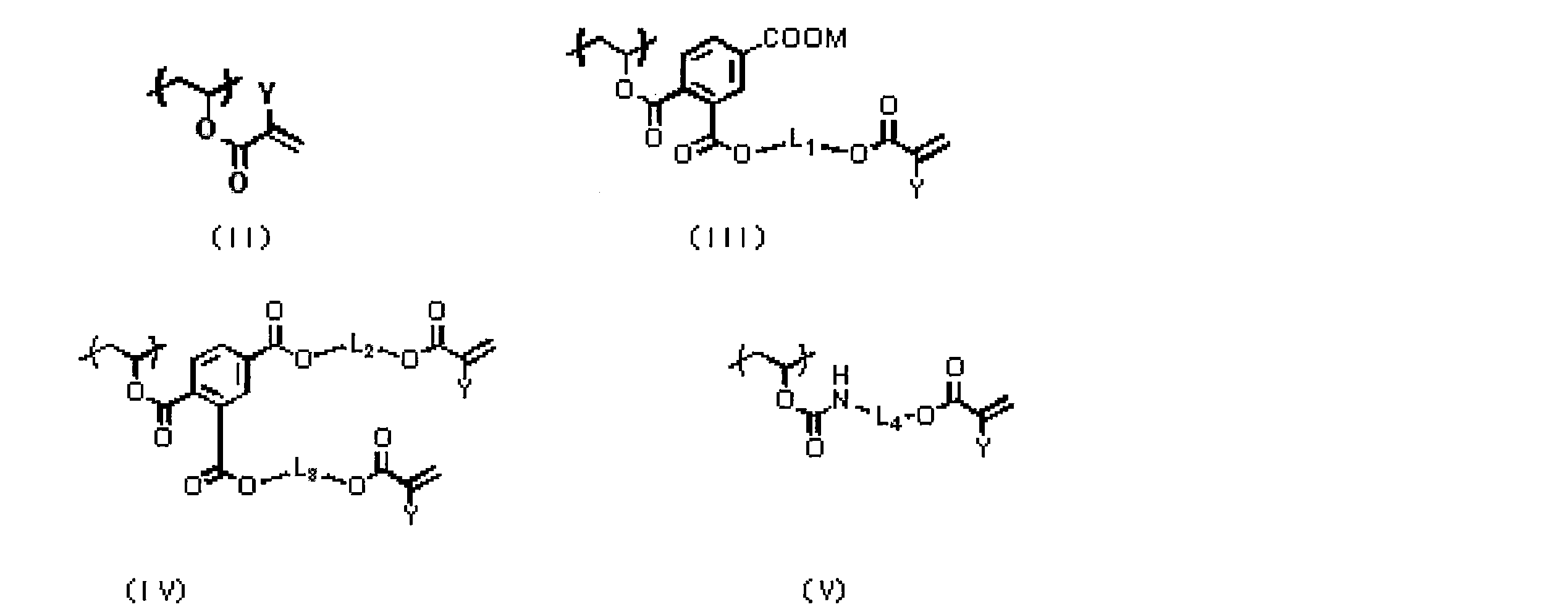
(上記式中、Yは、それぞれ、水素原子またはメチル基を表し、Mは水素原子、リチウム原子、ナトリウム原子またはカリウム原子を表し、L1~L4は、それぞれ、置換基を有していても良いアルキル基、アルキレン基、または、アリール基を表す。)
<3>前記(A)重合性化合物が、ウレタン結合を有する<1>または<2>に記載の平版印刷版原版。
<4>前記(A)重合性化合物が、さらにウレア結合を有する<1>~<3>のいずれかに記載の平版印刷版原版。
<5>前記(A)重合性化合物が、ウレタンを結合および/またはウレア結合を有する(メタ)アクリレートである、<1>または<2>に記載の平版印刷版原版。
<6>前記(A)重合性化合物が、多官能化合物である、<1>~<5>のいずれかに記載の平版印刷版原版。
<7>前記(A)重合性化合物の少なくとも1種が下記で表される化合物である、<1>または<2>に記載の平版印刷版原版。
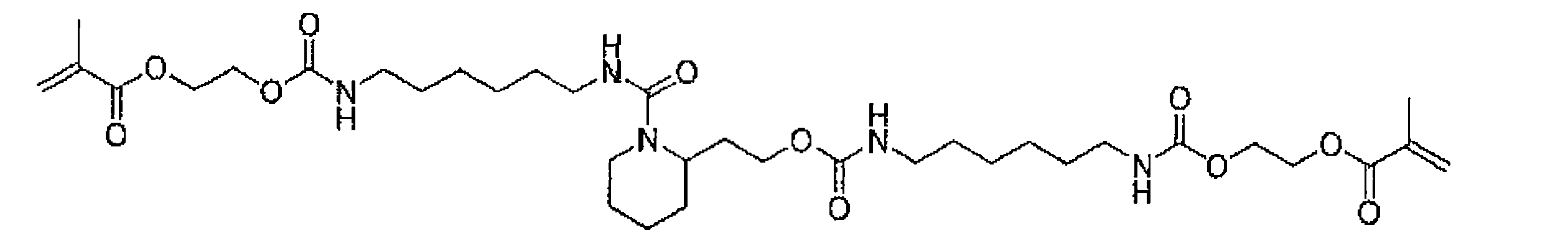
<8>前記ポリビニルアセタールバインダーが、一般式(I-c)、一般式(I-b)および一般式(I-a)で表される繰り返し単位の少なくとも1種と、下記繰り返し単位(1)~(3)と、酸基とを含むポリビニルアセタールバインダーである、<1>~<7>のいずれかに記載の平版印刷版原版。

<9><1>~<8>のいずれかに記載の平版印刷版原版を、画像様に露光する工程と、露光した前記平版印刷版原版を、pHが2~14の現像液の存在下で、非露光部の前記感光層を除去する工程を含むことを特徴とする平版印刷版の製造方法。
<10>前記露光工程で、露光後に前駆体を予備加熱装置内で80℃以上の温度で加熱することを特徴とする、<9>に記載の平版印刷版の製造方法。
<11>前記現像工程において、さらに界面活性剤を含有する前記現像液の存在下、非露光部の感光層と前記保護層とを同時に除去する工程を含む(但し、水洗工程を含まない)、ことを特徴とする<9>または<10>に記載の平版印刷版の製造方法。
<12>前記現像液のpHを、2.0~10.0に制御する工程を含むことを特徴とする、<9>~<11>のいずれかに記載の平版印刷版の製造方法。
<13><1>~<8>のいずれかに記載の平版印刷版原版を、画像様に露光する工程と、印刷機上で印刷インキと湿し水を供給して非露光部の前記感光層を除去する工程とを含むことを特徴とする平版印刷版の製造方法。
<1>支持体上に光重合性層を有し、該光重合性層が、(A)重合性化合物、(B)重合開始剤、(C)一般式(I-c)、一般式(I-b)および一般式(I-a)で表される繰り返し単位の少なくとも1種を有するポリビニルアセタールバインダー、ならびに(D)アクリル樹脂を含むバインダーを含む平版印刷版原版。
<2>前記(C)バインダーが、下記一般式(II)、一般式(III)、一般式(IV)および一般式(V)のいずれかで表される繰り返し単位の少なくとも1種を有するポリビニルアセタールバインダーである、<1>に記載の平版印刷版原版。
<3>前記(A)重合性化合物が、ウレタン結合を有する<1>または<2>に記載の平版印刷版原版。
<4>前記(A)重合性化合物が、さらにウレア結合を有する<1>~<3>のいずれかに記載の平版印刷版原版。
<5>前記(A)重合性化合物が、ウレタンを結合および/またはウレア結合を有する(メタ)アクリレートである、<1>または<2>に記載の平版印刷版原版。
<6>前記(A)重合性化合物が、多官能化合物である、<1>~<5>のいずれかに記載の平版印刷版原版。
<7>前記(A)重合性化合物の少なくとも1種が下記で表される化合物である、<1>または<2>に記載の平版印刷版原版。
<10>前記露光工程で、露光後に前駆体を予備加熱装置内で80℃以上の温度で加熱することを特徴とする、<9>に記載の平版印刷版の製造方法。
<11>前記現像工程において、さらに界面活性剤を含有する前記現像液の存在下、非露光部の感光層と前記保護層とを同時に除去する工程を含む(但し、水洗工程を含まない)、ことを特徴とする<9>または<10>に記載の平版印刷版の製造方法。
<12>前記現像液のpHを、2.0~10.0に制御する工程を含むことを特徴とする、<9>~<11>のいずれかに記載の平版印刷版の製造方法。
<13><1>~<8>のいずれかに記載の平版印刷版原版を、画像様に露光する工程と、印刷機上で印刷インキと湿し水を供給して非露光部の前記感光層を除去する工程とを含むことを特徴とする平版印刷版の製造方法。
本発明の構成によれば、現像液のランニング性に優れ、広い水幅を持ち、かつ耐刷性に優れた平版印刷版を提供できる平版印刷版原版および平版印刷版の製造方法を提供することができる。
以下において、本発明の内容について詳細に説明する。以下に記載する構成要件の説明は、本発明の代表的な実施態様に基づいてなされることがあるが、本発明はそのような実施態様に限定されるものではない。尚、本願明細書において「~」とはその前後に記載される数値を下限値および上限値として含む意味で使用される。
本明細書中、一般式で表される化合物における基の表記に関して、置換あるいは無置換を記していない場合、当該基がさらに置換基を有することが可能な場合には、他に特に規定がない限り、無置換の基のみならず置換基を有する基も包含する。例えば、一般式において、「Rはアルキル基、アリール基または複素環基を表す」との記載があれば、「Rは無置換アルキル基、置換アルキル基、無置換アリール基、置換アリール基、無置換複素環基または置換複素環基を表す」ことを意味する。また、本明細書中、(メタ)アクリルは、アクリルとメタクリルを共に含む概念を表す。
本明細書中、一般式で表される化合物における基の表記に関して、置換あるいは無置換を記していない場合、当該基がさらに置換基を有することが可能な場合には、他に特に規定がない限り、無置換の基のみならず置換基を有する基も包含する。例えば、一般式において、「Rはアルキル基、アリール基または複素環基を表す」との記載があれば、「Rは無置換アルキル基、置換アルキル基、無置換アリール基、置換アリール基、無置換複素環基または置換複素環基を表す」ことを意味する。また、本明細書中、(メタ)アクリルは、アクリルとメタクリルを共に含む概念を表す。
[平版印刷版原版]
以下、本発明の平版印刷版原版について詳細に説明する。本発明の平版印刷版原版は、支持体上に光重合性層を有し、該光重合性層が、(A)重合性化合物、(B)重合開始剤、(C)一般式(I-c)、一般式(I-b)および一般式(I-a)で表される繰り返し単位の少なくとも1種を有するポリビニルアセタールバインダー(以下、「特定ポリビニルアセタールバインダー」ということがある)、ならびに(D)アクリル樹脂を含むバインダーを含むことを特徴とする。

(上記式中、Xは、それぞれ、水素原子またはメチル基を表し、Lは、それぞれ、2価の連結基を表す。)
以下、本発明の平版印刷版原版について詳細に説明する。本発明の平版印刷版原版は、支持体上に光重合性層を有し、該光重合性層が、(A)重合性化合物、(B)重合開始剤、(C)一般式(I-c)、一般式(I-b)および一般式(I-a)で表される繰り返し単位の少なくとも1種を有するポリビニルアセタールバインダー(以下、「特定ポリビニルアセタールバインダー」ということがある)、ならびに(D)アクリル樹脂を含むバインダーを含むことを特徴とする。
本発明の平板印刷版原版は、コンピューター等のデジタル信号から各種レーザーを用いて直接製版できる、いわゆるダイレクト製版可能であることが好ましい。また、特に、pH2.0~10.0以下の水溶液や印刷機上においても現像可能であることが好ましい。
以下、本発明の平版印刷版原版の好ましい態様について詳細に説明する。
本発明の平版印刷版原版は、支持体と、該支持体上に設けられた感光層を含む。さらに、本発明の平版印刷版原版は、前記支持体と前記感光層との間に、中間層としての下塗り層が設けられていても良い。さらに、本発明の平版印刷版原版は、他の構成層を有していてもよい。本発明では、支持体と中間層が互いに接していることが好ましく、支持体と、中間層と、感光層が該順に互いに接していることがより好ましい。しかしながら、本発明の趣旨を逸脱しない範囲で、支持体と中間層の間、中間層と感光層の間に、さらに中間層(下塗り層)が設けられていてもよい。本発明の平版印刷版原版は、前記感光層の前記支持体とは反対側の表面上に、保護層を含むことが好ましい。また、本発明の平版印刷版原版は、必要に応じて、支持体の裏面にバックコート層を設けることができる。
以下、本発明の平版印刷版原版を構成する支持体、中間層、感光層、その他の層、保護層、バックコート層について順に説明し、本発明の平版印刷版原版を形成する方法を説明する。
〔支持体〕
本発明の平版印刷版原版に用いられる支持体は、特に限定されず、寸度的に安定な板状な親水性支持体であればよい。特に、アルミニウム支持体が好ましい。
アルミニウム支持体の中でも、粗面化処理、陽極酸化処理等の表面処理を施されたアルミニウム支持体が好ましい。この粗面化処理、陽極酸化処理等の表面処理を施されたアルミニウム支持体の詳細は特表2009-516222号公報、および国際公開第2007/057348号パンフレットに記載されており、参照することができる。
アルミニウム支持体の粗面化処理には酸が使用される。祖面化処理に使用する酸としては、例えば、硝酸、硫酸、塩化水素を含んでなる酸などが挙げられ、好ましくは塩化水素を含んでなる酸である。また、例えば、塩化水素および酢酸の混合物も使用できる。
一方、電気化学的な粗面化処理、および電極電圧のような陽極酸化のパラメーターの間の関係は、酸電解質の性質と濃度、または消費電力、一方でRaおよび陽極の重量(アルミニウム表面上で生成するAl2O3のg/m2)から平版の性質を得ることはすでに知られており、より詳細は、例えばATB Metallurgie Journal,volume 42 nr.1-2(2002)pag.69に発表されたF.R.Mayersによる論文“Management of Change in the Aluminium Printing Industry”に見ることができる。
陽極酸化処理が施されたアルミニウム支持体は、いわゆる後陽極酸化処理(post-anodic treatment)にかけ、その表面の親水性の性質を改良してもよい。例えば、アルミニウム支持体の表面を例えば95℃に上昇させた珪酸ナトリウム溶液で処理することにより珪酸で被覆処理するようにしてもよい。或いは、無機弗化物をさらに含有する燐酸塩溶液と共に酸化アルミニウム表面を処理する燐酸塩処理を行ってもよい。さらに、酸化アルミニウム表面をクエン酸またはクエン酸塩溶液に浸漬させてもよい。この処理は室温において行ってもよく、約30~50℃のわずかに高められた温度条件下において行うこともできる。さらに、重炭酸塩溶液とともに酸化アルミニウム表面を浸漬させてもよい。また、酸化アルミニウム表面は、ポリビニルホスホン酸、ポリビニルメチルホスホン酸、ポリビニルアルコールの燐酸エステル類、ポリビニルスルホン酸、ポリビニルベンゼンスルホン酸、ポリビニルアルコールの硫酸エステル類、およびスルホン化された脂肪族アルデヒドとの反応により生成するポリビニルアルコール類のアセタール類によっても処理できる。
後陽極酸化処理は、ポリアクリル酸または少なくとも30mol%のアクリル酸単量体単位を含んでなる重合体、例えばアライド・コロイズ(ALLIED COLLOIDS)から市販されているポリアクリル酸であるGLASCOL E15の溶液を用いても行うことができる。
粗面化処理されて陽極酸化されたアルミニウム支持体は、板のようなシート状材料であってもよく、例えば印刷機の印刷シリンダーの周りを動くスリーブのような円筒状部品であってもよい。
粗面化処理、陽極酸化処理等の表面処理以外に、例えば、機械的粗面化処理、電気化学的粗面化処理(電気化学的に表面を溶解させる粗面化処理)、化学的粗面化処理(化学的に表面を選択溶解させる粗面化処理)を施してもよい。これらの処理については、特開2007-206217号公報の段落番号〔0241〕~〔0245〕に記載された方法を好ましく用いることができる。
支持体は、中心線平均粗さが0.10~1.2μmであるのが好ましい。この範囲内で、感光層との良好な密着性、良好な耐刷性と良好な汚れ難さが得られる。
また、支持体の色濃度としては、反射濃度値として0.15~0.65であるのが好ましい。この範囲内で、画像露光時のハレーション防止による良好な画像形成性と現像後の良好な検版性が得られる。
支持体の厚さは0.1~0.6mmであるのが好ましく、0.15~0.4mmであるのがより好ましく、0.2~0.3mmであるのが更に好ましい。
また、支持体の色濃度としては、反射濃度値として0.15~0.65であるのが好ましい。この範囲内で、画像露光時のハレーション防止による良好な画像形成性と現像後の良好な検版性が得られる。
支持体の厚さは0.1~0.6mmであるのが好ましく、0.15~0.4mmであるのがより好ましく、0.2~0.3mmであるのが更に好ましい。
支持体は、親水性層(以下、ベース層ともいう)を有する柔軟性支持体であってもよい。柔軟性支持体は、例えば、紙、プラスチックフィルムまたはアルミニウムなどが挙げられる。プラスチックフィルムの好ましい例としては、ポリエチレンテレフタレートフィルム、ポリエチレンナフタレートフィルム、酢酸セルロースフィルム、ポリスチレンフィルム、ポリカーボネートフィルムなどが挙げられ、プラスチックフィルム支持体は不透明であってもよく、透明であってもよい。
ベース層は、好ましくは硬化剤、例えばホルムアルデヒド、グリオキサル、ポリイソシアネートまたは加水分解されたテトラ-アルキルオルト珪酸エステルで架橋結合された親水性結合剤から得られる架橋結合された親水性層である。後者が特に好ましい。親水性ベース層の厚さは0.2~25μmの範囲内で変動することができ、好ましくは1~10μmである。ベース層の好ましい態様のさらなる詳細は例えば欧州特許出願公開第1025992号明細書に見ることができる。
〔支持体親水化処理、下塗り層〕
本発明の平版印刷版原版においては、非画像部領域の親水性を向上させ印刷汚れを防止するために、支持体表面の親水化処理を行ったり、支持体と感光層との間に下塗り層を設けたりすることも好適である。
本発明の平版印刷版原版においては、非画像部領域の親水性を向上させ印刷汚れを防止するために、支持体表面の親水化処理を行ったり、支持体と感光層との間に下塗り層を設けたりすることも好適である。
支持体表面の親水化処理としては、支持体をケイ酸ナトリウム等の水溶液に浸漬処理または電解処理するアルカリ金属シリケート処理、フッ化ジルコン酸カリウムで処理する方法、リン酸基を含んだポリマー、ポリビニルホスホン酸で処理する方法等が挙げられるが、ポリビニルホスホン酸水溶液に浸漬処理する方法が好ましく用いられる。
下塗り層としては、ホスホン酸、リン酸、スルホン酸などの酸基を有する化合物を有する下塗り層が好ましく用いられる。これらの化合物は、感光層との密着性を向上させる為に、さらに重合性基を含有することが好ましい。さらにエチレンオキシド基などの親水性付与基を有する化合物も好適な化合物として挙げることができる。
これらの化合物は低分子でも高分子ポリマーであってもよい。特開平10-282679号公報に記載されている付加重合可能なエチレン性二重結合反応基を有しているシランカップリング剤、特開平2-304441号公報記載のエチレン性二重結合反応基を有しているリン化合物などが好適に挙げられる。
最も好ましい下塗り層としては、特開2005-238816、特開2005-125749、特開2006-239867、特開2006-215263公報記載の架橋性基(好ましくは、エチレン性不飽和結合基)、支持体表面に相互作用する官能基および親水性基を有する低分子又は高分子化合物を含有するものが挙げられる。
これらの化合物は低分子でも高分子ポリマーであってもよい。特開平10-282679号公報に記載されている付加重合可能なエチレン性二重結合反応基を有しているシランカップリング剤、特開平2-304441号公報記載のエチレン性二重結合反応基を有しているリン化合物などが好適に挙げられる。
最も好ましい下塗り層としては、特開2005-238816、特開2005-125749、特開2006-239867、特開2006-215263公報記載の架橋性基(好ましくは、エチレン性不飽和結合基)、支持体表面に相互作用する官能基および親水性基を有する低分子又は高分子化合物を含有するものが挙げられる。
下塗り層の塗布量は、0.001~1.5g/m2が好ましく、より好ましくは0.003~1.0g/m2、さらに好ましくは0.005~0.7g/m2であることが好ましい。
<中間層の形成方法>
中間層は、水又はメタノール、エタノール、メチルエチルケトンなどの有機溶剤若しくはそれらの混合溶剤に上記化合物を溶解させた溶液を支持体上に塗布、乾燥する方法、又は、水、あるいは、メタノール、エタノール、メチルエチルケトンなどの有機溶剤若しくはそれらの混合溶剤に上記化合物を溶解させた溶液に、支持体を浸漬して上記化合物を吸着させ、しかる後、水などによって洗浄、乾燥する方法によって設けることができる。前者の方法では、上記化合物の濃度0.005~10質量%の溶液を種々の方法で塗布できる。例えば、バーコーター塗布、回転塗布、スプレー塗布、カーテン塗布などいずれの方法を用いてもよい。また、後者の方法では、溶液の濃度は0.01~20質量%、好ましくは0.05~5質量%であり、浸漬温度は20~90℃、好ましくは25~50℃であり、浸漬時間は0.1秒~20分、好ましくは2秒~1分である。
中間層は、水又はメタノール、エタノール、メチルエチルケトンなどの有機溶剤若しくはそれらの混合溶剤に上記化合物を溶解させた溶液を支持体上に塗布、乾燥する方法、又は、水、あるいは、メタノール、エタノール、メチルエチルケトンなどの有機溶剤若しくはそれらの混合溶剤に上記化合物を溶解させた溶液に、支持体を浸漬して上記化合物を吸着させ、しかる後、水などによって洗浄、乾燥する方法によって設けることができる。前者の方法では、上記化合物の濃度0.005~10質量%の溶液を種々の方法で塗布できる。例えば、バーコーター塗布、回転塗布、スプレー塗布、カーテン塗布などいずれの方法を用いてもよい。また、後者の方法では、溶液の濃度は0.01~20質量%、好ましくは0.05~5質量%であり、浸漬温度は20~90℃、好ましくは25~50℃であり、浸漬時間は0.1秒~20分、好ましくは2秒~1分である。
〔バックコート層〕
支持体に表面処理を施した後または下塗り層を形成させた後、必要に応じて、支持体の裏面にバックコート層を設けることができる。
バックコート層としては、例えば、特開平5-45885号公報に記載されている有機高分子化合物、特開平6-35174号公報に記載されている有機金属化合物または無機金属化合物を加水分解および重縮合させて得られる金属酸化物からなる被覆層が好適に挙げられる。中でも、Si(OCH3)4、Si(OC2H5)4、Si(OC3H7)4、Si(OC4H9)4等のケイ素のアルコキシ化合物を用いるのが、原料が安価で入手しやすい点で好ましい。
支持体に表面処理を施した後または下塗り層を形成させた後、必要に応じて、支持体の裏面にバックコート層を設けることができる。
バックコート層としては、例えば、特開平5-45885号公報に記載されている有機高分子化合物、特開平6-35174号公報に記載されている有機金属化合物または無機金属化合物を加水分解および重縮合させて得られる金属酸化物からなる被覆層が好適に挙げられる。中でも、Si(OCH3)4、Si(OC2H5)4、Si(OC3H7)4、Si(OC4H9)4等のケイ素のアルコキシ化合物を用いるのが、原料が安価で入手しやすい点で好ましい。
<感光層>
本発明における感光層は、(A)重合性化合物、(B)重合開始剤、(C)特定ポリビニルアセタールバインダー、(D)アクリル樹脂バインダーを有する。また(E)増感剤、(F)着色剤を有していても良い。またこれら以外のその他感光層成分を有していても良い。
本発明における感光層は、(A)重合性化合物、(B)重合開始剤、(C)特定ポリビニルアセタールバインダー、(D)アクリル樹脂バインダーを有する。また(E)増感剤、(F)着色剤を有していても良い。またこれら以外のその他感光層成分を有していても良い。
<(A)重合性化合物>
本発明における感光層に用いる重合性化合物は、少なくとも一個のエチレン性不飽和二重結合を有する付加重合性化合物であり、末端エチレン性不飽和結合を少なくとも1個、好ましくは2個以上有する化合物から選ばれる。これらは、例えばモノマー、プレポリマー、すなわち2量体、3量体およびオリゴマー、またはそれらの混合物などの化学的形態をもつ。モノマーの例としては、不飽和カルボン酸(例えば、アクリル酸、メタクリル酸、イタコン酸、クロトン酸、イソクロトン酸、マレイン酸など)や、そのエステル類、アミド類が挙げられ、好ましくは、不飽和カルボン酸と多価アルコール化合物とのエステル、不飽和カルボン酸と多価アミン化合物とのアミド類が用いられる。また、ヒドロキシル基やアミノ基、メルカプト基等の求核性置換基を有する不飽和カルボン酸エステル或いはアミド類と単官能もしくは多官能イソシアネート類或いはエポキシ類との付加反応物、および単官能もしくは、多官能のカルボン酸との脱水縮合反応物等も好適に使用される。また、イソシアネート基や、エポキシ基等の親電子性置換基を有する不飽和カルボン酸エステル或いはアミド類と単官能もしくは多官能のアルコール類、アミン類、チオール類との付加反応物、更にハロゲン基や、トシルオキシ基等の脱離性置換基を有する不飽和カルボン酸エステル或いはアミド類と単官能もしくは多官能のアルコール類、アミン類、チオール類との置換反応物も好適である。また、別の例として、上記の不飽和カルボン酸の代わりに、不飽和ホスホン酸、スチレン、ビニルエーテル等に置き換えた化合物群を使用することも可能である。
本発明における感光層に用いる重合性化合物は、少なくとも一個のエチレン性不飽和二重結合を有する付加重合性化合物であり、末端エチレン性不飽和結合を少なくとも1個、好ましくは2個以上有する化合物から選ばれる。これらは、例えばモノマー、プレポリマー、すなわち2量体、3量体およびオリゴマー、またはそれらの混合物などの化学的形態をもつ。モノマーの例としては、不飽和カルボン酸(例えば、アクリル酸、メタクリル酸、イタコン酸、クロトン酸、イソクロトン酸、マレイン酸など)や、そのエステル類、アミド類が挙げられ、好ましくは、不飽和カルボン酸と多価アルコール化合物とのエステル、不飽和カルボン酸と多価アミン化合物とのアミド類が用いられる。また、ヒドロキシル基やアミノ基、メルカプト基等の求核性置換基を有する不飽和カルボン酸エステル或いはアミド類と単官能もしくは多官能イソシアネート類或いはエポキシ類との付加反応物、および単官能もしくは、多官能のカルボン酸との脱水縮合反応物等も好適に使用される。また、イソシアネート基や、エポキシ基等の親電子性置換基を有する不飽和カルボン酸エステル或いはアミド類と単官能もしくは多官能のアルコール類、アミン類、チオール類との付加反応物、更にハロゲン基や、トシルオキシ基等の脱離性置換基を有する不飽和カルボン酸エステル或いはアミド類と単官能もしくは多官能のアルコール類、アミン類、チオール類との置換反応物も好適である。また、別の例として、上記の不飽和カルボン酸の代わりに、不飽和ホスホン酸、スチレン、ビニルエーテル等に置き換えた化合物群を使用することも可能である。
多価アルコール化合物と不飽和カルボン酸とのエステルのモノマーの具体例としては、アクリル酸エステルとして、エチレングリコールジアクリレート、1,3-ブタンジオールジアクリレート、テトラメチレングリコールジアクリレート、プロピレングリコールジアクリレート、トリメチロールプロパントリアクリレート、ヘキサンジオールジアクリレート、テトラエチレングリコールジアクリレート、ペンタエリスリトールテトラアクリレート、ソルビトールトリアクリレート、イソシアヌール酸エチレンオキシド(EO)変性トリアクリレート、ポリエステルアクリレートオリゴマー等がある。メタクリル酸エステルとしては、テトラメチレングリコールジメタクリレート、ネオペンチルグリコールジメタクリレート、トリメチロールプロパントリメタクリレート、エチレングリコールジメタクリレート、ペンタエリスリトールトリメタクリレート、ビス〔p-(3-メタクリルオキシ-2-ヒドロキシプロポキシ)フェニル〕ジメチルメタン、ビス-〔p-(メタクリルオキシエトキシ)フェニル〕ジメチルメタン等がある。また、多価アミン化合物と不飽和カルボン酸とのアミドのモノマーの具体例としては、メチレンビス-アクリルアミド、メチレンビス-メタクリルアミド、1,6-ヘキサメチレンビス-アクリルアミド、1,6-ヘキサメチレンビス-メタクリルアミド、ジエチレントリアミントリスアクリルアミド、キシリレンビスアクリルアミド、キシリレンビスメタクリルアミド等がある。
また、イソシアネートと水酸基の付加反応を用いて製造されるウレタン系付加重合性化合物も好適であり、そのようなウレタン構造を有する化合物の具体例としては、例えば、特公昭48-41708号公報に記載されている1分子に2個以上のイソシアネート基を有するポリイソシアネート化合物に、下記一般式(A)で示される水酸基を含有するビニルモノマーを付加させた1分子中に2個以上の重合性ビニル基を含有するビニルウレタン化合物等が挙げられる。
CH2=C(R4)COOCH2CH(R5)OH (A)
(ただし、R4およびR5は、HまたはCH3を示す。)
(ただし、R4およびR5は、HまたはCH3を示す。)
また、特開昭51-37193号公報、特公平2-32293号公報、特公平2-16765号公報に記載されているようなウレタンアクリレート類や、特公昭58-49860号公報、特公昭56-17654号公報、特公昭62-39417号公報、特公昭62-39418号公報記載のエチレンオキサイド系骨格を有するウレタン化合物類も好適である。
また、特表2007-506125に記載の光-酸化可能な重合性化合物も好適であり、少なくとも1個のウレア基および/または第三級アミノ基を含有する重合可能な化合物が特に好ましい。
本発明では特に、ウレタン結合および/またはウレア結合を有する化合物が好ましく、ウレタン結合および/またはウレア結合を有する(メタ)アクリレートがより好ましい。本発明では、また、多官能の重合性化合物が好ましく、2または3官能の重合性化合物がより好ましい。このような化合物を採用することにより、本発明の効果がより効果的に発揮される傾向にある。
具体的には、下記の化合物が挙げられる。
本発明では特に、ウレタン結合および/またはウレア結合を有する化合物が好ましく、ウレタン結合および/またはウレア結合を有する(メタ)アクリレートがより好ましい。本発明では、また、多官能の重合性化合物が好ましく、2または3官能の重合性化合物がより好ましい。このような化合物を採用することにより、本発明の効果がより効果的に発揮される傾向にある。
具体的には、下記の化合物が挙げられる。
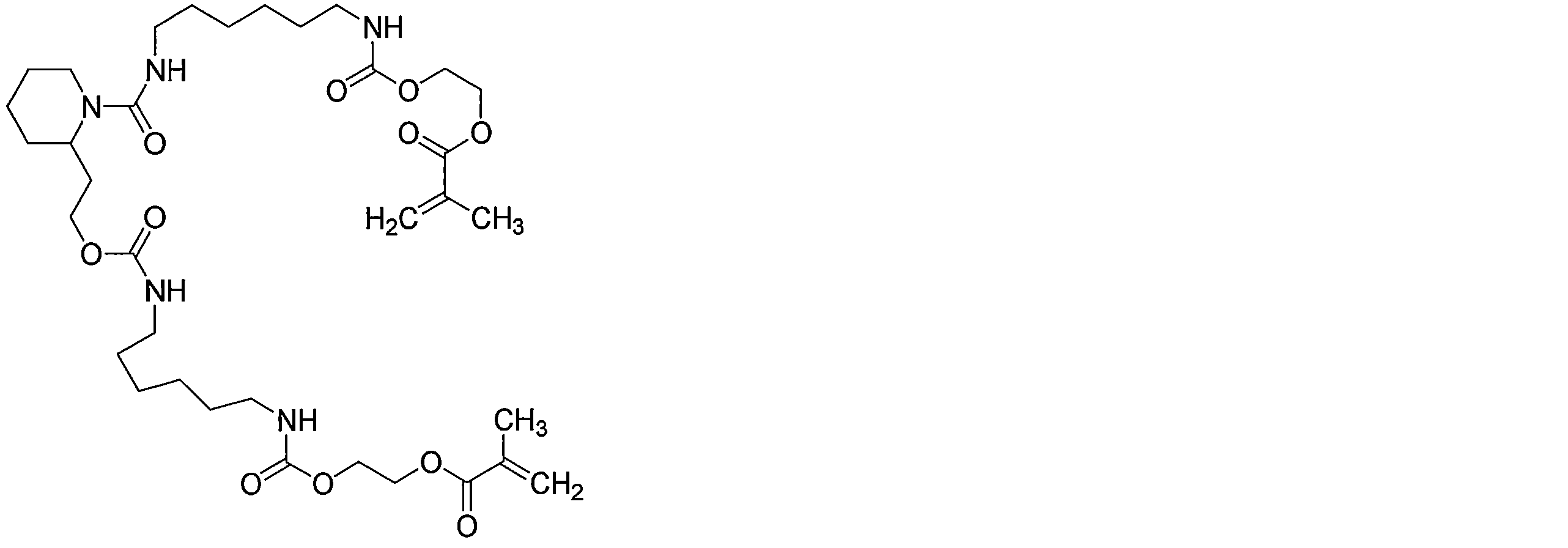
これらの重合性化合物の構造、単独使用か併用か、添加量等の使用方法の詳細は、最終的な平版印刷版原版の性能設計にあわせて任意に設定できるが、1つの態様として、ウレタン結合を有する化合物と、ウレア結合を有する化合物の併用が例示される。上記の重合性化合物は、感光層の全固形分に対して、好ましくは5~75重量%、より好ましくは25~70重量%、さらに好ましくは30~60重量%の範囲で使用される。
<(B)重合開始剤>
本発明の感光層は重合開始剤(以下、開始剤化合物とも称する)を含有することが好ましい。本発明においては、ラジカル重合開始剤が好ましく用いられる。
本発明の感光層は重合開始剤(以下、開始剤化合物とも称する)を含有することが好ましい。本発明においては、ラジカル重合開始剤が好ましく用いられる。
本発明における開始剤化合物としては、当業者間で公知のものを制限なく使用でき、具体的には、例えば、トリハロメチル化合物、カルボニル化合物、有機過酸化物、アゾ系化合物、アジド化合物、メタロセン化合物、ヘキサアリールビイミダゾール化合物、有機ホウ素化合物、ジスルホン化合物、オキシムエステル化合物、オニウム塩化合物、鉄アレーン錯体が挙げられる。なかでも、ヘキサアリールビイミダゾール系化合物、オニウム塩、トリハロメチル化合物およびメタロセン化合物からなる群より選択される少なくとも1種であることが好ましく、特にヘキサアリールビイミダゾール系化合物が好ましい。上記の重合開始剤は、2種以上を適宜併用することもできる。
ヘキサアリールビイミダゾール系化合物としては、特公昭45-37377号、特公昭44-86516号、欧州特許24629号、欧州特許107792号、米国特許4、410、621号の各公報記載のロフィンダイマー類、例えば2,2′-ビス(o-クロロフェニル)-4,4′,5,5′-テトラフェニルビイミダゾール、2,2′-ビス(o-ブロモフェニル)-4,4′,5,5′-テトラフェニルビイミダゾール、2,2′-ビス(o,p-ジクロロフェニル)-4,4′,5,5′-テトラフェニルビイミダゾール、2,2′-ビス(o-クロロフェニル)-4,4′,5,5′-テトラ(m-メトキシフェニル)ビイミダゾール、2,2′-ビス(o,o′-ジクロロフェニル)-4,4′,5,5′-テトラフェニルビイミダゾール、2,2′-ビス(o-ニトロフェニル)-4,4′,5,5′-テトラフェニルビイミダゾール、2,2′-ビス(o-メチルフェニル)-4,4′,5,5′-テトラフェニルビイミダゾール、2,2′-ビス(o-トリフルオロフェニル)-4,4′,5,5′-テトラフェニルビイミダゾール等が挙げられる。
ヘキサアリールビイミダゾール系化合物は、300~450nmに極大吸収を有する増感色素と併用して用いられることが特に好ましい。
ヘキサアリールビイミダゾール系化合物は、300~450nmに極大吸収を有する増感色素と併用して用いられることが特に好ましい。
本発明において好適に用いられるオニウム塩は、スルホニウム塩、ヨードニウム塩、ジアゾニウム塩が好ましく用いられる。特にジアリールヨードニウム塩、トリアリールスルホニウム塩が好ましく用いられる。オニウム塩は、750~1400nmに極大吸収を有する赤外線吸収剤と併用して用いられることが特に好ましい。
前記オニウム塩として、特開2012-031400号公報の段落番号0049の記載を参酌できる。
より好ましいものとして、ヨードニウム塩、スルホニウム塩及びアジニウム塩が挙げられる。以下に、これらの化合物の具体例を示すが、これに限定されない。
より好ましいものとして、ヨードニウム塩、スルホニウム塩及びアジニウム塩が挙げられる。以下に、これらの化合物の具体例を示すが、これに限定されない。
前記ヨードニウム塩の例としては、ジフェニルヨードニウム塩が好ましく、特に電子供与性基、例えばアルキル基またはアルコキシル基で置換されたジフェニルヨードニウム塩が好ましく、さらに好ましくは非対称のジフェニルヨードニウム塩が好ましい。具体例としては、ジフェニルヨードニウム=ヘキサフルオロホスファート、4-メトキシフェニル-4-(2-メチルプロピル)フェニルヨードニウム=ヘキサフルオロホスファート、4-(2-メチルプロピル)フェニル-p-トリルヨードニウム=ヘキサフルオロホスファート、4-ヘキシルオキシフェニル-2,4,6-トリメトキシフェニルヨードニウム=ヘキサフルオロホスファート、4-ヘキシルオキシフェニル-2,4-ジエトキシフェニルヨードニウム=テトラフルオロボラート、4-オクチルオキシフェニル-2,4,6-トリメトキシフェニルヨードニウム=1-ペルフルオロブタンスルホナート、4-オクチルオキシフェニル-2,4,6-トリメトキシフェニルヨードニウム=ヘキサフルオロホスファート、ビス(4-t-ブチルフェニル)ヨードニウム=テトラフェニルボラートが挙げられる。
前記スルホニウム塩の例としては、トリフェニルスルホニウム=ヘキサフルオロホスファート、トリフェニルスルホニウム=ベンゾイルホルマート、ビス(4-クロロフェニル)フェニルスルホニウム=ベンゾイルホルマート、ビス(4-クロロフェニル)-4-メチルフェニルスルホニウム=テトラフルオロボラート、トリス(4-クロロフェニル)スルホニウム=3,5-ビス(メトキシカルボニル)ベンゼンスルホナート、トリス(4-クロロフェニル)スルホニウム=ヘキサフルオロホスファートが挙げられる。
前記アジニウム塩の例としては、1-シクロヘキシルメチルオキシピリジニウム=ヘキサフルオロホスファート、1-シクロヘキシルオキシ-4-フェニルピリジニウム=ヘキサフルオロホスファート、1-エトキシ-4-フェニルピリジニウム=ヘキサフルオロホスファート、1-(2-エチルヘキシルオキシ)-4-フェニルピリジニウム=ヘキサフルオロホスファート、4-クロロ-1-シクロヘキシルメチルオキシピリジニウム=ヘキサフルオロホスファート、1-エトキシ-4-シアノピリジニウム=ヘキサフルオロホスファート、3,4-ジクロロ-1-(2-エチルヘキシルオキシ)ピリジニウム=ヘキサフルオロホスファート、1-ベンジルオキシ-4-フェニルピリジニウム=ヘキサフルオロホスファート、1-フェネチルオキシ-4-フェニルピリジニウム=ヘキサフルオロホスファート、1-(2-エチルヘキシルオキシ)-4-フェニルピリジニウム=p-トルエンスルホナート、1-(2-エチルヘキシルオキシ)-4-フェニルピリジニウム=ペルフルオロブタンスルホナート、1-(2-エチルヘキシルオキシ)-4-フェニルピリジニウム=ブロミド、1-(2-エチルヘキシルオキシ)-4-フェニルピリジニウム=テトラフルオロボラートが挙げられる。
これらオニウム塩は、750~1400nmの波長域に極大吸収を有する赤外線吸収剤と併用して用いられることが特に好ましい。
これらオニウム塩は、750~1400nmの波長域に極大吸収を有する赤外線吸収剤と併用して用いられることが特に好ましい。
その他の重合開始剤としては、特開2007-206217号公報段落番号0071~0129に記載の重合開始剤を好ましく用いることができる。
本発明における重合開始剤は単独もしくは2種以上の併用によって好適に用いられる。
本発明における感光層中の重合開始剤の使用量は感光層全固形分の重量に対し、好ましくは0.01~20重量%、より好ましくは0.1~15重量%である。さらに好ましくは1.0重量%~10重量%である。
本発明における感光層中の重合開始剤の使用量は感光層全固形分の重量に対し、好ましくは0.01~20重量%、より好ましくは0.1~15重量%である。さらに好ましくは1.0重量%~10重量%である。
<(C)一般式(I-c)、一般式(I-b)および一般式(I-a)で表される繰り返し単位の少なくとも1種を有するポリビニルアセタールを含むバインダー>
本発明における特定ポリビニルアセタールバインダーは、少なくとも、ビニルアセタールの繰り返し単位と、一般式(I-c)、一般式(I-b)および一般式(I-a)で表される繰り返し単位の少なくとも1種を有することを特徴とする。本発明で用いるポリビニルアセタールはポリビニルブチラールであることが好ましい。
このような特定ポリビニルアセタールバインダーは、例えば、ポリ酢酸ビニルを一部又は全てを鹸化して得られるポリビニルアルコールとアルデヒドを酸性条件下で反応(アセタール化反応)させて合成されたポリビニルアセタールを変性させることで一般式(I-c)、一般式(I-b)および一般式(I-a)で表される繰り返し単位の少なくとも1種を導入したポリマーである。アセタール化に用いられるアルデヒドとしては,ブチルアルデヒドが最も好ましい。

一般式(I-c)、一般式(I-b)および一般式(I-a)で表される繰り返し単位は、一般式(I-b)または(I-c)で表される繰り返し単位が好ましく、一般式(I-c)で表される繰り返し単位がさらに好ましい。
一般式(I-c)、一般式(I-b)および一般式(I-a)で表される繰り返し単位は、下記一般式(II)~(V)のいずれかで表されることが好ましく、一般式(III)~(V)のいずれかで表されることがより好ましく、一般式(III)~(V)のいずれかで表されることがさらに好ましい。
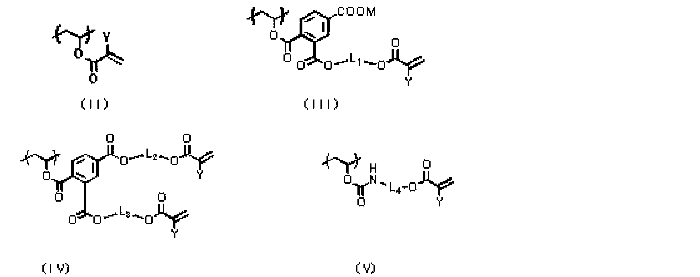
Yは水素原子が好ましい。
L1~L4は、それぞれ、アルキル基が好ましく、炭素数1~6のアルキル基がより好ましく、炭素数1~4のアルキル基がさらに好ましく、炭素数2のアルキル基が特に好ましい。L1~L4が有していてもよい置換基としては、水酸基が挙げられる。
本発明における一般式(I-c)、一般式(I-b)および一般式(I-a)で表される繰り返し単位の好適な一例としては、以下の特定単位を有する共重合体が挙げられる。しかしながら、本発明は、これらに限定されるものではないことは言うまでもない。


このうち、特定単位としては、a-1、a-2、c-1、c-2、d-1、d-2、e-1~e4が好ましく、c-1、c-2、d-1、d-2、e-1~4がより好ましく、e-1~4が特に好ましく用いられる。
本発明で用いる特定ポリビニルアセタールバインダーは、一般式(I-c)、一般式(I-b)および一般式(I-a)で表される繰り返し単位を合計で、5~35mol%の割合で含まれることが好ましく、10~25mol%の割合で含まれることがより好ましい。
本発明で用いる特定ポリビニルアセタールバインダーは、上記(1)を、40~90mol%の割合で含まれることが好ましく、55~85mol%の割合で含まれることがより好ましい。
本発明で用いる特定ポリビニルアセタールバインダーは、上記(2)を0~25mol%の割合で含まれることが好ましく、0~10mol%の割合で含まれることがより好ましい。
本発明で用いる特定ポリビニルアセタールバインダーは、上記(3)を1~40mol%の割合で含まれることが好ましく、1~35mol%の割合で含まれることがより好ましい。
発明で用いる特定ポリビニルアセタールバインダーは、酸基を、0~35mol%の割合で含まれることが好ましく、0~25mol%の割合で含まれることがより好ましい。
さらに、本発明の特定ポリビニルアセタールバインダーは、一般式(I-c)、一般式(I-b)および一般式(I-a)で表される繰り返し単位、上記(1)~(3)および酸基以外の繰り返し単位の割合が、20mol%以下であることが好ましく、10mol%以下であることがより好ましい。このような範囲とすることにより、本発明の効果がより効果的に発揮される傾向にある。
本発明で用いる特定ポリビニルアセタールバインダーが有する酸基としては、カルボン酸基、スルホン酸基、ホスホン酸基、リン酸基、スルホンアミド基等が挙げられるが、特にカルボン酸基が好ましく、(メタ)アクリル酸由来の繰り返し単位や、下記一般式(II)で表される繰り返し単位、式(4)で表される繰り返し単位が好ましい。

Ra、Rb、Rc、Rd、Re、Rfの好ましい置換基としては、置換基を有してもよいアルキル基、ハロゲン原子、置換基を有してもよいアリール基が挙げられ、好ましくは、メチル基、エチル基、プロピル基などの直鎖アルキル基、カルボン酸が置換したアルキル基、ハロゲン原子、フェニル基、カルボン酸が置換したフェニル基が挙げられる
RcおよびRd、ReおよびRfは、それぞれ、を形成することができる。RcとReの結合する炭素原子およびRdとRfの結合する炭素原子間の結合は、単結合または二重結合または芳香族性二重結合であり、二重結合または芳香族性二重結合の場合、Rc-RdまたはRe-RfまたはRc-RfまたはRe-Rdはそれぞれ結合して単結合を形成する。
上記カルボン酸基含有単位の好ましい具体例としては、下記の例が挙げられる。

次に、式(4)で表される繰り返し単位について説明する。

上記式において、Rは、COOR1を表し、R1は、Li、NaまたはKを表す。nは、1~5の整数であり、2が好ましい。
R1は、NaまたはKが好ましく、Naがさらに好ましい。
R1は、NaまたはKが好ましく、Naがさらに好ましい。
さらに、特定ポリビニルアセタールバインダーの好適な一例である、酸基を含有するポリマーの酸基は、塩基性化合物で中和されていても良く、特に、アミノ基、アミジン基、グアニジン基等の塩基性窒素を含有する化合物で中和されていることが好ましい。さらに、塩基性窒素を含有する化合物がエチレン性不飽和基を有することも好ましい。具体的な化合物としては、WO2007/057442公報記載の化合物が挙げられる。
特定ポリビニルアセタールバインダーは、重量平均分子量が5000以上であるのが好ましく、1万~30万であるのがより好ましく、1万~10万であるのがさらに好ましい。また、本発明におけるバインダーポリマーは、数平均分子量が1000以上であるのが好ましく、2000~25万であるのがより好ましい。多分散度(重量平均分子量/数平均分子量)は、1.1~10であるのが好ましい。
特定ポリビニルアセタールバインダーは、単独で用いても2種以上を混合して用いてもよい。特定ポリビニルアセタールバインダーの含有量は、良好な画像部の強度と画像形成性の観点から、感光層の全固形分に対して、5~80重量%が好ましく、10~75重量%がより好ましく、10~65重量%であるのが更に好ましい。
<(D)アクリル樹脂>
本発明における感光層は、特定ポリビニルアセタールバインダーに加え、(D)アクリル樹脂バインダーを含む。現像性の観点から、アクリル樹脂バインダーとしては酸基を有するものが好ましい。
本発明における感光層は、特定ポリビニルアセタールバインダーに加え、(D)アクリル樹脂バインダーを含む。現像性の観点から、アクリル樹脂バインダーとしては酸基を有するものが好ましい。
本発明におけるアクリル樹脂の酸基の好適な一例としては酸基としては、カルボン酸基、スルホン酸基、ホスホン酸基、リン酸基、スルホンアミド基等が挙げられるが、特にカルボン酸基が好ましく、(メタ)アクリル酸由来の繰り返し単位や下記一般式(I)で表されるものが好ましく用いられる。
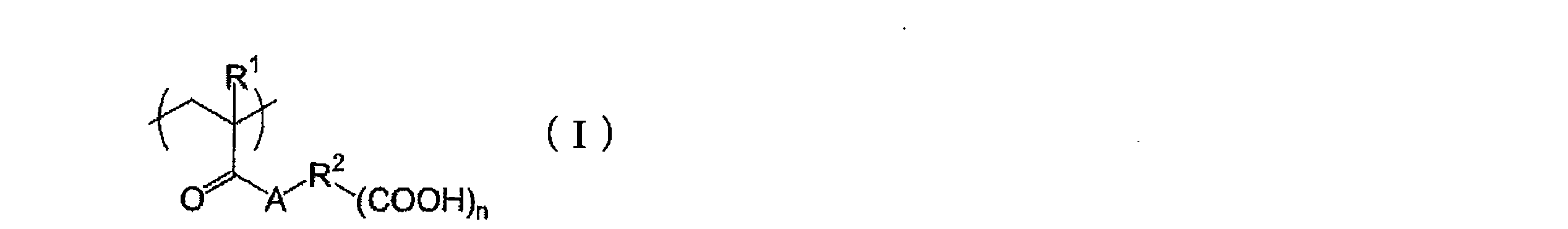
(一般式(I)中、R1は水素原子又はメチル基を表し、R2は単結合又はn+1価の連結基を表す。Aは酸素原子又は-NR3-を表し、R3は水素原子又は炭素数1~10の1価の炭化水素基を表す。nは1~5の整数を表す。)
一般式(I)におけるR2で表される連結基は、水素原子、酸素原子、窒素原子、硫黄原子及びハロゲン原子から構成されるもので、その原子数は好ましくは1~80である。具体的には、アルキレン、置換アルキレン、アリーレン、置換アリーレンなどが挙げられ、これらの2価の基がアミド結合やエステル結合で複数連結された構造を有していてもよい。R2としては、単結合、アルキレン、置換アルキレンであることが好ましく、単結合、炭素数1~5のアルキレン、炭素数1~5の置換アルキレンであることが特に好ましく、単結合、炭素数1~3のアルキレン、炭素数1~3の置換アルキレンであることが最も好ましい。
置換基としては、水素原子を除く1価の非金属原子団を挙げることができ、ハロゲン原子(-F、-Br、-Cl、-I)、ヒドロキシル基、アルコキシ基、アリーロキシ基、メルカプト基、アシル基、カルボキシル基及びその共役塩基基、アルコキシカルボニル基、アリーロキシカルボニル基、カルバモイル基、アリール基、アルケニル基、アルキニル基等が挙げられる。
置換基としては、水素原子を除く1価の非金属原子団を挙げることができ、ハロゲン原子(-F、-Br、-Cl、-I)、ヒドロキシル基、アルコキシ基、アリーロキシ基、メルカプト基、アシル基、カルボキシル基及びその共役塩基基、アルコキシカルボニル基、アリーロキシカルボニル基、カルバモイル基、アリール基、アルケニル基、アルキニル基等が挙げられる。
R3は水素原子又は炭素数1~5の炭化水素基が好ましく、水素原子又は炭素数1~3の炭化水素基が特に好ましく、水素原子又はメチル基が最も好ましい。nは1~3であることが好ましく、1又は2であることが特に好ましく、1であることが最も好ましい。
アクリル樹脂における、全繰り返し単位のうち、カルボン酸基を有する共重合成分の割合(モル%)は、現像性の観点から、1~70%が好ましい。現像性と耐刷性の両立を考慮すると、1~50%がより好ましく、1~30%が特に好ましい。
本発明に用いられるアクリル樹脂はさらに架橋性基を有していても良い。ここで架橋性基とは、平版印刷版原版を露光した際に感光層中で起こるラジカル重合反応の過程でバインダーポリマーを架橋させる基のことである。このような機能の基であれば特に限定されないが、例えば、付加重合反応し得る官能基としてエチレン性不飽和結合基、アミノ基、エポキシ基等が挙げられる。また光照射によりラジカルになり得る官能基であってもよく、そのような架橋性基としては、例えば、チオール基、ハロゲン基等が挙げられる。なかでも、エチレン性不飽和結合基が好ましい。エチレン性不飽和結合基としては、スチリル基、(メタ)アクリロイル基、アリル基が好ましい。
アクリル樹脂は、例えば、その架橋性官能基にフリーラジカル(重合開始ラジカルまたは重合性化合物の重合過程の生長ラジカル)が付加し、ポリマー間で直接にまたは重合性化合物の重合連鎖を介して付加重合して、ポリマー分子間に架橋が形成されて硬化する。または、ポリマー中の原子(例えば、官能性架橋基に隣接する炭素原子上の水素原子)がフリーラジカルにより引き抜かれてポリマーラジカルが生成し、それが互いに結合することによって、ポリマー分子間に架橋が形成されて硬化する。
アクリル樹脂中の架橋性基の含有量(ヨウ素滴定によるラジカル重合可能な不飽和二重結合の含有量)は、バインダーポリマー1g当たり、好ましくは0.01~10.0mmol、より好ましくは0.05~5.0mmol、最も好ましくは0.1~2.0mmolである。
本発明に用いられるアクリル樹脂は、上記酸基を有する重合単位、架橋性基を有する重合単位の他に、(メタ)アクリル酸アルキルまたはアラルキルエステルの重合単位を有していてもよい。(メタ)アクリル酸アルキルエステルのアルキル基は、好ましくは炭素数1~5のアルキル基であり、メチル基がより好ましい。(メタ)アクリル酸アラルキルエステルとしては、(メタ)アクリル酸ベンジル等が挙げられる。
アクリル樹脂は、重量平均分子量が5000以上であるのが好ましく、1万~30万であるのがより好ましく、また、数平均分子量が1000以上であるのが好ましく、2000~25万であるのがより好ましい。多分散度(重量平均分子量/数平均分子量)は、1.1~10であるのが好ましい。
アクリル樹脂は単独で用いても2種以上を混合して用いてもよい。バインダーポリマーの含有量は、良好な画像部の強度と画像形成性の観点から、感光層の全固形分に対して、5~75質量%が好ましく、10~70質量%がより好ましく、10~60質量%であるのが更に好ましい。
アクリル樹脂は単独で用いても2種以上を混合して用いてもよい。バインダーポリマーの含有量は、良好な画像部の強度と画像形成性の観点から、感光層の全固形分に対して、5~75質量%が好ましく、10~70質量%がより好ましく、10~60質量%であるのが更に好ましい。
また、特定ポリアセタールバインダーとアクリル樹脂の重量比は、1:1~6:1であることが好ましく、2:1~4:1であることがより好ましい。このような範囲とすることにより、本発明の効果がより効果的に発揮される傾向にある。
また、本発明におけるバインダー全成分と重合性化合物の合計含有量は、感光層の全固形分に対して、80質量%以下であることが好ましい。80質量%を超えると、感度の低下、現像性の低下を引き起こす場合がある。より好ましくは35~75質量%である。
本発明においては、平版印刷版原版の感光層中の重合性化合物と全バインダーポリマー(例えば、特定ポリアセタールバインダーとアクリル樹脂の合計)の割合を調節することにより、現像液の感光層への浸透性がより向上し、現像性が更に向上する。即ち、感光層中のラジカル重合性化合物/バインダーポリマーの質量比は、1.2以上が好ましく、より好ましくは1.25~4.5、最も好ましくは、2~4である。
<増感色素>
本発明における感光層は、増感色素を含有することが好ましい。増感色素は、画像露光時の光を吸収して励起状態となり、後述する重合開始剤に電子移動、エネルギー移動又は発熱などでエネルギーを供与し、重合開始機能を向上させるものであれば特に限定せず用いることができる。特に、300~450nm又は750~1400nmに極大吸収を有する増感色素が好ましく用いられる。
本発明における感光層は、増感色素を含有することが好ましい。増感色素は、画像露光時の光を吸収して励起状態となり、後述する重合開始剤に電子移動、エネルギー移動又は発熱などでエネルギーを供与し、重合開始機能を向上させるものであれば特に限定せず用いることができる。特に、300~450nm又は750~1400nmに極大吸収を有する増感色素が好ましく用いられる。
350~450nmの波長域に極大吸収を有する増感色素としては、メロシアニン色素類、ベンゾピラン類、クマリン類、芳香族ケトン類、アントラセン類等を挙げることができる。
360nmから450nmの波長域に吸収極大を持つ増感色素のうち、高感度の観点からより好ましい色素は下記一般式(IX)で表される色素である。

(一般式(IX)中、Aは置換基を有してもよい芳香族環基またはヘテロ環基を表し、Xは酸素原子、硫黄原子またはN-(R3)をあらわす。R1、R2およびR3は、それぞれ独立に、一価の非金属原子団を表し、AとR1およびR2とR3はそれぞれ互いに結合して、脂肪族性または芳香族性の環を形成してもよい。)
一般式(IX)について更に詳しく説明する。R1、R2およびR3は、それぞれ独立に、一価の非金属原子団であり、好ましくは、置換もしくは非置換のアルキル基、置換もしくは非置換のアルケニル基、置換もしくは非置換のアリール基、置換もしくは非置換の芳香族複素環残基、置換もしくは非置換のアルコキシ基、置換もしくは非置換のアルキルチオ基、ヒドロキシル基、ハロゲン原子を表す。
次に、一般式(IX)におけるAについて説明する。Aは置換基を有してもよい芳香族環基またはヘテロ環基を表し、置換基を有してもよい芳香族環またはヘテロ環の具体例としては、一般式(IX)中のR1、R2およびR3で記載したものと同様のものが挙げられる。
このような増感色素の具体例としては特開2007-58170号公報〔0047〕~〔0053〕に記載の化合物が好ましく用いられる。
さらに、下記一般式(V)~(VI)で示される増感色素も用いることができる。


式(V)中、R1~R14は各々独立に、水素原子、アルキル基、アルコキシ基、シアノ基又はハロゲン原子を表す。但し、R1~R10の少なくとも一つは炭素数2以上のアルコキシ基を表す。
式(VI)中、R15~R32は各々独立に、水素原子、アルキル基、アルコキシ基、シアノ基又はハロゲン原子を表す。但し、R15~R24の少なくとも一つは炭素数2以上のアルコキシ基を表す。
式(VI)中、R15~R32は各々独立に、水素原子、アルキル基、アルコキシ基、シアノ基又はハロゲン原子を表す。但し、R15~R24の少なくとも一つは炭素数2以上のアルコキシ基を表す。
このような増感色素の具体例としては、欧州特許出願公開第1349006号やWO2005/029187に記載の化合物が好ましく用いられる。
また、特開2007-171406号公報、特開2007-206216号公報、特開2007-206217号公報、特開2007-225701号公報、特開2007-225702号公報、特開2007-316582号公報、特開2007-328243号公報に記載の増感色素も好ましく用いることができる。
続いて、本発明にて好適に用いられる750~1400nmに極大吸収を有する増感色素(以降、「赤外線吸収剤」と称する場合がある)について詳述する。赤外線吸収剤は染料又は顔料が好ましく用いられる。
染料としては、市販の染料および例えば、「染料便覧」(有機合成化学協会編集、昭和45年刊)等の文献に記載されている公知のものが利用できる。具体的には、アゾ染料、金属錯塩アゾ染料、ピラゾロンアゾ染料、ナフトキノン染料、アントラキノン染料、フタロシアニン染料、カルボニウム染料、キノンイミン染料、メチン染料、シアニン染料、スクワリリウム色素、ピリリウム塩、金属チオレート錯体等の染料が挙げられる。
これらの染料のうち特に好ましいものとしては、シアニン色素、スクワリリウム色素、ピリリウム塩、ニッケルチオレート錯体、インドレニンシアニン色素が挙げられる。更に、シアニン色素やインドレニンシアニン色素が好ましく、特に好ましい例として下記一般式(a)で示されるシアニン色素が挙げられる。
これらの染料のうち特に好ましいものとしては、シアニン色素、スクワリリウム色素、ピリリウム塩、ニッケルチオレート錯体、インドレニンシアニン色素が挙げられる。更に、シアニン色素やインドレニンシアニン色素が好ましく、特に好ましい例として下記一般式(a)で示されるシアニン色素が挙げられる。
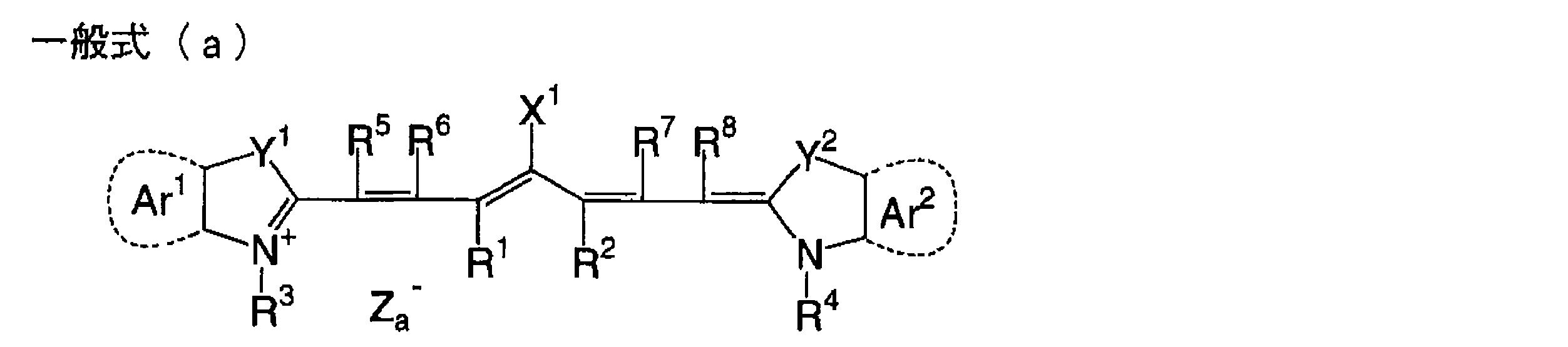
一般式(a)中、X1は、水素原子、ハロゲン原子、-NPh2、X2-L1または以下に示す基を表す。ここで、X2は酸素原子、窒素原子、または硫黄原子を示し、L1は、炭素原子数1~12の炭化水素基、ヘテロ原子(N、S、O、ハロゲン原子、Se)を有する芳香族環、ヘテロ原子を含む炭素原子数1~12の炭化水素基を示す。Xa-は後述するZa-と同様に定義され、Raは、水素原子、アルキル基、アリール基、置換または無置換のアミノ基、ハロゲン原子より選択される置換基を表す。

R1およびR2は、それぞれ独立に、炭素原子数1~12の炭化水素基を示す。感光層塗布液の保存安定性から、R1およびR2は、炭素原子数2個以上の炭化水素基であることが好ましく、更に、R1とR2とは互いに結合し、5員環または6員環を形成していることが特に好ましい。
Ar1、Ar2は、それぞれ同じでも異なっていてもよく、置換基を有していてもよい芳香族炭化水素基を示す。好ましい芳香族炭化水素基としては、ベンゼン環およびナフタレン環が挙げられる。また、好ましい置換基としては、炭素原子数12個以下の炭化水素基、ハロゲン原子、炭素原子数12個以下のアルコキシ基が挙げられる。Y1、Y2は、それぞれ同じでも異なっていてもよく、硫黄原子または炭素原子数12個以下のジアルキルメチレン基を示す。R3、R4は、それぞれ同じでも異なっていてもよく、置換基を有していてもよい炭素原子数20個以下の炭化水素基を示す。好ましい置換基としては、炭素原子数12個以下のアルコキシ基、カルボキシル基、スルホ基が挙げられる。R5、R6、R7およびR8は、それぞれ同じでも異なっていてもよく、水素原子または炭素原子数12個以下の炭化水素基を示す。原料の入手性から、好ましくは水素原子である。また、Za-は、対アニオンを示す。ただし、一般式(a)で示されるシアニン色素が、その構造内にアニオン性の置換基を有し、電荷の中和が必要ない場合にはZa-は必要ない。好ましいZa-は、感光層塗布液の保存安定性から、ハロゲンイオン、過塩素酸イオン、テトラフルオロボレートイオン、ヘキサフルオロフォスフェートイオン、およびスルホン酸イオンであり、特に好ましくは、過塩素酸イオン、ヘキサフルオロフォスフェートイオン、およびアリールスルホン酸イオンである。尚、対イオンとして、ハロゲンイオンを含有してないものが特に好ましい。
好適に用いることのできる一般式(a)で示されるシアニン色素の具体例としては、特開2001-133969号公報の段落番号[0017]~[0019]に記載されたものを挙げることができる。
また、特に好ましい他の例としてさらに、前記した特開2002-278057号公報に記載の特定インドレニンシアニン色素が挙げられる。
顔料としては、市販の顔料およびカラーインデックス(C.I.)便覧、「最新顔料便覧」(日本顔料技術協会編、1977年刊)、「最新顔料応用技術」(CMC出版、1986年刊)、「印刷インキ技術」CMC出版、1984年刊)に記載されている顔料が利用できる。
これら増感色素の好ましい添加量は、感光層の全固形分100重量部に対し、好ましくは0.05~30重量部、更に好ましくは0.1~20重量部、最も好ましくは0.2~10重量部の範囲である。
<着色剤>
本発明における感光層は、着色剤も含有していてもよい。着色剤は、染料または顔料であってもよい。着色剤については、特表2009-516222号公報および国際公開第2007/057348号パンフレットに記載の着色剤を使用することができるが、これに限定されるものではない。
本発明における感光層は、着色剤も含有していてもよい。着色剤は、染料または顔料であってもよい。着色剤については、特表2009-516222号公報および国際公開第2007/057348号パンフレットに記載の着色剤を使用することができるが、これに限定されるものではない。
着色剤として使用する顔料としては、例えば有機顔料、無機顔料、カーボングラック、金属粉末顔料、蛍光顔料などが挙げられ、有機顔料が好ましい。
有機顔料の具体例は、キナクリドン顔料、キナクリドンキノン顔料、ジオキサジン顔料、フタロシアニン顔料、アントラピリミジン顔料、アンタンスロン顔料、インダンスロン顔料、フラバンスロン顔料、ペリーレン顔料、ジケトピロロピロール顔料、ペリノン顔料、キノフタロン顔料、アントラキノン顔料、チオインジゴ顔料、ベンズイミダゾロン顔料、イソインドリノン顔料、アゾメチン顔料、およびアゾ顔料などが挙げられる。
着色剤として使用可能な顔料の具体例は、特表2009-516222号公報や特開2010-139551号公報に記載されたものが例示される。
本発明においては、シアン顔料を包含する青色着色された顔料を使用することが好ましい。
顔料は、顔料粒子の表面処理を行ってもよい。表面処理方法は、顔料の表面に樹脂をコーティングする方法、界面活性剤を塗布する方法、および反応性物質(例えば、シランカップリング剤、エポキシ化合物、ポリイソシアネートなど)を結合させる方法などが挙げられる。表面処理をした顔料の具体例としては、国際公開第02/04210号パンフレットに記載された改質顔料であり、具体的には国際公開第02/04210号パンフレットに記載された青色着色された改質顔料を使用することが好ましい。
顔料の粒径は、好ましくは10μmより小さく、より好ましくは5μmより小さく、特に好ましくは3μmより小さい。顔料の分散方法はインキまたはトナーなどの製造に用いられる公知の分散方法を用いることができる。分散方法に使用する分散機械は、超音波分散器、サンドミル、アトライター、パールミル、スーパーミル、ボールミル、羽根車、分散器、KDミル、コロイドミル、ダイナトロン、スリー-ロールミルおよび加圧混練器などが挙げられる。詳細は“Latest Pigment Applied Technology”(CMC Publications,published in 1986)に記載されている。
顔料としては、いわゆる自己分散性顔料を使用してもよく、自己分散性顔料の作製において、分散剤は必要に応じて用いなくてもよい。自己分散性顔料の具体例は、顔料表面を分散液と相溶可能とする方法で表面処理を行った顔料などが挙げられる。水性媒体中の自己分散性顔料としては、例えば、粒子表面に結合されたイオン性もしくはイオン化可能な基またはポリエチレンオキシド連鎖を有する顔料などが挙げられる。イオン性もしくはイオン化可能な基の具体例としては、酸基またはそれらの塩類、例えばカルボン酸基、スルホン酸、燐酸またはホスホン酸およびこれらの酸類のアルカリ金属塩類などが挙げられる。自己分散性顔料の具体例は、国際公開第02/04210号パンフレットに記載されており、国際公開第02/04210号パンフレット中の青色着色された自己-分散性顔料を使用することが好ましい。
顔料の使用量は、0.005g/m2~2g/m2であることが好ましく、0.007g/m2~0.5g/m2であることがより好ましく、0.01g/m2~0.2g/m2であることがさらに好ましく、0.01g/m2~0.1g/m2であることが特に好ましい。
着色剤は染料であってもよい。染料としては、既知の染料、例えば市販の染料または “Dye Handbook”(edited by the Organic Synthetic Chemistry Association,published in 1970)に記載された染料が挙げられる。染料の具体例は、例えば、アゾ染料、金属錯体塩アゾ染料、ピラゾロンアゾ染料、アントラキノン染料、フタロシアニン染料、カルビオニウム染料、キノンイミン染料、メチン染料などを包含する。フタロシアニン染料が挙げられる。これら染料は、有機染料を形成する塩であり、油溶性染料および塩基性染料であってもよい。
染料の具体例としては、特表2009-516602号公報、英国特許第219279号公報に記載のものが挙げられる。
染料の使用量は、0.005g/m2~2g/m2が好ましく、0.007g/m2~0.5g/m2がより好ましく、0.01g/m2~0.2g/m2がさらに好ましく、0.01g/m2~0.1g/m2が特に好ましい。
<焼出し剤>
本発明では、感光層に焼出し剤を含有させてもよい。焼出し剤は欧州特許出願公開第1491356号明細書19および20頁[0116]~[0119]、米国特許第2005/8971号明細書17頁[0168]~[0172]、特表2009-516222号公報および国際公開第2007/057348号パンフレットに記載されているような化合物が挙げられるが、これに限定されるものではない。好ましい焼出し剤としては、2005年7月1日に出願された公開されていないPCT出願であるPCT/欧州特許第2005/053141号明細書9頁1行~20頁27行に記載されている化合物である。2005年6月21日に出願された公開されていない欧州特許第05105440.1号明細書5頁32行~32頁9行に記載されているようなIR-染料がより好ましい。
本発明では、感光層に焼出し剤を含有させてもよい。焼出し剤は欧州特許出願公開第1491356号明細書19および20頁[0116]~[0119]、米国特許第2005/8971号明細書17頁[0168]~[0172]、特表2009-516222号公報および国際公開第2007/057348号パンフレットに記載されているような化合物が挙げられるが、これに限定されるものではない。好ましい焼出し剤としては、2005年7月1日に出願された公開されていないPCT出願であるPCT/欧州特許第2005/053141号明細書9頁1行~20頁27行に記載されている化合物である。2005年6月21日に出願された公開されていない欧州特許第05105440.1号明細書5頁32行~32頁9行に記載されているようなIR-染料がより好ましい。
<コントラスト>
画像のコントラストは、露光部と非露光部との間の光学濃度の差によって定義され、コントラストはより高い方が好ましい。
画像のコントラストは、露光部と非露光部との間の光学濃度の差によって定義され、コントラストはより高い方が好ましい。
コントラストは、露光部の光学濃度の増加、および/または非露光部の光学濃度の減少によって増加する。露光部の光学濃度は、露光部で残存する着色剤の減衰係数の量、および焼出し剤によって形成された色の強度により増加する。非露光部では、着色剤の量は可能な限り少ないことが好ましく、焼出し剤の量も可能な限り少ないことが好ましい。光学濃度は、何種類かのフィルター(例えば、シアン、マゼンタ、イエロー)を有する光学濃度計により反射率で測定できる。露光部および非露光部における光学濃度における差は、好ましくは少なくとも0.3、より好ましくは少なくとも0.4、最も好ましくは少なくとも0.5である。コントラスト値に関する具体的な上限はないが、一般的に、コントラストは3.0未満であり、2.0未満である。良好なコントラストを得るためには、着色剤の色の選択が重要であり、好ましい色はシアンまたは青色である。
コントラストについての詳細は、特表2009-516222号公報および国際公開第2007/057348号パンフレットに記載されており、参照することができる。
コントラストについての詳細は、特表2009-516222号公報および国際公開第2007/057348号パンフレットに記載されており、参照することができる。
<界面活性剤>
本発明では、現像性の促進および塗布面状を向上させるため、界面活性剤を含有させてもよい。前記界面活性剤としては、重合体状および小分子状の両方の界面活性剤を使用でき、非イオン系界面活性剤が好ましい。非イオン系界面活性剤は、1つもしくはそれ以上のポリエーテル(例えばポリエチレングリコール、ポリプロピレングリコール、並びにエチレングリコールおよびプロピレングリコールの共重合体)セグメントを含有する重合体およびオリゴマー類;プロピレングリコールおよびエチレングリコールのブロック共重合体(プロピレンオキシドおよびエチレンオキシドのブロック共重合体とも称する);エトキシル化されたまたはプロポキシル化されたアクリレートオリゴマー類;並びにポリエトキシル化されたアルキルフェノール類およびポリエトキシル化された脂肪アルコール類などが挙げられる。
また、界面活性剤については、特表2009-516222号公報および国際公開第2007/057348号パンフレットに記載の界面活性剤を使用することができるが、これに限定されるものではない。
非イオン系界面活性剤の前記感光層中の含有量は、好ましくは0.1~30重量%であり、より好ましくは0.5~20%であり、さらに好ましくは1~15%である。
界面活性剤については、後述の現像液に添加してもよい界面活性剤を使用することもできる。
<低分子親水性化合物>
前記感光層は、耐刷性を低下させることなく機上現像性を向上させるために、低分子親水性化合物を含有してもよい。
前記低分子親水性化合物としては、例えば、水溶性有機化合物としては、エチレングリコール、ジエチレングリコール、トリエチレングリコール、プロピレングリコール、ジプロピレングリコール、トリプロピレングリコール等のグリコール類及びそのエーテルまたはエステル誘導体類、グリセリン、ペンタエリスリトール、トリス(2-ヒドロキシエチル)イソシアヌレート等のポリオール類、トリエタノールアミン、ジエタノールアミン、モノエタノールアミン等の有機アミン類及びその塩、アルキルスルホン酸、トルエンスルホン酸、ベンゼンスルホン酸等の有機スルホン酸類及びその塩、アルキルスルファミン酸等の有機スルファミン酸類及びその塩、アルキル硫酸、アルキルエーテル硫酸等の有機硫酸類及びその塩、フェニルホスホン酸等の有機ホスホン酸類及びその塩、酒石酸、シュウ酸、クエン酸、リンゴ酸、乳酸、グルコン酸、アミノ酸類等の有機カルボン酸類及びその塩、ベタイン類等が挙げられる。
本発明においてはこれらの中でも、ポリオール類、有機硫酸塩類、有機スルホン酸塩類、ベタイン類から選ばれる少なくとも一つを含有させることが好ましい。
これらの具体例としては、特開2012-031400号公報の段落番号0137~0139の記載を参酌できる。
これらの具体例としては、特開2012-031400号公報の段落番号0137~0139の記載を参酌できる。
前記低分子親水性化合物の、前記感光層中の含有量は、前記感光層全固形分に対して0.5~20重量%が好ましく、1~15重量%がより好ましく、2~10重量%がさらに好ましい。この範囲で良好な機上現像性と耐刷性が得られる。低分子親水性化合物は単独で用いてもよく、2種以上を混合して用いてもよい。
<感脂化剤>
前記感光層には、着肉性を向上させるために、ホスホニウム化合物、含窒素低分子化合物、アンモニウム基含有ポリマーなどの感脂化剤を含有させることができる。特に、保護層が無機質の層状化合物を含有する場合、感脂化剤は、無機質の層状化合物の表面被覆剤として機能し、無機質の層状化合物による印刷途中の着肉性低下を防止する。
前記感光層には、着肉性を向上させるために、ホスホニウム化合物、含窒素低分子化合物、アンモニウム基含有ポリマーなどの感脂化剤を含有させることができる。特に、保護層が無機質の層状化合物を含有する場合、感脂化剤は、無機質の層状化合物の表面被覆剤として機能し、無機質の層状化合物による印刷途中の着肉性低下を防止する。
好適なホスホニウム化合物としては、特開2006-297907号公報及び特開2007-50660号公報に記載のホスホニウム化合物を挙げることができる。具体例としては、テトラブチルホスホニウムヨージド、ブチルトリフェニルホスホニウムブロミド、テトラフェニルホスホニウムブロミド、1,4-ビス(トリフェニルホスホニオ)ブタン=ジ(ヘキサフルオロホスファート)、1,7-ビス(トリフェニルホスホニオ)ヘプタン=スルファート、1,9-ビス(トリフェニルホスホニオ)ノナン=ナフタレン-2,7-ジスルホナートなどが挙げられる。
前記含窒素低分子化合物としては、アミン塩類、第4級アンモニウム塩類が挙げられる。またイミダゾリニウム塩類、ベンゾイミダゾリニウム塩類、ピリジニウム塩類、キノリニウム塩類も挙げられる。なかでも、第4級アンモニウム塩類及びピリジニウム塩類が好ましい。具体例としては、テトラメチルアンモニウム=ヘキサフルオロホスファート、テトラブチルアンモニウム=ヘキサフルオロホスファート、ドデシルトリメチルアンモニウム=p-トルエンスルホナート、ベンジルトリエチルアンモニウム=ヘキサフルオロホスファート、ベンジルジメチルオクチルアンモニウム=ヘキサフルオロホスファート、ベンジルジメチルドデシルアンモニウム=ヘキサフルオロホスファート、特開2008-284858号公報の段落番号〔0021〕~〔0037〕、特開2009-90645号公報の段落番号〔0030〕~〔0057〕に記載の化合物などが挙げられる。
前記アンモニウム基含有ポリマーとしては、その構造中にアンモニウム基を有すれば如何なるものでもよいが、側鎖にアンモニウム基を有する(メタ)アクリレートを共重合成分として5~80mol%含有するポリマーが好ましい。具体例としては、特開2009-208458号公報の段落番号〔0089〕~〔0105〕に記載のポリマーが挙げられる。
前記アンモニウム塩含有ポリマーは、下記の測定方法で求められる還元比粘度(単位:ml/g)の値が、5~120の範囲のものが好ましく、10~110の範囲のものがより好ましく、15~100の範囲のものが特に好ましい。上記還元比粘度を重量平均分子量に換算すると、10000~150000が好ましく、17000~140000がより好ましく、20000~130000が特に好ましい。
<<還元比粘度の測定方法>>
30%ポリマー溶液3.33g(固形分として1g)を、20mlのメスフラスコに秤量し、N-メチルピロリドンでメスアップする。この溶液を30℃の恒温槽で30分間静置し、ウベローデ還元粘度管(粘度計定数=0.010cSt/s)に入れて30℃にて流れ落ちる時間を測定する。なお測定は同一サンプルで2回測定し、その平均値を算出する。同様にブランク(N-メチルピロリドンのみ)の場合も測定し、下記式から還元比粘度(ml/g)を算出する。
30%ポリマー溶液3.33g(固形分として1g)を、20mlのメスフラスコに秤量し、N-メチルピロリドンでメスアップする。この溶液を30℃の恒温槽で30分間静置し、ウベローデ還元粘度管(粘度計定数=0.010cSt/s)に入れて30℃にて流れ落ちる時間を測定する。なお測定は同一サンプルで2回測定し、その平均値を算出する。同様にブランク(N-メチルピロリドンのみ)の場合も測定し、下記式から還元比粘度(ml/g)を算出する。

以下に、アンモニウム基含有ポリマーの具体例としては、特開2011-251431号公報の段落番号0177に記載のものを採用できる。
前記感脂化剤の含有量は、感光層の全固形分に対して0.01~30.0重量%が好ましく、0.1~15.0重量%がより好ましく、1~5重量%がさらに好ましい。
<疎水化前駆体>
前記感光層には、機上現像性を向上させるため、疎水化前駆体を含有させることができる。疎水化前駆体とは、熱が加えられたときに前記感光層を疎水性に変換できる微粒子を意味する。微粒子としては、疎水性熱可塑性ポリマー微粒子、熱反応性ポリマー微粒子、重合性基を有するポリマー微粒子、疎水性化合物を内包しているマイクロカプセル及びミクロゲル(架橋ポリマー微粒子)から選ばれる少なくとも1つであることが好ましい。なかでも、重合性基を有するポリマー微粒子及びミクロゲルが好ましい。
前記感光層には、機上現像性を向上させるため、疎水化前駆体を含有させることができる。疎水化前駆体とは、熱が加えられたときに前記感光層を疎水性に変換できる微粒子を意味する。微粒子としては、疎水性熱可塑性ポリマー微粒子、熱反応性ポリマー微粒子、重合性基を有するポリマー微粒子、疎水性化合物を内包しているマイクロカプセル及びミクロゲル(架橋ポリマー微粒子)から選ばれる少なくとも1つであることが好ましい。なかでも、重合性基を有するポリマー微粒子及びミクロゲルが好ましい。
前記疎水性熱可塑性ポリマー微粒子としては、1992年1月のResearch Disclosure、No.333003、特開平9-123387号公報、特開平9-131850号公報、特開平9-171249号公報、特開平9-171250号公報及び欧州特許第931647号明細書などに記載の疎水性熱可塑性ポリマー微粒子を好適なものとして挙げることができる。
このようなポリマー微粒子を構成するポリマーの具体例としては、エチレン、スチレン、塩化ビニル、アクリル酸メチル、アクリル酸エチル、メタクリル酸メチル、メタクリル酸エチル、塩化ビニリデン、アクリロニトリル、ビニルカルバゾール、ポリアルキレン構造を有するアクリレートまたはメタクリレートなどのモノマーのホモポリマーもしくはコポリマーまたはそれらの混合物を挙げることができる。その中で、より好適なものとして、ポリスチレン、スチレンおよびアクリロニトリルを含む共重合体、ポリメタクリル酸メチルを挙げることができる。
このようなポリマー微粒子を構成するポリマーの具体例としては、エチレン、スチレン、塩化ビニル、アクリル酸メチル、アクリル酸エチル、メタクリル酸メチル、メタクリル酸エチル、塩化ビニリデン、アクリロニトリル、ビニルカルバゾール、ポリアルキレン構造を有するアクリレートまたはメタクリレートなどのモノマーのホモポリマーもしくはコポリマーまたはそれらの混合物を挙げることができる。その中で、より好適なものとして、ポリスチレン、スチレンおよびアクリロニトリルを含む共重合体、ポリメタクリル酸メチルを挙げることができる。
本発明に用いられる疎水性熱可塑性ポリマー微粒子の平均粒径は0.01~2.0μmが好ましい。
本発明に用いられる熱反応性ポリマー微粒子としては、熱反応性基を有するポリマー微粒子が挙げられ、これらは、熱反応による架橋及びその際の官能基変化により疎水化領域を形成する。
本発明に用いる熱反応性基を有するポリマー微粒子における熱反応性基としては、化学結合が形成されるならば、どのような反応を行う官能基でもよいが、重合性基であることが好ましく、その例として、ラジカル重合反応を行うエチレン性不飽和基(例えば、アクリロイル基、メタクリロイル基、ビニル基、アリル基など)、カチオン重合性基(例えば、ビニル基、ビニルオキシ基、エポキシ基、オキセタニル基など)、付加反応を行うイソシアナト基またはそのブロック体、エポキシ基、ビニルオキシ基及びこれらの反応相手である活性水素原子を有する官能基(例えば、アミノ基、ヒドロキシ基、カルボキシ基など)、縮合反応を行うカルボキシ基及び反応相手であるヒドロキシ基またはアミノ基、開環付加反応を行う酸無水物及び反応相手であるアミノ基またはヒドロキシ基などを好適なものとして挙げることができる。
本発明に用いる熱反応性基を有するポリマー微粒子における熱反応性基としては、化学結合が形成されるならば、どのような反応を行う官能基でもよいが、重合性基であることが好ましく、その例として、ラジカル重合反応を行うエチレン性不飽和基(例えば、アクリロイル基、メタクリロイル基、ビニル基、アリル基など)、カチオン重合性基(例えば、ビニル基、ビニルオキシ基、エポキシ基、オキセタニル基など)、付加反応を行うイソシアナト基またはそのブロック体、エポキシ基、ビニルオキシ基及びこれらの反応相手である活性水素原子を有する官能基(例えば、アミノ基、ヒドロキシ基、カルボキシ基など)、縮合反応を行うカルボキシ基及び反応相手であるヒドロキシ基またはアミノ基、開環付加反応を行う酸無水物及び反応相手であるアミノ基またはヒドロキシ基などを好適なものとして挙げることができる。
本発明に用いられるマイクロカプセルとしては、例えば、特開2001-277740号公報、特開2001-277742号公報に記載のごとく、感光層の構成成分の全てまたは一部をマイクロカプセルに内包させたものである。なお、感光層の構成成分は、マイクロカプセル外にも含有させることもできる。さらに、マイクロカプセルを含有する感光層は、疎水性の構成成分をマイクロカプセルに内包し、親水性の構成成分をマイクロカプセル外に含有することが好ましい態様である。
本発明に用いられるミクロゲルは、その中または表面の少なくとも一方に、感光層の構成成分の一部を含有することができる。特に、ラジカル重合性基をその表面に有することによって反応性ミクロゲルとした態様が、画像形成感度や耐刷性の観点から特に好ましい。
前記感光層の構成成分をマイクロカプセル化もしくはミクロゲル化するには、公知の方法が適用できる。
マイクロカプセルあるいはミクロゲルの平均粒径は、0.01~3.0μmが好ましく、0.05~2.0μmがさらに好ましく、0.10~1.0μmが特に好ましい。この範囲内で良好な解像度と経時安定性が得られる。
前記疎水化前駆体の含有量は、前記感光層全固形分の5~90重量%が好ましい。
<その他の感光層成分>
感光層は、さらに連鎖移動剤を含有することが好ましい。連鎖移動剤としては、例えば、分子内にSH、PH、SiH、GeHを有する化合物群が用いられる。これらは、低活性のラジカル種に水素供与して、ラジカルを生成するか、もしくは、酸化された後、脱プロトンすることによりラジカルを生成しうる。
本発明の感光層には、特に、チオール化合物(例えば、2-メルカプトベンズイミダゾール類、2-メルカプトベンズチアゾール類、2-メルカプトベンズオキサゾール類、3-メルカプトトリアゾール類、5-メルカプトテトラゾール類等)を連鎖移動剤として好ましく用いることができる。
本発明の感光層には、さらに、必要に応じて種々の添加剤を含有させることができる。添加剤としては、現像性と耐刷性両立の為のマイクロカプセル、現像性の向上やマイクロカプセルの分散安定性向上などのための親水性ポリマー、画像部と非画像部を視認するための着色剤や焼き出し剤、感光層の製造中または保存中のラジカル重合性化合物の不要な熱重合を防止するための重合禁止剤、酸素による重合阻害を防止するための高級脂肪誘導体、画像部の硬化皮膜強度向上のための無機微粒子、現像性向上のための親水性低分子化合物、感度向上の為の共増感剤や連鎖移動剤、可塑性向上のための可塑剤等を添加することができる。これの化合物はいずれも公知のものを使用でき、例えば、特開2007-206217号公報〔0161〕~〔0215〕に記載の化合物を使用することができる。
<感光層の形成>
本発明の感光層は、必要な上記各成分を溶剤に分散または溶解して塗布液を調製し、塗布して形成される。ここで使用する溶剤としては、メチルエチルケトン、エチレングリコールモノメチルエーテル、1-メトキシ-2-プロパノール、2-メトキシエチルアセテート、1-メトキシ-2-プロピルアセテート、γ-ブチルラクトン等を挙げることができるが、これに限定されるものではない。これらの溶剤は、単独または混合して使用される。塗布液の固形分濃度は、好ましくは1~50重量%である。
本発明の感光層は、必要な上記各成分を溶剤に分散または溶解して塗布液を調製し、塗布して形成される。ここで使用する溶剤としては、メチルエチルケトン、エチレングリコールモノメチルエーテル、1-メトキシ-2-プロパノール、2-メトキシエチルアセテート、1-メトキシ-2-プロピルアセテート、γ-ブチルラクトン等を挙げることができるが、これに限定されるものではない。これらの溶剤は、単独または混合して使用される。塗布液の固形分濃度は、好ましくは1~50重量%である。
また塗布、乾燥後に得られる支持体上の感光層塗布量(固形分)は、0.3~3.0g/m2が好ましい。塗布する方法としては、種々の方法を用いることができる。例えば、バーコーター塗布、回転塗布、スプレー塗布、カーテン塗布、ディップ塗布、エアーナイフ塗布、ブレード塗布、ロール塗布等を挙げられる。
<保護層>
本発明の平版印刷版原版には、露光時の重合反応を妨害する酸素の拡散侵入を遮断するため、感光層上に保護層(酸素遮断層)が設けられることが好ましい。保護層に使用できる材料としては例えば、比較的結晶性に優れた水溶性高分子化合物を用いることが好ましく、具体的には、ポリビニルアルコールを主成分として用いる事が、酸素遮断性、現像除去性といった基本特性的にもっとも良好な結果を与える。
本発明の平版印刷版原版には、露光時の重合反応を妨害する酸素の拡散侵入を遮断するため、感光層上に保護層(酸素遮断層)が設けられることが好ましい。保護層に使用できる材料としては例えば、比較的結晶性に優れた水溶性高分子化合物を用いることが好ましく、具体的には、ポリビニルアルコールを主成分として用いる事が、酸素遮断性、現像除去性といった基本特性的にもっとも良好な結果を与える。
保護層に使用するポリビニルアルコールは、必要な酸素遮断性と水溶性を有するための、未置換ビニルアルコール単位を含有する限り、一部がエステル、エーテル、およびアセタールで置換されていても良い。また、同様に一部が他の共重合成分を有していても良い。ポリビニルアルコールはポリ酢酸ビニルを加水分解することにより得られるが、ポリビニルアルコールの具体例としては71~100mol%加水分解され、重合繰り返し単位が300から2400の範囲のものをあげる事ができる。具体的には、株式会社クラレ製のPVA-105、PVA-110、PVA-117、PVA-117H、PVA-120、PVA-124、PVA-124H、PVPVA-CS、PVA-CST、PVA-HC、PVA-203、PVA-204、PVA-205、PVA-210、PVA-217、PVA-220、PVA-224、PVA-217EE、PVA-217E、PVA-220E、PVA-224E、PVA-405、PVA-420、PVA-613、L-8等が挙げられ、これらは単独または混合して使用できる。好ましい態様としてはポリビニルアルコールの保護層中の含有率が20~95重量%、より好ましくは、30~90重量%である。
また、公知の変性ポリビニルアルコールも好ましく用いることができる。特に、カルボン酸基又はスルホン酸基を有する酸変性ポリビニルアルコールが好ましく用いられる。ポリビニルアルコールと混合して使用する成分としてはポリビニルピロリドンまたはその変性物が酸素遮断性、現像除去性といった観点から好ましく、保護層中の含有率が3.5~80重量%、好ましくは10~60重量%、さらに好ましくは15~30重量%である。
保護層の他の組成物として、グリセリン、ジプロピレングリコール等を(共)重合体に対して数重量%相当量添加して可撓性を付与することができ、また、アルキル硫酸ナトリウム、アルキルスルホン酸ナトリウム等のアニオン界面活性剤;アルキルアミノカルボン酸塩、アルキルアミノジカルボン酸塩等の両性界面活性剤;ポリオキシエチレンアルキルフェニルエーテル等の非イオン界面活性剤を(共)重合体に対して数重量%添加することができる。
さらに、本発明の平版印刷版原版における保護層には、酸素遮断性や感光層表面保護性を向上させる目的で、特開2006-106700号公報〔0018〕~〔0024〕に記載の無機質の層状化合物を含有させることも好ましい。無機質の層状化合物の中でも、合成の無機質の層状化合物であるフッ素系の膨潤性合成雲母が特に有用である。
保護層の塗布量としては、乾燥後の塗布量で、0.05~10g/m2の範囲であることが好ましく、無機質の層状化合物を含有する場合には、0.1~0.5g/m2の範囲であることがさらに好ましく、無機質の層状化合物を含有しない場合には、0.5~5g/m2の範囲であることがさらに好ましい。
その他、本発明の平版印刷版原版からの平版印刷版の製版プロセスとしては、必要に応じ、露光前、露光中、露光から現像までの間に、全面を加熱してもよい。この様な加熱により、該感光層中の画像形成反応が促進され、感度や耐刷性の向上や感度の安定化といった利点が生じ得る。さらに、画像強度・耐刷性の向上を目的として、現像後の画像に対し、全面後加熱もしくは全面露光を行う事も有効である。通常現像前の加熱は150℃以下の穏和な条件で行う事が好ましい。温度が高すぎると、未露光部が硬化してしまう等の問題を生じる。現像後の加熱には非常に強い条件を利用する。通常は100~500℃の範囲である。温度が低いと十分な画像強化作用が得られず、高すぎる場合には支持体の劣化、画像部の熱分解といった問題を生じる。
上記の現像処理に先立って、平版印刷版原版は、線画像、網点画像等を有する透明原画を通してレーザー露光するかデジタルデータによるレーザー光走査等で画像様に露光される。
望ましい光源の波長は300nmから450nm又は750nmから1400nmの波長が好ましく用いられる。300nmから450nmの場合は、この領域に吸収極大を有する増感色素を感光層に有する平版印刷版原版が用いられ、750nmから1400nmの場合は、この領域に吸収を有する増感色素である赤外線吸収剤を含有する平版印刷版原版が用いられる。300nmから450nmの光源としては、半導体レーザーが好適である。750nmから1400nmの光源としては、赤外線を放射する固体レーザー及び半導体レーザーが好適である。露光機構は、内面ドラム方式、外面ドラム方式、フラットベッド方式等の何れでもよい。
望ましい光源の波長は300nmから450nm又は750nmから1400nmの波長が好ましく用いられる。300nmから450nmの場合は、この領域に吸収極大を有する増感色素を感光層に有する平版印刷版原版が用いられ、750nmから1400nmの場合は、この領域に吸収を有する増感色素である赤外線吸収剤を含有する平版印刷版原版が用いられる。300nmから450nmの光源としては、半導体レーザーが好適である。750nmから1400nmの光源としては、赤外線を放射する固体レーザー及び半導体レーザーが好適である。露光機構は、内面ドラム方式、外面ドラム方式、フラットベッド方式等の何れでもよい。
[平版印刷版の製造方法]
本発明の平版印刷版原版を画像露光して現像処理を行うことで平版印刷版を製造することができる。
本発明の平版印刷版の製造方法は、本発明の平版印刷版原版を、画像様に露光する露光工程と;露光した前記平版印刷版原版を、pHが2~14の現像液で現像する現像工程を含み;前記現像工程において、前記現像液の存在下、前記感光層の非露光部と前記保護層とを同時に除去する工程を含むことを特徴とする。
本発明の平版印刷版の製造方法は、前記感光層の前記支持体とは反対側の表面上に、保護層を形成する工程を含み;前記現像工程において、さらに界面活性剤を含有する前記現像液の存在下、非露光部の感光層と前記保護層とを同時に除去する工程を含む(但し、水洗工程を含まない)、ことが好ましい
本発明の平版印刷版の製造方法の第二の態様は、本発明の平版印刷版原版を、画像様に露光する工程と、印刷機上で印刷インキと湿し水を供給して非露光部の前記感光層を除去する工程とを含むことを特徴とする。
以下、本発明の平版印刷版の製造方法について、各工程の好ましい態様を順に説明する。なお、本発明の平版印刷版の製造方法によれば、本発明の平版印刷版原版は前記現像工程において水洗工程を含む場合も平板印刷版を製造することができる。
現像液は、印刷版の平版像を酸化、指紋、脂肪、油分、塵などによる汚染から防止するため、および引っ掻きなどの損傷を防止するために用いてもよい。現像液の表面張力は好ましくは20~50mN/mであり、非イオン系(ノニオン)界面活性剤であることが好ましい。この場合、現像処理後に版上に残存する層は好ましくは0.005~20g/m2であり、より好ましくは0.010~10g/m2であり、さらに好ましくは0.020~5g/m2の表面保護化合物を含んでなることが好ましい。現像液(ガム液)については、特表2009-516222号公報および国際公開第2007/057348号パンフレットに記載の現像液を使用することができるが、これに限定されるものではない。
<現像液中の表面保護成分>
また、本発明の現像液に用いられる表面保護を行う水溶性高分子化合物としては、大豆多糖類、変性澱粉、アラビアガム、デキストリン、繊維素誘導体(例えばカルボキシメチルセルロース、カルボキシエチルセルロース、メチルセルロース等)およびその変性体、プルラン、ポリビニルアルコールおよびその誘導体、ポリビニルピロリドン、ポリアクリルアミドおよびアクリルアミド共重合体、ビニルメチルエーテル/無水マレイン酸共重合体、酢酸ビニル/無水マレイン酸共重合体、スチレン/無水マレイン酸共重合体などが挙げられる。
また、本発明の現像液に用いられる表面保護を行う水溶性高分子化合物としては、大豆多糖類、変性澱粉、アラビアガム、デキストリン、繊維素誘導体(例えばカルボキシメチルセルロース、カルボキシエチルセルロース、メチルセルロース等)およびその変性体、プルラン、ポリビニルアルコールおよびその誘導体、ポリビニルピロリドン、ポリアクリルアミドおよびアクリルアミド共重合体、ビニルメチルエーテル/無水マレイン酸共重合体、酢酸ビニル/無水マレイン酸共重合体、スチレン/無水マレイン酸共重合体などが挙げられる。
上記大豆多糖類は、公知のものが使用でき、例えば市販品として商品名ソヤファイブ(不二製油(株)製)があり、各種グレードのものを使用することができる。好ましく使用できるものは、10重量%水溶液の粘度が10~100mPa/secの範囲にあるものである。
上記変性澱粉も、公知のものが使用でき、トウモロコシ、じゃがいも、タピオカ、米、小麦等の澱粉を酸または酵素等で1分子当たりグルコース残基数5~30の範囲で分解し、更にアルカリ中でオキシプロピレンを付加する方法等で作ることができる。
また、水溶性高分子化合物には、カルボン酸、スルホン酸もしくはホスホン酸基を含有する単量体またはそれらの塩類、例えば(メタ)アクリル酸、酢酸ビニル、スチレンスルホン酸、ビニルスルホン酸、ビニルホスホン酸またはアクリルアミドプロパンスルホン酸のホモポリマーおよび/または共重合体を含有させてもよい。
水溶性高分子化合物は2種以上を併用することもできる。水溶性高分子化合物の現像液中における含有量は、0.1~20重量%が好ましく、より好ましくは0.5~10重量%である。
表面保護剤としての使用のための界面活性剤の例はアニオン系、カチオン系、両性イオン系または非イオン系界面活性剤を包含する。コーティングされた層の表面性質を改良するために、ゴム溶液は表面保護剤としての1種もしくはそれ以上の上記の親水性重合体並びに、その上に、1種もしくはそれ以上の界面活性剤も含んでなりうる。ゴム溶液の表面張力は好ましくは20~50mN/mである。好ましくは非イオン系(ノニオン)界面活性剤である。
アニオン系界面活性剤の例は、アリフェート類(aliphates)、アビエテート類(abietates)、ヒドロキシアルカンスルホネート類、アルカンスルホネート類、ジアルキルスルホスクシネート類、直鎖状アルキルベンゼンスルホネート類、分枝鎖状アルキルベンゼンスルホネート類、アルキルナフタレンスルホネート類、アルキルフェノキシポリオキシエチレンプロピルスルホネート類、ポリオキシエチレンアルキルスルホフェニルエーテル類の塩類、N-メチル-N-オレイルアミノエタンスルホン酸ナトリウム、N-アルキルスルホ琥珀酸モノアミド二ナトリウム、石油スルホネート類、硫酸化されたひまし油、硫酸化された牛脂油、脂肪族アルキルエステル類の硫酸エステル類の塩類、アルキル硫酸エステル類の塩類、ポリオキシエチレンアルキルエーテル類の硫酸エステル類、脂肪族モノグリセリド類の硫酸エステル類の塩類、ポリオキシエチレンアルキルフェニルエーテル類の硫酸エステル類の塩類、ポリオキシエチレンスチリルフェニルエーテル類の硫酸エステル類の塩類、アルキル燐酸エステル類の塩類、ポリオキシエチレンアルキルエーテル類の燐酸エステル類の塩類、ポリオキシエチレンアルキルフェニルエーテル類の燐酸エステル類の塩類、スチレン無水マレイン酸共重合体の部分的に鹸化された化合物、オレフィン-無水マレイン酸共重合体の部分的に鹸化された化合物、およびナフタレンスルホネートホルマリン縮合体を包含する。これらのアニオン系界面活性剤の中で、ジアルキルスルホスクシネート類、アルキル硫酸エステル類の塩類およびアルキルナフタレンスルホネート類が特に好ましい。
適当なアニオン系界面活性剤の具体例は、ドデシルフェノキシベンゼンジスルホン酸ナトリウム、アルキル化されたナフタレンスルホネートのナトリウム塩、メチレン-ジナフタレン-ジスルホン酸二ナトリウム、ドデシル-ベンゼンスルホン酸ナトリウム、スルホン化されたアルキル-ジフェニルオキシド、ペルフルオロアルキルスルホン酸アンモニウムまたはカリウムおよびジオクチル-スルホ琥珀酸ナトリウムを包含する。
本発明の現像液に用いられるカチオン系界面活性剤としては、特に限定されないが、従来公知のものを用いることができる。例えば、アルキルアミン塩類、第四級アンモニウム塩類、ポリオキシエチレンアルキルアミン塩類、ポリエチレンポリアミン誘導体が挙げられる。
非イオン系界面活性剤の適当な例は、ポリオキシエチレンアルキルエーテル類、アリール基がフェニル基、ナフチル基もしくは芳香族複素環式基でありうるポリオキシエチレンアルキルアリールエーテル類、ポリオキシエチレンポリスチリルフェニルエーテル類、ポリオキシエチレンポリオキシプロピレンアルキルエーテル類、ポリオキシエチレンポリオキシプロピレンブロック重合体、グリセリン脂肪族酸類の部分的エステル類、ソルビタン脂肪族酸の部分的エステル類、ペンタエリトリトール脂肪族酸の部分的エステル類、プロピレングリコールモノ脂肪族エステル類、スクロース脂肪族酸類の部分的エステル類、ポリオキシエチレンソルビタン脂肪族酸の部分的エステル類、ポリオキシエチレンソルビトール脂肪族酸類の部分的エステル類、ポリエチレングリコール脂肪族エステル類、ポリ-グリセリン脂肪族酸類の部分的エステル類、ポリオキシエチレン化されたひまし油類、ポリオキシエチレングリセリン脂肪族酸類の部分的エステル類、脂肪族ジエタノールアミド類、N,N-ビス-2-ヒドロキシアルキルアミン類、ポリオキシエチレンアルキルアミン類、トリエタノールアミン脂肪族エステル類、およびトリアルキルアミンオキシド類を包含する。これらの非イオン系界面活性剤の中で、ポリオキシエチレンアルキルフェニルエーテル類、ポリオキシエチレンアルキルナフチルエーテル類およびポリオキシエチレン-ポリオキシプロピレンブロック重合体が特に好ましい。さらに、弗素性および珪素性のアニオン系および非イオン系界面活性剤も同様に使用できる。
2種もしくはそれ以上の上記界面活性剤を組み合わせて使用することができる。例えば、2種もしくはそれ以上の異なるアニオン系界面活性剤の組み合わせまたはアニオン系界面活性剤および非イオン系界面活性剤の組み合わせが好ましいこともある。そのような界面活性剤の量は具体的に限定されないが好ましくは0.01~30重量%、より好ましくは0.05~20重量%である。
本発明の現像液に用いられる両性イオン系界面活性剤としては、特に限定されないが、アルキルジメチルアミンオキシドなどのアミンオキシド系、アルキルベタインなどのベタイン系、アルキルアミノ脂肪酸ナトリウムなどのアミノ酸系が挙げられる。
特に、置換基を有してもよいアルキルジメチルアミンオキシド、置換基を有してもよいアルキルカルボキシベタイン、置換基を有してもよいアルキルスルホベタインが好ましく用いられる。これらの具体例は、特開2008-203359号公報の段落番号0255~0278、特開2008-276166号公報の段落番号0028~0052等に記載されているものを用いることができる。
特に、置換基を有してもよいアルキルジメチルアミンオキシド、置換基を有してもよいアルキルカルボキシベタイン、置換基を有してもよいアルキルスルホベタインが好ましく用いられる。これらの具体例は、特開2008-203359号公報の段落番号0255~0278、特開2008-276166号公報の段落番号0028~0052等に記載されているものを用いることができる。
本発明において現像液処理に用いられる現像液は、pHが2~14の水溶液、または界面活性剤を含む。本発明において好ましく用いられる現像液は、pHが2~11の水溶液である。水を主成分(水を60質量%以上含有)とする水溶液が好ましく、特に、界面活性剤(アニオン系、ノニオン系、カチオン系、両性イオン系等)を含有する水溶液や、水溶性高分子化合物を含有する水溶液が好ましい。界面活性剤と水溶性高分子化合物の両方を含有する水溶液も好ましい。該現像液のpHは、より好ましくは5~10.7、さらに好ましくは6~10.5、最も好ましくは6.5~10.3である。
ゴム溶液のpHは一般的には、0.01~15重量%、好ましくは0.02~10重量%、の量の鉱酸、有機酸または無機塩で調節される。鉱酸類の例は、硝酸、硫酸、燐酸およびメタ燐酸を包含する。特に有機酸類がpH調節剤としてそして減感剤として使用される。有機酸類の例は、カルボン酸類、スルホン酸類、ホスホン酸類またはそれらの塩類、例えば琥珀酸塩類、燐酸塩類、ホスホン酸塩類、硫酸塩類およびスルホン酸塩類、を包含する。有機酸の具体例は、クエン酸、酢酸、シュウ酸、マロン酸、p-トルエンスルホン酸、酒石酸、リンゴ酸、乳酸、レブリン酸、フィチン酸および有機ホスホン酸を包含する。
ゴム溶液は好ましくは無機塩をさらに含んでなる。無機塩の例は、硝酸マグネシウム、一塩基性燐酸ナトリウム、二塩基性燐酸ナトリウム、硫酸ニッケル、ヘキサメタ燐酸ナトリウムおよびトリポリ燐酸ナトリウムを包含する。燐酸一水素アルカリ-金属塩、燐酸二水素アルカリ-金属塩、燐酸アルカリ-金属塩、例えばKH2PO4またはNaH2PO4、Na2HPO4、Na3PO4、が最も好ましい。他の無機塩類、例えば硫酸マグネシウムまたは硝酸亜鉛、を腐食抑制剤として使用することができる。鉱酸、有機酸または無機塩は単独でまたはそれらの1種もしくはそれ以上と組み合わせて使用できる。
本発明の別の態様によると、版の処理における現像剤としてのゴム溶液は好ましくはアニオン系界面活性剤および無機塩の混合物を含んでなる。この混合物ではアニオン系界面活性剤は好ましくはスルホン酸基を有するアニオン系界面活性剤、より好ましくはモノ-もしくはジ-アルキル置換されたジフェニルエーテル-スルホン酸のアルカリ-金属塩、であり、そして無機塩は好ましくは一もしくは二塩基性燐酸塩、より好ましくは燐酸一水素アルカリ-金属塩、燐酸二水素アルカリ-金属塩、燐酸アルカリ-金属塩、例えばKH2PO4またはNaH2PO4、Na2HPO4、Na3PO4、である。
本発明で使用する現像液には、さらにpH緩衝剤を含ませることができる。
本発明のpH緩衝剤としては、pH2~11に緩衝作用を発揮する緩衝剤であれば特に限定なく用いることができる。本発明においては弱アルカリ性の緩衝剤が好ましく用いられ、例えば(a)炭酸イオン及び炭酸水素イオン、(b)ホウ酸イオン、(c)水溶性のアミン化合物及びそのアミン化合物のイオン、及びそれらの併用などが挙げられる。すなわち、例えば(a)炭酸イオン-炭酸水素イオンの組み合わせ、(b)ホウ酸イオン、又は(c)水溶性のアミン化合物-そのアミン化合物のイオンの組み合わせなどが、現像液においてpH緩衝作用を発揮し、現像液を長期間使用してもpHの変動を抑制でき、pHの変動による現像性低下、現像カス発生等を抑制できる。特に好ましくは、炭酸イオン及び炭酸水素イオンの組み合わせである。
本発明のpH緩衝剤としては、pH2~11に緩衝作用を発揮する緩衝剤であれば特に限定なく用いることができる。本発明においては弱アルカリ性の緩衝剤が好ましく用いられ、例えば(a)炭酸イオン及び炭酸水素イオン、(b)ホウ酸イオン、(c)水溶性のアミン化合物及びそのアミン化合物のイオン、及びそれらの併用などが挙げられる。すなわち、例えば(a)炭酸イオン-炭酸水素イオンの組み合わせ、(b)ホウ酸イオン、又は(c)水溶性のアミン化合物-そのアミン化合物のイオンの組み合わせなどが、現像液においてpH緩衝作用を発揮し、現像液を長期間使用してもpHの変動を抑制でき、pHの変動による現像性低下、現像カス発生等を抑制できる。特に好ましくは、炭酸イオン及び炭酸水素イオンの組み合わせである。
炭酸イオン、炭酸水素イオンを現像液中に存在させるには、炭酸塩と炭酸水素塩を現像液に加えてもよいし、炭酸塩又は炭酸水素塩を加えた後にpHを調整することで、炭酸イオンと炭酸水素イオンを発生させてもよい。炭酸塩及び炭酸水素塩は、特に限定されないが、アルカリ金属塩であることが好ましい。アルカリ金属としては、リチウム、ナトリウム、カリウムが挙げられ、ナトリウムが特に好ましい。これらは単独でも、二種以上を組み合わせて用いてもよい。
pH緩衝剤として(a)炭酸イオンと炭酸水素イオンの組み合わせを採用するとき、炭酸イオン及び炭酸水素イオンの総量は、水溶液の全質量に対して0.05~5mol/Lが好ましく、0.1~2mol/Lがより好ましく、0.2~1mol/Lが特に好ましい。
また、本発明の現像液には、有機溶剤を含有しても良い。含有可能な有機溶剤としては、例えば、脂肪族炭化水素類(ヘキサン、ヘプタン、”アイソパーE、H、G”(エッソ化学(株)製)あるいはガソリン、灯油等)、芳香族炭化水素類(トルエン、キシレン等)、あるいはハロゲン化炭化水素(メチレンジクロライド、エチレンジクロライド、トリクレン、モノクロルベンゼン等)や、極性溶剤が挙げられる。
極性溶剤としては、アルコール類、エステル類、ケトン類が挙げられ、これらの好ましい例は、特開2012-031400号公報の段落番号0182に記載のものを採用できる。
極性溶剤としては、アルコール類、エステル類、ケトン類が挙げられ、これらの好ましい例は、特開2012-031400号公報の段落番号0182に記載のものを採用できる。
また、上記有機溶剤が水に不溶な場合は、界面活性剤等を用いて水に可溶化して使用することも可能であり、現像液に、有機溶剤を含有する場合は、安全性、引火性の観点から、溶剤の濃度は40重量%未満が望ましい。
本発明の現像液には上記の他に、防腐剤、キレート化合物、消泡剤、有機酸、無機酸、無機塩などを含有することができる。具体的には、特開2007-206217号公報の段落番号0266~0270に記載の化合物を好ましく用いることができる。
前記成分の他に、現像液に湿潤剤を含有させてもよい。湿潤剤としては、例えば、エチレングリコール、プロピレングリコール、トリエチレングリコール、ブチレングリコール、ヘキシレングリコール、ジエチレングリコール、ジプロピレングリコール、グリセリン、トリメチロールプロパン、ジグリセリンなどが挙げられる。湿潤剤は単独でまたはそれらの1種もしくはそれ以上と組み合わせて使用できる。一般的に、前記湿潤剤の含有量は、好ましくは1~25重量%である。湿潤剤については、特表2009-516222号公報および国際公開第2007/057348号パンフレットに記載の湿潤剤を使用することができるが、これに限定されるものではない。
さらに、現像液にキレート化合物を含有させてもよい。希釈水の中に含有されるカルシウムイオンおよび他の不純物は印刷に悪影響を与え、その結果として印刷された物体の汚染を引き起こしうる。この問題はキレート化合物を希釈水に加えることにより排除できる。
キレート化合物としては、例えば、有機ホスホン酸類、ホスホノアルカントリカルボン酸類などが挙げられる。キレート化合物の具体例は、エチレンジアミン四酢酸、ジエチレントリアミン五酢酸、トリエチレンテトラミン六酢酸、ヒドロキシエチルエチレンジアミン三酢酸、ニトリロ三酢酸、1-ヒドロキシエタン-1,1-ジホスホン酸およびアミノトリ(メチレンホスホン酸)のカリウムまたはナトリウム塩類などが挙げられる。これらのキレート化剤のナトリウムまたはカリウム塩類の他に、有機アミン塩類を用いてもよい。キレート化合物の好ましい添加量は、希釈形態の現像液に対して0.001~5重量%である。キレート化合物については、特表2009-516222号公報および国際公開第2007/057348号パンフレットに記載のキレート化合物を使用することができるが、これに限定されるものではない。
キレート化合物としては、例えば、有機ホスホン酸類、ホスホノアルカントリカルボン酸類などが挙げられる。キレート化合物の具体例は、エチレンジアミン四酢酸、ジエチレントリアミン五酢酸、トリエチレンテトラミン六酢酸、ヒドロキシエチルエチレンジアミン三酢酸、ニトリロ三酢酸、1-ヒドロキシエタン-1,1-ジホスホン酸およびアミノトリ(メチレンホスホン酸)のカリウムまたはナトリウム塩類などが挙げられる。これらのキレート化剤のナトリウムまたはカリウム塩類の他に、有機アミン塩類を用いてもよい。キレート化合物の好ましい添加量は、希釈形態の現像液に対して0.001~5重量%である。キレート化合物については、特表2009-516222号公報および国際公開第2007/057348号パンフレットに記載のキレート化合物を使用することができるが、これに限定されるものではない。
現像液に防腐剤、および/または発泡防止剤を含有させてもよい。防腐剤としては、例えば、フェノール、その誘導体、ホルマリン、イミダゾール誘導体、デヒドロ酢酸ナトリウム、4-イソチアゾリン-3-オン誘導体、ベンゾイソチアゾリン-3-オン、ベンズトリアゾール誘導体、アミジングアニジン誘導体、第四級アンモニウム塩類、ピリジン誘導体、キノリン誘導体、グアニジン誘導体、ジアジン、トリアゾール誘導体、オキサゾールおよびオキサジン誘導体などが挙げられる。防腐剤の好ましい添加量は、それが細菌、真菌、酵母などに安定的な影響を与えうればよく、細菌、真菌および酵母の種類によるが、希釈形態の現像液に対して0.01~4重量%であることが好ましい。防腐剤は、1種単独で用いてもよく、2種以上の防腐剤を組み合わせて使用してもよい。
発泡防止剤としては、例えば、シリコーン発泡防止剤が挙げられる。発泡防止剤の中で、乳剤分散剤タイプまたは溶解タイプの発泡防止剤のいずれも使用できる。発泡防止剤の添加量は、希釈形態の現像液に対して0.001~1.0重量%であることが好ましい。防腐剤及び発泡防止剤については、特表2009-516222号公報および国際公開第2007/057348号パンフレットに記載の防腐剤及び発泡防止剤を使用することができるが、これに限定されるものではない。
発泡防止剤としては、例えば、シリコーン発泡防止剤が挙げられる。発泡防止剤の中で、乳剤分散剤タイプまたは溶解タイプの発泡防止剤のいずれも使用できる。発泡防止剤の添加量は、希釈形態の現像液に対して0.001~1.0重量%であることが好ましい。防腐剤及び発泡防止剤については、特表2009-516222号公報および国際公開第2007/057348号パンフレットに記載の防腐剤及び発泡防止剤を使用することができるが、これに限定されるものではない。
前記成分の他に、現像液にインキ受容剤を含有させてもよい。インキ受容剤としては、例えば、テレビン油、キシレン、トルエン、低ヘプタン、溶媒ナフサ、ケロシン、ミネラルスピリット、炭化水素類、例えば約120℃~約250℃の沸点を有する石油画分、フタル酸ジエステル類(例えば、フタル酸ジブチル、フタル酸ジヘプチル、フタル酸ジ-n-オクチル、フタル酸ジ(2-エチルヘキシル)、フタル酸ジノニル、フタル酸ジデシル、フタル酸ジラウリル、フタル酸ブチルベンジル)、脂肪族二塩基性エステル類(例えば、アジピン酸ジオクチル、アジピン酸ブチルグリコール、アゼライン酸ジオクチル、セバシン酸ジブチル、セバシン酸ジ(2-エチルヘキシル)、セバシン酸ジオクチル)、エポキシド化されたトリグリセリド類(例えば、エポキシ大豆油)、燐酸エステル類(例えば、燐酸トリクレシル、燐酸トリオクチル、燐酸トリスクロロエチル)並びに1気圧において15℃もしくはそれより低い固化点および300℃もしくはそれより高い沸点を有する可塑剤、例えば安息香酸類のエステル類(例えば、安息香酸ベンジル)などが挙げられる。
インキ受容剤については、特表2009-516222号公報および国際公開第2007/057348号パンフレットに記載のインキ受容剤を使用することができるが、これに限定されるものではない。
インキ受容剤については、特表2009-516222号公報および国際公開第2007/057348号パンフレットに記載のインキ受容剤を使用することができるが、これに限定されるものではない。
また、現像液に、例えば104~107の分子量を有する粘度増加化合物を含有させることで、粘度を例えば1.7~5mPa.sに調節することもできる。粘度増加化合物としては、例えば、ポリ(エチレンオキシド)、ポリビニルアルコールなどが挙げられる。前記粘度増加化合物は、0.01~10g/lの濃度で存在することが好ましい。粘度増加化合物については、特表2009-516222号公報および国際公開第2007/057348号パンフレットに記載の粘度増加化合物を使用することができるが、これに限定されるものではない。
<ベーキングガム>
本発明では、現像液の代わりにベーキングガム(ベーキングゴム)を用いてもよい。ベーキングガムは上記現像液と同様な組成を有し、一般的なベーク温度において蒸発しない化合物が好ましい。ベーキングガム溶液またはベーキングガム引き溶液(Baking Gumming Solution)としては、例えば、ドデシルフェノキシベンゼンジスルホン酸ナトリウム、アルキル化されたナフタレンスルホン酸、スルホン化されたアルキルジフェニルオキシド、メチレンジナフタレンスルホン酸などの水溶液が挙げられ、これらは、親水性重合体成分、有機酸成分を含有していてもよく、ヒドロキシエチリデンジホスホン酸のカリウム塩を含有していてもよい。また、スルホスクシナメート化合物および燐酸を含有していてもよい。
また、ベーキングガムについては、特表2009-516222号公報および国際公開第2007/057348号パンフレットに記載のベーキングガムを使用することができるが、これに限定されるものではない。
上記の現像液は、露光されたネガ型平版印刷版原版の現像液および現像補充液として用いることができ、後述の自動処理機に適用することが好ましい。自動処理機を用いて現像する場合、処理量に応じて現像液が疲労してくるので、補充液または新鮮な現像液を用いて処理能力を回復させてもよい。
本発明におけるpH2~11の水溶液による現像処理は、現像液の供給手段および擦り部材を備えた自動処理機により好適に実施することができる。擦り部材として、回転ブラシロールを用いる自動処理機が特に好ましい。
さらに自動処理機は現像処理手段の後に、スクイズローラー等の余剰の現像液を除去する手段や、温風装置等の乾燥手段を備えていることが好ましい。
さらに自動処理機は現像処理手段の後に、スクイズローラー等の余剰の現像液を除去する手段や、温風装置等の乾燥手段を備えていることが好ましい。
<露光工程>
本発明の平版印刷版の製造方法は、本発明の平版印刷版原版を、画像様に露光する露光工程を含む。本発明の平版印刷版原版は、線画像、網点画像等を有する透明原画を通してレーザー露光するかデジタルデータによるレーザー光走査等で画像様に露光される。
光源の波長は300~450nm又は750~1400nmが好ましく用いられる。300~450nmの光源の場合は、この波長領域に吸収極大を有する増感色素を感光層に有する平版印刷版原版が好ましく用いられ、750~1400nmの光源の場合は、この波長領域に吸収を有する増感色素である赤外線吸収剤を感光層に含有する平版印刷版原版が好ましく用いられる。300~450nmの光源としては、半導体レーザーが好適である。750~1400nmの光源としては、赤外線を放射する固体レーザー及び半導体レーザーが好適である。赤外線レーザーに関しては、出力は100mW以上であることが好ましく、1画素当たりの露光時間は20マイクロ秒以内であるのが好ましく、また照射エネルギー量は10~300mJ/cm2であるのが好ましい。また、露光時間を短縮するためマルチビームレーザーデバイスを用いることが好ましい。露光機構は、内面ドラム方式、外面ドラム方式、フラットベッド方式等の何れでもよい。
画像露光は、プレートセッターなどを用いて常法により行うことができる。機上現像の場合には、平版印刷版原版を印刷機に装着した後、印刷機上で画像露光を行ってもよい。
<予備加熱>
その他、本発明の平版印刷版原版からの平版印刷版の製版プロセスとしては、必要に応じ、露光前、露光中、露光から現像までの間に、全面を加熱してもよい。この様な加熱により、該感光層中の画像形成反応が促進され、感度や耐刷性の向上や感度の安定化といった利点が生じ得る。さらに、画像強度・耐刷性の向上を目的として、現像後の画像に対し、全面後加熱もしくは全面露光を行う事も有効である。この予備加熱は10分未満が好ましく、5分未満がより好ましく、1分未満がさらに好ましい。予備加熱は露光直後に、すなわち30秒未満に行われることが特に好ましい。加熱を開始するまでの時間は特に制限されないが、露光後にできるだけ速やかに加熱するために、予備加熱装置に移して加熱を開始する。この加熱温度としては、80℃~150℃が好ましく、5秒間~1分間にわたり行うことが好ましい。通常現像前の加熱は150℃以下の穏和な条件で行う事が好ましい。温度が高すぎると、未露光部が硬化してしまう等の問題を生じる。現像後の加熱には非常に強い条件を利用する。通常は100~500℃の範囲である。温度が低いと十分な画像強化作用が得られず、高すぎる場合には支持体の劣化、画像部の熱分解といった問題を生じる。予備加熱装置には、加熱部品、例えばIR-ランプ、UV-ランプ、加熱された空気、加熱された金属ロールなどを有する。予備加熱についての詳細は、特表2009-516222号公報および国際公開第2007/057348号パンフレットに記載されており、参照することができる。
その他、本発明の平版印刷版原版からの平版印刷版の製版プロセスとしては、必要に応じ、露光前、露光中、露光から現像までの間に、全面を加熱してもよい。この様な加熱により、該感光層中の画像形成反応が促進され、感度や耐刷性の向上や感度の安定化といった利点が生じ得る。さらに、画像強度・耐刷性の向上を目的として、現像後の画像に対し、全面後加熱もしくは全面露光を行う事も有効である。この予備加熱は10分未満が好ましく、5分未満がより好ましく、1分未満がさらに好ましい。予備加熱は露光直後に、すなわち30秒未満に行われることが特に好ましい。加熱を開始するまでの時間は特に制限されないが、露光後にできるだけ速やかに加熱するために、予備加熱装置に移して加熱を開始する。この加熱温度としては、80℃~150℃が好ましく、5秒間~1分間にわたり行うことが好ましい。通常現像前の加熱は150℃以下の穏和な条件で行う事が好ましい。温度が高すぎると、未露光部が硬化してしまう等の問題を生じる。現像後の加熱には非常に強い条件を利用する。通常は100~500℃の範囲である。温度が低いと十分な画像強化作用が得られず、高すぎる場合には支持体の劣化、画像部の熱分解といった問題を生じる。予備加熱装置には、加熱部品、例えばIR-ランプ、UV-ランプ、加熱された空気、加熱された金属ロールなどを有する。予備加熱についての詳細は、特表2009-516222号公報および国際公開第2007/057348号パンフレットに記載されており、参照することができる。
<現像工程>
現像処理は、(1)pHが2~14の現像液にて現像する方法(現像液処理方式)、又は(2)印刷機上で、湿し水及び/又はインキを加えながら現像する方法(機上現像方式)で行うことができる。
現像処理は、(1)pHが2~14の現像液にて現像する方法(現像液処理方式)、又は(2)印刷機上で、湿し水及び/又はインキを加えながら現像する方法(機上現像方式)で行うことができる。
(現像液処理方式)
現像液処理方式においては、画像露光された平版印刷版原版は、pHが2~14の現像液により処理され、非露光部の感光層が除去されて平版印刷版が作製される。
高アルカリ性現像液(pH12以上)を用いる現像処理においては、通常、前水洗工程により保護層を除去し、次いでアルカリ現像を行い、後水洗工程でアルカリを水洗除去し、ガム液処理を行い、乾燥工程で乾燥して平版印刷版が作製される。
本発明の第一の好ましい態様によれば、pHが2~14の現像液が使用される。この態様においては、現像液中に界面活性剤又は水溶性高分子化合物を含有させることが好ましく、これにより現像とガム液処理を同時に行うことが可能となる。よって後水洗工程は特に必要とせず、1液で現像-ガム液処理を行うことができる。
さらに、前水洗工程も特に必要とせず、保護層の除去も現像-ガム液処理と同時に行うことができる。本発明の平板印刷版の製造方法では、現像-ガム処理の後に、例えば、スクイズローラーを用いて余剰の現像液を除去した後、乾燥を行うことが好ましい。
本発明における平版印刷版原版の現像液処理は、常法に従って、0~60℃、好ましくは15~40℃程度の温度で、例えば、露光処理した平版印刷版原版を現像液に浸漬してブラシで擦る方法、スプレーにより現像液を吹き付けてブラシで擦る方法等により行うことができる。
前記現像液による現像処理は、現像液の供給手段および擦り部材を備えた自動現像処理機により好適に実施することができる。擦り部材として、回転ブラシロールを用いる自動現像処理機が特に好ましい。また、自動現像処理機は現像処理手段の後に、スクイズローラー等の余剰の現像液を除去する手段や、温風装置等の乾燥手段を備えていることが好ましい。さらに、自動現像処理機は現像処理手段の前に、画像露光後の平版印刷版原版を加熱処理するための前加熱手段を備えていてもよい。
本発明の平版印刷版の作製方法に使用される自動現像処理機の1例をとしては、図1に記載のもが挙げられる。図1の自動現像処理機は、基本的に現像部6と乾燥部10からなり、平版印刷版原版4は、現像槽20で現像処理され、乾燥部10で乾燥される。
図2に示す自動現像処理機100は、機枠202により外形が形成されたチャンバーからなり、平版印刷版原版の搬送路11の搬送方向(矢印A)に沿って連続して形成された前加熱(プレヒート)部200、現像部300及び乾燥部400を有している。
前加熱部200は、搬入口212及び搬出口218を有する加熱室208を有し、その内部には串型ローラー210とヒーター214と循環ファン216とが配置されている。
図2に示す自動現像処理機100は、機枠202により外形が形成されたチャンバーからなり、平版印刷版原版の搬送路11の搬送方向(矢印A)に沿って連続して形成された前加熱(プレヒート)部200、現像部300及び乾燥部400を有している。
前加熱部200は、搬入口212及び搬出口218を有する加熱室208を有し、その内部には串型ローラー210とヒーター214と循環ファン216とが配置されている。
現像部300は、外板パネル310により前加熱部200と仕切られており、外板パネル310にはスリット状挿入口312が設けられている。
現像部300の内部には、現像液で満たされている現像槽308を有する処理タンク306と、平版印刷版原版を処理タンク306内部へ案内する挿入ローラー対304が設けられている。現像槽308の上部は遮蔽蓋324で覆われている。
現像部300の内部には、現像液で満たされている現像槽308を有する処理タンク306と、平版印刷版原版を処理タンク306内部へ案内する挿入ローラー対304が設けられている。現像槽308の上部は遮蔽蓋324で覆われている。
現像槽308の内部には、搬送方向上流側から順に、ガイドローラー344及びガイド部材342、液中ローラー対316、ブラシローラー対322、ブラシローラー対326、搬出ローラー対318が並設されている。現像槽308内部に搬送された平版印刷版原版は、現像液中に浸漬され、回転するブラシローラー対322、326の間を通過することにより非画像部が除去される。
ブラシローラー対322、326の下部には、スプレーパイプ330が設けられている。スプレーパイプ330はポンプ(不図示)が接続されており、ポンプによって吸引された現像槽308内の現像液がスプレーパイプ330から現像槽308内へ噴出するようになっている。
ブラシローラー対322、326の下部には、スプレーパイプ330が設けられている。スプレーパイプ330はポンプ(不図示)が接続されており、ポンプによって吸引された現像槽308内の現像液がスプレーパイプ330から現像槽308内へ噴出するようになっている。
現像槽308側壁には、第1の循環用配管C1の上端部に形成されたオーバーフロー口51が設けられており、超過分の現像液がオーバーフロー口51に流入し、第1の循環用配管C1を通って現像部300の外部に設けられた外部タンク50に排出される。
外部タンク50は第2の循環用配管C2が接続され、第2の循環用配管C2中には、フィルター部54及び現像液供給ポンプ55が設けられている。現像液供給ポンプ55によって、現像液が外部タンク50から現像槽308へ供給される。また、外部タンク50内には上限液レベル計52、下限液レベル計53が設けられている。
現像槽308は、第3の循環用配管C3を介して補充用水タンク71に接続されている。第3の循環用配管C3中には水補充ポンプ72が設けられており、この水補充ポンプ72によって補充用水タンク71中に貯留される水が現像槽308へ供給される。
液中ローラー対316の上流側には液温センサ336が設置されており、搬出ローラー対318の上流側には液面レベル計338が設置されている。
現像300と乾燥部400との間に配置された仕切り板332にはスリット状挿通口334が設けられている。また、現像部300と乾燥部400との間の通路にはシャッター(不図示)が設けられ、平版印刷版原版11が通路を通過していないとき、通路はシャッターにより閉じられている。
乾燥部400は、支持ローラー402、ダクト410、412、搬送ローラー対406、ダクト410、412、搬送ローラー対408がこの順に設けられている。ダクト410、412の先端にはスリット孔414が設けられている。また、乾燥部400には図示しない温風供給手段、発熱手段等の乾燥手段が設けられている。乾燥部400には排出口404が設けられ、乾燥手段により乾燥された平版印刷版は排出口404から排出される。
乾燥部400は、支持ローラー402、ダクト410、412、搬送ローラー対406、ダクト410、412、搬送ローラー対408がこの順に設けられている。ダクト410、412の先端にはスリット孔414が設けられている。また、乾燥部400には図示しない温風供給手段、発熱手段等の乾燥手段が設けられている。乾燥部400には排出口404が設けられ、乾燥手段により乾燥された平版印刷版は排出口404から排出される。
本発明において現像液処理に用いられる現像液は、pHが2~14の水溶液、または界面活性剤を含む。本発明において好ましく用いられる現像液は、pHが2~11の水溶液である。水を主成分(水を60重量%以上含有)とする水溶液が好ましく、特に、界面活性剤(アニオン系、ノニオン系、カチオン系、両性イオン系、非イオン系等)を含有する水溶液や、水溶性高分子化合物を含有する水溶液が好ましい。界面活性剤と水溶性高分子化合物の両方を含有する水溶液も好ましい。該現像液のpHは、より好ましくは5~10.7、さらに好ましくは6~10.5、最も好ましくは6.5~10.3である。
<機上現像方式>
機上現像方式においては、画像露光された平版印刷版原版は、印刷機上で油性インキと水性成分とを供給し、非画像部の感光層が除去されて平版印刷版が作製される。
すなわち、平版印刷版原版を画像露光後、なんらの現像処理を施すことなくそのまま印刷機に装着するか、あるいは、平版印刷版原版を印刷機に装着した後、印刷機上で画像露光し、ついで、油性インキと水性成分とを供給して印刷すると、印刷途上の初期の段階で、非画像部においては、供給された油性インキ及び/または水性成分によって、未硬化の感光層が溶解または分散して除去され、その部分に親水性の表面が露出する。一方、露光部においては、露光により硬化した感光層が、親油性表面を有する油性インキ受容部を形成する。最初に版面に供給されるのは、油性インキでもよく、水性成分でもよいが、水性成分が除去された感光層成分によって汚染されることを防止する点で、最初に油性インキを供給することが好ましい。このようにして、平版印刷版原版は印刷機上で機上現像され、そのまま多数枚の印刷に用いられる。油性インキ及び水性成分としては、通常の平版印刷用の印刷インキと湿し水が好適に用いられる。
本発明の平版印刷版原版からの平版印刷版の製造方法においては、現像方式を問わず、必要に応じて、露光前、露光中、露光から現像までの間に、平版印刷版原版の全面を加熱してもよい。この様な加熱により、感光層中の画像形成反応が促進され、感度や耐刷性の向上や感度の安定化等の利点が生じ得る。また、現像液処理方式の場合、画像強度や耐刷性の向上を目的として、現像処理後の画像に対し、全面後加熱もしくは全面露光を行うことも有効である。通常、現像前の加熱は150℃以下の穏和な条件で行う事が好ましい。温度が高すぎると、非画像部が硬化してしまう等の問題を生じることがある。現像後の加熱には非常に強い条件を利用する。通常は100~500℃の範囲である。温度が低いと十分な画像強化作用が得られず、高すぎる場合には支持体の劣化、画像部の熱分解といった問題を生じることがある。
以下、実施例を挙げて本発明の特徴をさらに具体的に説明する。以下の実施例に示す材料、使用量、割合、処理内容、処理手順等は、本発明の趣旨を逸脱しない限り適宜変更することができる。従って、本発明の範囲は以下に示す具体例により限定的に解釈されるべきものではない。本実施例において、配合量を示す「部」は特に述べない限り、「質量部」を示す。
〔平版印刷版原版の作成〕
<支持体1の作製>
厚さ0.24mmのアルミニウム板(材質1050、調質H16)を65℃に保たれた5%水酸化ナトリウム水溶液に浸漬し、1分間の脱脂処理を行った後、水洗した。この脱脂アルミニウム板を、25℃に保たれた10%塩酸水溶液中に1分間浸漬して中和した後、水洗した。次いで、このアルミニウム板を、0.3質量%の塩酸水溶液中で、25℃、電流密度100A/dm2の条件下に交流電流により60秒間、電解粗面化を行った後、60℃に保たれた5%水酸化ナトリウム水溶液中で10秒間のデスマット処理を行った。デスマット処理を行った粗面化アルミニウム板を、15%硫酸水溶液溶液中で、25℃、電流密度10A/dm2、電圧15Vの条件下に1分間陽極酸化処理を行い、更に1%ポリビニルホスホン酸水溶液を用いて75℃で親水化処理を行って支持体を作製した。その表面粗さを測定したところ、0.44μm(JIS B0601によるRa表示)であった。
<感光層(1)~(52)の形成>
前記支持体上に、下記表に示す組成の感光層塗布液をバー塗布した後、90℃、60秒でオーブン乾燥し、感光層を形成した。但し、感光層49~50、52は、100℃で60秒間オーブン乾燥し、乾燥塗布量1.0g/m2の感光層を形成した。
前記支持体上に、下記表に示す組成の感光層塗布液をバー塗布した後、90℃、60秒でオーブン乾燥し、感光層を形成した。但し、感光層49~50、52は、100℃で60秒間オーブン乾燥し、乾燥塗布量1.0g/m2の感光層を形成した。
<感光層塗布液>
・下記バインダーポリマー(1)((D)アクリル樹脂)(重量平均分子量:5万) 0.06g
・下記表に示すポリビニルアセタールバインダーポリマー 0.19g
・下記重合性化合物(1) 0.17g
(PLEX6661-O、デグサジャパン製)
・下記重合性化合物(2) 0.51g
・下記増感色素(1) 0.03g
・下記増感色素(2) 0.015g
・下記増感色素(3) 0.015g
・下記重合開始剤(1) 0.13g
・連鎖移動剤:メルカプトベンゾチアゾール 0.01g
・ε-フタロシアニン顔料の分散物 0.40g
(顔料:15質量部、分散剤(アリルメタクリレート/メタクリル酸共重合体(重量平均分子量:6万、共重合モル比:83/17)):10質量部、シクロヘキサノン:15質量部)
・熱重合禁止剤 0.01g
N-ニトロソフェニルヒドロキシルアミンアルミニウム塩
・下記水溶性フッ素系界面活性剤(1)(重量平均分子量:1万)
0.001g
・1-メトキシ-2-プロパノール 3.5g
・メチルエチルケトン 8.0g


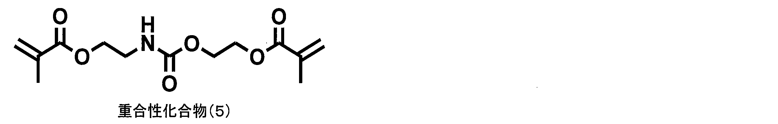
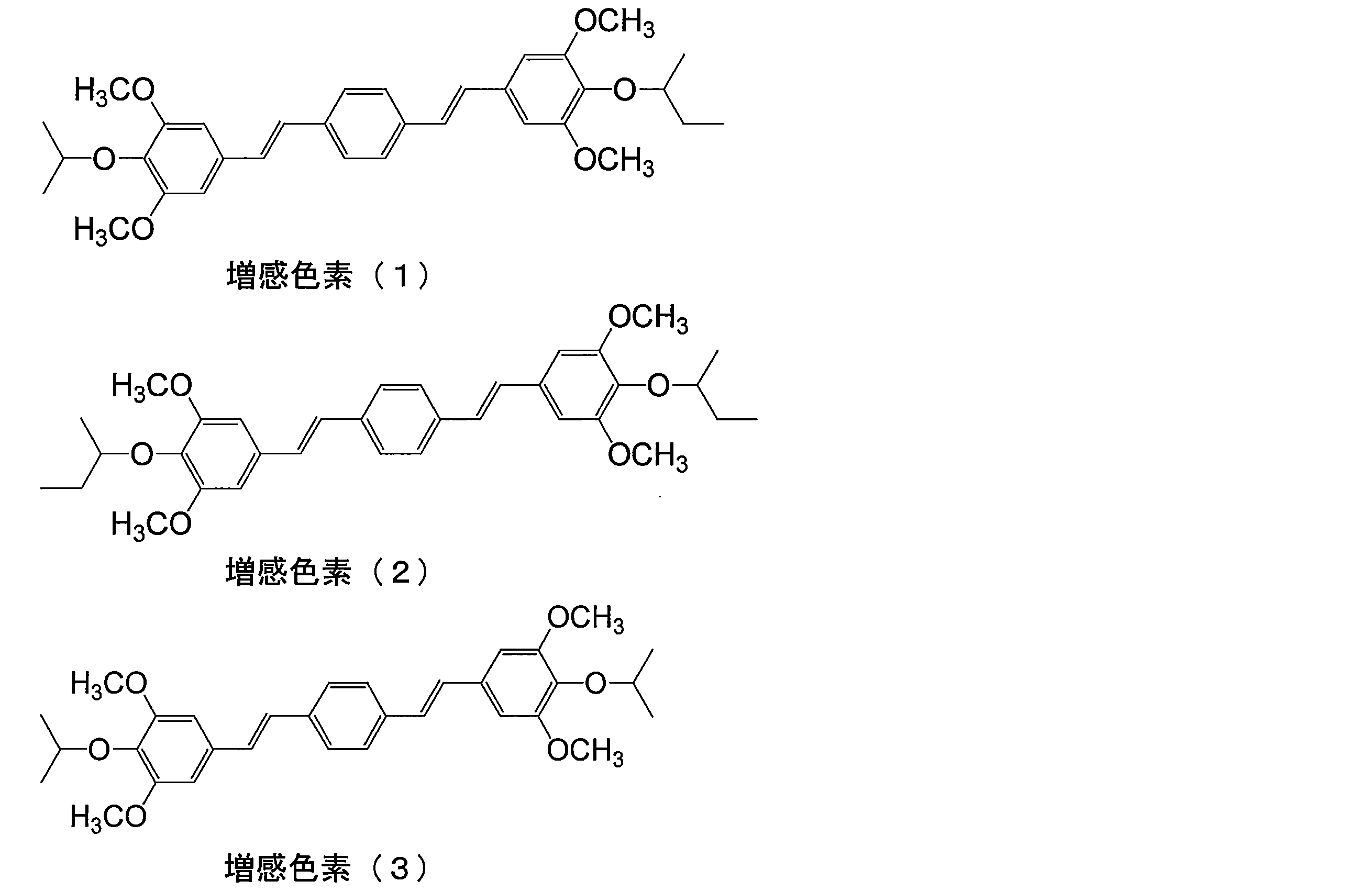

各感光層液において用いたポリビニルアセタールバインダーの種類を下記に示す。また、(A)重合性化合物について、上記重合性化合物(1)~(3)のいずれか1種以上を用いた。感光層塗布液(4)は、感光層塗布液(1)から重合性化合物(2)の添加分を、重合性化合物(1)に置き換えて調整した。感光層塗布液(50)は、 感光層塗布液(1)から重合性化合物(1)及び(2)の添加分を、下記重合性化合物(3)に置き換えて調整した。感光層塗布液52は、(C)ポリビニルアセタールバインダーポリマーの添加分を、バインダーポリマー(1)(アクリル樹脂)に置き換えて調整した。


<サーマル>
〔感光層(53)~(60)の形成〕
下記組成の感光層塗布液2‘を上記下塗り層の上にバー塗布した後、100℃で60秒間オーブン乾燥し、感光層2を形成した。感光層塗布液2’は下記感光層塗布液(2)および疎水化前駆体液(1)を塗布直前に混合し攪拌することにより調製した。
〔感光層(53)~(60)の形成〕
下記組成の感光層塗布液2‘を上記下塗り層の上にバー塗布した後、100℃で60秒間オーブン乾燥し、感光層2を形成した。感光層塗布液2’は下記感光層塗布液(2)および疎水化前駆体液(1)を塗布直前に混合し攪拌することにより調製した。
<感光層塗布液(53)~(60)>
・下記バインダーポリマー(1)((D)アクリル樹脂)(重量平均分子量:5万)
0.032g
・上記表に示すポリビニルアセタールバインダーポリマー 0.19g
・下記赤外線吸収染料(1) 0.030g
・下記ラジカル発生剤(1) 0.162g
・上記重合性化合物(1) 0.17g
(PLEX6661-O、デグサジャパン製)
・上記重合性化合物(2) 0.51g
・パイオニンA-20(竹本油脂(株)製) 0.055g
・下記感脂化剤(1) 0.044g
・上記フッ素系界面活性剤(1) 0.008g
・メチルエチルケトン 1.091g
・1-メトキシ-2-プロパノール 8.609g
・下記バインダーポリマー(1)((D)アクリル樹脂)(重量平均分子量:5万)
0.032g
・上記表に示すポリビニルアセタールバインダーポリマー 0.19g
・下記赤外線吸収染料(1) 0.030g
・下記ラジカル発生剤(1) 0.162g
・上記重合性化合物(1) 0.17g
(PLEX6661-O、デグサジャパン製)
・上記重合性化合物(2) 0.51g
・パイオニンA-20(竹本油脂(株)製) 0.055g
・下記感脂化剤(1) 0.044g
・上記フッ素系界面活性剤(1) 0.008g
・メチルエチルケトン 1.091g
・1-メトキシ-2-プロパノール 8.609g
<疎水化前駆体液(1)>
・下記疎水化前駆体水分散液(1) 2.640g
・蒸留水 2.425g
・下記疎水化前駆体水分散液(1) 2.640g
・蒸留水 2.425g

(疎水化前駆体水分散液(1)の製造)
1000mlの4つ口フラスコに撹拌機、温度計、滴下ロート、窒素導入管、還流冷却器を施し、窒素ガスを導入して脱酸素を行いつつ蒸留水(350mL)を加えて内温が80℃となるまで加熱した。分散剤としてドデシル硫酸ナトリウム(1.5g)添加し、さらに開始剤として過硫化アンモニウム(0.45g)を添加し、次いでグリシジルメタクリレート(45.0g)とスチレン(45.0g)との混合物を滴下ロートから約1時間かけて滴下した。滴下終了後5時間そのまま反応を続けた後、水蒸気蒸留で未反応単量体を除去した。その後冷却しアンモニア水でpH6に調整し、最後に不揮発分が15質量%となるように純水を添加してポリマー微粒子からなる疎水化前駆体水分散液(1)を得た。このポリマー微粒子の粒子サイズ分布は、粒子サイズ60nmに極大値を有していた。
1000mlの4つ口フラスコに撹拌機、温度計、滴下ロート、窒素導入管、還流冷却器を施し、窒素ガスを導入して脱酸素を行いつつ蒸留水(350mL)を加えて内温が80℃となるまで加熱した。分散剤としてドデシル硫酸ナトリウム(1.5g)添加し、さらに開始剤として過硫化アンモニウム(0.45g)を添加し、次いでグリシジルメタクリレート(45.0g)とスチレン(45.0g)との混合物を滴下ロートから約1時間かけて滴下した。滴下終了後5時間そのまま反応を続けた後、水蒸気蒸留で未反応単量体を除去した。その後冷却しアンモニア水でpH6に調整し、最後に不揮発分が15質量%となるように純水を添加してポリマー微粒子からなる疎水化前駆体水分散液(1)を得た。このポリマー微粒子の粒子サイズ分布は、粒子サイズ60nmに極大値を有していた。
粒子サイズ分布は、ポリマー微粒子の電子顕微鏡写真を撮影し、写真上で微粒子の粒子サイズを総計で5000個測定し、得られた粒子サイズ測定値の最大値から0の間を対数目盛で50分割して各粒子サイズの出現頻度をプロットして求めた。なお非球形粒子については写真上の粒子面積と同一の粒子面積を持つ球形粒子の粒子サイズ値を粒子サイズとした。

<保護層1の形成>
上記で作成した各感光層の表面に、下記組成よりなる保護層塗布液(1)をバーを用いて塗布した後、125℃、70秒で間乾燥して保護層を形成した。
上記で作成した各感光層の表面に、下記組成よりなる保護層塗布液(1)をバーを用いて塗布した後、125℃、70秒で間乾燥して保護層を形成した。
保護層塗布液(1)
・PVA-205 0.658g
(部分加水分解ポリビニルアルコール、クラレ(株)製、鹸化度=86.5-89.5モル%、粘度=4.6-5.4mPa・s(20℃、4質量%水溶液中))
・PVA-105 0.142g
(完全加水分解ポリビニルアルコール、クラレ(株)製、鹸化度=98.0-99.0モル%、粘度=5.2-6.0mPa・s(20℃、4質量%水溶液中))
・ポリ(ビニルピロリドン/酢酸ビニル(1/1))(分子量7万)
0.001g
・界面活性剤(エマレックス710、日本エマルジョン(株)製)
0.002g
・水 13g
・PVA-205 0.658g
(部分加水分解ポリビニルアルコール、クラレ(株)製、鹸化度=86.5-89.5モル%、粘度=4.6-5.4mPa・s(20℃、4質量%水溶液中))
・PVA-105 0.142g
(完全加水分解ポリビニルアルコール、クラレ(株)製、鹸化度=98.0-99.0モル%、粘度=5.2-6.0mPa・s(20℃、4質量%水溶液中))
・ポリ(ビニルピロリドン/酢酸ビニル(1/1))(分子量7万)
0.001g
・界面活性剤(エマレックス710、日本エマルジョン(株)製)
0.002g
・水 13g
<実施例 1~42、70~75、比較例1~8-フォトポリ弱アルカリ現像>
<実施例43~47、比較例 9~11フォトポリ強アルカリ現像>
<実施例43~47、比較例 9~11フォトポリ強アルカリ現像>
(1)露光、現像および印刷
前記の平版印刷版原版を、FUJIFILM Electronic Imaging Ltd 製Violet半導体レーザープレートセッターVx9600(InGaN系半導体レーザー405nm±10nm発光/出力30mWを搭載)により画像露光を実施した。画像描画は、解像度2438dpiで、富士フイルム(株)製FMスクリーン(TAFFETA 20)を用い、50%の平網を、版面露光量0.05mJ/cm2で実施した。
次いで、下記組成の現像液1を用い、図1に示す構造の自動現像処理機にて、プレヒート100℃、10秒、現像液中への浸漬時間(現像時間)が、20秒となる搬送速度にて現像処理を実施した。但し、現像液2を用いた際は、現像後乾燥工程を行う前に、水洗を行った。
次いで、現像後の平版印刷版を、ハイデルベルグ社製印刷機SOR-Mに取り付け、湿し水(EU-3(富士写真フイルム(株)製エッチ液)/水/イソプロピルアルコール=1/89/10(容量比))とTRANS-G(N)墨インキ(大日本インキ化学工業(株)製)とを用い、毎時6000枚の印刷速度で印刷を行った。
<現像液1>
水 88.6g
ノニオン系界面活性剤(W-1) 2.4g
ノニオン系界面活性剤(W-2) 2.4g
ノニオン系界面活性剤(エマレックス710、日本エマルジョン(株)製)
1.0g
フェノキシプロパノール 1.0g
オクタノール 0.6g
N-(2-ヒドロキシエチル)モルホリン 1.0g
トリエタノールアミン 0.5g
グルコン酸ナトリウム 1.0g
クエン酸3ナトリウム 0.5g
エチレンジアミンテトラアセテート4ナトリウム塩 0.05g
ポリスチレンスルホン酸(Versa TL77(30%溶液)、Alco c hemical社製) 1 .0g
*上記組成の現像液に、リン酸を添加し、pHを7.0に調整した。

<現像液2>
・水酸化カリウム 0.15g
・ニューコールB13(日本乳化剤製) 5.0g
・キレスト400(キレート剤)(キレスト(株)製) 0.1g
・蒸留水 94.75g
(pH:12.05)
・水酸化カリウム 0.15g
・ニューコールB13(日本乳化剤製) 5.0g
・キレスト400(キレート剤)(キレスト(株)製) 0.1g
・蒸留水 94.75g
(pH:12.05)
得られた平版印刷版を、ハイデルベルグ社製印刷機SOR-Mに取り付け、湿し水(EU-3(富士フイルム(株)製エッチ液)/水/イソプロピルアルコール=1/89/10(容量比))とTRANS-G(N)墨インキ(大日本インキ化学工業(株)製)とを用い、毎時6000枚の印刷速度で印刷を行った。
〔評価〕
各平版印刷版原版について、耐刷性、現像液ランニング性、水幅を下記のように評価した。結果を下記表に示す。
各平版印刷版原版について、耐刷性、現像液ランニング性、水幅を下記のように評価した。結果を下記表に示す。
<耐刷性>
印刷枚数の増加にともない、徐々に感光層が磨耗しインキ受容性が低下するため、印刷用紙におけるインキ濃度が低下した。同一露光量で露光した印刷版において、インキ濃度(反射濃度)が印刷開始時よりも0.1低下したときの印刷枚数により、耐刷性を評価した。
印刷枚数の増加にともない、徐々に感光層が磨耗しインキ受容性が低下するため、印刷用紙におけるインキ濃度が低下した。同一露光量で露光した印刷版において、インキ濃度(反射濃度)が印刷開始時よりも0.1低下したときの印刷枚数により、耐刷性を評価した。
<現像液ランニング性>
上記現像工程を、現像液を交換せずに繰り返して行い、得られた平版印刷版の非画像部のシアン濃度をマクベス濃度計により測定した。上記現像条件において、アルミニウム支持体のシアン濃度と同等のシアン濃度が得られなくなるまで試験を繰り返し、その時点までに処理した印刷版原版の総面積を現像液ランニング性として評価した。
上記現像工程を、現像液を交換せずに繰り返して行い、得られた平版印刷版の非画像部のシアン濃度をマクベス濃度計により測定した。上記現像条件において、アルミニウム支持体のシアン濃度と同等のシアン濃度が得られなくなるまで試験を繰り返し、その時点までに処理した印刷版原版の総面積を現像液ランニング性として評価した。
<水幅>
印刷時に湿し水目盛り(0~100)を種々に変更して印刷を行い、良好な画像が得られた目盛りの上限値から下限値を引いた値を水幅として評価した。
印刷時に湿し水目盛り(0~100)を種々に変更して印刷を行い、良好な画像が得られた目盛りの上限値から下限値を引いた値を水幅として評価した。

上記表から明らかなとおり、本発明の平版印刷版原版を用いた場合、耐刷性、現像液ランニング性および水幅メモリのいずれにも優れたものが得られた。この現象は、特に、重合性化合物として、ウレタン結合を有する化合物を含む場合に効果的であり、ウレア結合を有する化合物を含む場合にさらに効果的であった。
一方、ポリビニルアセタール樹脂が有する架橋性基として、(メタ)アクリロイル基以外のものを含む場合(比較例4、5)、(メタ)アクリロイル基を用いていても、主鎖との間に、アルキレン基を含む場合(比較例1~3)では、本発明の効果は達成できなかった。さらに、架橋性基を有さないポリビニルアセタール樹脂を用いた場合(比較例6)、アクリル樹脂を含まない場合(比較例7)、ポリビニルアセタール樹脂を用いない場合(比較例8)では、本発明の効果は得られなかった。
一方、ポリビニルアセタール樹脂が有する架橋性基として、(メタ)アクリロイル基以外のものを含む場合(比較例4、5)、(メタ)アクリロイル基を用いていても、主鎖との間に、アルキレン基を含む場合(比較例1~3)では、本発明の効果は達成できなかった。さらに、架橋性基を有さないポリビニルアセタール樹脂を用いた場合(比較例6)、アクリル樹脂を含まない場合(比較例7)、ポリビニルアセタール樹脂を用いない場合(比較例8)では、本発明の効果は得られなかった。
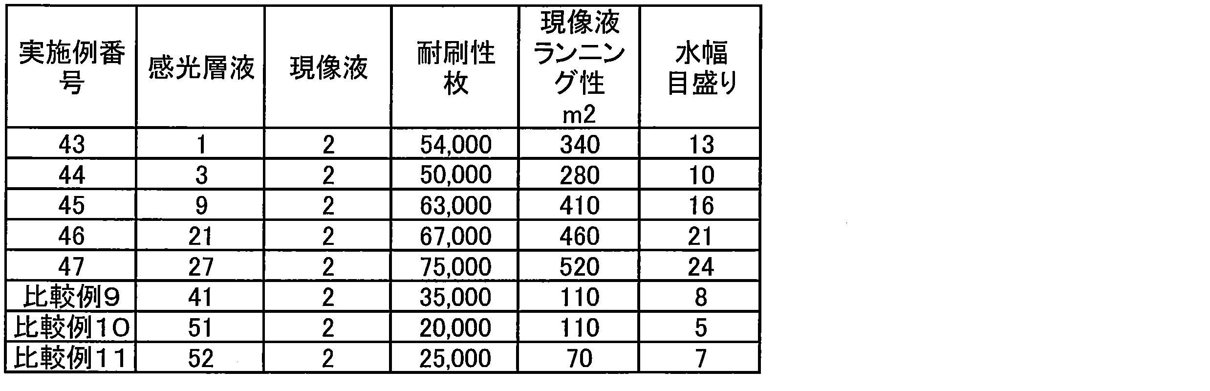
上記表から明らかなとおり、本発明の平版印刷版原版を用いた場合、弱アルカリ現像液を用いた場合だけではなく、強アルカリ現像液を用いても、耐刷性、現像液ランニング性および水幅メモリのいずれにも優れたものが得られた。
<実施例53~62、比較例 15~20-サーマル弱アルカリ・強アルカリ現像>
〔露光、現像および印刷〕
下記に示す各平版印刷版原版を、Creo社製Trendsetter3244VX(水冷式40W赤外線半導体レーザー(830nm)搭載)にて、出力9W、外面ドラム回転数210rpm、解像度2、400dpiの条件で50%平網の画像露光を行った。次いで、各現像液を用い、図2に示す構造の自動現像処理機にて、プレヒート部での版面到達温度が100℃となるヒーター設定、現像液中への浸漬時間(現像時間)が20秒となる搬送速度にて現像処理を実施した。但し、現像液2を用いた際は、現像後乾燥工程を行う前に、水洗を行った。
〔露光、現像および印刷〕
下記に示す各平版印刷版原版を、Creo社製Trendsetter3244VX(水冷式40W赤外線半導体レーザー(830nm)搭載)にて、出力9W、外面ドラム回転数210rpm、解像度2、400dpiの条件で50%平網の画像露光を行った。次いで、各現像液を用い、図2に示す構造の自動現像処理機にて、プレヒート部での版面到達温度が100℃となるヒーター設定、現像液中への浸漬時間(現像時間)が20秒となる搬送速度にて現像処理を実施した。但し、現像液2を用いた際は、現像後乾燥工程を行う前に、水洗を行った。
得られた平版印刷版を、ハイデルベルグ社製印刷機SOR-Mに取り付け、湿し水(EU-3(富士フイルム(株)製エッチ液)/水/イソプロピルアルコール=1/89/10(容量比))とTRANS-G(N)墨インキ(大日本インキ化学工業(株)製)とを用い、毎時6000枚の印刷速度で印刷を行った。
各平版印刷版原版について耐刷性、現像液ランニング性、水幅を実施例1と同様にして評価した。結果を下記表に示す。

上記表から明らかなとおり、本発明の平版印刷版原版を用いた場合、サーマル現像を行っても、耐刷性、現像液ランニング性および水幅メモリのいずれにも優れたものが得られた。
<実施例48~52、比較例 12~14-サーマル機上現像型>
〔露光、現像および印刷〕
下記表に示す各平版印刷版原版を、赤外線半導体レーザー搭載の富士フイルム(株)製Luxel PLATESETTER T-6000IIIにて、外面ドラム回転数1000rpm、レーザー出力70%、解像度2400dpiの条件で露光した。露光画像にはベタ画像および20μmドットFMスクリーンの50%網点チャートを含むようにした。
露光済み平版印刷版原版を現像処理することなく、(株)小森コーポレーション製印刷機LITHRONE26の版胴に取り付けた。Ecolity-2(富士フイルム(株)製)/水道水=2/98(容量比)の湿し水とValues-G(N)墨インキ(大日本インキ化学工業(株)製)とを用い、LITHRONE26の標準自動印刷スタート方法で湿し水とインキとを供給して機上現像した後、毎時10000枚の印刷速度で、特菱アート(76.5kg)紙に印刷を100枚行った
〔評価〕
各平版印刷版原版について、耐刷性、水幅目盛りを実施例1と同様にして評価した。
また、現像液ランニング性については、機上現像を湿し水を交換せずに繰り返し機上現像を行った。上記現像条件において、交換直後の湿し水を用いた場合の機上現像に要した印刷枚数内で機上現像が完了しなくなるまで試験を繰り返し、その時点までに処理した印刷版原版の総面積を現像液ランニング性として評価した。下記のように評価した。結果を下記表に示す。
各平版印刷版原版について、耐刷性、水幅目盛りを実施例1と同様にして評価した。
また、現像液ランニング性については、機上現像を湿し水を交換せずに繰り返し機上現像を行った。上記現像条件において、交換直後の湿し水を用いた場合の機上現像に要した印刷枚数内で機上現像が完了しなくなるまで試験を繰り返し、その時点までに処理した印刷版原版の総面積を現像液ランニング性として評価した。下記のように評価した。結果を下記表に示す。

上記表から明らかなとおり、本発明の平版印刷版原版を用いた場合、サーマル机上型現像を行っても、耐刷性、現像液ランニング性および水幅メモリのいずれにも優れたものが得られた。
Claims (13)
- 支持体上に光重合性層を有し、該光重合性層が、(A)重合性化合物、(B)重合開始剤、(C)一般式(I-c)、一般式(I-b)および一般式(I-a)で表される繰り返し単位の少なくとも1種を有するポリビニルアセタールバインダー、ならびに(D)アクリル樹脂を含むバインダーを含む平版印刷版原版。

- 前記(C)バインダーが、下記一般式(II)、一般式(III)、一般式(IV)および一般式(V)のいずれかで表される繰り返し単位の少なくとも1種を有するポリビニルアセタールバインダーである、請求項1に記載の平版印刷版原版。

- 前記(A)重合性化合物が、ウレタン結合を有する請求項1または2に記載の平版印刷版原版。
- 前記(A)重合性化合物が、さらにウレア結合を有する請求項1~3のいずれか1項に記載の平版印刷版原版。
- 前記(A)重合性化合物が、ウレタンを結合および/またはウレア結合を有する(メタ)アクリレートである、請求項1または2に記載の平版印刷版原版。
- 前記(A)重合性化合物が、多官能化合物である、請求項1~5のいずれか1項に記載の平版印刷版原版。
- 前記(A)重合性化合物の少なくとも1種が下記で表される化合物である、請求項1または2に記載の平版印刷版原版。

- 前記ポリビニルアセタールバインダーが、一般式(I-c)、一般式(I-b)および一般式(I-a)で表される繰り返し単位の少なくとも1種と、下記繰り返し単位(1)~(3)と、酸基とを含むポリビニルアセタールバインダーである、請求項1~7のいずれか1項に記載の平版印刷版原版。

- 請求項1~8のいずれか1項に記載の平版印刷版原版を、画像様に露光する工程と、露光した前記平版印刷版原版を、pHが2~14の現像液の存在下で、非露光部の前記感光層を除去する工程を含むことを特徴とする平版印刷版の製造方法。
- 前記露光工程で、露光後に前駆体を予備加熱装置内で80℃以上の温度で加熱することを特徴とする、請求項9に記載の平版印刷版の製造方法。
- 前記現像工程において、さらに界面活性剤を含有する前記現像液の存在下、非露光部の感光層と前記保護層とを同時に除去する工程を含む(但し、水洗工程を含まない)、ことを特徴とする請求項9または10に記載の平版印刷版の製造方法。
- 前記現像液のpHを、2.0~10.0に制御する工程を含むことを特徴とする、請求項9~11のいずれか1項に記載の平版印刷版の製造方法。
- 請求項1~8のいずれか1項に記載の平版印刷版原版を、画像様に露光する工程と、印刷機上で印刷インキと湿し水を供給して非露光部の前記感光層を除去する工程とを含むことを特徴とする平版印刷版の製造方法。
Priority Applications (3)
| Application Number | Priority Date | Filing Date | Title |
|---|---|---|---|
| CN201380011087.6A CN104136995A (zh) | 2012-02-27 | 2013-02-15 | 平版印刷版原版及平版印刷版的制作方法 |
| EP13754776.6A EP2821854B1 (en) | 2012-02-27 | 2013-02-15 | Lithographic printing plate precursors and processes for preparing lithographic printing plates |
| US14/467,613 US9348225B2 (en) | 2012-02-27 | 2014-08-25 | Lithographic printing plate precursors and processes for preparing lithographic printing plates |
Applications Claiming Priority (2)
| Application Number | Priority Date | Filing Date | Title |
|---|---|---|---|
| JP2012-040056 | 2012-02-27 | ||
| JP2012040056A JP5711168B2 (ja) | 2012-02-27 | 2012-02-27 | 平版印刷版原版および平版印刷版の作製方法 |
Related Child Applications (1)
| Application Number | Title | Priority Date | Filing Date |
|---|---|---|---|
| US14/467,613 Continuation US9348225B2 (en) | 2012-02-27 | 2014-08-25 | Lithographic printing plate precursors and processes for preparing lithographic printing plates |
Publications (1)
| Publication Number | Publication Date |
|---|---|
| WO2013129126A1 true WO2013129126A1 (ja) | 2013-09-06 |
Family
ID=49082328
Family Applications (1)
| Application Number | Title | Priority Date | Filing Date |
|---|---|---|---|
| PCT/JP2013/053616 WO2013129126A1 (ja) | 2012-02-27 | 2013-02-15 | 平版印刷版原版および平版印刷版の作製方法 |
Country Status (5)
| Country | Link |
|---|---|
| US (1) | US9348225B2 (ja) |
| EP (1) | EP2821854B1 (ja) |
| JP (1) | JP5711168B2 (ja) |
| CN (1) | CN104136995A (ja) |
| WO (1) | WO2013129126A1 (ja) |
Families Citing this family (10)
| Publication number | Priority date | Publication date | Assignee | Title |
|---|---|---|---|---|
| WO2006094079A2 (en) * | 2005-03-03 | 2006-09-08 | 3M Innovative Properties Company | Thermosettable adhesive tape, articles and methods |
| JP5715975B2 (ja) * | 2012-02-29 | 2015-05-13 | 富士フイルム株式会社 | 平版印刷版原版および平版印刷版の製造方法 |
| KR101958691B1 (ko) * | 2014-11-27 | 2019-03-15 | 후지필름 가부시키가이샤 | 제거액, 이를 이용한 제거 방법 및 반도체 기판 제품의 제조 방법 |
| CN108778744A (zh) * | 2016-03-16 | 2018-11-09 | 爱克发有限公司 | 加工平版印刷版的方法和设备 |
| CN106444305A (zh) * | 2016-10-09 | 2017-02-22 | 温州市行者新材料有限公司 | 耐uv油墨uv‑ctp版显影液 |
| CN110719847B (zh) * | 2017-05-31 | 2021-08-31 | 富士胶片株式会社 | 平版印刷版原版及平版印刷版的制作方法 |
| CN111683820B (zh) * | 2018-01-31 | 2022-06-17 | 富士胶片株式会社 | 平版印刷版原版及平版印刷版的制作方法 |
| WO2020026808A1 (ja) * | 2018-07-30 | 2020-02-06 | 富士フイルム株式会社 | 機上現像型平版印刷版原版、平版印刷版の作製方法、及び、平版印刷方法 |
| WO2020209143A1 (ja) * | 2019-04-12 | 2020-10-15 | 富士フイルム株式会社 | フレキソ印刷版用水性現像液およびフレキソ印刷版の製造方法 |
| EP3778253A1 (en) * | 2019-08-13 | 2021-02-17 | Agfa Nv | Method for processing a lithographic printing plate |
Citations (77)
| Publication number | Priority date | Publication date | Assignee | Title |
|---|---|---|---|---|
| US2850445A (en) | 1955-01-19 | 1958-09-02 | Oster Gerald | Photopolymerization |
| JPS4420189B1 (ja) | 1965-06-03 | 1969-08-30 | ||
| JPS4841708B1 (ja) | 1970-01-13 | 1973-12-07 | ||
| JPS5137193A (ja) | 1974-09-25 | 1976-03-29 | Toyo Boseki | |
| EP0024629A2 (en) | 1979-08-14 | 1981-03-11 | E.I. Du Pont De Nemours And Company | Photoimaging composition comprising a 2,4,5-triphenylimidazolyl dimer and at least one compound selected from the group consisting of a leuco dye and a polymerizable ethylenically unsaturated monomer |
| JPS5617654B2 (ja) | 1970-12-28 | 1981-04-23 | ||
| US4410621A (en) | 1981-04-03 | 1983-10-18 | Toyo Boseki Kabushiki Kaisha | Photosensitive resin containing a combination of diphenyl-imiazolyl dimer and a heterocyclic mercaptan |
| JPS5849860B2 (ja) | 1973-12-07 | 1983-11-07 | ヘキスト アクチェンゲゼルシャフト | コウジユウゴウセイフクシヤザイリヨウ |
| EP0107792A1 (en) | 1982-09-27 | 1984-05-09 | Mitsubishi Kasei Corporation | Photopolymerizable compositions |
| JPS6239417B2 (ja) | 1978-05-20 | 1987-08-22 | Hoechst Ag | |
| JPS6239418B2 (ja) | 1978-05-20 | 1987-08-22 | Hoechst Ag | |
| US4708925A (en) | 1984-12-11 | 1987-11-24 | Minnesota Mining And Manufacturing Company | Photosolubilizable compositions containing novolac phenolic resin |
| GB2192792A (en) | 1986-07-21 | 1988-01-27 | Smith & Nephew Ass | Wound dressing |
| JPH0216765B2 (ja) | 1980-09-29 | 1990-04-18 | Hoechst Ag | |
| JPH0232293B2 (ja) | 1980-12-22 | 1990-07-19 | Hoechst Ag | |
| JPH02304441A (ja) | 1989-05-18 | 1990-12-18 | Fuji Photo Film Co Ltd | 感光性平版印刷版 |
| JPH0545885A (ja) | 1991-08-19 | 1993-02-26 | Fuji Photo Film Co Ltd | 感光性平版印刷版 |
| JPH0635174A (ja) | 1992-07-16 | 1994-02-10 | Fuji Photo Film Co Ltd | 感光性平版印刷版およびその処理方法 |
| JPH08276558A (ja) | 1995-02-06 | 1996-10-22 | Fuji Photo Film Co Ltd | ネガ型画像記録材料 |
| JPH09123387A (ja) | 1995-10-24 | 1997-05-13 | Agfa Gevaert Nv | 印刷機上現像を含む平版印刷版の製造方法 |
| JPH09131850A (ja) | 1995-10-24 | 1997-05-20 | Agfa Gevaert Nv | 印刷機上現像を含む平版印刷版の製造方法 |
| JPH09171249A (ja) | 1995-11-09 | 1997-06-30 | Agfa Gevaert Nv | 感熱性像形成要素およびそれを用いて印刷版を製造する方法 |
| JPH09171250A (ja) | 1995-11-09 | 1997-06-30 | Agfa Gevaert Nv | 感熱性像形成要素およびそれらを用いて印刷版を製造する方法 |
| JPH10282679A (ja) | 1997-04-08 | 1998-10-23 | Fuji Photo Film Co Ltd | ネガ型感光性平版印刷版 |
| EP0931647A1 (en) | 1998-01-23 | 1999-07-28 | Agfa-Gevaert N.V. | A heat sensitive element and a method for producing lithographic plates therewith |
| JP2000211262A (ja) | 1999-01-28 | 2000-08-02 | Asahi Chem Ind Co Ltd | 感熱平版印刷原版 |
| EP1025992A1 (en) | 1999-02-02 | 2000-08-09 | Agfa-Gevaert N.V. | A method for making positive printing plates |
| JP2001133969A (ja) | 1999-11-01 | 2001-05-18 | Fuji Photo Film Co Ltd | ネガ型平版印刷版原版 |
| JP2001166491A (ja) | 1999-09-29 | 2001-06-22 | Fuji Photo Film Co Ltd | 平版印刷版用支持体及びそれを用いた平版印刷版用原版 |
| JP2001277740A (ja) | 2000-01-27 | 2001-10-10 | Fuji Photo Film Co Ltd | 平版印刷版用原版 |
| JP2001277742A (ja) | 2000-01-27 | 2001-10-10 | Fuji Photo Film Co Ltd | 平版印刷版用原版 |
| WO2002004210A1 (en) | 2000-07-06 | 2002-01-17 | Cabot Corporation | Printing plates comprising modified pigment products |
| JP2002029162A (ja) | 2000-07-13 | 2002-01-29 | Fuji Photo Film Co Ltd | 平版印刷用原板 |
| JP2002046361A (ja) | 2000-08-01 | 2002-02-12 | Fuji Photo Film Co Ltd | 平版印刷用原板 |
| JP2002137562A (ja) | 2000-11-01 | 2002-05-14 | Fuji Photo Film Co Ltd | 平版印刷版用原版 |
| JP2002278057A (ja) | 2001-01-15 | 2002-09-27 | Fuji Photo Film Co Ltd | ネガ型画像記録材料及びシアニン色素 |
| JP2002326470A (ja) | 2001-02-28 | 2002-11-12 | Fuji Photo Film Co Ltd | 平版印刷版原版 |
| JP2003063166A (ja) | 2001-06-11 | 2003-03-05 | Fuji Photo Film Co Ltd | 平版印刷版用支持体 |
| EP1349006A1 (en) | 2002-03-28 | 2003-10-01 | AGFA-GEVAERT naamloze vennootschap | Photopolymerizable composition sensitized for the wavelength range from 300 to 450 nm. |
| JP2004276603A (ja) | 2003-02-25 | 2004-10-07 | Fuji Photo Film Co Ltd | 平版印刷版用支持体 |
| EP1491356A2 (en) | 2003-06-25 | 2004-12-29 | Fuji Photo Film Co., Ltd. | Lithographic printing plate precursor and lithographic printing method |
| US20050008971A1 (en) | 2003-07-10 | 2005-01-13 | Tomoyoshi Mitsumoto | Lithographic printing plate precursor and lithographic printing method |
| WO2005029187A1 (en) | 2003-09-22 | 2005-03-31 | Agfa-Gevaert | Photopolymerizable composition. |
| JP2005125749A (ja) | 2003-09-30 | 2005-05-19 | Fuji Photo Film Co Ltd | 平版印刷版原版および平版印刷方法 |
| JP2005238816A (ja) | 2003-07-22 | 2005-09-08 | Fuji Photo Film Co Ltd | 平版印刷版原版および平版印刷方法 |
| JP2006106700A (ja) | 2004-08-24 | 2006-04-20 | Fuji Photo Film Co Ltd | 平版印刷版の作製方法、平版印刷版原版および平版印刷方法 |
| JP2006215263A (ja) | 2005-02-03 | 2006-08-17 | Fuji Photo Film Co Ltd | 平版印刷版原版 |
| JP2006239867A (ja) | 2005-02-28 | 2006-09-14 | Fuji Photo Film Co Ltd | 平版印刷版原版および平版印刷方法 |
| JP2006256132A (ja) * | 2005-03-17 | 2006-09-28 | Konica Minolta Medical & Graphic Inc | ネガ型感光性平版印刷版材料及び平版印刷版の製版方法 |
| JP2006297907A (ja) | 2005-02-28 | 2006-11-02 | Fuji Photo Film Co Ltd | 平版印刷版原版、平版印刷版原版の製造方法および平版印刷方法 |
| JP2007050660A (ja) | 2005-08-19 | 2007-03-01 | Fujifilm Corp | 平版印刷版原版および平版印刷方法 |
| JP2007058170A (ja) | 2005-07-25 | 2007-03-08 | Fujifilm Corp | 平版印刷版の作製方法および平版印刷版原版 |
| JP2007506125A (ja) | 2003-09-22 | 2007-03-15 | アグフア−ゲヴエルト | 光重合体印刷版前駆体 |
| JP2007118579A (ja) | 2005-09-27 | 2007-05-17 | Fujifilm Corp | 平版印刷版原版および平版印刷方法 |
| WO2007057348A1 (en) | 2005-11-18 | 2007-05-24 | Agfa Graphics Nv | Method of making a lithographic printing plate |
| WO2007057442A2 (en) | 2005-11-18 | 2007-05-24 | Agfa Graphics Nv | Method of making a photopolymer printing plate |
| JP2007171406A (ja) | 2005-12-20 | 2007-07-05 | Fujifilm Corp | 平版印刷版の作製方法および平版印刷版原版 |
| JP2007206216A (ja) | 2006-01-31 | 2007-08-16 | Fujifilm Corp | 平版印刷版の作製方法および平版印刷版原版 |
| JP2007206217A (ja) | 2006-01-31 | 2007-08-16 | Fujifilm Corp | 平版印刷版の作製方法および平版印刷版原版 |
| JP2007225701A (ja) | 2006-02-21 | 2007-09-06 | Fujifilm Corp | 平版印刷版の作製方法 |
| JP2007225702A (ja) | 2006-02-21 | 2007-09-06 | Fujifilm Corp | 平版印刷版の作製方法 |
| JP2007316582A (ja) | 2005-12-02 | 2007-12-06 | Fujifilm Corp | 平版印刷版の作製方法および平版印刷版原版 |
| JP2007328243A (ja) | 2006-06-09 | 2007-12-20 | Fujifilm Corp | 平版印刷版の作製方法および平版印刷版原版 |
| JP2008203359A (ja) | 2007-02-16 | 2008-09-04 | Fujifilm Corp | 平版印刷版の作製方法 |
| JP2008213177A (ja) | 2007-02-28 | 2008-09-18 | Fujifilm Corp | 平版印刷版原版 |
| JP2008276166A (ja) | 2006-09-29 | 2008-11-13 | Fujifilm Corp | 平版印刷版用現像処理液及び平版印刷版の製版方法 |
| JP2008284858A (ja) | 2007-05-21 | 2008-11-27 | Fujifilm Corp | 平版印刷版原版、及びそれを用いた印刷方法 |
| JP2009516602A (ja) | 2005-11-21 | 2009-04-23 | アグファ・グラフィクス・エヌヴィ | 平版印刷版を製造する方法 |
| JP2009090645A (ja) | 2007-09-20 | 2009-04-30 | Fujifilm Corp | 平版印刷版原版、及びそれを用いた印刷方法 |
| JP2009208458A (ja) | 2007-06-21 | 2009-09-17 | Fujifilm Corp | 平版印刷版原版および平版印刷方法 |
| JP2009258719A (ja) * | 2008-03-27 | 2009-11-05 | Fujifilm Corp | 平版印刷版原版及びこれを用いた平版印刷版の作製方法 |
| JP2010105382A (ja) * | 2008-09-30 | 2010-05-13 | Fujifilm Corp | 平版印刷版原版、平版印刷版の製版方法及び重合性モノマー |
| JP2010139551A (ja) | 2008-12-09 | 2010-06-24 | Nippe Graphics Kk | 感光性平版印刷用アルカリ現像液および平版印刷版の製版方法 |
| JP2011191558A (ja) * | 2010-03-15 | 2011-09-29 | Fujifilm Corp | 平版印刷版の作製方法 |
| JP2011221522A (ja) * | 2010-03-26 | 2011-11-04 | Fujifilm Corp | 平版印刷版の作製方法 |
| JP2011251431A (ja) | 2010-05-31 | 2011-12-15 | Fujifilm Corp | 平版印刷版原版及びその製版方法 |
| JP2012031400A (ja) | 2010-06-30 | 2012-02-16 | Fujifilm Corp | 新規な重合性組成物及びそれに用いる重合性化合物、並びに新規な重合性組成物を用いた画像形成材料及び平版印刷版原版 |
Family Cites Families (7)
| Publication number | Priority date | Publication date | Assignee | Title |
|---|---|---|---|---|
| JPS5515697B1 (ja) * | 1971-07-02 | 1980-04-25 | ||
| US4221859A (en) * | 1976-05-04 | 1980-09-09 | Ball Corporation | Photopolymerizable composition with oxalic acid photoinitiator |
| KR970005116B1 (ko) * | 1987-05-28 | 1997-04-12 | 후지샤신 필름 가부시끼가이샤 | 판재 소부장치 |
| DE3719871A1 (de) * | 1987-06-13 | 1988-12-29 | Basf Ag | Durch photopolymerisation vernetzbare heisspraegeplatten |
| JP4248137B2 (ja) * | 2000-11-22 | 2009-04-02 | 富士フイルム株式会社 | ネガ型感光性平版印刷版 |
| US7910286B2 (en) * | 2005-01-26 | 2011-03-22 | Fujifilm Corporation | Lithographic printing plate precursor, lithographic printing method and packaged body of lithographic printing plate precursors |
| JP2007245478A (ja) * | 2006-03-15 | 2007-09-27 | Fujifilm Corp | 赤外線感光性平版印刷版 |
-
2012
- 2012-02-27 JP JP2012040056A patent/JP5711168B2/ja not_active Expired - Fee Related
-
2013
- 2013-02-15 CN CN201380011087.6A patent/CN104136995A/zh active Pending
- 2013-02-15 WO PCT/JP2013/053616 patent/WO2013129126A1/ja active Application Filing
- 2013-02-15 EP EP13754776.6A patent/EP2821854B1/en not_active Not-in-force
-
2014
- 2014-08-25 US US14/467,613 patent/US9348225B2/en not_active Expired - Fee Related
Patent Citations (79)
| Publication number | Priority date | Publication date | Assignee | Title |
|---|---|---|---|---|
| US2850445A (en) | 1955-01-19 | 1958-09-02 | Oster Gerald | Photopolymerization |
| JPS4420189B1 (ja) | 1965-06-03 | 1969-08-30 | ||
| JPS4841708B1 (ja) | 1970-01-13 | 1973-12-07 | ||
| JPS5617654B2 (ja) | 1970-12-28 | 1981-04-23 | ||
| JPS5849860B2 (ja) | 1973-12-07 | 1983-11-07 | ヘキスト アクチェンゲゼルシャフト | コウジユウゴウセイフクシヤザイリヨウ |
| JPS5137193A (ja) | 1974-09-25 | 1976-03-29 | Toyo Boseki | |
| JPS6239417B2 (ja) | 1978-05-20 | 1987-08-22 | Hoechst Ag | |
| JPS6239418B2 (ja) | 1978-05-20 | 1987-08-22 | Hoechst Ag | |
| EP0024629A2 (en) | 1979-08-14 | 1981-03-11 | E.I. Du Pont De Nemours And Company | Photoimaging composition comprising a 2,4,5-triphenylimidazolyl dimer and at least one compound selected from the group consisting of a leuco dye and a polymerizable ethylenically unsaturated monomer |
| JPH0216765B2 (ja) | 1980-09-29 | 1990-04-18 | Hoechst Ag | |
| JPH0232293B2 (ja) | 1980-12-22 | 1990-07-19 | Hoechst Ag | |
| US4410621A (en) | 1981-04-03 | 1983-10-18 | Toyo Boseki Kabushiki Kaisha | Photosensitive resin containing a combination of diphenyl-imiazolyl dimer and a heterocyclic mercaptan |
| EP0107792A1 (en) | 1982-09-27 | 1984-05-09 | Mitsubishi Kasei Corporation | Photopolymerizable compositions |
| US4708925A (en) | 1984-12-11 | 1987-11-24 | Minnesota Mining And Manufacturing Company | Photosolubilizable compositions containing novolac phenolic resin |
| GB2192792A (en) | 1986-07-21 | 1988-01-27 | Smith & Nephew Ass | Wound dressing |
| JPH02304441A (ja) | 1989-05-18 | 1990-12-18 | Fuji Photo Film Co Ltd | 感光性平版印刷版 |
| JPH0545885A (ja) | 1991-08-19 | 1993-02-26 | Fuji Photo Film Co Ltd | 感光性平版印刷版 |
| JPH0635174A (ja) | 1992-07-16 | 1994-02-10 | Fuji Photo Film Co Ltd | 感光性平版印刷版およびその処理方法 |
| JPH08276558A (ja) | 1995-02-06 | 1996-10-22 | Fuji Photo Film Co Ltd | ネガ型画像記録材料 |
| JPH09123387A (ja) | 1995-10-24 | 1997-05-13 | Agfa Gevaert Nv | 印刷機上現像を含む平版印刷版の製造方法 |
| JPH09131850A (ja) | 1995-10-24 | 1997-05-20 | Agfa Gevaert Nv | 印刷機上現像を含む平版印刷版の製造方法 |
| JP2938397B2 (ja) | 1995-10-24 | 1999-08-23 | アグフア−ゲヴエルト・ナームローゼ・フエンノートシヤツプ | 印刷機上現像を含む平版印刷版の製造方法 |
| JPH09171249A (ja) | 1995-11-09 | 1997-06-30 | Agfa Gevaert Nv | 感熱性像形成要素およびそれを用いて印刷版を製造する方法 |
| JPH09171250A (ja) | 1995-11-09 | 1997-06-30 | Agfa Gevaert Nv | 感熱性像形成要素およびそれらを用いて印刷版を製造する方法 |
| JPH10282679A (ja) | 1997-04-08 | 1998-10-23 | Fuji Photo Film Co Ltd | ネガ型感光性平版印刷版 |
| EP0931647A1 (en) | 1998-01-23 | 1999-07-28 | Agfa-Gevaert N.V. | A heat sensitive element and a method for producing lithographic plates therewith |
| JP2000211262A (ja) | 1999-01-28 | 2000-08-02 | Asahi Chem Ind Co Ltd | 感熱平版印刷原版 |
| EP1025992A1 (en) | 1999-02-02 | 2000-08-09 | Agfa-Gevaert N.V. | A method for making positive printing plates |
| JP2001166491A (ja) | 1999-09-29 | 2001-06-22 | Fuji Photo Film Co Ltd | 平版印刷版用支持体及びそれを用いた平版印刷版用原版 |
| JP2001133969A (ja) | 1999-11-01 | 2001-05-18 | Fuji Photo Film Co Ltd | ネガ型平版印刷版原版 |
| JP2001277740A (ja) | 2000-01-27 | 2001-10-10 | Fuji Photo Film Co Ltd | 平版印刷版用原版 |
| JP2001277742A (ja) | 2000-01-27 | 2001-10-10 | Fuji Photo Film Co Ltd | 平版印刷版用原版 |
| WO2002004210A1 (en) | 2000-07-06 | 2002-01-17 | Cabot Corporation | Printing plates comprising modified pigment products |
| JP2002029162A (ja) | 2000-07-13 | 2002-01-29 | Fuji Photo Film Co Ltd | 平版印刷用原板 |
| JP2002046361A (ja) | 2000-08-01 | 2002-02-12 | Fuji Photo Film Co Ltd | 平版印刷用原板 |
| JP2002137562A (ja) | 2000-11-01 | 2002-05-14 | Fuji Photo Film Co Ltd | 平版印刷版用原版 |
| JP2002278057A (ja) | 2001-01-15 | 2002-09-27 | Fuji Photo Film Co Ltd | ネガ型画像記録材料及びシアニン色素 |
| JP2002326470A (ja) | 2001-02-28 | 2002-11-12 | Fuji Photo Film Co Ltd | 平版印刷版原版 |
| JP2003063166A (ja) | 2001-06-11 | 2003-03-05 | Fuji Photo Film Co Ltd | 平版印刷版用支持体 |
| EP1349006A1 (en) | 2002-03-28 | 2003-10-01 | AGFA-GEVAERT naamloze vennootschap | Photopolymerizable composition sensitized for the wavelength range from 300 to 450 nm. |
| JP2004276603A (ja) | 2003-02-25 | 2004-10-07 | Fuji Photo Film Co Ltd | 平版印刷版用支持体 |
| EP1491356A2 (en) | 2003-06-25 | 2004-12-29 | Fuji Photo Film Co., Ltd. | Lithographic printing plate precursor and lithographic printing method |
| US20050008971A1 (en) | 2003-07-10 | 2005-01-13 | Tomoyoshi Mitsumoto | Lithographic printing plate precursor and lithographic printing method |
| JP2005238816A (ja) | 2003-07-22 | 2005-09-08 | Fuji Photo Film Co Ltd | 平版印刷版原版および平版印刷方法 |
| JP2007506125A (ja) | 2003-09-22 | 2007-03-15 | アグフア−ゲヴエルト | 光重合体印刷版前駆体 |
| WO2005029187A1 (en) | 2003-09-22 | 2005-03-31 | Agfa-Gevaert | Photopolymerizable composition. |
| JP2005125749A (ja) | 2003-09-30 | 2005-05-19 | Fuji Photo Film Co Ltd | 平版印刷版原版および平版印刷方法 |
| JP2006106700A (ja) | 2004-08-24 | 2006-04-20 | Fuji Photo Film Co Ltd | 平版印刷版の作製方法、平版印刷版原版および平版印刷方法 |
| JP2006215263A (ja) | 2005-02-03 | 2006-08-17 | Fuji Photo Film Co Ltd | 平版印刷版原版 |
| JP2006297907A (ja) | 2005-02-28 | 2006-11-02 | Fuji Photo Film Co Ltd | 平版印刷版原版、平版印刷版原版の製造方法および平版印刷方法 |
| JP2006239867A (ja) | 2005-02-28 | 2006-09-14 | Fuji Photo Film Co Ltd | 平版印刷版原版および平版印刷方法 |
| JP2006256132A (ja) * | 2005-03-17 | 2006-09-28 | Konica Minolta Medical & Graphic Inc | ネガ型感光性平版印刷版材料及び平版印刷版の製版方法 |
| JP2007058170A (ja) | 2005-07-25 | 2007-03-08 | Fujifilm Corp | 平版印刷版の作製方法および平版印刷版原版 |
| JP2007050660A (ja) | 2005-08-19 | 2007-03-01 | Fujifilm Corp | 平版印刷版原版および平版印刷方法 |
| JP2007118579A (ja) | 2005-09-27 | 2007-05-17 | Fujifilm Corp | 平版印刷版原版および平版印刷方法 |
| WO2007057348A1 (en) | 2005-11-18 | 2007-05-24 | Agfa Graphics Nv | Method of making a lithographic printing plate |
| WO2007057442A2 (en) | 2005-11-18 | 2007-05-24 | Agfa Graphics Nv | Method of making a photopolymer printing plate |
| JP2009516222A (ja) | 2005-11-18 | 2009-04-16 | アグフア・グラフイクス・ナームローゼ・フエンノートシヤツプ | 平版印刷版の製造方法 |
| JP2009516602A (ja) | 2005-11-21 | 2009-04-23 | アグファ・グラフィクス・エヌヴィ | 平版印刷版を製造する方法 |
| JP2007316582A (ja) | 2005-12-02 | 2007-12-06 | Fujifilm Corp | 平版印刷版の作製方法および平版印刷版原版 |
| JP2007171406A (ja) | 2005-12-20 | 2007-07-05 | Fujifilm Corp | 平版印刷版の作製方法および平版印刷版原版 |
| JP2007206216A (ja) | 2006-01-31 | 2007-08-16 | Fujifilm Corp | 平版印刷版の作製方法および平版印刷版原版 |
| JP2007206217A (ja) | 2006-01-31 | 2007-08-16 | Fujifilm Corp | 平版印刷版の作製方法および平版印刷版原版 |
| JP2007225701A (ja) | 2006-02-21 | 2007-09-06 | Fujifilm Corp | 平版印刷版の作製方法 |
| JP2007225702A (ja) | 2006-02-21 | 2007-09-06 | Fujifilm Corp | 平版印刷版の作製方法 |
| JP2007328243A (ja) | 2006-06-09 | 2007-12-20 | Fujifilm Corp | 平版印刷版の作製方法および平版印刷版原版 |
| JP2008276166A (ja) | 2006-09-29 | 2008-11-13 | Fujifilm Corp | 平版印刷版用現像処理液及び平版印刷版の製版方法 |
| JP2008203359A (ja) | 2007-02-16 | 2008-09-04 | Fujifilm Corp | 平版印刷版の作製方法 |
| JP2008213177A (ja) | 2007-02-28 | 2008-09-18 | Fujifilm Corp | 平版印刷版原版 |
| JP2008284858A (ja) | 2007-05-21 | 2008-11-27 | Fujifilm Corp | 平版印刷版原版、及びそれを用いた印刷方法 |
| JP2009208458A (ja) | 2007-06-21 | 2009-09-17 | Fujifilm Corp | 平版印刷版原版および平版印刷方法 |
| JP2009090645A (ja) | 2007-09-20 | 2009-04-30 | Fujifilm Corp | 平版印刷版原版、及びそれを用いた印刷方法 |
| JP2009258719A (ja) * | 2008-03-27 | 2009-11-05 | Fujifilm Corp | 平版印刷版原版及びこれを用いた平版印刷版の作製方法 |
| JP2010105382A (ja) * | 2008-09-30 | 2010-05-13 | Fujifilm Corp | 平版印刷版原版、平版印刷版の製版方法及び重合性モノマー |
| JP2010139551A (ja) | 2008-12-09 | 2010-06-24 | Nippe Graphics Kk | 感光性平版印刷用アルカリ現像液および平版印刷版の製版方法 |
| JP2011191558A (ja) * | 2010-03-15 | 2011-09-29 | Fujifilm Corp | 平版印刷版の作製方法 |
| JP2011221522A (ja) * | 2010-03-26 | 2011-11-04 | Fujifilm Corp | 平版印刷版の作製方法 |
| JP2011251431A (ja) | 2010-05-31 | 2011-12-15 | Fujifilm Corp | 平版印刷版原版及びその製版方法 |
| JP2012031400A (ja) | 2010-06-30 | 2012-02-16 | Fujifilm Corp | 新規な重合性組成物及びそれに用いる重合性化合物、並びに新規な重合性組成物を用いた画像形成材料及び平版印刷版原版 |
Non-Patent Citations (7)
| Title |
|---|
| "Dye Handbook", 1970 |
| "Dye Handbook", 1970, ORGANIC SYNTHETIC CHEMISTRY ASSOCIATION |
| "Latest Pigment Applied Technology", 1986, CMC PUBLICATIONS |
| "Latest Pigment Applied Technology", 1986, CMC PUBLISHING CO., LTD. |
| "Latest Pigment Handbook", 1977, article "Colour Index International (C.I.) database" |
| "Printing Ink Technology", 1984, CMC PUBLISHING CO., LTD. |
| F.R. MAYERS: "Management of Change in the Aluminium Printing Industry", ATB METALLURGIE JOURNAL, vol. 42, no. 1-2, 2002, pages 69 |
Also Published As
| Publication number | Publication date |
|---|---|
| JP5711168B2 (ja) | 2015-04-30 |
| EP2821854B1 (en) | 2018-03-28 |
| CN104136995A (zh) | 2014-11-05 |
| US9348225B2 (en) | 2016-05-24 |
| US20140377705A1 (en) | 2014-12-25 |
| JP2013174779A (ja) | 2013-09-05 |
| EP2821854A4 (en) | 2015-10-07 |
| EP2821854A1 (en) | 2015-01-07 |
Similar Documents
| Publication | Publication Date | Title |
|---|---|---|
| JP5711168B2 (ja) | 平版印刷版原版および平版印刷版の作製方法 | |
| KR101424769B1 (ko) | 평판 인쇄판의 제판방법 | |
| US8088559B2 (en) | Method of making a photopolymer printing plate | |
| JP5433351B2 (ja) | 平版印刷版原版及び平版印刷版の製造方法 | |
| JP5624880B2 (ja) | 平版印刷版原版及び平版印刷版の作製方法 | |
| JP5432960B2 (ja) | 平版印刷版原版及び平版印刷版の作製方法 | |
| JP5593262B2 (ja) | 平版印刷版原版及びその製造方法 | |
| JP5787811B2 (ja) | 平版印刷版原版及び平版印刷版の製版方法 | |
| JP5745371B2 (ja) | 平版印刷版原版および平版印刷版の作製方法 | |
| JP5715975B2 (ja) | 平版印刷版原版および平版印刷版の製造方法 | |
| JP5964935B2 (ja) | 平版印刷版原版及び平版印刷版の作製方法 | |
| JP5602195B2 (ja) | 平版印刷版原版及び平版印刷版の作製方法 | |
| JP2017132227A (ja) | ネガ型平版印刷版原版、及び平版印刷版の作製方法 | |
| JP5834082B2 (ja) | 平版印刷版原版及び平版印刷版の作製方法 | |
| WO2012117882A1 (ja) | 平版印刷版原版及び平版印刷版の作製方法 | |
| JP5322963B2 (ja) | 平版印刷版原版及び平版印刷版の作製方法 | |
| JP2012048176A (ja) | 平版印刷版原版及び平版印刷版の作製方法 | |
| JP5612510B2 (ja) | 平版印刷版原版及び平版印刷版の作製方法 | |
| EP3045974B1 (en) | Method of preparing lithographic printing plate | |
| EP2302463A1 (en) | Method of preparing a lithographic printing plate |
Legal Events
| Date | Code | Title | Description |
|---|---|---|---|
| 121 | Ep: the epo has been informed by wipo that ep was designated in this application |
Ref document number: 13754776 Country of ref document: EP Kind code of ref document: A1 |
|
| NENP | Non-entry into the national phase |
Ref country code: DE |
|
| WWE | Wipo information: entry into national phase |
Ref document number: 2013754776 Country of ref document: EP |