WO2013038786A1 - 車両用ターンシグナルスイッチ装置 - Google Patents
車両用ターンシグナルスイッチ装置 Download PDFInfo
- Publication number
- WO2013038786A1 WO2013038786A1 PCT/JP2012/067447 JP2012067447W WO2013038786A1 WO 2013038786 A1 WO2013038786 A1 WO 2013038786A1 JP 2012067447 W JP2012067447 W JP 2012067447W WO 2013038786 A1 WO2013038786 A1 WO 2013038786A1
- Authority
- WO
- WIPO (PCT)
- Prior art keywords
- cancel
- cam
- sliding contact
- pin
- contact surface
- Prior art date
- Legal status (The legal status is an assumption and is not a legal conclusion. Google has not performed a legal analysis and makes no representation as to the accuracy of the status listed.)
- Ceased
Links
Images


Classifications
-
- B—PERFORMING OPERATIONS; TRANSPORTING
- B60—VEHICLES IN GENERAL
- B60Q—ARRANGEMENT OF SIGNALLING OR LIGHTING DEVICES, THE MOUNTING OR SUPPORTING THEREOF OR CIRCUITS THEREFOR, FOR VEHICLES IN GENERAL
- B60Q1/00—Arrangement of optical signalling or lighting devices, the mounting or supporting thereof or circuits therefor
- B60Q1/26—Arrangement of optical signalling or lighting devices, the mounting or supporting thereof or circuits therefor the devices being primarily intended to indicate the vehicle, or parts thereof, or to give signals, to other traffic
- B60Q1/34—Arrangement of optical signalling or lighting devices, the mounting or supporting thereof or circuits therefor the devices being primarily intended to indicate the vehicle, or parts thereof, or to give signals, to other traffic for indicating change of drive direction
- B60Q1/40—Arrangement of optical signalling or lighting devices, the mounting or supporting thereof or circuits therefor the devices being primarily intended to indicate the vehicle, or parts thereof, or to give signals, to other traffic for indicating change of drive direction having mechanical, electric or electronic automatic return to inoperative position
- B60Q1/42—Arrangement of optical signalling or lighting devices, the mounting or supporting thereof or circuits therefor the devices being primarily intended to indicate the vehicle, or parts thereof, or to give signals, to other traffic for indicating change of drive direction having mechanical, electric or electronic automatic return to inoperative position having mechanical automatic return to inoperative position due to steering-wheel position, e.g. with roller wheel control
- B60Q1/425—Arrangement of optical signalling or lighting devices, the mounting or supporting thereof or circuits therefor the devices being primarily intended to indicate the vehicle, or parts thereof, or to give signals, to other traffic for indicating change of drive direction having mechanical, electric or electronic automatic return to inoperative position having mechanical automatic return to inoperative position due to steering-wheel position, e.g. with roller wheel control using a latching element for resetting a switching element
-
- B—PERFORMING OPERATIONS; TRANSPORTING
- B60—VEHICLES IN GENERAL
- B60Q—ARRANGEMENT OF SIGNALLING OR LIGHTING DEVICES, THE MOUNTING OR SUPPORTING THEREOF OR CIRCUITS THEREFOR, FOR VEHICLES IN GENERAL
- B60Q1/00—Arrangement of optical signalling or lighting devices, the mounting or supporting thereof or circuits therefor
- B60Q1/26—Arrangement of optical signalling or lighting devices, the mounting or supporting thereof or circuits therefor the devices being primarily intended to indicate the vehicle, or parts thereof, or to give signals, to other traffic
- B60Q1/34—Arrangement of optical signalling or lighting devices, the mounting or supporting thereof or circuits therefor the devices being primarily intended to indicate the vehicle, or parts thereof, or to give signals, to other traffic for indicating change of drive direction
- B60Q1/40—Arrangement of optical signalling or lighting devices, the mounting or supporting thereof or circuits therefor the devices being primarily intended to indicate the vehicle, or parts thereof, or to give signals, to other traffic for indicating change of drive direction having mechanical, electric or electronic automatic return to inoperative position
- B60Q1/42—Arrangement of optical signalling or lighting devices, the mounting or supporting thereof or circuits therefor the devices being primarily intended to indicate the vehicle, or parts thereof, or to give signals, to other traffic for indicating change of drive direction having mechanical, electric or electronic automatic return to inoperative position having mechanical automatic return to inoperative position due to steering-wheel position, e.g. with roller wheel control
-
- B—PERFORMING OPERATIONS; TRANSPORTING
- B60—VEHICLES IN GENERAL
- B60Q—ARRANGEMENT OF SIGNALLING OR LIGHTING DEVICES, THE MOUNTING OR SUPPORTING THEREOF OR CIRCUITS THEREFOR, FOR VEHICLES IN GENERAL
- B60Q1/00—Arrangement of optical signalling or lighting devices, the mounting or supporting thereof or circuits therefor
- B60Q1/0076—Switches therefor
-
- H—ELECTRICITY
- H01—ELECTRIC ELEMENTS
- H01H—ELECTRIC SWITCHES; RELAYS; SELECTORS; EMERGENCY PROTECTIVE DEVICES
- H01H3/00—Mechanisms for operating contacts
- H01H3/32—Driving mechanisms, i.e. for transmitting driving force to the contacts
- H01H3/42—Driving mechanisms, i.e. for transmitting driving force to the contacts using cam or eccentric
Definitions
- the present invention relates to a vehicle turn signal switch device.
- the vehicle turn signal switch device has a structure in which the cancel pin is returned to the neutral position by the cancel cam by returning the steering wheel to the turn signal cancel direction.
- Such a turn signal switch device is known from Patent Document 1, for example.
- the turn signal switch device known from Patent Document 1 includes a fixed member located near the steering shaft, a movable plate with a switch supported on the fixed member so as to be swingable, an operation lever for operating the movable plate, And a cancel mechanism.
- the cancel mechanism includes a cancel cam that can rotate as the steering shaft rotates, and a cancel pin that is supported by the fixed member and the movable platen. The cancel pin is urged in a direction toward the cancel cam by a return spring composed of a leaf spring.
- the cancel pin has a first shaft supported by the guide groove of the fixed member and a second shaft supported by the cam groove of the movable platen.
- the guide groove is formed in an elongated shape toward the cancel pin, and is a groove that supports the first shaft while guiding the first shaft so that the cancel pin can swing and can move forward and backward toward the cancel cam.
- the cam groove is a guide groove that guides the second shaft so that the cancel pin is displaced with respect to the cancel cam when the movable plate swings.
- the cancel cam When the movable plate is swung in the left or right turn direction by the operation lever, the cancel cam is displaced into the rotation path of the cancel cam while being guided by the guide groove and the cam groove. At this time, the first shaft is biased by the leaf spring, so that the first shaft is displaced to the end of the guide groove closer to the cancel cam.
- the cancel pin When the steering wheel is steered in the direction of the turn signal, the cancel pin is pushed by the cancel cam, swings and slightly moves backward (so-called swinging). Thereafter, the cancel pin is displaced again into the rotation locus of the cancel cam by the biasing force of the leaf spring.
- the first shaft strikes (impacts) the groove end closer to the cancel pin in the guide groove, so that a hitting sound can be generated. If the hitting sound is generated each time the air is swung, it may cause a noise in the passenger compartment, which is disadvantageous in improving the comfort of the passenger compartment.
- An object of the present invention is to provide a vehicle turn signal device capable of suppressing the occurrence of a canceling pin hitting sound when steering a steering wheel in a turn signal direction.
- the canceling cam is returned to the neutral position by returning the steering wheel to the cancel direction of the turn signal, and the movable plate is returned to the neutral position.
- a turn signal switch device wherein the cancel cam is rotatable with rotation of a steering shaft, the movable plate is swingably supported by a fixed member located near the cancel cam, and the movable plate is operated.
- An operation lever, a switch operated by the movable plate, and the cancel pin supported by the fixed member and the movable plate so as to be swingable and capable of moving back and forth toward the cancel cam.
- the cancel pin has a sliding contact surface that comes into sliding contact with the fixed member, and a return. By pulling, the direction toward the cancel cam, the sliding surface is the fixing member for a vehicle turn signal switch device is biased in both the sliding contact direction is provided.
- the return spring is preferably constituted by a coil spring.
- both end portions of the coil spring are hung on two latching portions located on both sides with respect to a swing center line of the cancel pin, and the center of the coil spring is provided.
- a spring hooking portion of the cancel pin, and the spring hooking portion is separated from the fixing member along the swing center line of the cancel pin with respect to the hooking position of the two hooking portions. Is located.
- the sliding contact surface has a recess for storing grease.
- the cancel pin extends from the sliding contact surface toward the fixing member, and is supported by a guide groove of the fixing member, and the sliding contact surface.
- the first shaft and the second shaft are provided with the cancel pin.
- the guide groove is a groove that supports the first shaft while guiding the first shaft so that the cancel pin can swing and can be advanced and retracted toward the cancel cam.
- the groove is a guide groove that guides the second shaft so that the cancel pin is displaced with respect to the cancel cam when the movable plate swings, and the first shaft is supported by the guide groove. Support Is, the sliding contact surface with respect to the fixed member is set in sliding contact state is possible length to maintain throughout.
- the slidable contact surface of the cancel pin can be slidably contacted with the fixed member.
- the cancel pin is urged by the return spring in both the direction toward the cancel cam and the direction in which the sliding contact surface slides on the fixed member.
- the slidable contact surface receiving the urging force of the return spring can always slidably contact the fixed member. For this reason, the frictional resistance when the cancel pin is displaced is large because the sliding contact surface is in sliding contact with the fixed member.
- the cancel pin When the steering wheel is steered in the turn signal direction, the cancel pin is pushed by the cancel cam, swings and slightly moves backward (so-called swinging). Thereafter, the cancel pin is displaced again into the rotation locus of the cancel cam by the biasing force of the return spring. At this time, since the frictional resistance between the fixing member and the sliding contact surface is large, the cancel pin is displaced relatively slowly. Therefore, it is possible to suppress as much as possible the occurrence of a hitting sound caused by the cancellation pin hitting (striking) another part. Therefore, the comfort of the passenger compartment can be improved.
- the return spring since the coil spring is adopted as the return spring that biases the cancel pin in both the direction toward the cancel cam and the direction in which the sliding contact surface slides on the fixed member, the return spring The configuration is simple.
- the spring hooking portion is located away from the fixing member along the swing center line of the cancel pin with respect to the hooking position of the two hooking portions. For this reason, it is possible to easily set the urging force in the direction in which the sliding contact surface is in sliding contact with the fixed member, and as a result, it is possible to easily set the frictional resistance between the fixed member and the sliding contact surface.
- the sliding contact surface has a recess for storing grease. For this reason, an oil film can be formed over a long period between the fixing member and the sliding contact surface. Therefore, the frictional resistance between the fixed member and the sliding contact surface does not become excessive, and the sliding contact can be made smoothly.
- shaft which has in the slidable contact surface of a cancellation pin is the state in which the slidable contact surface slidably contacts with respect to a fixed member as the support length supported by a guide groove. It is set to a length that can be maintained.
- the cam groove guides the second shaft so that the cancel pin is displaced with respect to the cancel cam.
- a load in the direction perpendicular to the axis from the cam groove to the second shaft that is, a load in the groove width direction of the guide groove can act.
- the first shaft is sufficiently supported by the guide groove, the first shaft is restricted from tilting in the groove width direction of the guide groove.
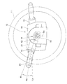
- FIG. 2 is an overall view of a neutral state of the turn signal switch device shown in FIG. 1.
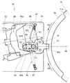
- FIG. 3 is an enlarged view of a cancel mechanism shown in FIG. 2.
- FIG. 4 is a perspective view of the cancel mechanism shown in FIG. 3. It is the figure which looked at the relationship between the cancellation pin shown in FIG. 4 and a return spring from the front end side of the cancellation pin. It is sectional drawing which showed the support structure of the 1st axis
- FIG. 5 is a cross-sectional view around a concave portion of the cancel pin shown in FIG. 4. It is the figure which showed the left turn state of the turn signal switch apparatus shown by FIG.
- FIG. 9 is an enlarged view showing the cancel mechanism shown in FIG. 8.
- a vehicle turn signal switch device including a cancel mechanism according to an embodiment will be described.
- a combination switch unit 13 is disposed in the vicinity of the steering shaft 12 connected to the steering wheel 11 of the vehicle.
- the combination switch unit 13 is provided on a steering column (not shown).
- a wiper switch device 15 is provided on the right side and a turn signal switch device 16 is provided on the left side with respect to the common base 14 located in the center. .
- the turn signal switch device 16 emits a right turn lighting switch signal when the operation lever 23 at the neutral position Ne is swung in the lifting direction and emits a left turn lighting signal when the swing operation is performed in the push-down direction.
- the right turn signal (not shown) blinks in response to the right turn lighting signal
- the left turn signal (not shown) blinks in response to the left turn lighting signal.
- the turn signal switch device 16 will be described in detail.
- the turn signal switch device 16 operates a fixed member 21 attached to the common base 14, a movable plate 22 supported by the fixed member 21 so as to be swingable, and the movable plate 22.
- An operation lever 23 and left and right switches 24L and 24R operated by the movable board 22 are included.
- the fixing member 21 includes a case 31 whose top is opened and a detachable lid 32 for closing the upper opening of the case 31.
- the movable platen 22 is supported by a case 31 and a lid 32 so as to be swingable.
- the operation lever 23 is attached to the movable platen 22.
- a straight line Ne passing through the center Sc of the steering shaft 12 and the swing center Mc of the movable platen 22 is hereinafter referred to as a reference line Ne.
- the reference line Ne is appropriately referred to as a “neutral position Ne”.
- Such a turn signal switch device 16 includes a cancel mechanism 40.
- the cancel mechanism 40 includes a cancel cam 41, a cancel pin 42, a guide groove 43, a cam groove 44, a return spring 45, and a cancel plate 46 as main components.
- the cancel cam 41 is a member that can rotate as the steering shaft 12 (FIG. 1) rotates. More specifically, the cancel cam 41 is an annular member that is fitted to the steering shaft 12 with its relative rotation being restricted, and a plurality of cam peaks 41a protrude from the outer peripheral surface.
- the fixing member 21 is located in the vicinity of the cancel cam 41.
- the cancel pin 42 is an elongated member along the reference line Ne, and can swing between the fixed member 21 (particularly, the lid 32 shown in FIG. 4) and the movable platen 22. In addition, it is supported so as to be able to advance and retreat toward the cancel cam 41.
- the cancel pin 42 is slidably contacted with the fixed member 21 (particularly the lid 32), and extends from the slidable contact surface 51 toward the fixed member 21 to be fixed.
- the first shaft 52 supported by the guide groove 43 of the member 21 and the anti-sliding contact surface 53 opposite to the sliding contact surface 51 extend toward the movable platen 22 and are supported by the cam groove 44 of the movable platen 22.
- a second shaft 54 The first shaft 52 and the second shaft 54 are located on the swing center line Cc of the cancel pin 42.
- the sliding contact surface 51 has one or a plurality of recesses 55 for storing grease.
- the guide groove 43 is a linearly elongated groove along the reference line Ne, and is formed in the fixing member 21 (particularly the lid 32).
- the guide groove 43 supports the first shaft 52 while guiding the first shaft 52 so that the cancel pin 42 can swing and can move forward and backward toward the cancel cam 41.
- the support length Lg (FIG. 6) at which the first shaft 52 is supported by the guide groove 43 is a length capable of maintaining the state in which the sliding contact surface 51 is in sliding contact with the lid 32 of the fixing member 21 as a whole. Is set.
- the guide groove 43 may be a long hole that penetrates the lid 32.
- the cam groove 44 is formed on the upper surface of the movable platen 22 so that the cancel pin 42 is displaced with respect to the cancel cam 41 when the movable platen 22 swings.
- the guide groove guides the second shaft 54. More specifically, the cam groove 44 has a guide convex portion 61 bulging from the groove bottom.
- the guide convex portion 61 is formed in a substantially isosceles triangular shape having a vertex 62 on the opposite side of the cancel cam 41 on the reference line Ne. And left and right oblique sides (right oblique side portion 63R and left oblique side portion 63L) inclined left and right from the vertex 62.
- the cancel pin 42 is slid by the single return spring 45 in the direction A1 toward the cancel cam 41 and the sliding contact surface 51 on the fixing member 21 (particularly the inner surface of the lid 32). It is urged
- the return spring 45 is constituted by a coil spring. Both end portions 45a and 45a of the coil spring 45 (return spring 45) are hooked on two latching portions 47 and 47 located on both sides with respect to the swing center line Cc of the cancel pin 42. The central portion 45 b of the coil spring 45 is hung on the spring hooking portion 56 of the cancel pin 42.
- the cancel pin 42 has a swing front end portion 57 that is directed to the cancel cam 41 with respect to the swing center line Cc, and a swing rear end portion 58 that extends to the opposite side of the swing front end portion 57.
- the spring hook 56 is formed by a lateral groove formed in the swing rear end 58.
- the lateral groove has a bottom surface on the swing tip portion 57 side and is open in the groove longitudinal direction (toward the two latching portions 47 and 47).
- the spring hooking portion 56 has a lid 32 of the fixing member 21 along the swing center line Cc of the cancel pin 42 with respect to the hooking positions of the two hooking portions 47, 47.
- the return spring 45 is positioned such that the central portion 45b is farther from the inner surface of the lid 32 than the both end portions 45a and 45a. For this reason, the cancel pin 42 is urged in the direction A ⁇ b> 2 slidably contacting the inner surface of the lid 32.
- the cancel plate 46 is located near the swing center Mc of the movable plate 22 with respect to the swing center line Cc of the cancel pin 42 and is provided on the movable plate 22. More specifically, the cancel plate 46 is formed in a substantially U shape with the cancel cam 41 side opened on the reference line Ne when viewed from the direction along the swing center line Cc of the cancel pin 42. The left and right arms 46a, 46a of the cancel plate 46 are located on the left and right side surfaces away from the swing rear end portion 58 of the cancel pin 42.
- the operation of the cancel mechanism 40 will be described.
- the second shaft 54 (FIG. 4) of the cancel pin 42 is located at the apex 62 of the guide convex portion 61. Yes.
- the swing tip portion 57 of the cancel pin 42 is located outside the rotation locus RL of the cancel cam 41.
- the movable platen 22 maintains the neutral position Ne by a click mechanism (not shown).
- the click mechanism is elastically engaged between the movable platen 22 and the case 31 and is released by a predetermined small load.
- the slidable contact surface 51 of the cancel pin 42 can slidably contact the lid 32 of the fixing member 21.
- the cancel pin 42 is urged by the return spring 45 in both the direction A1 toward the cancel cam 41 and the direction A2 in which the sliding contact surface 51 is in sliding contact with the lid 32.
- the slidable contact surface 51 receiving the urging force of the return spring 45 can always slidably contact the lid 32. For this reason, the frictional resistance when the cancel pin 42 is displaced is large as the sliding contact surface 51 is in sliding contact with the lid 32.
- the cancel pin 42 Since the frictional resistance between the lid 32 and the sliding contact surface 51 is large, the cancel pin 42 is displaced relatively slowly. Therefore, it is possible to suppress as much as possible the occurrence of a hitting sound caused by the cancel pin 42 hitting (hit) another part. Therefore, the comfort of the passenger compartment can be improved.
- the single return spring 45 can urge both the direction A1 toward the cancel cam 41 and the direction A2 in which the sliding contact surface 51 slides on the lid 32. For this reason, generation
- the cancel mechanism 40 returns the cancel wheel 42 to the neutral position Ne by the cancel cam 41 by returning the steering wheel 11 to the cancel direction R2 of the turn signal, and returns the movable plate 22 to the neutral position Ne. Is possible.
- the spring hooking portion 56 is fixed to the fixing member 21 along the swing center line Cc of the cancel pin 42 with respect to the hooking positions 47 a and 47 a of the two hooking portions 47 and 47. It is located away from the lid 32. For this reason, it is possible to easily set the urging force in the direction A2 in which the sliding contact surface 51 is in sliding contact with the inner surface of the lid 32. As a result, the frictional resistance between the inner surface of the lid 32 and the sliding contact surface 51 can be easily set. Can be set.
- the sliding contact surface 51 has a recess 55 for storing grease. For this reason, an oil film can be formed over a long period between the inner surface of the lid 32 and the sliding contact surface 51. Therefore, the frictional resistance between the inner surface of the lid 32 and the sliding contact surface 51 does not become excessive, and the sliding contact can be made smoothly.
- the support length Lg supported by the guide groove 43 on the first shaft 52 provided on the sliding contact surface 51 of the cancel pin 42 is a lid.
- the length is set such that the slidable contact surface 51 can be kept in slidable contact with the entire surface.
- the first shaft 52 is sufficiently supported by the guide groove 43, the first shaft 52 is restricted from being inclined in the groove width direction of the guide groove 43. As a result, it is possible to maintain a state in which the sliding contact surface 51 is in sliding contact with the inner surface of the lid 32 throughout. The frictional resistance between the inner surface of the lid 32 and the sliding contact surface 51 is appropriately maintained. Furthermore, since the sliding contact surface 51 has a recess 55 (FIG. 7) for storing grease, an oil film can be formed between the inner surface of the lid 32 and the sliding contact surface 51 over a long period of time. .
- the fixing member 21 is not limited to the combined structure of the case 31 and the lid 32, and can be constituted by a single member, for example.
- the sliding contact surface 51 of the cancel pin 42 is not limited to the configuration in sliding contact with the inner surface of the lid 32, and may be configured to be in sliding contact with the inner surface of the case 31, for example.
- the return spring 45 is not limited to a single one but may be a plurality. That is, the cancel pin 42 is provided by one or a plurality of return springs in both the direction A1 toward the cancel cam 41 and the direction A2 in which the sliding contact surface 51 is in sliding contact with the fixing member 21 (particularly the inner surface of the lid 32). Any configuration that is energized may be used.
- each of the two replacement members has a “spring hooking position” that is fixed to the fixing member 21 along the swing center line Cc of the cancel pin 42 with respect to the hooking positions 47 a and 47 a of the two hooking portions 47 and 47. It is located away from the lid 32.
- two cancel pins 42 are provided in both the direction A1 toward the cancel cam 41 and the direction A2 in which the sliding contact surface 51 is in sliding contact with the fixing member 21 (particularly the inner surface of the lid 32). It is energized by the “pulling spring”.
- the cancel mechanism 40 of the present invention is suitable for use in various vehicle turn signal switch devices.
Landscapes
- Engineering & Computer Science (AREA)
- Mechanical Engineering (AREA)
- Lighting Device Outwards From Vehicle And Optical Signal (AREA)
- Mechanisms For Operating Contacts (AREA)
- Switches With Compound Operations (AREA)
Priority Applications (6)
| Application Number | Priority Date | Filing Date | Title |
|---|---|---|---|
| JP2013533552A JP5617043B2 (ja) | 2011-09-13 | 2012-07-09 | 車両用ターンシグナルスイッチ装置 |
| EP12832484.5A EP2756991A4 (en) | 2011-09-13 | 2012-07-09 | BLINKER SWITCH DEVICE FOR VEHICLE |
| BR112014005982A BR112014005982A2 (pt) | 2011-09-13 | 2012-07-09 | dispositivo de comutação de sinal de seta de veículo |
| CN201280044378.0A CN103826924B (zh) | 2011-09-13 | 2012-07-09 | 车辆用转向信号开关装置 |
| US14/344,090 US9221391B2 (en) | 2011-09-13 | 2012-07-09 | Vehicle turn signal switch device |
| IN2694CHN2014 IN2014CN02694A (enExample) | 2011-09-13 | 2012-07-09 |
Applications Claiming Priority (2)
| Application Number | Priority Date | Filing Date | Title |
|---|---|---|---|
| JP2011-200022 | 2011-09-13 | ||
| JP2011200022 | 2011-09-13 |
Publications (1)
| Publication Number | Publication Date |
|---|---|
| WO2013038786A1 true WO2013038786A1 (ja) | 2013-03-21 |
Family
ID=47883028
Family Applications (1)
| Application Number | Title | Priority Date | Filing Date |
|---|---|---|---|
| PCT/JP2012/067447 Ceased WO2013038786A1 (ja) | 2011-09-13 | 2012-07-09 | 車両用ターンシグナルスイッチ装置 |
Country Status (7)
| Country | Link |
|---|---|
| US (1) | US9221391B2 (enExample) |
| EP (1) | EP2756991A4 (enExample) |
| JP (1) | JP5617043B2 (enExample) |
| CN (1) | CN103826924B (enExample) |
| BR (1) | BR112014005982A2 (enExample) |
| IN (1) | IN2014CN02694A (enExample) |
| WO (1) | WO2013038786A1 (enExample) |
Cited By (1)
| Publication number | Priority date | Publication date | Assignee | Title |
|---|---|---|---|---|
| WO2018079108A1 (ja) * | 2016-10-31 | 2018-05-03 | 株式会社東海理化電機製作所 | 方向指示機構 |
Families Citing this family (10)
| Publication number | Priority date | Publication date | Assignee | Title |
|---|---|---|---|---|
| CN104271935B (zh) | 2012-02-27 | 2017-05-03 | 何宜科技能源公司 | 用于升压内燃机的富氧等离子体发生器 |
| JP5965759B2 (ja) * | 2012-07-13 | 2016-08-10 | 矢崎総業株式会社 | 方向指示装置 |
| JP6581515B2 (ja) * | 2016-01-14 | 2019-09-25 | アルプスアルパイン株式会社 | 入力操作装置 |
| WO2017155895A1 (en) | 2016-03-07 | 2017-09-14 | HyTech Power, Inc. | A method of generating and distributing a second fuel for an internal combustion engine |
| US11352046B2 (en) | 2017-07-12 | 2022-06-07 | Ka Group Ag | Lever assembly for a steering column of a vehicle |
| DE102017120347A1 (de) | 2017-09-05 | 2019-03-07 | Valeo Schalter Und Sensoren Gmbh | Rückstellvorrichtung für einen Lenkstockhebel |
| US20190234348A1 (en) | 2018-01-29 | 2019-08-01 | Hytech Power, Llc | Ultra Low HHO Injection |
| DE102018119801B4 (de) * | 2018-08-15 | 2024-10-17 | Valeo Schalter Und Sensoren Gmbh | Rückstellvorrichtung für eine Fahrrichtungsanzeigevorrichtung eines Fahrzeugs, Fahrtrichtungsanzeigevorrichtung und Fahrzeug |
| JP7145106B2 (ja) * | 2019-03-07 | 2022-09-30 | 東洋電装株式会社 | ターンシグナルスイッチ装置のオートキャンセル機構 |
| JP7671745B2 (ja) * | 2019-10-25 | 2025-05-02 | ジーエイチエスピー・インコーポレイテッド | 軸方向に操作可能なトグルを有する方向指示器の自動解除機構 |
Citations (4)
| Publication number | Priority date | Publication date | Assignee | Title |
|---|---|---|---|---|
| JPH0541967U (ja) * | 1991-11-09 | 1993-06-08 | 株式会社東海理化電機製作所 | 車両用方向指示操作レバーの戻し装置 |
| JPH08167345A (ja) * | 1994-12-12 | 1996-06-25 | Matsushita Electric Ind Co Ltd | ターンシグナルスイッチのキャンセル装置 |
| JPH11219641A (ja) | 1998-01-30 | 1999-08-10 | Niles Parts Co Ltd | 車両用ターンシグナルスイッチの構造 |
| JP2011126407A (ja) * | 2009-12-17 | 2011-06-30 | Panasonic Corp | 旋回方向指示装置 |
Family Cites Families (8)
| Publication number | Priority date | Publication date | Assignee | Title |
|---|---|---|---|---|
| US11012A (en) * | 1854-06-06 | Rivet-clamp foe | ||
| FR2246171A5 (enExample) * | 1973-09-28 | 1975-04-25 | Jaeger | |
| JPH0740429Y2 (ja) * | 1989-11-07 | 1995-09-20 | ナイルス部品株式会社 | ターンシグナルスイッチのキャンセル機構 |
| JP2631047B2 (ja) | 1991-08-08 | 1997-07-16 | 芳明 早坂 | 袋詰めスープダシ |
| JP3854427B2 (ja) * | 1999-06-16 | 2006-12-06 | アルプス電気株式会社 | ターンシグナルスイッチ装置 |
| JP2002225625A (ja) * | 2001-01-29 | 2002-08-14 | Yazaki Corp | ターンシグナルスイッチ |
| JP2010143460A (ja) * | 2008-12-19 | 2010-07-01 | Tokai Rika Co Ltd | 車両用方向指示装置 |
| JP5521513B2 (ja) * | 2009-11-30 | 2014-06-18 | パナソニック株式会社 | 旋回方向指示装置 |
-
2012
- 2012-07-09 IN IN2694CHN2014 patent/IN2014CN02694A/en unknown
- 2012-07-09 JP JP2013533552A patent/JP5617043B2/ja not_active Expired - Fee Related
- 2012-07-09 WO PCT/JP2012/067447 patent/WO2013038786A1/ja not_active Ceased
- 2012-07-09 EP EP12832484.5A patent/EP2756991A4/en not_active Withdrawn
- 2012-07-09 CN CN201280044378.0A patent/CN103826924B/zh not_active Expired - Fee Related
- 2012-07-09 BR BR112014005982A patent/BR112014005982A2/pt not_active IP Right Cessation
- 2012-07-09 US US14/344,090 patent/US9221391B2/en not_active Expired - Fee Related
Patent Citations (4)
| Publication number | Priority date | Publication date | Assignee | Title |
|---|---|---|---|---|
| JPH0541967U (ja) * | 1991-11-09 | 1993-06-08 | 株式会社東海理化電機製作所 | 車両用方向指示操作レバーの戻し装置 |
| JPH08167345A (ja) * | 1994-12-12 | 1996-06-25 | Matsushita Electric Ind Co Ltd | ターンシグナルスイッチのキャンセル装置 |
| JPH11219641A (ja) | 1998-01-30 | 1999-08-10 | Niles Parts Co Ltd | 車両用ターンシグナルスイッチの構造 |
| JP2011126407A (ja) * | 2009-12-17 | 2011-06-30 | Panasonic Corp | 旋回方向指示装置 |
Non-Patent Citations (1)
| Title |
|---|
| See also references of EP2756991A4 |
Cited By (2)
| Publication number | Priority date | Publication date | Assignee | Title |
|---|---|---|---|---|
| WO2018079108A1 (ja) * | 2016-10-31 | 2018-05-03 | 株式会社東海理化電機製作所 | 方向指示機構 |
| US11014491B2 (en) | 2016-10-31 | 2021-05-25 | Kabushiki Kaisha Tokai Rika Denki Seisakusho | Direction indication mechanism |
Also Published As
| Publication number | Publication date |
|---|---|
| JPWO2013038786A1 (ja) | 2015-03-23 |
| BR112014005982A2 (pt) | 2017-04-04 |
| US9221391B2 (en) | 2015-12-29 |
| CN103826924A (zh) | 2014-05-28 |
| EP2756991A4 (en) | 2015-07-22 |
| JP5617043B2 (ja) | 2014-10-29 |
| IN2014CN02694A (enExample) | 2015-07-03 |
| EP2756991A1 (en) | 2014-07-23 |
| CN103826924B (zh) | 2016-02-24 |
| US20150137964A1 (en) | 2015-05-21 |
Similar Documents
| Publication | Publication Date | Title |
|---|---|---|
| JP5617043B2 (ja) | 車両用ターンシグナルスイッチ装置 | |
| JP5543836B2 (ja) | 車両用サンバイザ | |
| JP5557946B1 (ja) | ヘッドレスト構造及びヘッドレスト装置 | |
| JP6125223B2 (ja) | ロック部構造 | |
| WO2014073432A1 (ja) | 折りたたみ式テーブル | |
| JP2012073348A (ja) | 画像形成装置 | |
| JP5459167B2 (ja) | 車両用収納装置 | |
| JP2014094705A (ja) | コンソールボックス | |
| JP4724555B2 (ja) | ヘッドレスト | |
| JP2007055589A (ja) | ワイパ装置 | |
| JP2020145077A (ja) | ターンシグナルスイッチ装置のオートキャンセル機構 | |
| JP6376092B2 (ja) | 車両用ペダル装置 | |
| JP2001260972A (ja) | 操作レバー握り代調整機構 | |
| JP4440833B2 (ja) | 車両用方向指示装置 | |
| JP4397331B2 (ja) | 可動体の動作機構 | |
| JP2010030483A (ja) | グラブボックス | |
| JP6455251B2 (ja) | 自動変速装置におけるシフトロック機構 | |
| JP4418732B2 (ja) | カップホルダ | |
| JP2016007948A (ja) | シートレール装置 | |
| JP2012071761A (ja) | シフト装置 | |
| JP5544641B2 (ja) | 収容構造体装置 | |
| JP2017039437A (ja) | シートバックのロック機構 | |
| JP2007145135A (ja) | 自動車用収納箱 | |
| JP2015051740A (ja) | 折り畳み式自転車 | |
| JP2009190599A (ja) | 車両用収納装置のドアの開閉装置 |
Legal Events
| Date | Code | Title | Description |
|---|---|---|---|
| WWE | Wipo information: entry into national phase |
Ref document number: 201280044378.0 Country of ref document: CN |
|
| 121 | Ep: the epo has been informed by wipo that ep was designated in this application |
Ref document number: 12832484 Country of ref document: EP Kind code of ref document: A1 |
|
| ENP | Entry into the national phase |
Ref document number: 2013533552 Country of ref document: JP Kind code of ref document: A |
|
| WWE | Wipo information: entry into national phase |
Ref document number: 14344090 Country of ref document: US |
|
| REEP | Request for entry into the european phase |
Ref document number: 2012832484 Country of ref document: EP |
|
| NENP | Non-entry into the national phase |
Ref country code: DE |
|
| REG | Reference to national code |
Ref country code: BR Ref legal event code: B01A Ref document number: 112014005982 Country of ref document: BR |
|
| ENP | Entry into the national phase |
Ref document number: 112014005982 Country of ref document: BR Kind code of ref document: A2 Effective date: 20140313 |