WO2013011815A1 - 主軸装置 - Google Patents
主軸装置 Download PDFInfo
- Publication number
- WO2013011815A1 WO2013011815A1 PCT/JP2012/066482 JP2012066482W WO2013011815A1 WO 2013011815 A1 WO2013011815 A1 WO 2013011815A1 JP 2012066482 W JP2012066482 W JP 2012066482W WO 2013011815 A1 WO2013011815 A1 WO 2013011815A1
- Authority
- WO
- WIPO (PCT)
- Prior art keywords
- bearing
- sleeve
- fitted
- spindle device
- rotor
- Prior art date
Links
Images


Classifications
-
- B—PERFORMING OPERATIONS; TRANSPORTING
- B23—MACHINE TOOLS; METAL-WORKING NOT OTHERWISE PROVIDED FOR
- B23Q—DETAILS, COMPONENTS, OR ACCESSORIES FOR MACHINE TOOLS, e.g. ARRANGEMENTS FOR COPYING OR CONTROLLING; MACHINE TOOLS IN GENERAL CHARACTERISED BY THE CONSTRUCTION OF PARTICULAR DETAILS OR COMPONENTS; COMBINATIONS OR ASSOCIATIONS OF METAL-WORKING MACHINES, NOT DIRECTED TO A PARTICULAR RESULT
- B23Q1/00—Members which are comprised in the general build-up of a form of machine, particularly relatively large fixed members
- B23Q1/70—Stationary or movable members for carrying working-spindles for attachment of tools or work
-
- B—PERFORMING OPERATIONS; TRANSPORTING
- B23—MACHINE TOOLS; METAL-WORKING NOT OTHERWISE PROVIDED FOR
- B23Q—DETAILS, COMPONENTS, OR ACCESSORIES FOR MACHINE TOOLS, e.g. ARRANGEMENTS FOR COPYING OR CONTROLLING; MACHINE TOOLS IN GENERAL CHARACTERISED BY THE CONSTRUCTION OF PARTICULAR DETAILS OR COMPONENTS; COMBINATIONS OR ASSOCIATIONS OF METAL-WORKING MACHINES, NOT DIRECTED TO A PARTICULAR RESULT
- B23Q11/00—Accessories fitted to machine tools for keeping tools or parts of the machine in good working condition or for cooling work; Safety devices specially combined with or arranged in, or specially adapted for use in connection with, machine tools
- B23Q11/12—Arrangements for cooling or lubricating parts of the machine
- B23Q11/126—Arrangements for cooling or lubricating parts of the machine for cooling only
- B23Q11/127—Arrangements for cooling or lubricating parts of the machine for cooling only for cooling motors or spindles
Definitions
- the present invention relates to a spindle device, and more particularly to a spindle device that can be applied to a spindle head such as a portal machining center, a multi-axis control machine tool, and the like and has a dmn of 1 million or more.
- the spindle of the spindle device applied to machine tools etc. receives a machining load while rotating at high speed, it is necessary to maintain rigidity against the machining load or deformation suppression characteristics against centrifugal force during high-speed rotation.
- metal is mainly used.
- the rotating shaft is used by exchanging tools, it needs to have wear resistance and hardness. For this reason, depending on the physical properties of the metal, there are limits to eigenvalues and thermal expansion, and the rotational speed and acceleration / deceleration time are also limited.
- a horizontal boring machine using a fiber-reinforced composite material as a rotating shaft is described.
- a rotating shaft that moves in the axial direction within the sleeve while rotating is disclosed, and a fiber-reinforced composite material is used to reduce weight and reduce thermal expansion, and as a rotating shaft.
- a metal or ceramic is provided at a necessary portion of the rotating shaft.
- the rotary shaft is rotatably supported by an air bearing, and a fiber layer is formed on the outer peripheral surface of the rotary shaft to suppress expansion of the rotary shaft and improve rigidity. It is described. Further, in the spindle device described in Patent Document 3, a groove is formed on both sides of the outer peripheral surface to which the rolling bearing of the rotating shaft is attached, and a carbon fiber layer is formed in the groove, thereby suppressing expansion due to centrifugal force. It is described.
- the taper portion, the flange portion, and the tool holding portion are integrally formed, and the collet attached to the tool is inserted into the tapered hole formed in the tool holding portion to hold the tool.
- a tool is fixed by tightening a nut screwed to a screw formed on the outer periphery of the part, and a carbon fiber layer is wound around the outer peripheral surface of the nut to prevent deformation of the nut.
- the tool holder described in Patent Document 5 also discloses a tool holder in which a carbon fiber layer is wound around the outer peripheral surface of the nut to suppress the expansion of the nut by centrifugal force.
- a multi-tasking machine tool that performs machining such as cutting and drilling by three-dimensional relative movement between a large workpiece and a tool
- a spindle having a tool while reciprocating a table to which the workpiece is attached
- a portal machining center that controls the X axis, the Y axis, and the Z axis is used.
- a saddle In a portal machining center, a saddle is attached to a cross rail supported by two columns, a spindle head is attached to the end of a ram that moves vertically with respect to the saddle, and two spindle heads are supported.
- the spindle device is pivotally attached to the arm via a bracket.
- a hollow cylindrical structure made of a fiber reinforced composite material in which carbon fibers or aramid fibers are wound at two kinds of brazing angles, and a hollow cylindrical structure
- a main shaft including a main shaft end member having a tapered surface to be inserted is disclosed (see, for example, Patent Document 6).
- an invar alloy having a lower thermal expansion than metal or ceramics is interposed between the hollow cylindrical structure and the hollow cylindrical member, thereby reducing the weight and reducing the thermal expansion in the axial direction of the main shaft.
- the improvement of processing accuracy is aimed at.
- the front side of the main shaft is supported by a fixed side bearing
- the rear side of the main shaft is supported by a free side bearing
- a bearing sleeve is fitted on the outer periphery of the free side bearing.
- the clearance between the housing and the outer housing is set to about several ⁇ m to several tens of ⁇ m in consideration of the thermal expansion of the main shaft during operation.
- the temperature of the spindle on the rotating side becomes higher than the temperature of the housing on the stationary side due to the heat of the motor and the heat of the bearing, and the spindle extends relatively in the axial direction.
- the difference is configured to escape to the rear side (or front side) of the main shaft by sliding of the bearing sleeve.
- the bearing sleeve, the rear lid, and the outer ring restraining member are made of a material such as invar or super invar, which has a smaller thermal expansion coefficient than steel, thereby reducing the change in the initial setting gap. It is described.
- Japanese Laid-Open Patent Publication No. 2-167602 Japanese Unexamined Patent Publication No. 7-51903 Japanese Patent Laid-Open No. 6-226506 (FIG. 3) Japanese Unexamined Patent Publication No. 6-218608 Japanese Unexamined Patent Publication No. 6-226516 Japanese Patent No. 2756155 Japanese Unexamined Patent Publication No. 2006-88245 Japanese Patent Laid-Open No. 1-295025
- the spindle for a machine tool is required to have high rotational accuracy and low vibration characteristics, it is incorporated in a state where a preload is applied, in which a clearance inside the bearing is eliminated during assembly.
- heat from the rotor is transmitted to the bearing inner ring through the metal rotating shaft, and therefore the inner ring temperature of the bearing tends to be higher than the outer ring temperature.
- the thermal expansion of the inner and outer rings differs due to the effect of the temperature difference between the inner and outer rings, and the internal load of the bearing increases in addition to the preload load.
- Patent Documents 3 to 5 a carbon fiber layer having a large longitudinal elastic modulus and a small specific gravity is formed on the outer peripheral side of the nut or main shaft, and the expansion of the nut or main shaft is suppressed by utilizing the mechanical strength of the carbon fiber layer.
- no consideration is given to suppressing the temperature rise of the inner ring and the elongation of the rotating shaft.
- it does not describe about the motor built-in type, and does not recognize the said subject.
- the main spindle of the machine tool disclosed in Patent Document 6 is intended to improve the processing accuracy by suppressing the thermal expansion in the axial direction of the main spindle due to thermal expansion, and a head ( The effect of heat transferred to the housing is not considered.
- an invar alloy with low thermal expansion is interposed on the inner surface side of the main shaft, there is a problem that the structure is complicated and difficult to manufacture.
- the bearing sleeve is made of a material having a smaller thermal expansion coefficient than steel such as Invar and Super Invar, and the change in the initial setting gap is reduced.
- These materials are known to have a low heat transfer coefficient.
- these materials have low damping properties against vibrations, and there is room for improvement, such as being fixed to a certain value depending on the material used.
- the PV value (P: contact surface pressure, V: sliding speed) of the rolling contact portion between the inner ring groove and ball and between the outer ring groove and ball increases, resulting in poor lubrication such as running out of the lubricating oil film. This may cause a seizure defect.
- Patent Document 8 uses a clearance fit between the shaft and the inner ring, and cannot be applied to a spindle device in which the shaft and the inner ring are fitted with zero or more interference.
- the present invention has been made in view of the above-described circumstances, and a first object is to provide a spindle device that can suppress a temperature increase of a rotating shaft and a bearing due to heat generation of a rotor and can improve machining accuracy. Is to provide.
- a second object of the present invention is to provide a spindle device that reduces the thermal deformation of the machine tool body and improves the machining accuracy by making it difficult for the heat of the spindle device to be transmitted to the machine tool body side. It is in.
- the third object of the present invention is to reduce the initial clearance of the sliding portion between the housing and the bearing sleeve, to reduce vibration at low speed, and to have high damping characteristics against vibration, even at high speed rotation.
- the main object is to provide a low-vibration spindle device.
- the fourth object of the present invention is to suppress the effects of thermal expansion and centrifugal force on the bearing on the rotating shaft that rotates at high speed, thereby preventing problems such as seizure due to increased preload of the bearing.
- An object of the present invention is to provide a spindle device that can perform the above operation.
- the above object of the present invention can be achieved by the following constitution.
- a spindle device comprising: The rotation axis is A first cylindrical member made of a metal material; A second cylindrical member which is disposed on the outer peripheral surface of the first cylindrical member, the rotor is fitted to the outer peripheral surface, and which is made of a material having a higher specific elastic modulus and a smaller linear expansion coefficient than the metal material of the first cylindrical member.
- a spindle device characterized by comprising: (2) The spindle device according to (1), wherein the rotor is fitted to the second cylindrical member with an interference. (3) The first cylindrical member includes a small-diameter portion where the second cylindrical member is disposed, and a large-diameter portion including a male screw portion to which a nut that regulates the axial position of the front bearing is tightened.
- the spindle apparatus according to (1) or (2) which is characterized.
- the second cylindrical member is disposed on the outer peripheral surface at a position spaced axially from the outer peripheral surface to which the rotor is fitted, and the inner ring of the front or rear bearing is fitted to the outer peripheral surface, and the metal material is used.
- the second cylindrical member has a stepped portion so that an outer peripheral surface on which the third cylindrical member is disposed has a small diameter
- the third cylindrical member is a thin sleeve fitted to an outer peripheral surface of the second cylindrical member.
- the third cylindrical member is a thin film member joined to the outer peripheral surface of the second cylindrical member by an electrical or chemical method.
- the third cylindrical member includes two third cylindrical members into which inner rings of the front bearing and the rear bearing are respectively fitted. Main spindle apparatus of description.
- a rotating shaft (11) a rotating shaft; Front and rear bearings that respectively support the rotary shaft rotatably with respect to the housing; A motor having a rotor arranged to rotate integrally with the rotary shaft between the front and rear bearings, and a stator arranged around the rotor; A spindle device comprising: A main shaft device, wherein a cylindrical member having a heat transfer coefficient smaller than that of the rotating shaft is disposed between the rotating shaft and the rotor. (12) The spindle device according to (11), wherein the cylindrical member is formed of a carbon fiber composite material.
- a rotating shaft (13) a rotating shaft; Front and rear bearings that respectively support the rotary shaft rotatably with respect to the housing; A motor having a rotor arranged to rotate integrally with the rotary shaft between the front and rear bearings, and a stator arranged around the rotor; A spindle device comprising: A rotor sleeve is provided between the rotor and the rotating shaft, A main shaft device characterized in that a member having a smaller heat transfer coefficient than the rotating shaft is partially interposed in one of the opposing surfaces of the rotor sleeve and the rotating shaft.
- annular inward convex portion is formed on the inner peripheral surface of the rotor sleeve so as to define a plurality of annular grooves, A member having a heat transfer coefficient smaller than that of the rotating shaft is disposed in the plurality of annular grooves,
- an annular outward convex portion is formed so as to define a plurality of annular grooves, A member having a heat transfer coefficient smaller than that of the rotating shaft is disposed in the plurality of annular grooves,
- a rotating shaft (F) a rotating shaft; Front and rear bearings that respectively support the rotary shaft rotatably with respect to the housing; A motor having a rotor arranged to rotate integrally with the rotary shaft between the front and rear bearings, and a stator arranged around the rotor; A spindle device comprising: At least one of the inner peripheral surface of the rotating shaft and the outer peripheral surface of the rotating shaft separated from the position where the rotor or the rotor sleeve to which the rotor is attached fits between the front and rear bearings.
- a spindle device characterized in that a member having a heat transfer coefficient smaller than that of the rotating shaft is arranged at a location.
- a spindle device comprising: The housing includes at least a metal inner sleeve fitted to the rear bearing and an outer sleeve made of a carbon fiber composite material fitted to the inner sleeve. (20) The inner sleeve is fitted on the front bearing and the rear bearing, The main shaft device according to (19), wherein the inner sleeve and the outer sleeve are fitted with a clearance fit.
- the housing further includes a front bearing housing in front of the inner sleeve and the outer sleeve in the axial direction,
- a seal member that seals the refrigerant supply path from the outside is disposed at both axial ends of a fitting portion between the inner sleeve and the outer sleeve. apparatus.
- (24) a rotating shaft;
- a fixed-side bearing in which an inner ring is fitted on one end side of the rotating shaft and an outer ring is fixed to the housing;
- a bearing sleeve disposed on the other end of the rotating shaft and fitted into the housing by a clearance fit;
- a free side bearing in which an inner ring is externally fitted to the other end side of the rotary shaft, an outer ring is fitted to the bearing sleeve, and the rotary shaft is rotatably supported in cooperation with the fixed side bearing;
- a spindle device having The main shaft device, wherein the bearing sleeve has at least an annular carbon fiber composite material having the same axial length as the bearing sleeve.
- the bearing sleeve includes an annular outer metal member having an outer peripheral surface that is disposed on an outer diameter side of the bearing sleeve and is fitted on the housing, and an inner peripheral surface that is disposed on the inner diameter side of the bearing sleeve and is fitted to the outer ring.
- the bearing sleeve is disposed on the outer diameter side thereof, and has an outer peripheral metal member having an outer peripheral surface that is fitted to the housing, and an inner member that is disposed on the inner side of the outer metal member and is fitted to the outer ring.
- the carbon fiber composite material having a peripheral surface.
- the bearing sleeve is disposed on the outer diameter side of the carbon fiber composite material having an outer peripheral surface that is fitted to the housing, and is disposed on the inner side of the carbon fiber composite material and is fitted to the outer ring.
- the fixed side bearing and the free side bearing are configured to be provided with a constant pressure preload, The spindle device according to any one of (24) to (27), wherein the bearing sleeve is provided with an outer ring retainer that comes into contact with one end surface of the outer ring of the free-side bearing.
- the fixed side bearing and the free side bearing are configured to be provided with a fixed position preload,
- the outer ring of the free side bearing and the bearing sleeve are fitted with a clearance fit, and the outer ring of the free side bearing is fixed to the bearing sleeve and a shoulder that protrudes radially inward from the bearing sleeve.
- the spindle device according to any one of (24) to (27), wherein the spindle device is positioned in an axial direction by an outer ring retainer.
- a rotating shaft (30) a rotating shaft; Front and rear bearings that respectively support the rotary shaft rotatably with respect to the housing; With A spindle device in which the rotating shaft and inner rings of the front and rear bearings are fitted with an interference of zero or more, A pair of inner ring spacers disposed opposite to both side surfaces of at least one inner ring of the front and rear bearings and externally fitted to the rotary shaft; The inner ring spacer has a hook-like protrusion that protrudes in the axial direction from the outer peripheral side and is fitted onto the shoulder of the outer peripheral surface of the inner ring, and has a smaller thermal expansion coefficient and a higher specific elastic modulus than the inner ring.
- a spindle device characterized by being formed from.
- the outer peripheral surface of the shoulder portion of the inner ring has an outer peripheral taper portion whose diameter gradually decreases toward the axial end portion
- the inner peripheral surface of the flange-shaped protrusion of the inner ring spacer has an inner peripheral taper portion whose diameter gradually increases toward the axial end
- the spindle device according to (30) wherein the outer peripheral taper portion of the inner ring and the inner peripheral taper portion of the flange-shaped protrusion of the inner ring spacer are fitted.
- the inner ring spacer has a main body part that is formed in an annular shape and is fitted on the rotation shaft, and the hook-shaped protrusion part that is formed separately from the main body part,
- the spindle apparatus according to (30) or (31), wherein the hook-shaped protrusion is fastened and fixed to the outer peripheral surface of the main body.
- the spindle device according to any one of (30) to (32), wherein the hook-shaped protrusion is formed of a plurality of protrusions that are separated in the circumferential direction.
- the spindle device according to any one of (30) to (34), wherein the inner ring spacer is formed of a carbon fiber composite material.
- the spindle device according to (35), wherein, in addition to the inner ring spacer, the rotating shaft is made of a carbon fiber composite material.
- the main spindle device includes a motor built-in in which a motor having a rotor fitted to the rotary shaft between the front and rear bearings and a stator arranged around the rotor is arranged.
- the spindle apparatus according to any one of (30) to (36), characterized by being a spindle apparatus of the type.
- the rotation shaft is disposed on the first cylindrical member made of a metal material and the outer peripheral surface of the first cylindrical member, the rotor is fitted to the outer peripheral surface, and the metal material of the first cylindrical member
- a second cylindrical member made of a material having a higher specific elastic modulus and a smaller linear expansion coefficient. Therefore, the second cylindrical member can suppress the temperature rise of the rotating shaft and the bearing due to the heat generated by the rotor, and the processing accuracy can be improved.
- a third cylinder made of a metal material is disposed on the outer peripheral surface at a position axially spaced from the outer peripheral surface to which the rotor of the second cylindrical member is fitted, and the inner ring of the front or rear bearing is fitted to the outer peripheral surface.
- a member thereby, the surface hardness of the third cylindrical member and the inner ring of the bearing can be made equal, the interference fit between them can be easily performed, and when the bearing is replaced, the mating surface Occurrence of defects such as scratches and scratches can be suppressed.
- the heat generated in the bearing from the fitting portion of the third cylindrical member and the inner circumferential surface of the bearing inner ring (the entire circumferential surface of the fitting portion becomes the heat transfer area) is passed through the inner ring spacer, One cylindrical member can be transmitted. That is, it is possible to suppress the occurrence of troubles such as seizure due to heat stagnating in the bearing inner ring and excessive preload due to the temperature difference between the bearing inner and outer rings.
- a cylindrical member having a smaller heat transfer coefficient than the rotating shaft is disposed between the rotating shaft and the rotor. This makes it difficult for the heat generated by the rotor to be transmitted to the inner ring of the front and rear bearings via the rotating shaft and further the rotating shaft, and the temperature difference between the inner and outer rings can be suppressed to maintain an appropriate preload. The occurrence of seizure of the bearing can be prevented. In addition, since the expansion of the rotating shaft itself is suppressed, good machining accuracy can be obtained.
- the member having a smaller heat transfer coefficient than the rotating shaft is partially interposed on either one of the opposed surfaces of the rotor sleeve and the rotating shaft, so that the rotor generates heat.
- the temperature difference between the inner and outer rings can be suppressed, and appropriate preload can be maintained, preventing the occurrence of seizure of the bearing can do.
- the opposing surfaces of the rotor sleeve and the rotating shaft other than the member having a low heat transfer coefficient can be fitted to each other, and appropriate management of the interference at the fitting portion is facilitated.
- the spindle device of the present invention between the front and rear bearings, the inner peripheral surface of the rotary shaft, and the outer peripheral surface of the rotary shaft away from the position where the rotor or the rotor sleeve is fitted. Since a member having a smaller heat transfer coefficient than the rotating shaft is arranged at least in one place, it is difficult for the heat transferred from the rotor to the rotating shaft to be transmitted to the inner ring of the front and rear bearings, resulting in a temperature difference between the inner and outer rings. Is suppressed, and an appropriate preload can be maintained, and the occurrence of seizure of the bearing can be prevented.
- the housing in which the front and rear bearings that rotatably support the rotating shaft are disposed includes at least a metal inner sleeve that fits around the rear bearing, and an inner sleeve. And an outer sleeve made of a carbon fiber composite material that fits outside, so that the heat from the rotating shaft is hardly transmitted to the machine side bracket by the action of the outer sleeve formed of a carbon fiber composite material having a low thermal conductivity. It is possible to perform high-accuracy processing by suppressing thermal deformation due to temperature rise on the machine side.
- the bearing sleeve fitted into the housing by clearance fitting has at least an annular carbon fiber composite material having the same axial length as the bearing sleeve.
- the carbon fiber composite material has anisotropy depending on the orientation direction of the carbon fiber, and the clearance setting can be selected by arbitrarily changing the coefficient of thermal expansion. Therefore, if a decrease in the clearance due to the difference between the temperature rise of the bearing sleeve and the temperature rise on the housing side can be assumed, the fiber orientation direction and angle should be selected according to this to obtain the optimum coefficient of thermal expansion. This is superior to conventional materials (such as Invar).
- the inner ring spacer is provided opposite to at least one side surface of the inner ring of the front and rear bearings that rotatably supports the rotating shaft and is fitted on the rotating shaft.
- the seat has a hook-like protrusion that protrudes in the axial direction from the outer peripheral side and is fitted onto the outer peripheral surface of the shoulder of the inner ring, and is made of a material having a higher specific elastic modulus and a smaller thermal expansion coefficient than the inner ring.
- the expansion of the inner ring spacer due to the centrifugal force during high-speed rotation is suppressed, the inner ring is restrained by the hook-shaped protrusion of the inner ring spacer that is fitted around the outer peripheral surface of the inner ring shoulder, and the inner ring is subjected to centrifugal force expansion. Can be suppressed. Furthermore, the amount of radial thermal expansion of the inner ring spacer that accompanies the temperature rise of the spindle device is smaller than the amount of radial thermal expansion of the inner ring, so the inner ring is pressed down by the difference in the amount of thermal expansion to further increase the thermal expansion of the inner ring. Can be pressed in small. As a result, an increase in the internal load of the bearing can be suppressed and occurrence of seizure or the like can be prevented.
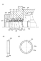
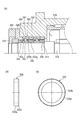
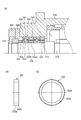
- (A) is sectional drawing which expands and shows the front side bearing vicinity of the main axis
- (b) is a side view of a front side inner ring spacer
- (c) is a front view of a front side inner ring spacer. It is.
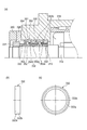
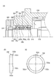
- (A) is sectional drawing which expands and shows the front side bearing vicinity of the main axis
- (b) is a side view of a front inner ring spacer
- (c) is a front view of a front inner ring spacer. It is.
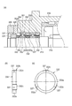
- (A) is sectional drawing which expands and shows the front side bearing vicinity of the main axis
- (b) is a side view of a front side inner ring spacer
- (c) is a front view of a front side inner ring spacer. It is.
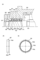
- (A) is sectional drawing which expands and shows the front side bearing vicinity of the main axis
- (b) is a side view of a front side inner ring spacer
- (c) is a front view of a front side inner ring spacer. It is.
- (A) is sectional drawing which expands and shows the front side bearing vicinity of the main axis
- (b) is a side view of a front side inner ring spacer
- (c) is a front view of a front side inner ring spacer. It is.
- (A) is sectional drawing which expands and shows the front side bearing vicinity of the main axis
- (b) is a side view of a front side inner ring spacer
- (c) is a front view of a front side inner ring spacer. It is.
- (A) is sectional drawing which expands and shows the front bearing vicinity of the main axis
- (b) is a side view of a front inner ring spacer
- (c) is a front view of a front inner ring spacer. It is.
- (A) is sectional drawing which expands and shows the front side bearing vicinity of the main axis
- (b) is a side view of a front side inner ring spacer
- (c) is a front view of a front side inner ring spacer. It is.
- FIG. 31 is a view for explaining a method of fastening the front inner ring spacer and the inner ring in the spindle device shown in FIG. 31, (a) is a view before tightening the nut, and (b) is a view after tightening the nut. .
- (A) is sectional drawing which expands and shows the front side bearing vicinity of the main axis
- (b) is a side view of a front side inner ring spacer
- (c) is a front view of a front side inner ring spacer. It is. It is sectional drawing which expands and shows the rear side bearing vicinity of the main axis
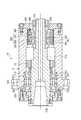
- the spindle device 10 is a motor built-in system, and a hollow rotary shaft 12 is provided at the axial center, and a draw bar 13 slides on the axis of the rotary shaft 12. It is freely inserted.
- the draw bar 13 urges the collet portion 15 that fixes the tool holder 14 in the counter-tool side direction (right direction in the figure) by the force of the disc spring 17, and the tool holder 14 has a tapered surface 18 of the rotary shaft 12. Mates with.
- a tool (not shown) is attached to the tool holder 14, and as a result, the rotary shaft 12 clamps the tool at one end (left side in the figure) so that the tool can be attached.
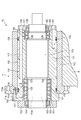
- the rotary shaft 12 is rotatably supported by the housing H by two rows of front bearings 50 and 50 that support the tool side and two rows of rear bearings 60 and 60 that support the opposite tool side.
- the housing H includes a front cover 40, a front bearing outer ring retainer 29, an outer cylinder 19, a rear housing 24, and a rear lid 26 in order from the tool side.
- the rotor 20 is fitted on the outer peripheral surface of the rotary shaft 12 between the front bearings 50 and 50 and the rear bearings 60 and 60 by shrink fitting.
- the stator 22 arranged around the rotor 20 is fixed to the outer cylinder 19 by fitting a cooling jacket 23 shrink-fitted to the stator 22 into the outer cylinder 19 constituting the housing H. Therefore, the rotor 20 and the stator 22 constitute a motor M, and by supplying electric power to the stator 22, a rotational force is generated in the rotor 20 and the rotating shaft 12 is rotated.
- Each front bearing 50 is an angular ball bearing having an outer ring 51, an inner ring 52, a ball 53 as a rolling element arranged with a contact angle, and a cage (not shown).
- the front bearings 50 and 50 (parallel combination) and the rear bearings 60 and 60 (parallel combination) are arranged to cooperate with each other to form a back combination.
- the outer rings 51, 51 of the front bearings 50, 50 are fitted into the outer cylinder 19, and are pivoted with respect to the outer cylinder 19 via the outer ring spacer 30 by the front bearing outer ring retainer 29 bolted to the outer cylinder 19. Positioned and fixed in the direction. Further, the inner rings 52, 52 of the front bearings 50, 50 are externally fitted to the rotating shaft 12, and are axially connected to the rotating shaft 12 via the inner ring spacer 32 by a nut 31 fastened to the rotating shaft 12. Positioning is fixed.
- the outer rings 61, 61 of the rear bearings 60, 60 are fitted inside a bearing sleeve 25 that is slidable in the axial direction with respect to the rear housing 24 inside the rear housing 24. It is positioned and fixed in the axial direction with respect to the bearing sleeve 25 via the outer ring spacer 34 by a rear bearing outer ring retainer 33 that is bolted to 25.
- a coil spring 38 for biasing the rear bearing outer ring retainer 33 toward the rear end is interposed between the rear housing 24 and the rear bearing outer ring retainer 33.
- the rear bearing outer ring retainer 33 and the bearing sleeve are interposed therebetween.
- outer rings 61 and 61, and the outer ring spacer 34 are integrally moved to the rear end side, the outer rings 61 and 61 are pressed in the axial direction, and a constant pressure preload corresponding to the urging force of the coil spring 38 is applied. It has come to be.
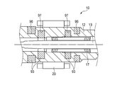
- Inner rings 62, 62 of the rear bearings 60, 60 are fitted on the rotary shaft 12, and are inserted into the inner ring spacer 36 and the detected portion 37 of the speed sensor by another nut 35 fastened to the rotary shaft 12. The positioning is fixed.
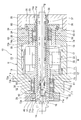
- the rotating shaft 12 is disposed on a first cylindrical member 71 made of a metal material such as high-tensile steel or carbon steel, and an outer peripheral surface of the first cylindrical member 71, and the rotor 20 is fitted on the outer peripheral surface.
- the inner rings 52, 52 of the front bearings 50, 50, the rotor 20, and the inner rings 62, 62 of the rear bearing 60 are fitted on the outer peripheral surface of the second cylindrical member 72. Further, the collet portion 15, the draw bar 13, and the disc spring 17 that move in the axial direction are accommodated inside the first cylindrical member 71.
- the first cylindrical member 71 is formed longer than the second cylindrical member 72 and regulates the axial positions of the small diameter portion 71a where the second cylindrical member 72 is disposed and the inner rings 52, 52 of the front bearings 50, 50.
- a large-diameter portion 71c having a male screw portion 71b to which the nut 31 is fastened.
- 71d is formed.
- a plurality of sliding contact surfaces 71e, 71f, 71g for slidably guiding the collet portion 15, the draw bar 13, and the disc spring 17 are formed on the inner peripheral surface of the first cylindrical member 71, and the tool side inner peripheral surface is formed. Is formed with a tapered surface 18 to which the tool holder 14 is attached.
- the carbon fiber composite material constituting the second cylindrical member 72 a material having a specific modulus greater than that of the metal material constituting the first cylindrical member 71, a smaller specific gravity, and a smaller thermal expansion coefficient (linear expansion coefficient) is used.
- the specific elastic modulus of the carbon fiber composite material is preferably at least twice, more preferably at least three times that of the metal material used in order to suppress expansion due to the centrifugal force of the rotating shaft 12 to an appropriate value.
- the carbon fiber composite material is anisotropic depending on the fiber direction, but the fiber direction is determined during molding in accordance with the direction of the load. Moreover, you may make it isotropic by making a fiber direction cross. Further, the fiber direction may be determined so that the specific elastic modulus in the circumferential direction is increased.
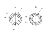
- first cylindrical member 71 and the second cylindrical member 72 As a method of joining the first cylindrical member 71 and the second cylindrical member 72, separately formed members may be joined by an interference fit or adhesion, or may be integrally formed. Furthermore, as shown in FIG. 2, in order to transmit sufficient rotational torque, a key 80 may be inserted between the first cylindrical member 71 and the second cylindrical member 72, or spline fitting may be performed.
- the carbon fiber composite material constituting the second cylindrical member 72 located on the radially outer side has a higher specific modulus, lower specific gravity, and heat than the metal material constituting the first cylindrical member 71 located on the inner side. Since the expansion coefficient is small, there is no gap in the fitting portion between them due to centrifugal force action and temperature change, and problems such as increased vibration during rotation and reduced rigidity do not occur.
- the carbon fiber composite material constituting the second cylindrical member 72 is a fabric in which yarns made of carbon fibers made of PAN (polyacrylonitrile) as a main raw material are arranged in parallel, or a fabric made of yarns made of carbon fibers.
- the sheet is manufactured by laminating a number of layers of a sheet formed by impregnating a thermosetting resin such as an epoxy resin containing a curing agent, winding the sheet around a cored bar, etc., and curing the sheet by heating.
- the tensile strength is 2060 MPa
- the tensile elastic modulus is 137 GPa
- the specific gravity is 1.55 g / cc.
- the tensile strength is equivalent or higher, and the specific gravity is about 1/5.
- the coefficient of thermal expansion can be reduced to ⁇ 5 to + 5 ⁇ 10 ⁇ 6 (K ⁇ 1 ) by optimizing the fiber direction and angle, so that it is 1/2 to 1 compared with the conventional carbon steel. / 10 or so.
- the rotor 20 and the second cylindrical member 72 are fitted with an interference due to shrink fitting. If the interference at the mating part decreases due to centrifugal force, rotational slippage due to torsional torque will occur, and if it becomes a clearance, the vibration of the main shaft may increase or machining may be defective. There is.
- the interference is preliminarily set in consideration of reduction of interference due to centrifugal force. For example, considering the reduction of interference due to centrifugal force, the interference is equal to or larger than (the centrifugal expansion amount of the inner diameter of the rotor 20 minus the centrifugal expansion amount of the outer diameter of the second cylindrical member 72). Set to.
- the linear expansion coefficient of the carbon fiber composite material is set to be smaller than that of the rotor 20 depending on the winding angle at the time of molding, it is considered that the interference is reduced due to the temperature increase of the rotor 20 and a clearance is formed. For this reason, it is preferable that the interference is set to be equal to or larger than (the above-mentioned centrifugal expansion amount + a decrease in interference due to temperature rise).
- a metal sleeve (not shown) may be interposed between the second cylindrical member 72 of the rotor 20, or as described in Patent Document 1, the outer peripheral surface of the carbon fiber composite material Alternatively, metal plating or ceramic may be sprayed.
- a spline or key may be formed on at least a part of the rotor 20 and the second cylindrical member 72 to integrally mold the carbon fiber composite material.
- the rotor 20 is externally fitted to the second cylindrical member 72.
- the heat generated by the rotor 20 is difficult to be transmitted to the inner rings 52 and 62 of the front and rear bearings 50 and 60 via the rotating shaft 12, and the temperature difference between the inner and outer rings 51, 52, 61 and 62 is suppressed, and an appropriate preload is achieved. Maintained.
- the expansion of the rotating shaft 12 itself is suppressed, good machining accuracy can be obtained.
- the rotating shaft 12 is provided with the 1st cylindrical member 71 which consists of metal materials inside the 2nd cylindrical member 72, the taper surface 18 to which the sliding contact surface 72f of the draw bar 13 and the tool holder 14 are attached is a 1st cylinder. It is comprised by the member 71, and the abrasion resistance in a specific site
- the rotor 20 is fitted to the second cylindrical member 72 with a margin, it is possible to prevent a gap from occurring even if a centrifugal force or a temperature rise of the rotor 20 occurs, and the rotor 20 rotates. In addition, an increase in vibration of the rotating shaft 12 can be suppressed.
- the first cylindrical member 71 includes a small-diameter portion 71a in which the second cylindrical member 72 is disposed, and a large-diameter portion 71c having a male screw portion 71b to which the nut 31 that regulates the axial position of the front bearing 50 is tightened. Therefore, the nut 31 can be securely fastened to the male screw portion 71b. Further, since the heat generation of the inner rings 52, 52 of the front bearings 50, 50 is transmitted from the inner ring spacer 32 and the nut 31 to the metal member such as the tool holder 14 via the first cylindrical member 71, the inner rings 52, 52 are transmitted. Temperature rise can be suppressed.
- the distance between the front bearing 50 and the rear bearing 60 becomes long, and the natural frequency in the radial direction of the rotating shaft tends to be small.
- it may be used in all areas up to the maximum number of revolutions, depending on the workpiece and machining conditions, rather than being used at a specific number of revolutions.
- the frequency is higher than the frequency at the maximum rotation, there is a possibility that machining cannot be performed due to the resonance action or abnormal vibration of the rotating shaft 12 in the resonance region may occur.
- a carbon fiber composite material having a larger specific modulus than that of a metal material is used. Therefore, in the case of the same bearing span, the natural frequency of the rotating shaft system (particularly, the natural frequency in the radial direction) is increased.
- the maximum number of rotations of the spindle device can be increased, and the machining rotation area can be widened.
- the carbon fiber composite material is excellent in vibration damping properties compared to the metal material, the dynamic rigidity of the rotating shaft 12 can be improved, and as a result, chatter vibration is hardly generated in severe processing conditions and finishing processing.
- the surface roughness is improved, the quality and glossiness of the processed surface are improved, and the processing accuracy is stabilized.
- the machining time and deceleration time of the spindle device depend on the size of the rotary inertia J.
- the rotational inertia of the hollow cylinder is given by the following calculation formula and is in a relationship proportional to the fourth power of the diameter.
- J (D4-d4) ⁇ L ⁇ ⁇ ⁇ ⁇ / 32
- D is the outer diameter of the hollow cylinder
- d is the inner diameter of the hollow cylinder
- L is the axial length of the hollow cylinder
- ⁇ is the specific gravity.
- the weight of the rotating shaft 12 as a whole decreases, and the rotating shaft 12 moves away from the center of rotation. Since the carbon fiber composite material is applied to the second cylindrical member 72, the rotational inertia can be reduced, the machining time and the deceleration time of the spindle device can be greatly shortened, and the machining tool replacement time can be shortened, thereby achieving high efficiency machining. Is possible.
- the front bearings 50 and 50 and the rear bearings 60 and 60 are fitted on the second cylindrical member 72 so that the surface of the rotary shaft 12 is infiltrated and adhered by the coolant. Rust is generated due to corrosion, and the rust enters the inside of the bearing, resulting in poor lubrication and preventing the bearing from seizing.
- the metal material is present on the inner diameter side or both end sides, the outer diameter of the rotating shaft and the reference surface for inner diameter finish grinding are secured, and finish grinding can be performed with high accuracy.
- a reference surface is provided on the carbon fiber composite material, wear and deformation are likely to occur, and it is difficult to ensure the coaxiality and roundness required for the high-speed main shaft. If the coaxiality and roundness are poor, the unbalance is large, causing vibration during high-speed rotation and poor machining accuracy.
- the inner rings 52, 52 of the front bearings 50, 50 are fixedly fitted to the first cylindrical member 71 of the rotary shaft 12 with an interference.
- the sleeve 81 may be configured to be positioned and fixed in the axial direction with respect to the rotary shaft 12.
- the fixing sleeve 81 is incorporated into the first cylindrical member 71 by shrink fitting, and the fixing sleeve 81 is disassembled from the first cylindrical member 71 between the fixing sleeve 81 and the first cylindrical member 71. This is done by applying hydraulic pressure to the hydraulic chamber 83.
- the fixed sleeve 81 is configured to directly contact the inner ring 52 without using a spacer or the like, the axial length of the fixed sleeve 81 can be set long. Therefore, the axial length of the fitting portion between the fixed sleeve 81 and the first cylindrical member 71 is increased, and the contact area for heat conduction can be further increased.
- the heat generation of the inner ring 52 of the front bearing 50 can be more efficiently transmitted to the first cylindrical member 71 side via the fixed sleeve 81, so that the temperature of the inner ring 52 decreases and the inner ring 52 and the outer ring 51 The temperature difference can be reduced. Therefore, an increase in the preload during rotation of the front bearing 50 is reduced, and the PV values of the rolling contact portions of the inner ring 52 and the ball 53 and the outer ring 51 and the ball 53 can be suppressed, so that the front bearing 50 can be prevented from being seized. .
- the fixing sleeve 81 and the first cylindrical member 71 of the rotating shaft 12 are fitted to each other, the tilting of the fixing sleeve 81 with respect to the rotating shaft 12 is suppressed, and the inner ring 52 can be fixed uniformly. This makes it possible to improve the processing accuracy.
- the inner ring 52 is positioned and fixed in the axial direction by the nut 31 as in the above-described embodiment, the axial length of the nut 31 is ensured long, or the screw pitch is shortened (fine screw).
- specifications such as extremely small fitting gaps between the nut 31 and the first cylindrical member 71 and between the spacer 32 and the second cylindrical member 72 (for example, intermediate fitting) It is possible to increase the effective contact area of conduction and release the heat generated in the inner ring 52.
- the inner ring 52 can be fixed uniformly and processing accuracy can be ensured. It is.
- the front bearing 50 disposed on the tool side is a bearing that applies a cutting load, and a heat generation amount is increased by the load. Further, since the taper surface 18 for holding the tool holder 14 is provided on the tool side of the spindle device 10, a wall thickness is required to ensure the shaft rigidity and the natural frequency of the shaft system, and the front bearing 50 Tends to increase, and as a result, the dmn value of the front bearing 50 increases. Therefore, it is very effective to provide the fixed sleeve 81 as described above so as to efficiently release the heat generated by the front bearing 50.
- the rear bearing 60 disposed on the side opposite to the tool is not directly subjected to a cutting load as compared with the front bearing 50 and is smaller in size than the front bearing 50. Therefore, as in the above-described embodiment.
- a configuration in which the nut 35 is positioned in the axial direction may be used.
- the inner rings 62, 62 of the rear bearings 60, 60 have an interference with the first cylindrical member 71 without using the nut 35 as necessary, for example, when there is a margin for securing an axial space. Then, it may be configured to be positioned and fixed in the axial direction with respect to the rotating shaft 12 by a fixing sleeve fitted outside (not shown).
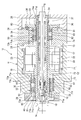
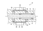
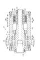
- the rotating shaft 12 includes a first cylindrical member 71 made of a metal material and a second cylindrical member 72 made of a carbon fiber composite material (CFRP), as in the first embodiment.
- the second cylindrical member 72 is disposed on the outer peripheral surface, and the inner rings 52, 52 of the front bearings 50, 50 and the inner rings 62, 62 of the rear bearings 60, 60 are fitted on the outer peripheral surface.
- three third cylindrical members 73 and 74 are fitted on the outer peripheral surface.
- the second cylindrical member 72 has an outer periphery in which the third cylindrical members 73 and 74 are disposed in the front portion and the rear portion that are positions spaced apart in the axial direction with respect to the axial intermediate portion in which the rotor 20 is fitted to the outer peripheral surface. Step portions 72a and 72b are provided so that the surface has a small diameter.
- the third cylindrical members 73 and 74 are fitted with the sleeve portions 73a and 74a on the outer peripheral surface having a small diameter in front of the stepped portion 72a and rearward of the stepped portion 72b, and the nuts of the sleeve portions 73a and 74a.
- Flange portions 73b, 74b extending radially outward from the side end portions are sandwiched between the axial side surfaces of the stepped portions 72a, 72b and the axial end surfaces of the inner rings 52, 62.
- the outer diameter of the flange portion 74b is set to be equal to or smaller than the outer diameter of the outer peripheral surface to which the rotor 20 is fitted so as not to interfere when the rotor 20 is fitted to the second cylindrical member 72.
- the third cylindrical members 73 and 74 are thin sleeves fitted to the outer peripheral surface of the second cylindrical member 72, and a metal material such as high-tensile steel or carbon steel whose surface hardness is equivalent to that of the first cylindrical member 71 is selected. It is preferred that The third cylindrical members 73 and 74 formed of such a thin sleeve are covered with the outer peripheral surface of the second cylindrical member 72 by shrink fitting, or by using a slight interference and bonding together. The outer peripheral surface of the member 72 is coupled.
- the inner rings 52, 52 of the front bearings 50, 50 and the inner rings 62, 62 of the rear bearings 60, 60 are fitted to the outer peripheral surfaces of the third cylindrical members 73, 74 with interference.
- the outer peripheral surface of the second cylindrical member 72 made of a carbon fiber composite material combined with the first cylindrical member 71 is subjected to a finishing process in order to ensure proper fitting with the third cylindrical members 73 and 74. Further, the outer peripheral surfaces of the third cylindrical members 73 and 74 made of a metal material are also subjected to a finishing process in order to ensure proper fitting with the inner rings 52 and 62.
- the carbon fiber composite material constituting the second cylindrical member 72 is superior to the metal material in terms of the specific elastic modulus, but the surface hardness tends to depend on the resin material as the base material and is relatively soft. Further, the fitting between the rotating shaft 12 and each of the inner rings 52 and 62 needs to be an interference fit with at least a clearance of 0 or more in order to increase the rigidity of the main shaft and improve the rotation accuracy of the shaft.
- the carbon fiber composite material (second cylindrical member 72) and the third cylindrical members 73 and 74 are coupled in a wide range in the axial direction.
- elastic deformation on the third cylindrical members 73 and 74 side can be expected. Can be reduced. Note that the contact surface pressure does not increase if both are bonded together as a small interference fit instead of a large interference fit.
- the fitting clearance between the third cylindrical members 73 and 74 and the inner rings 52 and 62 during operation is 0 to the interference side. It is desirable to set the fit when assembled.
- the inner rings of the bearings 50 and 60 are provided together with the nuts 31 and 35 and the inner ring spacers 32 and 36 on the opposite side.
- the axial fixing of the end can be an intermetal bond. Since the carbon fiber composite material uses a synthetic resin material as a base material, when the inner rings 52 and 62 and the carbon fiber composite material are tightly bonded with a certain load, the inner ring end portion and the contact portion of the carbon fiber composite material are between Elastic deformation tends to be large, and the tightening connection by the nuts 31 and 35 may be weakened.
- the third cylindrical members 73 and 74 with the flange portions 73b and 74b.
- the axial end surfaces of the inner rings 52 and 62 and the stepped portions 72a and 72b of the second cylindrical member 72 are not provided without providing the flange portions 73b and 74b. And may be directly joined. Further, the sleeve portions 73a and 74a and the flange portions 73b and 74b may be constituted by different members.
- the front and rear bearings 50 are provided on the outer peripheral surface of the second cylindrical member 72 on the outer peripheral surface at a position separated in the axial direction from the outer peripheral surface to which the rotor 20 is fitted.
- 60 are respectively fitted with the third cylindrical members 73, 74 made of a metal material, and the surface hardness of the third cylindrical members 73, 74 and the inner rings 52, 62 of the bearings 50, 60 is arranged.
- the amount of heat generated by the bearing is reduced by the inner ring spacer 32, from the fitting portion of the inner peripheral surface of the third cylindrical members 73, 74 and the bearing inner rings 52, 62 (the entire circumferential surface of the fitting portion becomes the heat transfer area). It can be transmitted to the front bearing nut 31 and the first cylindrical member 71 via 36. That is, it is possible to suppress the occurrence of problems such as seizure due to heat stagnating in the bearing inner rings 52 and 62 and excessive preload due to the temperature difference between the bearing inner and outer rings.
- the third cylindrical members 73 and 74 have flange portions 73b and 74b sandwiched between the axial side surfaces of the stepped portions 72a and 72b of the second cylindrical member 72 and the axial end surfaces of the inner rings 52 and 62. Even when the nuts 31 and 35 on the opposite side are strongly tightened, the inner ring ends of the bearings 50 and 60 can be fixed in the axial direction without causing damage such as cracking or chipping of the second cylindrical member 72.
- the third cylindrical members 73 and 74 are thin sleeves that fit on the outer peripheral surface of the second cylindrical member 72, but the third cylindrical members 73 and 74 are outer peripheral surfaces of the second cylindrical member 72. It may be a thin film member bonded to the surface by an electrical or chemical method. For example, when the following metal plating is used, a strong film can be formed.
- a base treatment layer for thermal spraying, a metal spray treatment layer, an intermediate plating layer, and an outermost plating layer By forming sequentially from the inside, a metal plating layer that is firmly bonded can be obtained.
- the base treatment layer has, for example, a thermal conductivity of 0.001 cal ⁇ cm ⁇ 1 ⁇ sec ⁇ 1 ⁇ deg ⁇ 1 or more, ⁇ ⁇ S ⁇ 0.05 ( ⁇ : thermal conductivity, S: m Carbon fiber composite material by blending a non-flat inorganic filler satisfying 2 / g) or a specially shaped metal or inorganic powder, such as an inorganic filler having complex irregularities on the surface, with a thermosetting resin It is formed by applying to the surface and thermosetting.
- the material of the metal spray-treated layer is not particularly limited as long as it can be electroplated on the surface, such as Cu, Ni, Al, and Fe.
- the material of the intermediate plating layer is selected from the viewpoint of sealing performance and corrosion resistance.
- Cu or Ni is particularly effective.
- the material of the outermost plating layer is appropriately selected depending on the application, but Ni and Cu are generally employed, and Cu plating is preferable when surface hardness is particularly required.
- Other configurations and operations are the same as those in the first embodiment.
- the inner rings 52, 52 of the front bearings 50, 50 are fixed sleeves that are fitted around the first cylindrical member 71 of the rotary shaft 12 with interference. 81 may be configured so as to be positioned and fixed in the axial direction with respect to the rotary shaft 12. In this case, the same effect as in FIG. 3 is obtained.
- the front bearings 50 and 50 and the rear bearings 60 and 60 are arranged so as to be a back combination. Even in such a spindle device, the same effects as those of the above-described embodiment can be obtained.
- the spindle device to which the present invention is applied is constituted by a pair of angular ball bearings so that a fixed position preload is applied to the front bearings 50, 50, and the rear bearing 60 is constituted by a single row cylindrical roller bearing. It may be something like that.
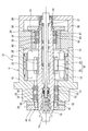
- the rotor 20 of the motor M is disposed so as to be integrally rotatable with the rotary shaft 12 via the rotor sleeve 70.
- the rotating shaft 12 is made of a metal material
- the rotor sleeve 70 is made of a carbon fiber composite material (CFRP).
- CFRP carbon fiber composite material
- CFRP a material having a thermal conductivity and a coefficient of thermal expansion smaller than that of the metal material, a specific elastic modulus higher than that of the metal material, and a specific gravity smaller than that of the metal material is used.
- the rotor 20 and the rotary shaft 12 have a strength equivalent to that of the metal. Can be insulated. As a result, the heat generated by the rotor 20 is not easily transmitted to the rotating shaft 12, and the thermal expansion of the rotating shaft 12 itself is suppressed, and good machining accuracy is maintained.
- the heat of the rotor 20 is difficult to be transmitted to the inner rings 52 and 62 of the front and rear bearings 50 and 60 via the rotating shaft 12, and the temperature increase of the inner ring temperature is suppressed, so that the inner and outer rings 51, 52, 61 and 62 are suppressed.
- the temperature difference can be reduced.
- problems such as bearing seizure due to an increase in internal load of the front and rear bearings 50 and 60 are prevented.
- the carbon fiber composite material for example, a woven fabric (sheet-like shape) made of PAN (polyacrylonitrile) as a main raw material, in which yarns made of carbon fibers are arranged in parallel, or made of yarns made of carbon fibers. ), A plurality of sheets impregnated with a thermosetting resin such as an epoxy resin containing a curing agent are superposed on each other, wound around a core metal, etc., and heated and cured.
- a thermosetting resin such as an epoxy resin containing a curing agent
- the tensile strength is 2060 MPa
- the tensile elastic modulus is 137 GPa
- the specific gravity is 1.55 g / cc.
- the tensile strength is equivalent or higher, and the specific gravity is about 1/5.
- the coefficient of thermal expansion can be reduced to ⁇ 5 to + 5 ⁇ 10 ⁇ 6 (K ⁇ 1 ) by optimizing the fiber direction and angle, so that it is 1/2 to 1 compared with the conventional carbon steel. / 10 or so.
- the heat of the outer rings 51 and 61 of the front and rear bearings 50 and 60 is radiated through the housing H to be fitted, whereas the heat of the inner rings 52 and 62 is hardly radiated, and the outer rings 51 and 61 are dissipated. It tends to be hotter. Therefore, the temperature management of the inner rings 52 and 62 is important for the internal load increase caused by the temperature difference between the inner and outer rings 51, 52, 61 and 62.
- the rotor 20 and the rotor sleeve 70, and the rotor sleeve 70 and the rotary shaft 12 are coupled by interference fit, adhesion, integral molding, or the like.
- a radial expansion during rotation due to a difference in radial expansion due to a difference in linear expansion coefficient of each member and a difference in expansion due to centrifugal force is provided.
- an appropriate margin should be provided so that at least no clearance is generated between the inner diameter of the rotating rotor 20 and the outer diameter of the rotor sleeve 70. It is preferable to select.
- the interference is equal to or larger than (the centrifugal expansion amount of the inner diameter of the rotor 20 ⁇ the centrifugal expansion amount of the outer diameter of the rotor sleeve 70).
- the linear expansion coefficient of the carbon fiber composite material is set smaller than that of the rotor 20 depending on the winding angle at the time of molding, it is considered that the interference is reduced due to the temperature rise of the rotor 20 and a clearance is generated. For this reason, it is preferable that the interference is set to be equal to or larger than (the above-mentioned centrifugal expansion amount + a decrease in interference due to temperature rise).
- the specific elastic modulus of the carbon fiber composite material is preferably at least twice, more preferably at least three times that of the metal material used in order to suppress expansion due to the centrifugal force of the rotating shaft 12 to an appropriate value. It is good.
- the carbon fiber composite material is anisotropic depending on the fiber direction, but the fiber direction is determined during molding in accordance with the direction of the load. Moreover, you may make it isotropic by making a fiber direction cross. Further, the fiber direction may be determined so that the specific elastic modulus in the circumferential direction is increased.
- the carbon fiber composite material has a thermal conductivity and a coefficient of thermal expansion smaller than that of the metal material, has a higher specific modulus than that of the metal material, and has a specific gravity smaller than that of the metal material. There is no gap in the fitting portion between the rotor sleeve 70 and the rotating shaft 12, and there is no problem that vibration during rotation increases or rigidity decreases.
- the heat conduction between the front bearing 50 and the rear bearing 60 that rotatably support the rotary shaft 12 is greater than that of the rotary shaft 12. Since the rotor 20 is externally fitted and fixed to the rotary shaft 12 via the rotor sleeve 70 formed of a carbon fiber composite material having a small rate, the heat generated by the rotor 20 is transmitted via the rotary shaft 12 and further via the rotary shaft 12.
- the temperature difference between the inner and outer rings 51, 52, 61, 62 can be suppressed, and an appropriate preload can be maintained, and the dmn value is 1 million. Even in the above high-speed rotation, it is possible to prevent the bearings 50 and 60 from being seized. Further, since the expansion of the rotary shaft 12 itself is also suppressed, good machining accuracy can be obtained.
- the rotor sleeve 70a disposed between the rotor 20 and the rotating shaft 12 is made of metal.
- An annular outward convex portion 92 is formed on the outer peripheral surface of the fitting portion of the rotating shaft 12 into which the rotor sleeve 70a is fitted so as to define a plurality of annular grooves 91.
- a carbon fiber composite material (CFRP) 93 is disposed in each annular groove 91 in a ring shape, and is integrally fixed to the rotating shaft 12 by tight fitting, bonding, or integral molding.
- the carbon fiber composite material As the carbon fiber composite material (CFRP), a material having a heat transfer coefficient and a coefficient of thermal expansion smaller than those of the metal material, a specific elastic modulus higher than that of the metal material, and a specific gravity smaller than that of the metal material is used.
- the carbon fiber composite material 93 having a small heat transfer coefficient is disposed in the plurality of annular grooves 91 fitted into the rotor sleeve 70a, and the contact area between the rotor sleeve 70a and the metal of the rotary shaft 12, that is, the heat conduction area.
- the heat of the rotor 20 is difficult to be transmitted to the inner rings 52 and 62 of the front and rear bearings 50 and 60 via the rotating shaft 12, and the temperature increase of the inner ring temperature is suppressed, so that the inner and outer rings 51, 52, 61 and 62 are suppressed.
- the temperature difference can be reduced. Thereby, troubles such as seizure of the bearing due to an increase in internal load of the front and rear bearings 50 and 60 can be prevented while having the same strength as that of the metal.
- the opposing surface of the rotor sleeve 70a and the rotating shaft 12 other than the position where the carbon fiber composite material 93 having a low heat transfer coefficient is located that is, the inner peripheral surface of the rotor sleeve 70a, and the annular outward convex portion of the rotating shaft 12 With 92, the fitting between metals is left.
- the metal rotor sleeve 70a is fitted only with the carbon fiber composite material 93 which has a lower surface hardness than the metal and is easily elastically deformed, it is difficult to properly manage the fit.
- the metal fitting between the annular outward convex portion 92 of the rotating shaft 12 and the rotor sleeve 70a it is easy to properly manage the interference in the fitting portion. Become.
- the carbon fiber composite material 93 for example, a woven fabric (sheet) formed by parallelly arranging yarns made of carbon fibers mainly made of PAN (polyacrylonitrile), or yarns made of carbon fibers.
- the sheet is manufactured by laminating a large number of sheets impregnated with a thermosetting resin such as an epoxy resin containing a curing agent, winding the sheet around a cored bar, etc., and heating and curing the sheet.
- the carbon fiber composite material 93 is anisotropic in the fiber direction, but the fiber direction can be determined in accordance with the load direction, and should be used isotropically by crossing the fiber directions during molding. .
- the tensile strength is 2060 MPa
- the tensile elastic modulus is 137 GPa
- the specific gravity is 1.55 g / cc.
- the coefficient of thermal expansion can be reduced to ⁇ 5 to + 5 ⁇ 10 ⁇ 6 (K ⁇ 1 ) by optimizing the fiber direction and angle, so that it is 1/2 to 1 compared with the conventional carbon steel. / 10 or so.
- the ratio between the annular groove 91 of the rotating shaft 12 and the annular outward projecting portion 92 in other words, the contact area between metals in the fitting portion between the rotor sleeve 70a and the rotating shaft 12, and the metal and carbon fiber composite.
- the ratio of the contact area with the material 93 is determined based on the balance between the heat insulating effect and the coupling strength in the fitting portion between the rotor sleeve 70a and the rotating shaft 12.
- the heat of the outer rings 51 and 61 of the front and rear bearings 50 and 60 is radiated through the housing H to be fitted, whereas the heat of the inner rings 52 and 62 is hardly radiated, and the outer rings 51 and 61 are dissipated. It tends to be hotter. Therefore, the temperature management of the inner rings 52 and 62 is important for the internal load increase caused by the temperature difference between the inner and outer rings 51, 52, 61 and 62.
- the metal rotor sleeve 70a and the rotor 20 are joined by tight fitting, bonding, or integral molding.
- the rotor 20 formed by laminating a plurality of silicon steel plates is fitted to the shaft portion in which the outward convex portion 92 made of metal and the carbon fiber composite material 93 are mixed by an interference fit
- the rotor 20 is fitted to the outward convex portion 92.
- the fit will vary between the silicon steel plate to be fitted and the silicon steel plate fitted with the carbon fiber composite material 93 having a surface hardness lower than that of the metal.
- the balance between the plurality of silicon steel plates may be shifted and affect the performance of the motor M.
- the rotor 20 is fitted to the rotary shaft 12 via the rotor sleeve 70a, so that the fit does not vary and the interference is easily managed.
- the rotor sleeve 70a is provided between the rotor 20 and the rotary shaft 12, and the outer peripheral surface of the rotary shaft 12 facing the rotor sleeve 70a. Since the carbon fiber composite material 93 which is a member having a smaller heat transfer coefficient than the rotating shaft 12 is partially interposed, the heat generation of the rotor 20 is caused by the front bearing 50 via the rotating shaft 12 and the rotating shaft 12.
- the temperature difference between the inner and outer rings 51, 52, 61, 62 can be suppressed, and an appropriate preload can be maintained, and seizure of the bearings 50, 60 occurs. Can be prevented. Further, since the expansion of the rotary shaft 12 itself is also suppressed, good machining accuracy can be obtained.
- annular outward convex portion 92 is formed on the outer peripheral surface of the rotating shaft 12 so as to define a plurality of annular grooves 91, and the carbon fiber composite having a smaller heat transfer coefficient than the rotating shaft 12 is formed in the plurality of annular grooves 91.
- the material 93 is disposed, and the inner peripheral surface of the rotor sleeve 70a and the annular outward convex portion 92 of the rotating shaft 12 are fitted with an interference fit.
- the rotation shaft 12 and the rotor sleeve 70a can be stably fitted to each other.
- the member having a heat transfer coefficient smaller than that of the rotating shaft 12 is formed from the carbon fiber composite material, heat transfer from the rotor 20 can be efficiently suppressed.
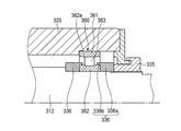
- FIG. 9 is a cross-sectional view of the main part of a spindle device according to a modification of the fourth embodiment.
- the arrangement position of the carbon fiber composite material 93 is opposite to that of the fourth embodiment, and a plurality of annular grooves 94 are defined on the inner peripheral surface of the metal rotor sleeve 70a.
- An annular inward convex portion 95 is formed.
- a carbon fiber composite material (CFRP) 93 is arranged in a ring shape in each annular groove 94, and is joined by tight fitting, adhesion, or integral molding.
- the carbon sleeve composite 93 having a small heat transfer coefficient is partially disposed on the inner peripheral surface of the rotor sleeve 70a to reduce the contact area between the rotor sleeve 70a and the rotating shaft 12, and thus the rotor sleeve.
- the heat transfer area from 70a to the rotating shaft 12 is reduced to suppress the heat of the rotor 20 transmitted to the rotating shaft 12 via the rotor sleeve 70a.
- the interference between the metal and the inward projection 95 of the rotor sleeve 70a and the outer peripheral surface of the rotary shaft 12 is left, and the rotary shaft 12 and the rotor sleeve 70a are fitted with an interference fit. Management becomes easy. Furthermore, by forming the carbon fiber composite material 93 as a separate member, the rotor sleeve 70a provided with the carbon fiber composite material 93 can be shared with other spindle devices.
- the rotor 20 is directly fitted and fixed to the approximate center of the rotating shaft 12 in the axial direction.
- a pair of outer circumferential annular grooves 96 are formed on the outer peripheral surface of the rotating shaft 12 that is separated from both sides in the axial direction from the position where the rotor 20 is fitted, and a pair of inner grooves are formed on the inner peripheral surface of the rotating shaft 12.
- a circumferential annular groove 97 is formed.
- a carbon fiber composite material (CFRP) 93 having a heat transfer coefficient smaller than that of the rotary shaft 12 is arranged in a ring shape in each of the outer peripheral side annular groove 96 and the inner peripheral side annular groove 97, and is tightly fitted, bonded, or integrally formed.
- the rotating shaft 12 is integrally coupled.
- the heat of the rotor 20 is hardly transmitted to the inner rings 52 and 62 of the front and rear bearings 50 and 60 via the rotating shaft 12, and the inner and outer rings 51, 52, 61, 62 are suppressed by suppressing the temperature rise of the inner ring.
- the temperature difference can be reduced.
- problems such as bearing seizure due to an increase in internal load of the front and rear bearings 50 and 60 can be prevented.
- the rotor 20 is fitted between the front and rear bearings 50 and 60 and the inner peripheral surface of the rotary shaft 12. Since the carbon fiber composite material 93 having a smaller heat transfer coefficient than the rotation shaft 12 is disposed on the outer peripheral surface of the rotation shaft 12 away from the position, the heat transmitted from the rotor 20 to the rotation shaft 12 is transferred to the front side and the rear side. It becomes difficult to transmit to the inner rings 52 and 62 of the bearings 50 and 60, the temperature difference between the inner and outer rings 51, 52, 61 and 62 can be suppressed, and an appropriate preload can be maintained, and seizure of the bearings 50 and 60 can be prevented. can do. Further, since the carbon fiber composite material 93 integrally bonded to both the annular grooves 96 and 97 has a strength equal to or higher than that of a metal, the strength of the rotating shaft 12 does not decrease.
- the rotor 20 can be externally fitted to the rotary shaft 12 via a rotor sleeve.
- the outer peripheral side annular groove 96 and the inner peripheral side annular groove 97 have substantially the same width and are formed at the same position in the axial direction, but are not limited to this. That is, the carbon fiber composite material 93 is formed between the front and rear bearings 50 and 60, and the outer peripheral surface of the rotary shaft 12 away from the position where the inner peripheral surface of the rotary shaft 12 and the rotor 20 or the rotor sleeve are fitted. What is necessary is just to arrange
- FIG. 11 is a cross-sectional view of a main part of a spindle device according to a modification of the fifth embodiment.
- the inner circumferential annular groove 97 of the rotary shaft 12 is disposed at a position overlapping the rotor 20 in the axial direction.
- the inner circumferential annular groove 97 is formed so as to overlap in the radial direction with the outer circumferential annular groove 96 formed on both axial sides of the rotor 20.
- a carbon fiber composite material 93 having a small heat transfer coefficient is integrally coupled to the rotary shaft 12 by tight fitting, bonding, or integral molding in the outer circumferential annular groove 96 and the inner circumferential annular groove 97. Therefore, the heat conduction area between the fitting portion of the rotating shaft 12 with the rotor 20 and the front bearing 50 and the rear bearing 60 is reduced, and the temperature of the inner rings 52 and 62 of the front and rear bearings 50 and 60 is increased. The temperature can be effectively suppressed.
- the fourth embodiment and the fifth embodiment can be applied in combination.
- the rotor sleeve 70a in which the carbon fiber composite material 93 is arranged in a ring shape in the annular groove 94 provided on the inner peripheral surface is provided on the rotating shaft 12. Is fitted to the outer peripheral surface.
- a carbon fiber composite material 93 is disposed on the inner circumferential side annular groove 97 formed on the rotary shaft 12 so as to overlap the fitting portion with the rotor sleeve 70a in the axial direction.
- the carbon fiber composite material 93 provided on the rotor sleeve 70a and the rotary shaft 12 allows the fitting portion between the rotor sleeve 70a and the rotary shaft 12, the front bearing 50, and the rear In the rotary shaft 12 between the side bearings 60, the heat conduction area is reduced, and the temperature rise of the inner rings 52, 62 of the front and rear bearings 50, 60 is suppressed.
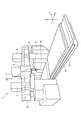
- FIG. 13 is a schematic perspective view of a portal machining center to which the spindle device of this embodiment is applied
- FIG. 14 is a cross-sectional view of the spindle device in FIG.
- a table 3 is supported on a bed 2 so as to be movable in the X-axis direction, and a pair of columns 4 are erected on both sides of the bed 2.
- a cross rail 5 is installed on the upper end of the column 4, and a saddle 6 is provided on the cross rail 5 so as to be movable in the Y-axis direction.
- the saddle 6 also supports a ram 7 that can be moved up and down in the Z-axis direction.
- the spindle device 10 of the present invention can be rotated and indexed around the Y axis and the Z axis.
- a spindle head 8 to be held is mounted.
- a tilt mechanism (not shown) is provided in the two support arms 8 a of the spindle head 8, and the spindle device 10 is rotationally indexed around the Y axis via the bracket 9 by this tilt mechanism.
- the spindle device 10 supports a housing H fitted in the bracket 9, a rotating shaft 113 inserted into the housing H, and the rotating shaft 113 rotatably with respect to the housing H.
- the rotating shaft 113 is formed in a hollow shape, and includes a draw bar extending in the axial direction, a collet provided on the leading end side of the draw bar, and between the draw bar and the rotating shaft 113, and the collet is A disc spring (both not shown) is drawn in to the tool side.
- the tool holder mounted on the collet is pulled into the opposite tool side (right side in FIG. 14), and is thus fitted to the taper surface 113a formed on the tool side inner peripheral surface of the rotary shaft 113. Is attached to the rotating shaft 113.
- the rotary shaft 113 is rotatable to the housing H by four rows of front bearings 150 that support the tool side (left side in FIG. 14) and two rows of rear bearings 160 that support the opposite tool side. It is supported.
- the housing H includes a metal inner sleeve 111 that fits around the plurality of front bearings 150 and the rear bearing 160, and an outer sleeve 112 made of a carbon fiber composite material that fits around the inner sleeve 111. Is fixedly fitted to the inner sleeve 111 by an interference fit or a combination of a clearance fit and an adhesive.
- the outer sleeve 112 is fixed to the bracket 9 of the spindle head 8 on the machine side by inserting a bolt (not shown) through a bolt hole 114 of a flange 112a provided at the front end in the axial direction.
- a cooling groove 116 that forms a coolant supply path 115 for circulating and supplying the coolant spirals on the outer peripheral surface of the inner sleeve 111 at the fitting portion between the inner sleeve 111 and the outer sleeve 112. Is formed. Both ends in the axial direction of the cooling groove 116 communicate with a supply hole 117 extending along the axial direction on the inner diameter side of the cooling groove 116, and the supply hole 117 is a rear bearing described later. It communicates with the refrigerant supply / discharge port 130 formed in the outer ring retainer 127.
- a refrigerant supply device (not shown) is connected to the refrigerant supply / discharge port 130 via a pipe, and a refrigerant such as cooling water is circulated and supplied to the refrigerant supply path 115 via the supply hole 117 to cool the inner sleeve 111. To do.
- O-ring grooves 118 are formed at both ends in the axial direction of the outer peripheral surface of the inner sleeve 111, and an O-ring 119 as a seal member is attached to the O-ring groove 118. Therefore, both sides in the axial direction of the refrigerant supply path 115 are sealed from the outside by the O-ring 119, and leakage of the refrigerant is prevented.
- Each front bearing 150 is an angular ball bearing having an outer ring 151, an inner ring 152, a ball 153 as a rolling element arranged with a contact angle, and a cage (not shown).
- the four rows of front bearings 150 are arranged such that two rows of front bearings 150 are combined in parallel from the front in the axial direction (left side in the figure) to form a pair, and each pair is a back combination. Further, the two rows of rear bearings 160 are arranged so as to form a back surface combination.
- each front bearing 150 is fitted in the inner sleeve 111 and is abutted against a stepped portion 120 formed on the inner sleeve 111 on the side opposite to the tool from the outer ring 51 and the front end of the inner sleeve 111 in the axial direction. It is positioned and fixed in the axial direction via an outer ring spacer 121 by a front bearing outer ring presser 122 fastened and fixed to the outer ring. Further, the inner ring 152 of each front bearing 150 is fitted on the rotating shaft 113, but is abutted against a step portion 123 formed on the rotating shaft 113 on the side opposite to the inner ring 152 and fastened to the rotating shaft 113. The nut 124 is positioned and fixed in the axial direction with respect to the rotary shaft 113 via the inner ring spacer 125.
- each rear bearing 160 is fitted into the inner sleeve 111, and between the outer ring 161 and the stepped portion 126 formed on the inner sleeve 111 on the tool side, and the rear end of the inner sleeve 111 in the axial direction.
- a gap in the axial direction is formed between the rear bearing outer ring presser 127 that is fastened and fixed to the outer ring.
- each rear bearing 160 is fitted on the rotary shaft 113, is abutted against a step portion 128 formed on the rotary shaft 113 on the tool side of the inner ring 162, and is fastened to the rotary shaft 113.
- the nut 129 is positioned and fixed.
- the spindle device 10 of the present embodiment configured as described above is fixed to the machine-side bracket 9 via an outer sleeve 112 made of a carbon fiber composite material having a thermal conductivity smaller than that of metal.
- heat generated on the spindle device 10 side is hardly transmitted to the bracket 9 on the machine side, thermal deformation on the machine side can be suppressed, and machining with high accuracy is possible.
- a motor built-in type main shaft device in which a driving motor is built in the main shaft device 10 since the heat generated by the rotor and the stator is difficult to be transmitted to the machine side, the effect of the present invention is great.
- the outer sleeve 112 having a relatively large volume is formed of a carbon fiber composite material having a small specific gravity, the mass of the spindle device 10 is reduced.
- the inertia of the feed shaft on which the spindle device 10 is mounted can be reduced, and the movement acceleration of the spindle device 10 can be increased. Therefore, the tool change time, the movement time of the spindle device 10 to the machining site, and the like can be shortened to increase the actual machining time, and the machining efficiency is improved.
- the inertia of the spindle apparatus 10 can be reduced, so that turning acceleration is improved and machining with high efficiency is possible.
- chatter may occur when machining difficult-to-cut materials such as titanium or when the sharpness of the blade is lowered.
- the carbon fiber composite material has good vibration damping characteristics, the spindle device 10 Side vibration is difficult to be transmitted to the bracket 9 on the machine side, and resonance phenomenon is prevented, so that high machining accuracy is maintained.
- the motor built-in spindle device 10 in which the drive motor is built in the spindle device 10 is effective because the heat generated by the motor can be suppressed from being transmitted to the machine side. Furthermore, since the specific gravity of the carbon fiber composite material is small, the mass and inertial force of the spindle device 10 can be reduced, and the spindle head can be moved at a higher speed, thereby improving the production efficiency.
- the refrigerant supply path 115 that circulates and supplies the refrigerant is disposed in the fitting portion between the inner sleeve 111 and the outer sleeve 112, so that the inner sleeve 111 can be effectively used by the refrigerant. Further, combined with the low thermal conductivity of the carbon fiber composite material, the temperature rise on the machine side is suppressed. As a result, thermal deformation due to temperature rise on the machine side can be suppressed, and processing with high accuracy becomes possible.
- the O-rings 119 that seal the refrigerant supply path 115 from the outside are disposed at both axial ends of the fitting portion between the inner sleeve 111 and the outer sleeve 112. The refrigerant leakage from the refrigerant supply path 115 can be reliably prevented.
- the spindle device 10 of the seventh embodiment has the same basic configuration as that of the spindle device 10 of the sixth embodiment, but the inner sleeve 111 and the outer sleeve 112 are fitted by a clearance fit, and the inner sleeve 111 has its axis. The difference is that the flange 111 a formed at the front end in the direction is fastened to the outer sleeve 112 by a bolt 131.
- the metallic inner sleeve 111 thermally expands in the radial direction.
- the outer sleeve 112 made of a carbon fiber composite material is less likely to expand than the inner sleeve 111, and as a result, the inner sleeve 111 is pressed from the outside and is fitted to the front and rear bearings 150 and 160 that fit inside the inner sleeve 111. May have an effect.
- the inner sleeve 111 and the outer sleeve 112 are fitted with a proper gap, so that the inner sleeve 111 can be prevented from being pressed by the outer sleeve 112, and the inner sleeve 111 can be prevented from being pressed.
- the fitting clearance between the sleeve 111 and the front and rear bearings 150 and 160 is reduced, and the influence on the internal load of the bearings 150 and 160 is reduced.
- Other functions and effects are the same as those of the spindle device 10 of the sixth embodiment.
- the housing H of the spindle device 10 of the present embodiment includes an inner sleeve 111, an outer sleeve 112, and a front bearing housing 135.
- the front bearing housing 135 is made of metal, is fixed to the axially forward end surface 112b of the inner sleeve 111, and is disposed axially forward of the inner sleeve 111 and the outer sleeve 112. In other words, the front bearing housing 135 is configured not to be fitted into the outer sleeve 112.
- the four rows of front bearings 150 are arranged to be fitted in the front bearing housing 135 and cooperate with the two rows of rear bearings 160 arranged on the side opposite to the inner sleeve 111 to rotate the rotary shaft 113.
- the outer ring 151 of each front bearing 150 is fitted in the front bearing housing 135, but is abutted against a stepped portion 136 formed on the front bearing housing 135 on the side opposite to the outer ring 151, and the front bearing housing 135. It is positioned and fixed in the axial direction via an outer ring spacer 121 by a front bearing outer ring retainer 122 fastened to the front end in the axial direction.
- each front bearing 150 is fitted on the rotating shaft 113, but is abutted against a step portion 137 formed on the rotating shaft 113 on the side opposite to the inner ring 152 and fastened to the rotating shaft 113.
- the nut 124 is positioned and fixed in the axial direction with respect to the rotary shaft 113 via the inner ring spacer 125.
- the metal sleeve 111 is made as the temperature of the spindle device 10 increases.
- the inner sleeve 111, the rotating shaft 113, the outer ring 151, the inner ring 152, etc. are thermally expanded in the radial direction, but the outer sleeve 112 made of carbon fiber composite material is difficult to expand, and therefore the outer sleeve 112 presses the inner sleeve 111 from the outside. And the outer ring 151 is contracted. As a result, the internal load of the front bearing 150 may increase.
- the front bearing 150 disposed on the tool side is a bearing that applies a cutting load, it is necessary to set the inner diameter larger than that of the rear bearing 160 in order to ensure rigidity. Further, since the taper surface 113a for holding the tool is provided on the tool side of the spindle device 10, a wall thickness is required to ensure the shaft rigidity and the natural frequency of the shaft system, and the inner diameter of the front bearing 150 is increased. Becomes larger. Therefore, the front bearing 150 tends to have a larger dmn value than the rear bearing 160.
- the spindle device 10 of the present embodiment since the outer sleeve 112 made of a carbon fiber composite material is not externally fitted to the front bearing housing 135 in which each front bearing 150 is fitted, the pressing action from the outside is achieved. In addition, even during high-speed rotation, an increase in the internal load of the front bearing 150 described above can be suppressed, and occurrence of problems such as seizure can be suppressed.
- the front bearing housing 135 is fixed to the inner sleeve 111 made of a metal material, and there is no fitting portion with the outer sleeve 112 made of a carbon fiber composite material, which makes it difficult to select an appropriate fit, so that the design is easy. .
- the housing H further includes the front bearing housing 135 in the axial direction front of the inner sleeve 111 and the outer sleeve 112, and the front bearing 150 includes the front bearing housing 135. Therefore, the thermal expansion of the front bearing housing 135 is not limited by the outer sleeve 112 made of a carbon fiber composite material, and adverse effects on the front bearing 150 fitted inside the front bearing housing 135 can be suppressed. .
- sixth to eighth embodiments can also be applied to a motor built-in type spindle apparatus in which a driving motor is built in the spindle apparatus.
- the spindle apparatus of 9th Embodiment is demonstrated with reference to FIG.
- the main spindle device 10 is a motor built-in system, and a hollow rotary shaft 212 is provided at the axial center, and a draw bar 213 slides on the axis of the rotary shaft 212. It is freely inserted.
- the draw bar 213 urges the collet portion 215 that fixes the tool holder 214 in the counter-tool side direction (right direction in the drawing) by the force of the disc spring 217, and the tool holder 214 has a tapered surface 218 of the rotating shaft 212. Mates with.
- a tool (not shown) is attached to the tool holder 214.
- the rotary shaft 212 clamps the tool at one end (the left side in the figure) so that the tool can be attached.
- the rotary shaft 212 includes two rows of front bearings (fixed side bearings) 250 and 250 that support the tool side, and two rows of rear bearings (free side bearings) 260 and 260 that support the opposite tool side.
- the housing H is rotatably supported.
- the housing H includes a front cover 240, a front bearing outer ring retainer 229, a front housing 227, an outer cylinder 219, a rear housing 224, and a rear lid 226 in order from the tool side.
- the rotor 220 is fitted on the outer peripheral surface of the rotary shaft 212 between the front bearings 250 and 250 and the rear bearings 260 and 260 by shrink fitting.
- the stator 222 disposed around the rotor 220 is fixed to the outer cylinder 219 by fitting the cooling jacket 223 shrink-fitted to the stator 222 into the outer cylinder 219 constituting the housing H. Therefore, the rotor 220 and the stator 222 constitute a motor M, and by supplying electric power to the stator 222, a rotational force is generated in the rotor 220 and the rotating shaft 212 is rotated.
- Each front bearing 250 is an angular ball bearing having an outer ring 251, an inner ring 252, a ball 253 as a rolling element arranged with a contact angle, and a retainer (not shown), and each rear bearing 260.
- the outer rings 251, 251 of the front bearings 250, 250 are fitted into the front housing 227, and are pivoted with respect to the front housing 227 via the outer ring spacer 230 by a front bearing outer ring retainer 229 that is bolted to the front housing 227. Positioned and fixed in the direction. Further, the inner rings 252 and 252 of the front bearings 250 and 250 are fitted on the rotating shaft 212 and are axially connected to the rotating shaft 212 via the inner ring spacer 232 by a nut 231 fastened to the rotating shaft 212. Positioning is fixed.
- the outer rings 261, 261 of the rear bearings 260, 260 are fitted inside a bearing sleeve 225 that is slidable in the axial direction with respect to the rear housing 224 inside the rear housing 224.
- the outer rings 261 and 261 are in contact with the rear bearing outer ring retainer 233 that is bolted to the bearing sleeve 225, and are positioned and fixed in the axial direction with respect to the bearing sleeve 225 via the outer ring spacer 234. Has been.
- Inner rings 262 and 262 of the rear bearings 260 and 260 are externally fitted to the rotary shaft 212, and the detected portion 238 of the inner ring spacer 36 and the speed sensor 237 is moved by another nut 235 fastened to the rotary shaft 212. The positioning is fixed through.
- the front bearings 250 and 250 (parallel combination) and the rear bearings 260 and 260 (parallel combination) are arranged so as to form a back combination in cooperation with each other, and the front bearings 250 and 250 and the rear bearing 260, A constant pressure preload is applied to 260.
- An urging member 239 such as a spring is disposed between the rear housing 224 and the rear bearing outer ring retainer 233, and the rear bearing outer ring retainer 233 and the bearing sleeve 225 are arranged with respect to the rear housing 224. It becomes slidable in the axial direction.
- the bearing sleeve 225 is disposed on the outer diameter side thereof, and is disposed on the inner diameter side of the annular outer metal member 271 having an outer peripheral surface that is fitted to the rear housing 224, and is fitted to the outer rings 261 and 261.
- the outer metal member 271, the inner metal member 272, and the carbon fiber composite material 273 each have the same axial length as the bearing sleeve 225, and the bearing sleeve 225 is configured in a radial multilayer structure.
- the carbon fiber composite material 273 has a higher specific elastic modulus, a lower specific gravity, and a lower thermal expansion coefficient than the metal materials constituting the outer and inner metal members 271,272.
- the specific elastic modulus of the carbon fiber composite material preferably corresponds to the thermal expansion of the outer and inner metal members 271 and 272 that together form the bearing sleeve 225, and is preferably more than twice that of the metal material used. Is more than 3 times.
- the carbon fiber composite material is anisotropic depending on the fiber direction, but the fiber direction is determined during molding in accordance with the direction of the load. Moreover, you may make it isotropic by making a fiber direction cross. Further, the fiber direction may be determined so that the specific elastic modulus in the circumferential direction is increased.
- the carbon fiber composite material 273 is hardened on a woven fabric (sheet-like) formed of carbon fibers made of PAN (polyacrylonitrile) as a main raw material, or made of carbon fibers. It is manufactured by laminating a number of sheets impregnated with a thermosetting resin such as an epoxy resin containing an agent, winding the sheet around a cored bar, etc., and curing it by heating.
- a thermosetting resin such as an epoxy resin containing an agent
- the tensile strength is 2060 MPa
- the tensile elastic modulus is 137 GPa
- the specific gravity is 1.55 g / cc.
- the coefficient of thermal expansion can be set to -5 to + 5 ° ⁇ 10 -6 ° C by optimizing the fiber direction and angle, so that it is about 1/2 to 1/10 that of conventional carbon steel. Can be.
- the fiber direction and angle are optimized so that an appropriate thermal expansion coefficient is obtained so that the clearance between the two is not reduced. May be used.
- separately formed members may be joined by interference fitting or adhesion, or may be integrally formed.
- the expansion of the inner metal member 272 can be suppressed by the outer carbon fiber composite material 273. Therefore, it is possible to prevent the outer diameter of the bearing sleeve 225 from expanding and the gap between the rear housing 224 and the bearing sleeve 225 from decreasing.
- the inner metal member 272 uses a low expansion cast member having a linear expansion coefficient closer to that of the carbon fiber composite material 273, such as novinite, to suppress a decrease in the gap between the rear housing 224 and the bearing sleeve 225. Although it is more preferable, for example, even when the material has the same linear expansion coefficient as that of the rear housing 224, the effect can be exerted by the pressing action of the carbon fiber composite material 273. In addition, it is preferable that the thickness of the carbon fiber composite material 273 is thicker than that of the inner metal member 272 because the pressing action is further increased.
- the present embodiment by combining the rear bearing outer ring holder 233 and the outer rings 261 and 261 that are not in direct contact with the rear housing 224 and have a large heat capacity, heat is released to the outer ring holder 233 side. is there. As a result, the initial clearance of the sliding portion between the rear housing 224 and the bearing sleeve 225 can be reduced, and vibration at low speed (low heat generation) can be reduced while maintaining slidability. Further, expansion of the outer diameter of the bearing sleeve can be suppressed by heat generation during high-speed rotation, reduction of the gap can be suppressed, and sliding failure of the bearing sleeve can be prevented. Furthermore, since the carbon fiber composite material is excellent in damping property against vibration, vibration can be suppressed.
- the bearing sleeve 225 has a combination of the outer metal member 271 and the carbon fiber composite material 273, or the carbon fiber composite material 273 and the inner metal member 272, as in the tenth and eleventh embodiments. Or a carbon fiber composite material 273 alone.
- the outer peripheral surface of the bearing sleeve 225 may be configured by the outer metal member 271 or the carbon fiber composite material 273 as long as it satisfies the slidability with the rear housing 224. . Further, metal plating or ceramic may be sprayed on the outer peripheral surface of the carbon fiber composite material.
- the rotating shaft 212 includes two rows of front bearings (fixed side bearings) 250 and 250 that support the tool side, and two rows of rear bearings (free side bearings) 260 that support the counter tool side.
- 260 is rotatably supported by the housing H and is driven to rotate by an external driving force.
- the housing H includes a front bearing outer ring retainer 229, an outer cylinder 219, and a rear lid 226 in order from the tool side.
- the front bearings 250 and 250 and the rear bearings 260 and 260 are arranged so as to be a combination of the back surfaces, respectively, so that a fixed position preload is applied.
- the outer rings 251 and 251 of the front bearings 250 and 250 are fitted into the outer cylinder 219, and are pivoted with respect to the outer cylinder 219 via the outer ring spacer 230 by the front bearing outer ring retainer 229 that is bolted to the outer cylinder 219. Positioned and fixed in the direction.
- the inner rings 252 and 252 of the front bearings 250 and 250 are fitted on the rotating shaft 212 and are axially connected to the rotating shaft 212 via the inner ring spacer 232 by a nut 231 fastened to the rotating shaft 212. Positioning is fixed.
- the outer rings 261 and 261 of the rear bearings 260 and 260 are fitted into a bearing sleeve 225 that is slidable in the axial direction with respect to the outer cylinder 219, and are positioned and fixed in the axial direction with respect to the bearing sleeve 225. Yes.
- Inner rings 262 and 262 of the rear bearings 260 and 260 are externally fitted to the rotary shaft 212, and are positioned and fixed in the axial direction via the inner ring spacer 236 by other nuts 235 fastened to the rotary shaft 212. Yes.
- the bearing sleeve 225 is disposed on the outer diameter side thereof, and is disposed on the inner side of the carbon fiber composite material (CFRP) 281 having the outer peripheral surface fitted to the outer cylinder 219 and the carbon fiber composite material 281, and the outer ring 261. , 261 and a ring-shaped inner metal member 282 having an inner peripheral surface to be fitted in the radial direction multilayer structure.
- CFRP carbon fiber composite material
- the carbon fiber composite material 281 and the inner metal member 282 are joined by adhesion or shrink fitting.
- the finishing of the outer peripheral surface of the carbon fiber composite material 281 is preferably performed after joining with the inner metal member 282.
- the bearing sleeve 225 is provided with a detent portion 285 to prevent a slip in the circumferential direction between the housing 219 and the bearing sleeve 225 due to an increase in the friction torque of the rolling bearing 260 during acceleration / deceleration.
- the outer side of the bearing sleeve 225 is the carbon fiber composite material 281 and the inner side is the inner metal member 282, whereby the expansion of the inner metal member 282 can be suppressed by the carbon fiber composite material 281. Reduction of the gap with the sleeve 225 can be suppressed.
- the carbon fiber composite material 281 is disposed outside the bearing sleeve 225 having a large diameter. By doing so, the expansion of the bearing sleeve 225 can be effectively suppressed.
- FIG. 19 is a cross-sectional view of the spindle device 10 according to the eleventh embodiment of the present embodiment.
- the fit between the inner peripheral surface of the bearing sleeve 225, that is, the inner peripheral surface of the inner metal member 282, and the outer peripheral surfaces of the outer rings 261 and 261 of the rear bearings 260 and 260 is a clearance fit.
- the clearance between the bearing sleeve 225 and the outer rings 261 and 261 is set to be larger than the radial expansion of the outer rings 261 and 261 due to the centrifugal force action of the balls 263 and 263 when the bearings 260 and 260 rotate at a high speed.
- the increase in internal preload due to centrifugal force can be mitigated by expansion of the outer ring.
- both end surfaces of the outer rings 261 and 261 are connected to the inner metal so that the outer rings 261 and 261 do not slide in the circumferential direction inside the bearing sleeve 225.
- the member 282 is configured to be pressed by a shoulder 282a and an outer ring presser 284 that is bolted to the inner metal member 282.
- vibrations of the bearings 260 and 260 that are a concern due to the clearance fit can be prevented.
- Other configurations and operations are the same as those in the tenth embodiment.
- FIG. 20 is a cross-sectional view of the spindle device 10 according to a first modification of the eleventh embodiment of the present embodiment.
- the configuration of the bearing sleeve 225 is different from that of the eleventh embodiment. That is, the bearing sleeve 225 is disposed on the outer diameter side thereof, and is disposed on the inner side of the outer metal member 283 and the annular outer metal member 283 having an outer peripheral surface that fits the outer cylinder 219, and the outer rings 261 and 261 have a clearance.
- a carbon fiber composite material (CFRP) 281 having an inner peripheral surface to be fitted by fitting.
- the clearance between the bearing sleeve 225 and the outer rings 261 and 261 is the same as that of the eleventh embodiment in that the radii of the outer rings 261 and 261 due to the centrifugal force action of the balls 263 and 263 when the bearings 260 and 260 rotate at a high speed. Since it is set to be larger than the directional expansion, the outer ring expansion that relaxes the increase in internal preload due to the centrifugal force is allowed by this clearance. Therefore, the inner peripheral surface of the bearing sleeve 225 may be made of the carbon fiber composite material 281 as in the modified example. Further, in this case, both end surfaces of the outer rings 261 and 261 are configured to be held by the shoulder portion 281a of the carbon fiber composite material 281 and the outer ring presser 284 bolted to the bearing sleeve 225.
- FIG. 21 is a cross-sectional view of the spindle device 10 according to a second modification of the eleventh embodiment of the present embodiment.
- the entire bearing sleeve 225 is composed of the carbon fiber composite material 281.
- the clearances between the bearing sleeve 225 and the outer rings 261 and 261 are the same as in the eleventh embodiment, and the outer rings 261 and 261 due to the centrifugal force action of the balls 263 and 263 when the bearings 260 and 260 rotate at a high speed. Since the clearance is set to be larger than the radial expansion of the outer ring, the outer ring expansion that relaxes the increase in internal preload due to the centrifugal force is allowed by this clearance.
- a spindle device according to a twelfth embodiment will be described with reference to FIG.
- a hollow rotating shaft 312 made of a metal material, more specifically, a chromium molybdenum steel material (SCM material) is provided at the center in the axial direction.
- a draw bar (not shown) is slidably inserted into the shaft core of the rotating shaft 312. The drawbars urge the collet that fixes the tool holder (not shown) in the counter tool side direction (right direction in the figure) by the force of the disc spring, and the tool holder fits with the tapered surface of the rotating shaft 312. Match.
- a tool is attached to the tool holder, and as a result, the rotary shaft 312 clamps the tool at one end (the left side in the figure) so that the tool can be attached.
- the rotary shaft 312 is rotatably supported on the housing H by two rows of front bearings 350 and 350 that support the tool side, and two rows of rear bearings 360 and 360 that support the opposite tool side.
- the housing H includes a front cover 340, a front bearing outer ring retainer 329, an outer cylinder 319, a rear housing 324, and a rear lid 326 in order from the tool side.
- the rotor 320 is fitted on the outer peripheral surface of the rotating shaft 312 between the front bearings 350 and 350 and the rear bearings 360 and 360 of the rotating shaft 312 by shrink fitting.
- the stator 322 disposed around the rotor 320 is fixed to the outer cylinder 319 by fitting the cooling jacket 323 shrink-fitted to the stator 322 into the outer cylinder 319 constituting the housing H. Therefore, the rotor 320 and the stator 322 constitute a motor M, and by supplying electric power to the stator 322, a rotational force is generated in the rotor 320 and the rotating shaft 312 is rotated.
- Each front bearing 350 is an angular ball bearing having an outer ring 351, an inner ring 352, a ball 353 as a rolling element arranged with a contact angle, and a cage 354, and each rear bearing 360 An angular ball bearing having an outer ring 361, an inner ring 362, a ball 363 as a rolling element, and a cage 364.
- the front bearings 350 and 350 (parallel combination) and the rear bearings 360 and 360 (parallel combination) are arranged so as to cooperate with each other to form a rear combination.
- the outer rings 351 and 351 of the front bearings 350 and 350 are fitted into the outer cylinder 319 and are fixed to the outer cylinder 319 via the front outer ring spacer 330 by a front bearing outer ring presser 329 that is bolted to the outer cylinder 319. It is positioned and fixed in the axial direction.
- Inner rings 352 and 352 of the front bearings 350 and 350 are externally fitted to the rotary shaft 312 with zero or more interference, and rotate with the step portion 313 of the rotary shaft 312 via the plurality of front inner ring spacers 332. It is sandwiched between a nut 331 fastened to the shaft 312 and positioned with respect to the rotating shaft 312.
- the outer rings 361 and 361 of the rear bearings 360 and 360 are fitted into a bearing sleeve 325 that is slidable in the axial direction inside the rear housing 324 and are bolted to the bearing sleeve 325. It is positioned and fixed in the axial direction with respect to the bearing sleeve 325 via the rear outer ring spacer 334 by the rear bearing outer ring presser 333. Further, the inner rings 362 and 362 of the rear bearings 360 and 360 are externally fitted to the rotating shaft 312 with zero or more interference, and the rear inner ring spacer 336 is secured by another nut 335 fastened to the rotating shaft 312. The positioning is fixed with respect to the rotary shaft 312 via
- front and rear inner ring spacers 332 and 336 and the inner rings 352 and 362 of the front and rear bearings 350 and 360 will be described in detail. Since the front inner ring spacer 332 and the front bearing 350, and the rear inner ring spacer 336 and the rear bearing 360 have the same configuration, in the following description, the front inner ring spacer 332 and the front bearing 350 are examples. It shall be explained in
- FIG. 23 (a) is an enlarged cross-sectional view showing the vicinity of the front bearing 350 of the spindle device 10, (b) is a side view of the front inner ring spacer 332, and (c) is a front view of the front inner ring spacer 332,
- Each inner ring 352 has a pair of front inner ring spacers 332 that are fitted on the rotary shaft 312 so as to face each other.
- the front inner ring spacer 332 is an annular main body 332a and a circle that protrudes in the axial direction from the outer peripheral side of the main body 332a and is fitted on the outer peripheral surface 352a of the shoulder of the inner ring 352, and is integrally formed with the main body 332a. And an annular hook-shaped protrusion 332b.
- the front inner ring spacer 332 is made of a material having a smaller coefficient of thermal expansion than that of the inner ring 352 and a larger specific elastic modulus, such as a carbon fiber composite material (CFRP).
- CFRP carbon fiber composite material
- the flange-shaped protrusion 332b of the front inner ring spacer 332 is fitted on the outer peripheral surface 352a of the shoulder of the inner ring 352 with zero or more interference when assembled, and the outer peripheral surface 352a of the shoulder of the inner ring 352 is It is pressed against the inner side in the radial direction by the hook-shaped protrusion 332b over the entire circumference.
- the flange-shaped protrusion 332b and the outer peripheral surface 352a of the shoulder portion of the inner ring 352 are fitted with an interference of zero or more when the temperature rises with the operation of the spindle device 10 and the thermal expansion of both.
- the maximum interference (diameter method) between the flange-like protrusion 332b of the front inner ring spacer 332 and the outer peripheral surface 352a of the shoulder of the inner ring 352 is the shape and meat of the front inner ring spacer 332 (hook-like protrusion 332b).
- the thickness is preferably 60 ⁇ m or less, more preferably 40 ⁇ m or less, and even more preferably 20 ⁇ m or less.
- the axial width of the fitting portion between the flange-shaped protrusion 332b and the outer peripheral surface 352a of the shoulder portion of the inner ring 352 is 10% of the axial width of the inner ring 352 in order to maintain the fitting state of both. The above is desirable.
- the outer diameter of the hook-shaped protrusion 332b is smaller than the inner diameter of the retainer 354, the hook-shaped protrusion 332b and the inner ring are prevented from interfering with the retainer 354.
- the axial width of the fitting portion with the outer peripheral surface 352a of the shoulder portion of 352 can be increased.
- the fitting of the front inner ring spacer 332 and the rotating shaft 312 and the fitting of the inner ring 352 and the rotating shaft 312 are performed with zero or more interference when assembled. It is good. As a result, the fitting state is maintained even when the temperature rises, and creep between the two is prevented, and the fitting state between the flange-like protrusion 332b and the outer peripheral surface 352a of the shoulder portion of the inner ring 352 is firmly maintained. can do.
- the front inner ring spacer 332 made of a carbon fiber composite material has a higher specific elastic modulus, a lower specific gravity, and a smaller coefficient of thermal expansion than the inner ring 352 made of metal, and therefore, centrifugal force expansion due to centrifugal force during operation. And the amount of thermal expansion due to temperature rise is reduced. Therefore, the outer peripheral surface 352a of the shoulder portion of the inner ring 352 is pressed by the hook-shaped protrusion 332b by the difference in expansion amount between the front inner ring spacer 332 and the inner ring 352, and the expansion of the inner ring 352 can be effectively suppressed. This also contributes to maintaining the fit between the rotating shaft 312 and the inner ring 352.
- the effect of restraining the inner ring 352 by the hook-shaped protrusion 332b is particularly effective in the spindle device 10 that rotates at a high speed such that dmn is 1 million or more.
- a carbon fiber composite material for example, a woven fabric (sheet-like) formed of yarns made of carbon fibers made of PAN (polyacrylonitrile) in parallel, or made of yarns made of carbon fibers. It is manufactured by laminating a plurality of sheets impregnated with a thermosetting resin such as an epoxy resin containing a curing agent, wrapping the sheet around a cored bar and the like, followed by heat curing.
- a thermosetting resin such as an epoxy resin containing a curing agent
- the tensile strength is 2060 MPa
- the tensile elastic modulus is 137 GPa
- the specific gravity is 1.55 g / cc.
- the tensile strength is equivalent or higher, and the specific gravity is about 1/5.
- the coefficient of thermal expansion can be reduced to ⁇ 5 to + 5 ⁇ 10 ⁇ 6 (K ⁇ 1 ) by optimizing the fiber direction and angle, so that it is 1/2 to 1 compared with the conventional carbon steel. / 10 or so.
- the front inner ring between the front inner rings that are disposed opposite to both side surfaces of the inner ring 352 of the front bearing 350 that rotatably supports the rotary shaft 312 and is fitted on the rotary shaft 312.
- a seat 332 is provided.
- the front inner ring spacer 332 has a hook-shaped protrusion 332b that protrudes in the axial direction from the outer peripheral side and is fitted on the outer peripheral surface 352a of the shoulder of the inner ring 352, has a higher specific elastic modulus than the inner ring 352, and has a thermal expansion coefficient. Is formed from a small material.
- the inner ring 352 is restrained by the hook-shaped protrusion 332b that is fitted on the outer peripheral surface 352a of the shoulder of the inner ring 352, and the inner ring 352 The centrifugal force expansion can be suppressed. Further, since the amount of radial thermal expansion of the front inner ring spacer 332 accompanying the temperature rise of the spindle device 10 is smaller than the amount of radial thermal expansion of the inner ring 352, the inner ring 352 is pressed down by the difference in the amount of thermal expansion. The thermal expansion of 352 can be suppressed smaller. As a result, an increase in the preload of the bearing 350 and an increase in internal load can be suppressed to prevent the occurrence of seizure.
- the hook-shaped protrusion 332b of the front inner ring spacer 332 is formed in an annular shape, it can be pressed down by the front inner ring spacer 332 over the entire outer peripheral surface 352a of the shoulder of the inner ring 352, and reliably Centrifugal force expansion and radial thermal expansion of the inner ring 352 can be restricted.
- the front inner ring spacer 332 is formed of a carbon fiber composite material, it is possible to manufacture the front inner ring spacer 332 having an appropriate specific elastic modulus and thermal expansion coefficient.
- the motor built-in type spindle device 10 is provided with the motor M built in between the front and rear bearings 350 and 360, even if heat is generated from the motor M, the front inner ring spacer 332 is provided. It is possible to suppress the thermal expansion of the inner ring 352 by the difference in the amount of thermal expansion between the inner ring 352 and the inner ring 352, thereby suppressing the influence of the heat of the motor M on the front bearing 360 and preventing the occurrence of seizure or the like.
- the rear bearing 360 and the rear inner ring spacer 336 of the present embodiment have the same configuration as the front bearing 350 and the front inner ring spacer 332, so that the same effect can be obtained. Needless to say.
- the spindle apparatus 10 of 13th Embodiment is demonstrated with reference to FIG.
- the outer peripheral surfaces 352a of the shoulder portions on both sides have a small diameter to form a small diameter portion 352b.
- the inner peripheral surface of the flange-shaped protrusion 332b of the front inner ring spacer 332 has a small diameter in accordance with the diameter of the small diameter portion 352b.
- the hook-shaped protrusion 332b is formed thicker than the hook-shaped protrusion 332b of the twelfth embodiment, and the strength of the hook-shaped protrusion 332b is improved, so that the inner ring 352 is not easily damaged. Can be firmly suppressed.
- Other configurations and effects are the same as those of the spindle device of the twelfth embodiment.
- the inner ring 352 of the present embodiment is formed to have a wider axial width than the outer ring 351.
- the hook-like protrusion 332b has a narrower axial width of the main body part 332a, and the shaft of the hook-like protrusion 332b.
- the direction width is formed wide. Therefore, the outer peripheral surface 352a of the shoulder portion of the inner ring 352 can be suppressed by the hook-shaped protrusion 332b with a relatively wide axial width (area) without affecting the structure inside the front bearing 350.
- Other configurations and effects are the same as those of the spindle device of the eleventh embodiment.
- the inner ring 352 of this embodiment is a combination of the forms of the inner ring 352 and the front inner ring spacer 332 of the thirteenth and fourteenth embodiments.
- the inner ring 352 is formed wide and the outer peripheral surfaces of the shoulder portions on both sides.
- a small diameter portion 352b is formed in 352a. Accordingly, the strength of the flange-shaped protrusion 332b of the front inner ring spacer 332 can be improved, and the small diameter part 352b (outer peripheral surface 352a) of the inner ring 352 can be firmly suppressed with a wide axial width.
- Other configurations and effects are the same as those of the spindle device of the eleventh embodiment.
- the inner ring 352 of this embodiment increases the outer diameter of the hook-like protrusion 332b while reducing the axial width of the holder 354 and preventing contact (interference) between the holder 354 and the hook-like protrusion 332b. ing.
- the flange-shaped protrusion 332b can be thickened to improve the strength, and the outer peripheral surface 352a of the shoulder portion of the inner ring 52 can be effectively suppressed.
- Other configurations and effects are the same as those of the spindle device of the eleventh embodiment.
- the flange-like protrusions 332b of the front inner ring spacer 332 of the present embodiment are composed of a plurality of (three in this embodiment) protrusions 332c that are spaced apart from each other in the circumferential direction and protrude in the axial direction from the main body part 332a. It is formed integrally with the portion 332a. As described above, by providing the plurality of protrusions 332 c apart from each other in the circumferential direction, the heat of the inner ring 352 can be radiated by the gap formed between the adjacent protrusions 332 c.
- the number of protrusions 332c, the circumferential length, the circumferential interval, and the like can be appropriately set in consideration of the heat dissipation of the inner ring 352, the strength of the hook-shaped protrusions 332b, and the like.
- the hook-shaped protrusion 332b of the present embodiment can be applied to any of the spindle devices described in the above embodiments, and in addition to the effects described in the above embodiments, further improves the heat dissipation of the inner ring 352. It is possible to make it.
- Other configurations and effects are the same as those of the spindle device of the above-described embodiment.
- the front inner ring spacer 332 of the present embodiment includes a main body 332a formed in an annular shape and a hook-shaped protrusion 332b formed separately from the main body 332a.
- the hook-shaped protrusion 332b includes three protrusions 332c that are spaced apart in the circumferential direction, and each protrusion 332c is fastened and fixed to the outer peripheral surface of the main body 332a by a screw 337.
- the outer peripheral surface 352a of the shoulder portion of 352 is externally fitted with zero or more interference.
- the hook-shaped protrusion 332b of the front inner ring spacer 332 and the outer peripheral surface 352a of the shoulder of the inner ring 352 are fitted with zero or more interferences when assembled. Since the plurality of protrusions 332c constituting the protrusions 332b are each tightened with the screws 337, the assembling property can be improved. Furthermore, since a gap is formed between the protrusions 332c adjacent in the circumferential direction, the heat of the inner ring 352 can be radiated from the gap.
- spindle device of the present embodiment can be applied to any of the spindle devices described in the above-described embodiments, and other configurations and effects are the same as those of the spindle device of the above-described embodiments.
- the spindle device 10 of the present embodiment includes an inner ring 352 and a front inner ring spacer 332 having the same shape as that of the seventeenth embodiment (see FIG. 28), and the rotating shaft 312A is made of the same material as the front inner ring spacer 332. It is formed of a fiber composite material.
- the spindle device 10 can be reduced in weight and the natural frequency (resonance frequency) can be increased.
- the acceleration / deceleration inertia is reduced, the acceleration / deceleration time of the spindle device 10 can be reduced, and as a result, a large amount of actual machining time is secured to improve productivity.
- the load on the motor is reduced. Therefore, when the acceleration / deceleration time is the same, a low torque motor can be employed, and the spindle device 10 can be downsized.
- the centrifugal force expansion amount of the rotating shaft 312A is different from the centrifugal force expansion amount of the front inner ring spacer 332. Since there is a tendency to become smaller, it is necessary to consider the difference in the amount of expansion due to the centrifugal force, and to appropriately prevent the clearance between the rotation shaft 312A and the front inner ring spacer 332 from occurring even at the maximum rotation. Must be selected. If a clearance is generated between the rotating shaft 312A and the front inner ring spacer 332, the centrifugal force expansion and thermal expansion of the inner ring 352 may not be suppressed by the front inner ring spacer 332.
- spindle device of the present embodiment can be applied to any of the spindle devices described in the above-described embodiments, and other configurations and effects are the same as those of the spindle device of the above-described embodiments.
- FIG. 31 is an enlarged sectional view showing the vicinity of the front bearing 350 of the spindle device 10 according to the twentieth embodiment.
- the inner ring 352 of the present embodiment is formed with an outer peripheral tapered portion 352c that gradually decreases in diameter toward the axial end on the outer peripheral surface 352a of the shoulder, and becomes thinner toward the axial end.
- the front inner ring spacer 332 is formed with an inner peripheral tapered portion 332d having a diameter gradually increasing toward the axial end on the inner peripheral surface of the flange-shaped protrusion 332b, and toward the axial end. It is thick.
- the inner ring 352 is constrained from the outside in the radial direction by the engagement between the outer peripheral tapered part 352c of the inner ring 352 and the inner peripheral tapered part 332d of the flange-shaped protrusion 332b of the front inner ring spacer 332.
- the fastening method of the inner ring 352 and the front inner ring spacer 332 in this embodiment will be described in detail with reference to FIG.
- the inner ring 352 and the front inner ring spacer 332 are in a state where the outer peripheral tapered portion 352c of the inner ring 352 and the inner peripheral tapered portion 332d of the hook-shaped protrusion 332b are in contact with each other.
- the nut 331 see FIG.
- the spindle device 10 of the present embodiment by appropriately setting the value of the axial clearance ⁇ L before tightening the nut 331 (the state shown in FIG. 32A), the space between the inner ring 352 and the front inner ring is set. By adjusting the fastening force in the axial direction of the seat 332, it is possible to appropriately adjust the fit between the outer peripheral tapered portion 352c and the inner peripheral tapered portion 332d.
- the shaft of the rotating shaft 312, the inner ring 352, and the front inner ring spacer 332 is provided. It is possible to suppress a decrease in the axial fastening force between the inner ring 352 and the front inner ring spacer 332 due to the relative thermal expansion difference in the direction.
- Other configurations and effects are the same as those of the spindle device of the above-described embodiment, and the spindle device 10 of the present embodiment can be applied to any of the spindle devices 10 of the above-described embodiment.
- the configuration for preventing the axial fastening force between the inner ring 352 and the front inner ring spacer 332 from being reduced is not limited to the configuration of the present embodiment.
- a configuration in which an elastic member such as a disc spring (not shown) is arranged on the front a configuration in which the tightening force of the nut 331 is increased, and the front inner ring spacer 332 made of a carbon fiber composite material is elastically deformed in advance is used. May be.
- the rear bearing 360 may be a cylindrical roller bearing as in the spindle device of the twenty-second embodiment shown in FIG.
- a rear inner ring spacer 336 composed of a main body 336a and a hook-shaped protrusion 336b is disposed on both side surfaces of the rear bearing 360 so as to be opposed to each other by the hook-shaped protrusion 336b of the rear inner ring spacer 336.
- the outer peripheral surface 362a of the shoulder portion of 362 is suppressed, and the expansion of the inner ring 362 is suppressed.
- the front bearing 350 and the front inner ring spacer 332, and the rear bearing 360 and the rear inner ring spacer 336 have the same configuration.
- the pair of inner ring spacers 332 and 336 having flange-shaped protrusions 332b and 336b are disposed opposite to each other on both side surfaces of at least one inner ring 352 and 362 of the front and rear bearings 350 and 360, respectively. Just do it.
- this invention is not limited to embodiment mentioned above, A deformation
- the above-described embodiments can be applied in appropriate combinations within a feasible range.
- the front bearing and the rear bearing are configured by a pair of angular ball bearings, but the type and number of the bearings are not limited to this, and a combination of a ball bearing and a cylindrical roller bearing can be used.
- the type, the number of columns, the arrangement, the arrangement, and the like can be appropriately designed according to the use state.
- the present invention includes a Japanese patent application filed on July 20, 2011 (Japanese Patent Application No. 2011-159093), a Japanese patent application filed on July 20, 2011 (Japanese Patent Application No. 2011-159094), and July 22, 2011.
- Japanese patent application filed Japanese Patent Application No. 2011-160973
- Japanese patent application filed on July 22, 2011 Japanese Patent Application No. 2011-160974
- Japanese patent application filed on July 22, 2011 Japanese Patent Application No. 2011-160975
- Japanese patent application filed on October 6, 2011 Japanese Patent Application No. 2011-222158
Abstract
モータビルトイン方式の主軸装置10において、回転軸12は、金属材料からなる第1円筒部材71と、第1円筒部材71の外周面に配置され、外周面にロータ20が嵌合する、炭素繊維複合材料からなる第2円筒部材72と、を備える。これにより、ロータの発熱による回転軸や軸受の温度上昇を抑制することができ、加工精度を向上することができる。
Description
本発明は、主軸装置に関し、特に、門形マシニングセンタなどの主軸ヘッドや、多軸制御の工作機械等に適用され、dmnが100万以上の高速回転可能な主軸装置に関する。
工作機械等に適用される主軸装置の回転軸は、高速回転を行いながら、加工荷重を受けるため、加工荷重に対する剛性、あるいは、高速回転時の遠心力に対する変形抑制特性などを維持することが必要であり、その材質としては、金属が主に使用される。また、回転軸は、工具を交換して使用することから、耐摩耗性や硬さも必要である。このため、その金属の物性に応じて、固有値や熱膨張に限界があり、回転速度や加減速時間も限られている。
特許文献1に記載の工作機械では、回転軸に繊維強化複合材料を用いた横中ぐり盤が記載されている。この横中ぐり盤では、回転しながら、スリーブ内で軸方向に移動する回転軸が開示されており、繊維強化複合材料を用いて、軽量化・熱膨張の低減化を図るとともに、回転軸として要求される耐衝撃性、表面硬度、機械的加工による強度の観点から、回転軸の必要箇所に金属やセラミックを設けている。
また、特許文献2に記載の主軸装置では、回転軸を空気軸受によって回転可能に支持するとともに、回転軸の外周面に繊維層を形成して、回転軸の膨張を抑えるとともに、剛性を向上することが記載されている。さらに、特許文献3に記載の主軸装置では、回転軸の転がり軸受が取り付けられる外周面の両側に溝を形成して、溝内に炭素繊維層を形成することで、遠心力による膨張を抑制することが記載されている。
また、特許文献4に記載の工具ホルダでは、テーパ部とフランジ部と工具保持部とが一体に形成され、工具保持部に形成されたテーパ穴に工具に装着されたコレットを挿入し、工具保持部の外周に形成されたねじに螺合するナットを締め付けて、工具を固定するようにしており、ナットの外周面に炭素繊維層を巻き付けてナットの変形を防止するものが記載されている。特許文献5に記載の工具ホルダにおいても、ナットの外周面に炭素繊維層を巻き付け、遠心力によるナットの膨張抑制を図ったものが開示されている。
また、従来、大物ワークと工具との三次元的な相対移動によって、切削、穴あけ等の加工を行なう複合加工工作機械として、例えば、ワークを取り付けたテーブルを直進往復運動させると共に、工具を有する主軸をX軸、Y軸、Z軸方向に制御する門形マシニングセンタが使用されている。
門形マシニングセンタでは、2つのコラムによって支持されたクロスレールにサドルが取り付けられ、サドルに対して上下方向に移動するラムの端部に主軸ヘッドが取り付けられ、さらに、この主軸ヘッドの2本の支持アームにブラケットを介して主軸装置が旋回可能に取り付けられる。
従来、このような工作機械に配設される主軸としては、炭素繊維又はアラミド繊維が2種類の捲付角度で巻き付けられた繊維強化複合材料からなる中空円筒状構造物と、中空円筒状構造物に内嵌固定された低熱膨張のインバー合金と、インバー合金に内嵌固定される中空円筒部材と、中空円筒状構造物の外周面に形成された被覆層である金属又はセラミックス層と、工具が嵌挿されるテーパ面を有する主軸端部材と、を備える主軸が開示されている(例えば、特許文献6参照。)。当該主軸においては、中空円筒状構造物と中空円筒部材との間に、金属又はセラミックスより低熱膨張のインバー合金を介装することによって、軽量化と共に、主軸の軸方向の熱膨張を少なくして加工精度の向上を図っている。
さらに、従来の主軸装置では、主軸の前側を固定側軸受で、主軸の後側を自由側軸受で支持し、自由側軸受の外周に軸受スリーブを外嵌して配置し、軸受スリーブとその外側に外嵌するハウジングとの間のはめあいすきまを、運転時の主軸の熱膨張を考慮して数μm~数十μm程度に設定したものがある。これにより、主軸装置は、モータの発熱や軸受の熱によって、回転側である主軸の温度が固定側であるハウジングの温度より高くなり、主軸が軸方向に相対的に伸びるが、この相対膨張量差を軸受スリーブの摺動によって、主軸の後側(又は前側)に逃がすように構成されている。
但し、軸受の発熱やロータの発熱が増加すると軸受の外側に設けている軸受スリーブに熱が伝わり軸受スリーブが熱膨張することにより、軸受スリーブとハウジングとのすきまが減少する。その結果、軸受スリーブの摺動が妨げられ摺動不良となり、固定側軸受と自由側軸受に突っ張り力が発生し、軸受の転がり接触部の面圧が増加し、予圧増加や焼付きが発生する。
また、熱膨張を考慮し、摺動性不良が起きないように初期にすきま量を大きく設けると、低速(低発熱)時に軸受スリーブとハウジング間での振動が発生したり、この振動が原因でフレッチング等による本部位の摩耗やかじりなどの問題があった。その結果、摩耗粉の軸受内部への侵入による軸受の損傷、あるいは、かじりによる摺動不良が発生し、逆効果となる場合もあった。
特許文献7に記載の主軸装置では、軸受スリーブ、後蓋、外輪抑えの各部材を鋼よりも熱膨張係数が小さい、インバー、スーパーインバーなどの材質で構成させ、初期設定隙間の変化を小さくすることが記載されている。
また、従来、線膨張係数が異なる部材同士を嵌合する際、例えば、鋼からなる軸と、軸より線膨張係数が小さなセラミックスからなる内輪と、内周面が内輪の外周面と嵌合して軸と固く結合する間座と、を備え、軸と内輪とをすきま嵌め嵌合すると共に間座で内輪を押え込むようにして、温度上昇時に軸の熱膨張によって内輪に応力が作用しないようにして、内輪の破損を防止するようにした軸と環体との取付装置が開示されている(例えば、特許文献8参照。)。
ところで、高速回転可能な主軸装置として、回転軸を支持する前側軸受と後側軸受との間に、モータが内蔵されたモータビルトイン方式のものが使用されている。このため、回転軸に外嵌されるロータが発熱すると、この熱が回転軸に伝わって、回転軸が膨張してしまい、加工精度に影響する可能性があった。また、回転軸に伝わった熱は、軸受の内輪にも伝わり、内輪が温度上昇して、内外輪で温度差が生じるため、軸受の予圧が過大となり、転がり接触部のPV値が上昇し、焼き付きなどの不具合が発生する虞がある。
通常、主軸装置全体の昇温による熱変位を抑えるため、ハウジング内のステータや軸受外径部近傍に冷却油を循環させる方法が用いられているが、冷却効果は回転軸には影響しにくく、回転軸の温度がハウジングの温度よりも高くなるという不均衡が生じる。このような不均衡状態により、軸方向熱膨張差が生じると、固定側の前側軸受と自由側の後側軸受の相対位置が変動し、後側軸受のスライド不具合が生じた場合には、軸受間の突っ張りによる異常荷重が発生し、軸受の焼付きなどの損傷につながる。
特許文献1~3に記載の主軸装置では、モータビルトイン式のものについて記載されておらず、上記課題を認識するものではない。
また、工作機械の主軸用軸受は、高回転精度、且つ低振動特性が要求されるため、組込時に軸受内部のすきまをなくした、いわゆる予圧が付与された状態で組み込まれている。一方、従来のモータビルトイン方式の主軸装置においては、ロータからの熱が金属製の回転軸を介して軸受内輪に伝わるため、軸受の内輪温度が外輪温度より高くなる傾向がある。この内外輪温度差の影響により内外輪の熱膨張が異なり、予圧荷重に加えて軸受の内部荷重が上昇する。更に、高速回転時(特に、dmn値で100万以上)には、玉(転動体)に作用する遠心力も加わり、軸受の内部荷重が過大となって軸受の焼付きなどの障害が発生する虞があった。
特許文献3~5では、縦弾性係数が大きく、且つ比重が小さい炭素繊維層をナットや主軸の外周側に形成し、炭素繊維層の機械的強度を利用してナットや主軸の膨張を抑制するようにしたものであり、内輪の温度上昇や回転軸の伸びを抑制することについては考慮されていない。また、モータビルトイン式のものについて記載されておらず、上記課題を認識するものではない。
また、特許文献6に開示されている工作機械の主軸は、熱膨張による主軸の軸方向の熱膨張を抑制して加工精度の向上を図ったものであり、主軸から主軸が装着されるヘッド(ハウジング)に伝達される熱の影響については考慮されていない。また、主軸の内面側に低熱膨張のインバー合金が介装されるため、構造が複雑であり、製作し難い問題があった。
さらに、特許文献7に記載の主軸装置では、軸受スリーブをインバー、スーパーインバーなどの鋼よりも熱膨張係数が小さい材質で構成させ、初期設定隙間の変化を小さくすることが記載されており、また、これらの材料は熱伝達率が低いことが知られている。しかしながら、これらの材料は、振動に対する減衰性が低く、使用される材料により、ある数値に固定されるなど、改善の余地があった。
また、近年、工作機械主軸の高速回転化に伴い、これに対応した最適条件の設定が要望されており、高速回転に対応した軸受及びモータ設計仕様が不可欠となっている。即ち、高速回転になると、軸受内輪みぞの遠心力による膨張が大きくなることに加え、モータや主軸の温度上昇の影響で内輪の熱膨張(特に、径方向熱膨張)も大きくなる。この2つの要因が重なり、例えばアンギュラ玉軸受においては、内部すきまが減少し、軸受に予め予圧を付与した構造の場合、軸受の予圧が更に増大する。特に、高速回転中においては、内輪みぞと玉、及び外輪みぞと玉間の転がり接触部のPV値(P:接触面圧、V:すべり速度)が上昇し、潤滑油膜切れ等の潤滑不良が生じて焼付の不具合が発生する虞がある。
特許文献8に記載の装置は、軸と内輪とをすきま嵌め嵌合としており、軸と内輪とを零以上のしめしろ嵌合とする主軸装置には適用することができない。
本発明は、上述した事情に鑑みてなされたものであり、第1の目的は、ロータの発熱による回転軸や軸受の温度上昇を抑制することができ、加工精度を向上することができる主軸装置を提供することにある。
また、本発明の第2の目的は、主軸装置の熱が工作機械本体側に伝わり難くすることにより、工作機械本体の熱変形を小さくし加工精度を向上させるようにした主軸装置を提供することにある。
さらに、本発明の第3の目的は、ハウジングと軸受スリーブとの摺動部の初期隙間を小さくすることができ、低速時の振動を低減できるとともに、振動に対する減衰性が高く、高速回転時にも低振動な主軸装置を提供することにある。
加えて、本発明の第4の目的は、高速回転する回転軸において、熱膨張及び遠心力が軸受に及ぼす影響を抑制して、軸受の予圧の増大に起因する焼付きなどの不具合を防止することができる主軸装置を提供することにある。
また、本発明の第2の目的は、主軸装置の熱が工作機械本体側に伝わり難くすることにより、工作機械本体の熱変形を小さくし加工精度を向上させるようにした主軸装置を提供することにある。
さらに、本発明の第3の目的は、ハウジングと軸受スリーブとの摺動部の初期隙間を小さくすることができ、低速時の振動を低減できるとともに、振動に対する減衰性が高く、高速回転時にも低振動な主軸装置を提供することにある。
加えて、本発明の第4の目的は、高速回転する回転軸において、熱膨張及び遠心力が軸受に及ぼす影響を抑制して、軸受の予圧の増大に起因する焼付きなどの不具合を防止することができる主軸装置を提供することにある。
本発明の上記目的は、下記の構成により達成される。
(1) 回転軸と、
前記回転軸をハウジングに対して回転自在にそれぞれ支持する前側及び後側軸受と、
該前側及び後側軸受との間で前記回転軸に外嵌されるロータと、該ロータの周囲に配置されるステータと、を有するモータと、
を備える主軸装置であって、
前記回転軸は、
金属材料からなる第1円筒部材と、
該第1円筒部材の外周面に配置され、外周面に前記ロータが嵌合し、前記第1円筒部材の金属材料より比弾性率が大きく、且つ線膨張係数が小さい材料からなる第2円筒部材と、
を有することを特徴とする主軸装置。
(2) 前記ロータは、前記第2円筒部材にしめしろを持って嵌合していることを特徴とする(1)に記載の主軸装置。
(3) 前記第1円筒部材は、前記第2円筒部材が配置される小径部と、前記前側軸受の軸方向位置を規制するナットが締め付けられる雄ねじ部を有する大径部と、を有することを特徴とする(1)又は(2)に記載の主軸装置。
(4) 前記前側軸受及び前記後側軸受は、前記第2円筒部材に外嵌されていることを特徴とする(1)~(3)のいずれかに記載の主軸装置。
(5) 前記第2円筒部材の前記ロータが嵌合する外周面から軸方向に離間した位置の外周面に配置され、外周面に前記前側又は後側軸受の内輪が嵌合し、金属材料からなる第3円筒部材、をさらに備えることを特徴とする(1)~(3)のいずれかに記載の主軸装置。
(6) 前記第2円筒部材は、前記第3円筒部材が配置される外周面が小径となるように段差部を有し、
前記第3円筒部材は、前記段差部の軸方向側面と前記内輪の軸方向端面との間に挟持されるフランジ部を有することを特徴とする(5)に記載の主軸装置。
(7) 前記第3円筒部材は、前記第2円筒部材の外周面に嵌合する薄肉スリーブであることを特徴とする(5)又は(6)に記載の主軸装置。
(8) 前記第3円筒部材は、前記第2円筒部材の外周面に電気的又は化学的手法により結合させた薄膜部材であることを特徴とする(5)又は(6)に記載の主軸装置。
(9) 前記第3円筒部材は、前記前側軸受と前記後側軸受の各内輪がそれぞれ嵌合する二つの第3円筒部材を有することを特徴とする(5)~(8)のいずれかに記載の主軸装置。
(10) 前記第2円筒部材は、炭素繊維複合材料であることを特徴とする(1)~(9)のいずれかに記載の主軸装置。
(11) 回転軸と、
前記回転軸をハウジングに対して回転自在にそれぞれ支持する前側及び後側軸受と、
該前側及び後側軸受との間で前記回転軸と一体回転可能に配置されるロータと、該ロータの周囲に配置されるステータと、を有するモータと、
を備える主軸装置であって、
前記回転軸と前記ロータとの間には、前記回転軸よりも熱伝達率が小さな円筒部材が配置されることを特徴とする主軸装置。
(12) 前記円筒部材は、炭素繊維複合材料から形成されることを特徴とする(11)に記載の主軸装置。
(13) 回転軸と、
前記回転軸をハウジングに対して回転自在にそれぞれ支持する前側及び後側軸受と、
該前側及び後側軸受との間で前記回転軸と一体回転可能に配置されるロータと、該ロータの周囲に配置されるステータと、を有するモータと、
を備える主軸装置であって、
前記ロータと前記回転軸との間には、ロータスリーブが設けられ、
前記ロータスリーブと前記回転軸との対向面のいずれか一方には、前記回転軸よりも熱伝達率が小さい部材が部分的に介在することを特徴とする主軸装置。
(14) 前記ロータスリーブの内周面には、複数の環状溝を画成するように環状の内向き凸部が形成されており、
前記回転軸よりも熱伝達率が小さい部材は、前記複数の環状溝に配置されるとともに、
前記ロータスリーブの環状の内向き凸部と前記回転軸の外周面とは、しまり嵌めで嵌合することを特徴とする(13)に記載の主軸装置。
(15) 前記回転軸の外周面には、複数の環状溝を画成するように環状の外向き凸部が形成されており、
前記回転軸よりも熱伝達率が小さい部材は、前記複数の環状溝に配置されるとともに、
前記ロータスリーブの内周面と前記回転軸の環状の外向き凸部とは、しまり嵌めで嵌合することを特徴とする(13)に記載の主軸装置。
(16) 前記回転軸よりも熱伝達率が小さい部材は、炭素繊維複合材料から形成されることを特徴とする(13)~(15)のいずれかに記載の主軸装置。
(17) 回転軸と、
前記回転軸をハウジングに対して回転自在にそれぞれ支持する前側及び後側軸受と、
該前側及び後側軸受との間で前記回転軸と一体回転可能に配置されるロータと、該ロータの周囲に配置されるステータと、を有するモータと、
を備える主軸装置であって、
前記前側及び後側軸受との間で、且つ、前記回転軸の内周面と、前記ロータ又は前記ロータが取り付けられるロータスリーブが嵌合する位置から離れた前記回転軸の外周面との少なくとも一ヶ所には、前記回転軸よりも熱伝達率が小さい部材が配置されることを特徴とする主軸装置。
(18) 前記回転軸よりも熱伝達率が小さい部材は、炭素繊維複合材料から形成されることを特徴とする(17)に記載の主軸装置。
(19) 回転軸と、
前記回転軸をハウジングに対して回転自在にそれぞれ支持する前側及び後側軸受と、
を備える主軸装置であって、
前記ハウジングは、少なくとも前記後側軸受に外嵌する金属製のインナースリーブと、前記インナースリーブに外嵌する炭素繊維複合材料からなるアウタースリーブと、を備えることを特徴とする主軸装置。
(20) 前記インナースリーブは前記前側軸受及び前記後側軸受に外嵌し、
前記インナースリーブと前記アウタースリーブとはすきま嵌めで嵌合することを特徴とする(19)に記載の主軸装置。
(21) 前記ハウジングは、前記インナースリーブ及び前記アウタースリーブの軸方向前方に、前側軸受ハウジングを更に備え、
前記前側軸受に前記前側軸受ハウジングが外嵌することを特徴とする(19)に記載の主軸装置。
(22) 前記インナースリーブと前記アウタースリーブとの嵌合部に、冷媒を循環供給する冷媒供給路が配置されることを特徴とする(19)~(21)のいずれかに記載の主軸装置。
(23) 前記冷媒供給路を外部から封止するシール部材が、前記インナースリーブと前記アウタースリーブとの嵌合部の軸方向両端部に配置されることを特徴とする(22)に記載の主軸装置。
(24) 回転軸と、
内輪が前記回転軸の一端側に外嵌され、外輪がハウジングに固定される固定側軸受と、
前記回転軸の他端側に配置され、前記ハウジングにすきま嵌めで嵌合する軸受スリーブと、
内輪が前記回転軸の他端側に外嵌され、外輪が前記軸受スリーブに嵌合し、前記固定側軸受と協働して前記回転軸を回転自在に支持する自由側軸受と、
を有する主軸装置であって、
前記軸受スリーブは、該軸受スリーブと同じ軸方向長さを有する、環状の炭素繊維複合材料を少なくとも有することを特徴とする主軸装置。
(25) 前記軸受スリーブは、その外径側に配置され、前記ハウジングに嵌合する外周面を有する環状の外側金属部材と、その内径側に配置され、前記外輪に嵌合する内周面を有する環状の内側金属部材と、前記環状の外側金属部材と前記環状の内側金属部材との間に配置される前記炭素繊維複合材料と、を有することを特徴とする(24)に記載の主軸装置。
(26) 前記軸受スリーブは、その外径側に配置され、前記ハウジングに嵌合する外周面を有する環状の外側金属部材と、該外側金属部材の内側に配置され、前記外輪に嵌合する内周面を有する前記炭素繊維複合材料と、を有することを特徴とする(24)に記載の主軸装置。
(27) 前記軸受スリーブは、その外径側に配置され、前記ハウジングに嵌合する外周面を有する前記炭素繊維複合材料と、該炭素繊維複合材料の内側に配置され、前記外輪に嵌合する内周面を有する環状の内側金属部材と、を有することを特徴とする(24)に記載の主軸装置。
(28) 前記固定側軸受及び自由側軸受は、定圧予圧が付与される構成であり、
前記軸受スリーブには、前記自由側軸受の外輪の一端面に当接する外輪押さえが設けられることを特徴とする(24)~(27)のいずれかに記載の主軸装置。
(29) 前記固定側軸受及び自由側軸受は、定位置予圧が付与される構成であり、
前記自由側軸受の外輪と前記軸受スリーブとは、すきま嵌めで嵌合しており、前記自由側軸受の外輪は、前記軸受スリーブから径方向内向きに突出する肩部と、前記軸受スリーブに固定される外輪押さえと、によって軸方向に位置決めされることを特徴とする(24)~(27)のいずれかに記載の主軸装置。
(30) 回転軸と、
前記回転軸をハウジングに対して回転自在にそれぞれ支持する前側及び後側軸受と、
を備え、
前記回転軸と、前記前側及び後側軸受の内輪と、が零以上のしめしろで嵌合する主軸装置であって、
前記前側及び後側軸受の少なくとも一方の内輪の両側面に対向配置されて前記回転軸に外嵌する一対の内輪間座を備え、
前記内輪間座は、外周側から軸方向に突出して前記内輪の外周面の肩部に外嵌する鍔状突部を有し、前記内輪より熱膨張係数が小さく、且つ比弾性率が大きい材料から形成されることを特徴とする主軸装置。
(31) 前記内輪の肩部の外周面は、軸方向端部に向かうに従って直径が次第に小さくなる外周テーパ部を有し、
前記内輪間座の鍔状突部の内周面は、軸方向端部に向かうに従って直径が次第に大きくなる内周テーパ部を有し、
前記内輪の外周テーパ部と、前記内輪間座の鍔状突部の内周テーパ部と、が嵌合することを特徴とする(30)に記載の主軸装置。
(32) 前記内輪間座は、円環状に形成されて前記回転軸に外嵌する本体部と、該本体部とは別体に形成された前記鍔状突部と、を有し、
前記鍔状突部は、前記本体部の外周面に締結固定されることを特徴とする(30)又は(31)に記載の主軸装置。
(33) 前記鍔状突部は、円環状に形成されることを特徴とする(30)~(32)のいずれかに記載の主軸装置。
(34) 前記鍔状突部は、周方向に離間する複数の突部から形成されることを特徴とする(30)~(32)のいずれかに記載の主軸装置。
(35) 前記内輪間座は、炭素繊維複合材料により形成されることを特徴とする(30)~(34)のいずれかに記載の主軸装置。
(36) 前記内輪間座に加え、更に前記回転軸が炭素繊維複合材料により形成されることを特徴とする(35)に記載の主軸装置。
(37) 前記主軸装置は、前記前側及び後側軸受との間で前記回転軸に外嵌されるロータと、該ロータの周囲に配置されるステータと、を有するモータが配設されるモータビルトイン方式の主軸装置であることを特徴とする(30)~(36)のいずれかに記載の主軸装置。
本発明の主軸装置によれば、回転軸は、金属材料からなる第1円筒部材と、第1円筒部材の外周面に配置され、外周面にロータが嵌合し、第1円筒部材の金属材料より比弾性率が大きく、且つ線膨張係数が小さい材料からなる第2円筒部材と、を有する。したがって、第2円筒部材によって、ロータの発熱による回転軸や軸受の温度上昇を抑制することができ、加工精度を向上することができる。
また、第2円筒部材のロータが嵌合する外周面から軸方向に離間した位置の外周面に配置され、外周面に前側又は後側軸受の内輪が嵌合し、金属材料からなる第3円筒部材、をさらに有する。これにより、第3円筒部材と軸受の内輪との表面硬度を同等とすることができ、両者間のしめしろ嵌合を容易に行うことができ、且つ、軸受を交換するときに、嵌め合い面にかじりや傷などの不具合の発生を抑えることができる。加えて、第3円筒部材と軸受内輪内周面の嵌合部(嵌合部円周方向全面が伝熱面積となる)より軸受の発熱分を内輪間座を介して、前側軸受ナットや第1円筒部材に伝えることができる。つまり、軸受内輪で熱が停滞し、軸受内外輪温度差によって予圧過大となり、焼付きなどの不具合が発生するのを抑止することができる。
さらに、本発明の主軸装置によれば、回転軸とロータとの間には、回転軸よりも熱伝達率が小さな円筒部材が配置される。これにより、ロータの発熱が、回転軸、更には回転軸を介して前側軸受及び後側軸受の内輪に伝わり難くなり、内外輪での温度差が抑えられて適正な予圧を維持することができ、軸受の焼き付き発生を防止することができる。また、回転軸自体の膨張も抑制されるので、良好な加工精度が得られる。
また、本発明の主軸装置によれば、回転軸よりも熱伝達率が小さい部材が、ロータスリーブと回転軸との対向面のいずれか一方に部分的に介在されているため、ロータの発熱が、回転軸、更には回転軸を介して前側軸受及び後側軸受の内輪に伝わり難くなり、内外輪での温度差が抑えられて適正な予圧を維持することができ、軸受の焼き付き発生を防止することができる。また、回転軸自体の膨張も抑制されるので、良好な加工精度が得られる。さらに、熱伝達率が小さい部材が位置する以外のロータスリーブと回転軸との対向面では、金属同士のはめあいとすることができ、嵌合部におけるしめしろの適正な管理が容易となる。
また、本発明の主軸装置によれば、前側及び後側軸受との間、且つ、回転軸の内周面と、ロータ又はロータスリーブが嵌合する位置から離れた回転軸の外周面と、の少なくとも一ヶ所に、回転軸よりも熱伝達率が小さい部材が配置されるので、ロータから回転軸に伝達された熱が、前側及び後側軸受の内輪に伝わり難くなり、内外輪での温度差が抑えられて適正な予圧を維持することができ、軸受の焼き付き発生を防止することができる。
また、本発明の主軸装置によれば、回転軸を回転自在に支持する前側及び後側軸受が配設されるハウジングは、少なくとも後側軸受に外嵌する金属製のインナースリーブと、インナースリーブに外嵌する炭素繊維複合材料からなるアウタースリーブと、を備えるので、熱伝導率が小さな炭素繊維複合材料で形成されたアウタースリーブの作用により、回転軸からの熱を機械側ブラケットに伝わり難くすることができ、機械側の温度上昇による熱変形を抑制して高精度での加工を行うことができる。特に、主軸装置内に駆動用モータを内蔵したモータビルトイン型の主軸装置では、モータの発熱が、機械側に伝達されるのを抑制することができるので効果的である。更に、炭素繊維複合材料の比重が小さいので、主軸装置の質量、慣性力を低減することができ、主軸ヘッドのより高速での移動が可能となって生産効率が向上する。
また、本発明の主軸装置によれば、ハウジングにすきま嵌めで嵌合する軸受スリーブは、軸受スリーブと同じ軸方向長さを有する、環状の炭素繊維複合材料を少なくとも有する。これにより、軸受スリーブの昇温によるスリーブ外径の熱膨張を抑えることができるので、スリーブ外径とハウジング内径との隙間が減少することがない。この結果、ハウジングと軸受スリーブとの摺動部の初期隙間を小さくすることができ、摺動性を維持しつつ、低速時の振動を低減できる。また、炭素繊維複合材料は、炭素繊維の配向方向によって異方性があり、任意に熱膨張率を変えることで、すきま設定を選択することができる。従って、軸受スリーブの昇温とハウジング側の昇温との差によるすきまの減少分が想定できると、これに応じて、最適な熱膨張率が得られるように繊維の配向方向や角度を選ぶことも可能であり、この点、従来の材料(インバーなど)に比べて、優れている。
また、本発明の主軸装置によれば、回転軸を回転自在に支持する前側及び後側軸受の内輪の少なくとも一方の側面に対向配置されて回転軸に外嵌する内輪間座を備え、内輪間座は、外周側から軸方向に突出して内輪の肩部の外周面に外嵌する鍔状突部を有し、内輪より比弾性率が大きく、且つ熱膨張係数が小さい材料から形成される。したがって、高速回転時の遠心力による内輪間座の膨張が抑制されて、内輪の肩部の外周面に外嵌する内輪間座の鍔状突部によって内輪を拘束し、内輪の遠心力膨張を抑制することができる。さらに、主軸装置の昇温に伴う内輪間座の径方向熱膨張量は、内輪の径方向熱膨張量より小さくなるため、この熱膨張量の差分で内輪を押さえ込んで、内輪の熱膨張をより小さく押え込むことができる。これによって、軸受の内部荷重の増大を抑制して焼付きなどの発生を防止することができる。
以下、本発明の各実施形態に係る主軸装置について図面に基づいて詳細に説明する。
(第1実施形態)
図1に示すように、主軸装置10は、モータビルトイン方式であり、その軸方向中心部には、中空状の回転軸12が設けられ、回転軸12の軸芯には、ドローバー13が摺動自在に挿嵌されている。ドローバー13は、工具ホルダ14を固定するコレット部15を、皿ばね17の力によって反工具側方向(図の右方向)に付勢しており、工具ホルダ14は、回転軸12のテーパ面18と嵌合する。工具ホルダ14には工具(図示せず。)が取り付けられており、この結果、回転軸12は、一端(図の左側)に工具をクランプして、工具を取り付け可能としている。
図1に示すように、主軸装置10は、モータビルトイン方式であり、その軸方向中心部には、中空状の回転軸12が設けられ、回転軸12の軸芯には、ドローバー13が摺動自在に挿嵌されている。ドローバー13は、工具ホルダ14を固定するコレット部15を、皿ばね17の力によって反工具側方向(図の右方向)に付勢しており、工具ホルダ14は、回転軸12のテーパ面18と嵌合する。工具ホルダ14には工具(図示せず。)が取り付けられており、この結果、回転軸12は、一端(図の左側)に工具をクランプして、工具を取り付け可能としている。
また、回転軸12は、その工具側を支承する2列の前側軸受50,50と、反工具側を支承する2列の後側軸受60,60とによって、ハウジングHに回転自在に支持されている。なお、ハウジングHは、工具側から順に、フロントカバー40、前側軸受外輪押さえ29、外筒19、後側ハウジング24及び後蓋26によって構成されている。
前側軸受50,50と後側軸受60,60間における回転軸12の外周面には、ロータ20が焼き嵌めにより外嵌されている。また、ロータ20の周囲に配置されるステータ22は、ステータ22に焼き嵌めされた冷却ジャケット23をハウジングHを構成する外筒19に内嵌することで、外筒19に固定される。従って、ロータ20とステータ22はモータMを構成し、ステータ22に電力を供給することでロータ20に回転力を発生させ、回転軸12を回転させる。
各前側軸受50は、外輪51と、内輪52と、接触角を持って配置される転動体としての玉53と、図示しない保持器と、をそれぞれ有するアンギュラ玉軸受であり、各後側軸受60は、外輪61と、内輪62と、転動体としての玉63と、図示しない保持器と、を有するアンギュラ玉軸受である。前側軸受50,50(並列組合せ)と後側軸受60,60(並列組合せ)とは、互いに協働して背面組み合わせとなるように配置されている。
前側軸受50,50の外輪51,51は、外筒19に内嵌されており、且つ外筒19にボルト締結された前側軸受外輪押さえ29によって外輪間座30を介して外筒19に対し軸方向に位置決め固定されている。また、前側軸受50,50の内輪52,52は、回転軸12に外嵌されており、且つ回転軸12に締結されたナット31によって内輪間座32を介して回転軸12に対し軸方向に位置決め固定されている。
後側軸受60,60の外輪61,61は後側ハウジング24の内側に後側ハウジング24に対して軸方向に摺動自在の状態とされた軸受スリーブ25に内嵌されており、且つ軸受スリーブ25にボルト締結された後側軸受外輪押さえ33によって外輪間座34を介して軸受スリーブ25に対し軸方向に位置決め固定されている。後側ハウジング24と後側軸受外輪押さえ33との間には、後側軸受外輪押さえ33を後端側に付勢するコイルばね38が介装されており、後側軸受外輪押さえ33、軸受スリーブ25、外輪61,61、及び外輪間座34が一体となって後端側に移動し、各外輪61,61が軸方向に押圧されて、コイルばね38の付勢力に応じた定圧予圧が付与されるようになっている。後側軸受60,60の内輪62,62は、回転軸12に外嵌されており、回転軸12に締結された他のナット35によって、内輪間座36及び速度センサの被検出部37を介して位置決め固定されている。
ここで、回転軸12は、高張力鋼や炭素鋼などの金属材料からなる第1円筒部材71と、第1円筒部材71の外周面に配置され、外周面にロータ20が嵌合する、炭素繊維複合材料(CFRP)からなる第2円筒部材72と、を有した半径方向多層構造に構成されている。
第2円筒部材72の外周面には、前側軸受50,50の内輪52,52、ロータ20、後側軸受60の内輪62,62が外嵌されている。また、第1円筒部材71の内部には、軸方向に移動するコレット部15やドローバー13や皿ばね17が収容される。
第1円筒部材71は、第2円筒部材72より長く形成されており、第2円筒部材72が配置される小径部71aと、前側軸受50,50の内輪52,52の軸方向位置を規制するナット31が締め付けられる雄ねじ部71bを有する大径部71cと、を有する。また、第2円筒部材72から延出した小径部71aの反工具側端部には、後側軸受60,60の内輪62,62の軸方向位置を規制する他のナット35が締め付けられる雄ねじ部71dが形成される。第1円筒部材71の内周面には、コレット部15やドローバー13や皿ばね17を摺動自在に案内する複数の摺接面71e,71f,71gが形成され、工具側の内周面には、工具ホルダ14が取り付けられるテーパ面18が形成される。
第2円筒部材72を構成する炭素繊維複合材料は、第1円筒部材71を構成する金属材料より比弾性率が大きく、比重が小さく、熱膨張率(線膨張係数)が小さいものが使用される。特に、炭素繊維複合材料の比弾性率は、回転軸12の遠心力による膨張を適正な値に抑制するため、好ましくは、使用される金属材料の2倍以上、より好ましくは3倍以上とする。炭素繊維複合材料は、繊維方向により異方性であるが、かかる荷重の方向に合わせて、成形時に繊維方向を決定する。また、繊維方向を交差させることで、等方性にして使用してもよい。さらに、円周方向の比弾性率が大きくなるように、繊維方向を決定してもよい。
第1円筒部材71と第2円筒部材72との結合方法は、別々に形成されたものを締まり嵌めや接着により結合してもよく、あるいは、一体成形であってもよい。さらには、図2に示すように、十分な回転トルクを伝達するため、第1円筒部材71と第2円筒部材72との間にキー80を挿入したり、スプライン嵌合としてもよい。
また、径方向外側に位置する第2円筒部材72を構成する炭素繊維複合材料は、内側に位置する第1円筒部材71を構成する金属材料より比弾性率が大きく、比重が小さく、且つ、熱膨張率が小さいので、遠心力作用、温度変化によっても両者の嵌合部にすきまが生じることはなく、回転中の振動が大きくなったり、剛性が低下するなどの不具合が生じることがない。
例えば、第2円筒部材72を構成する炭素繊維複合材料は、PAN(ポリアクリルニトリル)を主原料とした炭素繊維からなる糸を平行に引きそろえたものや、炭素繊維からなる糸で形成した織物(シート状)に、硬化剤を含むエポキシ樹脂などの熱硬化樹脂を含浸させてなるシートを多数層重ね合わせて、芯金などに巻きつけ、加熱硬化させることで製造される。
炭素繊維複合材料の特性としては、例えば、東邦テナックス社の炭素繊維タイプ:HTAを使用すると引張強度2060MPa、引張弾性率137GPa、比重1.55g/ccであり、従来の高張力鋼などと比べて、引張強度は同等以上であり、比重は1/5程度になる。また、熱膨張率も、繊維方向・角度を最適化することにより、-5~+5×10-6(K-1)にすることができるので、従来の炭素鋼に比べて1/2~1/10程度にすることができる。
また、ロータ20と第2円筒部材72とは、焼きばめによるしめしろを持って嵌合される。遠心力によって、嵌め合い部分でのしめしろが減少すると、ねじりトルクによる回転すべりが発生してしまい、さらに、すきまとなった場合には、主軸の振動が大きくなったり、加工不良が生じる可能性がある。
このため、しめしろは、遠心力によるしめしろの減少を考慮して予め余分に設定される。例えば、遠心力によるしめしろの減少を考慮し、しめしろは、(ロータ20の内径の遠心膨張量-第2円筒部材72の外径の遠心膨張量)と同一の大きさか、或いは、それ以上に設定する。具体的には、炭素繊維複合材料の成型時の巻き付け角度を適切な値、例えば、「比弾性率=E(縦弾性係数)/ρ(密度)」が適正な値となるようにしたり、ロータ20の半径方向肉厚と炭素繊維複合材料の半径方向肉厚を適正な比や値となるようにしたり、ロータ材質と炭素繊維複合材料の選定(繊維径や結合樹脂材料の選定)などを行うことで設定される。また、これらの方法を組み合わせたり、さらに、その他の遠心膨張に影響する因子が適正な値となるようにして設定してもよい。
加えて、成型時の巻き付け角度により、炭素繊維複合材料の線膨張係数がロータ20のものより小さく設定されると、ロータ20の温度上昇によりしめしろが減少し、すきまとなることも考えられる。このため、しめしろは、(上述した遠心膨張量分+温度上昇によるしめしろの減少分)と同一の大きさか、或いは、それ以上に設定することが好ましい。
或いは、ロータ20の第2円筒部材72との間に金属製のスリーブ(図示せず)を介装してもよく、または、特許文献1に記載されたように、炭素繊維複合材料の外周面に金属メッキやセラミックを溶射するようにしてもよい。
また、しめしろを持った嵌合の他、ロータ20と第2円筒部材72との少なくとも一部に、スプラインやキーを形成し、炭素繊維複合材料を一体成型するようにしてもよい。
このように本実施形態の主軸装置10によれば、第2円筒部材72に使用される炭素繊維複合材料は熱伝導率が低いので、ロータ20が第2円筒部材72に外嵌することで、ロータ20の発熱が回転軸12を介して前側及び後側軸受50,60の内輪52,62に伝わり難くなり、内外輪51,52,61,62での温度差が抑えられ、適正な予圧が維持される。また、回転軸12自体の膨張も抑制されるので、良好な加工精度を得る事ができる。
また、回転軸12は、第2円筒部材72の内側に、金属材料からなる第1円筒部材71を備えるので、ドローバー13の摺接面72fや工具ホルダ14が取り付けられるテーパ面18が第1円筒部材71によって構成され、特定部位における耐摩耗性も確保することができる。
さらに、ロータ20は、第2円筒部材72にしめしろを持って嵌合しているので、遠心力やロータ20の温度上昇が発生してもすきまになることが抑制され、ロータ20の回転すべりや、回転軸12の振動が増大するのを抑えることができる。
また、第1円筒部材71は、第2円筒部材72が配置される小径部71aと、前側軸受50の軸方向位置を規制するナット31が締め付けられる雄ねじ部71bを有する大径部71cと、を有するので、ナット31を雄ねじ部71bに確実に締結することができる。
また、前側軸受50,50の内輪52,52自身の発熱は、内輪間座32やナット31から第1円筒部材71を介して工具ホルダ14などの金属部材に伝達されるので、内輪52,52の温度上昇を抑えることができる。
また、前側軸受50,50の内輪52,52自身の発熱は、内輪間座32やナット31から第1円筒部材71を介して工具ホルダ14などの金属部材に伝達されるので、内輪52,52の温度上昇を抑えることができる。
また、モータビルトイン方式の主軸装置においては、前側軸受50と後側軸受60との距離が長くなり、回転軸のラジアル方向の固有振動数が小さくなりやすい。工作機械の主軸装置の場合、特定の回転数での使用ではなく、加工物や加工条件に応じて、最高回転数までの全ての領域で使用される可能性があり、少なくとも回転軸系の固有振動数は最高回転での周波数より大きくしないと、共振作用により加工ができない、あるいは、共振域での回転軸12の異常振動が発生する虞がある。本実施形態では、金属材料と比較して比弾性率が大きい炭素繊維複合材料を使用するので、同一軸受スパンの場合、回転軸系の固有振動数(特に、ラジアル方向の固有振動数)を高くすることができ、主軸装置の最高回転数の増加が図られ、加工回転領域が広くできる。
また、炭素繊維複合材料は、金属材料に比べて振動減衰性に優れるので、回転軸12の動剛性の向上が図れ、その結果、過酷な加工条件や仕上げ加工におけるびびり振動が発生しにくく、加工面粗さが良くなり、加工面の品位や光沢度の向上、並びに加工精度が安定する。
さらに、主軸装置の加工時間や減速時間は、回転イナーシャJの大きさに依存する。ここで、中空円筒の回転イナーシャは以下の計算式によって与えられ、直径の4乗と比例した関係にある。
J=(D4-d4)・L・η・π/32
ここで、Dは中空円筒の外径、dは中空円筒の内径、Lは中空円筒の軸方向長さ、ηは比重を表している。
J=(D4-d4)・L・η・π/32
ここで、Dは中空円筒の外径、dは中空円筒の内径、Lは中空円筒の軸方向長さ、ηは比重を表している。
従って、主軸装置の主要構成部材の中で大きな重量比を占める回転軸12として、比重が小さい炭素繊維複合材料を適用することで、回転軸12全体の重量が下がり、また、回転中心から離れた第2円筒部材72に炭素繊維複合材料を適用しているので、回転イナーシャが小さくでき、主軸装置の加工時間、減速時間が大幅に短くなり、加工工具交換時間の短縮化が図れ、高効率加工が可能となる。
加えて、炭素繊維複合材料は、耐食性があるので、前側軸受50,50及び後側軸受60,60を第2円筒部材72に外嵌することで、クーラントの浸入や付着によって回転軸12の表面に腐食による錆が発生し、該錆が軸受内部に浸入して潤滑不良となり、軸受が焼付くことが防止される。
また、金属材料が内径側あるいは両端側に存在することで、回転軸の外径、内径仕上げ研削の基準面が確保され、高精度に仕上げ研削ができる。炭素繊維複合材料に基準面を設けると、摩耗や変形などが発生しやすく、高速主軸に必要な同軸度、真円度などが確保しにくい。同軸度、真円度が悪いと、アンバランスが大きく、高速回転時の振動発生、加工精度不良となる。
なお、図3に示す第1実施形態の変形例のように、前側軸受50,50の内輪52,52は、回転軸12の第1円筒部材71にしめしろを有して外嵌された固定スリーブ81によって、回転軸12に対し軸方向に位置決め固定されるように構成してもよい。なお、固定スリーブ81の第1円筒部材71への組込みは、焼嵌めによって行い、固定スリーブ81の第1円筒部材71からの分解は、固定スリーブ81と第1円筒部材71との間に設けられた油圧室83に油圧を与えることによって行う。
このように構成した場合、固定スリーブ81と第1円筒部材71とがしめしろ嵌合しているので、固定スリーブ81と第1円筒部材71との有効接触面積が大きくなることで熱伝導性が向上し、前側軸受50の内輪52の発熱を固定スリーブ81を介して第1円筒部材71に効率的に逃がすことが可能となる。
また、固定スリーブ81が間座等を介さず内輪52に直接当接するように構成されているので、固定スリーブ81の軸方向長さを長く設定することができる。したがって、固定スリーブ81と第1円筒部材71との嵌合部の軸方向長さが長くなり、熱伝導のための接触面積をより大きくすることができる。
このように、前側軸受50の内輪52の発熱を、固定スリーブ81を介してより効率よく第1円筒部材71側に伝達することができるので、内輪52の温度が下がり、内輪52及び外輪51の温度差を少なくすることができる。したがって、前側軸受50の回転中の予圧増加が軽減され、内輪52と玉53、及び外輪51と玉53の転がり接触部のPV値が抑制できるので、前側軸受50が焼き付くことを防ぐことができる。
また、固定スリーブ81と回転軸12の第1円筒部材71とはしめしろ嵌合しているので、回転軸12に対して固定スリーブ81が傾くことが抑制され、内輪52を均一に固定することが可能となり、加工精度をより向上させることができる。
なお、上述の実施形態のように、内輪52をナット31によって軸方向に位置決め固定する場合であっても、ナット31の軸方向長さを長く確保したり、ねじピッチを短くしたり(細目ねじナットの採用)、ナット31と第1円筒部材71、及び間座32と第2円筒部材72のはめあい隙間を極めて小さくしたりする(例えば、中間ばめはめあい)等の仕様とすることで、熱伝導の有効接触面積を大きくして、内輪52の発熱を逃がすことが可能である。
また同様に、内輪52をナット31によって軸方向に位置決め固定する場合であっても、ナット31組込み時にその傾き補正を行うことで、内輪52を均一に固定し、加工精度の確保することが可能である。
また同様に、内輪52をナット31によって軸方向に位置決め固定する場合であっても、ナット31組込み時にその傾き補正を行うことで、内輪52を均一に固定し、加工精度の確保することが可能である。
なお、工具側に配設された前側軸受50は、切削荷重を負荷する軸受であり、当該負荷により発熱量が高くなる。また、主軸装置10の工具側には、工具ホルダ14を保持するテーパ面18が設けられているので、軸剛性や軸系の固有振動数を確保するために肉厚を要し、前側軸受50の内径が大きくなる傾向にあり、その結果前側軸受50のdmn値が大きくなる。したがって、上記のように固定スリーブ81を設けて前側軸受50の発熱を効率的に逃がす構成とすることは非常に効果的である。
一方、反工具側に配設される後側軸受60は、前側軸受50に比べて切削荷重が直接負荷せず、前側軸受50に比べてサイズも小さくなることから、上述の実施形態のようにナット35によって軸方向に位置決めされる構成であっても差し支えない。しかしながら、軸方向のスペースが確保できる余裕がある場合等、必要に応じて、後側軸受60,60の内輪62,62が、ナット35を用いずに、第1円筒部材71にしめしろを有して外嵌された固定スリーブによって回転軸12に対し軸方向に位置決め固定されるように構成してもよい(不図示)。
(第2実施形態)
次に、本発明の第2実施形態に係る主軸装置について、図4を参照して詳細に説明する。なお、第1実施形態と同一または同等部分については、同一符号を付して、説明を省略あるいは簡略化する。
次に、本発明の第2実施形態に係る主軸装置について、図4を参照して詳細に説明する。なお、第1実施形態と同一または同等部分については、同一符号を付して、説明を省略あるいは簡略化する。
第2実施形態では、回転軸12は、第1実施形態と同様、金属材料からなる第1円筒部材71と、炭素繊維複合材料(CFRP)からなる第2円筒部材72と、を有するのに加え、第2円筒部材72の外周面に配置され、外周面に前側軸受50,50の内輪52,52、及び後側軸受60,60の内輪62,62がそれぞれ嵌合する、金属材料からなる二つの第3円筒部材73、74と、をさらに有する。
第2円筒部材72は、外周面にロータ20が嵌合する軸方向中間部に対して軸方向に離間した位置である前方部分及び後方部分において、第3円筒部材73,74が配置される外周面が小径となるように段差部72a,72bを有する。そして、第3円筒部材73,74は、段差部72aより前方及び段差部72bより後方の小径となった外周面にそのスリーブ部分73a,74aを嵌合させるとともに、スリーブ部分73a,74aの反ナット側端部から径方向外方に延出するフランジ部73b,74bを、段差部72a,72bの軸方向側面と内輪52,62の軸方向端面との間に挟持させている。
なお、フランジ部74bの外径は、ロータ20を第2円筒部材72に嵌合する際に干渉しないように、ロータ20が嵌合する外周面の外径以下に設定されている。
なお、フランジ部74bの外径は、ロータ20を第2円筒部材72に嵌合する際に干渉しないように、ロータ20が嵌合する外周面の外径以下に設定されている。
第3円筒部材73,74は、第2円筒部材72の外周面に嵌合する薄肉スリーブであり、高張力鋼や炭素鋼など、表面硬度が第1円筒部材71と同等となる金属材料が選定されることが好ましい。このような薄肉スリーブからなる第3円筒部材73,74は、焼き嵌めによって第2円筒部材72の外周面にかぶせることで、または、軽度なしめしろと接着とを併用することで、第2円筒部材72の外周面に結合される。そして、第3円筒部材73,74の外周面には、前側軸受50,50の内輪52,52、後側軸受60,60の内輪62,62が、しめしろにて嵌合される。
なお、第1円筒部材71と結合された炭素繊維複合材料からなる第2円筒部材72の外周面は、第3円筒部材73,74との適正な嵌め合いを確保するために、仕上加工が施されており、また、金属材料からなる第3円筒部材73,74の外周面も、各内輪52,62との適正な嵌め合いを確保するために、仕上加工が施されている。
ところで、第2円筒部材72を構成する炭素繊維複合材料は、比弾性率においては金属材料に優れるものの、表面硬度は母材となる樹脂材料に依存しやすく、比較的軟らかい。また、回転軸12と各内輪52,62との間の嵌め合いは、主軸の高剛性化や軸の回転精度を向上させるため、少なくともすきま0以上のしめしろ嵌合とする必要がある。
使用回転数が比較的低い主軸では、しめしろの値は小さくても問題はないが、高速回転で使用される主軸の場合、遠心力による内輪52,62の膨張が回転軸12に比べて大きくなる。このため、しめしろが小さいとすきまが大きくなり、回転軸の振動やフレッチングなどの不具合が発生することから、しめしろを大きくする必要がある。このような条件において、炭素繊維複合材料と内輪とを局所的(内輪の軸方向幅部分のみ)にしめしろ嵌合させた場合、両者間の接触面圧が局部的に増加し、炭素繊維複合材料の表面のつぶれや変形などで、嵌め合い部でうまく接合できない可能性がある。
一方、本実施形態のように、第3円筒部材73,74を用いることで、炭素繊維複合材料(第2円筒部材72)と第3円筒部材73,74とは軸方向で広範囲に結合することができ、また、薄肉スリーブとすることで、仮に大きなしめしろで炭素繊維複合材料と嵌合しても、第3円筒部材73,74側の弾性変形も見込めるため、両者間の接触面圧を軽減することができる。なお、大きなしめしろ嵌合とする代わりに、小さなしめしろ嵌合として両者を接着接合すれば、接触面圧が大きくなることはない。
その後、さらに、第3円筒部材73,74の外周面に内輪52,62を大きなしめしろで嵌合させた場合にも直接炭素繊維複合材料の表面に局部的な面圧を与えず、第3円筒部材73,74を介して荷重が作用し、嵌め合いによる圧縮力が分散される。このような緩衝作用により、炭素繊維複合材料の表面につぶれや変形などが生じることがない。
また、内輪と炭素繊維複合材料とは線膨張係数が異なるので、回転増加に伴い、主軸の温度が上昇すると遠心力効果と同様に嵌め合い部のすきまが変化する。したがって、これらの条件を考慮し、運転中(例えば、対象とする主軸の最高回転時)の第3円筒部材73,74と内輪52,62との間の嵌め合いすきまが0~しめしろ側となるように組み込み時の嵌め合いを設定することが望ましい。
また、定期的なメンテナンスや突発的な軸受不具合等で軸受を交換する場合には、内輪52,62は金属材料からなる第3円筒部材73,74から引き抜かれる。この引き抜きの構造は、金属材料の回転軸に内輪が嵌合する従来構造と同様であるので、問題はない。
さらに、上述したように、第3円筒部材73,74にはフランジ部73b,74bが設けられているので、反対側のナット31,35及び内輪間座32,36と共に、軸受50,60の内輪端部の軸方向固定を金属間結合とすることができる。炭素繊維複合材料は母材として合成樹脂材料を用いているので、内輪52,62と炭素繊維複合材料とをある荷重で密着結合させた場合、内輪端部と炭素繊維複合材料の接触部間の弾性変形は大きくなる傾向があり、ナット31,35による締め付け結合が弱くなる可能性がある。即ち、剛性重視で、極度に締め付け力を上げると、炭素繊維複合材料に割れや欠けなどの破損が生じる懸念がある。一方、切削精度を確保するためには、軸方向の変形剛性が必要となる。このため、第3円筒部材73,74にフランジ部73b,74bを設けることによってこれらの問題を解決することができる。
なお、炭素繊維複合材料の表面硬度が比較的高い場合は、フランジ部73b,74bを設けずに、内輪52,62の軸方向端面と第2円筒部材72の段差部72a,72bの軸方向端面とを直接接合させてもよい。
また、スリーブ部分73a,74aとフランジ部73b、74bとは、別部材によって構成されてもよい。
なお、炭素繊維複合材料の表面硬度が比較的高い場合は、フランジ部73b,74bを設けずに、内輪52,62の軸方向端面と第2円筒部材72の段差部72a,72bの軸方向端面とを直接接合させてもよい。
また、スリーブ部分73a,74aとフランジ部73b、74bとは、別部材によって構成されてもよい。
このように本実施形態の主軸装置10によれば、第2円筒部材72のロータ20が嵌合する外周面から軸方向に離間した位置の外周面には、外周面に前側及び後側軸受50,60の内輪52,62がそれぞれ嵌合する、金属材料からなる第3円筒部材73,74が配置されるので、第3円筒部材73,74と軸受50,60の内輪52,62の表面硬度を同等とすることができ、両者間のしめしろ嵌合を容易に行うことができ、且つ、軸受50,60を交換するときに、嵌め合い面にかじりや傷などの不具合の発生を抑えることができる。
加えて、第3円筒部材73,74と軸受内輪52,62の内周面の嵌合部(嵌合部円周方向全面が伝熱面積となる)より軸受の発熱分を内輪間座32,36を介して、前側軸受ナット31や第1円筒部材71に伝えることができる。つまり、軸受内輪52,62で熱が停滞し、軸受内外輪温度差によって予圧過大となり、焼付きなどの不具合が発生するのを抑止することができる。
また、第3円筒部材73,74は、第2円筒部材72の段差部72a,72bの軸方向側面と内輪52,62の軸方向端面との間に挟持されるフランジ部73b、74bを有するので、反対側のナット31,35を強く締め付けた場合でも、第2円筒部材72の割れや欠けなどの破損が生じることなく、軸受50,60の内輪端部の軸方向固定を行うことができる。
なお、本実施形態では、第3円筒部材73,74は、第2円筒部材72の外周面に嵌合する薄肉スリーブとしたが、第3円筒部材73,74は、第2円筒部材72の外周面に電気的又は化学的手法により結合させた薄膜部材であってもよい。例えば、以下のような金属めっき等を用いると、強固な被膜が形成できる。例えば、第2円筒部材72の表面(即ち、外周面及び段差部72a,72bにおける軸方向端面)に、溶射のための下地処理層、金属溶射処理層、中間メッキ層及び最外メッキ層を、内側から順次形成することで、強固に結合する金属メッキ層が得られる。
ここで、下地処理層とは、例えば、熱伝導率が0.001cal・cm-1・sec-1・deg-1以上で、λ・S≧0.05(λ:熱伝導率、S:m2/gで表される表面積)を満足する扁平状でない無機フィラー、あるいは表面が複雑な凹凸を有する無機フィラーなどの特殊形状の金属または無機粉を熱硬化型樹脂と配合して炭素繊維複合材料表面に塗布し、熱硬化させて形成される。また、金属溶射処理層の材質はCu、Ni、Al、Feなど表面に電気メッキができるものであればよく、特に制限するものではない。中間メッキ層の材質については、封孔性能と耐蝕性の点より選ばれるが、このような目的で種々実験した結果、Cu又はNiが特に有効である。さらに、最外メッキ層の材質としても用途によって適宜選ばれるが、Ni及びCuが一般的に採用され、特に表面硬度が要求される場合はCuメッキが好ましい。
その他の構成及び作用については、第1実施形態のものと同様である。
その他の構成及び作用については、第1実施形態のものと同様である。
また、図5に示す第2実施形態の変形例においても、前側軸受50,50の内輪52,52は、回転軸12の第1円筒部材71にしめしろを有して外嵌された固定スリーブ81によって、回転軸12に対し軸方向に位置決め固定されるように構成してもよい。この場合にも、図3と同様の効果を奏する。
また、図6に示す、第2実施形態の他の変形例に係る主軸装置のように、前側軸受50,50及び後側軸受60,60にそれぞれ定位置予圧が付与される構成であってもよい。この場合、前側軸受50,50と後側軸受60,60とは、それぞれ背面組み合わせとなるように配置されている。
このような主軸装置においても、上記実施形態と同様の効果を奏することができる。
このような主軸装置においても、上記実施形態と同様の効果を奏することができる。
さらに、本発明が適用される主軸装置としては、前側軸受50,50に定位置予圧が付与されるように一対のアンギュラ玉軸受で構成し、後側軸受60を単列の円筒ころ軸受で構成するようなものであってもよい。
(第3実施形態)
次に、本発明の第3実施形態に係る主軸装置について、図7を参照して詳細に説明する。なお、第1実施形態と同一または同等部分については、同一符号を付して、説明を省略あるいは簡略化する。
次に、本発明の第3実施形態に係る主軸装置について、図7を参照して詳細に説明する。なお、第1実施形態と同一または同等部分については、同一符号を付して、説明を省略あるいは簡略化する。
第3実施形態では、モータMのロータ20は、ロータスリーブ70を介して回転軸12と一体回転可能に配置されている。また、回転軸12は金属材料から構成される一方、ロータスリーブ70は、炭素繊維複合材料(CFRP)から構成される。炭素繊維複合材料(CFRP)としては、熱伝導率及び熱膨張率が金属材料より小さく、比弾性率が金属材料より高く、比重が金属材料より小さいものが使用される。特に、熱伝導率が小さい炭素繊維複合材料をロータスリーブ70として、ロータ20と回転軸12との間に配置することで、金属と同等の強度を有したままロータ20と回転軸12との間を断熱することができる。これにより、ロータ20の発熱が回転軸12に伝わり難くなり、回転軸12自体の熱膨張が抑制されて良好な加工精度が維持される。
更に、ロータ20の熱が、回転軸12を介して前側及び後側軸受50,60の内輪52,62に伝わり難く、内輪温度の昇温が抑えられることで内外輪51,52,61,62での温度差を少なくすることができる。これにより、前側及び後側軸受50,60の内部荷重上昇による軸受の焼付きなどの不具合が防止される。
具体的に、炭素繊維複合材料としては、例えば、PAN(ポリアクリルニトリル)を主原料とした炭素繊維からなる糸を平行に引きそろえたものや、炭素繊維からなる糸で形成した織物(シート状)に、硬化剤を含むエポキシ樹脂などの熱硬化樹脂を含浸させてなるシートを多数層重ね合わせて、芯金などに巻きつけ、加熱硬化させることで製造される。
炭素繊維複合材料の特性としては、例えば、東邦テナックス社の炭素繊維タイプ:HTAを使用すると引張強度2060MPa、引張弾性率137GPa、比重1.55g/ccであり、従来の高張力鋼などと比べて、引張強度は同等以上であり、比重は1/5程度になる。また、熱膨張率も、繊維方向・角度を最適化することにより、-5~+5×10-6(K-1)にすることができるので、従来の炭素鋼に比べて1/2~1/10程度にすることができる。
なお、前側及び後側軸受50,60の外輪51,61の熱は、嵌合するハウジングHを介して放熱されるのに対して、内輪52,62の熱は放熱され難く、外輪51,61より高温となる傾向がある。従って、内外輪51,52,61,62の温度差に起因する内部荷重上昇については、内輪52,62の温度管理が重要となる。
ロータ20とロータスリーブ70、及びロータスリーブ70と回転軸12とは、締まりばめ、接着、一体成形などによって結合される。このうち、ロータ20とロータスリーブ70とを締まりばめで結合する場合には、各部材の線膨張係数の違いによる径方向膨張量差、遠心力による膨張量の違いによる回転時の径方向の膨張量差を見込み、回転軸12の回転数や回転中の温度を考慮して、回転中のロータ20の内径とロータスリーブ70の外径間に、少なくともすきまが発生しないように適正なしめしろを選定することが好ましい。
例えば、遠心力によるしめしろの減少を考慮して、しめしろは、(ロータ20の内径の遠心膨張量-ロータスリーブ70の外径の遠心膨張量)と同一の大きさか、或いは、それ以上に設定する。具体的には、炭素繊維複合材料の成型時の巻き付け角度を適切な値、例えば、「比弾性率=E(縦弾性係数)/ρ(密度)」が適正な値となるようにしたり、ロータ20の半径方向肉厚と炭素繊維複合材料の半径方向肉厚を適正な比や値となるようにしたり、ロータ材質と炭素繊維複合材料の選定(繊維径や結合樹脂材料の選定)などを行うことで設定される。また、これらの方法を組み合わせたり、さらに、その他の遠心膨張に影響する因子が適正な値となるように設定してもよい。
また、成型時の巻き付け角度により、炭素繊維複合材料の線膨張係数がロータ20のものより小さく設定されると、ロータ20の温度上昇によりしめしろが減少し、すきまが生じることも考えられる。このため、しめしろは、(上述した遠心膨張量分+温度上昇によるしめしろの減少分)と同一の大きさか、或いは、それ以上に設定することが好ましい。
更に、炭素繊維複合材料の比弾性率は、回転軸12の遠心力による膨張を適正な値に抑制するため、好ましくは、使用される金属材料の2倍以上、より好ましくは3倍以上とするのがよい。炭素繊維複合材料は、繊維方向により異方性であるが、かかる荷重の方向に合わせて、成形時に繊維方向を決定する。また、繊維方向を交差させることで、等方性にして使用してもよい。更に、円周方向の比弾性率が大きくなるように、繊維方向を決定してもよい。
このように、炭素繊維複合材料は、熱伝導率及び熱膨張率が金属材料より小さく、金属材料より比弾性率が高く、且つ、比重が金属材料より小さいので、遠心力作用、温度変化によってもロータスリーブ70と回転軸12との嵌合部にすきまが生じることはなく、回転中の振動が大きくなったり、剛性が低下するなどの不具合が生じることがない。
以上説明したように、本実施形態のモータビルトイン方式の主軸装置10によれば、回転軸12を回転自在に支持する前側軸受50と後側軸受60との間に、回転軸12よりも熱伝導率が小さな炭素繊維複合材料から形成されるロータスリーブ70を介して、ロータ20が回転軸12に外嵌固定されるので、ロータ20の発熱が、回転軸12、更には回転軸12を介して前側軸受50及び後側軸受60の内輪52、62に伝わり難くなり、内外輪51,52,61,62での温度差が抑えられて適正な予圧を維持することができ、dmn値が100万以上となる高速回転においても、軸受50,60の焼き付き発生を防止することができる。また、回転軸12自体の膨張も抑制されるので、良好な加工精度が得られる。
(第4実施形態)
次に、本発明の第4実施形態に係る主軸装置について、図8を参照して詳細に説明する。なお、第1実施形態と同一または同等部分については、同一符号を付して、説明を省略あるいは簡略化する。
次に、本発明の第4実施形態に係る主軸装置について、図8を参照して詳細に説明する。なお、第1実施形態と同一または同等部分については、同一符号を付して、説明を省略あるいは簡略化する。
第4実施形態では、ロータ20と回転軸12との間に配置されるロータスリーブ70aは、金属から構成される。また、ロータスリーブ70aが嵌合する回転軸12の嵌合部の外周面には、複数の環状溝91を画成するように環状の外向き凸部92が形成されている。各環状溝91には、炭素繊維複合材料(CFRP)93がリング状に配置され、しまり嵌め、接着、或いは一体成形などにより回転軸12に一体固定される。
炭素繊維複合材料(CFRP)としては、熱伝達率及び熱膨張率が金属材料より小さく、比弾性率が金属材料より高く、比重が金属材料より小さいものが使用される。特に、熱伝達率が小さい炭素繊維複合材料93を、ロータスリーブ70aと嵌合する複数の環状溝91に配置して、ロータスリーブ70aと回転軸12の金属同士の接触面積、即ち、熱伝導面積を少なくすることで、ロータ20の発熱が回転軸12に伝わり難くなり、回転軸12自体の熱膨張が抑制されて良好な加工精度が維持される。
更に、ロータ20の熱が、回転軸12を介して前側及び後側軸受50,60の内輪52,62に伝わり難く、内輪温度の昇温が抑えられることで内外輪51,52,61,62での温度差を少なくすることができる。これにより、金属と同等の強度を有したまま、前側及び後側軸受50,60の内部荷重上昇による軸受の焼付きなどの不具合が防止できる。
また、熱伝達率が小さい炭素繊維複合材料93が位置する以外のロータスリーブ70aと回転軸12との対向面、即ち、ロータスリーブ70aの内周面と、回転軸12の環状の外向き凸部92とは、金属同士のはめあいを残している。金属製のロータスリーブ70aが、金属と比較して表面硬度が低く弾性変形し易い炭素繊維複合材料93とのみ嵌合する場合、はめあいの適正な管理が難しくなる。一方、本実施形態のように、回転軸12の環状の外向き凸部92と、ロータスリーブ70aとの、金属同士のはめあいを残すことで、嵌合部におけるしめしろの適正な管理が容易となる。
具体的に、炭素繊維複合材料93としては、例えば、PAN(ポリアクリルニトリル)を主原料とした炭素繊維からなる糸を平行に引きそろえたものや、炭素繊維からなる糸で形成した織物(シート状)に、硬化剤を含むエポキシ樹脂などの熱硬化樹脂を含浸させてなるシートを多数層重ね合わせて、芯金などに巻きつけ、加熱硬化させることで製造される。炭素繊維複合材料93は、纖維方向により異方性であるが、荷重方向に合わせて繊維方向を決めることができ、成型時に繊維の方向を交差させることにより等方性にして使用するのがよい。
炭素繊維複合材料93の特性としては、例えば、東邦テナックス社の炭素繊維タイプ:HTAを使用すると引張強度2060MPa、引張弾性率137GPa、比重1.55g/ccであり、従来の高張力鋼などと比べて、引張強度は同等以上であり、比重は1/5程度になる。また、熱膨張率も、繊維方向・角度を最適化することにより、-5~+5×10-6(K-1)にすることができるので、従来の炭素鋼に比べて1/2~1/10程度にすることができる。
なお、回転軸12の環状溝91と環状の外向き凸部92との比率、換言すれば、ロータスリーブ70aと回転軸12との嵌合部における金属同士の接触面積と、金属と炭素繊維複合材料93との接触面積との比率は、ロータスリーブ70aと回転軸12との嵌合部における断熱効果と結合強度とのバランスに基づいて決定される。
また、前側及び後側軸受50,60の外輪51,61の熱は、嵌合するハウジングHを介して放熱されるのに対して、内輪52,62の熱は放熱され難く、外輪51,61より高温となる傾向がある。従って、内外輪51,52,61,62の温度差に起因する内部荷重上昇については、内輪52,62の温度管理が重要となる。
金属製のロータスリーブ70aとロータ20とは、しまり嵌め、接着、或いは一体成形などで結合する。複数の珪素鋼板が積層されてなるロータ20を、金属からなる外向き凸部92と炭素繊維複合材料93とが混在する軸部にしまり嵌めで嵌合させる場合、外向き凸部92と嵌合する珪素鋼板と、金属と比較して表面硬度が低い炭素繊維複合材料93と嵌合する珪素鋼板とでは、はめあいにばらつきが生じる可能性がある。このため、複数の珪素鋼板間でのバランスにずれが生じてモータMの性能に影響を及ぼす虞がある。一方、本実施形態では、ロータ20がロータスリーブ70aを介して回転軸12に嵌合することで、はめあいにばらつきが生じることがなく、しめしろの管理が容易である。
ロータ20とロータスリーブ70a、及びロータスリーブ70aと回転軸12とを、しまり嵌めで嵌合する場合、遠心力による膨張量の違いによる回転時の径方向の膨張量差、各部材の線膨張係数の違い(本実施形態においては金属同士の嵌合となるので略等しい)による径方向膨張量差を見込み、回転軸12の回転数や回転中の温度を考慮して、回転中のロータ20の内径とロータスリーブ70aの外径間、及びロータスリーブ70aの内径と回転軸12の外径間に、少なくともすきまが発生しないように適正なしめしろを選定することが好ましい。
以上説明したように、本実施形態のモータビルトイン方式の主軸装置10によれば、ロータ20と回転軸12との間にロータスリーブ70aが設けられ、ロータスリーブ70aと対向する回転軸12の外周面には、回転軸12よりも熱伝達率が小さい部材である炭素繊維複合材料93が部分的に介在するので、ロータ20の発熱が、回転軸12、更には回転軸12を介して前側軸受50及び後側軸受60の内輪52、62に伝わり難くなり、内外輪51、52、61、62での温度差が抑えられて適正な予圧を維持することができ、軸受50、60の焼き付き発生を防止することができる。また、回転軸12自体の膨張も抑制されるので、良好な加工精度が得られる。
また、回転軸12の外周面に複数の環状溝91を画成するように環状の外向き凸部92が形成され、複数の環状溝91に回転軸12よりも熱伝達率が小さい炭素繊維複合材料93が配置され、ロータスリーブ70aの内周面と回転軸12の環状の外向き凸部92とが、しまり嵌めで嵌合するので、炭素繊維複合材料93によりロータ20の発熱を回転軸12に伝わり難くすることができ、また、回転軸12とロータスリーブ70aとを金属同士の安定したはめあいとすることができる。
さらに、回転軸12よりも熱伝達率が小さい部材は、炭素繊維複合材料から形成されるので、効率的にロータ20からの熱伝達を抑制することができる。
図9は、第4実施形態の変形例に係る主軸装置の要部断面図である。本変形例の主軸装置10では、炭素繊維複合材料93の配置位置が第4実施形態と逆であり、金属製のロータスリーブ70aの内周面に、複数の環状溝94を画成するように環状の内向き凸部95が形成されている。各環状溝94には、炭素繊維複合材料(CFRP)93がリング状に配置され、しまり嵌め、接着、或いは一体成形などにより結合される。
これにより、ロータスリーブ70aの内周面に熱伝達率の小さな炭素繊維複合材料93を部分的に配置してロータスリーブ70aと回転軸12との金属同士の接触面積を少なくすることで、ロータスリーブ70aから回転軸12への熱伝達面積を小さくして、ロータスリーブ70aを介して回転軸12に伝達されるロータ20の熱を抑制している。
また、ロータスリーブ70aの内向き凸部95と、回転軸12の外周面との金属同士のはめあいを残して、回転軸12とロータスリーブ70aとをしまり嵌めで嵌合することで、しめしろの管理が容易となる。
さらに、炭素繊維複合材料93を別部材で形成することにより、炭素繊維複合材料93を備えたロータスリーブ70aを、他の主軸装置と共用化することが可能となる。
さらに、炭素繊維複合材料93を別部材で形成することにより、炭素繊維複合材料93を備えたロータスリーブ70aを、他の主軸装置と共用化することが可能となる。
(第5実施形態)
次に、第5実施形態の主軸装置について図10を参照して説明する。なお、第4実施形態と同一又は同等部分には同一符号を付して説明を省略或いは簡略化する。
次に、第5実施形態の主軸装置について図10を参照して説明する。なお、第4実施形態と同一又は同等部分には同一符号を付して説明を省略或いは簡略化する。
図10に示すように、本実施形態の主軸装置10では、ロータ20が、回転軸12の軸方向略中央に、直接しまり嵌めされて外嵌固定されている。
回転軸12には、ロータ20が嵌合する位置から軸方向両側に離れた外周面に、一対の外周側環状溝96が形成され、また、回転軸12の内周面には、一対の内周側環状溝97が形成されている。外周側環状溝96、及び内周側環状溝97には、それぞれ回転軸12よりも熱伝達率が小さい炭素繊維複合材料(CFRP)93がリング状に配置され、しまり嵌め、接着、或いは一体成形などにより回転軸12と一体に結合されている。
回転軸12には、ロータ20が嵌合する位置から軸方向両側に離れた外周面に、一対の外周側環状溝96が形成され、また、回転軸12の内周面には、一対の内周側環状溝97が形成されている。外周側環状溝96、及び内周側環状溝97には、それぞれ回転軸12よりも熱伝達率が小さい炭素繊維複合材料(CFRP)93がリング状に配置され、しまり嵌め、接着、或いは一体成形などにより回転軸12と一体に結合されている。
これにより、ロータ20と回転軸12との嵌合部(回転軸12の略軸方向中央部)と、前側軸受50及び後側軸受60との間に、熱伝達率が小さな炭素繊維複合材料93が配置されて、熱伝導率が高い金属部の断面積(熱伝導面積)が小さくなっている。
従って、ロータ20の熱が、回転軸12を介して前側及び後側軸受50,60の内輪52,62に伝わり難くなり、内輪温度の昇温を抑えることで内外輪51,52,61,62での温度差を少なくすることができる。これにより、前側及び後側軸受50,60の内部荷重上昇による軸受の焼付きなどの不具合が防止できる。
以上説明したように、本実施形態のモータビルトイン方式の主軸装置10によれば、前側及び後側軸受50、60との間、且つ、回転軸12の内周面と、ロータ20が嵌合する位置から離れた回転軸12の外周面に、回転軸12よりも熱伝達率が小さい炭素繊維複合材料93が配置されるので、ロータ20から回転軸12に伝達された熱が、前側及び後側軸受50、60の内輪52、62に伝わり難くなり、内外輪51、52、61、62での温度差が抑えられて適正な予圧を維持することができ、軸受50、60の焼き付き発生を防止することができる。
また、両環状溝96、97と一体結合されている炭素繊維複合材料93は、金属と同等以上の強度を有するので、回転軸12の強さが低下することはない。
また、両環状溝96、97と一体結合されている炭素繊維複合材料93は、金属と同等以上の強度を有するので、回転軸12の強さが低下することはない。
なお、本実施形態においても、ロータ20は、ロータスリーブを介して回転軸12に外嵌させることもできる。
また、図10に示す実施形態では、外周側環状溝96と内周側環状溝97とは、略等しい幅を有し、軸方向同一位置に形成されているが、これに限定されない。即ち、炭素繊維複合材料93は、前側及び後側軸受50、60との間、且つ、回転軸12の内周面と、ロータ20又はロータスリーブが嵌合する位置から離れた回転軸12の外周面との少なくとも一ヶ所に配置されればよい。
また、図10に示す実施形態では、外周側環状溝96と内周側環状溝97とは、略等しい幅を有し、軸方向同一位置に形成されているが、これに限定されない。即ち、炭素繊維複合材料93は、前側及び後側軸受50、60との間、且つ、回転軸12の内周面と、ロータ20又はロータスリーブが嵌合する位置から離れた回転軸12の外周面との少なくとも一ヶ所に配置されればよい。
例えば、図11は、第5実施形態の変形例に係る主軸装置の要部断面図である。回転軸12の内周側環状溝97は、ロータ20と軸方向にオーバーラップする位置に配置されている。また、内周側環状溝97は、ロータ20の軸方向両側に形成された外周側環状溝96と径方向にオーバーラップして形成されている。
そして、外周側環状溝96、及び内周側環状溝97には、熱伝達率が小さな炭素繊維複合材料93が、しまり嵌め、接着、或いは一体成形などにより回転軸12と一体に結合されているので、回転軸12のロータ20との嵌合部と、前側軸受50及び後側軸受60との間の熱伝導面積が小さくなり、前側及び後側軸受50,60の内輪52,62の温度昇温を効果的に抑制することができる。
また、第4実施形態と第5実施形態とは組み合わせて適用することができる。例えば、図12に示すように、第4実施形態の変形例と同様、内周面に設けられた環状溝94に炭素繊維複合材料93がリング状に配置されたロータスリーブ70aが、回転軸12の外周面に嵌合している。さらに、回転軸12には、ロータスリーブ70aとの嵌合部と軸方向にオーバーラップして形成された内周側環状溝97に炭素繊維複合材料93が配置されている。
これにより、本変形例の主軸装置10では、ロータスリーブ70a及び回転軸12に設けられた炭素繊維複合材料93によって、ロータスリーブ70aと回転軸12との嵌合部、及び、前側軸受50及び後側軸受60との間の回転軸12において、熱伝導面積が少なくなっており、前側及び後側軸受50,60の内輪52,62の温度昇温が抑制される。
(第6実施形態)
次に、第6実施形態の主軸装置について図13及び図14を参照して説明する。図13は本実施形態の主軸装置が適用される門形マシニングセンタの概略斜視図、図14は図13における主軸装置の断面図である。図13に示すように、門形マシニングセンタ1では、ベッド2の上にテーブル3がX軸方向へ移動可能に支持されており、ベッド2の両側には一対のコラム4が立設されている。コラム4の上端にはクロスレール5が架設されており、クロスレール5には、サドル6がY軸方向へ移動可能に設けられる。また、サドル6には、Z軸方向に昇降可能なラム7が支持されており、ラム7の下端には、本発明の主軸装置10をY軸回り及びZ軸回りに回転割出し駆動可能に保持する主軸ヘッド8が装着されている。主軸ヘッド8の2本の支持アーム8a内には、図示しないチルト機構が設けられており、主軸装置10は、このチルト機構によってブラケット9を介してY軸回りに回転割出しされる。
次に、第6実施形態の主軸装置について図13及び図14を参照して説明する。図13は本実施形態の主軸装置が適用される門形マシニングセンタの概略斜視図、図14は図13における主軸装置の断面図である。図13に示すように、門形マシニングセンタ1では、ベッド2の上にテーブル3がX軸方向へ移動可能に支持されており、ベッド2の両側には一対のコラム4が立設されている。コラム4の上端にはクロスレール5が架設されており、クロスレール5には、サドル6がY軸方向へ移動可能に設けられる。また、サドル6には、Z軸方向に昇降可能なラム7が支持されており、ラム7の下端には、本発明の主軸装置10をY軸回り及びZ軸回りに回転割出し駆動可能に保持する主軸ヘッド8が装着されている。主軸ヘッド8の2本の支持アーム8a内には、図示しないチルト機構が設けられており、主軸装置10は、このチルト機構によってブラケット9を介してY軸回りに回転割出しされる。
図14に示すように、主軸装置10は、ブラケット9に内嵌されるハウジングHと、ハウジングHの内部に挿入された回転軸113と、回転軸113をハウジングHに対して回転自在にそれぞれ支持する前側及び後側軸受150,160と、を備える。
回転軸113は、中空状に形成されており、その内部には、軸方向に延びるドローバーと、ドローバーの先端側に設けられるコレットと、ドローバーと回転軸113との間に設けられ、コレットを反工具側に引き込む皿バネ(いずれも図示せず)と、が組み込まれている。これにより、コレットに装着された工具ホルダが、反工具側(図14中、右側)に引き込まれることで、回転軸113の工具側内周面に形成されたテーパ面113aと嵌合して工具が回転軸113に取り付けられる。
また、回転軸113は、その工具側(図14中、左側)を支承する4列の前側軸受150と、反工具側を支承する2列の後側軸受160とによって、ハウジングHに回転自在に支持されている。ハウジングHは、複数の前側軸受150及び後側軸受160に外嵌する金属製のインナースリーブ111と、インナースリーブ111に外嵌する炭素繊維複合材料からなるアウタースリーブ112と、を備え、アウタースリーブ112は、締まり嵌め、又はすきま嵌めと接着剤との併用によってインナースリーブ111に外嵌固定されている。
アウタースリーブ112は、その軸方向前端に設けられた鍔部112aのボルト孔114にボルト(図示せず)を挿通して機械側となる主軸ヘッド8のブラケット9に固定されている。
インナースリーブ111とアウタースリーブ112との嵌合部には、より具体的にインナースリーブ111の外周面には、冷媒を循環供給するための冷媒供給路115を形成する冷却用溝116が螺旋状に形成されている。冷却用溝116は、その軸方向両端が、当該冷却用溝116より内径側において軸方向に沿って延設された供給孔117に連通しており、この供給孔117は、後述の後側軸受外輪押さえ127に形成された冷媒供給排出口130に連通する。そして、冷媒供給排出口130には、図示しない冷媒供給装置が配管を介して接続され、冷却水などの冷媒が供給孔117を介して冷媒供給路115に循環供給されて、インナースリーブ111を冷却する。
また、インナースリーブ111の外周面の軸方向両端部には、Oリング溝118が形成されており、Oリング溝118にはシール部材であるOリング119が装着される。したがって、冷媒供給路115の軸方向両側は、Oリング119によって外部から封止され、冷媒の漏れが防止される。
各前側軸受150は、外輪151と、内輪152と、接触角を持って配置される転動体としての玉153と、図示しない保持器と、をそれぞれ有するアンギュラ玉軸受であり、各後側軸受160は、外輪161と、内輪162と、転動体としての玉163と、図示しない保持器と、を有するアンギュラ玉軸受である。
4列の前側軸受150は、軸方向前方(図中左側)から2列ずつの前側軸受150が並列組合せされて対を形成し、それぞれの対同士が背面組み合わせとなるように配置されている。また、2列の後側軸受160は、背面組み合わせとなるように配置されている。
各前側軸受150の外輪151は、インナースリーブ111に内嵌し、これらの外輪51よりも反工具側においてインナースリーブ111に形成された段部120に突き当てられると共に、インナースリーブ111の軸方向前端に締結固定された前側軸受外輪押さえ122により外輪間座121を介して軸方向に位置決め固定されている。また、各前側軸受150の内輪152は、回転軸113に外嵌し、これらの内輪152よりも反工具側において回転軸113に形成された段部123に突き当てられると共に、回転軸113に締結されたナット124によって内輪間座125を介して回転軸113に対し軸方向に位置決め固定されている。
各後側軸受160の外輪161は、インナースリーブ111に内嵌し、これらの外輪161よりも工具側においてインナースリーブ111に形成された段部126との間、及びインナースリーブ111の軸方向後端に締結固定された後側軸受外輪押さえ127との間には、軸方向隙間が形成されている。このように後側軸受160の外輪161を軸方向に固定しない構成とすることによって、回転軸113とハウジングHの熱膨張差を逃がすことを可能としている。また、各後側軸受160の内輪162は、回転軸113に外嵌し、これらの内輪162よりも工具側において回転軸113に形成された段部128に突き当てられると共に、回転軸113に締結されたナット129によって位置決め固定されている。
上記のように構成された本実施形態の主軸装置10は、金属よりも熱伝導率の小さな炭素繊維複合材料からなるアウタースリーブ112を介して機械側のブラケット9に固定されている。これにより、主軸装置10側の発熱が、機械側のブラケット9に伝わり難く、機械側の熱変形を抑制することができ、高精度での加工が可能となる。特に、主軸装置10内に駆動用モータを内蔵したモータビルトイン型主軸装置では、ロータ及びステータの発熱が、機械側に伝達され難いので、本発明の効果が大きい。
また、比較的体積が大きなアウタースリーブ112が、比重の小さな炭素繊維複合材料で形成されるので、主軸装置10の質量が減少する。これにより、主軸装置10を搭載した送り軸のイナーシャが小さくなり、主軸装置10の移動加速度を大きくすることができる。したがって、工具交換時間や、加工部位への主軸装置10の移動時間などを短縮して実加工時間を増加させることができ、加工効率が向上する。主軸旋回型加工装置においても、同様に主軸装置10のイナーシャを小さくすることができるので、旋回加速性が向上し、高効率での加工が可能となる。
更に、例えば、チタンなどの難削材の加工時や、刃物の切れ味が低下した際などにビビリが発生する場合があるが、炭素繊維複合材料は良好な振動減衰特性を有するので、主軸装置10側の振動が機械側のブラケット9に伝達され難く、共振現象が防止されるので、高い加工精度が維持される。
以上説明したように、本実施形態の主軸装置10によれば、回転軸113を回転自在に支持する前側及び後側軸受150,160が配設されるハウジングHは、少なくとも後側軸受160に外嵌する金属製のインナースリーブ111と、インナースリーブ111に外嵌する炭素繊維複合材料からなるアウタースリーブ112と、を備えるので、熱伝導率が小さな炭素繊維複合材料で形成されたアウタースリーブ112の作用により、回転軸113からの熱を機械側ブラケット9に伝わり難くすることができ、機械側の温度上昇による熱変形を抑制して高精度での加工を行うことができる。特に、主軸装置10内に駆動用モータを内蔵したモータビルトイン型の主軸装置10では、モータの発熱が、機械側に伝達されるのを抑制することができるので効果的である。更に、炭素繊維複合材料の比重が小さいので、主軸装置10の質量、慣性力を低減することができ、主軸ヘッドのより高速での移動が可能となって生産効率が向上する。
また、本実施形態の主軸装置10によれば、インナースリーブ111とアウタースリーブ112との嵌合部に、冷媒を循環供給する冷媒供給路115が配置されるので、冷媒によってインナースリーブ111を効果的に冷却することができ、更に炭素繊維複合材料の低熱伝導特性と相俟って、機械側の温度上昇が抑制される。これにより、機械側の温度上昇による熱変形を抑制して高精度での加工が可能となる。
更に、本実施形態の主軸装置10によれば、冷媒供給路115を外部から封止するOリング119が、インナースリーブ111とアウタースリーブ112との嵌合部の軸方向両端部に配置されるので、冷媒供給路115からの冷媒漏れを確実に防止することができる。
(第7実施形態)
次に、第7実施形態の主軸装置について図15を参照して説明する。第7実施形態の主軸装置10は、基本的構成を第6実施形態の主軸装置10と同一とするが、インナースリーブ111とアウタースリーブ112とがすきま嵌めで嵌合し、インナースリーブ111がその軸方向前端に形成された鍔部111aにおいてボルト131によってアウタースリーブ112に締結されている点で異なる。
次に、第7実施形態の主軸装置について図15を参照して説明する。第7実施形態の主軸装置10は、基本的構成を第6実施形態の主軸装置10と同一とするが、インナースリーブ111とアウタースリーブ112とがすきま嵌めで嵌合し、インナースリーブ111がその軸方向前端に形成された鍔部111aにおいてボルト131によってアウタースリーブ112に締結されている点で異なる。
ここで、作動に伴って主軸装置10の温度が上昇すると、金属製のインナースリーブ111が径方向に熱膨張する。一方、炭素繊維複合材料からなるアウタースリーブ112は、インナースリーブ111と比較して膨張し難く、結果としてインナースリーブ111を外側から押さえ込み、インナースリーブ111に内嵌する前側及び後側軸受150,160に影響を及ぼす可能性がある。しかし、本実施形態の主軸装置10においては、インナースリーブ111とアウタースリーブ112とが適正な隙間ですきま嵌合しているので、アウタースリーブ112によるインナースリーブ111の押さえ込みを防止することができ、インナースリーブ111と前側及び後側軸受150,160とのはめあいすきま減少、ひいては軸受150,160の内部荷重に及ぼす影響が低減する。その他の作用効果は、第6実施形態の主軸装置10と同様である。
(第8実施形態)
次に、第8実施形態の主軸装置について図16を参照して説明する。第8実施形態の主軸装置10は、基本的構成を第6実施形態の主軸装置10と同一とするので、同一部分及び相当部分には同一符号を付すことによって、その説明を簡略化又は省略し、相違部分について詳述する。
次に、第8実施形態の主軸装置について図16を参照して説明する。第8実施形態の主軸装置10は、基本的構成を第6実施形態の主軸装置10と同一とするので、同一部分及び相当部分には同一符号を付すことによって、その説明を簡略化又は省略し、相違部分について詳述する。
本実施形態の主軸装置10のハウジングHは、インナースリーブ111と、アウタースリーブ112と、前側軸受ハウジング135と、から構成される。前側軸受ハウジング135は金属製であり、インナースリーブ111の軸方向前方の端面112bに固定されており、インナースリーブ111及びアウタースリーブ112の軸方向前方に配設されている。換言すれば、前側軸受ハウジング135は、アウタースリーブ112に内嵌しないように構成されている。
4列の前側軸受150は、前側軸受ハウジング135に内嵌して配置され、インナースリーブ111の反工具側に配置される2列の後側軸受160と協働して回転軸113を回転自在に支持する。各前側軸受150の外輪151は、前側軸受ハウジング135に内嵌し、これらの外輪151よりも反工具側において前側軸受ハウジング135に形成された段部136に突き当てられると共に、前側軸受ハウジング135の軸方向前端に締結された前側軸受外輪押さえ122により外輪間座121を介して軸方向に位置決め固定されている。また、各前側軸受150の内輪152は、回転軸113に外嵌し、これらの内輪152よりも反工具側において回転軸113に形成された段部137に突き当てられると共に、回転軸113に締結されたナット124によって内輪間座125を介して回転軸113に対し軸方向に位置決め固定されている。
ここで、各前側軸受150に金属製のインナースリーブ111が外嵌し、インナースリーブ111に炭素繊維複合材料からなるアウタースリーブ112が外嵌する場合、主軸装置10の温度上昇に伴って金属製のインナースリーブ111、回転軸113、外輪151、内輪152などが径方向に熱膨張するが、炭素繊維複合材料からなるアウタースリーブ112は膨張し難いため、アウタースリーブ112がインナースリーブ111を外側から押さえ込む現象が生じ、外輪151を収縮させる。この結果、前側軸受150の内部荷重が上昇する可能性がある。比較的低速回転のときは問題ないが、例えば、dmn値が100万以上となる高速回転においては、玉153の遠心力による内部荷重増加も加わって、軸受150の転がり摩擦トルクが増大して発熱が大きくなってしまうため、回転数が制約される虞がある。
特に、工具側に配設された前側軸受150は、切削荷重を負荷する軸受であるため、剛性確保のために、後側軸受160に比べて内径を大きく設定する必要がある。さらに、主軸装置10の工具側には、工具を保持するテーパ面113aが設けられているので、軸剛性や軸系の固有振動数を確保するために肉厚を要し、前側軸受150の内径が大きくなる。したがって、前側軸受150は、そのdmn値が後側軸受160に比べて大きくなる傾向にある。
これに対して、本実施形態の主軸装置10は、各前側軸受150が内嵌する前側軸受ハウジング135に炭素繊維複合材料からなるアウタースリーブ112が外嵌していないため、外側からの押さえ込み作用がなく、高速回転中であっても、上記した前側軸受150の内部荷重の上昇が抑えられ、焼付き等の不具合が生じることを抑制することが可能である。
また、前側軸受ハウジング135は、金属材料からなるインナースリーブ111に固定されており、適切なはめあい選定が難しい炭素繊維複合材料からなるアウタースリーブ112との嵌合部がないため、設計が容易である。
以上説明したように、本実施形態の主軸装置10によれば、ハウジングHは、インナースリーブ111及びアウタースリーブ112の軸方向前方に、前側軸受ハウジング135を更に備え、前側軸受150に前側軸受ハウジング135が外嵌するので、前側軸受ハウジング135の熱膨張が炭素繊維複合材料からなるアウタースリーブ112によって制限されることがなく、前側軸受ハウジング135に内嵌する前側軸受150に悪影響を及ぼすことを抑制できる。
なお、第6~第8実施形態においても、主軸装置内に駆動用モータを内蔵したモータビルトイン型の主軸装置にも適用可能である。
(第9実施形態)
次に、第9実施形態の主軸装置について図17を参照して説明する。図17に示すように、主軸装置10は、モータビルトイン方式であり、その軸方向中心部には、中空状の回転軸212が設けられ、回転軸212の軸芯には、ドローバー213が摺動自在に挿嵌されている。ドローバー213は、工具ホルダ214を固定するコレット部215を、皿ばね217の力によって反工具側方向(図の右方向)に付勢しており、工具ホルダ214は、回転軸212のテーパ面218と嵌合する。工具ホルダ214には工具(図示せず。)が取り付けられており、この結果、回転軸212は、一端(図の左側)に工具をクランプして、工具を取り付け可能としている。
次に、第9実施形態の主軸装置について図17を参照して説明する。図17に示すように、主軸装置10は、モータビルトイン方式であり、その軸方向中心部には、中空状の回転軸212が設けられ、回転軸212の軸芯には、ドローバー213が摺動自在に挿嵌されている。ドローバー213は、工具ホルダ214を固定するコレット部215を、皿ばね217の力によって反工具側方向(図の右方向)に付勢しており、工具ホルダ214は、回転軸212のテーパ面218と嵌合する。工具ホルダ214には工具(図示せず。)が取り付けられており、この結果、回転軸212は、一端(図の左側)に工具をクランプして、工具を取り付け可能としている。
また、回転軸212は、その工具側を支承する2列の前側軸受(固定側軸受)250,250と、反工具側を支承する2列の後側軸受(自由側軸受)260,260とによって、ハウジングHに回転自在に支持されている。なお、ハウジングHは、工具側から順に、フロントカバー240、前側軸受外輪押さえ229、前側ハウジング227、外筒219、後側ハウジング224及び後蓋226によって構成されている。
前側軸受250,250と後側軸受260,260間における回転軸212の外周面には、ロータ220が焼き嵌めにより外嵌されている。また、ロータ220の周囲に配置されるステータ222は、ステータ222に焼き嵌めされた冷却ジャケット223をハウジングHを構成する外筒219に内嵌することで、外筒219に固定される。従って、ロータ220とステータ222はモータMを構成し、ステータ222に電力を供給することでロータ220に回転力を発生させ、回転軸212を回転させる。
各前側軸受250は、外輪251と、内輪252と、接触角を持って配置される転動体としての玉253と、図示しない保持器と、をそれぞれ有するアンギュラ玉軸受であり、各後側軸受260は、外輪261と、内輪262と、転動体としての玉263と、図示しない保持器と、を有するアンギュラ玉軸受である。
前側軸受250,250の外輪251,251は、前側ハウジング227に内嵌されており、且つ前側ハウジング227にボルト締結された前側軸受外輪押さえ229によって外輪間座230を介して前側ハウジング227に対し軸方向に位置決め固定されている。また、前側軸受250,250の内輪252,252は、回転軸212に外嵌されており、且つ回転軸212に締結されたナット231によって内輪間座232を介して回転軸212に対し軸方向に位置決め固定されている。
後側軸受260,260の外輪261,261は後側ハウジング224の内側に後側ハウジング224に対して軸方向に摺動自在の状態とされた軸受スリーブ225に内嵌されている。また、外輪261,261は、且つ軸受スリーブ225にボルト締結された後側軸受外輪押さえ233に一端面が当接されており、外輪間座234を介して軸受スリーブ225に対し軸方向に位置決め固定されている。後側軸受260,260の内輪262,262は、回転軸212に外嵌されており、回転軸212に締結された他のナット235によって、内輪間座36及び速度センサ237の被検出部238を介して位置決め固定されている。
前側軸受250,250(並列組合せ)と後側軸受260,260(並列組合せ)とは、互いに協働して背面組み合わせとなるように配置されており、前側軸受250,250と後側軸受260,260には、定圧予圧が付与される構成となっている。後側ハウジング224と後側軸受外輪押さえ233との間には、バネなどの付勢部材239が配置されており、後側軸受外輪押さえ233と軸受スリーブ225とは、後側ハウジング224に対して軸方向に摺動自在となる。
ここで、軸受スリーブ225は、その外径側に配置され、後側ハウジング224に嵌合する外周面を有する環状の外側金属部材271と、その内径側に配置され、外輪261,261に嵌合する内周面を有する環状の内側金属部材272と、外側金属部材271と内側金属部材272との間に配置される環状の炭素繊維複合材料(CFRP)273と、を有する。外側金属部材271、内側金属部材272、及び炭素繊維複合材料273が、それぞれ軸受スリーブ225と同じ軸方向長さを有しており、軸受スリーブ225は、半径方向多層構造に構成されている。
外側及び内側金属部材271,272には、炭素鋼、SCM材、鋳鉄などの金属材料が使用される。また、炭素繊維複合材料273は、外側及び内側金属部材271,272を構成する金属材料より比弾性率が高く、比重が小さく、熱膨張率が小さいものが使用される。特に、炭素繊維複合材料の比弾性率は、共に軸受スリーブ225を形成する外側及び内側金属部材271,272の熱膨張に対応するため、好ましくは、使用される金属材料の2倍以上、より好ましくは3倍以上とする。炭素繊維複合材料は、繊維方向により異方性であるが、かかる荷重の方向に合わせて、成形時に繊維方向を決定する。また、繊維方向を交差させることで、等方性にして使用してもよい。さらに、円周方向の比弾性率が大きくなるように、繊維方向を決定してもよい。
例えば、炭素繊維複合材料273は、PAN(ポリアクリルニトリル)を主原料とした炭素繊維からなる糸を平行に引きそろえたものや、炭素繊維からなる糸で形成した織物(シート状)に、硬化剤を含むエポキシ樹脂などの熱硬化樹脂を含浸させてなるシートを多数層重ね合わせて、芯金などに巻きつけ、加熱硬化させることで製造される。
炭素繊維複合材料273の特性としては、例えば、東邦テナックス社の炭素繊維タイプ:HTAを使用すると引張強度2060MPa、引張弾性率137GPa、比重1.55g/ccであり、従来の高張力鋼などと比べて、引張強度は同等以上であり、比重は1/5程度になる。また、熱膨張率も、繊維方向・角度を最適化することにより、-5~+5°×10-6℃にすることができるので、従来の炭素鋼に比べて1/2~1/10程度にすることができる。軸受スリーブ225とハウジング224の運転中の温度差による半径方向の膨張量差を想定し、両者間のすきまが減少することがないような適正な熱膨張率となるように繊維方向や角度を最適化してもよい。
炭素繊維複合材料273と外側及び内側金属部材271,272との結合方法は、別々に形成されたものを締まり嵌めや接着により結合してもよく、あるいは、一体成形であってもよい。
このように、内側金属部材272の外側に炭素繊維複合材料273を設けることで、内側金属部材272の膨張を外側の炭素繊維複合材料273によって押さえ込むことができる。従って、軸受スリーブ225の外径が膨張して、後側ハウジング224と軸受スリーブ225との間の隙間が減少するのを抑制することができる。
また、炭素繊維複合材料273のような熱伝達率の小さい材料を用いることで、炭素繊維複合材料273よりも外側の部材に軸受の熱が伝達され難くなる。これにより、後側ハウジング224の温度が上昇し難くなり、主軸の熱変位による加工精度の悪化を防止することができる。また、炭素繊維複合材料273の外側にある外側金属部材271の温度も上がり難いので、その分も隙間が減少しにくくなる。
なお、内側金属部材272は、ノビナイトなどの、炭素繊維複合材料273により近い線膨張係数を有する低膨張鋳物部材を用いることで、後側ハウジング224と軸受スリーブ225との隙間の減少を抑制するうえでより好ましいが、例えば、後側ハウジング224と線膨張係数が同程度の材質であっても、炭素繊維複合材料273の押さえ込み作用により、効果を発揮することができる。また、炭素繊維複合材料273の肉厚を内側金属部材272に比べて厚くしておくことで、押さえ込み作用がより大きくなり好ましい。
また、本実施形態では、後側ハウジング224と直接接触していない、熱容量が大きい後側軸受外輪押さえ233と外輪261,261とを結合することで、熱を外輪押さえ233側に逃がすという効果もある。
この結果、後側ハウジング224と軸受スリーブ225との摺動部の初期隙間を小さくすることができ、摺動性を維持しつつ、低速(低発熱)時の振動を低減できる。また、高速回転時の発熱により軸受スリーブの外径の膨張を押さえ、隙間の減少を押さえ、軸受スリーブの摺動不良を防止することができる。
さらに、炭素繊維複合材料は、振動に対する減衰性に優れていることから、振動を抑制することができる。
この結果、後側ハウジング224と軸受スリーブ225との摺動部の初期隙間を小さくすることができ、摺動性を維持しつつ、低速(低発熱)時の振動を低減できる。また、高速回転時の発熱により軸受スリーブの外径の膨張を押さえ、隙間の減少を押さえ、軸受スリーブの摺動不良を防止することができる。
さらに、炭素繊維複合材料は、振動に対する減衰性に優れていることから、振動を抑制することができる。
また、第9実施形態においても、軸受スリーブ225は、第10及び第11実施形態と同様に、外側金属部材271と炭素繊維複合材料273との組合せや、炭素繊維複合材料273と内側金属部材272との組合せ、炭素繊維複合材料273のみのいずれかによって構成することができる。特に、軸受スリーブ225の外周面は、後側ハウジング224との摺動性を満足するものであれば、外側金属部材271によって構成されてもよいし、炭素繊維複合材料273によって構成されてもよい。また、炭素繊維複合材料の外周面に金属メッキやセラミックを溶射するようにしてもよい。
(第10実施形態)
次に、本発明の第10実施形態に係る主軸装置について、図18を参照して説明する。なお、第9実施形態と同一又は同等部分については、同一符号を付して説明を省略或いは簡略化する。
次に、本発明の第10実施形態に係る主軸装置について、図18を参照して説明する。なお、第9実施形態と同一又は同等部分については、同一符号を付して説明を省略或いは簡略化する。
本実施形態では、回転軸212は、その工具側を支承する2列の前側軸受(固定側軸受)250,250と、反工具側を支承する2列の後側軸受(自由側軸受)260,260とによって、ハウジングHに回転自在に支持されており、外部からの駆動力によって回転駆動される。なお、ハウジングHは、工具側から順に、前側軸受外輪押さえ229、外筒219、及び後蓋226によって構成されている。
前側軸受250,250と後側軸受260,260は、それぞれ背面組み合わせとなるように配置されており、定位置予圧が付与される構成となっている。前側軸受250,250の外輪251,251は、外筒219に内嵌されており、且つ外筒219にボルト締結された前側軸受外輪押さえ229によって外輪間座230を介して外筒219に対し軸方向に位置決め固定されている。また、前側軸受250,250の内輪252,252は、回転軸212に外嵌されており、且つ回転軸212に締結されたナット231によって内輪間座232を介して回転軸212に対し軸方向に位置決め固定されている。
後側軸受260,260の外輪261,261は外筒219に対して軸方向に摺動自在の状態とされた軸受スリーブ225に内嵌されて、軸受スリーブ225に対し軸方向に位置決め固定されている。後側軸受260,260の内輪262,262は、回転軸212に外嵌されており、回転軸212に締結された他のナット235によって、内輪間座236を介して軸方向に位置決め固定されている。
ここで、軸受スリーブ225は、その外径側に配置され、外筒219に嵌合する外周面を有する炭素繊維複合材料(CFRP)281と、炭素繊維複合材料281の内側に配置され、外輪261,261に嵌合する内周面を有する環状の内側金属部材282と、を有した半径方向多層構造に構成されている。炭素繊維複合材料281と内側金属部材282とは、接着又は焼嵌めによって接合される。また、炭素繊維複合材料281の外周面の仕上げは、内側金属部材282との接合後に行われるのが好ましい。
さらに、軸受スリーブ225には回り止め部285が設けられており、加減速時の転がり軸受260の摩擦トルク増によるハウジング219と軸受スリーブ225間の円周方向滑りを防止している。
このように、軸受スリーブ225の外側を炭素繊維複合材料281、内側を内側金属部材282とすることで、内側金属部材282の膨張を炭素繊維複合材料281で押さえ込むことができ、外筒219と軸受スリーブ225との隙間の減少を抑制することができる。また、熱膨張量は、(熱膨張量=線膨張係数×長さ(この場合、直径)×温度上昇)で与えられるので、径の大きい軸受スリーブ225の外側部位に炭素繊維複合材料281を配置することで、効果的に軸受スリーブ225の膨張を押さえることができる。
(第11実施形態)
図19は、本実施形態の第11実施形態に係る主軸装置10の断面図である。この実施形態では、軸受スリーブ225の内周面、即ち、内側金属部材282の内周面と後側軸受260,260の外輪261,261の外周面とのはめあいをすきま嵌めとしている。
図19は、本実施形態の第11実施形態に係る主軸装置10の断面図である。この実施形態では、軸受スリーブ225の内周面、即ち、内側金属部材282の内周面と後側軸受260,260の外輪261,261の外周面とのはめあいをすきま嵌めとしている。
軸受スリーブ225と外輪261,261との間のすきまは、軸受260,260が高速回転した際の玉263,263の遠心力作用による外輪261,261の半径方向膨張分より大きく設定することで、遠心力による内部予圧の増大を外輪膨張で緩和することができる。
ただし、軸受スリーブ225と外輪261,261との間をすきま嵌めとする場合、外輪261,261が軸受スリーブ225の内部で円周方向に滑らないように、外輪261,261の両端面を内側金属部材282の肩部282aと、内側金属部材282にボルト締結された外輪押さえ284とで押さえるように構成される。また、外輪261,261の両端面を押さえることで、すきま嵌めにより懸念される軸受260,260の振動も防止することができる。
なお、その他の構成及び作用については、第10実施形態と同様である。
なお、その他の構成及び作用については、第10実施形態と同様である。
図20は、本実施形態の第11実施形態の第1変形例に係る主軸装置10の断面図である。この変形例では、軸受スリーブ225の構成において第11実施形態と異なる。即ち、軸受スリーブ225は、その外径側に配置され、外筒219に嵌合する外周面を有する環状の外側金属部材283と、外側金属部材283の内側に配置され、外輪261,261にすきま嵌めで嵌合する内周面を有する炭素繊維複合材料(CFRP)281と、を有する。
この場合、軸受スリーブ225と外輪261,261との間のすきまは、第11実施形態と同様、軸受260,260が高速回転した際の玉263,263の遠心力作用による外輪261,261の半径方向膨張分より大きく設定されているので、このすきまによって遠心力による内部予圧の増大を緩和する外輪膨張が許容されている。従って、軸受スリーブ225の内周面は、該変形例のように、炭素繊維複合材料281によって構成されてもよい。
また、この場合、外輪261,261の両端面を炭素繊維複合材料281の肩部281aと、軸受スリーブ225にボルト締結された外輪押さえ284とで抑えるように構成される。
また、この場合、外輪261,261の両端面を炭素繊維複合材料281の肩部281aと、軸受スリーブ225にボルト締結された外輪押さえ284とで抑えるように構成される。
図21は、本実施形態の第11実施形態の第2変形例に係る主軸装置10の断面図である。この変形例では、軸受スリーブ225全体が炭素繊維複合材料281によって構成されている。
この場合にも、軸受スリーブ225と外輪261,261との間のすきまは、第11実施形態と同様、軸受260,260が高速回転した際の玉263,263の遠心力作用による外輪261,261の半径方向膨張分より大きく設定されているので、このすきまによって遠心力による内部予圧の増大を緩和する外輪膨張が許容されている。
(第12実施形態)
次に、第12実施形態の主軸装置について図22を参照して説明する。図22に示すように、第12実施形態の主軸装置10では、その軸方向中心部に、金属材料、より具体的にクロムモリブデン鋼材(SCM材)からなる中空状の回転軸312が設けられおり、回転軸312の軸芯には、図示しないドローバーが摺動自在に挿嵌されている。ドローバーは、いずれも図示しない工具ホルダを固定するコレット部を、皿ばねの力によって反工具側方向(図の右方向)に付勢しており、工具ホルダは、回転軸312のテーパ面と嵌合する。工具ホルダには工具が取り付けられており、この結果、回転軸312は、一端(図の左側)に工具をクランプして、工具を取り付け可能としている。
次に、第12実施形態の主軸装置について図22を参照して説明する。図22に示すように、第12実施形態の主軸装置10では、その軸方向中心部に、金属材料、より具体的にクロムモリブデン鋼材(SCM材)からなる中空状の回転軸312が設けられおり、回転軸312の軸芯には、図示しないドローバーが摺動自在に挿嵌されている。ドローバーは、いずれも図示しない工具ホルダを固定するコレット部を、皿ばねの力によって反工具側方向(図の右方向)に付勢しており、工具ホルダは、回転軸312のテーパ面と嵌合する。工具ホルダには工具が取り付けられており、この結果、回転軸312は、一端(図の左側)に工具をクランプして、工具を取り付け可能としている。
回転軸312は、その工具側を支承する2列の前側軸受350,350と、反工具側を支承する2列の後側軸受360,360とによって、ハウジングHに回転自在に支持されている。なお、ハウジングHは、工具側から順に、フロントカバー340、前側軸受外輪押さえ329、外筒319、後側ハウジング324及び後蓋326によって構成されている。
回転軸312の前側軸受350,350と後側軸受360,360間における回転軸312の外周面には、ロータ320が焼き嵌めにより外嵌されている。また、ロータ320の周囲に配置されるステータ322は、ステータ322に焼き嵌めされた冷却ジャケット323を、ハウジングHを構成する外筒319に内嵌することで、外筒319に固定される。したがって、ロータ320とステータ322はモータMを構成し、ステータ322に電力を供給することでロータ320に回転力を発生させ、回転軸312を回転させる。
各前側軸受350は、外輪351と、内輪352と、接触角を持って配置される転動体としての玉353と、保持器354と、をそれぞれ有するアンギュラ玉軸受であり、各後側軸受360は、外輪361と、内輪362と、転動体としての玉363と、保持器364と、を有するアンギュラ玉軸受である。前側軸受350,350(並列組合せ)と後側軸受360,360(並列組合せ)とは、互いに協働して背面組み合わせとなるように配置されている。
前側軸受350,350の外輪351,351は、外筒319に内嵌されており、且つ外筒319にボルト締結された前側軸受外輪押さえ329によって前側外輪間座330を介して外筒319に対し軸方向に位置決め固定されている。また、前側軸受350,350の内輪352,352は、回転軸312に零以上のしめしろで外嵌されており、複数の前側内輪間座332を介して回転軸312の段部313と、回転軸312に締結されたナット331との間に狭持されて、回転軸312に対し位置決めされている。
後側軸受360,360の外輪361,361は、後側ハウジング324の内側において軸方向に摺動自在の状態とされた軸受スリーブ325に内嵌されており、且つ軸受スリーブ325にボルト締結された後側軸受外輪押さえ333によって後側外輪間座334を介して軸受スリーブ325に対し軸方向に位置決め固定されている。また、後側軸受360,360の内輪362,362は、回転軸312に零以上のしめしろで外嵌されており、且つ回転軸312に締結された他のナット335によって後側内輪間座336を介して回転軸312に対し位置決め固定されている。
次に、前側、後側内輪間座332,336、及び前側、後側軸受350,360の内輪352,362について詳細に説明する。なお、前側内輪間座332と前側軸受350、及び後側内輪間座336と後側軸受360は共に同様の構成を有するので、以後の説明においては、前側内輪間座332と前側軸受350を例に説明するものとする。
図23(a)は主軸装置10の前側軸受350近傍を拡大して示す断面図、(b)は前側内輪間座332の側面図、(c)は前側内輪間座332の正面図であり、各内輪352は、その両側面に、回転軸312に外嵌する一対の前側内輪間座332が対向配置されている。
前側内輪間座332は、円環状の本体部332aと、本体部332aの外周側から軸方向に突出して内輪352の肩部の外周面352aに外嵌し、本体部332aと一体形成される円環状の鍔状突部332bと、を有している。また、前側内輪間座332は、内輪352より熱膨張係数が小さく、且つ比弾性率が大きい材料、例えば、炭素繊維複合材料(CFRP)により形成されている。
前側内輪間座332の鍔状突部332bは、内輪352の肩部の外周面352aに、組み付け時において零以上のしめしろで外嵌しており、内輪352の肩部の外周面352aは、全周に亘って鍔状突部332bによって径方向内側に押え付けられる。ここで、鍔状突部332bと内輪352の肩部の外周面352aとを、零以上のしめしろで嵌合させるのは、主軸装置10の運転に伴って温度上昇したとき、両者の熱膨張係数の差によってしめしろが増大する方向にあるので、両者の間にすきまが生じず、鍔状突部332bによる内輪352の肩部の外周面352aの拘束を維持できることによる。
なお、前側内輪間座332の鍔状突部332bと内輪352の肩部の外周面352aとの最大しめしろ(直径法)は、前側内輪間座332(鍔状突部332b)の形状や肉厚等にもよるが、組込みの容易性を考慮すると、好ましくは60μm以下、より好ましくは40μm以下、さらに好ましくは20μm以下とするのがよい。
また、鍔状突部332bと内輪352の肩部の外周面352aとの嵌合部の軸方向幅は、両者の嵌合状態を強固に維持するために、内輪352の軸方向幅の10%以上であることが望ましい。本実施形態においては、鍔状突部332bの外径を保持器354の内径よりも小径としているので、鍔状突部332bを保持器354と干渉させないようにしつつ、鍔状突部332bと内輪352の肩部の外周面352aとの嵌合部の軸方向幅を大きくすることができる。
また、上記と同様の理由により、前側内輪間座332と回転軸312との嵌合、及び内輪352と回転軸312との嵌合は、組込時において、零以上のしめしろで嵌合するのがよい。これにより、温度上昇しても嵌合状態が維持されて、両者間のクリープが防止されると共に、鍔状突部332bと内輪352の肩部の外周面352aとの嵌合状態を強固に維持することができる。
炭素繊維複合材料からなる前側内輪間座332は、金属からなる内輪352と比較して、比弾性率が大きく、比重が小さく、且つ熱膨張係数が小さいので、運転時の遠心力による遠心力膨張が少なくなり、且つ温度上昇による熱膨張量が少なくなる。したがって、前側内輪間座332と内輪352間の膨張量の差分で内輪352の肩部の外周面352aを鍔状突部332bで押え込み、効果的に内輪352の膨張を抑制することができる。このことは、回転軸312と内輪352とのはめあい維持にも寄与する。鍔状突部332bによる内輪352の抑え込み効果は、特に、dmnが100万以上となるような高速回転する主軸装置10において特に有効である。
なお、炭素繊維複合材料としては、例えば、PAN(ポリアクリルニトリル)を主原料とした炭素繊維からなる糸を平行に引きそろえたものや、炭素繊維からなる糸で形成した織物(シート状)に、硬化剤を含むエポキシ樹脂などの熱硬化樹脂を含浸させてなるシートを多数層重ね合わせて、芯金などに巻きつけ、加熱硬化させることで製造される。
炭素繊維複合材料の特性としては、例えば、東邦テナックス社の炭素繊維タイプ:HTAを使用すると引張強度2060MPa、引張弾性率137GPa、比重1.55g/ccであり、従来の高張力鋼などと比べて、引張強度は同等以上であり、比重は1/5程度になる。また、熱膨張率も、繊維方向・角度を最適化することにより、-5~+5×10-6(K-1)にすることができるので、従来の炭素鋼に比べて1/2~1/10程度にすることができる。
以上説明したように、本実施形態の主軸装置10によれば、回転軸312を回転自在に支持する前側軸受350の内輪352の両側面に対向配置されて回転軸312に外嵌する前側内輪間座332を備える。前側内輪間座332は、外周側から軸方向に突出して内輪352の肩部の外周面352aに外嵌する鍔状突部332bを有し、内輪352より比弾性率が大きく、且つ熱膨張係数が小さい材料から形成される。したがって、前側内輪間座332は、高速回転時の遠心力による遠心力膨張が小さいため、内輪352の肩部の外周面352aに外嵌する鍔状突部332bによって内輪352を拘束し、内輪352の遠心力膨張を抑制することができる。さらに、主軸装置10の昇温に伴う前側内輪間座332の径方向熱膨張量は、内輪352の径方向熱膨張量より小さくなるため、この熱膨張量の差分で内輪352を押さえ込んで、内輪352の熱膨張をより小さく押え込むことができる。これによって、軸受350の予圧の増加や、内部荷重の増大を抑制して焼付きなどの発生を防止することができる。
また、前側内輪間座332の鍔状突部332bは、円環状に形成されるので、内輪352の肩部の外周面352a全周に亘って前側内輪間座332で押さえ込むことができ、確実に内輪352の遠心力膨張及び半径方向熱膨張を規制することができる。
また、前側内輪間座332は、炭素繊維複合材料により形成されるので、適正な比弾性率及び熱膨張係数を有する前側内輪間座332の製作が可能となる。
更に、前側及び後側軸受350,360との間にモータMが内蔵して配設されたモータビルトイン方式の主軸装置10であるので、モータMからの発熱があっても、前側内輪間座332と内輪352との熱膨張量の差分で内輪352の熱膨張を小さく押え込み、モータMの熱が前側軸受360に及ぼす影響を抑制して焼付きなどの発生を防止することができる。
なお、上述の通り、本実施形態の後側軸受360及び後側内輪間座336は、前側軸受350及び前側内輪間座332と同様の構成を有しているので、同様の効果を奏することは言うまでもない。
(第13実施形態)
次に、第13実施形態の主軸装置10について図24を参照して説明する。本実施形態の内輪352は、両側の肩部の外周面352aが小径とされて小径部352bが形成されている。また、前側内輪間座332の鍔状突部332bの内周面は、小径部352bの直径に合わせて小径となっている。換言すれば、鍔状突部332bは、第12実施形態の鍔状突部332bと比較して肉厚に形成されており、鍔状突部332bの強度が向上するので破損し難く、内輪352を強固に抑え込むことができる。その他の構成及び効果は、第12実施形態の主軸装置と同様である。
次に、第13実施形態の主軸装置10について図24を参照して説明する。本実施形態の内輪352は、両側の肩部の外周面352aが小径とされて小径部352bが形成されている。また、前側内輪間座332の鍔状突部332bの内周面は、小径部352bの直径に合わせて小径となっている。換言すれば、鍔状突部332bは、第12実施形態の鍔状突部332bと比較して肉厚に形成されており、鍔状突部332bの強度が向上するので破損し難く、内輪352を強固に抑え込むことができる。その他の構成及び効果は、第12実施形態の主軸装置と同様である。
(第14実施形態)
次に、第14実施形態の主軸装置10について図25を参照して説明する。本実施形態の内輪352は、外輪351よりも軸方向幅が広く形成されており、これに合わせて鍔状突部332bは、本体部332aの軸方向幅が狭く、鍔状突部332bの軸方向幅が広く形成されている。したがって、前側軸受350内部の構造に影響を及ぼすことなく、比較的広い軸方向幅(面積)で内輪352の肩部の外周面352aを鍔状突部332bによって抑え込むことができる。その他の構成及び効果は、第11実施形態の主軸装置と同様である。
次に、第14実施形態の主軸装置10について図25を参照して説明する。本実施形態の内輪352は、外輪351よりも軸方向幅が広く形成されており、これに合わせて鍔状突部332bは、本体部332aの軸方向幅が狭く、鍔状突部332bの軸方向幅が広く形成されている。したがって、前側軸受350内部の構造に影響を及ぼすことなく、比較的広い軸方向幅(面積)で内輪352の肩部の外周面352aを鍔状突部332bによって抑え込むことができる。その他の構成及び効果は、第11実施形態の主軸装置と同様である。
(第15実施形態)
次に、第15実施形態の主軸装置10について図26を参照して説明する。本実施形態の内輪352は、第13及び第14実施形態の内輪352及び前側内輪間座332の形態を併用したものであり、内輪352が幅広に形成されると共に、両側の肩部の外周面352aに小径部352bが形成されている。これにより、前側内輪間座332の鍔状突部332bの強度を向上させると共に、広い軸方向幅で内輪352の小径部352b(外周面352a)を強固に抑え込むことができる。その他の構成及び効果は、第11実施形態の主軸装置と同様である。
次に、第15実施形態の主軸装置10について図26を参照して説明する。本実施形態の内輪352は、第13及び第14実施形態の内輪352及び前側内輪間座332の形態を併用したものであり、内輪352が幅広に形成されると共に、両側の肩部の外周面352aに小径部352bが形成されている。これにより、前側内輪間座332の鍔状突部332bの強度を向上させると共に、広い軸方向幅で内輪352の小径部352b(外周面352a)を強固に抑え込むことができる。その他の構成及び効果は、第11実施形態の主軸装置と同様である。
(第16実施形態)
次に、第16実施形態の主軸装置10について図27を参照して説明する。本実施形態の内輪352は、保持器354の軸方向幅を狭くすることにより、保持器354と鍔状突部332bの接触(干渉)を防ぎつつ、鍔状突部332bの外径を大きくしている。これにより、鍔状突部332bは、その肉厚を厚くして強度を向上し、効果的に内輪52の肩部の外周面352aを抑え込むことができる。その他の構成及び効果は、第11実施形態の主軸装置と同様である。
次に、第16実施形態の主軸装置10について図27を参照して説明する。本実施形態の内輪352は、保持器354の軸方向幅を狭くすることにより、保持器354と鍔状突部332bの接触(干渉)を防ぎつつ、鍔状突部332bの外径を大きくしている。これにより、鍔状突部332bは、その肉厚を厚くして強度を向上し、効果的に内輪52の肩部の外周面352aを抑え込むことができる。その他の構成及び効果は、第11実施形態の主軸装置と同様である。
(第17実施形態)
次に、第17実施形態の主軸装置10について図28を参照して説明する。本実施形態の前側内輪間座332の鍔状突部332bは、互いに周方向に離間し、本体部332aから軸方向に突出する複数(本実施形態では3個)の突部332cからなり、本体部332aと一体に形成されている。このように、複数の突部332cを周方向に離間して設けることにより、隣接する突部332c間に形成された隙間によって、内輪352の持つ熱を放熱することができる。
次に、第17実施形態の主軸装置10について図28を参照して説明する。本実施形態の前側内輪間座332の鍔状突部332bは、互いに周方向に離間し、本体部332aから軸方向に突出する複数(本実施形態では3個)の突部332cからなり、本体部332aと一体に形成されている。このように、複数の突部332cを周方向に離間して設けることにより、隣接する突部332c間に形成された隙間によって、内輪352の持つ熱を放熱することができる。
なお、突部332cの個数、周方向長さ、周方向間隔等は、内輪352の放熱性や、鍔状突部332bの強度等を考慮して適宜設定可能である。また、本実施形態の鍔状突部332bは、上述の実施形態で説明した何れの主軸装置にも適用可能であり、上述の実施形態で説明した効果に加え、更に内輪352の放熱性を向上させることが可能である。その他の構成及び効果は、上述の実施形態の主軸装置と同様である。
(第18実施形態)
次に、第18実施形態の主軸装置10について図29を参照して説明する。本実施形態の前側内輪間座332は、円環状に形成された本体部332aと、本体部332aとは別体に形成された鍔状突部332bと、から構成されている。鍔状突部332bは、第17実施形態と同様に、周方向に離間する3個の突部332cからなり、それぞれの突部332cがネジ337によって本体部332aの外周面に締結固定され、内輪352の肩部の外周面352aに零以上のしめしろで外嵌される。
次に、第18実施形態の主軸装置10について図29を参照して説明する。本実施形態の前側内輪間座332は、円環状に形成された本体部332aと、本体部332aとは別体に形成された鍔状突部332bと、から構成されている。鍔状突部332bは、第17実施形態と同様に、周方向に離間する3個の突部332cからなり、それぞれの突部332cがネジ337によって本体部332aの外周面に締結固定され、内輪352の肩部の外周面352aに零以上のしめしろで外嵌される。
このように、本実施形態においては、前側内輪間座332の鍔状突部332bと、内輪352の肩部の外周面352aと、を零以上のしめしろで嵌合させて組み付ける際、鍔状突部332bを構成する複数の突部332cをそれぞれネジ337によって締付ける構成としたので、組付性を向上させることが可能となる。さらに、周方向に隣り合う突部332c間に隙間が形成されるので、この隙間から内輪352の熱を放熱することができる。
なお、本実施形態の主軸装置は、上述の実施形態で説明した何れの主軸装置にも適用可能であり、その他の構成及び効果は、上述の実施形態の主軸装置と同様である。
(第19実施形態)
次に、第19実施形態の主軸装置10について図30を参照して説明する。本実施形態の主軸装置10は、第17実施形態(図28参照)と同一形状の内輪352及び前側内輪間座332を備えており、回転軸312Aが前側内輪間座332と同一材料である炭素繊維複合材料により形成されている。
次に、第19実施形態の主軸装置10について図30を参照して説明する。本実施形態の主軸装置10は、第17実施形態(図28参照)と同一形状の内輪352及び前側内輪間座332を備えており、回転軸312Aが前側内輪間座332と同一材料である炭素繊維複合材料により形成されている。
このように、前側内輪間座332に加えて回転軸312Aも炭素繊維複合材料で形成することで、主軸装置10が軽量化され、固有振動数(共振周波数)を大きくすることができる。また、同時に加減速イナーシャが小さくなるので、主軸装置10の加減速時間の低減が可能になり、結果として実加工時間を多く確保することで生産性が向上する。更に、モータへの負荷が軽減する。従って、加減速時間を同一とする場合、低トルク仕様のモータが採用可能であり、主軸装置10の小型化が図れる。
なお、回転軸312A及び前側内輪間座332を同一材料(炭素繊維複合材料)で形成する場合、両者の肉厚差によって回転軸312Aの遠心力膨張量が前側内輪間座332の遠心力膨張量より小さくなる傾向にあるので、この遠心力による膨張量の差を考慮して、最高回転時においても、回転軸312Aと前側内輪間座332との間にすきまが発生しないように適正なしめしろを選定する必要がある。仮に、回転軸312Aと前側内輪間座332との間にすきまが生じると、内輪352の遠心力膨張及び熱膨張を前側内輪間座332で抑えきれなくなる虞がある。
なお、本実施形態の主軸装置は、上述の実施形態で説明した何れの主軸装置にも適用可能であり、その他の構成及び効果は、上述の実施形態の主軸装置と同様である。
(第20実施形態)
図31は第20実施形態に係る主軸装置10の前側軸受350近傍を拡大して示す断面図である。本実施形態の内輪352は、肩部の外周面352aに、軸方向端部に向かうに従って直径が次第に小さくなる外周テーパ部352cが形成されており、軸方向端部に向かうに従って肉薄となっている。また、前側内輪間座332は、鍔状突部332bの内周面に、軸方向端部に向かうに従って直径が次第に大きくなる内周テーパ部332dが形成されており、軸方向端部に向かうに従って肉厚となっている。そして、内輪352の外周テーパ部352cと、前側内輪間座332の鍔状突部332bの内周テーパ部332dと、が嵌合することによって、内輪352は径方向外側から拘束される。
図31は第20実施形態に係る主軸装置10の前側軸受350近傍を拡大して示す断面図である。本実施形態の内輪352は、肩部の外周面352aに、軸方向端部に向かうに従って直径が次第に小さくなる外周テーパ部352cが形成されており、軸方向端部に向かうに従って肉薄となっている。また、前側内輪間座332は、鍔状突部332bの内周面に、軸方向端部に向かうに従って直径が次第に大きくなる内周テーパ部332dが形成されており、軸方向端部に向かうに従って肉厚となっている。そして、内輪352の外周テーパ部352cと、前側内輪間座332の鍔状突部332bの内周テーパ部332dと、が嵌合することによって、内輪352は径方向外側から拘束される。
以下に、図32を参照して、本実施形態における内輪352及び前側内輪間座332の締結方法を詳述する。まず、図32(a)に示すように、内輪352の外周テーパ部352cと鍔状突部332bの内周テーパ部332dとを当接させた状態で、内輪352と前側内輪間座332とが、軸方向隙間ΔL(>0)を介して対向配置される。次に、前側内輪間座332に当接させたナット331(図31参照)を軸方向後方に向かって軸方向隙間ΔLが零となるまで締め付けることによって、内輪352を軸方向に位置決めするとともに、内輪352の外周テーパ部352cと鍔状突部332bの内周テーパ部332dとをしめしろ嵌合させる(図32(b)参照)。
このように、本実施形態の主軸装置10によれば、ナット331締め付け前(図32(a)に示す状態)の軸方向隙間ΔLの値を適切に設定することによって、内輪352と前側内輪間座332の軸方向の締結力を調整し、外周テーパ部352c及び内周テーパ部332dのはめあいを適切に調整することが可能となる。さらに、内輪352の外周テーパ部352cと、前側内輪間座332の鍔状突部332bの内周テーパ部332dと、が嵌合するので、回転軸312、内輪352、前側内輪間座332の軸方向の相対熱膨張差によって、内輪352と前側内輪間座332との軸方向締結力が減少することを抑制することができる。その他の構成及び効果は、上述の実施形態の主軸装置と同様であり、本実施形態の主軸装置10は、上記実施形態のいずれの主軸装置10にも適用可能である。
なお、内輪352と前側内輪間座332との軸方向締結力を減少させないための構成としては、本実施形態の構成に限定されず、例えば、内輪352、ナット331と前側内輪間座332の間に皿バネ(図示せず)などの弾性部材を配置する構成や、ナット331の締め付け力を大きくして、炭素繊維複合材料からなる前側内輪間座332を予め弾性変形させておく構成等を採用してもよい。
(第21実施形態)
上述の実施形態の主軸装置10においては、二列のアンギュラ玉軸受(前側軸受)50が、並列組合せされた構成について説明したが、図33に示した第21実施形態の主軸装置10のように、背面組合せされた構成としてもよい。なお、後側軸受360についても、同様に、背面組合わせされたアンギュラ玉軸受350によって構成してもよい。
上述の実施形態の主軸装置10においては、二列のアンギュラ玉軸受(前側軸受)50が、並列組合せされた構成について説明したが、図33に示した第21実施形態の主軸装置10のように、背面組合せされた構成としてもよい。なお、後側軸受360についても、同様に、背面組合わせされたアンギュラ玉軸受350によって構成してもよい。
(第22実施形態)
更に、図34に示した第22実施形態の主軸装置のように、後側軸受360を円筒ころ軸受としてもよい。この場合、後側軸受360の両側面には、本体部336aと鍔状突部336bとからなる後側内輪間座336が対向配置され、後側内輪間座336の鍔状突部336bによって内輪362の肩部の外周面362aを抑え、内輪362の膨張を抑制する。
更に、図34に示した第22実施形態の主軸装置のように、後側軸受360を円筒ころ軸受としてもよい。この場合、後側軸受360の両側面には、本体部336aと鍔状突部336bとからなる後側内輪間座336が対向配置され、後側内輪間座336の鍔状突部336bによって内輪362の肩部の外周面362aを抑え、内輪362の膨張を抑制する。
なお、第12~第22の実施形態では、前側軸受350及び前側内輪間座332と、後側軸受360及び後側内輪間座336と、が同様の構成を有するとしたが、必ずしも両者が同様の構成を有する必要はなく、前側及び後側軸受350,360の少なくとも一方の内輪352,362の両側面に鍔状突部332b,336bを有する一対の内輪間座332,336が対向配置されていればよい。
尚、本発明は、上述した実施形態に限定されるものではなく、適宜、変形、改良等が可能である。また、上述した実施形態は、実施可能な範囲において適宜、組み合わせて適用可能である。
例えば、上述した実施形態は、前側軸受、後側軸受を一対のアンギュラ玉軸受によって構成したが、軸受の種類や数はこれに限定されず、玉軸受と円筒ころ軸受との組み合わせなど、軸受の種類、列数、配置、配列などは、使用状態に応じて適宜設計することができる。
例えば、上述した実施形態は、前側軸受、後側軸受を一対のアンギュラ玉軸受によって構成したが、軸受の種類や数はこれに限定されず、玉軸受と円筒ころ軸受との組み合わせなど、軸受の種類、列数、配置、配列などは、使用状態に応じて適宜設計することができる。
なお、本発明は、2011年7月20日出願の日本特許出願(特願2011-159093)、2011年7月20日出願の日本特許出願(特願2011-159094)、2011年7月22日出願の日本特許出願(特願2011-160973)、2011年7月22日出願の日本特許出願(特願2011-160974)、2011年7月22日出願の日本特許出願(特願2011-160975)、2011年7月22日出願の日本特許出願(特願2011-160976)、及び2011年10月6日出願の日本特許出願(特願2011-222158)に基づくものであり、その内容はここに参照として取り込まれる。
10 主軸装置
12、113、212、312 回転軸
20、220、320 ロータ
22、222、322 ステータ
24、224、324 後側ハウジング
25、225、325 軸受スリーブ
50、150、250、350 前側軸受
52、62、152、162、252、262、352、362 内輪
53、63、153、163、253、263、353、363 玉
60、160、260、360 後側軸受
70、70a ロータスリーブ(円筒部材)
71 第1円筒部材
72 第2円筒部材
73 第3円筒部材
91、94 環状溝
92 外向き凸部
93 炭素繊維複合材料(熱伝達率が小さい部材)
95 内向き凸部
96 外周側環状溝
97 内周側環状溝
111 インナースリーブ
112 アウタースリーブ
115 冷媒供給路
119 Oリング(シール部材)
135 前側軸受ハウジング
250 前側軸受(固定側軸受)
260 後側軸受(自由側軸受)
271、283 外側金属部材
272、282 内側金属部材
273、281 炭素繊維複合材料
332 前側内輪間座(内輪間座)
332a、336a 本体部
332b、336b 鍔状突部
332d 内周テーパ部
332c 突部
336 後側内輪間座(内輪間座)
352a 外周面
352c 外周テーパ部
354、364 保持器
H ハウジング
M モータ
ΔL 軸方向隙間(軸方向隙間)
Claims (37)
- 回転軸と、
前記回転軸をハウジングに対して回転自在にそれぞれ支持する前側及び後側軸受と、
該前側及び後側軸受との間で前記回転軸に外嵌されるロータと、該ロータの周囲に配置されるステータと、を有するモータと、
を備える主軸装置であって、
前記回転軸は、
金属材料からなる第1円筒部材と、
該第1円筒部材の外周面に配置され、外周面に前記ロータが嵌合し、前記第1円筒部材の金属材料より比弾性率が大きく、且つ線膨張係数が小さい材料からなる第2円筒部材と、
を有することを特徴とする主軸装置。 - 前記ロータは、前記第2円筒部材にしめしろを持って嵌合していることを特徴とする請求項1に記載の主軸装置。
- 前記第1円筒部材は、前記第2円筒部材が配置される小径部と、前記前側軸受の軸方向位置を規制するナットが締め付けられる雄ねじ部を有する大径部と、を有することを特徴とする請求項1又は2に記載の主軸装置。
- 前記前側軸受及び前記後側軸受は、前記第2円筒部材に外嵌されていることを特徴とする請求項1~3のいずれか1項に記載の主軸装置。
- 前記第2円筒部材の前記ロータが嵌合する外周面から軸方向に離間した位置の外周面に配置され、外周面に前記前側又は後側軸受の内輪が嵌合し、金属材料からなる第3円筒部材、をさらに備えることを特徴とする請求項1~3のいずれか1項に記載の主軸装置。
- 前記第2円筒部材は、前記第3円筒部材が配置される外周面が小径となるように段差部を有し、
前記第3円筒部材は、前記段差部の軸方向側面と前記内輪の軸方向端面との間に挟持されるフランジ部を有することを特徴とする請求項5に記載の主軸装置。 - 前記第3円筒部材は、前記第2円筒部材の外周面に嵌合する薄肉スリーブであることを特徴とする請求項5又は6に記載の主軸装置。
- 前記第3円筒部材は、前記第2円筒部材の外周面に電気的又は化学的手法により結合させた薄膜部材であることを特徴とする請求項5又は6に記載の主軸装置。
- 前記第3円筒部材は、前記前側軸受と前記後側軸受の各内輪がそれぞれ嵌合する二つの第3円筒部材を有することを特徴とする請求項5~8のいずれか1項に記載の主軸装置。
- 前記第2円筒部材は、炭素繊維複合材料であることを特徴とする請求項1~9のいずれか1項に記載の主軸装置。
- 回転軸と、
前記回転軸をハウジングに対して回転自在にそれぞれ支持する前側及び後側軸受と、
該前側及び後側軸受との間で前記回転軸と一体回転可能に配置されるロータと、該ロータの周囲に配置されるステータと、を有するモータと、
を備える主軸装置であって、
前記回転軸と前記ロータとの間には、前記回転軸よりも熱伝達率が小さな円筒部材が配置されることを特徴とする主軸装置。 - 前記円筒部材は、炭素繊維複合材料から形成されることを特徴とする請求項11に記載の主軸装置。
- 回転軸と、
前記回転軸をハウジングに対して回転自在にそれぞれ支持する前側及び後側軸受と、
該前側及び後側軸受との間で前記回転軸と一体回転可能に配置されるロータと、該ロータの周囲に配置されるステータと、を有するモータと、
を備える主軸装置であって、
前記ロータと前記回転軸との間には、ロータスリーブが設けられ、
前記ロータスリーブと前記回転軸との対向面のいずれか一方には、前記回転軸よりも熱伝達率が小さい部材が部分的に介在することを特徴とする主軸装置。 - 前記ロータスリーブの内周面には、複数の環状溝を画成するように環状の内向き凸部が形成されており、
前記回転軸よりも熱伝達率が小さい部材は、前記複数の環状溝に配置されるとともに、
前記ロータスリーブの環状の内向き凸部と前記回転軸の外周面とは、しまり嵌めで嵌合することを特徴とする請求項13に記載の主軸装置。 - 前記回転軸の外周面には、複数の環状溝を画成するように環状の外向き凸部が形成されており、
前記回転軸よりも熱伝達率が小さい部材は、前記複数の環状溝に配置されるとともに、
前記ロータスリーブの内周面と前記回転軸の環状の外向き凸部とは、しまり嵌めで嵌合することを特徴とする請求項13に記載の主軸装置。 - 前記回転軸よりも熱伝達率が小さい部材は、炭素繊維複合材料から形成されることを特徴とする請求項13~15のいずれか1項に記載の主軸装置。
- 回転軸と、
前記回転軸をハウジングに対して回転自在にそれぞれ支持する前側及び後側軸受と、
該前側及び後側軸受との間で前記回転軸と一体回転可能に配置されるロータと、該ロータの周囲に配置されるステータと、を有するモータと、
を備える主軸装置であって、
前記前側及び後側軸受との間で、且つ、前記回転軸の内周面と、前記ロータ又は前記ロータが取り付けられるロータスリーブが嵌合する位置から離れた前記回転軸の外周面との少なくとも一ヶ所には、前記回転軸よりも熱伝達率が小さい部材が配置されることを特徴とする主軸装置。 - 前記回転軸よりも熱伝達率が小さい部材は、炭素繊維複合材料から形成されることを特徴とする請求項17に記載の主軸装置。
- 回転軸と、
前記回転軸をハウジングに対して回転自在にそれぞれ支持する前側及び後側軸受と、
を備える主軸装置であって、
前記ハウジングは、少なくとも前記後側軸受に外嵌する金属製のインナースリーブと、前記インナースリーブに外嵌する炭素繊維複合材料からなるアウタースリーブと、を備えることを特徴とする主軸装置。 - 前記インナースリーブは前記前側軸受及び前記後側軸受に外嵌し、
前記インナースリーブと前記アウタースリーブとはすきま嵌めで嵌合することを特徴とする請求項19に記載の主軸装置。 - 前記ハウジングは、前記インナースリーブ及び前記アウタースリーブの軸方向前方に、前側軸受ハウジングを更に備え、
前記前側軸受に前記前側軸受ハウジングが外嵌することを特徴とする請求項19に記載の主軸装置。 - 前記インナースリーブと前記アウタースリーブとの嵌合部に、冷媒を循環供給する冷媒供給路が配置されることを特徴とする請求項19~21のいずれか1項に記載の主軸装置。
- 前記冷媒供給路を外部から封止するシール部材が、前記インナースリーブと前記アウタースリーブとの嵌合部の軸方向両端部に配置されることを特徴とする請求項22に記載の主軸装置。
- 回転軸と、
内輪が前記回転軸の一端側に外嵌され、外輪がハウジングに固定される固定側軸受と、
前記回転軸の他端側に配置され、前記ハウジングにすきま嵌めで嵌合する軸受スリーブと、
内輪が前記回転軸の他端側に外嵌され、外輪が前記軸受スリーブに嵌合し、前記固定側軸受と協働して前記回転軸を回転自在に支持する自由側軸受と、
を有する主軸装置であって、
前記軸受スリーブは、該軸受スリーブと同じ軸方向長さを有する、環状の炭素繊維複合材料を少なくとも有することを特徴とする主軸装置。 - 前記軸受スリーブは、その外径側に配置され、前記ハウジングに嵌合する外周面を有する環状の外側金属部材と、その内径側に配置され、前記外輪に嵌合する内周面を有する環状の内側金属部材と、前記環状の外側金属部材と前記環状の内側金属部材との間に配置される前記炭素繊維複合材料と、を有することを特徴とする請求項24に記載の主軸装置。
- 前記軸受スリーブは、その外径側に配置され、前記ハウジングに嵌合する外周面を有する環状の外側金属部材と、該外側金属部材の内側に配置され、前記外輪に嵌合する内周面を有する前記炭素繊維複合材料と、を有することを特徴とする請求項24に記載の主軸装置。
- 前記軸受スリーブは、その外径側に配置され、前記ハウジングに嵌合する外周面を有する前記炭素繊維複合材料と、該炭素繊維複合材料の内側に配置され、前記外輪に嵌合する内周面を有する環状の内側金属部材と、を有することを特徴とする請求項24に記載の主軸装置。
- 前記固定側軸受及び自由側軸受は、定圧予圧が付与される構成であり、
前記軸受スリーブには、前記自由側軸受の外輪の一端面に当接する外輪押さえが設けられることを特徴とする請求項24~27のいずれか1項に記載の主軸装置。 - 前記固定側軸受及び自由側軸受は、定位置予圧が付与される構成であり、
前記自由側軸受の外輪と前記軸受スリーブとは、すきま嵌めで嵌合しており、前記自由側軸受の外輪は、前記軸受スリーブから径方向内向きに突出する肩部と、前記軸受スリーブに固定される外輪押さえと、によって軸方向に位置決めされることを特徴とする請求項24~27のいずれか1項に記載の主軸装置。 - 回転軸と、
前記回転軸をハウジングに対して回転自在にそれぞれ支持する前側及び後側軸受と、
を備え、
前記回転軸と、前記前側及び後側軸受の内輪と、が零以上のしめしろで嵌合する主軸装置であって、
前記前側及び後側軸受の少なくとも一方の内輪の両側面に対向配置されて前記回転軸に外嵌する一対の内輪間座を備え、
前記内輪間座は、外周側から軸方向に突出して前記内輪の外周面の肩部に外嵌する鍔状突部を有し、前記内輪より熱膨張係数が小さく、且つ比弾性率が大きい材料から形成されることを特徴とする主軸装置。 - 前記内輪の肩部の外周面は、軸方向端部に向かうに従って直径が次第に小さくなる外周テーパ部を有し、
前記内輪間座の鍔状突部の内周面は、軸方向端部に向かうに従って直径が次第に大きくなる内周テーパ部を有し、
前記内輪の外周テーパ部と、前記内輪間座の鍔状突部の内周テーパ部と、が嵌合することを特徴とする請求項30に記載の主軸装置。 - 前記内輪間座は、円環状に形成されて前記回転軸に外嵌する本体部と、該本体部とは別体に形成された前記鍔状突部と、を有し、
前記鍔状突部は、前記本体部の外周面に締結固定されることを特徴とする請求項30又は31に記載の主軸装置。 - 前記鍔状突部は、円環状に形成されることを特徴とする請求項30~32のいずれか1項に記載の主軸装置。
- 前記鍔状突部は、周方向に離間する複数の突部から形成されることを特徴とする請求項30~32のいずれか1項に記載の主軸装置。
- 前記内輪間座は、炭素繊維複合材料により形成されることを特徴とする請求項30~34のいずれか1項に記載の主軸装置。
- 前記内輪間座に加え、更に前記回転軸が炭素繊維複合材料により形成されることを特徴とする請求項35に記載の主軸装置。
- 前記主軸装置は、前記前側及び後側軸受との間で前記回転軸に外嵌されるロータと、該ロータの周囲に配置されるステータと、を有するモータが配設されるモータビルトイン方式の主軸装置であることを特徴とする請求項30~36のいずれか1項に記載の主軸装置。
Priority Applications (4)
| Application Number | Priority Date | Filing Date | Title |
|---|---|---|---|
| EP12814297.3A EP2735392B1 (en) | 2011-07-20 | 2012-06-28 | Spindle device |
| EP16174038.6A EP3098004B1 (en) | 2011-07-20 | 2012-06-28 | Spindle device |
| CN201280000782.8A CN103003014B (zh) | 2011-07-20 | 2012-06-28 | 主轴装置 |
| EP16174040.2A EP3100805B1 (en) | 2011-07-20 | 2012-06-28 | Spindle device |
Applications Claiming Priority (14)
| Application Number | Priority Date | Filing Date | Title |
|---|---|---|---|
| JP2011-159093 | 2011-07-20 | ||
| JP2011-159094 | 2011-07-20 | ||
| JP2011159093A JP5742534B2 (ja) | 2011-07-20 | 2011-07-20 | 主軸装置 |
| JP2011159094A JP2013022675A (ja) | 2011-07-20 | 2011-07-20 | 主軸装置 |
| JP2011160974A JP5712839B2 (ja) | 2011-02-24 | 2011-07-22 | モータビルトイン方式の主軸装置 |
| JP2011160975A JP5712840B2 (ja) | 2011-07-22 | 2011-07-22 | モータビルトイン方式の主軸装置 |
| JP2011160973A JP5712838B2 (ja) | 2011-07-22 | 2011-07-22 | 主軸装置 |
| JP2011-160976 | 2011-07-22 | ||
| JP2011-160973 | 2011-07-22 | ||
| JP2011160976A JP5811657B2 (ja) | 2011-07-22 | 2011-07-22 | モータビルトイン方式の主軸装置 |
| JP2011-160974 | 2011-07-22 | ||
| JP2011-160975 | 2011-07-22 | ||
| JP2011222158A JP5915068B2 (ja) | 2011-10-06 | 2011-10-06 | モータビルトイン方式の主軸装置 |
| JP2011-222158 | 2011-10-06 |
Publications (1)
| Publication Number | Publication Date |
|---|---|
| WO2013011815A1 true WO2013011815A1 (ja) | 2013-01-24 |
Family
ID=47557995
Family Applications (1)
| Application Number | Title | Priority Date | Filing Date |
|---|---|---|---|
| PCT/JP2012/066482 WO2013011815A1 (ja) | 2011-07-20 | 2012-06-28 | 主軸装置 |
Country Status (4)
| Country | Link |
|---|---|
| EP (3) | EP2735392B1 (ja) |
| CN (1) | CN103003014B (ja) |
| TW (1) | TWI503201B (ja) |
| WO (1) | WO2013011815A1 (ja) |
Cited By (8)
| Publication number | Priority date | Publication date | Assignee | Title |
|---|---|---|---|---|
| DE102013109947A1 (de) * | 2013-09-11 | 2015-03-12 | Fischer Fortuna Gmbh | Spindel |
| CN108927535A (zh) * | 2018-08-31 | 2018-12-04 | 佛山善能机电科技有限公司 | 一种高转速电主轴 |
| TWI665050B (zh) * | 2018-11-27 | 2019-07-11 | 財團法人金屬工業研究發展中心 | 具高導熱率與高散熱率之轉軸散熱系統 |
| JP2020041647A (ja) * | 2018-09-13 | 2020-03-19 | Ntn株式会社 | 軸受装置の冷却構造 |
| CN111687681A (zh) * | 2020-07-10 | 2020-09-22 | 深圳市爱贝科精密机械有限公司 | 一种电主轴的冷却机构及电主轴 |
| CN112338215A (zh) * | 2020-11-10 | 2021-02-09 | 井冈山大学 | 一种便于实现二次动平衡的高速主轴 |
| CN114905327A (zh) * | 2022-05-27 | 2022-08-16 | 珠海格力电器股份有限公司 | 一种电主轴结构及加工设备 |
| CN112338215B (zh) * | 2020-11-10 | 2024-05-03 | 井冈山大学 | 一种便于实现二次动平衡的高速主轴调节方法 |
Families Citing this family (23)
| Publication number | Priority date | Publication date | Assignee | Title |
|---|---|---|---|---|
| JP6202671B2 (ja) * | 2013-08-06 | 2017-09-27 | セイコーインスツル株式会社 | クイル装置、及び研削加工装置 |
| CN103727130A (zh) * | 2013-11-16 | 2014-04-16 | 平湖市永光机械配件有限公司 | 一种粘度机的中心轴套 |
| CN103758870A (zh) * | 2014-01-02 | 2014-04-30 | 上海大学 | 一种新型的高速电主轴轴承预载荷调节装置 |
| KR101917016B1 (ko) * | 2014-02-28 | 2018-11-08 | 닛본 세이고 가부시끼가이샤 | 주축 장치 |
| US9284981B2 (en) * | 2014-05-15 | 2016-03-15 | GM Global Technology Operations LLC | Expansion reduction of metal component assemblies using composites |
| CN104190957B (zh) * | 2014-06-19 | 2016-10-05 | 北京鼎臣高科技有限公司 | 一种刀盘主轴头 |
| CN105508680A (zh) * | 2014-09-26 | 2016-04-20 | 中国航空工业第六一八研究所 | 一种基于过盈配合的模态选择阀密封设计方法 |
| CN104747608B (zh) * | 2015-04-02 | 2017-05-03 | 云南国土资源职业学院 | 一种旋振动力头主轴装置 |
| JP6565454B2 (ja) * | 2015-08-05 | 2019-08-28 | 日本精工株式会社 | 組合せ玉軸受、及び主軸装置、並びに工作機械 |
| CN105345484B (zh) * | 2015-11-24 | 2017-08-11 | 中捷机床有限公司 | 具有高转速大扭矩碳纤维主轴的滑枕装置 |
| DE102016200295A1 (de) * | 2016-01-13 | 2017-07-13 | Kadia Produktion Gmbh + Co. | Honmaschine |
| JP6777415B2 (ja) * | 2016-03-30 | 2020-10-28 | 日本トムソン株式会社 | ボールねじ |
| FR3055379B1 (fr) * | 2016-08-24 | 2018-08-10 | Safran Landing Systems | Roue d'aeronef a boitier a roulements separable |
| DE102017105934B4 (de) * | 2017-03-20 | 2018-11-22 | Gebr. Heller Maschinenfabrik Gmbh | Maschinenspindelanordnung für eine Werkzeugmaschine |
| DE102017120523A1 (de) * | 2017-09-06 | 2019-03-07 | Technische Universität Darmstadt | Spindel und ein Verfahren zur Herstellung einer Spindel |
| CN109505956B (zh) * | 2017-09-15 | 2022-04-12 | 日本电产株式会社 | 驱动装置 |
| DE102018100524B4 (de) * | 2018-01-11 | 2020-03-26 | Chung-I Chen | Pedal |
| TWI669185B (zh) * | 2018-08-28 | 2019-08-21 | 國立中興大學 | 非接觸式電能傳輸的高頻振動主軸系統及拘束件製程方法 |
| JP7367298B2 (ja) * | 2018-09-13 | 2023-10-24 | 日本精工株式会社 | 主軸装置 |
| DE102019203078A1 (de) * | 2019-03-06 | 2020-09-10 | Carbon-Drive GmbH | Motorspindel mit unterschiedlich eingestellten faserverstärkten Kunststoffmaterialien und Verfahren zum Regeln einer Motorspindel |
| CN110385447A (zh) * | 2019-07-10 | 2019-10-29 | 南方科技大学 | 一种电主轴及加工设备 |
| CN114453603B (zh) * | 2022-03-15 | 2023-07-18 | 珠海格力电器股份有限公司 | 一种电主轴及具有其的数控机床 |
| CN114688071B (zh) * | 2022-04-15 | 2023-12-15 | 山东省章丘鼓风机股份有限公司 | 一种风机用整体式轴承箱及其拆卸方法 |
Citations (12)
| Publication number | Priority date | Publication date | Assignee | Title |
|---|---|---|---|---|
| JPS59161202A (ja) * | 1983-02-28 | 1984-09-12 | Okuma Mach Works Ltd | 工作機械回転軸の軸受対向面の構造 |
| JPS642565U (ja) * | 1987-06-22 | 1989-01-09 | ||
| JPH01295025A (ja) | 1988-05-19 | 1989-11-28 | Nippon Seiko Kk | 軸と環体との取付装置 |
| JPH02167602A (ja) | 1988-09-26 | 1990-06-28 | Toshiba Mach Co Ltd | 工作機械の主軸 |
| JPH06218608A (ja) | 1993-01-25 | 1994-08-09 | Hitachi Seiko Ltd | 工具ホルダ |
| JPH06226506A (ja) | 1993-02-03 | 1994-08-16 | Hitachi Seiko Ltd | 工作機械の主軸装置 |
| JPH06226516A (ja) | 1993-01-27 | 1994-08-16 | Hitachi Seiko Ltd | 工具ホルダ |
| JPH0751903A (ja) | 1993-08-06 | 1995-02-28 | Hitachi Seiko Ltd | 工作機械の主軸装置 |
| JPH07314203A (ja) * | 1994-05-27 | 1995-12-05 | Makino Milling Mach Co Ltd | 主軸装置 |
| JP2003266205A (ja) * | 2002-02-14 | 2003-09-24 | Deckel Maho Pfronten Gmbh | 工作機械用の高速スピンドル・ユニット |
| JP2006088245A (ja) | 2004-09-22 | 2006-04-06 | Nsk Ltd | スピンドル装置 |
| JP2011205884A (ja) * | 2010-03-01 | 2011-10-13 | Jtekt Corp | ビルトインモータ主軸装置及び加工装置 |
Family Cites Families (14)
| Publication number | Priority date | Publication date | Assignee | Title |
|---|---|---|---|---|
| CH279384A (de) * | 1949-11-30 | 1951-11-30 | Fischer Ag Georg | Spindellagerung für Werkzeugmaschinen. |
| DE3804405A1 (de) * | 1987-06-03 | 1988-12-15 | Werkzeugmasch Heckert Veb | Welle aus kohlenstoffaserverstaerktem plast, insbesondere werkzeugspindel |
| JP2683069B2 (ja) * | 1988-11-30 | 1997-11-26 | 日立精工株式会社 | 工作機械の主軸頭 |
| US5018915A (en) * | 1989-09-08 | 1991-05-28 | Toshiba Kikai Kabushiki Kaisha | Spindles of machine tools |
| TWI285243B (en) * | 2002-03-20 | 2007-08-11 | Ntn Toyo Bearing Co Ltd | Cylindrical roller bearing |
| JP2005177908A (ja) * | 2003-12-18 | 2005-07-07 | Nsk Ltd | 主軸装置 |
| ITBO20040658A1 (it) * | 2004-10-22 | 2005-01-22 | Jobs Spa | Testa di lavorazione per macchine utensili |
| CN2778437Y (zh) * | 2004-12-29 | 2006-05-10 | 大连机床集团有限责任公司 | 弹簧预紧式铣削头主轴装置 |
| DE102005009921A1 (de) * | 2005-03-04 | 2006-09-07 | Schaeffler Kg | Hochgeschwindigkeitsloslager, insbesondere zur Lagerung der Hauptspindel einer Werkzeugmaschine |
| TW200823008A (en) * | 2006-11-20 | 2008-06-01 | Chen Yung Min | Hidden motor spindle |
| CN101190459B (zh) * | 2006-12-01 | 2010-12-01 | 王昇辉 | 内藏式马达主轴 |
| JP5676893B2 (ja) * | 2009-03-27 | 2015-02-25 | コマツNtc株式会社 | 主軸ユニット |
| CN101860117B (zh) * | 2010-05-27 | 2011-12-07 | 溧阳福思宝高速机械有限公司 | 一种高速电机及其装配方法 |
| CN201752768U (zh) * | 2010-08-18 | 2011-03-02 | 宁波耀发数控机床制造有限公司 | 床头箱结构 |
-
2012
- 2012-06-28 EP EP12814297.3A patent/EP2735392B1/en active Active
- 2012-06-28 WO PCT/JP2012/066482 patent/WO2013011815A1/ja active Application Filing
- 2012-06-28 EP EP16174040.2A patent/EP3100805B1/en active Active
- 2012-06-28 EP EP16174038.6A patent/EP3098004B1/en active Active
- 2012-06-28 CN CN201280000782.8A patent/CN103003014B/zh active Active
- 2012-07-20 TW TW101126388A patent/TWI503201B/zh active
Patent Citations (13)
| Publication number | Priority date | Publication date | Assignee | Title |
|---|---|---|---|---|
| JPS59161202A (ja) * | 1983-02-28 | 1984-09-12 | Okuma Mach Works Ltd | 工作機械回転軸の軸受対向面の構造 |
| JPS642565U (ja) * | 1987-06-22 | 1989-01-09 | ||
| JPH01295025A (ja) | 1988-05-19 | 1989-11-28 | Nippon Seiko Kk | 軸と環体との取付装置 |
| JP2756155B2 (ja) | 1988-09-26 | 1998-05-25 | 東芝機械株式会社 | 工作機械の主軸 |
| JPH02167602A (ja) | 1988-09-26 | 1990-06-28 | Toshiba Mach Co Ltd | 工作機械の主軸 |
| JPH06218608A (ja) | 1993-01-25 | 1994-08-09 | Hitachi Seiko Ltd | 工具ホルダ |
| JPH06226516A (ja) | 1993-01-27 | 1994-08-16 | Hitachi Seiko Ltd | 工具ホルダ |
| JPH06226506A (ja) | 1993-02-03 | 1994-08-16 | Hitachi Seiko Ltd | 工作機械の主軸装置 |
| JPH0751903A (ja) | 1993-08-06 | 1995-02-28 | Hitachi Seiko Ltd | 工作機械の主軸装置 |
| JPH07314203A (ja) * | 1994-05-27 | 1995-12-05 | Makino Milling Mach Co Ltd | 主軸装置 |
| JP2003266205A (ja) * | 2002-02-14 | 2003-09-24 | Deckel Maho Pfronten Gmbh | 工作機械用の高速スピンドル・ユニット |
| JP2006088245A (ja) | 2004-09-22 | 2006-04-06 | Nsk Ltd | スピンドル装置 |
| JP2011205884A (ja) * | 2010-03-01 | 2011-10-13 | Jtekt Corp | ビルトインモータ主軸装置及び加工装置 |
Non-Patent Citations (1)
| Title |
|---|
| See also references of EP2735392A4 * |
Cited By (10)
| Publication number | Priority date | Publication date | Assignee | Title |
|---|---|---|---|---|
| DE102013109947A1 (de) * | 2013-09-11 | 2015-03-12 | Fischer Fortuna Gmbh | Spindel |
| DE102013109947B4 (de) | 2013-09-11 | 2020-05-14 | FISCHER Präzisionsspindeln GmbH | Spindel |
| CN108927535A (zh) * | 2018-08-31 | 2018-12-04 | 佛山善能机电科技有限公司 | 一种高转速电主轴 |
| JP2020041647A (ja) * | 2018-09-13 | 2020-03-19 | Ntn株式会社 | 軸受装置の冷却構造 |
| JP7096742B2 (ja) | 2018-09-13 | 2022-07-06 | Ntn株式会社 | 軸受装置の冷却構造 |
| TWI665050B (zh) * | 2018-11-27 | 2019-07-11 | 財團法人金屬工業研究發展中心 | 具高導熱率與高散熱率之轉軸散熱系統 |
| CN111687681A (zh) * | 2020-07-10 | 2020-09-22 | 深圳市爱贝科精密机械有限公司 | 一种电主轴的冷却机构及电主轴 |
| CN112338215A (zh) * | 2020-11-10 | 2021-02-09 | 井冈山大学 | 一种便于实现二次动平衡的高速主轴 |
| CN112338215B (zh) * | 2020-11-10 | 2024-05-03 | 井冈山大学 | 一种便于实现二次动平衡的高速主轴调节方法 |
| CN114905327A (zh) * | 2022-05-27 | 2022-08-16 | 珠海格力电器股份有限公司 | 一种电主轴结构及加工设备 |
Also Published As
| Publication number | Publication date |
|---|---|
| EP3100805A1 (en) | 2016-12-07 |
| EP3098004B1 (en) | 2019-05-08 |
| EP3100805B1 (en) | 2018-09-26 |
| EP2735392B1 (en) | 2016-08-03 |
| EP3098004A1 (en) | 2016-11-30 |
| EP2735392A4 (en) | 2015-03-18 |
| CN103003014A (zh) | 2013-03-27 |
| TW201311390A (zh) | 2013-03-16 |
| CN103003014B (zh) | 2014-12-10 |
| TWI503201B (zh) | 2015-10-11 |
| EP2735392A1 (en) | 2014-05-28 |
Similar Documents
| Publication | Publication Date | Title |
|---|---|---|
| WO2013011815A1 (ja) | 主軸装置 | |
| EP3388173B1 (en) | Spindle apparatus | |
| JP5742534B2 (ja) | 主軸装置 | |
| JP5712839B2 (ja) | モータビルトイン方式の主軸装置 | |
| JP5887923B2 (ja) | スピンドル装置 | |
| JP5915068B2 (ja) | モータビルトイン方式の主軸装置 | |
| JP2014094442A (ja) | モータビルトイン方式の主軸装置、及びこれを備える工作機械 | |
| JP2016163932A (ja) | モータビルトイン方式の主軸装置 | |
| JP5712838B2 (ja) | 主軸装置 | |
| JP5899917B2 (ja) | スピンドル装置 | |
| JP6019943B2 (ja) | スピンドル装置 | |
| JP6210123B2 (ja) | モータビルトイン方式の主軸装置 | |
| JP2014046411A (ja) | スピンドル装置及びスピンドル装置用フリンガー | |
| JP5899932B2 (ja) | スピンドル装置 | |
| JP5943116B2 (ja) | モータビルトイン方式の主軸装置 | |
| JP2014047854A (ja) | スピンドル装置及びスピンドル装置用フリンガー | |
| JP2014066345A (ja) | スピンドル装置及びスピンドル装置用フリンガー | |
| JP6213548B2 (ja) | スピンドル装置 | |
| JP6119162B2 (ja) | スピンドル装置 | |
| JP6175801B2 (ja) | スピンドル装置 | |
| JP2023116857A (ja) | 主軸装置およびその製造方法 | |
| JP2014047855A (ja) | スピンドル装置 | |
| JP5811657B2 (ja) | モータビルトイン方式の主軸装置 | |
| JP5936228B2 (ja) | スピンドル装置及びスピンドル装置用フリンガー | |
| JP2014047857A (ja) | スピンドル装置 |
Legal Events
| Date | Code | Title | Description |
|---|---|---|---|
| WWE | Wipo information: entry into national phase |
Ref document number: 201280000782.8 Country of ref document: CN |
|
| 121 | Ep: the epo has been informed by wipo that ep was designated in this application |
Ref document number: 12814297 Country of ref document: EP Kind code of ref document: A1 |
|
| REEP | Request for entry into the european phase |
Ref document number: 2012814297 Country of ref document: EP |
|
| WWE | Wipo information: entry into national phase |
Ref document number: 2012814297 Country of ref document: EP |
|
| NENP | Non-entry into the national phase |
Ref country code: DE |