WO2013011815A1 - Appareil à arbre principal - Google Patents
Appareil à arbre principal Download PDFInfo
- Publication number
- WO2013011815A1 WO2013011815A1 PCT/JP2012/066482 JP2012066482W WO2013011815A1 WO 2013011815 A1 WO2013011815 A1 WO 2013011815A1 JP 2012066482 W JP2012066482 W JP 2012066482W WO 2013011815 A1 WO2013011815 A1 WO 2013011815A1
- Authority
- WO
- WIPO (PCT)
- Prior art keywords
- bearing
- sleeve
- fitted
- spindle device
- rotor
- Prior art date
Links
Images


Classifications
-
- B—PERFORMING OPERATIONS; TRANSPORTING
- B23—MACHINE TOOLS; METAL-WORKING NOT OTHERWISE PROVIDED FOR
- B23Q—DETAILS, COMPONENTS, OR ACCESSORIES FOR MACHINE TOOLS, e.g. ARRANGEMENTS FOR COPYING OR CONTROLLING; MACHINE TOOLS IN GENERAL CHARACTERISED BY THE CONSTRUCTION OF PARTICULAR DETAILS OR COMPONENTS; COMBINATIONS OR ASSOCIATIONS OF METAL-WORKING MACHINES, NOT DIRECTED TO A PARTICULAR RESULT
- B23Q1/00—Members which are comprised in the general build-up of a form of machine, particularly relatively large fixed members
- B23Q1/70—Stationary or movable members for carrying working-spindles for attachment of tools or work
-
- B—PERFORMING OPERATIONS; TRANSPORTING
- B23—MACHINE TOOLS; METAL-WORKING NOT OTHERWISE PROVIDED FOR
- B23Q—DETAILS, COMPONENTS, OR ACCESSORIES FOR MACHINE TOOLS, e.g. ARRANGEMENTS FOR COPYING OR CONTROLLING; MACHINE TOOLS IN GENERAL CHARACTERISED BY THE CONSTRUCTION OF PARTICULAR DETAILS OR COMPONENTS; COMBINATIONS OR ASSOCIATIONS OF METAL-WORKING MACHINES, NOT DIRECTED TO A PARTICULAR RESULT
- B23Q11/00—Accessories fitted to machine tools for keeping tools or parts of the machine in good working condition or for cooling work; Safety devices specially combined with or arranged in, or specially adapted for use in connection with, machine tools
- B23Q11/12—Arrangements for cooling or lubricating parts of the machine
- B23Q11/126—Arrangements for cooling or lubricating parts of the machine for cooling only
- B23Q11/127—Arrangements for cooling or lubricating parts of the machine for cooling only for cooling motors or spindles
Definitions
- the present invention relates to a spindle device, and more particularly to a spindle device that can be applied to a spindle head such as a portal machining center, a multi-axis control machine tool, and the like and has a dmn of 1 million or more.
- the spindle of the spindle device applied to machine tools etc. receives a machining load while rotating at high speed, it is necessary to maintain rigidity against the machining load or deformation suppression characteristics against centrifugal force during high-speed rotation.
- metal is mainly used.
- the rotating shaft is used by exchanging tools, it needs to have wear resistance and hardness. For this reason, depending on the physical properties of the metal, there are limits to eigenvalues and thermal expansion, and the rotational speed and acceleration / deceleration time are also limited.
- a horizontal boring machine using a fiber-reinforced composite material as a rotating shaft is described.
- a rotating shaft that moves in the axial direction within the sleeve while rotating is disclosed, and a fiber-reinforced composite material is used to reduce weight and reduce thermal expansion, and as a rotating shaft.
- a metal or ceramic is provided at a necessary portion of the rotating shaft.
- the rotary shaft is rotatably supported by an air bearing, and a fiber layer is formed on the outer peripheral surface of the rotary shaft to suppress expansion of the rotary shaft and improve rigidity. It is described. Further, in the spindle device described in Patent Document 3, a groove is formed on both sides of the outer peripheral surface to which the rolling bearing of the rotating shaft is attached, and a carbon fiber layer is formed in the groove, thereby suppressing expansion due to centrifugal force. It is described.
- the taper portion, the flange portion, and the tool holding portion are integrally formed, and the collet attached to the tool is inserted into the tapered hole formed in the tool holding portion to hold the tool.
- a tool is fixed by tightening a nut screwed to a screw formed on the outer periphery of the part, and a carbon fiber layer is wound around the outer peripheral surface of the nut to prevent deformation of the nut.
- the tool holder described in Patent Document 5 also discloses a tool holder in which a carbon fiber layer is wound around the outer peripheral surface of the nut to suppress the expansion of the nut by centrifugal force.
- a multi-tasking machine tool that performs machining such as cutting and drilling by three-dimensional relative movement between a large workpiece and a tool
- a spindle having a tool while reciprocating a table to which the workpiece is attached
- a portal machining center that controls the X axis, the Y axis, and the Z axis is used.
- a saddle In a portal machining center, a saddle is attached to a cross rail supported by two columns, a spindle head is attached to the end of a ram that moves vertically with respect to the saddle, and two spindle heads are supported.
- the spindle device is pivotally attached to the arm via a bracket.
- a hollow cylindrical structure made of a fiber reinforced composite material in which carbon fibers or aramid fibers are wound at two kinds of brazing angles, and a hollow cylindrical structure
- a main shaft including a main shaft end member having a tapered surface to be inserted is disclosed (see, for example, Patent Document 6).
- an invar alloy having a lower thermal expansion than metal or ceramics is interposed between the hollow cylindrical structure and the hollow cylindrical member, thereby reducing the weight and reducing the thermal expansion in the axial direction of the main shaft.
- the improvement of processing accuracy is aimed at.
- the front side of the main shaft is supported by a fixed side bearing
- the rear side of the main shaft is supported by a free side bearing
- a bearing sleeve is fitted on the outer periphery of the free side bearing.
- the clearance between the housing and the outer housing is set to about several ⁇ m to several tens of ⁇ m in consideration of the thermal expansion of the main shaft during operation.
- the temperature of the spindle on the rotating side becomes higher than the temperature of the housing on the stationary side due to the heat of the motor and the heat of the bearing, and the spindle extends relatively in the axial direction.
- the difference is configured to escape to the rear side (or front side) of the main shaft by sliding of the bearing sleeve.
- the bearing sleeve, the rear lid, and the outer ring restraining member are made of a material such as invar or super invar, which has a smaller thermal expansion coefficient than steel, thereby reducing the change in the initial setting gap. It is described.
- Japanese Laid-Open Patent Publication No. 2-167602 Japanese Unexamined Patent Publication No. 7-51903 Japanese Patent Laid-Open No. 6-226506 (FIG. 3) Japanese Unexamined Patent Publication No. 6-218608 Japanese Unexamined Patent Publication No. 6-226516 Japanese Patent No. 2756155 Japanese Unexamined Patent Publication No. 2006-88245 Japanese Patent Laid-Open No. 1-295025
- the spindle for a machine tool is required to have high rotational accuracy and low vibration characteristics, it is incorporated in a state where a preload is applied, in which a clearance inside the bearing is eliminated during assembly.
- heat from the rotor is transmitted to the bearing inner ring through the metal rotating shaft, and therefore the inner ring temperature of the bearing tends to be higher than the outer ring temperature.
- the thermal expansion of the inner and outer rings differs due to the effect of the temperature difference between the inner and outer rings, and the internal load of the bearing increases in addition to the preload load.
- Patent Documents 3 to 5 a carbon fiber layer having a large longitudinal elastic modulus and a small specific gravity is formed on the outer peripheral side of the nut or main shaft, and the expansion of the nut or main shaft is suppressed by utilizing the mechanical strength of the carbon fiber layer.
- no consideration is given to suppressing the temperature rise of the inner ring and the elongation of the rotating shaft.
- it does not describe about the motor built-in type, and does not recognize the said subject.
- the main spindle of the machine tool disclosed in Patent Document 6 is intended to improve the processing accuracy by suppressing the thermal expansion in the axial direction of the main spindle due to thermal expansion, and a head ( The effect of heat transferred to the housing is not considered.
- an invar alloy with low thermal expansion is interposed on the inner surface side of the main shaft, there is a problem that the structure is complicated and difficult to manufacture.
- the bearing sleeve is made of a material having a smaller thermal expansion coefficient than steel such as Invar and Super Invar, and the change in the initial setting gap is reduced.
- These materials are known to have a low heat transfer coefficient.
- these materials have low damping properties against vibrations, and there is room for improvement, such as being fixed to a certain value depending on the material used.
- the PV value (P: contact surface pressure, V: sliding speed) of the rolling contact portion between the inner ring groove and ball and between the outer ring groove and ball increases, resulting in poor lubrication such as running out of the lubricating oil film. This may cause a seizure defect.
- Patent Document 8 uses a clearance fit between the shaft and the inner ring, and cannot be applied to a spindle device in which the shaft and the inner ring are fitted with zero or more interference.
- the present invention has been made in view of the above-described circumstances, and a first object is to provide a spindle device that can suppress a temperature increase of a rotating shaft and a bearing due to heat generation of a rotor and can improve machining accuracy. Is to provide.
- a second object of the present invention is to provide a spindle device that reduces the thermal deformation of the machine tool body and improves the machining accuracy by making it difficult for the heat of the spindle device to be transmitted to the machine tool body side. It is in.
- the third object of the present invention is to reduce the initial clearance of the sliding portion between the housing and the bearing sleeve, to reduce vibration at low speed, and to have high damping characteristics against vibration, even at high speed rotation.
- the main object is to provide a low-vibration spindle device.
- the fourth object of the present invention is to suppress the effects of thermal expansion and centrifugal force on the bearing on the rotating shaft that rotates at high speed, thereby preventing problems such as seizure due to increased preload of the bearing.
- An object of the present invention is to provide a spindle device that can perform the above operation.
- the above object of the present invention can be achieved by the following constitution.
- a spindle device comprising: The rotation axis is A first cylindrical member made of a metal material; A second cylindrical member which is disposed on the outer peripheral surface of the first cylindrical member, the rotor is fitted to the outer peripheral surface, and which is made of a material having a higher specific elastic modulus and a smaller linear expansion coefficient than the metal material of the first cylindrical member.
- a spindle device characterized by comprising: (2) The spindle device according to (1), wherein the rotor is fitted to the second cylindrical member with an interference. (3) The first cylindrical member includes a small-diameter portion where the second cylindrical member is disposed, and a large-diameter portion including a male screw portion to which a nut that regulates the axial position of the front bearing is tightened.
- the spindle apparatus according to (1) or (2) which is characterized.
- the second cylindrical member is disposed on the outer peripheral surface at a position spaced axially from the outer peripheral surface to which the rotor is fitted, and the inner ring of the front or rear bearing is fitted to the outer peripheral surface, and the metal material is used.
- the second cylindrical member has a stepped portion so that an outer peripheral surface on which the third cylindrical member is disposed has a small diameter
- the third cylindrical member is a thin sleeve fitted to an outer peripheral surface of the second cylindrical member.
- the third cylindrical member is a thin film member joined to the outer peripheral surface of the second cylindrical member by an electrical or chemical method.
- the third cylindrical member includes two third cylindrical members into which inner rings of the front bearing and the rear bearing are respectively fitted. Main spindle apparatus of description.
- a rotating shaft (11) a rotating shaft; Front and rear bearings that respectively support the rotary shaft rotatably with respect to the housing; A motor having a rotor arranged to rotate integrally with the rotary shaft between the front and rear bearings, and a stator arranged around the rotor; A spindle device comprising: A main shaft device, wherein a cylindrical member having a heat transfer coefficient smaller than that of the rotating shaft is disposed between the rotating shaft and the rotor. (12) The spindle device according to (11), wherein the cylindrical member is formed of a carbon fiber composite material.
- a rotating shaft (13) a rotating shaft; Front and rear bearings that respectively support the rotary shaft rotatably with respect to the housing; A motor having a rotor arranged to rotate integrally with the rotary shaft between the front and rear bearings, and a stator arranged around the rotor; A spindle device comprising: A rotor sleeve is provided between the rotor and the rotating shaft, A main shaft device characterized in that a member having a smaller heat transfer coefficient than the rotating shaft is partially interposed in one of the opposing surfaces of the rotor sleeve and the rotating shaft.
- annular inward convex portion is formed on the inner peripheral surface of the rotor sleeve so as to define a plurality of annular grooves, A member having a heat transfer coefficient smaller than that of the rotating shaft is disposed in the plurality of annular grooves,
- an annular outward convex portion is formed so as to define a plurality of annular grooves, A member having a heat transfer coefficient smaller than that of the rotating shaft is disposed in the plurality of annular grooves,
- a rotating shaft (F) a rotating shaft; Front and rear bearings that respectively support the rotary shaft rotatably with respect to the housing; A motor having a rotor arranged to rotate integrally with the rotary shaft between the front and rear bearings, and a stator arranged around the rotor; A spindle device comprising: At least one of the inner peripheral surface of the rotating shaft and the outer peripheral surface of the rotating shaft separated from the position where the rotor or the rotor sleeve to which the rotor is attached fits between the front and rear bearings.
- a spindle device characterized in that a member having a heat transfer coefficient smaller than that of the rotating shaft is arranged at a location.
- a spindle device comprising: The housing includes at least a metal inner sleeve fitted to the rear bearing and an outer sleeve made of a carbon fiber composite material fitted to the inner sleeve. (20) The inner sleeve is fitted on the front bearing and the rear bearing, The main shaft device according to (19), wherein the inner sleeve and the outer sleeve are fitted with a clearance fit.
- the housing further includes a front bearing housing in front of the inner sleeve and the outer sleeve in the axial direction,
- a seal member that seals the refrigerant supply path from the outside is disposed at both axial ends of a fitting portion between the inner sleeve and the outer sleeve. apparatus.
- (24) a rotating shaft;
- a fixed-side bearing in which an inner ring is fitted on one end side of the rotating shaft and an outer ring is fixed to the housing;
- a bearing sleeve disposed on the other end of the rotating shaft and fitted into the housing by a clearance fit;
- a free side bearing in which an inner ring is externally fitted to the other end side of the rotary shaft, an outer ring is fitted to the bearing sleeve, and the rotary shaft is rotatably supported in cooperation with the fixed side bearing;
- a spindle device having The main shaft device, wherein the bearing sleeve has at least an annular carbon fiber composite material having the same axial length as the bearing sleeve.
- the bearing sleeve includes an annular outer metal member having an outer peripheral surface that is disposed on an outer diameter side of the bearing sleeve and is fitted on the housing, and an inner peripheral surface that is disposed on the inner diameter side of the bearing sleeve and is fitted to the outer ring.
- the bearing sleeve is disposed on the outer diameter side thereof, and has an outer peripheral metal member having an outer peripheral surface that is fitted to the housing, and an inner member that is disposed on the inner side of the outer metal member and is fitted to the outer ring.
- the carbon fiber composite material having a peripheral surface.
- the bearing sleeve is disposed on the outer diameter side of the carbon fiber composite material having an outer peripheral surface that is fitted to the housing, and is disposed on the inner side of the carbon fiber composite material and is fitted to the outer ring.
- the fixed side bearing and the free side bearing are configured to be provided with a constant pressure preload, The spindle device according to any one of (24) to (27), wherein the bearing sleeve is provided with an outer ring retainer that comes into contact with one end surface of the outer ring of the free-side bearing.
- the fixed side bearing and the free side bearing are configured to be provided with a fixed position preload,
- the outer ring of the free side bearing and the bearing sleeve are fitted with a clearance fit, and the outer ring of the free side bearing is fixed to the bearing sleeve and a shoulder that protrudes radially inward from the bearing sleeve.
- the spindle device according to any one of (24) to (27), wherein the spindle device is positioned in an axial direction by an outer ring retainer.
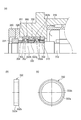
- a rotating shaft (30) a rotating shaft; Front and rear bearings that respectively support the rotary shaft rotatably with respect to the housing; With A spindle device in which the rotating shaft and inner rings of the front and rear bearings are fitted with an interference of zero or more, A pair of inner ring spacers disposed opposite to both side surfaces of at least one inner ring of the front and rear bearings and externally fitted to the rotary shaft; The inner ring spacer has a hook-like protrusion that protrudes in the axial direction from the outer peripheral side and is fitted onto the shoulder of the outer peripheral surface of the inner ring, and has a smaller thermal expansion coefficient and a higher specific elastic modulus than the inner ring.
- a spindle device characterized by being formed from.
- the outer peripheral surface of the shoulder portion of the inner ring has an outer peripheral taper portion whose diameter gradually decreases toward the axial end portion
- the inner peripheral surface of the flange-shaped protrusion of the inner ring spacer has an inner peripheral taper portion whose diameter gradually increases toward the axial end
- the spindle device according to (30) wherein the outer peripheral taper portion of the inner ring and the inner peripheral taper portion of the flange-shaped protrusion of the inner ring spacer are fitted.
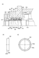
- the inner ring spacer has a main body part that is formed in an annular shape and is fitted on the rotation shaft, and the hook-shaped protrusion part that is formed separately from the main body part,
- the spindle apparatus according to (30) or (31), wherein the hook-shaped protrusion is fastened and fixed to the outer peripheral surface of the main body.
- the spindle device according to any one of (30) to (32), wherein the hook-shaped protrusion is formed of a plurality of protrusions that are separated in the circumferential direction.
- the spindle device according to any one of (30) to (34), wherein the inner ring spacer is formed of a carbon fiber composite material.
- the spindle device according to (35), wherein, in addition to the inner ring spacer, the rotating shaft is made of a carbon fiber composite material.
- the main spindle device includes a motor built-in in which a motor having a rotor fitted to the rotary shaft between the front and rear bearings and a stator arranged around the rotor is arranged.
- the spindle apparatus according to any one of (30) to (36), characterized by being a spindle apparatus of the type.
- the rotation shaft is disposed on the first cylindrical member made of a metal material and the outer peripheral surface of the first cylindrical member, the rotor is fitted to the outer peripheral surface, and the metal material of the first cylindrical member
- a second cylindrical member made of a material having a higher specific elastic modulus and a smaller linear expansion coefficient. Therefore, the second cylindrical member can suppress the temperature rise of the rotating shaft and the bearing due to the heat generated by the rotor, and the processing accuracy can be improved.
- a third cylinder made of a metal material is disposed on the outer peripheral surface at a position axially spaced from the outer peripheral surface to which the rotor of the second cylindrical member is fitted, and the inner ring of the front or rear bearing is fitted to the outer peripheral surface.
- a member thereby, the surface hardness of the third cylindrical member and the inner ring of the bearing can be made equal, the interference fit between them can be easily performed, and when the bearing is replaced, the mating surface Occurrence of defects such as scratches and scratches can be suppressed.
- the heat generated in the bearing from the fitting portion of the third cylindrical member and the inner circumferential surface of the bearing inner ring (the entire circumferential surface of the fitting portion becomes the heat transfer area) is passed through the inner ring spacer, One cylindrical member can be transmitted. That is, it is possible to suppress the occurrence of troubles such as seizure due to heat stagnating in the bearing inner ring and excessive preload due to the temperature difference between the bearing inner and outer rings.
- a cylindrical member having a smaller heat transfer coefficient than the rotating shaft is disposed between the rotating shaft and the rotor. This makes it difficult for the heat generated by the rotor to be transmitted to the inner ring of the front and rear bearings via the rotating shaft and further the rotating shaft, and the temperature difference between the inner and outer rings can be suppressed to maintain an appropriate preload. The occurrence of seizure of the bearing can be prevented. In addition, since the expansion of the rotating shaft itself is suppressed, good machining accuracy can be obtained.
- the member having a smaller heat transfer coefficient than the rotating shaft is partially interposed on either one of the opposed surfaces of the rotor sleeve and the rotating shaft, so that the rotor generates heat.
- the temperature difference between the inner and outer rings can be suppressed, and appropriate preload can be maintained, preventing the occurrence of seizure of the bearing can do.
- the opposing surfaces of the rotor sleeve and the rotating shaft other than the member having a low heat transfer coefficient can be fitted to each other, and appropriate management of the interference at the fitting portion is facilitated.
- the spindle device of the present invention between the front and rear bearings, the inner peripheral surface of the rotary shaft, and the outer peripheral surface of the rotary shaft away from the position where the rotor or the rotor sleeve is fitted. Since a member having a smaller heat transfer coefficient than the rotating shaft is arranged at least in one place, it is difficult for the heat transferred from the rotor to the rotating shaft to be transmitted to the inner ring of the front and rear bearings, resulting in a temperature difference between the inner and outer rings. Is suppressed, and an appropriate preload can be maintained, and the occurrence of seizure of the bearing can be prevented.
- the housing in which the front and rear bearings that rotatably support the rotating shaft are disposed includes at least a metal inner sleeve that fits around the rear bearing, and an inner sleeve. And an outer sleeve made of a carbon fiber composite material that fits outside, so that the heat from the rotating shaft is hardly transmitted to the machine side bracket by the action of the outer sleeve formed of a carbon fiber composite material having a low thermal conductivity. It is possible to perform high-accuracy processing by suppressing thermal deformation due to temperature rise on the machine side.
- the bearing sleeve fitted into the housing by clearance fitting has at least an annular carbon fiber composite material having the same axial length as the bearing sleeve.
- the carbon fiber composite material has anisotropy depending on the orientation direction of the carbon fiber, and the clearance setting can be selected by arbitrarily changing the coefficient of thermal expansion. Therefore, if a decrease in the clearance due to the difference between the temperature rise of the bearing sleeve and the temperature rise on the housing side can be assumed, the fiber orientation direction and angle should be selected according to this to obtain the optimum coefficient of thermal expansion. This is superior to conventional materials (such as Invar).
- the inner ring spacer is provided opposite to at least one side surface of the inner ring of the front and rear bearings that rotatably supports the rotating shaft and is fitted on the rotating shaft.
- the seat has a hook-like protrusion that protrudes in the axial direction from the outer peripheral side and is fitted onto the outer peripheral surface of the shoulder of the inner ring, and is made of a material having a higher specific elastic modulus and a smaller thermal expansion coefficient than the inner ring.
- the expansion of the inner ring spacer due to the centrifugal force during high-speed rotation is suppressed, the inner ring is restrained by the hook-shaped protrusion of the inner ring spacer that is fitted around the outer peripheral surface of the inner ring shoulder, and the inner ring is subjected to centrifugal force expansion. Can be suppressed. Furthermore, the amount of radial thermal expansion of the inner ring spacer that accompanies the temperature rise of the spindle device is smaller than the amount of radial thermal expansion of the inner ring, so the inner ring is pressed down by the difference in the amount of thermal expansion to further increase the thermal expansion of the inner ring. Can be pressed in small. As a result, an increase in the internal load of the bearing can be suppressed and occurrence of seizure or the like can be prevented.
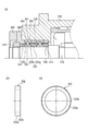
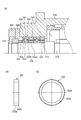
- (A) is sectional drawing which expands and shows the front side bearing vicinity of the main axis
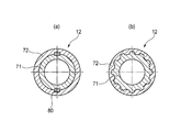
- (b) is a side view of a front side inner ring spacer
- (c) is a front view of a front side inner ring spacer. It is.
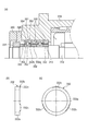
- (A) is sectional drawing which expands and shows the front side bearing vicinity of the main axis
- (b) is a side view of a front inner ring spacer
- (c) is a front view of a front inner ring spacer. It is.
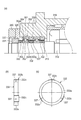
- (A) is sectional drawing which expands and shows the front side bearing vicinity of the main axis
- (b) is a side view of a front side inner ring spacer
- (c) is a front view of a front side inner ring spacer. It is.
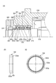
- (A) is sectional drawing which expands and shows the front side bearing vicinity of the main axis
- (b) is a side view of a front side inner ring spacer
- (c) is a front view of a front side inner ring spacer. It is.
- (A) is sectional drawing which expands and shows the front side bearing vicinity of the main axis
- (b) is a side view of a front side inner ring spacer
- (c) is a front view of a front side inner ring spacer. It is.
- (A) is sectional drawing which expands and shows the front side bearing vicinity of the main axis
- (b) is a side view of a front side inner ring spacer
- (c) is a front view of a front side inner ring spacer. It is.
- (A) is sectional drawing which expands and shows the front bearing vicinity of the main axis
- (b) is a side view of a front inner ring spacer
- (c) is a front view of a front inner ring spacer. It is.
- (A) is sectional drawing which expands and shows the front side bearing vicinity of the main axis
- (b) is a side view of a front side inner ring spacer
- (c) is a front view of a front side inner ring spacer. It is.
- FIG. 31 is a view for explaining a method of fastening the front inner ring spacer and the inner ring in the spindle device shown in FIG. 31, (a) is a view before tightening the nut, and (b) is a view after tightening the nut. .
- (A) is sectional drawing which expands and shows the front side bearing vicinity of the main axis
- (b) is a side view of a front side inner ring spacer
- (c) is a front view of a front side inner ring spacer. It is. It is sectional drawing which expands and shows the rear side bearing vicinity of the main axis
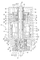
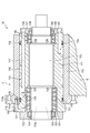
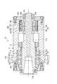
- the spindle device 10 is a motor built-in system, and a hollow rotary shaft 12 is provided at the axial center, and a draw bar 13 slides on the axis of the rotary shaft 12. It is freely inserted.
- the draw bar 13 urges the collet portion 15 that fixes the tool holder 14 in the counter-tool side direction (right direction in the figure) by the force of the disc spring 17, and the tool holder 14 has a tapered surface 18 of the rotary shaft 12. Mates with.
- a tool (not shown) is attached to the tool holder 14, and as a result, the rotary shaft 12 clamps the tool at one end (left side in the figure) so that the tool can be attached.
- the rotary shaft 12 is rotatably supported by the housing H by two rows of front bearings 50 and 50 that support the tool side and two rows of rear bearings 60 and 60 that support the opposite tool side.
- the housing H includes a front cover 40, a front bearing outer ring retainer 29, an outer cylinder 19, a rear housing 24, and a rear lid 26 in order from the tool side.
- the rotor 20 is fitted on the outer peripheral surface of the rotary shaft 12 between the front bearings 50 and 50 and the rear bearings 60 and 60 by shrink fitting.
- the stator 22 arranged around the rotor 20 is fixed to the outer cylinder 19 by fitting a cooling jacket 23 shrink-fitted to the stator 22 into the outer cylinder 19 constituting the housing H. Therefore, the rotor 20 and the stator 22 constitute a motor M, and by supplying electric power to the stator 22, a rotational force is generated in the rotor 20 and the rotating shaft 12 is rotated.
- Each front bearing 50 is an angular ball bearing having an outer ring 51, an inner ring 52, a ball 53 as a rolling element arranged with a contact angle, and a cage (not shown).
- the front bearings 50 and 50 (parallel combination) and the rear bearings 60 and 60 (parallel combination) are arranged to cooperate with each other to form a back combination.
- the outer rings 51, 51 of the front bearings 50, 50 are fitted into the outer cylinder 19, and are pivoted with respect to the outer cylinder 19 via the outer ring spacer 30 by the front bearing outer ring retainer 29 bolted to the outer cylinder 19. Positioned and fixed in the direction. Further, the inner rings 52, 52 of the front bearings 50, 50 are externally fitted to the rotating shaft 12, and are axially connected to the rotating shaft 12 via the inner ring spacer 32 by a nut 31 fastened to the rotating shaft 12. Positioning is fixed.
- the outer rings 61, 61 of the rear bearings 60, 60 are fitted inside a bearing sleeve 25 that is slidable in the axial direction with respect to the rear housing 24 inside the rear housing 24. It is positioned and fixed in the axial direction with respect to the bearing sleeve 25 via the outer ring spacer 34 by a rear bearing outer ring retainer 33 that is bolted to 25.
- a coil spring 38 for biasing the rear bearing outer ring retainer 33 toward the rear end is interposed between the rear housing 24 and the rear bearing outer ring retainer 33.
- the rear bearing outer ring retainer 33 and the bearing sleeve are interposed therebetween.
- outer rings 61 and 61, and the outer ring spacer 34 are integrally moved to the rear end side, the outer rings 61 and 61 are pressed in the axial direction, and a constant pressure preload corresponding to the urging force of the coil spring 38 is applied. It has come to be.
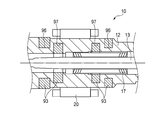
- Inner rings 62, 62 of the rear bearings 60, 60 are fitted on the rotary shaft 12, and are inserted into the inner ring spacer 36 and the detected portion 37 of the speed sensor by another nut 35 fastened to the rotary shaft 12. The positioning is fixed.
- the rotating shaft 12 is disposed on a first cylindrical member 71 made of a metal material such as high-tensile steel or carbon steel, and an outer peripheral surface of the first cylindrical member 71, and the rotor 20 is fitted on the outer peripheral surface.
- the inner rings 52, 52 of the front bearings 50, 50, the rotor 20, and the inner rings 62, 62 of the rear bearing 60 are fitted on the outer peripheral surface of the second cylindrical member 72. Further, the collet portion 15, the draw bar 13, and the disc spring 17 that move in the axial direction are accommodated inside the first cylindrical member 71.
- the first cylindrical member 71 is formed longer than the second cylindrical member 72 and regulates the axial positions of the small diameter portion 71a where the second cylindrical member 72 is disposed and the inner rings 52, 52 of the front bearings 50, 50.
- a large-diameter portion 71c having a male screw portion 71b to which the nut 31 is fastened.
- 71d is formed.
- a plurality of sliding contact surfaces 71e, 71f, 71g for slidably guiding the collet portion 15, the draw bar 13, and the disc spring 17 are formed on the inner peripheral surface of the first cylindrical member 71, and the tool side inner peripheral surface is formed. Is formed with a tapered surface 18 to which the tool holder 14 is attached.
- the carbon fiber composite material constituting the second cylindrical member 72 a material having a specific modulus greater than that of the metal material constituting the first cylindrical member 71, a smaller specific gravity, and a smaller thermal expansion coefficient (linear expansion coefficient) is used.
- the specific elastic modulus of the carbon fiber composite material is preferably at least twice, more preferably at least three times that of the metal material used in order to suppress expansion due to the centrifugal force of the rotating shaft 12 to an appropriate value.
- the carbon fiber composite material is anisotropic depending on the fiber direction, but the fiber direction is determined during molding in accordance with the direction of the load. Moreover, you may make it isotropic by making a fiber direction cross. Further, the fiber direction may be determined so that the specific elastic modulus in the circumferential direction is increased.
- first cylindrical member 71 and the second cylindrical member 72 As a method of joining the first cylindrical member 71 and the second cylindrical member 72, separately formed members may be joined by an interference fit or adhesion, or may be integrally formed. Furthermore, as shown in FIG. 2, in order to transmit sufficient rotational torque, a key 80 may be inserted between the first cylindrical member 71 and the second cylindrical member 72, or spline fitting may be performed.
- the carbon fiber composite material constituting the second cylindrical member 72 located on the radially outer side has a higher specific modulus, lower specific gravity, and heat than the metal material constituting the first cylindrical member 71 located on the inner side. Since the expansion coefficient is small, there is no gap in the fitting portion between them due to centrifugal force action and temperature change, and problems such as increased vibration during rotation and reduced rigidity do not occur.
- the carbon fiber composite material constituting the second cylindrical member 72 is a fabric in which yarns made of carbon fibers made of PAN (polyacrylonitrile) as a main raw material are arranged in parallel, or a fabric made of yarns made of carbon fibers.
- the sheet is manufactured by laminating a number of layers of a sheet formed by impregnating a thermosetting resin such as an epoxy resin containing a curing agent, winding the sheet around a cored bar, etc., and curing the sheet by heating.
- the tensile strength is 2060 MPa
- the tensile elastic modulus is 137 GPa
- the specific gravity is 1.55 g / cc.
- the tensile strength is equivalent or higher, and the specific gravity is about 1/5.
- the coefficient of thermal expansion can be reduced to ⁇ 5 to + 5 ⁇ 10 ⁇ 6 (K ⁇ 1 ) by optimizing the fiber direction and angle, so that it is 1/2 to 1 compared with the conventional carbon steel. / 10 or so.
- the rotor 20 and the second cylindrical member 72 are fitted with an interference due to shrink fitting. If the interference at the mating part decreases due to centrifugal force, rotational slippage due to torsional torque will occur, and if it becomes a clearance, the vibration of the main shaft may increase or machining may be defective. There is.
- the interference is preliminarily set in consideration of reduction of interference due to centrifugal force. For example, considering the reduction of interference due to centrifugal force, the interference is equal to or larger than (the centrifugal expansion amount of the inner diameter of the rotor 20 minus the centrifugal expansion amount of the outer diameter of the second cylindrical member 72). Set to.
- the linear expansion coefficient of the carbon fiber composite material is set to be smaller than that of the rotor 20 depending on the winding angle at the time of molding, it is considered that the interference is reduced due to the temperature increase of the rotor 20 and a clearance is formed. For this reason, it is preferable that the interference is set to be equal to or larger than (the above-mentioned centrifugal expansion amount + a decrease in interference due to temperature rise).
- a metal sleeve (not shown) may be interposed between the second cylindrical member 72 of the rotor 20, or as described in Patent Document 1, the outer peripheral surface of the carbon fiber composite material Alternatively, metal plating or ceramic may be sprayed.
- a spline or key may be formed on at least a part of the rotor 20 and the second cylindrical member 72 to integrally mold the carbon fiber composite material.
- the rotor 20 is externally fitted to the second cylindrical member 72.
- the heat generated by the rotor 20 is difficult to be transmitted to the inner rings 52 and 62 of the front and rear bearings 50 and 60 via the rotating shaft 12, and the temperature difference between the inner and outer rings 51, 52, 61 and 62 is suppressed, and an appropriate preload is achieved. Maintained.
- the expansion of the rotating shaft 12 itself is suppressed, good machining accuracy can be obtained.
- the rotating shaft 12 is provided with the 1st cylindrical member 71 which consists of metal materials inside the 2nd cylindrical member 72, the taper surface 18 to which the sliding contact surface 72f of the draw bar 13 and the tool holder 14 are attached is a 1st cylinder. It is comprised by the member 71, and the abrasion resistance in a specific site
- the rotor 20 is fitted to the second cylindrical member 72 with a margin, it is possible to prevent a gap from occurring even if a centrifugal force or a temperature rise of the rotor 20 occurs, and the rotor 20 rotates. In addition, an increase in vibration of the rotating shaft 12 can be suppressed.
- the first cylindrical member 71 includes a small-diameter portion 71a in which the second cylindrical member 72 is disposed, and a large-diameter portion 71c having a male screw portion 71b to which the nut 31 that regulates the axial position of the front bearing 50 is tightened. Therefore, the nut 31 can be securely fastened to the male screw portion 71b. Further, since the heat generation of the inner rings 52, 52 of the front bearings 50, 50 is transmitted from the inner ring spacer 32 and the nut 31 to the metal member such as the tool holder 14 via the first cylindrical member 71, the inner rings 52, 52 are transmitted. Temperature rise can be suppressed.
- the distance between the front bearing 50 and the rear bearing 60 becomes long, and the natural frequency in the radial direction of the rotating shaft tends to be small.
- it may be used in all areas up to the maximum number of revolutions, depending on the workpiece and machining conditions, rather than being used at a specific number of revolutions.
- the frequency is higher than the frequency at the maximum rotation, there is a possibility that machining cannot be performed due to the resonance action or abnormal vibration of the rotating shaft 12 in the resonance region may occur.
- a carbon fiber composite material having a larger specific modulus than that of a metal material is used. Therefore, in the case of the same bearing span, the natural frequency of the rotating shaft system (particularly, the natural frequency in the radial direction) is increased.
- the maximum number of rotations of the spindle device can be increased, and the machining rotation area can be widened.
- the carbon fiber composite material is excellent in vibration damping properties compared to the metal material, the dynamic rigidity of the rotating shaft 12 can be improved, and as a result, chatter vibration is hardly generated in severe processing conditions and finishing processing.
- the surface roughness is improved, the quality and glossiness of the processed surface are improved, and the processing accuracy is stabilized.
- the machining time and deceleration time of the spindle device depend on the size of the rotary inertia J.
- the rotational inertia of the hollow cylinder is given by the following calculation formula and is in a relationship proportional to the fourth power of the diameter.
- J (D4-d4) ⁇ L ⁇ ⁇ ⁇ ⁇ / 32
- D is the outer diameter of the hollow cylinder
- d is the inner diameter of the hollow cylinder
- L is the axial length of the hollow cylinder
- ⁇ is the specific gravity.
- the weight of the rotating shaft 12 as a whole decreases, and the rotating shaft 12 moves away from the center of rotation. Since the carbon fiber composite material is applied to the second cylindrical member 72, the rotational inertia can be reduced, the machining time and the deceleration time of the spindle device can be greatly shortened, and the machining tool replacement time can be shortened, thereby achieving high efficiency machining. Is possible.
- the front bearings 50 and 50 and the rear bearings 60 and 60 are fitted on the second cylindrical member 72 so that the surface of the rotary shaft 12 is infiltrated and adhered by the coolant. Rust is generated due to corrosion, and the rust enters the inside of the bearing, resulting in poor lubrication and preventing the bearing from seizing.
- the metal material is present on the inner diameter side or both end sides, the outer diameter of the rotating shaft and the reference surface for inner diameter finish grinding are secured, and finish grinding can be performed with high accuracy.
- a reference surface is provided on the carbon fiber composite material, wear and deformation are likely to occur, and it is difficult to ensure the coaxiality and roundness required for the high-speed main shaft. If the coaxiality and roundness are poor, the unbalance is large, causing vibration during high-speed rotation and poor machining accuracy.
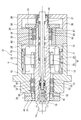
- the inner rings 52, 52 of the front bearings 50, 50 are fixedly fitted to the first cylindrical member 71 of the rotary shaft 12 with an interference.
- the sleeve 81 may be configured to be positioned and fixed in the axial direction with respect to the rotary shaft 12.
- the fixing sleeve 81 is incorporated into the first cylindrical member 71 by shrink fitting, and the fixing sleeve 81 is disassembled from the first cylindrical member 71 between the fixing sleeve 81 and the first cylindrical member 71. This is done by applying hydraulic pressure to the hydraulic chamber 83.
- the fixed sleeve 81 is configured to directly contact the inner ring 52 without using a spacer or the like, the axial length of the fixed sleeve 81 can be set long. Therefore, the axial length of the fitting portion between the fixed sleeve 81 and the first cylindrical member 71 is increased, and the contact area for heat conduction can be further increased.
- the heat generation of the inner ring 52 of the front bearing 50 can be more efficiently transmitted to the first cylindrical member 71 side via the fixed sleeve 81, so that the temperature of the inner ring 52 decreases and the inner ring 52 and the outer ring 51 The temperature difference can be reduced. Therefore, an increase in the preload during rotation of the front bearing 50 is reduced, and the PV values of the rolling contact portions of the inner ring 52 and the ball 53 and the outer ring 51 and the ball 53 can be suppressed, so that the front bearing 50 can be prevented from being seized. .
- the fixing sleeve 81 and the first cylindrical member 71 of the rotating shaft 12 are fitted to each other, the tilting of the fixing sleeve 81 with respect to the rotating shaft 12 is suppressed, and the inner ring 52 can be fixed uniformly. This makes it possible to improve the processing accuracy.
- the inner ring 52 is positioned and fixed in the axial direction by the nut 31 as in the above-described embodiment, the axial length of the nut 31 is ensured long, or the screw pitch is shortened (fine screw).
- specifications such as extremely small fitting gaps between the nut 31 and the first cylindrical member 71 and between the spacer 32 and the second cylindrical member 72 (for example, intermediate fitting) It is possible to increase the effective contact area of conduction and release the heat generated in the inner ring 52.
- the inner ring 52 can be fixed uniformly and processing accuracy can be ensured. It is.
- the front bearing 50 disposed on the tool side is a bearing that applies a cutting load, and a heat generation amount is increased by the load. Further, since the taper surface 18 for holding the tool holder 14 is provided on the tool side of the spindle device 10, a wall thickness is required to ensure the shaft rigidity and the natural frequency of the shaft system, and the front bearing 50 Tends to increase, and as a result, the dmn value of the front bearing 50 increases. Therefore, it is very effective to provide the fixed sleeve 81 as described above so as to efficiently release the heat generated by the front bearing 50.
- the rear bearing 60 disposed on the side opposite to the tool is not directly subjected to a cutting load as compared with the front bearing 50 and is smaller in size than the front bearing 50. Therefore, as in the above-described embodiment.
- a configuration in which the nut 35 is positioned in the axial direction may be used.
- the inner rings 62, 62 of the rear bearings 60, 60 have an interference with the first cylindrical member 71 without using the nut 35 as necessary, for example, when there is a margin for securing an axial space. Then, it may be configured to be positioned and fixed in the axial direction with respect to the rotating shaft 12 by a fixing sleeve fitted outside (not shown).
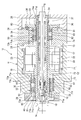
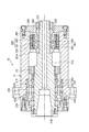
- the rotating shaft 12 includes a first cylindrical member 71 made of a metal material and a second cylindrical member 72 made of a carbon fiber composite material (CFRP), as in the first embodiment.
- the second cylindrical member 72 is disposed on the outer peripheral surface, and the inner rings 52, 52 of the front bearings 50, 50 and the inner rings 62, 62 of the rear bearings 60, 60 are fitted on the outer peripheral surface.
- three third cylindrical members 73 and 74 are fitted on the outer peripheral surface.
- the second cylindrical member 72 has an outer periphery in which the third cylindrical members 73 and 74 are disposed in the front portion and the rear portion that are positions spaced apart in the axial direction with respect to the axial intermediate portion in which the rotor 20 is fitted to the outer peripheral surface. Step portions 72a and 72b are provided so that the surface has a small diameter.
- the third cylindrical members 73 and 74 are fitted with the sleeve portions 73a and 74a on the outer peripheral surface having a small diameter in front of the stepped portion 72a and rearward of the stepped portion 72b, and the nuts of the sleeve portions 73a and 74a.
- Flange portions 73b, 74b extending radially outward from the side end portions are sandwiched between the axial side surfaces of the stepped portions 72a, 72b and the axial end surfaces of the inner rings 52, 62.
- the outer diameter of the flange portion 74b is set to be equal to or smaller than the outer diameter of the outer peripheral surface to which the rotor 20 is fitted so as not to interfere when the rotor 20 is fitted to the second cylindrical member 72.
- the third cylindrical members 73 and 74 are thin sleeves fitted to the outer peripheral surface of the second cylindrical member 72, and a metal material such as high-tensile steel or carbon steel whose surface hardness is equivalent to that of the first cylindrical member 71 is selected. It is preferred that The third cylindrical members 73 and 74 formed of such a thin sleeve are covered with the outer peripheral surface of the second cylindrical member 72 by shrink fitting, or by using a slight interference and bonding together. The outer peripheral surface of the member 72 is coupled.
- the inner rings 52, 52 of the front bearings 50, 50 and the inner rings 62, 62 of the rear bearings 60, 60 are fitted to the outer peripheral surfaces of the third cylindrical members 73, 74 with interference.
- the outer peripheral surface of the second cylindrical member 72 made of a carbon fiber composite material combined with the first cylindrical member 71 is subjected to a finishing process in order to ensure proper fitting with the third cylindrical members 73 and 74. Further, the outer peripheral surfaces of the third cylindrical members 73 and 74 made of a metal material are also subjected to a finishing process in order to ensure proper fitting with the inner rings 52 and 62.
- the carbon fiber composite material constituting the second cylindrical member 72 is superior to the metal material in terms of the specific elastic modulus, but the surface hardness tends to depend on the resin material as the base material and is relatively soft. Further, the fitting between the rotating shaft 12 and each of the inner rings 52 and 62 needs to be an interference fit with at least a clearance of 0 or more in order to increase the rigidity of the main shaft and improve the rotation accuracy of the shaft.
- the carbon fiber composite material (second cylindrical member 72) and the third cylindrical members 73 and 74 are coupled in a wide range in the axial direction.
- elastic deformation on the third cylindrical members 73 and 74 side can be expected. Can be reduced. Note that the contact surface pressure does not increase if both are bonded together as a small interference fit instead of a large interference fit.
- the fitting clearance between the third cylindrical members 73 and 74 and the inner rings 52 and 62 during operation is 0 to the interference side. It is desirable to set the fit when assembled.
- the inner rings of the bearings 50 and 60 are provided together with the nuts 31 and 35 and the inner ring spacers 32 and 36 on the opposite side.
- the axial fixing of the end can be an intermetal bond. Since the carbon fiber composite material uses a synthetic resin material as a base material, when the inner rings 52 and 62 and the carbon fiber composite material are tightly bonded with a certain load, the inner ring end portion and the contact portion of the carbon fiber composite material are between Elastic deformation tends to be large, and the tightening connection by the nuts 31 and 35 may be weakened.
- the third cylindrical members 73 and 74 with the flange portions 73b and 74b.
- the axial end surfaces of the inner rings 52 and 62 and the stepped portions 72a and 72b of the second cylindrical member 72 are not provided without providing the flange portions 73b and 74b. And may be directly joined. Further, the sleeve portions 73a and 74a and the flange portions 73b and 74b may be constituted by different members.
- the front and rear bearings 50 are provided on the outer peripheral surface of the second cylindrical member 72 on the outer peripheral surface at a position separated in the axial direction from the outer peripheral surface to which the rotor 20 is fitted.
- 60 are respectively fitted with the third cylindrical members 73, 74 made of a metal material, and the surface hardness of the third cylindrical members 73, 74 and the inner rings 52, 62 of the bearings 50, 60 is arranged.
- the amount of heat generated by the bearing is reduced by the inner ring spacer 32, from the fitting portion of the inner peripheral surface of the third cylindrical members 73, 74 and the bearing inner rings 52, 62 (the entire circumferential surface of the fitting portion becomes the heat transfer area). It can be transmitted to the front bearing nut 31 and the first cylindrical member 71 via 36. That is, it is possible to suppress the occurrence of problems such as seizure due to heat stagnating in the bearing inner rings 52 and 62 and excessive preload due to the temperature difference between the bearing inner and outer rings.
- the third cylindrical members 73 and 74 have flange portions 73b and 74b sandwiched between the axial side surfaces of the stepped portions 72a and 72b of the second cylindrical member 72 and the axial end surfaces of the inner rings 52 and 62. Even when the nuts 31 and 35 on the opposite side are strongly tightened, the inner ring ends of the bearings 50 and 60 can be fixed in the axial direction without causing damage such as cracking or chipping of the second cylindrical member 72.
- the third cylindrical members 73 and 74 are thin sleeves that fit on the outer peripheral surface of the second cylindrical member 72, but the third cylindrical members 73 and 74 are outer peripheral surfaces of the second cylindrical member 72. It may be a thin film member bonded to the surface by an electrical or chemical method. For example, when the following metal plating is used, a strong film can be formed.
- a base treatment layer for thermal spraying, a metal spray treatment layer, an intermediate plating layer, and an outermost plating layer By forming sequentially from the inside, a metal plating layer that is firmly bonded can be obtained.
- the base treatment layer has, for example, a thermal conductivity of 0.001 cal ⁇ cm ⁇ 1 ⁇ sec ⁇ 1 ⁇ deg ⁇ 1 or more, ⁇ ⁇ S ⁇ 0.05 ( ⁇ : thermal conductivity, S: m Carbon fiber composite material by blending a non-flat inorganic filler satisfying 2 / g) or a specially shaped metal or inorganic powder, such as an inorganic filler having complex irregularities on the surface, with a thermosetting resin It is formed by applying to the surface and thermosetting.
- the material of the metal spray-treated layer is not particularly limited as long as it can be electroplated on the surface, such as Cu, Ni, Al, and Fe.
- the material of the intermediate plating layer is selected from the viewpoint of sealing performance and corrosion resistance.
- Cu or Ni is particularly effective.
- the material of the outermost plating layer is appropriately selected depending on the application, but Ni and Cu are generally employed, and Cu plating is preferable when surface hardness is particularly required.
- Other configurations and operations are the same as those in the first embodiment.
- the inner rings 52, 52 of the front bearings 50, 50 are fixed sleeves that are fitted around the first cylindrical member 71 of the rotary shaft 12 with interference. 81 may be configured so as to be positioned and fixed in the axial direction with respect to the rotary shaft 12. In this case, the same effect as in FIG. 3 is obtained.
- the front bearings 50 and 50 and the rear bearings 60 and 60 are arranged so as to be a back combination. Even in such a spindle device, the same effects as those of the above-described embodiment can be obtained.
- the spindle device to which the present invention is applied is constituted by a pair of angular ball bearings so that a fixed position preload is applied to the front bearings 50, 50, and the rear bearing 60 is constituted by a single row cylindrical roller bearing. It may be something like that.
- the rotor 20 of the motor M is disposed so as to be integrally rotatable with the rotary shaft 12 via the rotor sleeve 70.
- the rotating shaft 12 is made of a metal material
- the rotor sleeve 70 is made of a carbon fiber composite material (CFRP).
- CFRP carbon fiber composite material
- CFRP a material having a thermal conductivity and a coefficient of thermal expansion smaller than that of the metal material, a specific elastic modulus higher than that of the metal material, and a specific gravity smaller than that of the metal material is used.
- the rotor 20 and the rotary shaft 12 have a strength equivalent to that of the metal. Can be insulated. As a result, the heat generated by the rotor 20 is not easily transmitted to the rotating shaft 12, and the thermal expansion of the rotating shaft 12 itself is suppressed, and good machining accuracy is maintained.
- the heat of the rotor 20 is difficult to be transmitted to the inner rings 52 and 62 of the front and rear bearings 50 and 60 via the rotating shaft 12, and the temperature increase of the inner ring temperature is suppressed, so that the inner and outer rings 51, 52, 61 and 62 are suppressed.
- the temperature difference can be reduced.
- problems such as bearing seizure due to an increase in internal load of the front and rear bearings 50 and 60 are prevented.
- the carbon fiber composite material for example, a woven fabric (sheet-like shape) made of PAN (polyacrylonitrile) as a main raw material, in which yarns made of carbon fibers are arranged in parallel, or made of yarns made of carbon fibers. ), A plurality of sheets impregnated with a thermosetting resin such as an epoxy resin containing a curing agent are superposed on each other, wound around a core metal, etc., and heated and cured.
- a thermosetting resin such as an epoxy resin containing a curing agent
- the tensile strength is 2060 MPa
- the tensile elastic modulus is 137 GPa
- the specific gravity is 1.55 g / cc.
- the tensile strength is equivalent or higher, and the specific gravity is about 1/5.
- the coefficient of thermal expansion can be reduced to ⁇ 5 to + 5 ⁇ 10 ⁇ 6 (K ⁇ 1 ) by optimizing the fiber direction and angle, so that it is 1/2 to 1 compared with the conventional carbon steel. / 10 or so.
- the heat of the outer rings 51 and 61 of the front and rear bearings 50 and 60 is radiated through the housing H to be fitted, whereas the heat of the inner rings 52 and 62 is hardly radiated, and the outer rings 51 and 61 are dissipated. It tends to be hotter. Therefore, the temperature management of the inner rings 52 and 62 is important for the internal load increase caused by the temperature difference between the inner and outer rings 51, 52, 61 and 62.
- the rotor 20 and the rotor sleeve 70, and the rotor sleeve 70 and the rotary shaft 12 are coupled by interference fit, adhesion, integral molding, or the like.
- a radial expansion during rotation due to a difference in radial expansion due to a difference in linear expansion coefficient of each member and a difference in expansion due to centrifugal force is provided.
- an appropriate margin should be provided so that at least no clearance is generated between the inner diameter of the rotating rotor 20 and the outer diameter of the rotor sleeve 70. It is preferable to select.
- the interference is equal to or larger than (the centrifugal expansion amount of the inner diameter of the rotor 20 ⁇ the centrifugal expansion amount of the outer diameter of the rotor sleeve 70).
- the linear expansion coefficient of the carbon fiber composite material is set smaller than that of the rotor 20 depending on the winding angle at the time of molding, it is considered that the interference is reduced due to the temperature rise of the rotor 20 and a clearance is generated. For this reason, it is preferable that the interference is set to be equal to or larger than (the above-mentioned centrifugal expansion amount + a decrease in interference due to temperature rise).
- the specific elastic modulus of the carbon fiber composite material is preferably at least twice, more preferably at least three times that of the metal material used in order to suppress expansion due to the centrifugal force of the rotating shaft 12 to an appropriate value. It is good.
- the carbon fiber composite material is anisotropic depending on the fiber direction, but the fiber direction is determined during molding in accordance with the direction of the load. Moreover, you may make it isotropic by making a fiber direction cross. Further, the fiber direction may be determined so that the specific elastic modulus in the circumferential direction is increased.
- the carbon fiber composite material has a thermal conductivity and a coefficient of thermal expansion smaller than that of the metal material, has a higher specific modulus than that of the metal material, and has a specific gravity smaller than that of the metal material. There is no gap in the fitting portion between the rotor sleeve 70 and the rotating shaft 12, and there is no problem that vibration during rotation increases or rigidity decreases.
- the heat conduction between the front bearing 50 and the rear bearing 60 that rotatably support the rotary shaft 12 is greater than that of the rotary shaft 12. Since the rotor 20 is externally fitted and fixed to the rotary shaft 12 via the rotor sleeve 70 formed of a carbon fiber composite material having a small rate, the heat generated by the rotor 20 is transmitted via the rotary shaft 12 and further via the rotary shaft 12.
- the temperature difference between the inner and outer rings 51, 52, 61, 62 can be suppressed, and an appropriate preload can be maintained, and the dmn value is 1 million. Even in the above high-speed rotation, it is possible to prevent the bearings 50 and 60 from being seized. Further, since the expansion of the rotary shaft 12 itself is also suppressed, good machining accuracy can be obtained.
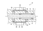
- the rotor sleeve 70a disposed between the rotor 20 and the rotating shaft 12 is made of metal.
- An annular outward convex portion 92 is formed on the outer peripheral surface of the fitting portion of the rotating shaft 12 into which the rotor sleeve 70a is fitted so as to define a plurality of annular grooves 91.
- a carbon fiber composite material (CFRP) 93 is disposed in each annular groove 91 in a ring shape, and is integrally fixed to the rotating shaft 12 by tight fitting, bonding, or integral molding.
- the carbon fiber composite material As the carbon fiber composite material (CFRP), a material having a heat transfer coefficient and a coefficient of thermal expansion smaller than those of the metal material, a specific elastic modulus higher than that of the metal material, and a specific gravity smaller than that of the metal material is used.
- the carbon fiber composite material 93 having a small heat transfer coefficient is disposed in the plurality of annular grooves 91 fitted into the rotor sleeve 70a, and the contact area between the rotor sleeve 70a and the metal of the rotary shaft 12, that is, the heat conduction area.
- the heat of the rotor 20 is difficult to be transmitted to the inner rings 52 and 62 of the front and rear bearings 50 and 60 via the rotating shaft 12, and the temperature increase of the inner ring temperature is suppressed, so that the inner and outer rings 51, 52, 61 and 62 are suppressed.
- the temperature difference can be reduced. Thereby, troubles such as seizure of the bearing due to an increase in internal load of the front and rear bearings 50 and 60 can be prevented while having the same strength as that of the metal.
- the opposing surface of the rotor sleeve 70a and the rotating shaft 12 other than the position where the carbon fiber composite material 93 having a low heat transfer coefficient is located that is, the inner peripheral surface of the rotor sleeve 70a, and the annular outward convex portion of the rotating shaft 12 With 92, the fitting between metals is left.
- the metal rotor sleeve 70a is fitted only with the carbon fiber composite material 93 which has a lower surface hardness than the metal and is easily elastically deformed, it is difficult to properly manage the fit.
- the metal fitting between the annular outward convex portion 92 of the rotating shaft 12 and the rotor sleeve 70a it is easy to properly manage the interference in the fitting portion. Become.
- the carbon fiber composite material 93 for example, a woven fabric (sheet) formed by parallelly arranging yarns made of carbon fibers mainly made of PAN (polyacrylonitrile), or yarns made of carbon fibers.
- the sheet is manufactured by laminating a large number of sheets impregnated with a thermosetting resin such as an epoxy resin containing a curing agent, winding the sheet around a cored bar, etc., and heating and curing the sheet.
- the carbon fiber composite material 93 is anisotropic in the fiber direction, but the fiber direction can be determined in accordance with the load direction, and should be used isotropically by crossing the fiber directions during molding. .
- the tensile strength is 2060 MPa
- the tensile elastic modulus is 137 GPa
- the specific gravity is 1.55 g / cc.
- the coefficient of thermal expansion can be reduced to ⁇ 5 to + 5 ⁇ 10 ⁇ 6 (K ⁇ 1 ) by optimizing the fiber direction and angle, so that it is 1/2 to 1 compared with the conventional carbon steel. / 10 or so.
- the ratio between the annular groove 91 of the rotating shaft 12 and the annular outward projecting portion 92 in other words, the contact area between metals in the fitting portion between the rotor sleeve 70a and the rotating shaft 12, and the metal and carbon fiber composite.
- the ratio of the contact area with the material 93 is determined based on the balance between the heat insulating effect and the coupling strength in the fitting portion between the rotor sleeve 70a and the rotating shaft 12.
- the heat of the outer rings 51 and 61 of the front and rear bearings 50 and 60 is radiated through the housing H to be fitted, whereas the heat of the inner rings 52 and 62 is hardly radiated, and the outer rings 51 and 61 are dissipated. It tends to be hotter. Therefore, the temperature management of the inner rings 52 and 62 is important for the internal load increase caused by the temperature difference between the inner and outer rings 51, 52, 61 and 62.
- the metal rotor sleeve 70a and the rotor 20 are joined by tight fitting, bonding, or integral molding.
- the rotor 20 formed by laminating a plurality of silicon steel plates is fitted to the shaft portion in which the outward convex portion 92 made of metal and the carbon fiber composite material 93 are mixed by an interference fit
- the rotor 20 is fitted to the outward convex portion 92.
- the fit will vary between the silicon steel plate to be fitted and the silicon steel plate fitted with the carbon fiber composite material 93 having a surface hardness lower than that of the metal.
- the balance between the plurality of silicon steel plates may be shifted and affect the performance of the motor M.
- the rotor 20 is fitted to the rotary shaft 12 via the rotor sleeve 70a, so that the fit does not vary and the interference is easily managed.
- the rotor sleeve 70a is provided between the rotor 20 and the rotary shaft 12, and the outer peripheral surface of the rotary shaft 12 facing the rotor sleeve 70a. Since the carbon fiber composite material 93 which is a member having a smaller heat transfer coefficient than the rotating shaft 12 is partially interposed, the heat generation of the rotor 20 is caused by the front bearing 50 via the rotating shaft 12 and the rotating shaft 12.
- the temperature difference between the inner and outer rings 51, 52, 61, 62 can be suppressed, and an appropriate preload can be maintained, and seizure of the bearings 50, 60 occurs. Can be prevented. Further, since the expansion of the rotary shaft 12 itself is also suppressed, good machining accuracy can be obtained.
- annular outward convex portion 92 is formed on the outer peripheral surface of the rotating shaft 12 so as to define a plurality of annular grooves 91, and the carbon fiber composite having a smaller heat transfer coefficient than the rotating shaft 12 is formed in the plurality of annular grooves 91.
- the material 93 is disposed, and the inner peripheral surface of the rotor sleeve 70a and the annular outward convex portion 92 of the rotating shaft 12 are fitted with an interference fit.
- the rotation shaft 12 and the rotor sleeve 70a can be stably fitted to each other.
- the member having a heat transfer coefficient smaller than that of the rotating shaft 12 is formed from the carbon fiber composite material, heat transfer from the rotor 20 can be efficiently suppressed.
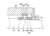
- FIG. 9 is a cross-sectional view of the main part of a spindle device according to a modification of the fourth embodiment.
- the arrangement position of the carbon fiber composite material 93 is opposite to that of the fourth embodiment, and a plurality of annular grooves 94 are defined on the inner peripheral surface of the metal rotor sleeve 70a.
- An annular inward convex portion 95 is formed.
- a carbon fiber composite material (CFRP) 93 is arranged in a ring shape in each annular groove 94, and is joined by tight fitting, adhesion, or integral molding.
- the carbon sleeve composite 93 having a small heat transfer coefficient is partially disposed on the inner peripheral surface of the rotor sleeve 70a to reduce the contact area between the rotor sleeve 70a and the rotating shaft 12, and thus the rotor sleeve.
- the heat transfer area from 70a to the rotating shaft 12 is reduced to suppress the heat of the rotor 20 transmitted to the rotating shaft 12 via the rotor sleeve 70a.
- the interference between the metal and the inward projection 95 of the rotor sleeve 70a and the outer peripheral surface of the rotary shaft 12 is left, and the rotary shaft 12 and the rotor sleeve 70a are fitted with an interference fit. Management becomes easy. Furthermore, by forming the carbon fiber composite material 93 as a separate member, the rotor sleeve 70a provided with the carbon fiber composite material 93 can be shared with other spindle devices.
- the rotor 20 is directly fitted and fixed to the approximate center of the rotating shaft 12 in the axial direction.
- a pair of outer circumferential annular grooves 96 are formed on the outer peripheral surface of the rotating shaft 12 that is separated from both sides in the axial direction from the position where the rotor 20 is fitted, and a pair of inner grooves are formed on the inner peripheral surface of the rotating shaft 12.
- a circumferential annular groove 97 is formed.
- a carbon fiber composite material (CFRP) 93 having a heat transfer coefficient smaller than that of the rotary shaft 12 is arranged in a ring shape in each of the outer peripheral side annular groove 96 and the inner peripheral side annular groove 97, and is tightly fitted, bonded, or integrally formed.
- the rotating shaft 12 is integrally coupled.
- the heat of the rotor 20 is hardly transmitted to the inner rings 52 and 62 of the front and rear bearings 50 and 60 via the rotating shaft 12, and the inner and outer rings 51, 52, 61, 62 are suppressed by suppressing the temperature rise of the inner ring.
- the temperature difference can be reduced.
- problems such as bearing seizure due to an increase in internal load of the front and rear bearings 50 and 60 can be prevented.
- the rotor 20 is fitted between the front and rear bearings 50 and 60 and the inner peripheral surface of the rotary shaft 12. Since the carbon fiber composite material 93 having a smaller heat transfer coefficient than the rotation shaft 12 is disposed on the outer peripheral surface of the rotation shaft 12 away from the position, the heat transmitted from the rotor 20 to the rotation shaft 12 is transferred to the front side and the rear side. It becomes difficult to transmit to the inner rings 52 and 62 of the bearings 50 and 60, the temperature difference between the inner and outer rings 51, 52, 61 and 62 can be suppressed, and an appropriate preload can be maintained, and seizure of the bearings 50 and 60 can be prevented. can do. Further, since the carbon fiber composite material 93 integrally bonded to both the annular grooves 96 and 97 has a strength equal to or higher than that of a metal, the strength of the rotating shaft 12 does not decrease.
- the rotor 20 can be externally fitted to the rotary shaft 12 via a rotor sleeve.
- the outer peripheral side annular groove 96 and the inner peripheral side annular groove 97 have substantially the same width and are formed at the same position in the axial direction, but are not limited to this. That is, the carbon fiber composite material 93 is formed between the front and rear bearings 50 and 60, and the outer peripheral surface of the rotary shaft 12 away from the position where the inner peripheral surface of the rotary shaft 12 and the rotor 20 or the rotor sleeve are fitted. What is necessary is just to arrange
- FIG. 11 is a cross-sectional view of a main part of a spindle device according to a modification of the fifth embodiment.
- the inner circumferential annular groove 97 of the rotary shaft 12 is disposed at a position overlapping the rotor 20 in the axial direction.
- the inner circumferential annular groove 97 is formed so as to overlap in the radial direction with the outer circumferential annular groove 96 formed on both axial sides of the rotor 20.
- a carbon fiber composite material 93 having a small heat transfer coefficient is integrally coupled to the rotary shaft 12 by tight fitting, bonding, or integral molding in the outer circumferential annular groove 96 and the inner circumferential annular groove 97. Therefore, the heat conduction area between the fitting portion of the rotating shaft 12 with the rotor 20 and the front bearing 50 and the rear bearing 60 is reduced, and the temperature of the inner rings 52 and 62 of the front and rear bearings 50 and 60 is increased. The temperature can be effectively suppressed.
- the fourth embodiment and the fifth embodiment can be applied in combination.
- the rotor sleeve 70a in which the carbon fiber composite material 93 is arranged in a ring shape in the annular groove 94 provided on the inner peripheral surface is provided on the rotating shaft 12. Is fitted to the outer peripheral surface.
- a carbon fiber composite material 93 is disposed on the inner circumferential side annular groove 97 formed on the rotary shaft 12 so as to overlap the fitting portion with the rotor sleeve 70a in the axial direction.
- the carbon fiber composite material 93 provided on the rotor sleeve 70a and the rotary shaft 12 allows the fitting portion between the rotor sleeve 70a and the rotary shaft 12, the front bearing 50, and the rear In the rotary shaft 12 between the side bearings 60, the heat conduction area is reduced, and the temperature rise of the inner rings 52, 62 of the front and rear bearings 50, 60 is suppressed.
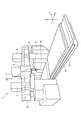
- FIG. 13 is a schematic perspective view of a portal machining center to which the spindle device of this embodiment is applied
- FIG. 14 is a cross-sectional view of the spindle device in FIG.
- a table 3 is supported on a bed 2 so as to be movable in the X-axis direction, and a pair of columns 4 are erected on both sides of the bed 2.
- a cross rail 5 is installed on the upper end of the column 4, and a saddle 6 is provided on the cross rail 5 so as to be movable in the Y-axis direction.
- the saddle 6 also supports a ram 7 that can be moved up and down in the Z-axis direction.
- the spindle device 10 of the present invention can be rotated and indexed around the Y axis and the Z axis.
- a spindle head 8 to be held is mounted.
- a tilt mechanism (not shown) is provided in the two support arms 8 a of the spindle head 8, and the spindle device 10 is rotationally indexed around the Y axis via the bracket 9 by this tilt mechanism.
- the spindle device 10 supports a housing H fitted in the bracket 9, a rotating shaft 113 inserted into the housing H, and the rotating shaft 113 rotatably with respect to the housing H.
- the rotating shaft 113 is formed in a hollow shape, and includes a draw bar extending in the axial direction, a collet provided on the leading end side of the draw bar, and between the draw bar and the rotating shaft 113, and the collet is A disc spring (both not shown) is drawn in to the tool side.
- the tool holder mounted on the collet is pulled into the opposite tool side (right side in FIG. 14), and is thus fitted to the taper surface 113a formed on the tool side inner peripheral surface of the rotary shaft 113. Is attached to the rotating shaft 113.
- the rotary shaft 113 is rotatable to the housing H by four rows of front bearings 150 that support the tool side (left side in FIG. 14) and two rows of rear bearings 160 that support the opposite tool side. It is supported.
- the housing H includes a metal inner sleeve 111 that fits around the plurality of front bearings 150 and the rear bearing 160, and an outer sleeve 112 made of a carbon fiber composite material that fits around the inner sleeve 111. Is fixedly fitted to the inner sleeve 111 by an interference fit or a combination of a clearance fit and an adhesive.
- the outer sleeve 112 is fixed to the bracket 9 of the spindle head 8 on the machine side by inserting a bolt (not shown) through a bolt hole 114 of a flange 112a provided at the front end in the axial direction.
- a cooling groove 116 that forms a coolant supply path 115 for circulating and supplying the coolant spirals on the outer peripheral surface of the inner sleeve 111 at the fitting portion between the inner sleeve 111 and the outer sleeve 112. Is formed. Both ends in the axial direction of the cooling groove 116 communicate with a supply hole 117 extending along the axial direction on the inner diameter side of the cooling groove 116, and the supply hole 117 is a rear bearing described later. It communicates with the refrigerant supply / discharge port 130 formed in the outer ring retainer 127.
- a refrigerant supply device (not shown) is connected to the refrigerant supply / discharge port 130 via a pipe, and a refrigerant such as cooling water is circulated and supplied to the refrigerant supply path 115 via the supply hole 117 to cool the inner sleeve 111. To do.
- O-ring grooves 118 are formed at both ends in the axial direction of the outer peripheral surface of the inner sleeve 111, and an O-ring 119 as a seal member is attached to the O-ring groove 118. Therefore, both sides in the axial direction of the refrigerant supply path 115 are sealed from the outside by the O-ring 119, and leakage of the refrigerant is prevented.
- Each front bearing 150 is an angular ball bearing having an outer ring 151, an inner ring 152, a ball 153 as a rolling element arranged with a contact angle, and a cage (not shown).
- the four rows of front bearings 150 are arranged such that two rows of front bearings 150 are combined in parallel from the front in the axial direction (left side in the figure) to form a pair, and each pair is a back combination. Further, the two rows of rear bearings 160 are arranged so as to form a back surface combination.
- each front bearing 150 is fitted in the inner sleeve 111 and is abutted against a stepped portion 120 formed on the inner sleeve 111 on the side opposite to the tool from the outer ring 51 and the front end of the inner sleeve 111 in the axial direction. It is positioned and fixed in the axial direction via an outer ring spacer 121 by a front bearing outer ring presser 122 fastened and fixed to the outer ring. Further, the inner ring 152 of each front bearing 150 is fitted on the rotating shaft 113, but is abutted against a step portion 123 formed on the rotating shaft 113 on the side opposite to the inner ring 152 and fastened to the rotating shaft 113. The nut 124 is positioned and fixed in the axial direction with respect to the rotary shaft 113 via the inner ring spacer 125.
- each rear bearing 160 is fitted into the inner sleeve 111, and between the outer ring 161 and the stepped portion 126 formed on the inner sleeve 111 on the tool side, and the rear end of the inner sleeve 111 in the axial direction.
- a gap in the axial direction is formed between the rear bearing outer ring presser 127 that is fastened and fixed to the outer ring.
- each rear bearing 160 is fitted on the rotary shaft 113, is abutted against a step portion 128 formed on the rotary shaft 113 on the tool side of the inner ring 162, and is fastened to the rotary shaft 113.
- the nut 129 is positioned and fixed.
- the spindle device 10 of the present embodiment configured as described above is fixed to the machine-side bracket 9 via an outer sleeve 112 made of a carbon fiber composite material having a thermal conductivity smaller than that of metal.
- heat generated on the spindle device 10 side is hardly transmitted to the bracket 9 on the machine side, thermal deformation on the machine side can be suppressed, and machining with high accuracy is possible.
- a motor built-in type main shaft device in which a driving motor is built in the main shaft device 10 since the heat generated by the rotor and the stator is difficult to be transmitted to the machine side, the effect of the present invention is great.
- the outer sleeve 112 having a relatively large volume is formed of a carbon fiber composite material having a small specific gravity, the mass of the spindle device 10 is reduced.
- the inertia of the feed shaft on which the spindle device 10 is mounted can be reduced, and the movement acceleration of the spindle device 10 can be increased. Therefore, the tool change time, the movement time of the spindle device 10 to the machining site, and the like can be shortened to increase the actual machining time, and the machining efficiency is improved.
- the inertia of the spindle apparatus 10 can be reduced, so that turning acceleration is improved and machining with high efficiency is possible.
- chatter may occur when machining difficult-to-cut materials such as titanium or when the sharpness of the blade is lowered.
- the carbon fiber composite material has good vibration damping characteristics, the spindle device 10 Side vibration is difficult to be transmitted to the bracket 9 on the machine side, and resonance phenomenon is prevented, so that high machining accuracy is maintained.
- the motor built-in spindle device 10 in which the drive motor is built in the spindle device 10 is effective because the heat generated by the motor can be suppressed from being transmitted to the machine side. Furthermore, since the specific gravity of the carbon fiber composite material is small, the mass and inertial force of the spindle device 10 can be reduced, and the spindle head can be moved at a higher speed, thereby improving the production efficiency.
- the refrigerant supply path 115 that circulates and supplies the refrigerant is disposed in the fitting portion between the inner sleeve 111 and the outer sleeve 112, so that the inner sleeve 111 can be effectively used by the refrigerant. Further, combined with the low thermal conductivity of the carbon fiber composite material, the temperature rise on the machine side is suppressed. As a result, thermal deformation due to temperature rise on the machine side can be suppressed, and processing with high accuracy becomes possible.
- the O-rings 119 that seal the refrigerant supply path 115 from the outside are disposed at both axial ends of the fitting portion between the inner sleeve 111 and the outer sleeve 112. The refrigerant leakage from the refrigerant supply path 115 can be reliably prevented.
- the spindle device 10 of the seventh embodiment has the same basic configuration as that of the spindle device 10 of the sixth embodiment, but the inner sleeve 111 and the outer sleeve 112 are fitted by a clearance fit, and the inner sleeve 111 has its axis. The difference is that the flange 111 a formed at the front end in the direction is fastened to the outer sleeve 112 by a bolt 131.
- the metallic inner sleeve 111 thermally expands in the radial direction.
- the outer sleeve 112 made of a carbon fiber composite material is less likely to expand than the inner sleeve 111, and as a result, the inner sleeve 111 is pressed from the outside and is fitted to the front and rear bearings 150 and 160 that fit inside the inner sleeve 111. May have an effect.
- the inner sleeve 111 and the outer sleeve 112 are fitted with a proper gap, so that the inner sleeve 111 can be prevented from being pressed by the outer sleeve 112, and the inner sleeve 111 can be prevented from being pressed.
- the fitting clearance between the sleeve 111 and the front and rear bearings 150 and 160 is reduced, and the influence on the internal load of the bearings 150 and 160 is reduced.
- Other functions and effects are the same as those of the spindle device 10 of the sixth embodiment.
- the housing H of the spindle device 10 of the present embodiment includes an inner sleeve 111, an outer sleeve 112, and a front bearing housing 135.
- the front bearing housing 135 is made of metal, is fixed to the axially forward end surface 112b of the inner sleeve 111, and is disposed axially forward of the inner sleeve 111 and the outer sleeve 112. In other words, the front bearing housing 135 is configured not to be fitted into the outer sleeve 112.
- the four rows of front bearings 150 are arranged to be fitted in the front bearing housing 135 and cooperate with the two rows of rear bearings 160 arranged on the side opposite to the inner sleeve 111 to rotate the rotary shaft 113.
- the outer ring 151 of each front bearing 150 is fitted in the front bearing housing 135, but is abutted against a stepped portion 136 formed on the front bearing housing 135 on the side opposite to the outer ring 151, and the front bearing housing 135. It is positioned and fixed in the axial direction via an outer ring spacer 121 by a front bearing outer ring retainer 122 fastened to the front end in the axial direction.
- each front bearing 150 is fitted on the rotating shaft 113, but is abutted against a step portion 137 formed on the rotating shaft 113 on the side opposite to the inner ring 152 and fastened to the rotating shaft 113.
- the nut 124 is positioned and fixed in the axial direction with respect to the rotary shaft 113 via the inner ring spacer 125.
- the metal sleeve 111 is made as the temperature of the spindle device 10 increases.
- the inner sleeve 111, the rotating shaft 113, the outer ring 151, the inner ring 152, etc. are thermally expanded in the radial direction, but the outer sleeve 112 made of carbon fiber composite material is difficult to expand, and therefore the outer sleeve 112 presses the inner sleeve 111 from the outside. And the outer ring 151 is contracted. As a result, the internal load of the front bearing 150 may increase.
- the front bearing 150 disposed on the tool side is a bearing that applies a cutting load, it is necessary to set the inner diameter larger than that of the rear bearing 160 in order to ensure rigidity. Further, since the taper surface 113a for holding the tool is provided on the tool side of the spindle device 10, a wall thickness is required to ensure the shaft rigidity and the natural frequency of the shaft system, and the inner diameter of the front bearing 150 is increased. Becomes larger. Therefore, the front bearing 150 tends to have a larger dmn value than the rear bearing 160.
- the spindle device 10 of the present embodiment since the outer sleeve 112 made of a carbon fiber composite material is not externally fitted to the front bearing housing 135 in which each front bearing 150 is fitted, the pressing action from the outside is achieved. In addition, even during high-speed rotation, an increase in the internal load of the front bearing 150 described above can be suppressed, and occurrence of problems such as seizure can be suppressed.
- the front bearing housing 135 is fixed to the inner sleeve 111 made of a metal material, and there is no fitting portion with the outer sleeve 112 made of a carbon fiber composite material, which makes it difficult to select an appropriate fit, so that the design is easy. .
- the housing H further includes the front bearing housing 135 in the axial direction front of the inner sleeve 111 and the outer sleeve 112, and the front bearing 150 includes the front bearing housing 135. Therefore, the thermal expansion of the front bearing housing 135 is not limited by the outer sleeve 112 made of a carbon fiber composite material, and adverse effects on the front bearing 150 fitted inside the front bearing housing 135 can be suppressed. .
- sixth to eighth embodiments can also be applied to a motor built-in type spindle apparatus in which a driving motor is built in the spindle apparatus.
- the spindle apparatus of 9th Embodiment is demonstrated with reference to FIG.
- the main spindle device 10 is a motor built-in system, and a hollow rotary shaft 212 is provided at the axial center, and a draw bar 213 slides on the axis of the rotary shaft 212. It is freely inserted.
- the draw bar 213 urges the collet portion 215 that fixes the tool holder 214 in the counter-tool side direction (right direction in the drawing) by the force of the disc spring 217, and the tool holder 214 has a tapered surface 218 of the rotating shaft 212. Mates with.
- a tool (not shown) is attached to the tool holder 214.
- the rotary shaft 212 clamps the tool at one end (the left side in the figure) so that the tool can be attached.
- the rotary shaft 212 includes two rows of front bearings (fixed side bearings) 250 and 250 that support the tool side, and two rows of rear bearings (free side bearings) 260 and 260 that support the opposite tool side.
- the housing H is rotatably supported.
- the housing H includes a front cover 240, a front bearing outer ring retainer 229, a front housing 227, an outer cylinder 219, a rear housing 224, and a rear lid 226 in order from the tool side.
- the rotor 220 is fitted on the outer peripheral surface of the rotary shaft 212 between the front bearings 250 and 250 and the rear bearings 260 and 260 by shrink fitting.
- the stator 222 disposed around the rotor 220 is fixed to the outer cylinder 219 by fitting the cooling jacket 223 shrink-fitted to the stator 222 into the outer cylinder 219 constituting the housing H. Therefore, the rotor 220 and the stator 222 constitute a motor M, and by supplying electric power to the stator 222, a rotational force is generated in the rotor 220 and the rotating shaft 212 is rotated.
- Each front bearing 250 is an angular ball bearing having an outer ring 251, an inner ring 252, a ball 253 as a rolling element arranged with a contact angle, and a retainer (not shown), and each rear bearing 260.
- the outer rings 251, 251 of the front bearings 250, 250 are fitted into the front housing 227, and are pivoted with respect to the front housing 227 via the outer ring spacer 230 by a front bearing outer ring retainer 229 that is bolted to the front housing 227. Positioned and fixed in the direction. Further, the inner rings 252 and 252 of the front bearings 250 and 250 are fitted on the rotating shaft 212 and are axially connected to the rotating shaft 212 via the inner ring spacer 232 by a nut 231 fastened to the rotating shaft 212. Positioning is fixed.
- the outer rings 261, 261 of the rear bearings 260, 260 are fitted inside a bearing sleeve 225 that is slidable in the axial direction with respect to the rear housing 224 inside the rear housing 224.
- the outer rings 261 and 261 are in contact with the rear bearing outer ring retainer 233 that is bolted to the bearing sleeve 225, and are positioned and fixed in the axial direction with respect to the bearing sleeve 225 via the outer ring spacer 234. Has been.
- Inner rings 262 and 262 of the rear bearings 260 and 260 are externally fitted to the rotary shaft 212, and the detected portion 238 of the inner ring spacer 36 and the speed sensor 237 is moved by another nut 235 fastened to the rotary shaft 212. The positioning is fixed through.
- the front bearings 250 and 250 (parallel combination) and the rear bearings 260 and 260 (parallel combination) are arranged so as to form a back combination in cooperation with each other, and the front bearings 250 and 250 and the rear bearing 260, A constant pressure preload is applied to 260.
- An urging member 239 such as a spring is disposed between the rear housing 224 and the rear bearing outer ring retainer 233, and the rear bearing outer ring retainer 233 and the bearing sleeve 225 are arranged with respect to the rear housing 224. It becomes slidable in the axial direction.
- the bearing sleeve 225 is disposed on the outer diameter side thereof, and is disposed on the inner diameter side of the annular outer metal member 271 having an outer peripheral surface that is fitted to the rear housing 224, and is fitted to the outer rings 261 and 261.
- the outer metal member 271, the inner metal member 272, and the carbon fiber composite material 273 each have the same axial length as the bearing sleeve 225, and the bearing sleeve 225 is configured in a radial multilayer structure.
- the carbon fiber composite material 273 has a higher specific elastic modulus, a lower specific gravity, and a lower thermal expansion coefficient than the metal materials constituting the outer and inner metal members 271,272.
- the specific elastic modulus of the carbon fiber composite material preferably corresponds to the thermal expansion of the outer and inner metal members 271 and 272 that together form the bearing sleeve 225, and is preferably more than twice that of the metal material used. Is more than 3 times.
- the carbon fiber composite material is anisotropic depending on the fiber direction, but the fiber direction is determined during molding in accordance with the direction of the load. Moreover, you may make it isotropic by making a fiber direction cross. Further, the fiber direction may be determined so that the specific elastic modulus in the circumferential direction is increased.
- the carbon fiber composite material 273 is hardened on a woven fabric (sheet-like) formed of carbon fibers made of PAN (polyacrylonitrile) as a main raw material, or made of carbon fibers. It is manufactured by laminating a number of sheets impregnated with a thermosetting resin such as an epoxy resin containing an agent, winding the sheet around a cored bar, etc., and curing it by heating.
- a thermosetting resin such as an epoxy resin containing an agent
- the tensile strength is 2060 MPa
- the tensile elastic modulus is 137 GPa
- the specific gravity is 1.55 g / cc.
- the coefficient of thermal expansion can be set to -5 to + 5 ° ⁇ 10 -6 ° C by optimizing the fiber direction and angle, so that it is about 1/2 to 1/10 that of conventional carbon steel. Can be.
- the fiber direction and angle are optimized so that an appropriate thermal expansion coefficient is obtained so that the clearance between the two is not reduced. May be used.
- separately formed members may be joined by interference fitting or adhesion, or may be integrally formed.
- the expansion of the inner metal member 272 can be suppressed by the outer carbon fiber composite material 273. Therefore, it is possible to prevent the outer diameter of the bearing sleeve 225 from expanding and the gap between the rear housing 224 and the bearing sleeve 225 from decreasing.
- the inner metal member 272 uses a low expansion cast member having a linear expansion coefficient closer to that of the carbon fiber composite material 273, such as novinite, to suppress a decrease in the gap between the rear housing 224 and the bearing sleeve 225. Although it is more preferable, for example, even when the material has the same linear expansion coefficient as that of the rear housing 224, the effect can be exerted by the pressing action of the carbon fiber composite material 273. In addition, it is preferable that the thickness of the carbon fiber composite material 273 is thicker than that of the inner metal member 272 because the pressing action is further increased.
- the present embodiment by combining the rear bearing outer ring holder 233 and the outer rings 261 and 261 that are not in direct contact with the rear housing 224 and have a large heat capacity, heat is released to the outer ring holder 233 side. is there. As a result, the initial clearance of the sliding portion between the rear housing 224 and the bearing sleeve 225 can be reduced, and vibration at low speed (low heat generation) can be reduced while maintaining slidability. Further, expansion of the outer diameter of the bearing sleeve can be suppressed by heat generation during high-speed rotation, reduction of the gap can be suppressed, and sliding failure of the bearing sleeve can be prevented. Furthermore, since the carbon fiber composite material is excellent in damping property against vibration, vibration can be suppressed.
- the bearing sleeve 225 has a combination of the outer metal member 271 and the carbon fiber composite material 273, or the carbon fiber composite material 273 and the inner metal member 272, as in the tenth and eleventh embodiments. Or a carbon fiber composite material 273 alone.
- the outer peripheral surface of the bearing sleeve 225 may be configured by the outer metal member 271 or the carbon fiber composite material 273 as long as it satisfies the slidability with the rear housing 224. . Further, metal plating or ceramic may be sprayed on the outer peripheral surface of the carbon fiber composite material.
- the rotating shaft 212 includes two rows of front bearings (fixed side bearings) 250 and 250 that support the tool side, and two rows of rear bearings (free side bearings) 260 that support the counter tool side.
- 260 is rotatably supported by the housing H and is driven to rotate by an external driving force.
- the housing H includes a front bearing outer ring retainer 229, an outer cylinder 219, and a rear lid 226 in order from the tool side.
- the front bearings 250 and 250 and the rear bearings 260 and 260 are arranged so as to be a combination of the back surfaces, respectively, so that a fixed position preload is applied.
- the outer rings 251 and 251 of the front bearings 250 and 250 are fitted into the outer cylinder 219, and are pivoted with respect to the outer cylinder 219 via the outer ring spacer 230 by the front bearing outer ring retainer 229 that is bolted to the outer cylinder 219. Positioned and fixed in the direction.
- the inner rings 252 and 252 of the front bearings 250 and 250 are fitted on the rotating shaft 212 and are axially connected to the rotating shaft 212 via the inner ring spacer 232 by a nut 231 fastened to the rotating shaft 212. Positioning is fixed.
- the outer rings 261 and 261 of the rear bearings 260 and 260 are fitted into a bearing sleeve 225 that is slidable in the axial direction with respect to the outer cylinder 219, and are positioned and fixed in the axial direction with respect to the bearing sleeve 225. Yes.
- Inner rings 262 and 262 of the rear bearings 260 and 260 are externally fitted to the rotary shaft 212, and are positioned and fixed in the axial direction via the inner ring spacer 236 by other nuts 235 fastened to the rotary shaft 212. Yes.
- the bearing sleeve 225 is disposed on the outer diameter side thereof, and is disposed on the inner side of the carbon fiber composite material (CFRP) 281 having the outer peripheral surface fitted to the outer cylinder 219 and the carbon fiber composite material 281, and the outer ring 261. , 261 and a ring-shaped inner metal member 282 having an inner peripheral surface to be fitted in the radial direction multilayer structure.
- CFRP carbon fiber composite material
- the carbon fiber composite material 281 and the inner metal member 282 are joined by adhesion or shrink fitting.
- the finishing of the outer peripheral surface of the carbon fiber composite material 281 is preferably performed after joining with the inner metal member 282.
- the bearing sleeve 225 is provided with a detent portion 285 to prevent a slip in the circumferential direction between the housing 219 and the bearing sleeve 225 due to an increase in the friction torque of the rolling bearing 260 during acceleration / deceleration.
- the outer side of the bearing sleeve 225 is the carbon fiber composite material 281 and the inner side is the inner metal member 282, whereby the expansion of the inner metal member 282 can be suppressed by the carbon fiber composite material 281. Reduction of the gap with the sleeve 225 can be suppressed.
- the carbon fiber composite material 281 is disposed outside the bearing sleeve 225 having a large diameter. By doing so, the expansion of the bearing sleeve 225 can be effectively suppressed.
- FIG. 19 is a cross-sectional view of the spindle device 10 according to the eleventh embodiment of the present embodiment.
- the fit between the inner peripheral surface of the bearing sleeve 225, that is, the inner peripheral surface of the inner metal member 282, and the outer peripheral surfaces of the outer rings 261 and 261 of the rear bearings 260 and 260 is a clearance fit.
- the clearance between the bearing sleeve 225 and the outer rings 261 and 261 is set to be larger than the radial expansion of the outer rings 261 and 261 due to the centrifugal force action of the balls 263 and 263 when the bearings 260 and 260 rotate at a high speed.
- the increase in internal preload due to centrifugal force can be mitigated by expansion of the outer ring.
- both end surfaces of the outer rings 261 and 261 are connected to the inner metal so that the outer rings 261 and 261 do not slide in the circumferential direction inside the bearing sleeve 225.
- the member 282 is configured to be pressed by a shoulder 282a and an outer ring presser 284 that is bolted to the inner metal member 282.
- vibrations of the bearings 260 and 260 that are a concern due to the clearance fit can be prevented.
- Other configurations and operations are the same as those in the tenth embodiment.
- FIG. 20 is a cross-sectional view of the spindle device 10 according to a first modification of the eleventh embodiment of the present embodiment.
- the configuration of the bearing sleeve 225 is different from that of the eleventh embodiment. That is, the bearing sleeve 225 is disposed on the outer diameter side thereof, and is disposed on the inner side of the outer metal member 283 and the annular outer metal member 283 having an outer peripheral surface that fits the outer cylinder 219, and the outer rings 261 and 261 have a clearance.
- a carbon fiber composite material (CFRP) 281 having an inner peripheral surface to be fitted by fitting.
- the clearance between the bearing sleeve 225 and the outer rings 261 and 261 is the same as that of the eleventh embodiment in that the radii of the outer rings 261 and 261 due to the centrifugal force action of the balls 263 and 263 when the bearings 260 and 260 rotate at a high speed. Since it is set to be larger than the directional expansion, the outer ring expansion that relaxes the increase in internal preload due to the centrifugal force is allowed by this clearance. Therefore, the inner peripheral surface of the bearing sleeve 225 may be made of the carbon fiber composite material 281 as in the modified example. Further, in this case, both end surfaces of the outer rings 261 and 261 are configured to be held by the shoulder portion 281a of the carbon fiber composite material 281 and the outer ring presser 284 bolted to the bearing sleeve 225.
- FIG. 21 is a cross-sectional view of the spindle device 10 according to a second modification of the eleventh embodiment of the present embodiment.
- the entire bearing sleeve 225 is composed of the carbon fiber composite material 281.
- the clearances between the bearing sleeve 225 and the outer rings 261 and 261 are the same as in the eleventh embodiment, and the outer rings 261 and 261 due to the centrifugal force action of the balls 263 and 263 when the bearings 260 and 260 rotate at a high speed. Since the clearance is set to be larger than the radial expansion of the outer ring, the outer ring expansion that relaxes the increase in internal preload due to the centrifugal force is allowed by this clearance.
- a spindle device according to a twelfth embodiment will be described with reference to FIG.
- a hollow rotating shaft 312 made of a metal material, more specifically, a chromium molybdenum steel material (SCM material) is provided at the center in the axial direction.
- a draw bar (not shown) is slidably inserted into the shaft core of the rotating shaft 312. The drawbars urge the collet that fixes the tool holder (not shown) in the counter tool side direction (right direction in the figure) by the force of the disc spring, and the tool holder fits with the tapered surface of the rotating shaft 312. Match.
- a tool is attached to the tool holder, and as a result, the rotary shaft 312 clamps the tool at one end (the left side in the figure) so that the tool can be attached.
- the rotary shaft 312 is rotatably supported on the housing H by two rows of front bearings 350 and 350 that support the tool side, and two rows of rear bearings 360 and 360 that support the opposite tool side.
- the housing H includes a front cover 340, a front bearing outer ring retainer 329, an outer cylinder 319, a rear housing 324, and a rear lid 326 in order from the tool side.
- the rotor 320 is fitted on the outer peripheral surface of the rotating shaft 312 between the front bearings 350 and 350 and the rear bearings 360 and 360 of the rotating shaft 312 by shrink fitting.
- the stator 322 disposed around the rotor 320 is fixed to the outer cylinder 319 by fitting the cooling jacket 323 shrink-fitted to the stator 322 into the outer cylinder 319 constituting the housing H. Therefore, the rotor 320 and the stator 322 constitute a motor M, and by supplying electric power to the stator 322, a rotational force is generated in the rotor 320 and the rotating shaft 312 is rotated.
- Each front bearing 350 is an angular ball bearing having an outer ring 351, an inner ring 352, a ball 353 as a rolling element arranged with a contact angle, and a cage 354, and each rear bearing 360 An angular ball bearing having an outer ring 361, an inner ring 362, a ball 363 as a rolling element, and a cage 364.
- the front bearings 350 and 350 (parallel combination) and the rear bearings 360 and 360 (parallel combination) are arranged so as to cooperate with each other to form a rear combination.
- the outer rings 351 and 351 of the front bearings 350 and 350 are fitted into the outer cylinder 319 and are fixed to the outer cylinder 319 via the front outer ring spacer 330 by a front bearing outer ring presser 329 that is bolted to the outer cylinder 319. It is positioned and fixed in the axial direction.
- Inner rings 352 and 352 of the front bearings 350 and 350 are externally fitted to the rotary shaft 312 with zero or more interference, and rotate with the step portion 313 of the rotary shaft 312 via the plurality of front inner ring spacers 332. It is sandwiched between a nut 331 fastened to the shaft 312 and positioned with respect to the rotating shaft 312.
- the outer rings 361 and 361 of the rear bearings 360 and 360 are fitted into a bearing sleeve 325 that is slidable in the axial direction inside the rear housing 324 and are bolted to the bearing sleeve 325. It is positioned and fixed in the axial direction with respect to the bearing sleeve 325 via the rear outer ring spacer 334 by the rear bearing outer ring presser 333. Further, the inner rings 362 and 362 of the rear bearings 360 and 360 are externally fitted to the rotating shaft 312 with zero or more interference, and the rear inner ring spacer 336 is secured by another nut 335 fastened to the rotating shaft 312. The positioning is fixed with respect to the rotary shaft 312 via
- front and rear inner ring spacers 332 and 336 and the inner rings 352 and 362 of the front and rear bearings 350 and 360 will be described in detail. Since the front inner ring spacer 332 and the front bearing 350, and the rear inner ring spacer 336 and the rear bearing 360 have the same configuration, in the following description, the front inner ring spacer 332 and the front bearing 350 are examples. It shall be explained in
- FIG. 23 (a) is an enlarged cross-sectional view showing the vicinity of the front bearing 350 of the spindle device 10, (b) is a side view of the front inner ring spacer 332, and (c) is a front view of the front inner ring spacer 332,
- Each inner ring 352 has a pair of front inner ring spacers 332 that are fitted on the rotary shaft 312 so as to face each other.
- the front inner ring spacer 332 is an annular main body 332a and a circle that protrudes in the axial direction from the outer peripheral side of the main body 332a and is fitted on the outer peripheral surface 352a of the shoulder of the inner ring 352, and is integrally formed with the main body 332a. And an annular hook-shaped protrusion 332b.
- the front inner ring spacer 332 is made of a material having a smaller coefficient of thermal expansion than that of the inner ring 352 and a larger specific elastic modulus, such as a carbon fiber composite material (CFRP).
- CFRP carbon fiber composite material
- the flange-shaped protrusion 332b of the front inner ring spacer 332 is fitted on the outer peripheral surface 352a of the shoulder of the inner ring 352 with zero or more interference when assembled, and the outer peripheral surface 352a of the shoulder of the inner ring 352 is It is pressed against the inner side in the radial direction by the hook-shaped protrusion 332b over the entire circumference.
- the flange-shaped protrusion 332b and the outer peripheral surface 352a of the shoulder portion of the inner ring 352 are fitted with an interference of zero or more when the temperature rises with the operation of the spindle device 10 and the thermal expansion of both.
- the maximum interference (diameter method) between the flange-like protrusion 332b of the front inner ring spacer 332 and the outer peripheral surface 352a of the shoulder of the inner ring 352 is the shape and meat of the front inner ring spacer 332 (hook-like protrusion 332b).
- the thickness is preferably 60 ⁇ m or less, more preferably 40 ⁇ m or less, and even more preferably 20 ⁇ m or less.
- the axial width of the fitting portion between the flange-shaped protrusion 332b and the outer peripheral surface 352a of the shoulder portion of the inner ring 352 is 10% of the axial width of the inner ring 352 in order to maintain the fitting state of both. The above is desirable.
- the outer diameter of the hook-shaped protrusion 332b is smaller than the inner diameter of the retainer 354, the hook-shaped protrusion 332b and the inner ring are prevented from interfering with the retainer 354.
- the axial width of the fitting portion with the outer peripheral surface 352a of the shoulder portion of 352 can be increased.
- the fitting of the front inner ring spacer 332 and the rotating shaft 312 and the fitting of the inner ring 352 and the rotating shaft 312 are performed with zero or more interference when assembled. It is good. As a result, the fitting state is maintained even when the temperature rises, and creep between the two is prevented, and the fitting state between the flange-like protrusion 332b and the outer peripheral surface 352a of the shoulder portion of the inner ring 352 is firmly maintained. can do.
- the front inner ring spacer 332 made of a carbon fiber composite material has a higher specific elastic modulus, a lower specific gravity, and a smaller coefficient of thermal expansion than the inner ring 352 made of metal, and therefore, centrifugal force expansion due to centrifugal force during operation. And the amount of thermal expansion due to temperature rise is reduced. Therefore, the outer peripheral surface 352a of the shoulder portion of the inner ring 352 is pressed by the hook-shaped protrusion 332b by the difference in expansion amount between the front inner ring spacer 332 and the inner ring 352, and the expansion of the inner ring 352 can be effectively suppressed. This also contributes to maintaining the fit between the rotating shaft 312 and the inner ring 352.
- the effect of restraining the inner ring 352 by the hook-shaped protrusion 332b is particularly effective in the spindle device 10 that rotates at a high speed such that dmn is 1 million or more.
- a carbon fiber composite material for example, a woven fabric (sheet-like) formed of yarns made of carbon fibers made of PAN (polyacrylonitrile) in parallel, or made of yarns made of carbon fibers. It is manufactured by laminating a plurality of sheets impregnated with a thermosetting resin such as an epoxy resin containing a curing agent, wrapping the sheet around a cored bar and the like, followed by heat curing.
- a thermosetting resin such as an epoxy resin containing a curing agent
- the tensile strength is 2060 MPa
- the tensile elastic modulus is 137 GPa
- the specific gravity is 1.55 g / cc.
- the tensile strength is equivalent or higher, and the specific gravity is about 1/5.
- the coefficient of thermal expansion can be reduced to ⁇ 5 to + 5 ⁇ 10 ⁇ 6 (K ⁇ 1 ) by optimizing the fiber direction and angle, so that it is 1/2 to 1 compared with the conventional carbon steel. / 10 or so.
- the front inner ring between the front inner rings that are disposed opposite to both side surfaces of the inner ring 352 of the front bearing 350 that rotatably supports the rotary shaft 312 and is fitted on the rotary shaft 312.
- a seat 332 is provided.
- the front inner ring spacer 332 has a hook-shaped protrusion 332b that protrudes in the axial direction from the outer peripheral side and is fitted on the outer peripheral surface 352a of the shoulder of the inner ring 352, has a higher specific elastic modulus than the inner ring 352, and has a thermal expansion coefficient. Is formed from a small material.
- the inner ring 352 is restrained by the hook-shaped protrusion 332b that is fitted on the outer peripheral surface 352a of the shoulder of the inner ring 352, and the inner ring 352 The centrifugal force expansion can be suppressed. Further, since the amount of radial thermal expansion of the front inner ring spacer 332 accompanying the temperature rise of the spindle device 10 is smaller than the amount of radial thermal expansion of the inner ring 352, the inner ring 352 is pressed down by the difference in the amount of thermal expansion. The thermal expansion of 352 can be suppressed smaller. As a result, an increase in the preload of the bearing 350 and an increase in internal load can be suppressed to prevent the occurrence of seizure.
- the hook-shaped protrusion 332b of the front inner ring spacer 332 is formed in an annular shape, it can be pressed down by the front inner ring spacer 332 over the entire outer peripheral surface 352a of the shoulder of the inner ring 352, and reliably Centrifugal force expansion and radial thermal expansion of the inner ring 352 can be restricted.
- the front inner ring spacer 332 is formed of a carbon fiber composite material, it is possible to manufacture the front inner ring spacer 332 having an appropriate specific elastic modulus and thermal expansion coefficient.
- the motor built-in type spindle device 10 is provided with the motor M built in between the front and rear bearings 350 and 360, even if heat is generated from the motor M, the front inner ring spacer 332 is provided. It is possible to suppress the thermal expansion of the inner ring 352 by the difference in the amount of thermal expansion between the inner ring 352 and the inner ring 352, thereby suppressing the influence of the heat of the motor M on the front bearing 360 and preventing the occurrence of seizure or the like.
- the rear bearing 360 and the rear inner ring spacer 336 of the present embodiment have the same configuration as the front bearing 350 and the front inner ring spacer 332, so that the same effect can be obtained. Needless to say.
- the spindle apparatus 10 of 13th Embodiment is demonstrated with reference to FIG.
- the outer peripheral surfaces 352a of the shoulder portions on both sides have a small diameter to form a small diameter portion 352b.
- the inner peripheral surface of the flange-shaped protrusion 332b of the front inner ring spacer 332 has a small diameter in accordance with the diameter of the small diameter portion 352b.
- the hook-shaped protrusion 332b is formed thicker than the hook-shaped protrusion 332b of the twelfth embodiment, and the strength of the hook-shaped protrusion 332b is improved, so that the inner ring 352 is not easily damaged. Can be firmly suppressed.
- Other configurations and effects are the same as those of the spindle device of the twelfth embodiment.
- the inner ring 352 of the present embodiment is formed to have a wider axial width than the outer ring 351.
- the hook-like protrusion 332b has a narrower axial width of the main body part 332a, and the shaft of the hook-like protrusion 332b.
- the direction width is formed wide. Therefore, the outer peripheral surface 352a of the shoulder portion of the inner ring 352 can be suppressed by the hook-shaped protrusion 332b with a relatively wide axial width (area) without affecting the structure inside the front bearing 350.
- Other configurations and effects are the same as those of the spindle device of the eleventh embodiment.
- the inner ring 352 of this embodiment is a combination of the forms of the inner ring 352 and the front inner ring spacer 332 of the thirteenth and fourteenth embodiments.
- the inner ring 352 is formed wide and the outer peripheral surfaces of the shoulder portions on both sides.
- a small diameter portion 352b is formed in 352a. Accordingly, the strength of the flange-shaped protrusion 332b of the front inner ring spacer 332 can be improved, and the small diameter part 352b (outer peripheral surface 352a) of the inner ring 352 can be firmly suppressed with a wide axial width.
- Other configurations and effects are the same as those of the spindle device of the eleventh embodiment.
- the inner ring 352 of this embodiment increases the outer diameter of the hook-like protrusion 332b while reducing the axial width of the holder 354 and preventing contact (interference) between the holder 354 and the hook-like protrusion 332b. ing.
- the flange-shaped protrusion 332b can be thickened to improve the strength, and the outer peripheral surface 352a of the shoulder portion of the inner ring 52 can be effectively suppressed.
- Other configurations and effects are the same as those of the spindle device of the eleventh embodiment.
- the flange-like protrusions 332b of the front inner ring spacer 332 of the present embodiment are composed of a plurality of (three in this embodiment) protrusions 332c that are spaced apart from each other in the circumferential direction and protrude in the axial direction from the main body part 332a. It is formed integrally with the portion 332a. As described above, by providing the plurality of protrusions 332 c apart from each other in the circumferential direction, the heat of the inner ring 352 can be radiated by the gap formed between the adjacent protrusions 332 c.
- the number of protrusions 332c, the circumferential length, the circumferential interval, and the like can be appropriately set in consideration of the heat dissipation of the inner ring 352, the strength of the hook-shaped protrusions 332b, and the like.
- the hook-shaped protrusion 332b of the present embodiment can be applied to any of the spindle devices described in the above embodiments, and in addition to the effects described in the above embodiments, further improves the heat dissipation of the inner ring 352. It is possible to make it.
- Other configurations and effects are the same as those of the spindle device of the above-described embodiment.
- the front inner ring spacer 332 of the present embodiment includes a main body 332a formed in an annular shape and a hook-shaped protrusion 332b formed separately from the main body 332a.
- the hook-shaped protrusion 332b includes three protrusions 332c that are spaced apart in the circumferential direction, and each protrusion 332c is fastened and fixed to the outer peripheral surface of the main body 332a by a screw 337.
- the outer peripheral surface 352a of the shoulder portion of 352 is externally fitted with zero or more interference.
- the hook-shaped protrusion 332b of the front inner ring spacer 332 and the outer peripheral surface 352a of the shoulder of the inner ring 352 are fitted with zero or more interferences when assembled. Since the plurality of protrusions 332c constituting the protrusions 332b are each tightened with the screws 337, the assembling property can be improved. Furthermore, since a gap is formed between the protrusions 332c adjacent in the circumferential direction, the heat of the inner ring 352 can be radiated from the gap.
- spindle device of the present embodiment can be applied to any of the spindle devices described in the above-described embodiments, and other configurations and effects are the same as those of the spindle device of the above-described embodiments.
- the spindle device 10 of the present embodiment includes an inner ring 352 and a front inner ring spacer 332 having the same shape as that of the seventeenth embodiment (see FIG. 28), and the rotating shaft 312A is made of the same material as the front inner ring spacer 332. It is formed of a fiber composite material.
- the spindle device 10 can be reduced in weight and the natural frequency (resonance frequency) can be increased.
- the acceleration / deceleration inertia is reduced, the acceleration / deceleration time of the spindle device 10 can be reduced, and as a result, a large amount of actual machining time is secured to improve productivity.
- the load on the motor is reduced. Therefore, when the acceleration / deceleration time is the same, a low torque motor can be employed, and the spindle device 10 can be downsized.
- the centrifugal force expansion amount of the rotating shaft 312A is different from the centrifugal force expansion amount of the front inner ring spacer 332. Since there is a tendency to become smaller, it is necessary to consider the difference in the amount of expansion due to the centrifugal force, and to appropriately prevent the clearance between the rotation shaft 312A and the front inner ring spacer 332 from occurring even at the maximum rotation. Must be selected. If a clearance is generated between the rotating shaft 312A and the front inner ring spacer 332, the centrifugal force expansion and thermal expansion of the inner ring 352 may not be suppressed by the front inner ring spacer 332.
- spindle device of the present embodiment can be applied to any of the spindle devices described in the above-described embodiments, and other configurations and effects are the same as those of the spindle device of the above-described embodiments.
- FIG. 31 is an enlarged sectional view showing the vicinity of the front bearing 350 of the spindle device 10 according to the twentieth embodiment.
- the inner ring 352 of the present embodiment is formed with an outer peripheral tapered portion 352c that gradually decreases in diameter toward the axial end on the outer peripheral surface 352a of the shoulder, and becomes thinner toward the axial end.
- the front inner ring spacer 332 is formed with an inner peripheral tapered portion 332d having a diameter gradually increasing toward the axial end on the inner peripheral surface of the flange-shaped protrusion 332b, and toward the axial end. It is thick.
- the inner ring 352 is constrained from the outside in the radial direction by the engagement between the outer peripheral tapered part 352c of the inner ring 352 and the inner peripheral tapered part 332d of the flange-shaped protrusion 332b of the front inner ring spacer 332.
- the fastening method of the inner ring 352 and the front inner ring spacer 332 in this embodiment will be described in detail with reference to FIG.
- the inner ring 352 and the front inner ring spacer 332 are in a state where the outer peripheral tapered portion 352c of the inner ring 352 and the inner peripheral tapered portion 332d of the hook-shaped protrusion 332b are in contact with each other.
- the nut 331 see FIG.
- the spindle device 10 of the present embodiment by appropriately setting the value of the axial clearance ⁇ L before tightening the nut 331 (the state shown in FIG. 32A), the space between the inner ring 352 and the front inner ring is set. By adjusting the fastening force in the axial direction of the seat 332, it is possible to appropriately adjust the fit between the outer peripheral tapered portion 352c and the inner peripheral tapered portion 332d.
- the shaft of the rotating shaft 312, the inner ring 352, and the front inner ring spacer 332 is provided. It is possible to suppress a decrease in the axial fastening force between the inner ring 352 and the front inner ring spacer 332 due to the relative thermal expansion difference in the direction.
- Other configurations and effects are the same as those of the spindle device of the above-described embodiment, and the spindle device 10 of the present embodiment can be applied to any of the spindle devices 10 of the above-described embodiment.
- the configuration for preventing the axial fastening force between the inner ring 352 and the front inner ring spacer 332 from being reduced is not limited to the configuration of the present embodiment.
- a configuration in which an elastic member such as a disc spring (not shown) is arranged on the front a configuration in which the tightening force of the nut 331 is increased, and the front inner ring spacer 332 made of a carbon fiber composite material is elastically deformed in advance is used. May be.
- the rear bearing 360 may be a cylindrical roller bearing as in the spindle device of the twenty-second embodiment shown in FIG.
- a rear inner ring spacer 336 composed of a main body 336a and a hook-shaped protrusion 336b is disposed on both side surfaces of the rear bearing 360 so as to be opposed to each other by the hook-shaped protrusion 336b of the rear inner ring spacer 336.
- the outer peripheral surface 362a of the shoulder portion of 362 is suppressed, and the expansion of the inner ring 362 is suppressed.
- the front bearing 350 and the front inner ring spacer 332, and the rear bearing 360 and the rear inner ring spacer 336 have the same configuration.
- the pair of inner ring spacers 332 and 336 having flange-shaped protrusions 332b and 336b are disposed opposite to each other on both side surfaces of at least one inner ring 352 and 362 of the front and rear bearings 350 and 360, respectively. Just do it.
- this invention is not limited to embodiment mentioned above, A deformation
- the above-described embodiments can be applied in appropriate combinations within a feasible range.
- the front bearing and the rear bearing are configured by a pair of angular ball bearings, but the type and number of the bearings are not limited to this, and a combination of a ball bearing and a cylindrical roller bearing can be used.
- the type, the number of columns, the arrangement, the arrangement, and the like can be appropriately designed according to the use state.
- the present invention includes a Japanese patent application filed on July 20, 2011 (Japanese Patent Application No. 2011-159093), a Japanese patent application filed on July 20, 2011 (Japanese Patent Application No. 2011-159094), and July 22, 2011.
- Japanese patent application filed Japanese Patent Application No. 2011-160973
- Japanese patent application filed on July 22, 2011 Japanese Patent Application No. 2011-160974
- Japanese patent application filed on July 22, 2011 Japanese Patent Application No. 2011-160975
- Japanese patent application filed on October 6, 2011 Japanese Patent Application No. 2011-222158
Landscapes
- Engineering & Computer Science (AREA)
- Mechanical Engineering (AREA)
- Turning (AREA)
- Mounting Of Bearings Or Others (AREA)
- Sliding-Contact Bearings (AREA)
- Support Of The Bearing (AREA)
Abstract
La présente invention se rapporte à un appareil à arbre principal (10) d'un système de moteur intégré renfermant un arbre rotatif (12) qui est pourvu : d'un premier composant cylindrique (71) composé d'un matériau métallique ; et d'un second composant cylindrique (72) composé d'un matériau composite à fibres de carbone, qui est positionné sur la surface périphérique extérieure du premier composant cylindrique (71) et dans la surface périphérique extérieure duquel est installé un rotor (20). En raison de cela, la hausse de température de l'arbre rotatif et d'un palier due à la chaleur produite par le rotor peut être régulée et la précision de traitement peut être améliorée.
Priority Applications (4)
| Application Number | Priority Date | Filing Date | Title |
|---|---|---|---|
| EP16174040.2A EP3100805B1 (fr) | 2011-07-20 | 2012-06-28 | Dispositif de broche |
| EP12814297.3A EP2735392B1 (fr) | 2011-07-20 | 2012-06-28 | Appareil de broche |
| EP16174038.6A EP3098004B1 (fr) | 2011-07-20 | 2012-06-28 | Dispositif de broche |
| CN201280000782.8A CN103003014B (zh) | 2011-07-20 | 2012-06-28 | 主轴装置 |
Applications Claiming Priority (14)
| Application Number | Priority Date | Filing Date | Title |
|---|---|---|---|
| JP2011159093A JP5742534B2 (ja) | 2011-07-20 | 2011-07-20 | 主軸装置 |
| JP2011159094A JP2013022675A (ja) | 2011-07-20 | 2011-07-20 | 主軸装置 |
| JP2011-159093 | 2011-07-20 | ||
| JP2011-159094 | 2011-07-20 | ||
| JP2011-160973 | 2011-07-22 | ||
| JP2011160974A JP5712839B2 (ja) | 2011-02-24 | 2011-07-22 | モータビルトイン方式の主軸装置 |
| JP2011160975A JP5712840B2 (ja) | 2011-07-22 | 2011-07-22 | モータビルトイン方式の主軸装置 |
| JP2011-160976 | 2011-07-22 | ||
| JP2011-160975 | 2011-07-22 | ||
| JP2011-160974 | 2011-07-22 | ||
| JP2011160973A JP5712838B2 (ja) | 2011-07-22 | 2011-07-22 | 主軸装置 |
| JP2011160976A JP5811657B2 (ja) | 2011-07-22 | 2011-07-22 | モータビルトイン方式の主軸装置 |
| JP2011222158A JP5915068B2 (ja) | 2011-10-06 | 2011-10-06 | モータビルトイン方式の主軸装置 |
| JP2011-222158 | 2011-10-06 |
Publications (1)
| Publication Number | Publication Date |
|---|---|
| WO2013011815A1 true WO2013011815A1 (fr) | 2013-01-24 |
Family
ID=47557995
Family Applications (1)
| Application Number | Title | Priority Date | Filing Date |
|---|---|---|---|
| PCT/JP2012/066482 WO2013011815A1 (fr) | 2011-07-20 | 2012-06-28 | Appareil à arbre principal |
Country Status (4)
| Country | Link |
|---|---|
| EP (3) | EP3098004B1 (fr) |
| CN (1) | CN103003014B (fr) |
| TW (1) | TWI503201B (fr) |
| WO (1) | WO2013011815A1 (fr) |
Cited By (8)
| Publication number | Priority date | Publication date | Assignee | Title |
|---|---|---|---|---|
| DE102013109947A1 (de) * | 2013-09-11 | 2015-03-12 | Fischer Fortuna Gmbh | Spindel |
| CN108927535A (zh) * | 2018-08-31 | 2018-12-04 | 佛山善能机电科技有限公司 | 一种高转速电主轴 |
| TWI665050B (zh) * | 2018-11-27 | 2019-07-11 | 財團法人金屬工業研究發展中心 | 具高導熱率與高散熱率之轉軸散熱系統 |
| JP2020041647A (ja) * | 2018-09-13 | 2020-03-19 | Ntn株式会社 | 軸受装置の冷却構造 |
| CN111687681A (zh) * | 2020-07-10 | 2020-09-22 | 深圳市爱贝科精密机械有限公司 | 一种电主轴的冷却机构及电主轴 |
| CN112338215A (zh) * | 2020-11-10 | 2021-02-09 | 井冈山大学 | 一种便于实现二次动平衡的高速主轴 |
| CN114905327A (zh) * | 2022-05-27 | 2022-08-16 | 珠海格力电器股份有限公司 | 一种电主轴结构及加工设备 |
| CN111687681B (zh) * | 2020-07-10 | 2024-06-04 | 深圳市爱贝科精密工业股份有限公司 | 一种电主轴的冷却机构及电主轴 |
Families Citing this family (23)
| Publication number | Priority date | Publication date | Assignee | Title |
|---|---|---|---|---|
| JP6202671B2 (ja) * | 2013-08-06 | 2017-09-27 | セイコーインスツル株式会社 | クイル装置、及び研削加工装置 |
| CN103727130A (zh) * | 2013-11-16 | 2014-04-16 | 平湖市永光机械配件有限公司 | 一种粘度机的中心轴套 |
| CN103758870A (zh) * | 2014-01-02 | 2014-04-30 | 上海大学 | 一种新型的高速电主轴轴承预载荷调节装置 |
| CN106062394B (zh) * | 2014-02-28 | 2019-10-15 | 日本精工株式会社 | 主轴装置 |
| US9284981B2 (en) * | 2014-05-15 | 2016-03-15 | GM Global Technology Operations LLC | Expansion reduction of metal component assemblies using composites |
| CN104190957B (zh) * | 2014-06-19 | 2016-10-05 | 北京鼎臣高科技有限公司 | 一种刀盘主轴头 |
| CN105508680A (zh) * | 2014-09-26 | 2016-04-20 | 中国航空工业第六一八研究所 | 一种基于过盈配合的模态选择阀密封设计方法 |
| CN104747608B (zh) * | 2015-04-02 | 2017-05-03 | 云南国土资源职业学院 | 一种旋振动力头主轴装置 |
| JP6565454B2 (ja) | 2015-08-05 | 2019-08-28 | 日本精工株式会社 | 組合せ玉軸受、及び主軸装置、並びに工作機械 |
| CN105345484B (zh) * | 2015-11-24 | 2017-08-11 | 中捷机床有限公司 | 具有高转速大扭矩碳纤维主轴的滑枕装置 |
| DE102016200295A1 (de) * | 2016-01-13 | 2017-07-13 | Kadia Produktion Gmbh + Co. | Honmaschine |
| JP6777415B2 (ja) * | 2016-03-30 | 2020-10-28 | 日本トムソン株式会社 | ボールねじ |
| FR3055379B1 (fr) * | 2016-08-24 | 2018-08-10 | Safran Landing Systems | Roue d'aeronef a boitier a roulements separable |
| DE102017105934B4 (de) | 2017-03-20 | 2018-11-22 | Gebr. Heller Maschinenfabrik Gmbh | Maschinenspindelanordnung für eine Werkzeugmaschine |
| DE102017120523A1 (de) * | 2017-09-06 | 2019-03-07 | Technische Universität Darmstadt | Spindel und ein Verfahren zur Herstellung einer Spindel |
| CN109505956B (zh) * | 2017-09-15 | 2022-04-12 | 日本电产株式会社 | 驱动装置 |
| DE102018100524B4 (de) * | 2018-01-11 | 2020-03-26 | Chung-I Chen | Pedal |
| TWI669185B (zh) | 2018-08-28 | 2019-08-21 | 國立中興大學 | 非接觸式電能傳輸的高頻振動主軸系統及拘束件製程方法 |
| JP7367298B2 (ja) * | 2018-09-13 | 2023-10-24 | 日本精工株式会社 | 主軸装置 |
| DE102019203078A1 (de) * | 2019-03-06 | 2020-09-10 | Carbon-Drive GmbH | Motorspindel mit unterschiedlich eingestellten faserverstärkten Kunststoffmaterialien und Verfahren zum Regeln einer Motorspindel |
| CN110385447A (zh) * | 2019-07-10 | 2019-10-29 | 南方科技大学 | 一种电主轴及加工设备 |
| CN114453603B (zh) * | 2022-03-15 | 2023-07-18 | 珠海格力电器股份有限公司 | 一种电主轴及具有其的数控机床 |
| CN114688071B (zh) * | 2022-04-15 | 2023-12-15 | 山东省章丘鼓风机股份有限公司 | 一种风机用整体式轴承箱及其拆卸方法 |
Citations (12)
| Publication number | Priority date | Publication date | Assignee | Title |
|---|---|---|---|---|
| JPS59161202A (ja) * | 1983-02-28 | 1984-09-12 | Okuma Mach Works Ltd | 工作機械回転軸の軸受対向面の構造 |
| JPS642565U (fr) * | 1987-06-22 | 1989-01-09 | ||
| JPH01295025A (ja) | 1988-05-19 | 1989-11-28 | Nippon Seiko Kk | 軸と環体との取付装置 |
| JPH02167602A (ja) | 1988-09-26 | 1990-06-28 | Toshiba Mach Co Ltd | 工作機械の主軸 |
| JPH06218608A (ja) | 1993-01-25 | 1994-08-09 | Hitachi Seiko Ltd | 工具ホルダ |
| JPH06226516A (ja) | 1993-01-27 | 1994-08-16 | Hitachi Seiko Ltd | 工具ホルダ |
| JPH06226506A (ja) | 1993-02-03 | 1994-08-16 | Hitachi Seiko Ltd | 工作機械の主軸装置 |
| JPH0751903A (ja) | 1993-08-06 | 1995-02-28 | Hitachi Seiko Ltd | 工作機械の主軸装置 |
| JPH07314203A (ja) * | 1994-05-27 | 1995-12-05 | Makino Milling Mach Co Ltd | 主軸装置 |
| JP2003266205A (ja) * | 2002-02-14 | 2003-09-24 | Deckel Maho Pfronten Gmbh | 工作機械用の高速スピンドル・ユニット |
| JP2006088245A (ja) | 2004-09-22 | 2006-04-06 | Nsk Ltd | スピンドル装置 |
| JP2011205884A (ja) * | 2010-03-01 | 2011-10-13 | Jtekt Corp | ビルトインモータ主軸装置及び加工装置 |
Family Cites Families (14)
| Publication number | Priority date | Publication date | Assignee | Title |
|---|---|---|---|---|
| CH279384A (de) * | 1949-11-30 | 1951-11-30 | Fischer Ag Georg | Spindellagerung für Werkzeugmaschinen. |
| DE3804405A1 (de) * | 1987-06-03 | 1988-12-15 | Werkzeugmasch Heckert Veb | Welle aus kohlenstoffaserverstaerktem plast, insbesondere werkzeugspindel |
| JP2683069B2 (ja) * | 1988-11-30 | 1997-11-26 | 日立精工株式会社 | 工作機械の主軸頭 |
| US5018915A (en) * | 1989-09-08 | 1991-05-28 | Toshiba Kikai Kabushiki Kaisha | Spindles of machine tools |
| TWI285243B (en) * | 2002-03-20 | 2007-08-11 | Ntn Toyo Bearing Co Ltd | Cylindrical roller bearing |
| JP2005177908A (ja) * | 2003-12-18 | 2005-07-07 | Nsk Ltd | 主軸装置 |
| ITBO20040658A1 (it) * | 2004-10-22 | 2005-01-22 | Jobs Spa | Testa di lavorazione per macchine utensili |
| CN2778437Y (zh) * | 2004-12-29 | 2006-05-10 | 大连机床集团有限责任公司 | 弹簧预紧式铣削头主轴装置 |
| DE102005009921A1 (de) * | 2005-03-04 | 2006-09-07 | Schaeffler Kg | Hochgeschwindigkeitsloslager, insbesondere zur Lagerung der Hauptspindel einer Werkzeugmaschine |
| TW200823008A (en) * | 2006-11-20 | 2008-06-01 | Chen Yung Min | Hidden motor spindle |
| CN101190459B (zh) * | 2006-12-01 | 2010-12-01 | 王昇辉 | 内藏式马达主轴 |
| JP5676893B2 (ja) * | 2009-03-27 | 2015-02-25 | コマツNtc株式会社 | 主軸ユニット |
| CN101860117B (zh) * | 2010-05-27 | 2011-12-07 | 溧阳福思宝高速机械有限公司 | 一种高速电机及其装配方法 |
| CN201752768U (zh) * | 2010-08-18 | 2011-03-02 | 宁波耀发数控机床制造有限公司 | 床头箱结构 |
-
2012
- 2012-06-28 WO PCT/JP2012/066482 patent/WO2013011815A1/fr active Application Filing
- 2012-06-28 EP EP16174038.6A patent/EP3098004B1/fr active Active
- 2012-06-28 EP EP16174040.2A patent/EP3100805B1/fr active Active
- 2012-06-28 EP EP12814297.3A patent/EP2735392B1/fr active Active
- 2012-06-28 CN CN201280000782.8A patent/CN103003014B/zh active Active
- 2012-07-20 TW TW101126388A patent/TWI503201B/zh active
Patent Citations (13)
| Publication number | Priority date | Publication date | Assignee | Title |
|---|---|---|---|---|
| JPS59161202A (ja) * | 1983-02-28 | 1984-09-12 | Okuma Mach Works Ltd | 工作機械回転軸の軸受対向面の構造 |
| JPS642565U (fr) * | 1987-06-22 | 1989-01-09 | ||
| JPH01295025A (ja) | 1988-05-19 | 1989-11-28 | Nippon Seiko Kk | 軸と環体との取付装置 |
| JP2756155B2 (ja) | 1988-09-26 | 1998-05-25 | 東芝機械株式会社 | 工作機械の主軸 |
| JPH02167602A (ja) | 1988-09-26 | 1990-06-28 | Toshiba Mach Co Ltd | 工作機械の主軸 |
| JPH06218608A (ja) | 1993-01-25 | 1994-08-09 | Hitachi Seiko Ltd | 工具ホルダ |
| JPH06226516A (ja) | 1993-01-27 | 1994-08-16 | Hitachi Seiko Ltd | 工具ホルダ |
| JPH06226506A (ja) | 1993-02-03 | 1994-08-16 | Hitachi Seiko Ltd | 工作機械の主軸装置 |
| JPH0751903A (ja) | 1993-08-06 | 1995-02-28 | Hitachi Seiko Ltd | 工作機械の主軸装置 |
| JPH07314203A (ja) * | 1994-05-27 | 1995-12-05 | Makino Milling Mach Co Ltd | 主軸装置 |
| JP2003266205A (ja) * | 2002-02-14 | 2003-09-24 | Deckel Maho Pfronten Gmbh | 工作機械用の高速スピンドル・ユニット |
| JP2006088245A (ja) | 2004-09-22 | 2006-04-06 | Nsk Ltd | スピンドル装置 |
| JP2011205884A (ja) * | 2010-03-01 | 2011-10-13 | Jtekt Corp | ビルトインモータ主軸装置及び加工装置 |
Non-Patent Citations (1)
| Title |
|---|
| See also references of EP2735392A4 * |
Cited By (12)
| Publication number | Priority date | Publication date | Assignee | Title |
|---|---|---|---|---|
| DE102013109947A1 (de) * | 2013-09-11 | 2015-03-12 | Fischer Fortuna Gmbh | Spindel |
| DE102013109947B4 (de) | 2013-09-11 | 2020-05-14 | FISCHER Präzisionsspindeln GmbH | Spindel |
| CN108927535A (zh) * | 2018-08-31 | 2018-12-04 | 佛山善能机电科技有限公司 | 一种高转速电主轴 |
| CN108927535B (zh) * | 2018-08-31 | 2024-05-17 | 佛山善能机电科技有限公司 | 一种高转速电主轴 |
| JP2020041647A (ja) * | 2018-09-13 | 2020-03-19 | Ntn株式会社 | 軸受装置の冷却構造 |
| JP7096742B2 (ja) | 2018-09-13 | 2022-07-06 | Ntn株式会社 | 軸受装置の冷却構造 |
| TWI665050B (zh) * | 2018-11-27 | 2019-07-11 | 財團法人金屬工業研究發展中心 | 具高導熱率與高散熱率之轉軸散熱系統 |
| CN111687681A (zh) * | 2020-07-10 | 2020-09-22 | 深圳市爱贝科精密机械有限公司 | 一种电主轴的冷却机构及电主轴 |
| CN111687681B (zh) * | 2020-07-10 | 2024-06-04 | 深圳市爱贝科精密工业股份有限公司 | 一种电主轴的冷却机构及电主轴 |
| CN112338215A (zh) * | 2020-11-10 | 2021-02-09 | 井冈山大学 | 一种便于实现二次动平衡的高速主轴 |
| CN112338215B (zh) * | 2020-11-10 | 2024-05-03 | 井冈山大学 | 一种便于实现二次动平衡的高速主轴调节方法 |
| CN114905327A (zh) * | 2022-05-27 | 2022-08-16 | 珠海格力电器股份有限公司 | 一种电主轴结构及加工设备 |
Also Published As
| Publication number | Publication date |
|---|---|
| TWI503201B (zh) | 2015-10-11 |
| EP2735392A4 (fr) | 2015-03-18 |
| EP3098004A1 (fr) | 2016-11-30 |
| CN103003014A (zh) | 2013-03-27 |
| TW201311390A (zh) | 2013-03-16 |
| EP3100805A1 (fr) | 2016-12-07 |
| EP2735392A1 (fr) | 2014-05-28 |
| EP2735392B1 (fr) | 2016-08-03 |
| EP3100805B1 (fr) | 2018-09-26 |
| EP3098004B1 (fr) | 2019-05-08 |
| CN103003014B (zh) | 2014-12-10 |
Similar Documents
| Publication | Publication Date | Title |
|---|---|---|
| WO2013011815A1 (fr) | Appareil à arbre principal | |
| EP3388173B1 (fr) | Appareil de broche | |
| JP5742534B2 (ja) | 主軸装置 | |
| JP5712839B2 (ja) | モータビルトイン方式の主軸装置 | |
| JP6210124B2 (ja) | モータビルトイン方式の主軸装置 | |
| JP5915068B2 (ja) | モータビルトイン方式の主軸装置 | |
| JP2014094442A (ja) | モータビルトイン方式の主軸装置、及びこれを備える工作機械 | |
| JP5887923B2 (ja) | スピンドル装置 | |
| JP5712838B2 (ja) | 主軸装置 | |
| JP5899917B2 (ja) | スピンドル装置 | |
| JP6019943B2 (ja) | スピンドル装置 | |
| JP6210123B2 (ja) | モータビルトイン方式の主軸装置 | |
| JP2014046411A (ja) | スピンドル装置及びスピンドル装置用フリンガー | |
| JP5899932B2 (ja) | スピンドル装置 | |
| JP5943116B2 (ja) | モータビルトイン方式の主軸装置 | |
| JP2014047854A (ja) | スピンドル装置及びスピンドル装置用フリンガー | |
| JP2014066345A (ja) | スピンドル装置及びスピンドル装置用フリンガー | |
| JP6213548B2 (ja) | スピンドル装置 | |
| JP6175801B2 (ja) | スピンドル装置 | |
| JP2023116857A (ja) | 主軸装置およびその製造方法 | |
| JP2014047855A (ja) | スピンドル装置 | |
| JP5811657B2 (ja) | モータビルトイン方式の主軸装置 | |
| JP5936228B2 (ja) | スピンドル装置及びスピンドル装置用フリンガー | |
| JP2014066348A (ja) | スピンドル装置及びスピンドル装置用フリンガー | |
| JP2014047857A (ja) | スピンドル装置 |
Legal Events
| Date | Code | Title | Description |
|---|---|---|---|
| WWE | Wipo information: entry into national phase |
Ref document number: 201280000782.8 Country of ref document: CN |
|
| 121 | Ep: the epo has been informed by wipo that ep was designated in this application |
Ref document number: 12814297 Country of ref document: EP Kind code of ref document: A1 |
|
| REEP | Request for entry into the european phase |
Ref document number: 2012814297 Country of ref document: EP |
|
| WWE | Wipo information: entry into national phase |
Ref document number: 2012814297 Country of ref document: EP |
|
| NENP | Non-entry into the national phase |
Ref country code: DE |