WO2012169009A1 - 電動車両および電動車両の制御方法 - Google Patents
電動車両および電動車両の制御方法 Download PDFInfo
- Publication number
- WO2012169009A1 WO2012169009A1 PCT/JP2011/063029 JP2011063029W WO2012169009A1 WO 2012169009 A1 WO2012169009 A1 WO 2012169009A1 JP 2011063029 W JP2011063029 W JP 2011063029W WO 2012169009 A1 WO2012169009 A1 WO 2012169009A1
- Authority
- WO
- WIPO (PCT)
- Prior art keywords
- storage device
- power storage
- power
- upper limit
- limit value
- Prior art date
Links
Images


Classifications
-
- B—PERFORMING OPERATIONS; TRANSPORTING
- B60—VEHICLES IN GENERAL
- B60L—PROPULSION OF ELECTRICALLY-PROPELLED VEHICLES; SUPPLYING ELECTRIC POWER FOR AUXILIARY EQUIPMENT OF ELECTRICALLY-PROPELLED VEHICLES; ELECTRODYNAMIC BRAKE SYSTEMS FOR VEHICLES IN GENERAL; MAGNETIC SUSPENSION OR LEVITATION FOR VEHICLES; MONITORING OPERATING VARIABLES OF ELECTRICALLY-PROPELLED VEHICLES; ELECTRIC SAFETY DEVICES FOR ELECTRICALLY-PROPELLED VEHICLES
- B60L7/00—Electrodynamic brake systems for vehicles in general
- B60L7/10—Dynamic electric regenerative braking
- B60L7/14—Dynamic electric regenerative braking for vehicles propelled by ac motors
-
- B—PERFORMING OPERATIONS; TRANSPORTING
- B60—VEHICLES IN GENERAL
- B60L—PROPULSION OF ELECTRICALLY-PROPELLED VEHICLES; SUPPLYING ELECTRIC POWER FOR AUXILIARY EQUIPMENT OF ELECTRICALLY-PROPELLED VEHICLES; ELECTRODYNAMIC BRAKE SYSTEMS FOR VEHICLES IN GENERAL; MAGNETIC SUSPENSION OR LEVITATION FOR VEHICLES; MONITORING OPERATING VARIABLES OF ELECTRICALLY-PROPELLED VEHICLES; ELECTRIC SAFETY DEVICES FOR ELECTRICALLY-PROPELLED VEHICLES
- B60L1/00—Supplying electric power to auxiliary equipment of vehicles
-
- B—PERFORMING OPERATIONS; TRANSPORTING
- B60—VEHICLES IN GENERAL
- B60L—PROPULSION OF ELECTRICALLY-PROPELLED VEHICLES; SUPPLYING ELECTRIC POWER FOR AUXILIARY EQUIPMENT OF ELECTRICALLY-PROPELLED VEHICLES; ELECTRODYNAMIC BRAKE SYSTEMS FOR VEHICLES IN GENERAL; MAGNETIC SUSPENSION OR LEVITATION FOR VEHICLES; MONITORING OPERATING VARIABLES OF ELECTRICALLY-PROPELLED VEHICLES; ELECTRIC SAFETY DEVICES FOR ELECTRICALLY-PROPELLED VEHICLES
- B60L15/00—Methods, circuits, or devices for controlling the traction-motor speed of electrically-propelled vehicles
- B60L15/20—Methods, circuits, or devices for controlling the traction-motor speed of electrically-propelled vehicles for control of the vehicle or its driving motor to achieve a desired performance, e.g. speed, torque, programmed variation of speed
- B60L15/2009—Methods, circuits, or devices for controlling the traction-motor speed of electrically-propelled vehicles for control of the vehicle or its driving motor to achieve a desired performance, e.g. speed, torque, programmed variation of speed for braking
-
- B—PERFORMING OPERATIONS; TRANSPORTING
- B60—VEHICLES IN GENERAL
- B60L—PROPULSION OF ELECTRICALLY-PROPELLED VEHICLES; SUPPLYING ELECTRIC POWER FOR AUXILIARY EQUIPMENT OF ELECTRICALLY-PROPELLED VEHICLES; ELECTRODYNAMIC BRAKE SYSTEMS FOR VEHICLES IN GENERAL; MAGNETIC SUSPENSION OR LEVITATION FOR VEHICLES; MONITORING OPERATING VARIABLES OF ELECTRICALLY-PROPELLED VEHICLES; ELECTRIC SAFETY DEVICES FOR ELECTRICALLY-PROPELLED VEHICLES
- B60L50/00—Electric propulsion with power supplied within the vehicle
- B60L50/10—Electric propulsion with power supplied within the vehicle using propulsion power supplied by engine-driven generators, e.g. generators driven by combustion engines
- B60L50/16—Electric propulsion with power supplied within the vehicle using propulsion power supplied by engine-driven generators, e.g. generators driven by combustion engines with provision for separate direct mechanical propulsion
-
- B—PERFORMING OPERATIONS; TRANSPORTING
- B60—VEHICLES IN GENERAL
- B60L—PROPULSION OF ELECTRICALLY-PROPELLED VEHICLES; SUPPLYING ELECTRIC POWER FOR AUXILIARY EQUIPMENT OF ELECTRICALLY-PROPELLED VEHICLES; ELECTRODYNAMIC BRAKE SYSTEMS FOR VEHICLES IN GENERAL; MAGNETIC SUSPENSION OR LEVITATION FOR VEHICLES; MONITORING OPERATING VARIABLES OF ELECTRICALLY-PROPELLED VEHICLES; ELECTRIC SAFETY DEVICES FOR ELECTRICALLY-PROPELLED VEHICLES
- B60L50/00—Electric propulsion with power supplied within the vehicle
- B60L50/50—Electric propulsion with power supplied within the vehicle using propulsion power supplied by batteries or fuel cells
- B60L50/60—Electric propulsion with power supplied within the vehicle using propulsion power supplied by batteries or fuel cells using power supplied by batteries
- B60L50/61—Electric propulsion with power supplied within the vehicle using propulsion power supplied by batteries or fuel cells using power supplied by batteries by batteries charged by engine-driven generators, e.g. series hybrid electric vehicles
-
- B—PERFORMING OPERATIONS; TRANSPORTING
- B60—VEHICLES IN GENERAL
- B60L—PROPULSION OF ELECTRICALLY-PROPELLED VEHICLES; SUPPLYING ELECTRIC POWER FOR AUXILIARY EQUIPMENT OF ELECTRICALLY-PROPELLED VEHICLES; ELECTRODYNAMIC BRAKE SYSTEMS FOR VEHICLES IN GENERAL; MAGNETIC SUSPENSION OR LEVITATION FOR VEHICLES; MONITORING OPERATING VARIABLES OF ELECTRICALLY-PROPELLED VEHICLES; ELECTRIC SAFETY DEVICES FOR ELECTRICALLY-PROPELLED VEHICLES
- B60L53/00—Methods of charging batteries, specially adapted for electric vehicles; Charging stations or on-board charging equipment therefor; Exchange of energy storage elements in electric vehicles
- B60L53/10—Methods of charging batteries, specially adapted for electric vehicles; Charging stations or on-board charging equipment therefor; Exchange of energy storage elements in electric vehicles characterised by the energy transfer between the charging station and the vehicle
- B60L53/14—Conductive energy transfer
-
- B—PERFORMING OPERATIONS; TRANSPORTING
- B60—VEHICLES IN GENERAL
- B60L—PROPULSION OF ELECTRICALLY-PROPELLED VEHICLES; SUPPLYING ELECTRIC POWER FOR AUXILIARY EQUIPMENT OF ELECTRICALLY-PROPELLED VEHICLES; ELECTRODYNAMIC BRAKE SYSTEMS FOR VEHICLES IN GENERAL; MAGNETIC SUSPENSION OR LEVITATION FOR VEHICLES; MONITORING OPERATING VARIABLES OF ELECTRICALLY-PROPELLED VEHICLES; ELECTRIC SAFETY DEVICES FOR ELECTRICALLY-PROPELLED VEHICLES
- B60L58/00—Methods or circuit arrangements for monitoring or controlling batteries or fuel cells, specially adapted for electric vehicles
- B60L58/10—Methods or circuit arrangements for monitoring or controlling batteries or fuel cells, specially adapted for electric vehicles for monitoring or controlling batteries
- B60L58/12—Methods or circuit arrangements for monitoring or controlling batteries or fuel cells, specially adapted for electric vehicles for monitoring or controlling batteries responding to state of charge [SoC]
- B60L58/13—Maintaining the SoC within a determined range
-
- B—PERFORMING OPERATIONS; TRANSPORTING
- B60—VEHICLES IN GENERAL
- B60L—PROPULSION OF ELECTRICALLY-PROPELLED VEHICLES; SUPPLYING ELECTRIC POWER FOR AUXILIARY EQUIPMENT OF ELECTRICALLY-PROPELLED VEHICLES; ELECTRODYNAMIC BRAKE SYSTEMS FOR VEHICLES IN GENERAL; MAGNETIC SUSPENSION OR LEVITATION FOR VEHICLES; MONITORING OPERATING VARIABLES OF ELECTRICALLY-PROPELLED VEHICLES; ELECTRIC SAFETY DEVICES FOR ELECTRICALLY-PROPELLED VEHICLES
- B60L58/00—Methods or circuit arrangements for monitoring or controlling batteries or fuel cells, specially adapted for electric vehicles
- B60L58/10—Methods or circuit arrangements for monitoring or controlling batteries or fuel cells, specially adapted for electric vehicles for monitoring or controlling batteries
- B60L58/12—Methods or circuit arrangements for monitoring or controlling batteries or fuel cells, specially adapted for electric vehicles for monitoring or controlling batteries responding to state of charge [SoC]
- B60L58/15—Preventing overcharging
-
- B—PERFORMING OPERATIONS; TRANSPORTING
- B60—VEHICLES IN GENERAL
- B60L—PROPULSION OF ELECTRICALLY-PROPELLED VEHICLES; SUPPLYING ELECTRIC POWER FOR AUXILIARY EQUIPMENT OF ELECTRICALLY-PROPELLED VEHICLES; ELECTRODYNAMIC BRAKE SYSTEMS FOR VEHICLES IN GENERAL; MAGNETIC SUSPENSION OR LEVITATION FOR VEHICLES; MONITORING OPERATING VARIABLES OF ELECTRICALLY-PROPELLED VEHICLES; ELECTRIC SAFETY DEVICES FOR ELECTRICALLY-PROPELLED VEHICLES
- B60L58/00—Methods or circuit arrangements for monitoring or controlling batteries or fuel cells, specially adapted for electric vehicles
- B60L58/10—Methods or circuit arrangements for monitoring or controlling batteries or fuel cells, specially adapted for electric vehicles for monitoring or controlling batteries
- B60L58/16—Methods or circuit arrangements for monitoring or controlling batteries or fuel cells, specially adapted for electric vehicles for monitoring or controlling batteries responding to battery ageing, e.g. to the number of charging cycles or the state of health [SoH]
-
- B—PERFORMING OPERATIONS; TRANSPORTING
- B60—VEHICLES IN GENERAL
- B60L—PROPULSION OF ELECTRICALLY-PROPELLED VEHICLES; SUPPLYING ELECTRIC POWER FOR AUXILIARY EQUIPMENT OF ELECTRICALLY-PROPELLED VEHICLES; ELECTRODYNAMIC BRAKE SYSTEMS FOR VEHICLES IN GENERAL; MAGNETIC SUSPENSION OR LEVITATION FOR VEHICLES; MONITORING OPERATING VARIABLES OF ELECTRICALLY-PROPELLED VEHICLES; ELECTRIC SAFETY DEVICES FOR ELECTRICALLY-PROPELLED VEHICLES
- B60L7/00—Electrodynamic brake systems for vehicles in general
- B60L7/10—Dynamic electric regenerative braking
- B60L7/16—Dynamic electric regenerative braking for vehicles comprising converters between the power source and the motor
-
- H—ELECTRICITY
- H02—GENERATION; CONVERSION OR DISTRIBUTION OF ELECTRIC POWER
- H02J—CIRCUIT ARRANGEMENTS OR SYSTEMS FOR SUPPLYING OR DISTRIBUTING ELECTRIC POWER; SYSTEMS FOR STORING ELECTRIC ENERGY
- H02J5/00—Circuit arrangements for transfer of electric power between ac networks and dc networks
-
- H—ELECTRICITY
- H02—GENERATION; CONVERSION OR DISTRIBUTION OF ELECTRIC POWER
- H02J—CIRCUIT ARRANGEMENTS OR SYSTEMS FOR SUPPLYING OR DISTRIBUTING ELECTRIC POWER; SYSTEMS FOR STORING ELECTRIC ENERGY
- H02J7/00—Circuit arrangements for charging or depolarising batteries or for supplying loads from batteries
- H02J7/007—Regulation of charging or discharging current or voltage
- H02J7/00712—Regulation of charging or discharging current or voltage the cycle being controlled or terminated in response to electric parameters
- H02J7/007182—Regulation of charging or discharging current or voltage the cycle being controlled or terminated in response to electric parameters in response to battery voltage
-
- H—ELECTRICITY
- H02—GENERATION; CONVERSION OR DISTRIBUTION OF ELECTRIC POWER
- H02J—CIRCUIT ARRANGEMENTS OR SYSTEMS FOR SUPPLYING OR DISTRIBUTING ELECTRIC POWER; SYSTEMS FOR STORING ELECTRIC ENERGY
- H02J7/00—Circuit arrangements for charging or depolarising batteries or for supplying loads from batteries
- H02J7/02—Circuit arrangements for charging or depolarising batteries or for supplying loads from batteries for charging batteries from ac mains by converters
- H02J7/04—Regulation of charging current or voltage
-
- H—ELECTRICITY
- H02—GENERATION; CONVERSION OR DISTRIBUTION OF ELECTRIC POWER
- H02J—CIRCUIT ARRANGEMENTS OR SYSTEMS FOR SUPPLYING OR DISTRIBUTING ELECTRIC POWER; SYSTEMS FOR STORING ELECTRIC ENERGY
- H02J7/00—Circuit arrangements for charging or depolarising batteries or for supplying loads from batteries
- H02J7/14—Circuit arrangements for charging or depolarising batteries or for supplying loads from batteries for charging batteries from dynamo-electric generators driven at varying speed, e.g. on vehicle
-
- Y—GENERAL TAGGING OF NEW TECHNOLOGICAL DEVELOPMENTS; GENERAL TAGGING OF CROSS-SECTIONAL TECHNOLOGIES SPANNING OVER SEVERAL SECTIONS OF THE IPC; TECHNICAL SUBJECTS COVERED BY FORMER USPC CROSS-REFERENCE ART COLLECTIONS [XRACs] AND DIGESTS
- Y02—TECHNOLOGIES OR APPLICATIONS FOR MITIGATION OR ADAPTATION AGAINST CLIMATE CHANGE
- Y02T—CLIMATE CHANGE MITIGATION TECHNOLOGIES RELATED TO TRANSPORTATION
- Y02T10/00—Road transport of goods or passengers
- Y02T10/60—Other road transportation technologies with climate change mitigation effect
- Y02T10/62—Hybrid vehicles
-
- Y—GENERAL TAGGING OF NEW TECHNOLOGICAL DEVELOPMENTS; GENERAL TAGGING OF CROSS-SECTIONAL TECHNOLOGIES SPANNING OVER SEVERAL SECTIONS OF THE IPC; TECHNICAL SUBJECTS COVERED BY FORMER USPC CROSS-REFERENCE ART COLLECTIONS [XRACs] AND DIGESTS
- Y02—TECHNOLOGIES OR APPLICATIONS FOR MITIGATION OR ADAPTATION AGAINST CLIMATE CHANGE
- Y02T—CLIMATE CHANGE MITIGATION TECHNOLOGIES RELATED TO TRANSPORTATION
- Y02T10/00—Road transport of goods or passengers
- Y02T10/60—Other road transportation technologies with climate change mitigation effect
- Y02T10/64—Electric machine technologies in electromobility
-
- Y—GENERAL TAGGING OF NEW TECHNOLOGICAL DEVELOPMENTS; GENERAL TAGGING OF CROSS-SECTIONAL TECHNOLOGIES SPANNING OVER SEVERAL SECTIONS OF THE IPC; TECHNICAL SUBJECTS COVERED BY FORMER USPC CROSS-REFERENCE ART COLLECTIONS [XRACs] AND DIGESTS
- Y02—TECHNOLOGIES OR APPLICATIONS FOR MITIGATION OR ADAPTATION AGAINST CLIMATE CHANGE
- Y02T—CLIMATE CHANGE MITIGATION TECHNOLOGIES RELATED TO TRANSPORTATION
- Y02T10/00—Road transport of goods or passengers
- Y02T10/60—Other road transportation technologies with climate change mitigation effect
- Y02T10/70—Energy storage systems for electromobility, e.g. batteries
-
- Y—GENERAL TAGGING OF NEW TECHNOLOGICAL DEVELOPMENTS; GENERAL TAGGING OF CROSS-SECTIONAL TECHNOLOGIES SPANNING OVER SEVERAL SECTIONS OF THE IPC; TECHNICAL SUBJECTS COVERED BY FORMER USPC CROSS-REFERENCE ART COLLECTIONS [XRACs] AND DIGESTS
- Y02—TECHNOLOGIES OR APPLICATIONS FOR MITIGATION OR ADAPTATION AGAINST CLIMATE CHANGE
- Y02T—CLIMATE CHANGE MITIGATION TECHNOLOGIES RELATED TO TRANSPORTATION
- Y02T10/00—Road transport of goods or passengers
- Y02T10/60—Other road transportation technologies with climate change mitigation effect
- Y02T10/7072—Electromobility specific charging systems or methods for batteries, ultracapacitors, supercapacitors or double-layer capacitors
-
- Y—GENERAL TAGGING OF NEW TECHNOLOGICAL DEVELOPMENTS; GENERAL TAGGING OF CROSS-SECTIONAL TECHNOLOGIES SPANNING OVER SEVERAL SECTIONS OF THE IPC; TECHNICAL SUBJECTS COVERED BY FORMER USPC CROSS-REFERENCE ART COLLECTIONS [XRACs] AND DIGESTS
- Y02—TECHNOLOGIES OR APPLICATIONS FOR MITIGATION OR ADAPTATION AGAINST CLIMATE CHANGE
- Y02T—CLIMATE CHANGE MITIGATION TECHNOLOGIES RELATED TO TRANSPORTATION
- Y02T10/00—Road transport of goods or passengers
- Y02T10/60—Other road transportation technologies with climate change mitigation effect
- Y02T10/72—Electric energy management in electromobility
-
- Y—GENERAL TAGGING OF NEW TECHNOLOGICAL DEVELOPMENTS; GENERAL TAGGING OF CROSS-SECTIONAL TECHNOLOGIES SPANNING OVER SEVERAL SECTIONS OF THE IPC; TECHNICAL SUBJECTS COVERED BY FORMER USPC CROSS-REFERENCE ART COLLECTIONS [XRACs] AND DIGESTS
- Y02—TECHNOLOGIES OR APPLICATIONS FOR MITIGATION OR ADAPTATION AGAINST CLIMATE CHANGE
- Y02T—CLIMATE CHANGE MITIGATION TECHNOLOGIES RELATED TO TRANSPORTATION
- Y02T90/00—Enabling technologies or technologies with a potential or indirect contribution to GHG emissions mitigation
- Y02T90/10—Technologies relating to charging of electric vehicles
- Y02T90/14—Plug-in electric vehicles
Definitions
- the present invention relates to an electric vehicle and a method for controlling the electric vehicle, and more particularly to charge control of a power storage device mounted on the electric vehicle.
- a power storage device that stores electric power for driving the electric motor is mounted.
- the electric power generated from the power storage device is supplied to the electric motor from the power storage device when starting or accelerating to generate vehicle driving force, while the electric power generated by regenerative braking of the electric motor during downhill driving or deceleration. Is supplied to the power storage device. Therefore, since the discharging and charging of the power storage device are repeatedly executed while the vehicle is traveling, it is necessary to manage and control the state of charge (SOC: State of Charge; hereinafter also referred to simply as “SOC”) of the power storage device while the vehicle is traveling. It becomes.
- SOC State of Charge
- the SOC indicates the ratio of the current remaining capacity to the full charge capacity.
- charging / discharging of the power storage device is controlled so that the SOC does not deviate from a predetermined control range.
- Japanese Patent Laid-Open No. 2003-134602 is configured to store regenerative energy generated during regenerative operation of a driving motor as electric energy in a battery.
- a regenerative energy control device for a hybrid vehicle is disclosed.
- the generator motor is controlled to have a size corresponding to the amount of regenerative energy that cannot be recovered by the battery. By causing the d-axis current to flow through the generator motor, surplus electrical energy is recovered as heat loss of the generator motor.
- Patent Document 2 Japanese Patent Laid-Open No. 2009-196404 (Patent Document 2) is configured to consume surplus power by the air conditioner when the power generated by the regenerative braking of the motor exceeds the charge permission power of the battery.
- a hybrid controller is disclosed.
- JP 2003-134602 A JP 2009-196404 A JP 2005-65352 A JP 2003-125501 A JP 2006-174543 A
- Patent Documents 1 and 2 described above even when the electric power generated by the motor due to regenerative braking cannot be recovered by the in-vehicle power storage device, a desired braking force is ensured by consuming surplus power with the generator motor or the air conditioner. To do.
- the performance of a secondary battery typically used as a power storage device decreases with the progress of deterioration.
- the full charge capacity of the secondary battery decreases as the deterioration progresses. Therefore, if the electric motor is not regeneratively controlled to sufficiently reflect such performance deterioration, the desired braking force cannot be secured when the power storage device performance deteriorates (when the full charge capacity decreases), and There is a risk of worsening the feeling.
- the full charge capacity decreases as the years of use of the power storage device become longer, thereby shortening the distance that the electric vehicle can travel with the electric power stored in the secondary battery (hereinafter also referred to as the cruising distance of the electric vehicle). there is a possibility. Therefore, it is necessary to reflect the deterioration of the power storage device also in the control of the SOC of the power storage device.
- the present invention has been made to solve such a problem, and its purpose is to regeneratively control the motor reflecting the deterioration of the in-vehicle power storage device so as not to impair the feeling during braking. It is to be.
- an electrically powered vehicle generates a vehicle driving force by receiving a chargeable / dischargeable power storage device and power supplied from the power storage device, and generates power generated during regenerative braking of the vehicle to the power storage device.
- the full charge state of the power storage device is set so as to have a margin with respect to the electric motor configured to regenerate, the auxiliary load, and the full charge capacity of the power storage device, and is defined in association with the full charge state
- a charge control unit that sets a charging power upper limit value that is allowed in the power storage device in accordance with an upper limit value of the charging state value of the power storage device, and a travel control unit that controls the charging power of the power storage device within the range of the charging power upper limit value With.
- the charge control unit variably sets the fully charged state according to the degree of deterioration of the power storage device so that the margin decreases as the degree of deterioration of the power storage device increases.
- the travel control unit regenerates the excess from the charging power upper limit value to the power storage device in accordance with the margin reduction degree. And the second control for consuming the excess from the charging power upper limit value using the auxiliary load.
- the charge control unit sets a predetermined reference capacity as a fully charged state and sets an upper limit value of the charged state value.
- the full charge capacity reaches the reference capacity
- the full charge state is changed from the reference capacity to the full charge capacity.
- the travel control unit executes the first control until the full charge capacity is reduced to the reference capacity, and executes the second control after the full charge capacity is reduced to the reference capacity.
- the charge control unit variably sets the upper limit value of the charge state value so that the higher the deterioration degree of the power storage device, the higher the value until the full charge capacity is reduced to the reference capacity. After the charge capacity decreases to the reference capacity, the upper limit value of the charge state value is maintained at a predetermined value defined in association with the fully charged state.
- the travel control unit executes the first control until the upper limit value of the state of charge reaches a predetermined value, while the second control is performed after the upper limit value of the state of charge reaches the predetermined value. Execute.
- a control method for an electric vehicle wherein the electric vehicle is a chargeable / dischargeable power storage device, and receives electric power from the power storage device to generate a vehicle driving force.
- An electric motor configured to regenerate electric power generated during regenerative braking to the power storage device, and an auxiliary load.
- the control method sets the full charge state of the power storage device to have a margin with respect to the full charge capacity of the power storage device, and responds to the upper limit value of the charge state value of the power storage device defined in association with the full charge state. Then, a step of setting a charging power upper limit value allowed in the power storage device and a step of controlling the charging power of the power storage device within the range of the charging power upper limit value are provided.
- the fully charged state is variably set according to the degree of deterioration of the power storage device so that the margin decreases as the degree of deterioration of the power storage device increases.
- the step of controlling the charging power when the electric power generated by the motor at the time of regenerative braking of the electric vehicle exceeds the charging power upper limit value, the excess from the charging power upper limit value is regenerated to the power storage device according to the margin reduction degree. The first control for switching and the second control for consuming the excess from the charging power upper limit value using the auxiliary load are switched.
- the charging control of the power storage device and the regeneration control of the electric motor reflecting the degree of deterioration of the in-vehicle power storage device are performed, thereby ensuring the cruising distance of the electric vehicle and preventing the deterioration of the feeling during braking. be able to.
- FIG. 1 is a schematic configuration diagram of a hybrid vehicle shown as a representative example of an electric vehicle according to an embodiment of the present invention.
- FIG. 2 is a configuration diagram of a power split mechanism shown in FIG. 1. It is an alignment chart of a power split mechanism. It is a functional block diagram explaining charging / discharging control of the vehicle-mounted power storage device in the electric vehicle according to the embodiment of the present invention. It is a figure which shows the typical transition of SOC of the electrical storage apparatus in the electric vehicle of embodiment of this invention. It is a figure for demonstrating the correlation between the years of use of a lithium ion battery, and the capacity maintenance rate of the lithium ion battery. It is a figure explaining the setting of the reference
- FIG. 5 is a functional block diagram for further explaining the configuration of a charge / discharge control unit shown in FIG. 4. It is a conceptual diagram explaining the setting of the reference
- FIG. 1 is a schematic configuration diagram of a hybrid vehicle 5 shown as a representative example of an electric vehicle according to an embodiment of the present invention.
- hybrid vehicle 5 includes an engine (internal combustion engine) 18 and motor generators MG1, MG2. Furthermore, hybrid vehicle 5 is equipped with power storage device 10 capable of inputting and outputting electric power between motor generators MG1 and MG2.
- engine internal combustion engine
- power storage device 10 capable of inputting and outputting electric power between motor generators MG1 and MG2.
- the power storage device 10 is a re-dischargeable power storage element, and typically, a secondary battery such as a lithium ion battery or a nickel metal hydride battery is applied. Or you may comprise the electrical storage apparatus 10 by electric power storage elements other than batteries, such as an electric double layer capacitor.
- FIG. 1 shows a system configuration related to charge / discharge control of the power storage device 10 in the hybrid vehicle 5.
- the monitoring unit 11 detects the “state value” of the power storage device 10 based on the outputs of the temperature sensor 12, the voltage sensor 13 and the current sensor 14 provided in the power storage device 10. That is, “state value” includes temperature Tb, voltage Vb, and current Ib of power storage device 10. As described above, since a secondary battery is typically used as power storage device 10, temperature Tb, voltage Vb, and current Ib of power storage device 10 are hereinafter also referred to as battery temperature Tb, battery voltage Vb, and battery current Ib. . In addition, the battery temperature Tb, the battery voltage Vb, and the battery current Ib are collectively referred to as “battery data”.
- the temperature sensor 12, the voltage sensor 13, and the current sensor 14 collectively indicate the temperature sensor, the voltage sensor, and the current sensor provided in the power storage device 10. That is, in practice, at least a part of the temperature sensor 12, the voltage sensor 13, and the current sensor 14 will be described in detail in terms of being generally provided.
- Engine 18 and motor generators MG1 and MG2 are mechanically coupled via power split mechanism 22.
- the power split mechanism 22 will be further described with reference to FIG.
- the power split mechanism 22 is constituted by a planetary gear including a sun gear 202, a pinion gear 204, a carrier 206, and a ring gear 208.
- the pinion gear 204 engages with the sun gear 202 and the ring gear 208.
- the carrier 206 supports the pinion gear 204 so that it can rotate.
- Sun gear 202 is coupled to the rotation shaft of motor generator MG1.
- the carrier 206 is connected to the crankshaft of the engine 18.
- Ring gear 208 is connected to the rotation shaft and reduction shaft 95 of motor generator MG2.
- the engine 18, the motor generator MG1 and the motor generator MG2 are connected via a power split mechanism 22 made of planetary gears, so that the rotational speeds of the engine 18, motor generator MG1 and motor generator MG2 are as shown in FIG. In the collinear diagram, the relationship is a straight line.
- the power split mechanism 22 divides the driving force generated by the operation of the engine 18 into two parts, and distributes one of them to the motor generator MG1 side and the remaining part to the motor generator MG2. To do.
- the driving force distributed from power split mechanism 22 to motor generator MG1 side is used for the power generation operation.
- the driving force distributed to the motor generator MG2 side is combined with the driving force generated by the motor generator MG2 and used to drive the drive wheels 24F.
- the driving force is distributed and combined among the three parties via the power split mechanism 22, and as a result, the driving wheel 24F is driven. Further, while the hybrid vehicle 5 is traveling, the power storage device 10 can be charged by the generated power of the motor generator MG1 using the output of the engine 18 as a source.
- the hybrid vehicle 5 further includes a power control unit 15.
- Power control unit 15 is configured to bi-directionally convert power between motor generator MG1 and motor generator MG2 and power storage device 10.
- Power control unit 15 includes a converter (CONV) 6, and a first inverter (INV1) 8-1 and a second inverter (INV2) 8-2 associated with motor generators MG1 and MG2, respectively.
- Converter (CONV) 6 is configured to perform bidirectional DC voltage conversion between power storage device 10 and positive bus MPL that transmits the DC link voltage of inverters 8-1, 8-2. That is, the input / output voltage of power storage device 10 and the DC voltage between positive bus MPL and negative bus MNL are boosted or lowered in both directions.
- the step-up / step-down operation in converter 6 is controlled according to switching command PWC from control device 30.
- a smoothing capacitor C is connected between the positive bus MPL and the negative bus MNL.
- the DC voltage Vh between the positive bus MPL and the negative bus MNL is detected by the voltage sensor 16.
- First inverter 8-1 and second inverter 8-2 execute bidirectional power conversion between DC power of positive bus MPL and negative bus MNL and AC power input / output to / from motor generators MG1 and MG2. To do. Mainly, first inverter 8-1 converts AC power generated by motor generator MG 1 by the output of engine 18 into DC power in response to switching command PWM 1 from control device 30, and outputs positive power MPL and negative bus MNL. Supply. Thereby, the power storage device 10 can be actively charged by the output of the engine 18 even while the vehicle is running.
- first inverter 8-1 converts DC power from power storage device 10 into AC power in accordance with switching command PWM1 from control device 30 and supplies it to motor generator MG1.
- engine 18 can be started using motor generator MG1 as a starter.
- the second inverter 8-2 converts the DC power supplied via the positive bus MPL and the negative bus MNL into AC power according to the switching command PWM2 from the control device 30, and supplies the AC power to the motor generator MG2. Thereby, motor generator MG2 generates the driving force of hybrid vehicle 5.
- the motor generator MG2 generates AC power as the drive wheels 24F are decelerated.
- second inverter 8-2 converts AC power generated by motor generator MG2 into DC power in accordance with switching command PWM2 from control device 30, and supplies it to positive bus MPL and negative bus MNL.
- the power storage device 10 is charged during deceleration or when traveling downhill.
- a system main relay 7 that is inserted and connected to the positive line PL and the negative line NL.
- the system main relay 7 is turned on / off in response to a relay control signal SE from the control device 30.
- the system main relay 7 is used as a representative example of an opening / closing device capable of interrupting the charge / discharge path of the power storage device 10. In other words, any type of switching device can be applied in place of the system main relay 7.
- Hybrid vehicle 5 further includes a DC / DC converter 40, an auxiliary machine 42, an auxiliary battery SB, and an air conditioner 44.
- DC / DC converter 40 is connected to positive line PL and negative line NL connected to power storage device 10.
- DC / DC converter 40 converts the voltage level of the DC voltage received from power storage device 10 or converter 6 and supplies it to auxiliary battery SB.
- a DC voltage is supplied from the DC / DC converter 40 to the auxiliary machine 42 as a power supply voltage.
- Air conditioner 44 is connected to positive line PL and negative line NL. Air conditioner 44 is driven by a DC voltage received from power storage device 10 or converter 6.
- Auxiliary machine 42 and air conditioner 44 typically exemplify auxiliary machine loads operated by a DC voltage received from power storage device 10 or converter 6.
- the hybrid vehicle 5 further includes a charging relay 52 as a configuration for charging the power storage device 10 with electric power from a power source outside the vehicle such as a commercial power source (hereinafter also referred to as “external power source”) (so-called plug-in charging).
- a commercial power source hereinafter also referred to as “external power source”
- the battery charger 50 and the connector receiving part 54 are provided. By connecting the connector portion 62 to the connector receiving portion 54, power from the commercial power supply 60 is supplied to the charger 50.
- the commercial power source 60 is, for example, an AC 100V power source.
- Control device 30 instructs charger 50 on charging current IC and charging voltage VC.
- Charger 50 converts alternating current into direct current and adjusts the voltage to supply to power storage device 10.
- the external power supply and the vehicle are electromagnetically coupled in a non-contact manner to supply electric power, specifically, the primary coil is provided on the external power supply side, the secondary coil is provided on the vehicle side, and the primary coil You may receive electric power from an external power supply by the structure which supplies electric power using the mutual conductance between secondary coils.
- the hybrid vehicle 5 further includes a switch 56 configured to be operable by the user.
- the switch 56 is switched between an on state and an off state by a user's manual operation.
- switch 56 When switch 56 is turned on by the user, switch 56 generates a command (signal SLF) for setting the charging mode of power storage device 10 so that the progress of deterioration of power storage device 10 is suppressed.
- the use period of power storage device 10 can be extended by suppressing the progress of deterioration of power storage device 10. That is, signal SLF is a command for extending the use period of power storage device 10.
- the charging mode for suppressing the progress of deterioration of the power storage device 10 is also referred to as “long life mode”.
- the switch 56 stops generating the signal SLF when turned off by the user. Thereby, the setting of the long life mode is canceled, and the hybrid vehicle 5 is switched from the long life mode to the normal mode. That is, the user can select either the long life mode or the normal mode as the charging mode of the hybrid vehicle 5 by operating the switch 56 on or off.
- the control device 30 is typically an electronic control device mainly composed of a CPU (Central Processing Unit), a memory area such as a RAM (Random Access Memory) and a ROM (Read Only Memory), and an input / output interface.
- CPU Central Processing Unit
- a memory area such as a RAM (Random Access Memory) and a ROM (Read Only Memory)
- ECU Electronic Control Unit
- the control apparatus 30 performs control which concerns on vehicle driving
- at least a part of the ECU may be configured to execute predetermined numerical / logical operation processing by hardware such as an electronic circuit.
- FIG. 1 shows battery data (battery temperature Tb, battery voltage Vb, and battery current Ib) from the monitoring unit 11, and is arranged between the positive bus MPL and the negative bus MNL.
- the DC voltage Vh from the voltage sensor 16 and the signal SLF from the switch 56 are illustrated.
- current detection values for the phases of motor generators MG1 and MG2 and rotation angle detection values for motor generators MG1 and MG2 are also input to control device 30.
- FIG. 4 is a functional block diagram illustrating charge / discharge control of the in-vehicle power storage device in the electric vehicle according to the embodiment of the present invention. Note that each functional block described in each of the following block diagrams including FIG. 4 can be realized by the control device 30 executing software processing according to a preset program. Alternatively, a circuit (hardware) having a function corresponding to the function can be configured in the control device 30.
- state estimation unit 110 estimates the state of charge (SOC) of power storage device 10 based on battery data (Tb, Vb, Ib) from monitoring unit 11.
- the SOC indicates the ratio of the current remaining capacity to the full charge capacity (0 to 100%).
- state estimating unit 110 sequentially calculates the SOC estimated value (#SOC) of power storage device 10 based on the integrated value of the charge / discharge amount of power storage device 10.
- the integrated value of the charge / discharge amount can be obtained by temporally integrating the product (electric power) of the battery current Ib and the battery voltage Vb.
- the estimated SOC value (#SOC) may be calculated based on the relationship between the open circuit voltage (OCV) and the SOC.
- Deterioration diagnosis unit 120 measures the years of use of power storage device 10 as a parameter used to estimate the degree of deterioration of power storage device 10. Deterioration of power storage device 10 proceeds as the years of use increase. As the deterioration of the power storage device 10 proceeds, the full charge capacity of the power storage device 10 decreases and the internal resistance increases. It should be noted that the deterioration factor of power storage device 10 includes the travel distance of hybrid vehicle 5 in addition to the years of use of power storage device 10. Therefore, deterioration diagnosis unit 120 uses the travel distance of hybrid vehicle 5 as a parameter used to estimate the degree of deterioration (the degree of decrease in full charge capacity and the degree of increase in internal resistance) instead of the years of use of power storage device 10. You may measure. Alternatively, the years of use of power storage device 10 and the travel distance of hybrid vehicle 5 may be measured. It should be noted that the years of use of power storage device 10 and the travel distance of the vehicle can be calculated by various known methods.
- the estimated SOC value (#SOC) obtained by the state estimation unit 110 and the service life CNT of the power storage device 10 measured by the deterioration diagnosis unit 120 are transmitted to the charge / discharge control unit 150.
- the traveling control unit 200 calculates a vehicle driving force and a vehicle braking force necessary for the entire hybrid vehicle 5 according to the vehicle state of the hybrid vehicle 5 and the driver operation.
- the driver operation includes an amount of depression of an accelerator pedal (not shown), a position of a shift lever (not shown), an amount of depression of a brake pedal (not shown), and the like.
- traveling control unit 200 determines an output request to motor generators MG1 and MG2 and an output request to engine 18 so as to realize the requested vehicle driving force or vehicle braking force.
- Hybrid vehicle 5 can travel only with the output of motor generator MG2 while engine 18 is stopped. Therefore, energy efficiency can be improved by determining each output request so as to operate the engine 18 while avoiding a region where the fuel efficiency is poor.
- the output request to motor generators MG1 and MG2 is set after limiting the charging / discharging of power storage device 10 within the power range (Win to Wout) in which power storage device 10 can be charged / discharged. That is, when the output power of power storage device 10 cannot be secured, the output from motor generator MG2 is limited.
- the traveling control unit 200 determines the regenerative braking force generated by the motor generator MG2 so as to realize the requested vehicle braking force.
- traveling control unit 200 is a method described later.
- a recovery destination for the excess regenerative power from the charging power upper limit Win is selected.
- traveling control unit 200 requests an operation of DC / DC converter 40 and air conditioner 44. A machine operation command is generated.
- the distribution unit 250 calculates the torque and rotation speed of the motor generators MG1 and MG2 in response to the output request to the motor generators MG1 and MG2 set by the travel control unit 200. Then, a control command for torque and rotation speed is output to inverter control unit 260, and at the same time, a control command value for voltage Vh is output to converter control unit 270.
- the distribution unit 250 generates an engine control instruction indicating the engine power and the engine target rotational speed determined by the travel control unit 200.
- this engine control instruction fuel injection, ignition timing, valve timing, etc. of the engine 18 (not shown) are controlled.
- the distribution unit 250 outputs the auxiliary machine operation command generated by the traveling control unit 200 to the auxiliary machine control unit 280.
- Inverter control unit 260 generates switching commands PWM1 and PWM2 for driving motor generators MG1 and MG2 in accordance with a control command from distribution unit 250.
- the switching commands PWM1 and PWM2 are output to inverters 8-1 and 8-2, respectively.
- Converter control unit 270 generates switching command PWC such that DC voltage Vh is controlled according to the control command from distribution unit 250.
- the charge / discharge power of power storage device 10 is controlled by voltage conversion of converter 6 in accordance with switching command PWC.
- the auxiliary machine control unit 280 generates a control signal DRV for operating the DC / DC converter 40 and the air conditioner 44 in accordance with an auxiliary machine operation command from the distribution unit 250.
- This control signal DRV is output to DC / DC converter 40 and air conditioner 44.
- traveling control of the hybrid vehicle 5 with improved energy efficiency is realized in accordance with the vehicle state and driver operation.
- power storage device 10 can be charged by engine 18 and motor generator MG1 while the vehicle is running, and can be charged by motor generator MG2 during regenerative braking of the vehicle. Furthermore, after the traveling is completed, the power storage device 10 can be plug-in charged.
- charging of power storage device 10 by an external power supply (commercial power supply 60) is also referred to as “external charging”, and charging of power storage device 10 by engine 18 and motor generator MG1 during vehicle travel is performed.
- the charging of power storage device 10 by motor generator MG2 during regenerative braking of the vehicle is also referred to as “internal charging”.
- travel mode selection unit 210 selects one of the EV mode and the HV mode based on the estimated SOC value (#SOC) and mode determination value Sth. Traveling mode selection unit 210 generates a traveling mode flag FM indicating which of the EV mode and the HV mode is selected. Traveling mode flag FM is sent to charge / discharge control unit 150 and traveling control unit 200.
- the traveling mode selection unit 210 selects the EV mode until the SOC estimated value (#SOC) falls below a predetermined mode determination value Sth.
- the hybrid vehicle 5 travels so as to actively use the stored power of the power storage device 10.
- traveling control unit 200 basically stops engine 18 and requests output to motor generators MG1 and MG2 and outputs to engine 18 so as to travel only with the driving force from motor generator MG2. Determine the output request.
- the traveling control unit 200 is given a driving force request such as sudden acceleration from the driver, a request unrelated to the driving force request such as when the catalyst is warmed up, or an air conditioning request.
- the engine 18 is started. That is, in the EV mode, the fuel efficiency of the hybrid vehicle 5 is basically improved by stopping the engine 18. For this reason, in the EV mode, the power generation operation by motor generator MG1, that is, the internal charging is restricted, so the SOC of power storage device 10 decreases monotonously.
- the EV mode is also referred to as “CD (Charge Depleting) mode”.
- Travel mode selection unit 210 switches the travel mode to the HV mode when the estimated SOC value (#SOC) of power storage device 10 decreases to mode determination value Sth during the EV mode.
- the HV mode is also referred to as “CS (Charge Sustaining) mode”.
- CS Charge Sustaining
- In the HV mode internal charging by motor generator MG1 is controlled such that the SOC of power storage device 10 is maintained within a certain SOC control range. That is, when internal charging by motor generator MG1 is requested, engine 18 also starts operation. A part of the driving force generated by the operation of the engine 18 may be used for traveling of the hybrid vehicle 5.
- traveling control unit 200 maintains the SOC of power storage device 10 and optimizes the energy efficiency and outputs request to motor generators MG1 and MG2 and output request to engine 18. To decide.
- the user can forcibly select the HV mode, that is, cancel the selection of the EV mode, by operating a selection switch (not shown) provided near the driver's seat.
- traveling mode selection unit 210 automatically selects the traveling mode based on the estimated SOC value (#SOC) of power storage device 10 as described above.
- FIG. 5 shows a typical transition of the SOC of power storage device 10 in the electric vehicle according to the embodiment of the present invention.
- Reference upper limit value Smax is a determination value for determining whether or not the SOC of power storage device 10 has reached a fully charged state.
- the EV mode is selected because the SOC estimation value (#SOC) is higher than the mode determination value Sth.
- the SOC of the power storage device 10 gradually decreases as the EV mode travels.
- the control center value SOCr of the SOC control range is set corresponding to the current SOC estimated value (#SOC).
- #SOC current SOC estimated value
- the SOC control range also decreases as the SOC decreases.
- engine 18 is not started for the purpose of internal charging of power storage device 10.
- the traveling mode shifts from the EV mode to the HV mode.
- the control center value SOCr is set to a constant value for the HV mode.
- the control lower limit SOCl is also kept constant.
- the driver connects the connector portion 62 (FIG. 1) to the hybrid vehicle 5 to start external charging (time t3). Thereby, the SOC of power storage device 10 begins to rise.
- the power storage device 10 can be almost fully charged. Thereby, since a large amount of electric power can be taken out from the power storage device 10, the cruising distance of the hybrid vehicle 5 can be extended.
- the “cruising distance” means a distance that the hybrid vehicle 5 can travel with the electric power stored in the power storage device 10.
- a lithium ion battery having a high energy density is applied as the power storage device 10
- a large amount of power can be extracted from the power storage device 10
- the power storage device 10 can be reduced in size and weight.
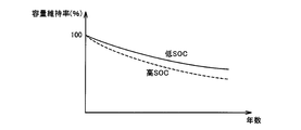
- FIG. 6 is a diagram for explaining the correlation between the years of use of the lithium ion battery and the capacity retention rate of the lithium ion battery.
- the capacity maintenance rate when the lithium ion battery is new is defined as 100%.
- the lithium ion battery gradually deteriorates as the hybrid vehicle 5 travels repeatedly using the electric power stored in the lithium ion battery.
- the capacity maintenance rate decreases as the service life of the lithium ion battery increases. That is, the full charge capacity of the lithium ion battery is reduced.
- the degree of decrease in the capacity maintenance rate with respect to the years of use increases as the SOC at the completion of charging of the lithium ion battery increases.
- the full charge capacity of the power storage device 10 may be reduced.
- the electric vehicle according to the present embodiment has a long life mode for extending the usage period of power storage device 10.
- the SOC control of power storage device 10 is switched between the normal mode and the long life mode as follows.
- control range is set so as to have a control width on the upper limit side and the lower limit side with respect to control center value SOCr.
- SOCl control lower limit value
- SOCu control upper limit value
- a reference upper limit value Smax and a reference lower limit value Smin are further set.
- the reference upper limit value Smax and the reference lower limit value Smin respectively correspond to a full charge state and an empty state in SOC control provided to avoid further overcharge or overdischarge.
- the SOC control range is set within the range of the reference lower limit value Smin to the reference upper limit value Smax. That is, control lower limit SOCl and control upper limit SOCu are set to have a margin with respect to reference lower limit Smin and reference upper limit Smax.
- the reference upper limit value Smax is a determination value for determining whether or not the SOC of the power storage device 10 has reached the fully charged state as described above. In the electrically powered vehicle according to the present embodiment, this reference upper limit value Smax is switched between the normal mode and the long life mode.
- first range R1 is an SOC reference range in the normal mode.
- the second range R2 is an SOC reference range in the long life mode.
- Smax1 indicates the upper limit value of the first range R1, that is, the reference upper limit value Smax in the normal mode.
- Smax2 indicates the upper limit value of the second range R2, that is, the reference upper limit value Smax in the long life mode.
- the lower limit value of the first range R1, that is, the reference lower limit value in the normal mode, and the lower limit value of the second range R2, that is, the reference lower limit value in the long life mode are both Smin.
- the lower limit value of the second range R2 may be larger than the lower limit value of the first range R1.
- Reference upper limit values Smax1 and Smax2 are both set to values smaller than 100% in order to prevent overcharging of power storage device 10.
- Reference lower limit Smin is set to a value greater than 0% in order to prevent overdischarge of power storage device 10.
- the reference upper limit value Smax2 in the long life mode is set to a value smaller than the reference upper limit value Smax1 in the normal mode.
- the power storage device 10 when the power storage device 10 is charged in the long life mode, it is possible to suppress a decrease in the full charge capacity of the power storage device 10. As a result, the cruising distance of the hybrid vehicle 5 can be ensured even when the power storage device 10 has been used for a long time.
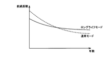
- FIG. 8 is a diagram for explaining the cruising distance in the long life mode and the cruising distance in the normal mode.
- power storage device 10 when power storage device 10 has a short service life, power storage device 10 can store a large amount of power because the degree of deterioration of power storage device 10 is small. Therefore, when the service life of power storage device 10 is short, the cruising distance in the normal mode is longer than the cruising distance in the long life mode.
- the hybrid vehicle 5 can travel a cruising distance longer than the cruising distance in the normal mode.
- the deterioration of the power storage device 10 proceeds as the service life of the power storage device 10 increases. Therefore, the cruising distance of hybrid vehicle 5 becomes shorter as the years of use of power storage device 10 become longer.
- reference upper limit value Smax2 is variably set according to the degree of deterioration of power storage device 10. Specifically, the reference upper limit value Smax2 is increased as the degree of decrease in the full charge capacity of the power storage device 10 increases so that the power storage device 10 maintains a predetermined reference capacity.
- FIG. 9 shows a more detailed configuration of charge / discharge control unit 150 (FIG. 4).
- charge / discharge control unit 150 includes a reference range setting unit 160, a charge / discharge upper limit setting unit 170, a control range setting unit 180, and a charge instruction unit 190.
- reference range setting unit 160 determines the SOC reference range (reference upper limit value Smax and reference lower limit value of power storage device 10). Smin) is set.
- reference range setting unit 160 determines that signal SLF has been generated, that is, long life mode has been selected as the charging mode of power storage device 10.
- signal SLF is not received from switch 56, it is determined that signal SLF is not generated, that is, the normal mode is selected as the charging mode of power storage device 10.
- the reference range setting unit 160 sets the reference upper limit value to Smax2 (FIG. 7).
- the reference range setting unit 160 sets the reference upper limit value to Smax1 (FIG. 7).
- the reference range setting unit 160 variably sets the reference upper limit value Smax2 according to the measured value CNT of the years of use of the power storage device 10. Specifically, reference range setting unit 160 increases reference upper limit value Smax2 in accordance with an increase in the number of years of use of power storage device 10.
- FIG. 10 is a conceptual diagram illustrating the setting of the reference upper limit value Smax2 with respect to the years of use of the power storage device 10.
- reference upper limit value Smax2 in the long life mode is set to S0 which is a default value when power storage device 10 is equivalent to a new product.
- S0 indicates the ratio of the reference capacity to the full charge capacity when the power storage device 10 is new.
- the reference capacity is set to a value having a margin with respect to the full charge capacity.
- the remaining capacity C0 of the power storage device 10 required to achieve the target value of the cruising distance of the hybrid vehicle 5 is set to a default value.
- the SOC of power storage device 10 reaches reference upper limit value Smax2, so that it is determined that power storage device 10 has reached a fully charged state. That is, the reference capacity corresponds to a threshold value for determining whether or not the power storage device 10 has reached a fully charged state.
- the full charge capacity of the power storage device 10 decreases as the age of the power storage device 10 increases. Therefore, if reference upper limit value Smax2 is fixed to default value S0, if the power storage device 10 has been used for a long time, the remaining capacity of power storage device 10 will remain even if the power storage device 10 is charged until the SOC reaches the reference upper limit value Smax2. May not meet the standard capacity. As a result, the cruising distance of the hybrid vehicle 5 may not reach the target value.
- the reference range setting unit 160 increases the reference upper limit value Smax2 in accordance with the degree of deterioration of the power storage device 10 (the degree of decrease in the full charge capacity) so that the reference capacity is secured when charging is completed. Specifically, when reference range setting unit 160 determines that the number of years of use of power storage device 10 has reached a predetermined number of years y0 based on measurement value CNT from degradation diagnosis unit 120, reference upper limit value Smax2 Is increased from the default value S0 to S1. S1 corresponds to the ratio of the reference capacity C0 to the full charge capacity when the power storage device 10 has been used for y0 years.
- the reference upper limit value Smax2 is maintained at S1. During this time, the full charge capacity of the power storage device 10 decreases.
- the reference range setting unit 160 increases the reference upper limit value Smax2 from S1 to S2.
- S2 corresponds to the ratio of the reference capacity C0 to the full charge capacity when the usage period of the power storage device 10 reaches 2y0 years.
- standard upper limit value Smax2 may be one time.
- the number of times the reference upper limit value Smax2 is increased can be determined based on the standard years of use of the power storage device 10, the full charge capacity of the power storage device 10, the target cruising distance, and the like.
- the reference upper limit value Smax2 may be increased according to the travel distance of the hybrid vehicle 5.
- FIG. 11 is a conceptual diagram illustrating the setting of the reference upper limit value Smax2 with respect to the travel distance of the hybrid vehicle 5.
- the reference upper limit value Smax2 is increased from the default value S0 to S1.
- S1 corresponds to the ratio of the reference capacity C0 to the full charge capacity when the travel distance of the hybrid vehicle 5 reaches a certain distance x0.
- the reference upper limit value Smax2 is maintained at S1 during the travel distance from x0 to 2x0. During this time, the full charge capacity of the power storage device 10 decreases. When the travel distance reaches 2 ⁇ 0 years, the reference range setting unit 160 increases the reference upper limit value Smax2 from S1 to S2. S2 corresponds to the ratio of the reference capacity C0 to the full charge capacity when the travel distance of the hybrid vehicle 5 reaches 2x0.
- the reference upper limit value Smax2 may be increased once instead of increasing the reference upper limit value Smax2 every predetermined distance x0.
- the number of times the reference upper limit value Smax2 is increased can be determined based on the standard years of use of the power storage device 10, the full charge capacity of the power storage device 10, the target cruising distance, and the like.
- FIG. 12 is a conceptual diagram illustrating the cruising distance of an electric vehicle that can be achieved by the SOC control according to the present embodiment.
- the solid line in FIG. 12 indicates the cruising distance of the hybrid vehicle 5 when the reference upper limit value Smax2 is increased at a predetermined timing based on the degree of deterioration of the power storage device 10.
- the dotted line in FIG. 12 indicates the cruising distance of the hybrid vehicle 5 when the reference upper limit value Smax2 is fixed to the default value S0.
- reference upper limit value Smax2 when reference upper limit value Smax2 is fixed to default value S0, the cruising distance decreases as the years of use of power storage device 10 increase. This is because the full charge capacity decreases as the number of years of use of the power storage device 10 increases.
- the reference upper limit Smax2 when the reference upper limit Smax2 is increased at an appropriate timing based on the degree of deterioration of the power storage device 10, the remaining capacity of the power storage device 10 can be maintained at the reference capacity C0. Can be extended. As a result, the target value of the cruising distance can be achieved when the target years of use have elapsed.
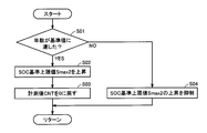
- FIG. 13 is a flowchart showing a control processing procedure for realizing the setting of the reference upper limit value Smax by the reference range setting unit 160 of FIG. Note that the flowchart shown in FIG. 13 is executed every predetermined time or every time a predetermined condition is satisfied when the long life mode is set to the charging mode.
- reference range setting unit 160 determines whether the age of power storage device 10 has reached the reference value (x0) based on measurement value CNT from deterioration diagnosis unit 120. judge. When it is determined that the age of power storage device 10 has not reached the reference value (NO in step S01), reference range setting unit 160 suppresses an increase in reference upper limit value Smax2 in step S04. That is, the reference upper limit value Smax2 does not change. When the process of step S04 ends, the entire process is returned to the main routine.
- reference range setting unit 160 increases reference upper limit value Smax2 in step S02. At this time, the reference range setting unit 160 increases the reference upper limit value Smax2 to a value that can secure the reference capacity C0.
- the reference range setting unit 160 returns the measured value CNT of the service life of the power storage device 10 to 0 in step S03.
- the process of step S03 ends, the entire process is returned to the main routine.
- charge / discharge upper limit setting unit 170 is configured to provide the maximum power value (charge power) that is allowed to be charged / discharged by power storage device 10 based at least on battery temperature Tb and estimated SOC value (#SOC).
- An upper limit value Win and a discharge power upper limit value Wout) are set.
- SOC estimated value (#SOC) decreases, discharge power upper limit value Wout is set gradually lower.
- SOC estimated value (#SOC) increases, charging power upper limit value Win is set to gradually decrease.
- Control range setting unit 180 sets the SOC control range of power storage device 10. As described above, the SOC control range is set to have control widths on the upper limit side and the lower limit side with respect to the control center value SOCr.
- Charging instruction unit 190 instructs charging of power storage device 10 when SOC estimated value (#SOC) falls below the SOC control range by control range setting unit 180, that is, when at least #SOC ⁇ SOCl. That is, Pch> 0 is set. Alternatively, Pch> 0 may be preliminarily set at the stage of SOCl ⁇ #SOC ⁇ SOCr. When Pch> 0, the operation of the engine 18 is required. When the engine 18 is stopped, the engine 18 is started. Then, the charging power command value Pch is added to the engine output request.
- SOCr ⁇ #SOC ⁇ SOCu the discharge of power storage device 10 is specified by setting Pch to the discharge side.
- the charge / discharge upper limit value setting unit 170 sets the charging power upper limit value Win low. Thereby, the overcharge of the electrical storage apparatus 10 is avoided.
- the regenerative power generated by the motor generator MG2 during deceleration or traveling downhill exceeds the charging power upper limit Win
- regenerative power generation by the motor generator MG2 is restricted or prohibited. Therefore, there is a possibility that a necessary braking force cannot be generated in the entire hybrid vehicle 5.
- the regenerative braking force by motor generator MG2 and the hydraulic braking force by a hydraulic brake mechanism may be coordinated to generate the required braking force for the entire vehicle. it can.
- the required braking force for the entire vehicle can be generated only by the hydraulic brake mechanism.
- the reference upper limit value Smax2 in the long life mode is lower than the reference upper limit value Smax1 in the normal mode. Therefore, when the long life mode is selected as the charging mode, the charging power upper limit value Win is set lower than when the normal mode is selected, so the degree of restriction on regenerative power generation is high. Become. As a result, there is a risk that the deterioration of the feeling during braking becomes more remarkable.
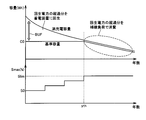
- FIG. 14 shows changes in the full charge capacity and the reference capacity of power storage device 10 in the electric vehicle according to the present embodiment.
- the full charge capacity of power storage device 10 decreases as the age of power storage device 10 increases.
- the reference capacity is set to have a margin with respect to the full charge capacity.
- the remaining capacity C0 required to achieve the target value of the cruising distance of the hybrid vehicle 5 is set to the default value as the reference capacity.
- the reference upper limit value Smax of the SOC of the power storage device 10 corresponds to the ratio of the reference capacity to the full charge capacity of the power storage device 10.
- the reference range setting unit 160 sets the power storage device 10 so that the power storage device 10 maintains the reference capacity C0 (default value) as described above.
- the reference upper limit value Smax2 is increased according to the degree of decrease in the full charge capacity.
- the reference range setting unit 160 The reference capacity is changed from the default value C0 to the full charge capacity. That is, after the usage years reach the predetermined number of years yth, the reference capacity gradually decreases from the default value C0 as the usage years increase.
- the reference upper limit value Smax2 becomes higher than the default value S0 as the service life becomes longer, with S0 as a default value until the service life of the power storage device 10 reaches the predetermined year yth.
- the reference upper limit value Smax2 is fixed to a predetermined value Slim corresponding to the ratio of the reference capacity to the full charge capacity.
- the reference capacity is a threshold value for determining whether or not the power storage device 10 has reached the full charge state, and the default value C0 is set so as to have a margin with respect to the full charge capacity.
- BUF in the figure indicates a margin.
- the margin BUF decreases as the full charge capacity decreases until the number of years of use reaches the predetermined number of years yth, and becomes substantially zero after the number of years of use reaches the predetermined number of years yth. That is, the margin BUF decreases as the degree of deterioration of the power storage device 10 increases.
- traveling control unit 200 (FIG. 4) determines an excess from charge power upper limit Win according to the degree of decrease in margin BUF. The control for regenerating the power storage device 10 and the control for consuming the excess using an auxiliary machine load are switched.
- traveling control unit 200 causes margin BUF provided in the remaining capacity to function as a power buffer for storing regenerative power generated by motor generator MG2. Therefore, the excess of the regenerative power with respect to the charging power upper limit value Win is collected in this power buffer. That is, the regenerative power generated by motor generator MG2 is regenerated in power storage device 10. As a result, the stored power of power storage device 10 can be increased, so that the energy efficiency of hybrid vehicle 5 can be improved.
- traveling control unit 200 collects the recovery destination of the excess regenerative power of motor generator MG2 with respect to charging power upper limit Win from the power buffer in power storage device 10 as an auxiliary load (complementary load).
- auxiliary load complementary load
- Machine 42 and air conditioner 44 That is, the excess of the regenerative power of motor generator MG2 is consumed using the auxiliary load.
- traveling control unit 200 determines the charge power according to the correlation between the full charge capacity of power storage device 10 and the reference capacity.
- the power buffer margin BUF in FIG. 14
- the auxiliary load in the power storage device 10 is selected.
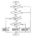
- FIG. 15 is a flowchart showing a control processing procedure for realizing charge control of the power storage device during regenerative braking in the electric vehicle according to the present embodiment.
- traveling control unit 200 determines whether hybrid vehicle 5 is traveling based on traveling mode flag FM sent from traveling mode selecting unit 210 in step S11. When hybrid vehicle 5 is not traveling (NO in step S11), the process related to the charging control of power storage device 10 ends.
- traveling control unit 200 regenerates motor generator MG2 based on the output request of motor generator MG2 in step S12. It is determined whether or not. Specifically, traveling control unit 200 determines that motor generator MG2 is regenerating when the torque command value of motor generator MG2 differs from the sign of the motor speed. When motor generator MG2 is not regenerating (NO in step S12), the process ends.
- traveling control unit 200 determines in step S13 that the regenerative power generated by motor generator MG2 is equal to charging power upper limit value Win of power storage device 10. It is determined whether or not it exceeds.
- the charging power upper limit value Win in step S13 is calculated by the charge / discharge upper limit setting unit 170 based on the reference upper limit value Smax set by the processing flow shown in FIG.
- traveling control unit 200 collects this regenerative power as charging power for power storage device 10 in step S15. .
- step S14 reference upper limit Smax of power storage device 10 is determined. Is compared with a predetermined value Slim.
- the process of step S14 corresponds to comparing the full charge capacity of the power storage device 10 with the reference capacity C0.
- the travel control unit 200 By S16, the excess of the regenerative power with respect to the charging power upper limit value Win is collected by the power buffer BUF in the power storage device 10.
- the full charge state in the SOC control is set so as to have a margin with respect to the full charge capacity of the power storage device, and the deterioration (full charge) of the power storage device is set.
- Control that regenerates the excess of regenerative power from the charge power upper limit value defined in association with the full charge state to the power storage device "Corresponding to” first control ") and control (corresponding to” second control "in the present invention) for consuming the excess using the auxiliary load.
- the electric vehicle to which the charging control of the in-vehicle power storage device according to the present embodiment is applied is not limited to the hybrid vehicle 5 illustrated in FIG.
- the present invention is not limited to a hybrid vehicle, as long as it has a configuration that regenerates electric power generated by regenerative braking by an electric motor in a power storage device, regardless of the number of mounted electric motors (motor generators) and the configuration of a drive system. It can be commonly applied to all electric vehicles including electric vehicles and fuel cell vehicles not equipped with an engine.
- the configuration of the hybrid vehicle is not limited to the example shown in FIG. 1, and the fact that the present invention can be applied to any configuration including a parallel hybrid vehicle is confirmed. To do.
- the present invention can be applied to an electric vehicle equipped with a power storage device and an electric motor that generates a regenerative braking force.
Landscapes
- Engineering & Computer Science (AREA)
- Power Engineering (AREA)
- Transportation (AREA)
- Mechanical Engineering (AREA)
- Life Sciences & Earth Sciences (AREA)
- Sustainable Development (AREA)
- Sustainable Energy (AREA)
- Electric Propulsion And Braking For Vehicles (AREA)
- Charge And Discharge Circuits For Batteries Or The Like (AREA)
Priority Applications (5)
| Application Number | Priority Date | Filing Date | Title |
|---|---|---|---|
| JP2013519260A JP5772952B2 (ja) | 2011-06-07 | 2011-06-07 | 電動車両および電動車両の制御方法 |
| EP11867326.8A EP2719572B1 (de) | 2011-06-07 | 2011-06-07 | Elektrofahrzeug und steuerungsverfahren für ein elektrofahrzeug |
| CN201180071492.8A CN103596798B (zh) | 2011-06-07 | 2011-06-07 | 电动车辆和电动车辆的控制方法 |
| US14/124,401 US9233613B2 (en) | 2011-06-07 | 2011-06-07 | Electrically powered vehicle and method for controlling electrically powered vehicle |
| PCT/JP2011/063029 WO2012169009A1 (ja) | 2011-06-07 | 2011-06-07 | 電動車両および電動車両の制御方法 |
Applications Claiming Priority (1)
| Application Number | Priority Date | Filing Date | Title |
|---|---|---|---|
| PCT/JP2011/063029 WO2012169009A1 (ja) | 2011-06-07 | 2011-06-07 | 電動車両および電動車両の制御方法 |
Publications (1)
| Publication Number | Publication Date |
|---|---|
| WO2012169009A1 true WO2012169009A1 (ja) | 2012-12-13 |
Family
ID=47295616
Family Applications (1)
| Application Number | Title | Priority Date | Filing Date |
|---|---|---|---|
| PCT/JP2011/063029 WO2012169009A1 (ja) | 2011-06-07 | 2011-06-07 | 電動車両および電動車両の制御方法 |
Country Status (5)
| Country | Link |
|---|---|
| US (1) | US9233613B2 (de) |
| EP (1) | EP2719572B1 (de) |
| JP (1) | JP5772952B2 (de) |
| CN (1) | CN103596798B (de) |
| WO (1) | WO2012169009A1 (de) |
Cited By (12)
| Publication number | Priority date | Publication date | Assignee | Title |
|---|---|---|---|---|
| JP2014155292A (ja) * | 2013-02-07 | 2014-08-25 | Nabtesco Corp | 電力回生システム及びこれを備える車両 |
| JP2014187853A (ja) * | 2013-03-25 | 2014-10-02 | Toyota Motor Corp | 車両 |
| WO2014109887A3 (en) * | 2013-01-11 | 2015-04-02 | Johnson Controls Technology Company | Vehicle accessory load controller and method |
| JP2015080284A (ja) * | 2013-10-15 | 2015-04-23 | 株式会社デンソー | 電池暖機システム |
| WO2015097996A1 (en) * | 2013-12-26 | 2015-07-02 | Toyota Jidosha Kabushiki Kaisha | Power supply control device and power supply control method |
| JP2016056527A (ja) * | 2014-09-05 | 2016-04-21 | 日立建機株式会社 | ハイブリッド式建設機械 |
| EP3114493A1 (de) * | 2014-03-07 | 2017-01-11 | Renault S.A.S. | Verfahren zur beurteilung eines zustands einer batterie mit einer vielzahl von zellen mit einem variablen verwendungsbereich an ladezuständen |
| JP2017186007A (ja) * | 2013-11-20 | 2017-10-12 | トヨタ自動車株式会社 | ハイブリッド車両の制御装置 |
| JPWO2017017816A1 (ja) * | 2015-07-29 | 2018-05-24 | 日産自動車株式会社 | 電動車両の制御装置、および、電動車両の制御方法 |
| JP2019087496A (ja) * | 2017-11-09 | 2019-06-06 | トヨタ自動車株式会社 | 電池システム |
| JP2019149863A (ja) * | 2018-02-26 | 2019-09-05 | ファナック株式会社 | 蓄電装置を有するモータ駆動システム |
| JP2020124072A (ja) * | 2019-01-31 | 2020-08-13 | トヨタ自動車株式会社 | 車両 |
Families Citing this family (32)
| Publication number | Priority date | Publication date | Assignee | Title |
|---|---|---|---|---|
| KR20140023434A (ko) * | 2011-06-17 | 2014-02-26 | 도요타 지도샤(주) | 전동 차량 및 전동 차량의 제어 방법 |
| EP2546089A3 (de) * | 2011-07-15 | 2017-08-23 | Mitsubishi Jidosha Kogyo Kabushiki Kaisha | Rekuperationssteuerungsvorrichtung vom elektrisch angetriebenen Fahrzeug |
| KR101509944B1 (ko) * | 2013-10-22 | 2015-04-07 | 현대자동차주식회사 | 에어컨 제어방법 |
| KR101558363B1 (ko) * | 2013-12-12 | 2015-10-07 | 현대자동차 주식회사 | 배터리의 충방전 제어 방법 및 시스템 |
| DE102014110456A1 (de) * | 2014-07-24 | 2016-01-28 | Linde Material Handling Gmbh | Verfahren zur Steuerung einer Lithiumionenbatterie eines Flurförderzeugs |
| CN104600982B (zh) * | 2015-01-06 | 2017-02-01 | 上海电力学院 | 一种多工作模式的新能源混合系统功率控制器设计方法 |
| JP6252519B2 (ja) * | 2015-03-06 | 2017-12-27 | トヨタ自動車株式会社 | ハイブリッド車の制御装置 |
| US11479139B2 (en) * | 2015-09-11 | 2022-10-25 | Invertedpower Pty Ltd | Methods and systems for an integrated charging system for an electric vehicle |
| KR20170060499A (ko) * | 2015-11-24 | 2017-06-01 | 현대자동차주식회사 | 배터리의 출력을 제어하는 방법 |
| US10176100B1 (en) * | 2015-12-21 | 2019-01-08 | Cadence Design Systems, Inc. | Cache coherency process |
| US11014549B1 (en) | 2016-01-04 | 2021-05-25 | Hydro-Gear Limited Partnership | Regeneration power control |
| US10183662B1 (en) * | 2016-01-04 | 2019-01-22 | Hydro-Gear Limited Partnership | Regeneration power control |
| JP6376160B2 (ja) * | 2016-03-22 | 2018-08-22 | トヨタ自動車株式会社 | 自動車 |
| US20180162432A1 (en) * | 2016-12-08 | 2018-06-14 | Wal-Mart Stores, Inc. | Self-charging shopping cart system with power assist |
| KR102371597B1 (ko) * | 2017-04-06 | 2022-03-07 | 현대자동차주식회사 | 차량의 급속충전 제어 장치 및 방법 |
| US10649512B2 (en) * | 2017-07-25 | 2020-05-12 | Quanta Computer Inc. | High efficient battery backup system |
| US10784701B2 (en) * | 2017-12-07 | 2020-09-22 | The Boeing Company | Power system architecture for aircraft with electrical actuation |
| JP6584019B2 (ja) * | 2017-12-21 | 2019-10-02 | 本田技研工業株式会社 | 電動車両 |
| JP6977622B2 (ja) * | 2018-03-06 | 2021-12-08 | トヨタ自動車株式会社 | ハイブリッド車両の制御装置 |
| JP7020293B2 (ja) * | 2018-05-25 | 2022-02-16 | トヨタ自動車株式会社 | バッテリ放電制御装置 |
| JP7047603B2 (ja) * | 2018-06-01 | 2022-04-05 | トヨタ自動車株式会社 | 車両 |
| JP2020058131A (ja) * | 2018-10-01 | 2020-04-09 | 株式会社Soken | 駆動システム |
| JP7151367B2 (ja) * | 2018-10-19 | 2022-10-12 | トヨタ自動車株式会社 | 車両およびその制御方法 |
| JP7010191B2 (ja) * | 2018-10-23 | 2022-02-10 | トヨタ自動車株式会社 | 二次電池システムおよび二次電池の充電制御方法 |
| JP7070332B2 (ja) * | 2018-10-29 | 2022-05-18 | トヨタ自動車株式会社 | 電動車両 |
| CN111993899A (zh) * | 2019-05-27 | 2020-11-27 | 观致汽车有限公司 | 一种新能源车辆的能量管理方法及能量管理系统 |
| WO2020240910A1 (ja) * | 2019-05-27 | 2020-12-03 | パナソニックIpマネジメント株式会社 | 情報処理方法、及び、情報処理システム |
| DE102019209854A1 (de) | 2019-07-04 | 2021-01-07 | Vitesco Technologies GmbH | Fahrzeugbordnetz |
| JP7156194B2 (ja) * | 2019-07-17 | 2022-10-19 | トヨタ自動車株式会社 | ハイブリッド車両 |
| JP2021138242A (ja) * | 2020-03-04 | 2021-09-16 | 本田技研工業株式会社 | ハイブリッド車両およびその廃電制御方法 |
| DE102021109317A1 (de) * | 2021-04-14 | 2022-10-20 | Man Truck & Bus Se | Verfahren und Vorrichtung zum Betrieb eines elektrischen Energiespeichers |
| JP2024033347A (ja) * | 2022-08-30 | 2024-03-13 | 株式会社クボタ | 電動作業車、及び、充電方法 |
Citations (5)
| Publication number | Priority date | Publication date | Assignee | Title |
|---|---|---|---|---|
| JPH05284607A (ja) * | 1992-03-27 | 1993-10-29 | Toyota Motor Corp | 電気自動車の制動制御装置 |
| JP2003199211A (ja) * | 2001-12-25 | 2003-07-11 | Toyota Motor Corp | 自動車用のバッテリ充放電制御装置 |
| JP2005130629A (ja) * | 2003-10-24 | 2005-05-19 | Toyota Motor Corp | 自動車 |
| JP2005137091A (ja) * | 2003-10-29 | 2005-05-26 | Toyota Motor Corp | 二次電池の制御装置および制御方法 |
| JP2010119180A (ja) * | 2008-11-12 | 2010-05-27 | Toyota Motor Corp | 車両の制御装置 |
Family Cites Families (27)
| Publication number | Priority date | Publication date | Assignee | Title |
|---|---|---|---|---|
| WO1994021481A1 (en) | 1993-03-22 | 1994-09-29 | Seiko Epson Corporation | Electric vehicle |
| JP3736268B2 (ja) * | 2000-03-21 | 2006-01-18 | 日産自動車株式会社 | ハイブリッド車両の制御装置 |
| JP3904388B2 (ja) * | 2000-12-04 | 2007-04-11 | 松下電器産業株式会社 | ハイブリッド自動車の制御装置 |
| JP2003125501A (ja) | 2001-10-10 | 2003-04-25 | Nissan Motor Co Ltd | ハイブリッド車両の回生制動装置 |
| JP2003134602A (ja) | 2001-10-22 | 2003-05-09 | Nissan Motor Co Ltd | ハイブリッド車両の回生エネルギー制御装置 |
| JP4052080B2 (ja) * | 2002-10-09 | 2008-02-27 | アイシン・エィ・ダブリュ株式会社 | 車輌の制御装置 |
| JP2005065352A (ja) | 2003-08-11 | 2005-03-10 | Nissan Motor Co Ltd | バッテリ充放電制御装置 |
| JP2006174543A (ja) | 2004-12-13 | 2006-06-29 | Honda Motor Co Ltd | ハイブリッド車両における回生電力制御装置 |
| US8026698B2 (en) * | 2006-02-09 | 2011-09-27 | Scheucher Karl F | Scalable intelligent power supply system and method |
| JP4644163B2 (ja) * | 2006-07-04 | 2011-03-02 | トヨタ自動車株式会社 | 車両の電力制御装置 |
| KR20080044097A (ko) * | 2006-11-15 | 2008-05-20 | 현대자동차주식회사 | 수퍼커패시터를 이용한 연료전지 차량의 회생제동 시스템 |
| JP2008189121A (ja) | 2007-02-05 | 2008-08-21 | Toyota Motor Corp | ハイブリッド車両 |
| JP2008308122A (ja) | 2007-06-18 | 2008-12-25 | Mazda Motor Corp | 車両用バッテリの制御装置 |
| JP4372818B2 (ja) * | 2007-10-19 | 2009-11-25 | トヨタ自動車株式会社 | 外部充電ev/hv自動車 |
| DE102007047821A1 (de) * | 2007-11-20 | 2009-05-28 | Zf Friedrichshafen Ag | Verfahren zur Optimierung der Energierückgewinnung bei einem Hybridfahrzeug |
| JP2009196404A (ja) * | 2008-02-19 | 2009-09-03 | Fujitsu Ten Ltd | ハイブリッド制御装置、空調制御装置、ハイブリッド車両の制御方法 |
| JP2009274549A (ja) | 2008-05-14 | 2009-11-26 | Toyota Motor Corp | 車両の電源装置 |
| CN102089956B (zh) * | 2008-07-11 | 2013-06-05 | 丰田自动车株式会社 | 电池的充放电控制装置以及具备该装置的混合动力汽车 |
| JP4930482B2 (ja) * | 2008-09-30 | 2012-05-16 | 株式会社デンソー | バッテリの充放電制御装置 |
| JP5083152B2 (ja) | 2008-09-30 | 2012-11-28 | トヨタ自動車株式会社 | 車両および二次電池の充電方法 |
| CN102341285B (zh) * | 2009-03-05 | 2014-07-30 | 丰田自动车株式会社 | 混合动力车辆的充放电控制系统及其控制方法 |
| JP5158217B2 (ja) * | 2009-06-18 | 2013-03-06 | トヨタ自動車株式会社 | 電池システム及び電池システム搭載車両 |
| EP2272722B1 (de) * | 2009-07-01 | 2015-04-08 | Denso Corporation | Stromquellenvorrichtung für ein Fahrzeug |
| CN102648106B (zh) * | 2009-11-17 | 2014-04-02 | 丰田自动车株式会社 | 车辆及车辆的控制方法 |
| JP5370492B2 (ja) | 2009-11-17 | 2013-12-18 | トヨタ自動車株式会社 | 車両および車両の制御方法 |
| US8820446B2 (en) * | 2009-11-17 | 2014-09-02 | Toyota Jidosha Kabushiki Kaisha | Vehicle and method for controlling vehicle |
| US8630759B2 (en) * | 2009-11-20 | 2014-01-14 | GM Global Technology Operations LLC | Control of regenerative braking in a hybrid vehicle |
-
2011
- 2011-06-07 WO PCT/JP2011/063029 patent/WO2012169009A1/ja active Application Filing
- 2011-06-07 EP EP11867326.8A patent/EP2719572B1/de active Active
- 2011-06-07 US US14/124,401 patent/US9233613B2/en active Active
- 2011-06-07 JP JP2013519260A patent/JP5772952B2/ja active Active
- 2011-06-07 CN CN201180071492.8A patent/CN103596798B/zh active Active
Patent Citations (5)
| Publication number | Priority date | Publication date | Assignee | Title |
|---|---|---|---|---|
| JPH05284607A (ja) * | 1992-03-27 | 1993-10-29 | Toyota Motor Corp | 電気自動車の制動制御装置 |
| JP2003199211A (ja) * | 2001-12-25 | 2003-07-11 | Toyota Motor Corp | 自動車用のバッテリ充放電制御装置 |
| JP2005130629A (ja) * | 2003-10-24 | 2005-05-19 | Toyota Motor Corp | 自動車 |
| JP2005137091A (ja) * | 2003-10-29 | 2005-05-26 | Toyota Motor Corp | 二次電池の制御装置および制御方法 |
| JP2010119180A (ja) * | 2008-11-12 | 2010-05-27 | Toyota Motor Corp | 車両の制御装置 |
Non-Patent Citations (1)
| Title |
|---|
| See also references of EP2719572A4 * |
Cited By (19)
| Publication number | Priority date | Publication date | Assignee | Title |
|---|---|---|---|---|
| WO2014109887A3 (en) * | 2013-01-11 | 2015-04-02 | Johnson Controls Technology Company | Vehicle accessory load controller and method |
| JP2014155292A (ja) * | 2013-02-07 | 2014-08-25 | Nabtesco Corp | 電力回生システム及びこれを備える車両 |
| JP2014187853A (ja) * | 2013-03-25 | 2014-10-02 | Toyota Motor Corp | 車両 |
| WO2014155434A1 (ja) * | 2013-03-25 | 2014-10-02 | トヨタ自動車株式会社 | 車両 |
| CN105052002A (zh) * | 2013-03-25 | 2015-11-11 | 丰田自动车株式会社 | 车辆 |
| JP2015080284A (ja) * | 2013-10-15 | 2015-04-23 | 株式会社デンソー | 電池暖機システム |
| JP2017186007A (ja) * | 2013-11-20 | 2017-10-12 | トヨタ自動車株式会社 | ハイブリッド車両の制御装置 |
| CN105849997A (zh) * | 2013-12-26 | 2016-08-10 | 丰田自动车株式会社 | 电源控制装置和电源控制方法 |
| WO2015097996A1 (en) * | 2013-12-26 | 2015-07-02 | Toyota Jidosha Kabushiki Kaisha | Power supply control device and power supply control method |
| CN105849997B (zh) * | 2013-12-26 | 2018-05-25 | 丰田自动车株式会社 | 电源控制装置和电源控制方法 |
| EP3114493A1 (de) * | 2014-03-07 | 2017-01-11 | Renault S.A.S. | Verfahren zur beurteilung eines zustands einer batterie mit einer vielzahl von zellen mit einem variablen verwendungsbereich an ladezuständen |
| EP3114493B1 (de) * | 2014-03-07 | 2023-05-03 | Renault s.a.s | Verfahren zur beurteilung eines zustands einer batterie mit einer vielzahl von zellen mit einem variablen verwendungsbereich an ladezuständen |
| JP2016056527A (ja) * | 2014-09-05 | 2016-04-21 | 日立建機株式会社 | ハイブリッド式建設機械 |
| JPWO2017017816A1 (ja) * | 2015-07-29 | 2018-05-24 | 日産自動車株式会社 | 電動車両の制御装置、および、電動車両の制御方法 |
| JP2019087496A (ja) * | 2017-11-09 | 2019-06-06 | トヨタ自動車株式会社 | 電池システム |
| JP2019149863A (ja) * | 2018-02-26 | 2019-09-05 | ファナック株式会社 | 蓄電装置を有するモータ駆動システム |
| US10965151B2 (en) | 2018-02-26 | 2021-03-30 | Fanuc Corporation | Motor drive system including power storage device |
| JP2020124072A (ja) * | 2019-01-31 | 2020-08-13 | トヨタ自動車株式会社 | 車両 |
| JP7131413B2 (ja) | 2019-01-31 | 2022-09-06 | トヨタ自動車株式会社 | 車両 |
Also Published As
| Publication number | Publication date |
|---|---|
| JP5772952B2 (ja) | 2015-09-02 |
| JPWO2012169009A1 (ja) | 2015-02-23 |
| CN103596798A (zh) | 2014-02-19 |
| US20140097676A1 (en) | 2014-04-10 |
| US9233613B2 (en) | 2016-01-12 |
| EP2719572B1 (de) | 2018-03-21 |
| EP2719572A1 (de) | 2014-04-16 |
| EP2719572A4 (de) | 2016-03-02 |
| CN103596798B (zh) | 2015-11-25 |
Similar Documents
| Publication | Publication Date | Title |
|---|---|---|
| JP5772952B2 (ja) | 電動車両および電動車両の制御方法 | |
| JP5730501B2 (ja) | 電動車両およびその制御方法 | |
| JP5418676B2 (ja) | 電動車両およびその制御方法 | |
| JP5626465B2 (ja) | 電動車両および電動車両の制御方法 | |
| JP5716693B2 (ja) | ハイブリッド車両 | |
| JP5913314B2 (ja) | ハイブリッド車両の制御装置および制御方法 | |
| US8571734B2 (en) | Power supply system for electrically powered vehicle and method for controlling the same | |
| JP5278614B2 (ja) | ハイブリッド車両およびその制御方法 | |
| JP4743082B2 (ja) | 電源システムおよびそれを備えた車両 | |
| JP5608747B2 (ja) | 蓄電容量管理装置 | |
| WO2012131864A1 (ja) | 電動車両およびその制御方法 | |
| WO2013018208A1 (ja) | ハイブリッド車両およびその制御方法 | |
| JP2011093335A (ja) | ハイブリッド車両の制御装置 | |
| JP6028328B2 (ja) | ハイブリッド車両 | |
| JP5729475B2 (ja) | 車両および車両の制御方法 | |
| JP5733198B2 (ja) | ハイブリッド車両 | |
| JP4706493B2 (ja) | 車両に搭載された二次電池の制御装置 | |
| JP2006136131A (ja) | 車両の制御装置 |
Legal Events
| Date | Code | Title | Description |
|---|---|---|---|
| 121 | Ep: the epo has been informed by wipo that ep was designated in this application |
Ref document number: 11867326 Country of ref document: EP Kind code of ref document: A1 |
|
| ENP | Entry into the national phase |
Ref document number: 2013519260 Country of ref document: JP Kind code of ref document: A |
|
| WWE | Wipo information: entry into national phase |
Ref document number: 14124401 Country of ref document: US |
|
| NENP | Non-entry into the national phase |
Ref country code: DE |